EP3893296A1 - Positive electrode for lithium ion secondary batteries, electrode paste for lithium ion secondary batteries, and lithium ion secondary battery - Google Patents
Positive electrode for lithium ion secondary batteries, electrode paste for lithium ion secondary batteries, and lithium ion secondary battery Download PDFInfo
- Publication number
- EP3893296A1 EP3893296A1 EP19892727.9A EP19892727A EP3893296A1 EP 3893296 A1 EP3893296 A1 EP 3893296A1 EP 19892727 A EP19892727 A EP 19892727A EP 3893296 A1 EP3893296 A1 EP 3893296A1
- Authority
- EP
- European Patent Office
- Prior art keywords
- lithium ion
- ion secondary
- lithium iron
- particle
- positive electrode
- Prior art date
- Legal status (The legal status is an assumption and is not a legal conclusion. Google has not performed a legal analysis and makes no representation as to the accuracy of the status listed.)
- Granted
Links
Images

Classifications
-
- H—ELECTRICITY
- H01—ELECTRIC ELEMENTS
- H01M—PROCESSES OR MEANS, e.g. BATTERIES, FOR THE DIRECT CONVERSION OF CHEMICAL ENERGY INTO ELECTRICAL ENERGY
- H01M4/00—Electrodes
- H01M4/02—Electrodes composed of, or comprising, active material
- H01M4/13—Electrodes for accumulators with non-aqueous electrolyte, e.g. for lithium-accumulators; Processes of manufacture thereof
- H01M4/131—Electrodes based on mixed oxides or hydroxides, or on mixtures of oxides or hydroxides, e.g. LiCoOx
-
- H—ELECTRICITY
- H01—ELECTRIC ELEMENTS
- H01M—PROCESSES OR MEANS, e.g. BATTERIES, FOR THE DIRECT CONVERSION OF CHEMICAL ENERGY INTO ELECTRICAL ENERGY
- H01M4/00—Electrodes
- H01M4/02—Electrodes composed of, or comprising, active material
- H01M4/36—Selection of substances as active materials, active masses, active liquids
- H01M4/362—Composites
- H01M4/364—Composites as mixtures
-
- H—ELECTRICITY
- H01—ELECTRIC ELEMENTS
- H01M—PROCESSES OR MEANS, e.g. BATTERIES, FOR THE DIRECT CONVERSION OF CHEMICAL ENERGY INTO ELECTRICAL ENERGY
- H01M10/00—Secondary cells; Manufacture thereof
- H01M10/05—Accumulators with non-aqueous electrolyte
- H01M10/052—Li-accumulators
-
- H—ELECTRICITY
- H01—ELECTRIC ELEMENTS
- H01M—PROCESSES OR MEANS, e.g. BATTERIES, FOR THE DIRECT CONVERSION OF CHEMICAL ENERGY INTO ELECTRICAL ENERGY
- H01M10/00—Secondary cells; Manufacture thereof
- H01M10/05—Accumulators with non-aqueous electrolyte
- H01M10/052—Li-accumulators
- H01M10/0525—Rocking-chair batteries, i.e. batteries with lithium insertion or intercalation in both electrodes; Lithium-ion batteries
-
- H—ELECTRICITY
- H01—ELECTRIC ELEMENTS
- H01M—PROCESSES OR MEANS, e.g. BATTERIES, FOR THE DIRECT CONVERSION OF CHEMICAL ENERGY INTO ELECTRICAL ENERGY
- H01M4/00—Electrodes
- H01M4/02—Electrodes composed of, or comprising, active material
- H01M4/13—Electrodes for accumulators with non-aqueous electrolyte, e.g. for lithium-accumulators; Processes of manufacture thereof
- H01M4/136—Electrodes based on inorganic compounds other than oxides or hydroxides, e.g. sulfides, selenides, tellurides, halogenides or LiCoFy
-
- H—ELECTRICITY
- H01—ELECTRIC ELEMENTS
- H01M—PROCESSES OR MEANS, e.g. BATTERIES, FOR THE DIRECT CONVERSION OF CHEMICAL ENERGY INTO ELECTRICAL ENERGY
- H01M4/00—Electrodes
- H01M4/02—Electrodes composed of, or comprising, active material
- H01M4/13—Electrodes for accumulators with non-aqueous electrolyte, e.g. for lithium-accumulators; Processes of manufacture thereof
- H01M4/139—Processes of manufacture
- H01M4/1391—Processes of manufacture of electrodes based on mixed oxides or hydroxides, or on mixtures of oxides or hydroxides, e.g. LiCoOx
-
- H—ELECTRICITY
- H01—ELECTRIC ELEMENTS
- H01M—PROCESSES OR MEANS, e.g. BATTERIES, FOR THE DIRECT CONVERSION OF CHEMICAL ENERGY INTO ELECTRICAL ENERGY
- H01M4/00—Electrodes
- H01M4/02—Electrodes composed of, or comprising, active material
- H01M4/13—Electrodes for accumulators with non-aqueous electrolyte, e.g. for lithium-accumulators; Processes of manufacture thereof
- H01M4/139—Processes of manufacture
- H01M4/1397—Processes of manufacture of electrodes based on inorganic compounds other than oxides or hydroxides, e.g. sulfides, selenides, tellurides, halogenides or LiCoFy
-
- H—ELECTRICITY
- H01—ELECTRIC ELEMENTS
- H01M—PROCESSES OR MEANS, e.g. BATTERIES, FOR THE DIRECT CONVERSION OF CHEMICAL ENERGY INTO ELECTRICAL ENERGY
- H01M4/00—Electrodes
- H01M4/02—Electrodes composed of, or comprising, active material
- H01M4/36—Selection of substances as active materials, active masses, active liquids
- H01M4/48—Selection of substances as active materials, active masses, active liquids of inorganic oxides or hydroxides
- H01M4/483—Selection of substances as active materials, active masses, active liquids of inorganic oxides or hydroxides for non-aqueous cells
-
- H—ELECTRICITY
- H01—ELECTRIC ELEMENTS
- H01M—PROCESSES OR MEANS, e.g. BATTERIES, FOR THE DIRECT CONVERSION OF CHEMICAL ENERGY INTO ELECTRICAL ENERGY
- H01M4/00—Electrodes
- H01M4/02—Electrodes composed of, or comprising, active material
- H01M4/36—Selection of substances as active materials, active masses, active liquids
- H01M4/48—Selection of substances as active materials, active masses, active liquids of inorganic oxides or hydroxides
- H01M4/50—Selection of substances as active materials, active masses, active liquids of inorganic oxides or hydroxides of manganese
- H01M4/505—Selection of substances as active materials, active masses, active liquids of inorganic oxides or hydroxides of manganese of mixed oxides or hydroxides containing manganese for inserting or intercalating light metals, e.g. LiMn2O4 or LiMn2OxFy
-
- H—ELECTRICITY
- H01—ELECTRIC ELEMENTS
- H01M—PROCESSES OR MEANS, e.g. BATTERIES, FOR THE DIRECT CONVERSION OF CHEMICAL ENERGY INTO ELECTRICAL ENERGY
- H01M4/00—Electrodes
- H01M4/02—Electrodes composed of, or comprising, active material
- H01M4/36—Selection of substances as active materials, active masses, active liquids
- H01M4/48—Selection of substances as active materials, active masses, active liquids of inorganic oxides or hydroxides
- H01M4/52—Selection of substances as active materials, active masses, active liquids of inorganic oxides or hydroxides of nickel, cobalt or iron
- H01M4/525—Selection of substances as active materials, active masses, active liquids of inorganic oxides or hydroxides of nickel, cobalt or iron of mixed oxides or hydroxides containing iron, cobalt or nickel for inserting or intercalating light metals, e.g. LiNiO2, LiCoO2 or LiCoOxFy
-
- H—ELECTRICITY
- H01—ELECTRIC ELEMENTS
- H01M—PROCESSES OR MEANS, e.g. BATTERIES, FOR THE DIRECT CONVERSION OF CHEMICAL ENERGY INTO ELECTRICAL ENERGY
- H01M4/00—Electrodes
- H01M4/02—Electrodes composed of, or comprising, active material
- H01M4/36—Selection of substances as active materials, active masses, active liquids
- H01M4/58—Selection of substances as active materials, active masses, active liquids of inorganic compounds other than oxides or hydroxides, e.g. sulfides, selenides, tellurides, halogenides or LiCoFy; of polyanionic structures, e.g. phosphates, silicates or borates
- H01M4/5825—Oxygenated metallic salts or polyanionic structures, e.g. borates, phosphates, silicates, olivines
-
- H—ELECTRICITY
- H01—ELECTRIC ELEMENTS
- H01M—PROCESSES OR MEANS, e.g. BATTERIES, FOR THE DIRECT CONVERSION OF CHEMICAL ENERGY INTO ELECTRICAL ENERGY
- H01M4/00—Electrodes
- H01M4/02—Electrodes composed of, or comprising, active material
- H01M2004/026—Electrodes composed of, or comprising, active material characterised by the polarity
- H01M2004/028—Positive electrodes
-
- Y—GENERAL TAGGING OF NEW TECHNOLOGICAL DEVELOPMENTS; GENERAL TAGGING OF CROSS-SECTIONAL TECHNOLOGIES SPANNING OVER SEVERAL SECTIONS OF THE IPC; TECHNICAL SUBJECTS COVERED BY FORMER USPC CROSS-REFERENCE ART COLLECTIONS [XRACs] AND DIGESTS
- Y02—TECHNOLOGIES OR APPLICATIONS FOR MITIGATION OR ADAPTATION AGAINST CLIMATE CHANGE
- Y02E—REDUCTION OF GREENHOUSE GAS [GHG] EMISSIONS, RELATED TO ENERGY GENERATION, TRANSMISSION OR DISTRIBUTION
- Y02E60/00—Enabling technologies; Technologies with a potential or indirect contribution to GHG emissions mitigation
- Y02E60/10—Energy storage using batteries
Definitions
- the present invention relates to a positive electrode for lithium ion secondary batteries, an electrode paste for lithium ion secondary batteries, and a lithium ion secondary battery.
- Lithium ion secondary batteries have a high energy density. Meanwhile, there is a possibility that a malfunction of a lithium ion secondary battery may cause the stored energy to be released in a short time, resulting in firing and burning of the battery. Therefore, for lithium ion secondary batteries, improvement of both the energy density and the safety is an important problem.
- a lithium ion secondary battery largely depends on its positive electrode active material.
- positive electrode active materials of lithium ion secondary batteries positive electrode active materials called layered oxide-based active materials, which are often used in smartphones and electric vehicles, particularly have a high energy density.
- a layered oxide-based positive electrode active material has a problem of the safety, such as a risk of firing caused by the release of oxygen in the battery due to overcharging.
- olivine-based positive electrode active materials such as lithium iron phosphate, which are often used in stationary batteries, do not easily release oxygen because the oxygen is covalently bonded to phosphorus, and are thus relatively stable even at a high temperature.
- olivine-based positive electrode active materials have an advantage of excellent safety, but also have a problem that the constant discharge voltage makes it difficult to estimate the remaining capacity of the battery from the discharge voltage.
- Patent Document 1 describes an attempt to improve the coulombic efficiency by mixing a layered oxide-based positive electrode active material and lithium iron manganese phosphate.
- Patent Document 1 describes no idea of controlling the discharge characteristic by the mixing ratio of the active material, and there is a problem that the remaining capacity management of a battery is difficult in the case of increasing the ratio of lithium iron manganese phosphate for improvement in the safety.
- Patent Document 2 discloses improvement in the low temperature characteristic by mixing three active materials and adding an additive. However, in the disclosed example, only lithium iron phosphate is mixed at a maximum of 20%, and the safety still remains a problem.
- An object of the present invention is to provide an electrode for lithium ion secondary batteries that allows production of a lithium ion battery having both high safety and improved accuracy of the remaining capacity management.
- the present invention is a lithium ion secondary battery including the positive electrode for lithium ion secondary batteries according to the present invention.
- the present invention is a lithium ion secondary battery characterized in that a discharge curve indicating a relationship between a discharge voltage and a discharge capacity of the lithium ion secondary battery has one non-plateau region between two plateau regions, and a width of the non-plateau region is 20% or more in terms of a state of charge (SOC).
- SOC state of charge
- a lithium ion secondary battery can be obtained that has high safety and allows estimation of the remaining capacity of the battery.
- lithium iron phosphate in the present description refers to a compound represented by LiFePO 4 .
- lithium iron phosphate also refers to a compound to which a metal other than Fe is added at a content in the range of 0.5 wt% or more and 5 wt% or less as doping.
- lithium iron manganese phosphate also refers to a compound to which a metal other than Mn and Fe is added at a content in the range of 0.5 wt% or more and 5 wt% or less as doping as long as the above-described general formula is satisfied in the compound.
- layered oxide-based positive electrode active material also refers to a compound to which a metal other than the above-described metals is added at a content in the range of 0.5 wt% or more and 5 wt% or less as doping as long as the above-described general formula is satisfied in the compound.
- each particle of the lithium iron phosphate, the lithium iron manganese phosphate, and the layered oxide-based active material may be a mixture of particles having different compositions as long as the above-described weight ratio is satisfied as a whole.
- the lithium iron manganese phosphate two or more kinds of active material particles can be used that are different in ⁇ and ⁇ in the composition formula LiMn ⁇ Fe ⁇ PO 4 . In such a case, the total weight of the active materials is regarded as the weight of the lithium iron manganese phosphate particle.
- SOC state of charge
- the discharge curve of a layered oxide-based active material generally has no plateau region, and the discharge voltage gradually decreases from the vicinity of 4.1 V to 2.5 V, so that estimation of the SOC from the discharge voltage is easy.
- the discharge curve of lithium iron phosphate has a long plateau region in the vicinity of a discharge voltage of 3.4 V.
- Lithium iron manganese phosphate has two plateau regions in the vicinity of 4 V correlating to the oxidation of manganese, and in the vicinity of 3.4 V correlating to the oxidation of iron. Therefore, even if lithium iron phosphate and lithium iron manganese phosphate are mixed, the discharge curve still has two plateau regions, so that estimation of the SOC from the discharge voltage is difficult.
- the term "plateau region" of the discharge voltage is defined as a portion where the amount of change in the voltage per 1 mAh/g of discharge is 4 mV or less. Since in a battery, the discharge voltage is determined by the combination of the positive electrode and the negative electrode, the term “discharge voltage” in the present description refers to the voltage in evaluation with a half cell using a lithium metal in the negative electrode.
- a lithium ion secondary battery in which the positive electrode according to the present invention including an olivine-based active material at a ratio of 50% or more is used (hereinafter sometimes simply referred to as "battery")
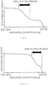
- the discharge curve has a non-plateau region located in the central part of the discharge curve as shown in Fig. 1 , not at the end of the discharge curve, that is, not in the vicinity of an SOC of 0% as shown in Fig. 2 . That is, a non-plateau region needs to be provided between the plateau in the vicinity of 4 V immediately after the start of discharge and the plateau in the vicinity of 3.4 V immediately before the completion of discharge. Correlating the voltage in the non-plateau region with the SOC improves the accuracy of the remaining capacity management of the battery.
- the plateau region located in the central part of the discharge curve allows highly accurate estimation of the SOC in the most frequently used capacity region.
- the ratio of the layered oxide-based active material particle is preferably a certain value or less. Therefore, when the weight ratio of the lithium iron phosphate particle, the lithium iron manganese phosphate particle, and the layered oxide-based active material particle is x : y : z, it is preferable that z be 0.40 or less, that is, x + y be 0.60 or more. From the viewpoint of improving the safety of the battery, z is preferably 0.30 or less.
- the discharge in the non-plateau region in the central part of the discharge curve largely correlates to the oxidation reaction of the layered oxide-based active material. Therefore, a high ratio of the layered oxide-based active material leads to expansion of the non-plateau region. If the non-plateau region is short, the range of the SOC that can be accurately measured is so small that the remaining capacity management of the battery is difficult.
- the width of the non-plateau region needs to occupy 20% or more in terms of the SOC, and z is preferably 0.10 or more to achieve the width.
- the width of the non-plateau region is preferably 30% or more in terms of the SOC.
- the phrase "in terms of the SOC" for indication of the width of the non-plateau region means that the width is determined by the SOC difference between both ends of the non-plateau region.
- the ratio of the lithium iron phosphate and the lithium iron manganese phosphate in the positive electrode is important for ensuring that the discharge curve has a non-plateau region located in the central part of the discharge curve, and in the present invention, it is preferable that 0.10 ⁇ x ⁇ 0.60 and 0.10 ⁇ y ⁇ 0.70.
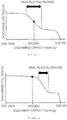
- the discharge curve has a non-plateau region located in the central part of the discharge curve, and the discharge voltage at an SOC of 50% is preferably included in the non-plateau region as shown in Fig. 3 so that the non-plateau region is the most frequently used capacity region, rather than not included in the non-plateau region as shown in Fig. 4 .
- the discharge voltage at an SOC of 50% is included in the non-plateau region
- the non-plateau region is closer to the high SOC side when x is large and closer to the low SOC side when y is large, it is particularly preferable that 0.20 ⁇ x ⁇ 0.45 and 0.30 ⁇ y ⁇ 0.60 in the mixing weight ratio.
- the lithium ion secondary battery according to the present invention is characterized in that the discharge curve indicating the relationship between the discharge voltage and the discharge capacity of the lithium ion secondary battery has one non-plateau region between two plateau regions. Also with a positive electrode in which an olivine-based active material and/or a layered oxide-based active material is not used, a battery that facilitates the SOC management can be obtained by using two kinds of positive electrode active materials having different plateau regions and one kind of positive electrode active material having no plateau region in combination.
- the discharge curve has a non-plateau region located in the central part of the discharge curve, that is, a non-plateau region is provided between the plateau immediately after the start of discharge and the plateau immediately before the completion of discharge, the discharge curve is understood to have one non-plateau region between two plateau regions.
- the discharge curve having a non-plateau region located at the end of the discharge curve, that is, in the vicinity of an SOC of 0% is not understood to have one non-plateau region between two plateau regions.
- the lithium iron phosphate particle used in the present invention preferably has an average primary particle size of 50 nm or more and 300 nm or less. If the average primary particle size is less than 50 nm, the specific surface area is so large that the cycle resistance is sometimes deteriorated. If the average primary particle size is more than 300 nm, the electron conductivity and the ion conductivity sometimes start to limit the rate of rapid charge/discharge.
- the lithium iron phosphate particle can be obtained by a known method such as a solid phase method or a liquid phase method, and commercially available lithium iron phosphate can also be used.
- the lithium iron manganese phosphate particle used in the present invention preferably has an average primary particle size of 30 nm or more and 100 nm or less. If the average primary particle size is less than 30 nm, the specific surface area is so large that the cycle resistance is sometimes deteriorated. If the average primary particle size is more than 100 nm, the electron conductivity and the ion conductivity sometimes start to limit the rate of rapid charge/discharge.
- the lithium iron manganese phosphate particle can be obtained by a known method such as a solid phase method or a liquid phase method, and a liquid phase method is preferable from the viewpoint of obtaining a particle having a particle size of 30 nm or more and 100 nm or less further easily.
- a liquid phase method is preferable from the viewpoint of obtaining a particle having a particle size of 30 nm or more and 100 nm or less further easily.
- the liquid phase water, and in addition, an organic solvent are preferably used for reducing the particle size to the size of a nanoparticle, and the solvent is preferably an alcohol-based solvent.
- the solvent specifically include ethylene glycol, diethylene glycol, triethylene glycol, tetraethylene glycol, 2-propanol, 1,3-propanediol, 1,4-butanediol, and dimethylsulfoxide.
- the synthesis process may include pressurizing for improvement of the crystallinity of the particle.
- the layered oxide-based active material particle can be obtained by a solid phase method in accordance with a known method, and a commercially available active material can also be used.
- the layered oxide-based particle preferably has an average primary particle size of 100 nm or more and 10 ⁇ m or less. If the average primary particle size is less than 100 nm, the specific surface area is so large that the cycle resistance is sometimes deteriorated. If the average primary particle size is more than 1 ⁇ m, the electron conductivity and the ion conductivity sometimes start to limit the rate of rapid charge/discharge.
- carbon coating is preferably applied to the surface of the primary particle when lithium iron phosphate and lithium iron manganese phosphate are used.
- a method is preferably used in which an active material particle and a saccharide are mixed and then the resulting mixture is fired at 600°C to 750°C.
- the saccharide glucose or sucrose is preferable from the viewpoint of the small ash content after firing.
- the lithium iron phosphate particle, the lithium iron manganese phosphate particle, and the layered oxide-based active material particle are preferably granulated to have an average secondary particle size of 1 ⁇ m or more and 20 ⁇ m or less. If the average secondary particle size is less than 1 ⁇ m, a large amount of solvent is needed to make the active material particle into an electrode paste. If the average secondary particle size is more than 20 ⁇ m, it is difficult to obtain a smooth electrode having a thickness of 50 to 100 ⁇ m, which is the standard thickness of an electrode for lithium ion secondary batteries.
- the granulation can employ various methods, and a spray dryer is preferably used in order to obtain a granulated body having a particle size distribution as narrow as possible.
- the layered oxide-based active material particle has more excellent electron conductivity and more excellent lithium ion conductivity than lithium iron phosphate, and therefore, is also used without granulation in a preferable aspect.
- the average primary particle size and the average secondary particle size of the active material particle in the present description are average values obtained by measuring the primary particle sizes of 100 particles with a scanning electron microscope.
- the particle size of a non-spherical particle is the average value of the major axis and the minor axis that can be measured in a two-dimensional image.
- the composition of the positive electrode according to the present invention is not particularly limited as long as the lithium iron phosphate particle, the lithium iron manganese phosphate particle, and the layered oxide-based active material particle are included at a predetermined ratio.
- the positive electrode can be typically obtained by dispersing the active material particle and an additive such as a binder or a conductive auxiliary agent in a dispersion medium such as N-methylpyrrolidinone or water to form an electrode paste, then applying the electrode paste to a current collector such as an aluminum foil, and drying and pressing the resulting product.
- the weight ratio of the binder in the positive electrode is preferably 0.3% or more and 10% or less. If the weight ratio is less than 0.3%, the addition effect is low, and such a state is not preferable. If the binder, which is an insulator, is added in an amount greater than 10%, the conductivity of the electrode is largely reduced, and such a state is not preferable.
- the binder polyvinylidene fluoride, styrene-butadiene rubber, or the like can be used.
- the weight ratio of the conductive auxiliary agent in the positive electrode is preferably 0.3% or more and 10% or less. If the weight ratio is less than 0.3%, the addition effect is low, and such a state is not preferable. If the conductive auxiliary agent is added in an amount greater than 10%, the effect of inhibiting the movement of lithium ions is remarkable, and such a state is not preferable.
- the conductive auxiliary agent acetylene black, Ketjen black, a carbon fiber, a carbon nanotube, graphene, or the like can be used.
- the solid content concentration of the electrode paste can be appropriately adjusted according to the coating process, and is preferably 30% or more and 80 or less so that the electrode paste has an appropriate viscosity leading to a uniform coating film thickness.
- the mixture layer produced by solidifying the electrode paste after pressing preferably has a thickness of 10 ⁇ m or more and 200 ⁇ m or less. If the thickness is less than 10 ⁇ m, the energy density of the battery tends to decrease, and if the thickness is more than 200 ⁇ m, the rapid charge/discharge characteristic tends to deteriorate.
- the cut-off voltage was 2.5 V, and the maximum charge voltage was 4.3 V.
- Charge and discharge were performed three times at a rate of 0.1 C.
- the discharge curve of the third discharge it was judged whether the non-plateau region was located in the central part of the discharge curve, that is, a portion sandwiched between the plateau in the vicinity of 4.0 V and the plateau in the vicinity of 3.4 V. If the non-plateau region is formed from an SOC of 25% or less, the location of the non-plateau region is not suitable for the remaining capacity management of the battery. Therefore, such a location was regarded as "the end of discharge", and such a case was distinguished from the case in which the non-plateau region was located in the central part. If the non-plateau region continued over the entire discharge curve, the location of the non-plateau region was regarded as "the entire discharge curve".
- the number of the positive electrodes (size: 70 mm ⁇ 40 mm) to be stacked was 21, and the number of the negative electrodes (size: 74 mm ⁇ 44 mm) was 22.
- the capacity ratio (NP ratio) of the positive electrode to the opposite negative electrode was 1.05.
- the produced battery was charged and discharged three times at 0.1 C, then fully charged again at 0.1 C, and subjected to a crush test.
- the crush test was performed by pressing a round bar having a radius of 10 mm against the central part of the fully charged battery at a rate of 10 mm/sec with a maximum load of 10 kN.
- a thermocouple was attached at a location 10 mm away from the place where the round bar was pressed, and the maximum cell temperature during crush was measured. In addition, the presence or absence of fire and smoke was visually confirmed.
- glucose having the same weight as 12% by weight of lithium iron phosphate in the dispersion liquid was added to the dispersion liquid and dissolved, and then pure water was added to adjust the solid content concentration of the dispersion liquid to 50%.
- the resulting dispersion liquid was dried and granulated by a spray dryer (MDL-050B manufactured by Fujisaki Denki K. K.) using hot air at 200°C.
- the resulting particulate matter was heated in a rotary kiln (Desktop Rotary Kiln manufactured by Takasago Industry Co., Ltd.) at 700°C for 4 hours in a nitrogen atmosphere to obtain carbon-coated lithium iron phosphate.
- glucose having the same weight as 15% by weight of lithium iron manganese phosphate in the dispersion liquid was added to the dispersion liquid and dissolved, and then pure water was added to adjust the solid content concentration of the dispersion liquid to 50%.
- the resulting dispersion liquid was dried and granulated by a spray dryer (MDL-050B manufactured by Fujisaki Denki K. K.) using hot air at 200°C.
- the resulting particulate matter was heated in a rotary kiln (Desktop Rotary Kiln manufactured by Takasago Industry Co., Ltd.) at 700°C for 4 hours in a nitrogen atmosphere to obtain carbon-coated lithium iron manganese phosphate.
- the resulting lithium iron phosphate particle, lithium iron manganese phosphate particle, and a layered oxide-based active material particle (LiNi 0.5 CO 0.2 Mn 0.3 O 2 granulated body having an average particle size of 13 ⁇ m manufactured by Umicore S. A.) were mixed at a weight ratio of 0.30 : 0.50 : 0.20 using a rotating and revolving mixer (THINKY MIXER ARE-310 manufactured by THINKY CORPORATION) under a stirring mode condition of 2,000 rpm for 5 minutes.
- Acetylene black (Li-400 manufactured by Denka Company Limited) and a binder (KF POLYMER L#9305 manufactured by KUREHA CORPORATION) were mixed, then the mixture of the active materials was added, and the resulting mixture was kneaded in a mortar. At that time, the mass ratio of each material contained, the active materials : acetylene black : the binder, was set to 90 : 5 : 5. Then, the solid content concentration was adjusted to 45% by mass by adding N-methylpyrrolidinone to obtain an electrode slurry. If the resulting slurry had no fluidity, N-methylpyrrolidinone was appropriately added until the slurry had fluidity.
- the resulting electrode slurry was applied to an aluminum foil (thickness: 18 ⁇ m) using a doctor blade (300 ⁇ m), dried at 80°C for 30 minutes, and then pressed to produce an electrode plate.
- Fig. 5 shows a discharge curve obtained as a result of measuring the discharge characteristic of the electrode plate in accordance with Measurement A.
- An electrode plate was produced in the same manner as in Example 1 except that the mixing ratio of the lithium iron phosphate particle, the lithium iron manganese phosphate particle, and the layered oxide-based active material particle was 0.30 : 0.55 : 0.15.
- An electrode plate was produced in the same manner as in Example 1 except that the mixing ratio of the lithium iron phosphate particle, the lithium iron manganese phosphate particle, and the layered oxide-based active material particle was 0.40 : 0.40 : 0.20.
- An electrode plate was produced in the same manner as in Example 1 except that the mixing ratio of the lithium iron phosphate particle, the lithium iron manganese phosphate particle, and the layered oxide-based active material particle was 0.30 : 0.35 : 0.35.
- An electrode plate was produced in the same manner as in Example 1 except that the mixing ratio of the lithium iron phosphate particle, the lithium iron manganese phosphate particle, and the layered oxide-based active material particle was 0.55 : 0.20 : 0.25.
- An electrode plate was produced in the same manner as in Example 1 except that the mixing ratio of the lithium iron phosphate particle, the lithium iron manganese phosphate particle, and the layered oxide-based active material particle was 0.23 : 0.65 : 0.12.
- An electrode plate was produced in the same manner as in Example 1 except that the mixing ratio of the lithium iron phosphate particle, the lithium iron manganese phosphate particle, and the layered oxide-based active material particle was 1 : 0 : 0, that is, the lithium iron phosphate was used alone.
- An electrode plate was produced in the same manner as in Example 1 except that the mixing ratio of the lithium iron phosphate particle, the lithium iron manganese phosphate particle, and the layered oxide-based active material particle was 0 : 1 : 0, that is, the lithium iron manganese phosphate was used alone.
- An electrode plate was produced in the same manner as in Example 1 except that the mixing ratio of the lithium iron phosphate particle, the lithium iron manganese phosphate particle, and the layered oxide-based active material particle was 0.00 : 0.00 : 1.00, that is, the layered oxide was used alone.
- An electrode plate was produced in the same manner as in Example 1 except that the mixing ratio of the lithium iron phosphate particle, the lithium iron manganese phosphate particle, and the layered oxide-based active material particle was 0.50 : 0.50 : 0.00.
- An electrode plate was produced in the same manner as in Example 1 except that the mixing ratio of the lithium iron phosphate particle, the lithium iron manganese phosphate particle, and the layered oxide-based active material particle was 0.00 : 0.80 : 0.20.
- An electrode plate was produced in the same manner as in Example 1 except that the mixing ratio of the lithium iron phosphate particle, the lithium iron manganese phosphate particle, and the layered oxide-based active material particle was 0.80 : 0.10 : 0.10.
- An electrode plate was produced in the same manner as in Example 1 except that the mixing ratio of the lithium iron phosphate particle, the lithium iron manganese phosphate particle, and the layered oxide-based active material particle was 0.10 : 0.80 : 0.10.
- An electrode plate was produced in the same manner as in Example 1 except that lithium manganate LiMn 2 O 4 (manufactured by Hohsen Corp.) particle was used instead of the lithium iron manganese phosphate particle.
Landscapes
- Chemical & Material Sciences (AREA)
- Chemical Kinetics & Catalysis (AREA)
- Electrochemistry (AREA)
- General Chemical & Material Sciences (AREA)
- Engineering & Computer Science (AREA)
- Inorganic Chemistry (AREA)
- Composite Materials (AREA)
- Materials Engineering (AREA)
- Manufacturing & Machinery (AREA)
- Crystallography & Structural Chemistry (AREA)
- Battery Electrode And Active Subsutance (AREA)
- Secondary Cells (AREA)
Abstract
Description
- The present invention relates to a positive electrode for lithium ion secondary batteries, an electrode paste for lithium ion secondary batteries, and a lithium ion secondary battery.
- Lithium ion secondary batteries have a high energy density. Meanwhile, there is a possibility that a malfunction of a lithium ion secondary battery may cause the stored energy to be released in a short time, resulting in firing and burning of the battery. Therefore, for lithium ion secondary batteries, improvement of both the energy density and the safety is an important problem.
- It is well known that the safety of a lithium ion secondary battery largely depends on its positive electrode active material. Among the positive electrode active materials of lithium ion secondary batteries, positive electrode active materials called layered oxide-based active materials, which are often used in smartphones and electric vehicles, particularly have a high energy density. However, such a layered oxide-based positive electrode active material has a problem of the safety, such as a risk of firing caused by the release of oxygen in the battery due to overcharging.
- Meanwhile, it is known that olivine-based positive electrode active materials such as lithium iron phosphate, which are often used in stationary batteries, do not easily release oxygen because the oxygen is covalently bonded to phosphorus, and are thus relatively stable even at a high temperature.
- Therefore, it has been studied to achieve both the energy density and the safety by mixing a layered oxide-based positive electrode active material having an excellent energy density and an olivine-based positive electrode active material having excellent safety (see, for example, Patent Documents 1 and 2). It can be expected that the mixing of an olivine-based positive electrode active material having a high electrical resistance with a layered oxide-based positive electrode active material will reduce the current flowing at the time of, for example, internal short-circuit of the battery to be smaller than in the case of using only the layered oxide-based positive electrode active material. This is because the voltage between the positive and negative electrodes of a lithium ion battery is about 3 to 4.4 V, and if Ohm's law (I = V/R) is applied as it is, the magnitude of the short-circuit current at the time of internal short-circuit is inversely proportional to the internal resistance.
-
- Patent Document 1:
International Publication No. 2010/053174 - Patent Document 2:
Japanese Patent Laid-open Publication No. 2006-252895 - In general, olivine-based positive electrode active materials have an advantage of excellent safety, but also have a problem that the constant discharge voltage makes it difficult to estimate the remaining capacity of the battery from the discharge voltage.
- Patent Document 1 describes an attempt to improve the coulombic efficiency by mixing a layered oxide-based positive electrode active material and lithium iron manganese phosphate. However, Patent Document 1 describes no idea of controlling the discharge characteristic by the mixing ratio of the active material, and there is a problem that the remaining capacity management of a battery is difficult in the case of increasing the ratio of lithium iron manganese phosphate for improvement in the safety.
- Patent Document 2 discloses improvement in the low temperature characteristic by mixing three active materials and adding an additive. However, in the disclosed example, only lithium iron phosphate is mixed at a maximum of 20%, and the safety still remains a problem.
- An object of the present invention is to provide an electrode for lithium ion secondary batteries that allows production of a lithium ion battery having both high safety and improved accuracy of the remaining capacity management.
- The present invention to solve the above-described problems is a positive electrode for lithium ion secondary batteries, the positive electrode including a lithium iron phosphate particle, a lithium iron manganese phosphate particle, and a layered oxide-based active material particle at a weight ratio of x : y : z, wherein 0.10 ≤ x ≤ 0.60, 0.10 ≤ y ≤ 0.70, 0.10 ≤ z ≤ 0.40, and x + y + z = 1. The present invention is a lithium ion secondary battery including the positive electrode for lithium ion secondary batteries according to the present invention. The present invention is an electrode paste for lithium ion secondary batteries, the electrode paste including a lithium iron phosphate particle, a lithium iron manganese phosphate particle, and a layered oxide-based active material particle at a weight ratio of x : y : z, wherein 0.10 ≤ x ≤ 0.60, 0.10 ≤ y ≤ 0.70, 0.10 ≤ z ≤ 0.40, and x + y + z = 1. The present invention is a lithium ion secondary battery characterized in that a discharge curve indicating a relationship between a discharge voltage and a discharge capacity of the lithium ion secondary battery has one non-plateau region between two plateau regions, and a width of the non-plateau region is 20% or more in terms of a state of charge (SOC).
- According to the present invention, a lithium ion secondary battery can be obtained that has high safety and allows estimation of the remaining capacity of the battery.
-
-
Fig. 1 is a conceptual view of a case in which the non-plateau region in a discharge curve is located at the center of the discharge curve. -
Fig. 2 is a conceptual view of a case in which the non-plateau region in a discharge curve is located at the end of the discharge curve. -
Fig. 3 is a conceptual view of a case in which the non-plateau region in a discharge curve includes an SOC of 50%. -
Fig. 4 is a conceptual view of a case in which the non-plateau region in a discharge curve does not include an SOC of 50%. -
Fig. 5 is a discharge curve of the electrode plate produced in Example 1, obtained by Measurement Example A. - The term "lithium iron phosphate" in the present description refers to a compound represented by LiFePO4. However, the term "lithium iron phosphate" also refers to a compound to which a metal other than Fe is added at a content in the range of 0.5 wt% or more and 5 wt% or less as doping.
- The term "lithium iron manganese phosphate" in the present description refers to a compound represented by LiMnαFeβPO4 (wherein α + β = 1 and 0.6 ≤ α ≤ 1). In the case of α = 1, no iron is contained, that is, the compound is lithium manganese phosphate. However, such a compound in the present description is not distinguished from lithium iron manganese phosphate and sometimes referred to as lithium iron manganese phosphate. Furthermore, the term "lithium iron manganese phosphate" also refers to a compound to which a metal other than Mn and Fe is added at a content in the range of 0.5 wt% or more and 5 wt% or less as doping as long as the above-described general formula is satisfied in the compound.
- The term "layered oxide-based positive electrode active material" in the present description refers to a compound represented by Li (NixCOyMnz) O2 (wherein x + y + z = 1 and 0 ≤ x, y, z, ≤ 1) or Li(NixCoyAlz)O2 (wherein x + y + z = 1, 0.7 ≤ x < 1, 0 ≤ y ≤ 0.2, and 0 ≤ z ≤ 0.2). However, the term "layered oxide-based positive electrode active material" also refers to a compound to which a metal other than the above-described metals is added at a content in the range of 0.5 wt% or more and 5 wt% or less as doping as long as the above-described general formula is satisfied in the compound.
- The positive electrode for lithium ion secondary batteries according to the present invention (hereinafter sometimes simply referred to as "positive electrode") preferably includes a lithium iron phosphate particle, a lithium iron manganese phosphate particle, and a layered oxide-based active material particle at a weight ratio of x : y : z (wherein 0.10 ≤ x ≤ 0.60, 0.10 ≤ y ≤ 0.70, 0.10 ≤ z ≤ 0.40, and x + y + z = 1). By mixing the active material particles at a ratio as described above, a lithium ion secondary battery can be produced that has high safety and allows highly accurate remaining capacity management of the battery. In the present invention, each particle of the lithium iron phosphate, the lithium iron manganese phosphate, and the layered oxide-based active material may be a mixture of particles having different compositions as long as the above-described weight ratio is satisfied as a whole. For example, as the lithium iron manganese phosphate, two or more kinds of active material particles can be used that are different in α and β in the composition formula LiMnαFeβPO4. In such a case, the total weight of the active materials is regarded as the weight of the lithium iron manganese phosphate particle.
- For estimation of the remaining capacity of the battery (state of charge: hereinafter referred to as "SOC"), it is necessary that the discharge voltage changes according to the remaining capacity of the battery. However, in the case of a discharge curve having a long plateau region, the discharge voltage changes very little even if the SOC changes, so that estimation of the SOC from the discharge voltage is difficult.
- The discharge curve of a layered oxide-based active material generally has no plateau region, and the discharge voltage gradually decreases from the vicinity of 4.1 V to 2.5 V, so that estimation of the SOC from the discharge voltage is easy. Meanwhile, the discharge curve of lithium iron phosphate has a long plateau region in the vicinity of a discharge voltage of 3.4 V. Lithium iron manganese phosphate has two plateau regions in the vicinity of 4 V correlating to the oxidation of manganese, and in the vicinity of 3.4 V correlating to the oxidation of iron. Therefore, even if lithium iron phosphate and lithium iron manganese phosphate are mixed, the discharge curve still has two plateau regions, so that estimation of the SOC from the discharge voltage is difficult.
- In the present invention, the term "plateau region" of the discharge voltage is defined as a portion where the amount of change in the voltage per 1 mAh/g of discharge is 4 mV or less. Since in a battery, the discharge voltage is determined by the combination of the positive electrode and the negative electrode, the term "discharge voltage" in the present description refers to the voltage in evaluation with a half cell using a lithium metal in the negative electrode.
- In a lithium ion secondary battery in which the positive electrode according to the present invention including an olivine-based active material at a ratio of 50% or more is used (hereinafter sometimes simply referred to as "battery"), it is necessary, for accurate estimation of the SOC from the discharge voltage, that the discharge curve has a non-plateau region located in the central part of the discharge curve as shown in
Fig. 1 , not at the end of the discharge curve, that is, not in the vicinity of an SOC of 0% as shown inFig. 2 . That is, a non-plateau region needs to be provided between the plateau in the vicinity of 4 V immediately after the start of discharge and the plateau in the vicinity of 3.4 V immediately before the completion of discharge. Correlating the voltage in the non-plateau region with the SOC improves the accuracy of the remaining capacity management of the battery. In addition, the plateau region located in the central part of the discharge curve allows highly accurate estimation of the SOC in the most frequently used capacity region. - In order to ensure the safety of the battery first in the present invention, the ratio of the layered oxide-based active material particle is preferably a certain value or less. Therefore, when the weight ratio of the lithium iron phosphate particle, the lithium iron manganese phosphate particle, and the layered oxide-based active material particle is x : y : z, it is preferable that z be 0.40 or less, that is, x + y be 0.60 or more. From the viewpoint of improving the safety of the battery, z is preferably 0.30 or less.
- Meanwhile, the discharge in the non-plateau region in the central part of the discharge curve largely correlates to the oxidation reaction of the layered oxide-based active material. Therefore, a high ratio of the layered oxide-based active material leads to expansion of the non-plateau region. If the non-plateau region is short, the range of the SOC that can be accurately measured is so small that the remaining capacity management of the battery is difficult. For accurate remaining capacity management of the battery, the width of the non-plateau region needs to occupy 20% or more in terms of the SOC, and z is preferably 0.10 or more to achieve the width. For accurate remaining capacity management of the battery, the width of the non-plateau region is preferably 30% or more in terms of the SOC.
- Here, the phrase "in terms of the SOC" for indication of the width of the non-plateau region means that the width is determined by the SOC difference between both ends of the non-plateau region.
- In a battery in which the positive electrode including a lithium iron phosphate particle, a lithium iron manganese phosphate particle, and a layered oxide-based active material particle is used, the ratio of the lithium iron phosphate and the lithium iron manganese phosphate in the positive electrode is important for ensuring that the discharge curve has a non-plateau region located in the central part of the discharge curve, and in the present invention, it is preferable that 0.10 ≤ x ≤ 0.60 and 0.10 ≤ y ≤ 0.70.
- In the battery in which the positive electrode according to the present invention is used, the discharge curve has a non-plateau region located in the central part of the discharge curve, and the discharge voltage at an SOC of 50% is preferably included in the non-plateau region as shown in
Fig. 3 so that the non-plateau region is the most frequently used capacity region, rather than not included in the non-plateau region as shown inFig. 4 . - For ensuring that the discharge voltage at an SOC of 50% is included in the non-plateau region, it is preferable to mix three kinds of active material particles of lithium iron phosphate having a plateau region in the vicinity of 3.4 V, lithium iron manganese phosphate having a plateau region mainly in the vicinity of 4 V, and a layered oxide having no plateau region at an appropriate ratio. Considering that the non-plateau region is closer to the high SOC side when x is large and closer to the low SOC side when y is large, it is particularly preferable that 0.20 ≤ x ≤ 0.45 and 0.30 ≤ y ≤ 0.60 in the mixing weight ratio.
- The lithium ion secondary battery according to the present invention is characterized in that the discharge curve indicating the relationship between the discharge voltage and the discharge capacity of the lithium ion secondary battery has one non-plateau region between two plateau regions. Also with a positive electrode in which an olivine-based active material and/or a layered oxide-based active material is not used, a battery that facilitates the SOC management can be obtained by using two kinds of positive electrode active materials having different plateau regions and one kind of positive electrode active material having no plateau region in combination.
- In the case that the discharge curve has a non-plateau region located in the central part of the discharge curve, that is, a non-plateau region is provided between the plateau immediately after the start of discharge and the plateau immediately before the completion of discharge, the discharge curve is understood to have one non-plateau region between two plateau regions. The discharge curve having a non-plateau region located at the end of the discharge curve, that is, in the vicinity of an SOC of 0% is not understood to have one non-plateau region between two plateau regions.
- Since lithium iron phosphate has low electron conductivity and low lithium ion conductivity, the lithium iron phosphate particle used in the present invention preferably has an average primary particle size of 50 nm or more and 300 nm or less. If the average primary particle size is less than 50 nm, the specific surface area is so large that the cycle resistance is sometimes deteriorated. If the average primary particle size is more than 300 nm, the electron conductivity and the ion conductivity sometimes start to limit the rate of rapid charge/discharge. The lithium iron phosphate particle can be obtained by a known method such as a solid phase method or a liquid phase method, and commercially available lithium iron phosphate can also be used.
- Since lithium iron manganese phosphate has lower electron conductivity and lower lithium ion conductivity than lithium iron phosphate, the lithium iron manganese phosphate particle used in the present invention preferably has an average primary particle size of 30 nm or more and 100 nm or less. If the average primary particle size is less than 30 nm, the specific surface area is so large that the cycle resistance is sometimes deteriorated. If the average primary particle size is more than 100 nm, the electron conductivity and the ion conductivity sometimes start to limit the rate of rapid charge/discharge.
- The lithium iron manganese phosphate particle can be obtained by a known method such as a solid phase method or a liquid phase method, and a liquid phase method is preferable from the viewpoint of obtaining a particle having a particle size of 30 nm or more and 100 nm or less further easily. As the liquid phase, water, and in addition, an organic solvent are preferably used for reducing the particle size to the size of a nanoparticle, and the solvent is preferably an alcohol-based solvent. Preferable examples of the solvent specifically include ethylene glycol, diethylene glycol, triethylene glycol, tetraethylene glycol, 2-propanol, 1,3-propanediol, 1,4-butanediol, and dimethylsulfoxide. The synthesis process may include pressurizing for improvement of the crystallinity of the particle.
- The layered oxide-based active material particle can be obtained by a solid phase method in accordance with a known method, and a commercially available active material can also be used. The layered oxide-based particle preferably has an average primary particle size of 100 nm or more and 10 µm or less. If the average primary particle size is less than 100 nm, the specific surface area is so large that the cycle resistance is sometimes deteriorated. If the average primary particle size is more than 1 µm, the electron conductivity and the ion conductivity sometimes start to limit the rate of rapid charge/discharge.
- By way of compensation for low electron conductivity of lithium iron phosphate and lithium iron manganese phosphate, carbon coating is preferably applied to the surface of the primary particle when lithium iron phosphate and lithium iron manganese phosphate are used. For carbon coating, a method is preferably used in which an active material particle and a saccharide are mixed and then the resulting mixture is fired at 600°C to 750°C. As the saccharide, glucose or sucrose is preferable from the viewpoint of the small ash content after firing.
- In the present invention, the lithium iron phosphate particle, the lithium iron manganese phosphate particle, and the layered oxide-based active material particle are preferably granulated to have an average secondary particle size of 1 µm or more and 20 µm or less. If the average secondary particle size is less than 1 µm, a large amount of solvent is needed to make the active material particle into an electrode paste. If the average secondary particle size is more than 20 µm, it is difficult to obtain a smooth electrode having a thickness of 50 to 100 µm, which is the standard thickness of an electrode for lithium ion secondary batteries. The granulation can employ various methods, and a spray dryer is preferably used in order to obtain a granulated body having a particle size distribution as narrow as possible. The layered oxide-based active material particle has more excellent electron conductivity and more excellent lithium ion conductivity than lithium iron phosphate, and therefore, is also used without granulation in a preferable aspect.
- The average primary particle size and the average secondary particle size of the active material particle in the present description are average values obtained by measuring the primary particle sizes of 100 particles with a scanning electron microscope. In this case, the particle size of a non-spherical particle is the average value of the major axis and the minor axis that can be measured in a two-dimensional image.
- The composition of the positive electrode according to the present invention is not particularly limited as long as the lithium iron phosphate particle, the lithium iron manganese phosphate particle, and the layered oxide-based active material particle are included at a predetermined ratio. The positive electrode can be typically obtained by dispersing the active material particle and an additive such as a binder or a conductive auxiliary agent in a dispersion medium such as N-methylpyrrolidinone or water to form an electrode paste, then applying the electrode paste to a current collector such as an aluminum foil, and drying and pressing the resulting product.
- The weight ratio of the binder in the positive electrode is preferably 0.3% or more and 10% or less. If the weight ratio is less than 0.3%, the addition effect is low, and such a state is not preferable. If the binder, which is an insulator, is added in an amount greater than 10%, the conductivity of the electrode is largely reduced, and such a state is not preferable. As the binder, polyvinylidene fluoride, styrene-butadiene rubber, or the like can be used.
- The weight ratio of the conductive auxiliary agent in the positive electrode is preferably 0.3% or more and 10% or less. If the weight ratio is less than 0.3%, the addition effect is low, and such a state is not preferable. If the conductive auxiliary agent is added in an amount greater than 10%, the effect of inhibiting the movement of lithium ions is remarkable, and such a state is not preferable. As the conductive auxiliary agent, acetylene black, Ketjen black, a carbon fiber, a carbon nanotube, graphene, or the like can be used.
- The solid content concentration of the electrode paste can be appropriately adjusted according to the coating process, and is preferably 30% or more and 80 or less so that the electrode paste has an appropriate viscosity leading to a uniform coating film thickness.
- The mixture layer produced by solidifying the electrode paste after pressing preferably has a thickness of 10 µm or more and 200 µm or less. If the thickness is less than 10 µm, the energy density of the battery tends to decrease, and if the thickness is more than 200 µm, the rapid charge/discharge characteristic tends to deteriorate.
- Hereinafter, the present invention will be described specifically with reference to Examples, but the present invention is not limited to Examples described below.
- A 2032 coin battery was produced in which the electrode plate, produced in each of Examples and Comparative Examples, cut out to have a diameter of 15.9 mm was used as a positive electrode, a lithium foil cut out to have a diameter of 16.1 mm and a thickness of 0.2 mm was used as a negative electrode, SETELA (registered trademark) (manufactured by Toray Industries, Inc.) cut out to have a diameter of 20 mm was used as a separator, and a solution of ethylene carbonate : diethyl carbonate = 3 : 7 (volume ratio) containing 1 M of LiPF6 was used as an electrolytic solution, and was evaluated electrochemically.
- In the measurement, the cut-off voltage was 2.5 V, and the maximum charge voltage was 4.3 V. Charge and discharge were performed three times at a rate of 0.1 C. In the discharge curve of the third discharge, it was judged whether the non-plateau region was located in the central part of the discharge curve, that is, a portion sandwiched between the plateau in the vicinity of 4.0 V and the plateau in the vicinity of 3.4 V. If the non-plateau region is formed from an SOC of 25% or less, the location of the non-plateau region is not suitable for the remaining capacity management of the battery. Therefore, such a location was regarded as "the end of discharge", and such a case was distinguished from the case in which the non-plateau region was located in the central part. If the non-plateau region continued over the entire discharge curve, the location of the non-plateau region was regarded as "the entire discharge curve".
- From the discharge curve, it was also evaluated how long the non-plateau region continued by the percent in terms of the SOC and whether an SOC of 50% was included in the non-plateau region of the discharge curve. For distinction between the non-plateau region and the plateau region, the voltage reduction per 1 mAh/g of discharge was measured from the start of discharge, and the region in which the voltage reduced by 4 mV or more was regarded as a non-plateau region.
- A stacked laminate cell as a 3 Ah cell was produced using a positive electrode produced in the same manner as in Measurement A, a commercially available carbon-based negative electrode (negative electrode active material: artificial graphite MAG manufactured by Hitachi Chemical Co., Ltd.) as a negative electrode, SETELA (registered trademark) as a separator, and, as an electrolytic solution, a solution of ethylene carbonate : diethyl carbonate = 3 : 7 (volume ratio) containing 1 M of LiPF6. The number of the positive electrodes (size: 70 mm × 40 mm) to be stacked was 21, and the number of the negative electrodes (size: 74 mm × 44 mm) was 22. The capacity ratio (NP ratio) of the positive electrode to the opposite negative electrode was 1.05.
- The produced battery was charged and discharged three times at 0.1 C, then fully charged again at 0.1 C, and subjected to a crush test. The crush test was performed by pressing a round bar having a radius of 10 mm against the central part of the fully charged battery at a rate of 10 mm/sec with a maximum load of 10 kN. A thermocouple was attached at a location 10 mm away from the place where the round bar was pressed, and the maximum cell temperature during crush was measured. In addition, the presence or absence of fire and smoke was visually confirmed.
- To 350 g of pure water, 360 mmol of lithium hydroxide monohydrate was added. To the resulting solution, 120 mmol of phosphoric acid was further added using an 85% phosphoric acid aqueous solution, and 120 mmol of iron (II) sulfate heptahydrate was further added. The resulting solution was transferred to an autoclave and kept heated for 4 hours so that the inside of the container was maintained at 190°C. After the heating, the supernatant of the solution was removed to obtain lithium iron phosphate as a precipitate. The resulting lithium iron phosphate was washed with pure water, then the supernatant was removed by centrifugation five times, and finally pure water was added again to prepare a dispersion liquid.
- Subsequently, glucose having the same weight as 12% by weight of lithium iron phosphate in the dispersion liquid was added to the dispersion liquid and dissolved, and then pure water was added to adjust the solid content concentration of the dispersion liquid to 50%. The resulting dispersion liquid was dried and granulated by a spray dryer (MDL-050B manufactured by Fujisaki Denki K. K.) using hot air at 200°C. The resulting particulate matter was heated in a rotary kiln (Desktop Rotary Kiln manufactured by Takasago Industry Co., Ltd.) at 700°C for 4 hours in a nitrogen atmosphere to obtain carbon-coated lithium iron phosphate.
- To 150 g of pure water, 200 g of dimethyl sulfoxide was added, and 360 mmol of lithium hydroxide monohydrate was added. To the resulting solution, 120 mmol of phosphoric acid was further added using an 85% phosphoric acid aqueous solution, and 84 mmol of manganese sulfate monohydrate and 36 mmol of iron (II) sulfate heptahydrate were further added. The resulting solution was transferred to an autoclave and kept heated for 4 hours so that the inside of the container was maintained at 150°C. After the heating, the supernatant of the solution was removed to obtain lithium iron manganese phosphate as a precipitate. The resulting lithium iron manganese phosphate was washed with pure water, then the supernatant was removed by centrifugation five times, and finally pure water was added again to prepare a dispersion liquid.
- Subsequently, glucose having the same weight as 15% by weight of lithium iron manganese phosphate in the dispersion liquid was added to the dispersion liquid and dissolved, and then pure water was added to adjust the solid content concentration of the dispersion liquid to 50%. The resulting dispersion liquid was dried and granulated by a spray dryer (MDL-050B manufactured by Fujisaki Denki K. K.) using hot air at 200°C. The resulting particulate matter was heated in a rotary kiln (Desktop Rotary Kiln manufactured by Takasago Industry Co., Ltd.) at 700°C for 4 hours in a nitrogen atmosphere to obtain carbon-coated lithium iron manganese phosphate.
- The resulting lithium iron phosphate particle, lithium iron manganese phosphate particle, and a layered oxide-based active material particle (LiNi0.5CO0.2Mn0.3O2 granulated body having an average particle size of 13 µm manufactured by Umicore S. A.) were mixed at a weight ratio of 0.30 : 0.50 : 0.20 using a rotating and revolving mixer (THINKY MIXER ARE-310 manufactured by THINKY CORPORATION) under a stirring mode condition of 2,000 rpm for 5 minutes.
- Acetylene black (Li-400 manufactured by Denka Company Limited) and a binder (KF POLYMER L#9305 manufactured by KUREHA CORPORATION) were mixed, then the mixture of the active materials was added, and the resulting mixture was kneaded in a mortar. At that time, the mass ratio of each material contained, the active materials : acetylene black : the binder, was set to 90 : 5 : 5. Then, the solid content concentration was adjusted to 45% by mass by adding N-methylpyrrolidinone to obtain an electrode slurry. If the resulting slurry had no fluidity, N-methylpyrrolidinone was appropriately added until the slurry had fluidity.
- The resulting electrode slurry was applied to an aluminum foil (thickness: 18 µm) using a doctor blade (300 µm), dried at 80°C for 30 minutes, and then pressed to produce an electrode plate.
-
Fig. 5 shows a discharge curve obtained as a result of measuring the discharge characteristic of the electrode plate in accordance with Measurement A. - An electrode plate was produced in the same manner as in Example 1 except that the mixing ratio of the lithium iron phosphate particle, the lithium iron manganese phosphate particle, and the layered oxide-based active material particle was 0.30 : 0.55 : 0.15.
- An electrode plate was produced in the same manner as in Example 1 except that the mixing ratio of the lithium iron phosphate particle, the lithium iron manganese phosphate particle, and the layered oxide-based active material particle was 0.40 : 0.40 : 0.20.
- An electrode plate was produced in the same manner as in Example 1 except that the mixing ratio of the lithium iron phosphate particle, the lithium iron manganese phosphate particle, and the layered oxide-based active material particle was 0.30 : 0.35 : 0.35.
- An electrode plate was produced in the same manner as in Example 1 except that the mixing ratio of the lithium iron phosphate particle, the lithium iron manganese phosphate particle, and the layered oxide-based active material particle was 0.55 : 0.20 : 0.25.
- An electrode plate was produced in the same manner as in Example 1 except that the mixing ratio of the lithium iron phosphate particle, the lithium iron manganese phosphate particle, and the layered oxide-based active material particle was 0.23 : 0.65 : 0.12.
- An electrode plate was produced in the same manner as in Example 1 except that the mixing ratio of the lithium iron phosphate particle, the lithium iron manganese phosphate particle, and the layered oxide-based active material particle was 1 : 0 : 0, that is, the lithium iron phosphate was used alone.
- An electrode plate was produced in the same manner as in Example 1 except that the mixing ratio of the lithium iron phosphate particle, the lithium iron manganese phosphate particle, and the layered oxide-based active material particle was 0 : 1 : 0, that is, the lithium iron manganese phosphate was used alone.
- An electrode plate was produced in the same manner as in Example 1 except that the mixing ratio of the lithium iron phosphate particle, the lithium iron manganese phosphate particle, and the layered oxide-based active material particle was 0.00 : 0.00 : 1.00, that is, the layered oxide was used alone.
- An electrode plate was produced in the same manner as in Example 1 except that the mixing ratio of the lithium iron phosphate particle, the lithium iron manganese phosphate particle, and the layered oxide-based active material particle was 0.50 : 0.50 : 0.00.
- An electrode plate was produced in the same manner as in Example 1 except that the mixing ratio of the lithium iron phosphate particle, the lithium iron manganese phosphate particle, and the layered oxide-based active material particle was 0.00 : 0.80 : 0.20.
- An electrode plate was produced in the same manner as in Example 1 except that the mixing ratio of the lithium iron phosphate particle, the lithium iron manganese phosphate particle, and the layered oxide-based active material particle was 0.80 : 0.10 : 0.10.
- An electrode plate was produced in the same manner as in Example 1 except that the mixing ratio of the lithium iron phosphate particle, the lithium iron manganese phosphate particle, and the layered oxide-based active material particle was 0.10 : 0.80 : 0.10.
- An electrode plate was produced in the same manner as in Example 1 except that lithium manganate LiMn2O4 (manufactured by Hohsen Corp.) particle was used instead of the lithium iron manganese phosphate particle.
- The positive electrode obtained in each of Examples and Comparative Examples was measured in accordance with Measurement A and B. Table 1 shows the results.
[Table 1] Weight mixing ratio of active material particles (x : y : z) Battery evaluation result Lithium iron phosphate (x) Lithium iron manganese phosphate (y) Layered oxide (z) Location of non-plateau region in discharge curve Width of non-plateau region (in terms of SOC (%) ) Location of SOC of 50% in discharge curve Maximum cell temperature (°C) during crush test Example 1 0. 30 0.50 0.20 Central part 34 Non-plateau region 88 Example 2 0. 30 0.55 0.15 Central part 30 Non-plateau region 82 Example 3 0. 40 0.40 0.20 Central part 29 Non-plateau region 91 Example 4 0. 30 0.35 0.35 Central part 38 Non-plateau region 135 Example 5 0. 55 0.20 0.25 Central part 27 Plateau region 90 Example 6 0.23 0.65 0.12 Central part 35 Plateau region 75 Comparative Example 1 1. 00 0.00 0.00 End of discharge 0 Plateau region 71 Comparative Example 2 0. 00 1. 00 0.00 End of discharge 6 Plateau region 74 Comparative Example 3 0. 00 0.00 1. 00 Whole discharge curve 100 Non-plateau region > 500 (firing) Comparative Example 4 0. 50 0.50 0.00 Central part 11 Plateau region 76 Comparative Example 5 0. 00 0.80 0.20 End of discharge 14 Plateau region 91 Comparative Example 6 0. 80 0.10 0.10 Central part 10 Plateau region 90 Comparative Example 7 0. 10 0.80 0.10 Central part 12 Plateau region 89 Example 7 0. 30 0.50 (Lithium manganate) 0.20 Central part 56 Non-plateau region 288
Claims (6)
- A positive electrode for lithium ion secondary batteries, the positive electrode comprising a lithium iron phosphate particle, a lithium iron manganese phosphate particle, and a layered oxide-based active material particle at a weight ratio of x : y : z, wherein 0.10 ≤ x ≤ 0.60, 0.10 ≤ y ≤ 0.70, 0.10 ≤ z ≤ 0.40, and x + y + z = 1.
- The positive electrode for lithium ion secondary batteries according to claim 1, wherein z ≤ 0.30.
- The positive electrode for lithium ion secondary batteries according to claim 1 or 2, wherein 0.20 ≤ x ≤ 0.45 and 0.30 ≤ y ≤ 0.60.
- A lithium ion secondary battery comprising the positive electrode for lithium ion secondary batteries according to any one of claims 1 to 3.
- An electrode paste for lithium ion secondary batteries, the electrode paste comprising a lithium iron phosphate particle, a lithium iron manganese phosphate particle, and a layered oxide-based active material particle at a weight ratio of x : y : z, wherein 0.10 ≤ x ≤ 0.60, 0.10 ≤ y ≤ 0.70, 0.10 ≤ z ≤ 0.40, and x + y + z = 1.
- A lithium ion secondary battery characterized in that a discharge curve indicating a relationship between a discharge voltage and a discharge capacity of the lithium ion secondary battery has one non-plateau region between two plateau regions, and a width of the non-plateau region is 20% or more in terms of a state of charge (SOC).
Applications Claiming Priority (2)
| Application Number | Priority Date | Filing Date | Title |
|---|---|---|---|
| JP2018227889 | 2018-12-05 | ||
| PCT/JP2019/045400 WO2020116160A1 (en) | 2018-12-05 | 2019-11-20 | Positive electrode for lithium ion secondary batteries, electrode paste for lithium ion secondary batteries, and lithium ion secondary battery |
Publications (3)
| Publication Number | Publication Date |
|---|---|
| EP3893296A1 true EP3893296A1 (en) | 2021-10-13 |
| EP3893296A4 EP3893296A4 (en) | 2022-08-10 |
| EP3893296B1 EP3893296B1 (en) | 2025-09-17 |
Family
ID=70975444
Family Applications (1)
| Application Number | Title | Priority Date | Filing Date |
|---|---|---|---|
| EP19892727.9A Active EP3893296B1 (en) | 2018-12-05 | 2019-11-20 | Positive electrode for lithium ion secondary batteries, electrode paste for lithium ion secondary batteries, and lithium ion secondary battery |
Country Status (6)
| Country | Link |
|---|---|
| US (1) | US12322788B2 (en) |
| EP (1) | EP3893296B1 (en) |
| JP (1) | JP7259766B2 (en) |
| KR (1) | KR102305491B1 (en) |
| CN (1) | CN113039669A (en) |
| WO (1) | WO2020116160A1 (en) |
Cited By (1)
| Publication number | Priority date | Publication date | Assignee | Title |
|---|---|---|---|---|
| EP4641671A3 (en) * | 2024-04-23 | 2025-11-19 | Samsung Sdi Co., Ltd. | Positive electrode active material for rechargeable lithium battery, preparation method of the same, and rechargeable lithium battery including the same |
Families Citing this family (14)
| Publication number | Priority date | Publication date | Assignee | Title |
|---|---|---|---|---|
| JP7675517B2 (en) * | 2020-12-15 | 2025-05-13 | 太平洋セメント株式会社 | Positive electrode active material for lithium-ion secondary batteries |
| CN115132975B (en) * | 2021-03-25 | 2024-09-10 | 比亚迪股份有限公司 | Lithium ion battery and power vehicle |
| KR102714178B1 (en) * | 2021-10-26 | 2024-10-07 | 컨템포러리 엠퍼렉스 테크놀로지 (홍콩) 리미티드 | Battery packs and electrical appliances |
| CN116417579A (en) * | 2021-12-29 | 2023-07-11 | 宁德时代新能源科技股份有限公司 | Positive electrode active material, method for preparing positive electrode material, positive electrode sheet, secondary battery, battery module, battery pack, and electrical device |
| KR20230146881A (en) * | 2022-04-13 | 2023-10-20 | 주식회사 엘지에너지솔루션 | Lithium secondary battery with easy estimating state of charge |
| CN115036466B (en) * | 2022-06-02 | 2025-02-11 | 深圳市德方纳米科技股份有限公司 | Polyphosphate positive electrode material and preparation method thereof, and secondary battery |
| CN115377422B (en) * | 2022-08-03 | 2025-11-18 | 瑞浦兰钧能源股份有限公司 | Lithium-ion battery positive electrode sheet and its preparation method |
| CN118117147B (en) * | 2022-11-29 | 2025-02-18 | 深圳新宙邦科技股份有限公司 | High-safety long-circulation sodium ion battery |
| JP7831419B2 (en) * | 2023-06-23 | 2026-03-17 | トヨタ自動車株式会社 | Battery system |
| CN119852311B (en) * | 2024-01-08 | 2025-09-19 | 宁德时代新能源科技股份有限公司 | Positive electrode sheet and preparation method, secondary battery and electrical device |
| KR20250109801A (en) * | 2024-01-10 | 2025-07-18 | 주식회사 엘지에너지솔루션 | A positive electrode for lithium secondary battery and manufacturing method thereof |
| CN121866651A (en) * | 2024-01-10 | 2026-04-14 | 株式会社Lg新能源 | Positive electrode and its manufacturing method |
| KR20250156231A (en) * | 2024-04-24 | 2025-11-03 | 삼성에스디아이 주식회사 | Positive electrode active material for rechargeable lithium battery, positive electrode including the same, and rechargeable lithium battery including the same |
| WO2026069096A1 (en) * | 2024-09-27 | 2026-04-02 | 株式会社半導体エネルギー研究所 | Positive electrode and method for manufacturing positive electrode |
Family Cites Families (17)
| Publication number | Priority date | Publication date | Assignee | Title |
|---|---|---|---|---|
| JP2006252895A (en) | 2005-03-09 | 2006-09-21 | Sony Corp | battery |
| JP5262143B2 (en) * | 2008-01-31 | 2013-08-14 | トヨタ自動車株式会社 | Positive electrode body and method for producing the same |
| JP5381024B2 (en) | 2008-11-06 | 2014-01-08 | 株式会社Gsユアサ | Positive electrode for lithium secondary battery and lithium secondary battery |
| KR101182428B1 (en) * | 2010-07-20 | 2012-09-12 | 삼성에스디아이 주식회사 | Positive electrode and Lithium battery comprising the same |
| JP6087489B2 (en) | 2010-08-20 | 2017-03-01 | 株式会社東芝 | Assembled battery system |
| US20120231341A1 (en) * | 2011-03-09 | 2012-09-13 | Jun-Sik Kim | Positive active material, and electrode and lithium battery containing the positive active material |
| US20140147744A1 (en) * | 2011-07-04 | 2014-05-29 | Shoei Chemical Inc. | Postive electrode material for lithium ion secondary battery, positive electrode for lithium ion secondary battery, and lithium ion secondary battery |
| JP6056125B2 (en) * | 2011-10-20 | 2017-01-11 | Tdk株式会社 | Battery pack and power storage device |
| KR101465490B1 (en) * | 2011-11-30 | 2014-11-26 | 주식회사 코캄 | Lithium secondary battery having improved safety and stability |
| KR101560862B1 (en) * | 2012-08-02 | 2015-10-15 | 주식회사 엘지화학 | Positive-electrode active material with improved output property, and lithium secondary battery comprising the same |
| WO2014077274A1 (en) * | 2012-11-14 | 2014-05-22 | 古河電気工業株式会社 | Positive electrode active material, production method for same, positive electrode for non-aqueous electrolyte secondary cell, and non-aqueous electrolyte secondary cell |
| KR101895903B1 (en) * | 2012-12-21 | 2018-09-07 | 삼성에스디아이 주식회사 | Positive active material for rechargeable lithium battery and rechargeable lithium battery |
| CN104300123B (en) * | 2014-03-20 | 2017-05-31 | 中航锂电(江苏)有限公司 | A kind of blended anode material, positive plate and lithium ion battery using the positive electrode |
| KR102460961B1 (en) * | 2015-11-06 | 2022-10-31 | 삼성에스디아이 주식회사 | Positive electrode active material for lithium secondary battery, preparing method thereof, and lithium secondary battery comprising positive electrode including the same |
| CN105449269B (en) * | 2016-01-08 | 2018-07-24 | 深圳市沃特玛电池有限公司 | A kind of lithium ion battery |
| JP2018063191A (en) * | 2016-10-13 | 2018-04-19 | カルソニックカンセイ株式会社 | Charge state estimation device |
| CN113299875A (en) * | 2018-02-26 | 2021-08-24 | 宁德新能源科技有限公司 | Pole piece and lithium ion battery |
-
2019
- 2019-11-20 KR KR1020217016843A patent/KR102305491B1/en active Active
- 2019-11-20 US US17/298,366 patent/US12322788B2/en active Active
- 2019-11-20 JP JP2019565481A patent/JP7259766B2/en active Active
- 2019-11-20 EP EP19892727.9A patent/EP3893296B1/en active Active
- 2019-11-20 WO PCT/JP2019/045400 patent/WO2020116160A1/en not_active Ceased
- 2019-11-20 CN CN201980078106.4A patent/CN113039669A/en active Pending
Cited By (1)
| Publication number | Priority date | Publication date | Assignee | Title |
|---|---|---|---|---|
| EP4641671A3 (en) * | 2024-04-23 | 2025-11-19 | Samsung Sdi Co., Ltd. | Positive electrode active material for rechargeable lithium battery, preparation method of the same, and rechargeable lithium battery including the same |
Also Published As
| Publication number | Publication date |
|---|---|
| JP7259766B2 (en) | 2023-04-18 |
| CN113039669A (en) | 2021-06-25 |
| KR102305491B1 (en) | 2021-09-27 |
| EP3893296B1 (en) | 2025-09-17 |
| EP3893296A4 (en) | 2022-08-10 |
| US20220006076A1 (en) | 2022-01-06 |
| KR20210076147A (en) | 2021-06-23 |
| US12322788B2 (en) | 2025-06-03 |
| JPWO2020116160A1 (en) | 2021-10-14 |
| WO2020116160A1 (en) | 2020-06-11 |
Similar Documents
| Publication | Publication Date | Title |
|---|---|---|
| EP3893296B1 (en) | Positive electrode for lithium ion secondary batteries, electrode paste for lithium ion secondary batteries, and lithium ion secondary battery | |
| EP3226330B1 (en) | Positive electrode active material for nonaqueous electrolyte secondary cell, method for manufacturing same, and nonaqueous electrolyte secondary cell in which said positive electrode active material is used | |
| EP3595055B1 (en) | Method for charging secondary battery | |
| EP3331069B1 (en) | Nonaqueous electrolyte secondary battery positive electrode active material and nonaqueous electrolyte secondary battery | |
| CN107251285B (en) | Positive electrode active material for nonaqueous electrolyte secondary battery, method for producing same, and nonaqueous electrolyte secondary battery | |
| EP3859825B1 (en) | Positive electrode additive and preparation method therefor, positive electrode and preparation method therefor, and lithium ion battery | |
| CN102186770B (en) | Multi-element lithium phosphate compound particles having olivine structure, method for producing same, and lithium secondary battery using same in positive electrode material | |
| CN102810669B (en) | The method of positive electrode material for secondary battery and this material of manufacture | |
| JP5949798B2 (en) | Electrode material, method for producing electrode material, electrode and lithium ion battery | |
| JP2016110999A5 (en) | ||
| JP2016111000A5 (en) | ||
| JP7371388B2 (en) | Cathode material for lithium ion secondary batteries | |
| EP3719892A1 (en) | Conductive material paste for electrochemical elements, slurry composition for electrochemical element positive electrodes and method for producing same, positive electrode for electrochemical elements, and electrochemical element | |
| JPWO2019171994A1 (en) | Positive electrode active material for lithium-ion secondary battery, positive electrode material for lithium-ion secondary battery, and lithium-ion secondary battery | |
| JP2021044236A (en) | Positive electrode for lithium ion secondary battery | |
| WO2016084930A1 (en) | Positive electrode active material for non-aqueous electrolyte secondary battery and producing method therefor, and non-aqueous electrolyte secondary battery using said positive electrode active material | |
| CN113939928B (en) | Positive electrode for lithium ion secondary battery and lithium ion secondary battery | |
| WO2016084931A1 (en) | Positive electrode active material for nonaqueous electrolyte secondary cell, method for manufacturing same, and nonaqueous electrolyte secondary cell in which said positive electrode active material is used | |
| WO2026081435A1 (en) | Positive electrode sheet, battery, and electric device | |
| EP4579786A1 (en) | Electrode, secondary battery, and electric device | |
| JP7332611B2 (en) | Cathode slurry for Li-ion batteries | |
| EP4456190A1 (en) | Negative active material for rechargeable lithium battery, method of preparing same, and rechargeable lithium battery including same | |
| JP2023141415A (en) | Method for manufacturing a positive electrode for a nonaqueous electrolyte secondary battery, positive electrode for a nonaqueous electrolyte secondary battery, and a nonaqueous electrolyte secondary battery, battery module, and battery system using the same |
Legal Events
| Date | Code | Title | Description |
|---|---|---|---|
| STAA | Information on the status of an ep patent application or granted ep patent |
Free format text: STATUS: THE INTERNATIONAL PUBLICATION HAS BEEN MADE |
|
| PUAI | Public reference made under article 153(3) epc to a published international application that has entered the european phase |
Free format text: ORIGINAL CODE: 0009012 |
|
| STAA | Information on the status of an ep patent application or granted ep patent |
Free format text: STATUS: REQUEST FOR EXAMINATION WAS MADE |
|
| 17P | Request for examination filed |
Effective date: 20210504 |
|
| AK | Designated contracting states |
Kind code of ref document: A1 Designated state(s): AL AT BE BG CH CY CZ DE DK EE ES FI FR GB GR HR HU IE IS IT LI LT LU LV MC MK MT NL NO PL PT RO RS SE SI SK SM TR |
|
| DAV | Request for validation of the european patent (deleted) | ||
| DAX | Request for extension of the european patent (deleted) | ||
| A4 | Supplementary search report drawn up and despatched |
Effective date: 20220712 |
|
| RIC1 | Information provided on ipc code assigned before grant |
Ipc: H01M 4/58 20100101ALI20220706BHEP Ipc: H01M 4/525 20100101ALI20220706BHEP Ipc: H01M 4/505 20100101ALI20220706BHEP Ipc: H01M 4/36 20060101ALI20220706BHEP Ipc: H01M 4/1397 20100101ALI20220706BHEP Ipc: H01M 4/1391 20100101AFI20220706BHEP |
|
| REG | Reference to a national code |
Ref country code: DE Ref legal event code: R079 Free format text: PREVIOUS MAIN CLASS: H01M0004139100 Ipc: H01M0010052000 Ref country code: DE Ref legal event code: R079 Ref document number: 602019075962 Country of ref document: DE Free format text: PREVIOUS MAIN CLASS: H01M0004139100 Ipc: H01M0010052000 |
|
| GRAP | Despatch of communication of intention to grant a patent |
Free format text: ORIGINAL CODE: EPIDOSNIGR1 |
|
| STAA | Information on the status of an ep patent application or granted ep patent |
Free format text: STATUS: GRANT OF PATENT IS INTENDED |
|
| RIC1 | Information provided on ipc code assigned before grant |
Ipc: H01M 4/58 20100101ALI20250415BHEP Ipc: H01M 4/525 20100101ALI20250415BHEP Ipc: H01M 4/505 20100101ALI20250415BHEP Ipc: H01M 4/36 20060101ALI20250415BHEP Ipc: H01M 4/136 20100101ALI20250415BHEP Ipc: H01M 4/131 20100101ALI20250415BHEP Ipc: H01M 10/052 20100101AFI20250415BHEP |
|
| INTG | Intention to grant announced |
Effective date: 20250507 |
|
| GRAS | Grant fee paid |
Free format text: ORIGINAL CODE: EPIDOSNIGR3 |
|
| GRAA | (expected) grant |
Free format text: ORIGINAL CODE: 0009210 |
|
| STAA | Information on the status of an ep patent application or granted ep patent |
Free format text: STATUS: THE PATENT HAS BEEN GRANTED |
|
| RAP1 | Party data changed (applicant data changed or rights of an application transferred) |
Owner name: TORAY INDUSTRIES, INC. Owner name: TOYOTA JIDOSHA KABUSHIKI KAISHA |
|
| AK | Designated contracting states |
Kind code of ref document: B1 Designated state(s): AL AT BE BG CH CY CZ DE DK EE ES FI FR GB GR HR HU IE IS IT LI LT LU LV MC MK MT NL NO PL PT RO RS SE SI SK SM TR |
|
| REG | Reference to a national code |
Ref country code: GB Ref legal event code: FG4D |
|
| REG | Reference to a national code |
Ref country code: CH Ref legal event code: EP |
|
| REG | Reference to a national code |
Ref country code: IE Ref legal event code: FG4D |
|
| REG | Reference to a national code |
Ref country code: DE Ref legal event code: R096 Ref document number: 602019075962 Country of ref document: DE |
|
| P01 | Opt-out of the competence of the unified patent court (upc) registered |
Free format text: CASE NUMBER: UPC_APP_8903_3893296/2025 Effective date: 20251003 |
|
| PGFP | Annual fee paid to national office [announced via postgrant information from national office to epo] |
Ref country code: DE Payment date: 20251014 Year of fee payment: 7 |
|
| PGFP | Annual fee paid to national office [announced via postgrant information from national office to epo] |
Ref country code: GB Payment date: 20251016 Year of fee payment: 7 |
|
| PG25 | Lapsed in a contracting state [announced via postgrant information from national office to epo] |
Ref country code: NO Free format text: LAPSE BECAUSE OF FAILURE TO SUBMIT A TRANSLATION OF THE DESCRIPTION OR TO PAY THE FEE WITHIN THE PRESCRIBED TIME-LIMIT Effective date: 20251217 |
|
| REG | Reference to a national code |
Ref country code: LT Ref legal event code: MG9D |
|
| PG25 | Lapsed in a contracting state [announced via postgrant information from national office to epo] |
Ref country code: FI Free format text: LAPSE BECAUSE OF FAILURE TO SUBMIT A TRANSLATION OF THE DESCRIPTION OR TO PAY THE FEE WITHIN THE PRESCRIBED TIME-LIMIT Effective date: 20250917 |
|
| PG25 | Lapsed in a contracting state [announced via postgrant information from national office to epo] |
Ref country code: HR Free format text: LAPSE BECAUSE OF FAILURE TO SUBMIT A TRANSLATION OF THE DESCRIPTION OR TO PAY THE FEE WITHIN THE PRESCRIBED TIME-LIMIT Effective date: 20250917 |
|
| PG25 | Lapsed in a contracting state [announced via postgrant information from national office to epo] |
Ref country code: GR Free format text: LAPSE BECAUSE OF FAILURE TO SUBMIT A TRANSLATION OF THE DESCRIPTION OR TO PAY THE FEE WITHIN THE PRESCRIBED TIME-LIMIT Effective date: 20251218 |
|
| PG25 | Lapsed in a contracting state [announced via postgrant information from national office to epo] |
Ref country code: SE Free format text: LAPSE BECAUSE OF FAILURE TO SUBMIT A TRANSLATION OF THE DESCRIPTION OR TO PAY THE FEE WITHIN THE PRESCRIBED TIME-LIMIT Effective date: 20250917 |
|
| REG | Reference to a national code |
Ref country code: NL Ref legal event code: MP Effective date: 20250917 |
|
| PG25 | Lapsed in a contracting state [announced via postgrant information from national office to epo] |
Ref country code: LV Free format text: LAPSE BECAUSE OF FAILURE TO SUBMIT A TRANSLATION OF THE DESCRIPTION OR TO PAY THE FEE WITHIN THE PRESCRIBED TIME-LIMIT Effective date: 20250917 |
|
| PG25 | Lapsed in a contracting state [announced via postgrant information from national office to epo] |
Ref country code: BG Free format text: LAPSE BECAUSE OF FAILURE TO SUBMIT A TRANSLATION OF THE DESCRIPTION OR TO PAY THE FEE WITHIN THE PRESCRIBED TIME-LIMIT Effective date: 20250917 |
|
| PG25 | Lapsed in a contracting state [announced via postgrant information from national office to epo] |
Ref country code: RS Free format text: LAPSE BECAUSE OF FAILURE TO SUBMIT A TRANSLATION OF THE DESCRIPTION OR TO PAY THE FEE WITHIN THE PRESCRIBED TIME-LIMIT Effective date: 20251217 |
|
| PG25 | Lapsed in a contracting state [announced via postgrant information from national office to epo] |
Ref country code: NL Free format text: LAPSE BECAUSE OF FAILURE TO SUBMIT A TRANSLATION OF THE DESCRIPTION OR TO PAY THE FEE WITHIN THE PRESCRIBED TIME-LIMIT Effective date: 20250917 |
|
| REG | Reference to a national code |
Ref country code: AT Ref legal event code: MK05 Ref document number: 1839155 Country of ref document: AT Kind code of ref document: T Effective date: 20250917 |
|
| PG25 | Lapsed in a contracting state [announced via postgrant information from national office to epo] |
Ref country code: SM Free format text: LAPSE BECAUSE OF FAILURE TO SUBMIT A TRANSLATION OF THE DESCRIPTION OR TO PAY THE FEE WITHIN THE PRESCRIBED TIME-LIMIT Effective date: 20250917 |
|
| PG25 | Lapsed in a contracting state [announced via postgrant information from national office to epo] |
Ref country code: ES Free format text: LAPSE BECAUSE OF FAILURE TO SUBMIT A TRANSLATION OF THE DESCRIPTION OR TO PAY THE FEE WITHIN THE PRESCRIBED TIME-LIMIT Effective date: 20250917 |
|
| PG25 | Lapsed in a contracting state [announced via postgrant information from national office to epo] |
Ref country code: AT Free format text: LAPSE BECAUSE OF FAILURE TO SUBMIT A TRANSLATION OF THE DESCRIPTION OR TO PAY THE FEE WITHIN THE PRESCRIBED TIME-LIMIT Effective date: 20250917 |
|
| PG25 | Lapsed in a contracting state [announced via postgrant information from national office to epo] |
Ref country code: RO Free format text: LAPSE BECAUSE OF FAILURE TO SUBMIT A TRANSLATION OF THE DESCRIPTION OR TO PAY THE FEE WITHIN THE PRESCRIBED TIME-LIMIT Effective date: 20250917 Ref country code: IT Free format text: LAPSE BECAUSE OF FAILURE TO SUBMIT A TRANSLATION OF THE DESCRIPTION OR TO PAY THE FEE WITHIN THE PRESCRIBED TIME-LIMIT Effective date: 20250917 |
|
| PG25 | Lapsed in a contracting state [announced via postgrant information from national office to epo] |
Ref country code: IS Free format text: LAPSE BECAUSE OF FAILURE TO SUBMIT A TRANSLATION OF THE DESCRIPTION OR TO PAY THE FEE WITHIN THE PRESCRIBED TIME-LIMIT Effective date: 20260117 |
|
| PG25 | Lapsed in a contracting state [announced via postgrant information from national office to epo] |
Ref country code: CZ Free format text: LAPSE BECAUSE OF FAILURE TO SUBMIT A TRANSLATION OF THE DESCRIPTION OR TO PAY THE FEE WITHIN THE PRESCRIBED TIME-LIMIT Effective date: 20250917 Ref country code: PT Free format text: LAPSE BECAUSE OF FAILURE TO SUBMIT A TRANSLATION OF THE DESCRIPTION OR TO PAY THE FEE WITHIN THE PRESCRIBED TIME-LIMIT Effective date: 20260119 |
|
| PG25 | Lapsed in a contracting state [announced via postgrant information from national office to epo] |
Ref country code: PL Free format text: LAPSE BECAUSE OF FAILURE TO SUBMIT A TRANSLATION OF THE DESCRIPTION OR TO PAY THE FEE WITHIN THE PRESCRIBED TIME-LIMIT Effective date: 20250917 |
|
| PG25 | Lapsed in a contracting state [announced via postgrant information from national office to epo] |
Ref country code: SK Free format text: LAPSE BECAUSE OF FAILURE TO SUBMIT A TRANSLATION OF THE DESCRIPTION OR TO PAY THE FEE WITHIN THE PRESCRIBED TIME-LIMIT Effective date: 20250917 Ref country code: EE Free format text: LAPSE BECAUSE OF FAILURE TO SUBMIT A TRANSLATION OF THE DESCRIPTION OR TO PAY THE FEE WITHIN THE PRESCRIBED TIME-LIMIT Effective date: 20250917 |