EP3893289B1 - Energy storage system - Google Patents
Energy storage system Download PDFInfo
- Publication number
- EP3893289B1 EP3893289B1 EP19904884.4A EP19904884A EP3893289B1 EP 3893289 B1 EP3893289 B1 EP 3893289B1 EP 19904884 A EP19904884 A EP 19904884A EP 3893289 B1 EP3893289 B1 EP 3893289B1
- Authority
- EP
- European Patent Office
- Prior art keywords
- battery cell
- energy storage
- storage system
- backplane
- power terminal
- Prior art date
- Legal status (The legal status is an assumption and is not a legal conclusion. Google has not performed a legal analysis and makes no representation as to the accuracy of the status listed.)
- Active
Links
Images



Classifications
-
- H—ELECTRICITY
- H01—ELECTRIC ELEMENTS
- H01M—PROCESSES OR MEANS, e.g. BATTERIES, FOR THE DIRECT CONVERSION OF CHEMICAL ENERGY INTO ELECTRICAL ENERGY
- H01M10/00—Secondary cells; Manufacture thereof
- H01M10/42—Methods or arrangements for servicing or maintenance of secondary cells or secondary half-cells
- H01M10/46—Accumulators structurally combined with charging apparatus
-
- H—ELECTRICITY
- H01—ELECTRIC ELEMENTS
- H01M—PROCESSES OR MEANS, e.g. BATTERIES, FOR THE DIRECT CONVERSION OF CHEMICAL ENERGY INTO ELECTRICAL ENERGY
- H01M10/00—Secondary cells; Manufacture thereof
- H01M10/42—Methods or arrangements for servicing or maintenance of secondary cells or secondary half-cells
- H01M10/48—Accumulators combined with arrangements for measuring, testing or indicating the condition of cells, e.g. the level or density of the electrolyte
- H01M10/482—Accumulators combined with arrangements for measuring, testing or indicating the condition of cells, e.g. the level or density of the electrolyte for several batteries or cells simultaneously or sequentially
-
- H—ELECTRICITY
- H01—ELECTRIC ELEMENTS
- H01M—PROCESSES OR MEANS, e.g. BATTERIES, FOR THE DIRECT CONVERSION OF CHEMICAL ENERGY INTO ELECTRICAL ENERGY
- H01M10/00—Secondary cells; Manufacture thereof
- H01M10/05—Accumulators with non-aqueous electrolyte
- H01M10/052—Li-accumulators
-
- H—ELECTRICITY
- H01—ELECTRIC ELEMENTS
- H01M—PROCESSES OR MEANS, e.g. BATTERIES, FOR THE DIRECT CONVERSION OF CHEMICAL ENERGY INTO ELECTRICAL ENERGY
- H01M10/00—Secondary cells; Manufacture thereof
- H01M10/05—Accumulators with non-aqueous electrolyte
- H01M10/052—Li-accumulators
- H01M10/0525—Rocking-chair batteries, i.e. batteries with lithium insertion or intercalation in both electrodes; Lithium-ion batteries
-
- H—ELECTRICITY
- H01—ELECTRIC ELEMENTS
- H01M—PROCESSES OR MEANS, e.g. BATTERIES, FOR THE DIRECT CONVERSION OF CHEMICAL ENERGY INTO ELECTRICAL ENERGY
- H01M10/00—Secondary cells; Manufacture thereof
- H01M10/42—Methods or arrangements for servicing or maintenance of secondary cells or secondary half-cells
- H01M10/425—Structural combination with electronic components, e.g. electronic circuits integrated to the outside of the casing
-
- H—ELECTRICITY
- H01—ELECTRIC ELEMENTS
- H01M—PROCESSES OR MEANS, e.g. BATTERIES, FOR THE DIRECT CONVERSION OF CHEMICAL ENERGY INTO ELECTRICAL ENERGY
- H01M10/00—Secondary cells; Manufacture thereof
- H01M10/42—Methods or arrangements for servicing or maintenance of secondary cells or secondary half-cells
- H01M10/48—Accumulators combined with arrangements for measuring, testing or indicating the condition of cells, e.g. the level or density of the electrolyte
-
- H—ELECTRICITY
- H01—ELECTRIC ELEMENTS
- H01M—PROCESSES OR MEANS, e.g. BATTERIES, FOR THE DIRECT CONVERSION OF CHEMICAL ENERGY INTO ELECTRICAL ENERGY
- H01M50/00—Constructional details or processes of manufacture of the non-active parts of electrochemical cells other than fuel cells, e.g. hybrid cells
- H01M50/20—Mountings; Secondary casings or frames; Racks, modules or packs; Suspension devices; Shock absorbers; Transport or carrying devices; Holders
- H01M50/204—Racks, modules or packs for multiple batteries or multiple cells
- H01M50/207—Racks, modules or packs for multiple batteries or multiple cells characterised by their shape
- H01M50/209—Racks, modules or packs for multiple batteries or multiple cells characterised by their shape adapted for prismatic or rectangular cells
-
- H—ELECTRICITY
- H01—ELECTRIC ELEMENTS
- H01M—PROCESSES OR MEANS, e.g. BATTERIES, FOR THE DIRECT CONVERSION OF CHEMICAL ENERGY INTO ELECTRICAL ENERGY
- H01M50/00—Constructional details or processes of manufacture of the non-active parts of electrochemical cells other than fuel cells, e.g. hybrid cells
- H01M50/20—Mountings; Secondary casings or frames; Racks, modules or packs; Suspension devices; Shock absorbers; Transport or carrying devices; Holders
- H01M50/244—Secondary casings; Racks; Suspension devices; Carrying devices; Holders characterised by their mounting method
-
- H—ELECTRICITY
- H01—ELECTRIC ELEMENTS
- H01M—PROCESSES OR MEANS, e.g. BATTERIES, FOR THE DIRECT CONVERSION OF CHEMICAL ENERGY INTO ELECTRICAL ENERGY
- H01M50/00—Constructional details or processes of manufacture of the non-active parts of electrochemical cells other than fuel cells, e.g. hybrid cells
- H01M50/20—Mountings; Secondary casings or frames; Racks, modules or packs; Suspension devices; Shock absorbers; Transport or carrying devices; Holders
- H01M50/249—Mountings; Secondary casings or frames; Racks, modules or packs; Suspension devices; Shock absorbers; Transport or carrying devices; Holders specially adapted for aircraft or vehicles, e.g. cars or trains
-
- H—ELECTRICITY
- H01—ELECTRIC ELEMENTS
- H01M—PROCESSES OR MEANS, e.g. BATTERIES, FOR THE DIRECT CONVERSION OF CHEMICAL ENERGY INTO ELECTRICAL ENERGY
- H01M50/00—Constructional details or processes of manufacture of the non-active parts of electrochemical cells other than fuel cells, e.g. hybrid cells
- H01M50/20—Mountings; Secondary casings or frames; Racks, modules or packs; Suspension devices; Shock absorbers; Transport or carrying devices; Holders
- H01M50/258—Modular batteries; Casings provided with means for assembling
-
- H—ELECTRICITY
- H01—ELECTRIC ELEMENTS
- H01M—PROCESSES OR MEANS, e.g. BATTERIES, FOR THE DIRECT CONVERSION OF CHEMICAL ENERGY INTO ELECTRICAL ENERGY
- H01M50/00—Constructional details or processes of manufacture of the non-active parts of electrochemical cells other than fuel cells, e.g. hybrid cells
- H01M50/20—Mountings; Secondary casings or frames; Racks, modules or packs; Suspension devices; Shock absorbers; Transport or carrying devices; Holders
- H01M50/284—Mountings; Secondary casings or frames; Racks, modules or packs; Suspension devices; Shock absorbers; Transport or carrying devices; Holders with incorporated circuit boards, e.g. printed circuit boards [PCB]
-
- H—ELECTRICITY
- H01—ELECTRIC ELEMENTS
- H01M—PROCESSES OR MEANS, e.g. BATTERIES, FOR THE DIRECT CONVERSION OF CHEMICAL ENERGY INTO ELECTRICAL ENERGY
- H01M50/00—Constructional details or processes of manufacture of the non-active parts of electrochemical cells other than fuel cells, e.g. hybrid cells
- H01M50/20—Mountings; Secondary casings or frames; Racks, modules or packs; Suspension devices; Shock absorbers; Transport or carrying devices; Holders
- H01M50/296—Mountings; Secondary casings or frames; Racks, modules or packs; Suspension devices; Shock absorbers; Transport or carrying devices; Holders characterised by terminals of battery packs
-
- H—ELECTRICITY
- H01—ELECTRIC ELEMENTS
- H01M—PROCESSES OR MEANS, e.g. BATTERIES, FOR THE DIRECT CONVERSION OF CHEMICAL ENERGY INTO ELECTRICAL ENERGY
- H01M50/00—Constructional details or processes of manufacture of the non-active parts of electrochemical cells other than fuel cells, e.g. hybrid cells
- H01M50/50—Current conducting connections for cells or batteries
- H01M50/569—Constructional details of current conducting connections for detecting conditions inside cells or batteries, e.g. details of voltage sensing terminals
-
- H—ELECTRICITY
- H01—ELECTRIC ELEMENTS
- H01M—PROCESSES OR MEANS, e.g. BATTERIES, FOR THE DIRECT CONVERSION OF CHEMICAL ENERGY INTO ELECTRICAL ENERGY
- H01M50/00—Constructional details or processes of manufacture of the non-active parts of electrochemical cells other than fuel cells, e.g. hybrid cells
- H01M50/50—Current conducting connections for cells or batteries
- H01M50/572—Means for preventing undesired use or discharge
-
- H—ELECTRICITY
- H01—ELECTRIC ELEMENTS
- H01M—PROCESSES OR MEANS, e.g. BATTERIES, FOR THE DIRECT CONVERSION OF CHEMICAL ENERGY INTO ELECTRICAL ENERGY
- H01M50/00—Constructional details or processes of manufacture of the non-active parts of electrochemical cells other than fuel cells, e.g. hybrid cells
- H01M50/50—Current conducting connections for cells or batteries
- H01M50/572—Means for preventing undesired use or discharge
- H01M50/584—Means for preventing undesired use or discharge for preventing incorrect connections inside or outside the batteries
-
- H—ELECTRICITY
- H02—GENERATION; CONVERSION OR DISTRIBUTION OF ELECTRIC POWER
- H02J—ELECTRIC POWER NETWORKS; CIRCUIT ARRANGEMENTS OR SYSTEMS FOR SUPPLYING OR DISTRIBUTING ELECTRIC POWER; SYSTEMS FOR STORING ELECTRIC ENERGY
- H02J7/00—Circuit arrangements for charging or discharging batteries or for supplying loads from batteries
- H02J7/50—Circuit arrangements for charging or discharging batteries or for supplying loads from batteries acting upon multiple batteries simultaneously or sequentially
- H02J7/52—Circuit arrangements for charging or discharging batteries or for supplying loads from batteries acting upon multiple batteries simultaneously or sequentially for charge balancing, e.g. equalisation of charge between batteries
-
- H—ELECTRICITY
- H02—GENERATION; CONVERSION OR DISTRIBUTION OF ELECTRIC POWER
- H02J—ELECTRIC POWER NETWORKS; CIRCUIT ARRANGEMENTS OR SYSTEMS FOR SUPPLYING OR DISTRIBUTING ELECTRIC POWER; SYSTEMS FOR STORING ELECTRIC ENERGY
- H02J7/00—Circuit arrangements for charging or discharging batteries or for supplying loads from batteries
- H02J7/50—Circuit arrangements for charging or discharging batteries or for supplying loads from batteries acting upon multiple batteries simultaneously or sequentially
- H02J7/52—Circuit arrangements for charging or discharging batteries or for supplying loads from batteries acting upon multiple batteries simultaneously or sequentially for charge balancing, e.g. equalisation of charge between batteries
- H02J7/54—Passive balancing, e.g. using resistors or parallel MOSFETs
-
- H—ELECTRICITY
- H01—ELECTRIC ELEMENTS
- H01M—PROCESSES OR MEANS, e.g. BATTERIES, FOR THE DIRECT CONVERSION OF CHEMICAL ENERGY INTO ELECTRICAL ENERGY
- H01M10/00—Secondary cells; Manufacture thereof
- H01M10/42—Methods or arrangements for servicing or maintenance of secondary cells or secondary half-cells
- H01M10/425—Structural combination with electronic components, e.g. electronic circuits integrated to the outside of the casing
- H01M2010/4271—Battery management systems including electronic circuits, e.g. control of current or voltage to keep battery in healthy state, cell balancing
-
- H—ELECTRICITY
- H01—ELECTRIC ELEMENTS
- H01M—PROCESSES OR MEANS, e.g. BATTERIES, FOR THE DIRECT CONVERSION OF CHEMICAL ENERGY INTO ELECTRICAL ENERGY
- H01M10/00—Secondary cells; Manufacture thereof
- H01M10/42—Methods or arrangements for servicing or maintenance of secondary cells or secondary half-cells
- H01M10/425—Structural combination with electronic components, e.g. electronic circuits integrated to the outside of the casing
- H01M2010/4278—Systems for data transfer from batteries, e.g. transfer of battery parameters to a controller, data transferred between battery controller and main controller
-
- Y—GENERAL TAGGING OF NEW TECHNOLOGICAL DEVELOPMENTS; GENERAL TAGGING OF CROSS-SECTIONAL TECHNOLOGIES SPANNING OVER SEVERAL SECTIONS OF THE IPC; TECHNICAL SUBJECTS COVERED BY FORMER USPC CROSS-REFERENCE ART COLLECTIONS [XRACs] AND DIGESTS
- Y02—TECHNOLOGIES OR APPLICATIONS FOR MITIGATION OR ADAPTATION AGAINST CLIMATE CHANGE
- Y02E—REDUCTION OF GREENHOUSE GAS [GHG] EMISSIONS, RELATED TO ENERGY GENERATION, TRANSMISSION OR DISTRIBUTION
- Y02E60/00—Enabling technologies; Technologies with a potential or indirect contribution to GHG emissions mitigation
- Y02E60/10—Energy storage using batteries
-
- Y—GENERAL TAGGING OF NEW TECHNOLOGICAL DEVELOPMENTS; GENERAL TAGGING OF CROSS-SECTIONAL TECHNOLOGIES SPANNING OVER SEVERAL SECTIONS OF THE IPC; TECHNICAL SUBJECTS COVERED BY FORMER USPC CROSS-REFERENCE ART COLLECTIONS [XRACs] AND DIGESTS
- Y02—TECHNOLOGIES OR APPLICATIONS FOR MITIGATION OR ADAPTATION AGAINST CLIMATE CHANGE
- Y02T—CLIMATE CHANGE MITIGATION TECHNOLOGIES RELATED TO TRANSPORTATION
- Y02T10/00—Road transport of goods or passengers
- Y02T10/60—Other road transportation technologies with climate change mitigation effect
- Y02T10/70—Energy storage systems for electromobility, e.g. batteries
Definitions
- This application relates to the battery field, and in particular, to an energy storage system.
- lithium-ion batteries have become widely used in fields such as communication power supplies, data centers, microgrid energy storage, and electric vehicles.
- capacity of a single battery cell is gradually increasing.
- large-capacity battery cells in the industry have reached about 300 ampere-hours (Ah).
- Ah ampere-hours
- a usual practice is to first connect battery cells in series and parallel to combine into a standard pack module, and then install the standard pack module into installation space such as an energy storage cabinet, a rack, or an electric vehicle chassis, with power and sampling harnesses separately connected to form a backup power supply system to provide power to the outside.
- a communication energy storage application is used as an example. After lithium-ion batteries are screened by specifications, selected batteries are usually connected in series and parallel to form a pack module of 15 to 16 strings (lithium iron phosphate).
- the pack module contains components such as a sampling harness, a power connection bar, an insulating sheet, and a fixing bracket; then a battery management system (battery management system, BMS) control board and the pack module are combined into an integrated 48-volt (V) battery product.
- BMS battery management system
- the 48 V battery product is installed in a cabinet with a communication line and a power line connected.
- battery cells need to be assembled into a pack, and then the pack is combined with a BMS to form a battery module. Therefore, a large quantity of protective and fixing apparatuses need to be configured, thereby increasing costs and production cycles.
- JP2013126343 relates to power storage system with storage device.
- the document is concerned with providing a power storage system capable of achieving highly reliable capacitance adjustment.
- a power storage system which includes: a storage battery module formed by connecting a plurality of cell groups in series, each of which includes a plurality of storage battery cells connected in parallel; and a module balance series circuit formed by connecting a resistive element and a switch element in series.
- the storage battery module and the series circuit are connected in parallel to constitute a storage battery module unit, and a plurality of the storage battery module units are connected in serial to constitute a storage battery string.
- the apparatus for managing a battery system including a plurality of battery racks, wherein each battery rack includes a plurality of battery modules, comprises: a first bus bar having one side connected to the battery racks and having the other side connected to power conversion equipment; a second bus bar having one side connected to the battery racks; a plurality of first bus switches having one side connected to one battery rack and having the other side connected to the first bus bar; and a plurality of second bus switches each of which has one side connected to the one battery rack and the first bus switch, and the other side connected to the second bus bar.
- the second switch is closed while the first bus switch connected to the battery rack, in which failure occurs, opens.
- US2016211698 relates to battery modules having detection connectors and related systems.
- the document provides a battery module including a battery module connector configured to engage with a backplane connector on a backplane board associated with an uninterruptible power supply (UPS).
- UPS uninterruptible power supply
- a circuit is completed that instantaneously indicates to the UPS that the battery module is connected.
- the battery module connector is disengaged from the backplane connector the circuit is opened and instantaneously indicates to the UPS that the battery module is disconnected.
- JP 2002117821A relates to a storage battery housing cabinet and connecting method of storage battery housing.
- the document is concerned with providing a storage battery housing cabinet and a connecting method of a storage battery housing to make it possible to easily, safely and surely perform an exchange of a storage battery module. This is achieved by providing a storage housing cabinet having a plug-in unit consisting of that which is to house a plurality of storage batteries.
- the plug-in unit has a connector for the unit having receptacle contacts to be respectively fitted into pin contacts for the storage battery respectively installed at connecting lines respectively connected with positive electrodes and negative electrodes of the storage batteries, and pin contacts which are to be respectively connected with the positive electrodes and the negative electrode of the storage batteries via the receptacle contacts and which are arranged penetrating through a side plate of the plug-in unit in an insulating state.
- WO 2011 /025937 A2 relates to high-efficiency battery equalization for charging and discharging according to which a non-contiguous group of cells in a battery of cells is selected for charging or discharging the battery.
- US 2016/226108 A1 relates to battery pack including inserted type BMS assembly.
- Implementations of this application provide an energy storage system, to simplify production of lithium battery packs, improve installation efficiency of lithium batteries, reduce costs, and improve system reliability.
- an implementation of this application provides an energy storage system, specifically including: battery cells, a subrack, a backplane, and a battery management system (battery management system, BMS), where a plurality of battery cell slots are provided in the subrack, so that the battery cells can be connected to the backplane through the battery cell slots;
- the backplane is installed in the subrack, a first power terminal is provided at a position corresponding to the battery cell slot on the backplane, and a plug-in power terminal is formed by a second power terminal of the battery cell together with the first power terminal through the battery cell slot;
- a power circuit, a sampling circuit, and an equalizer circuit are integrated into the backplane, and the power circuit, the sampling circuit, and the equalizer circuit are connected after the second power terminal is plugged and docked with the first power terminal; and the BMS is connected to the backplane for managing the energy storage system.
- the battery cell slots provided in the subrack of the energy storage system may be determined depending on a specific application scenario. For example, if the application scenario of the energy storage system requires the energy storage system to output a voltage of 48 V, the subrack may be designed to provide 18 or more battery cell slots.
- the BMS may further communicate with a host computer. A current generated by discharge of the battery cells is connected by the power circuit to positive and negative busbars; while the sampling circuit and the equalizer circuit collect parameters, such as a voltage, of each of the battery cells, and support discharge of each of the battery cells without connection to the positive and negative busbars.
- the battery cells no longer need to be assembled into a pack and then fixedly installed, but directly form a pluggable power terminal with the backplane, so as to realize pluggable installation of the battery cells. This can effectively simplify production of lithium battery packs, improve efficiency of lithium battery installation and reduce costs.
- a bypass switch is added to the power circuit integrated into the backplane (herein the power circuit can be referred to as a battery cell branch), and then the battery cell is connected to the backplane through the provided battery cell slot in the subrack (that is, when the second power terminal is docked with the first power terminal), the bypass switch is opened (to avoid a short circuit), and a switch of the battery cell branch is closed, realizing communication of the battery cell with the power circuit, the sampling circuit, and the equalizer circuit; and when the battery cell is not connected to the backplane (that is, when the second power terminal is not docked with the first power terminal) or the battery cell fails, the switch of the battery cell branch is opened, and the bypass switch is closed (to achieve circuit conductivity and prevent an open circuit).
- the system when a battery cell fails, the system automatically bypasses the failed battery cell and outputs corresponding power through boosting by the BMS. Therefore, the system can function properly, and maintenance personnel can directly replace the failed battery cell instead of cutting off power supply and replacing an entire battery cell combination, thereby enabling the system to provide highly reliable power supply and reducing maintenance costs.
- the BMS may manage the energy storage system in the following specific manner: when an output voltage of the energy storage system is lower than a preset load value, the BMS increases the output voltage of the energy storage system to the preset load value (that is, the BMS boosts the energy storage system); when the output voltage of the energy storage system is higher than the preset load value, the BMS reduces the output voltage of the energy storage system to the preset load value (that is, the BMS steps down the energy storage system); and when the output voltage of the energy storage system matches the preset load value, the BMS supports a load by using a direct connect mode. This can ensure a consistent output voltage of the energy storage system during application, thereby increasing reliability of the energy storage system.
- the second power terminal of the battery cell may be designed as a plug-in terminal male connector welded to a cover of the battery cell, and the first power terminal of the backplane is designed as a plug-in terminal female connector welded to the backplane; or, the second power terminal of the battery cell may be designed as a plug-in terminal male connector welded to an electrode pole of the battery cell, and the first power terminal of the backplane is designed as a plug-in terminal female connector welded to the backplane; or, the second power terminal of the battery cell may be designed as a plug-in terminal female connector welded to a cover of the battery cell, and the first power terminal of the backplane is designed as a plug-in terminal male connector welded to the backplane; or, the second power terminal of the battery cell may be designed as a plug-in terminal female connector welded to an electrode pole of the battery cell, and the first power terminal of the backplane; or, the second power terminal of the battery cell may be designed as a plug-in terminal female connector welded to an
- a connection between the BMS and the backplane is also hot-pluggable. This can facilitate convenience of maintaining the BMS.
- the battery cell may be a combined battery module, or a single battery cell, as long as the battery cell can be hot-pluggable to the energy storage system.
- Implementations of this application provide an energy storage system, to improve reliability of an energy storage system as backup power and flexibility of installation and configuration, thereby simplifying production of lithium battery packs, improving installation efficiency of lithium batteries and reducing costs.
- lithium-ion batteries have become widely used in fields such as communication power supplies, data centers, microgrid energy storage, and electric vehicles.
- capacity of a single battery cell is gradually increasing.
- large-capacity battery cells in the industry have reached about 300 ampere-hours (Ah).
- Ah ampere-hours
- a plurality of battery cells usually need to be connected in series and parallel in application. As shown in FIG.
- a usual practice is to first connect battery cells in series and parallel to combine into a standard pack module; and then install the standard pack module into installation space such as an energy storage cabinet, a rack, or an electric vehicle chassis, with power and sampling harnesses separately connected to form a backup power supply system to provide power to the outside.
- a communication energy storage application is used as an example. After lithium-ion batteries are screened by specifications, selected batteries are usually connected in series and parallel to form a pack module of 15 to 16 strings.
- the pack module contains components such as a sampling harness, a power connection bar, an insulating sheet, and a fixing bracket. Then a battery management system (battery management system, BMS) control board and the pack module are combined into an integrated 48 V battery product.
- BMS battery management system
- the 48 V battery product is installed in a cabinet with a communication line and a power line connected.
- battery cells need to be assembled into a pack, and then the pack is combined with a BMS to form a battery module. Therefore, a large quantity of protective and fixing apparatuses need to be configured, thereby increasing costs and production cycles.
- An implementation of this application provides the following energy storage system, specifically including: battery cells, a subrack, a backplane, and a battery management system (battery management system, BMS), where a plurality of battery cell slots are provided in the subrack, so that the battery cells can be connected to the backplane through the battery cell slots; the backplane is installed in the subrack, a first power terminal is provided at a position corresponding to the battery cell slot on the backplane, and a plug-in power terminal is formed by a second power terminal of the battery cell together with the first power terminal through the battery cell slot; a power circuit, a sampling circuit, and an equalizer circuit are integrated into the backplane, and the power circuit, the sampling circuit, and the equalizer circuit are connected after the second power terminal is plugged and docked with the first power terminal; and the BMS is connected to the backplane for managing the energy storage system.
- BMS battery management system
- an energy storage system 200 specifically includes: battery cells 201, a subrack 202, a backplane 203, and a BMS 204.
- a plurality of battery cell slots 2021 are provided in the subrack 202, so that the battery cells 201 can be connected to the backplane 203 through the battery cell slots 2021.
- the backplane 203 is installed in the subrack 202, a first power terminal 2031 is provided at a position corresponding to the battery cell slot 2021 on the backplane 203, and a plug-in power terminal is formed by a second power terminal 2011 of the battery cell 201 together with the first power terminal 2031.
- a power circuit, a sampling circuit, and an equalizer circuit are further integrated into the backplane 203, and the power circuit, the sampling circuit, and the equalizer circuit are connected to form a power supply circuit when the second power terminal 2011 is plugged and docked with the first power terminal 2031; and the BMS 204 is connected to the backplane 203 for managing the energy storage system 200.
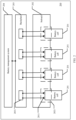
- FIG. 3 An example way of the power conducting circuit, the sampling circuit, and the equalizer circuit integrated into the backplane 203 may be shown in FIG. 3 .
- the battery cells 201 are connected in series through the power circuit and connected to a total positive busbar and a total negative busbar; and the sampling circuit and the equalizer circuit are separately connected with each battery cell 201, so as to collect parameters, such as a voltage, of the battery cell 201 and send the parameters to a sampling chip circuit of the battery management system BMS, so that the BMS can manage the energy storage system including the battery cells 201.
- the BMS 204 may manage the energy storage system in the following specific manner: when an output voltage of the energy storage system 200 is lower than a preset load value, the BMS 204 increases the output voltage of the energy storage system 200 to the preset load value (that is, the BMS 204 boosts the energy storage system 200); when the output voltage of the energy storage system is higher than the preset load value, the BMS 204 reduces the output voltage of the energy storage system 200 to the preset load value (that is, the BMS 204 steps down the energy storage system); and when the output voltage of the energy storage system 200 matches the preset load value, the BMS 204 supports a load by using a direct connect mode.
- a hot-pluggable connection may also be formed between the BMS 204 and the backplane. This can facilitate convenience of maintaining the BMS.
- a bypass switch is added for each battery cell in the power circuit integrated into the backplane 201 (herein the power circuit can be referred to as a battery cell branch), and then the battery cell 201 is connected to the backplane 203 through a provided battery cell slot 2021 in the subrack 202 (that is, when the second power terminal 2011 is docked with the first power terminal 2031), the bypass switch is opened (to avoid a short circuit), and a switch of the battery cell branch is closed, realizing communication of the battery cell with the power circuit, the sampling circuit, and the equalizer circuit; and when the battery cell 201 is not connected to the backplane 203 (that is, when the second power terminal 2011 is not docked with the first power terminal 2031) or the battery cell 201 fails, the switch of the battery cell branch is opened, and the bypass switch is closed (to achieve circuit conductivity and prevent an open circuit).
- a specific circuit example thereof may be shown in FIG. 4 .
- a switch K1 in FIG. 4 is a bypass switch configured for a battery cell 1
- a switch K2 is a bypass switch configured for a battery cell 2
- a switch K3 is a battery cell branch switch configured for the battery cell 1
- a switch K4 is a battery cell branch switch configured for the battery cell 2.
- both the battery cell 1 and the battery cell 2 function properly (to be specific, both the battery cell 1 and the battery cell 2 are inserted into battery cell slots, and supply power normally), the switch K1 and the switch K2 are opened, and the switch K3 and the switch K4 are closed; provided that the battery cell 1 fails or the battery cell branch of the battery cell 1 fails for example, being short-circuited, while the battery cell 2 functions properly, the switch K1 is closed, the switch K3 is opened, the switch K2 is opened, and the switch K4 is closed; and provided that the battery cell 2 fails or the battery cell branch of the battery cell 2 fails, for example, being short-circuited, while the battery cell 1 functions properly, the switch K2 is closed, the switch K4 is opened, the switch K1 is opened, and the switch K3 is closed.
- the second power terminal 2011 of the battery cell 201 may be designed as a plug-in terminal male connector welded to a cover 2012 of the battery cell 201, and the first power terminal 2031 of the backplane 203 is designed as a plug-in terminal female connector welded to the backplane 203; or, the second power terminal 2011 of the battery cell 201 may be designed as a plug-in terminal male connector welded to an electrode pole of the battery cell, and the first power terminal 2031 of the backplane 203 is designed as a plug-in terminal female connector welded to the backplane 203; or, the second power terminal 2011 of the battery cell 201 may be designed as a plug-in terminal female connector welded to a cover of the battery cell, and the first power terminal 2031 of the backplane 203 is designed as a plug-in terminal male connector welded to the backplane 203;
- the disclosed system, apparatus, and method may be implemented in other manners.
- the described apparatus implementation is merely an example.
- the unit division is merely logical function division and may be other division in actual implementation.
- a plurality of units or components may be combined or integrated into another system, or some features may be ignored or not performed.
- the displayed or discussed mutual couplings or direct couplings or communication connections may be implemented by using some interfaces.
- the indirect couplings or communication connections between the apparatuses or units may be implemented in electrical, mechanical, or other forms.
- the units described as separate parts may or may not be physically separate, and parts displayed as units may or may not be physical units, may be located in one position, or may be distributed on a plurality of network units. Some or all of the units may be selected based on actual requirements to achieve the objectives of the solutions of the implementations.
- functional units in the implementations of this application may be integrated into one processing unit, or each of the units may exist alone physically, or two or more units are integrated into one unit.
- the integrated unit may be implemented in a form of hardware, or may be implemented in a form of a software functional unit.
- the integrated unit When the integrated unit is implemented in the form of a software functional unit and sold or used as an independent product, the integrated unit may be stored in a computer-readable storage medium. Based on such an understanding, the technical solutions of this application essentially, or the part contributing to the prior art, or all or some of the technical solutions may be implemented in the form of a software product.
- the software product is stored in a storage medium and includes several instructions for instructing a computer device (which may be a personal computer, a server, or a network device) to perform all or some of the steps of the methods described in the implementations of this application.
- the foregoing storage medium includes: any medium that can store program code, such as a USB flash drive, a removable hard disk, a read-only memory (Read-Only Memory, ROM), a random access memory (Random Access Memory, RAM), a magnetic disk, or an optical disc.
- program code such as a USB flash drive, a removable hard disk, a read-only memory (Read-Only Memory, ROM), a random access memory (Random Access Memory, RAM), a magnetic disk, or an optical disc.
Landscapes
- Chemical & Material Sciences (AREA)
- Chemical Kinetics & Catalysis (AREA)
- Electrochemistry (AREA)
- General Chemical & Material Sciences (AREA)
- Engineering & Computer Science (AREA)
- Manufacturing & Machinery (AREA)
- Power Engineering (AREA)
- Microelectronics & Electronic Packaging (AREA)
- Materials Engineering (AREA)
- Aviation & Aerospace Engineering (AREA)
- Charge And Discharge Circuits For Batteries Or The Like (AREA)
- Secondary Cells (AREA)
Description
- This application relates to the battery field, and in particular, to an energy storage system.
- With the development of lithium-ion battery technologies, lithium-ion batteries have become widely used in fields such as communication power supplies, data centers, microgrid energy storage, and electric vehicles. As processes and techniques mature, capacity of a single battery cell is gradually increasing. At present, large-capacity battery cells in the industry have reached about 300 ampere-hours (Ah). However, this capacity is still small compared with that of lead-acid batteries. Therefore, a plurality of battery cells usually need to be connected in series and parallel in application. At present, when electric vehicles and energy storage use lithium batteries, a usual practice is to first connect battery cells in series and parallel to combine into a standard pack module, and then install the standard pack module into installation space such as an energy storage cabinet, a rack, or an electric vehicle chassis, with power and sampling harnesses separately connected to form a backup power supply system to provide power to the outside.
- A communication energy storage application is used as an example. After lithium-ion batteries are screened by specifications, selected batteries are usually connected in series and parallel to form a pack module of 15 to 16 strings (lithium iron phosphate). The pack module contains components such as a sampling harness, a power connection bar, an insulating sheet, and a fixing bracket; then a battery management system (battery management system, BMS) control board and the pack module are combined into an integrated 48-volt (V) battery product. In practical application, the 48 V battery product is installed in a cabinet with a communication line and a power line connected.
- In this solution, battery cells need to be assembled into a pack, and then the pack is combined with a BMS to form a battery module. Therefore, a large quantity of protective and fixing apparatuses need to be configured, thereby increasing costs and production cycles.
-
JP2013126343 -
KR20180050156 -
US2016211698 relates to battery modules having detection connectors and related systems. In particular, the document provides a battery module including a battery module connector configured to engage with a backplane connector on a backplane board associated with an uninterruptible power supply (UPS). When the battery module connector is engaged with the backplane connector a circuit is completed that instantaneously indicates to the UPS that the battery module is connected. When the battery module connector is disengaged from the backplane connector the circuit is opened and instantaneously indicates to the UPS that the battery module is disconnected. -
JP 2002117821A -
WO 2011 /025937 A2 -
US 2016/226108 A1 relates to battery pack including inserted type BMS assembly. - Implementations of this application provide an energy storage system, to simplify production of lithium battery packs, improve installation efficiency of lithium batteries, reduce costs, and improve system reliability.
- The invention has been defined in the independent claims. Further specific technical features have been defined in the dependent claims.
- According to a first aspect, an implementation of this application provides an energy storage system, specifically including: battery cells, a subrack, a backplane, and a battery management system (battery management system, BMS), where a plurality of battery cell slots are provided in the subrack, so that the battery cells can be connected to the backplane through the battery cell slots; the backplane is installed in the subrack, a first power terminal is provided at a position corresponding to the battery cell slot on the backplane, and a plug-in power terminal is formed by a second power terminal of the battery cell together with the first power terminal through the battery cell slot; a power circuit, a sampling circuit, and an equalizer circuit are integrated into the backplane, and the power circuit, the sampling circuit, and the equalizer circuit are connected after the second power terminal is plugged and docked with the first power terminal; and the BMS is connected to the backplane for managing the energy storage system.
- In this implementation, the battery cell slots provided in the subrack of the energy storage system may be determined depending on a specific application scenario. For example, if the application scenario of the energy storage system requires the energy storage system to output a voltage of 48 V, the subrack may be designed to provide 18 or more battery cell slots. The BMS may further communicate with a host computer. A current generated by discharge of the battery cells is connected by the power circuit to positive and negative busbars; while the sampling circuit and the equalizer circuit collect parameters, such as a voltage, of each of the battery cells, and support discharge of each of the battery cells without connection to the positive and negative busbars.
- In the technical solution provided by this implementation of this application, the battery cells no longer need to be assembled into a pack and then fixedly installed, but directly form a pluggable power terminal with the backplane, so as to realize pluggable installation of the battery cells. This can effectively simplify production of lithium battery packs, improve efficiency of lithium battery installation and reduce costs.
- In the energy storage system, a bypass switch is added to the power circuit integrated into the backplane (herein the power circuit can be referred to as a battery cell branch), and then the battery cell is connected to the backplane through the provided battery cell slot in the subrack (that is, when the second power terminal is docked with the first power terminal), the bypass switch is opened (to avoid a short circuit), and a switch of the battery cell branch is closed, realizing communication of the battery cell with the power circuit, the sampling circuit, and the equalizer circuit; and when the battery cell is not connected to the backplane (that is, when the second power terminal is not docked with the first power terminal) or the battery cell fails, the switch of the battery cell branch is opened, and the bypass switch is closed (to achieve circuit conductivity and prevent an open circuit). In this way, it can be implemented that, when a battery cell fails, the system automatically bypasses the failed battery cell and outputs corresponding power through boosting by the BMS. Therefore, the system can function properly, and maintenance personnel can directly replace the failed battery cell instead of cutting off power supply and replacing an entire battery cell combination, thereby enabling the system to provide highly reliable power supply and reducing maintenance costs.
- Optionally, the BMS may manage the energy storage system in the following specific manner: when an output voltage of the energy storage system is lower than a preset load value, the BMS increases the output voltage of the energy storage system to the preset load value (that is, the BMS boosts the energy storage system); when the output voltage of the energy storage system is higher than the preset load value, the BMS reduces the output voltage of the energy storage system to the preset load value (that is, the BMS steps down the energy storage system); and when the output voltage of the energy storage system matches the preset load value, the BMS supports a load by using a direct connect mode. This can ensure a consistent output voltage of the energy storage system during application, thereby increasing reliability of the energy storage system.
- Optionally, to enable the battery cell to be docked with the backplane in a hot-pluggable manner, the second power terminal of the battery cell may be designed as a plug-in terminal male connector welded to a cover of the battery cell, and the first power terminal of the backplane is designed as a plug-in terminal female connector welded to the backplane; or, the second power terminal of the battery cell may be designed as a plug-in terminal male connector welded to an electrode pole of the battery cell, and the first power terminal of the backplane is designed as a plug-in terminal female connector welded to the backplane; or, the second power terminal of the battery cell may be designed as a plug-in terminal female connector welded to a cover of the battery cell, and the first power terminal of the backplane is designed as a plug-in terminal male connector welded to the backplane; or, the second power terminal of the battery cell may be designed as a plug-in terminal female connector welded to an electrode pole of the battery cell, and the first power terminal of the backplane is designed as a plug-in terminal male connector welded to the backplane. The specific situation is not limited herein.
- According to the claimed invention, a connection between the BMS and the backplane is also hot-pluggable. This can facilitate convenience of maintaining the BMS.
- Optionally, the battery cell may be a combined battery module, or a single battery cell, as long as the battery cell can be hot-pluggable to the energy storage system.
-
-
FIG. 1 is a schematic diagram of assembling of a battery module; -
FIG. 2 is a schematic diagram of an implementation of an energy storage system according to an implementation of this application; -
FIG. 3 is a schematic diagram of a backplane integrated circuit according to an implementation of this application; -
FIG. 4 is a schematic diagram of a bypass switch and a battery cell branch according to an implementation of this application; and -
FIG. 5 is a schematic diagram of a cover of a battery cell according to an implementation of this application. - To make the objectives, technical solutions, and advantages of this invention clearer, the following further describes various implementations in detail with reference to the accompanying drawings. The implementations described below are not all claimed, they are included to help understanding the context of the invention. While the description refers to various implementations, the embodiments of the invention are those which comprise at least all the features of an independent claim. Any implementation which does not fall within the scope of the claims does not form part of the invention, but rather included as an illustrative example that is useful for understanding the invention.
- Implementations of this application provide an energy storage system, to improve reliability of an energy storage system as backup power and flexibility of installation and configuration, thereby simplifying production of lithium battery packs, improving installation efficiency of lithium batteries and reducing costs.
- In the specification, claims, and accompanying drawings of this application, the terms "first", "second", "third", "fourth", and so on (if existent) are intended to distinguish between similar objects but do not necessarily indicate a specific order or sequence. It should be understood that the data termed in such a way are interchangeable in proper circumstances so that the implementations of the present disclosure described herein can be implemented in other orders than the order illustrated or described herein. Moreover, the terms "include", "contain" and any other variants mean to cover the non-exclusive inclusion, for example, a process, method, system, product, or device that includes a list of steps or units is not necessarily limited to those units, but may include other units not expressly listed or inherent to such a process, method, system, product, or device.
- With the development of lithium-ion battery technologies, lithium-ion batteries have become widely used in fields such as communication power supplies, data centers, microgrid energy storage, and electric vehicles. As processes and techniques mature, capacity of a single battery cell is gradually increasing. At present, large-capacity battery cells in the industry have reached about 300 ampere-hours (Ah). However, this capacity is still small compared with that of lead-acid batteries. Therefore, a plurality of battery cells usually need to be connected in series and parallel in application. As shown in
FIG. 1 , for current lithium batteries, a usual practice is to first connect battery cells in series and parallel to combine into a standard pack module; and then install the standard pack module into installation space such as an energy storage cabinet, a rack, or an electric vehicle chassis, with power and sampling harnesses separately connected to form a backup power supply system to provide power to the outside. A communication energy storage application is used as an example. After lithium-ion batteries are screened by specifications, selected batteries are usually connected in series and parallel to form a pack module of 15 to 16 strings. The pack module contains components such as a sampling harness, a power connection bar, an insulating sheet, and a fixing bracket. Then a battery management system (battery management system, BMS) control board and the pack module are combined into an integrated 48 V battery product. In practical application, the 48 V battery product is installed in a cabinet with a communication line and a power line connected. In this solution, battery cells need to be assembled into a pack, and then the pack is combined with a BMS to form a battery module. Therefore, a large quantity of protective and fixing apparatuses need to be configured, thereby increasing costs and production cycles. - An implementation of this application provides the following energy storage system, specifically including: battery cells, a subrack, a backplane, and a battery management system (battery management system, BMS), where a plurality of battery cell slots are provided in the subrack, so that the battery cells can be connected to the backplane through the battery cell slots; the backplane is installed in the subrack, a first power terminal is provided at a position corresponding to the battery cell slot on the backplane, and a plug-in power terminal is formed by a second power terminal of the battery cell together with the first power terminal through the battery cell slot; a power circuit, a sampling circuit, and an equalizer circuit are integrated into the backplane, and the power circuit, the sampling circuit, and the equalizer circuit are connected after the second power terminal is plugged and docked with the first power terminal; and the BMS is connected to the backplane for managing the energy storage system.
- Referring to
FIG. 2 , anenergy storage system 200 specifically includes:battery cells 201, asubrack 202, abackplane 203, and aBMS 204. A plurality ofbattery cell slots 2021 are provided in thesubrack 202, so that thebattery cells 201 can be connected to thebackplane 203 through thebattery cell slots 2021. Thebackplane 203 is installed in thesubrack 202, afirst power terminal 2031 is provided at a position corresponding to thebattery cell slot 2021 on thebackplane 203, and a plug-in power terminal is formed by asecond power terminal 2011 of thebattery cell 201 together with thefirst power terminal 2031. A power circuit, a sampling circuit, and an equalizer circuit are further integrated into thebackplane 203, and the power circuit, the sampling circuit, and the equalizer circuit are connected to form a power supply circuit when thesecond power terminal 2011 is plugged and docked with thefirst power terminal 2031; and theBMS 204 is connected to thebackplane 203 for managing theenergy storage system 200. - It can be understood that an example way of the power conducting circuit, the sampling circuit, and the equalizer circuit integrated into the
backplane 203 may be shown inFIG. 3 . Thebattery cells 201 are connected in series through the power circuit and connected to a total positive busbar and a total negative busbar; and the sampling circuit and the equalizer circuit are separately connected with eachbattery cell 201, so as to collect parameters, such as a voltage, of thebattery cell 201 and send the parameters to a sampling chip circuit of the battery management system BMS, so that the BMS can manage the energy storage system including thebattery cells 201. TheBMS 204 may manage the energy storage system in the following specific manner: when an output voltage of theenergy storage system 200 is lower than a preset load value, theBMS 204 increases the output voltage of theenergy storage system 200 to the preset load value (that is, theBMS 204 boosts the energy storage system 200); when the output voltage of the energy storage system is higher than the preset load value, theBMS 204 reduces the output voltage of theenergy storage system 200 to the preset load value (that is, theBMS 204 steps down the energy storage system); and when the output voltage of theenergy storage system 200 matches the preset load value, theBMS 204 supports a load by using a direct connect mode. This can ensure a consistent output voltage of theenergy storage system 200 during application, thereby increasing reliability of theenergy storage system 200. According to the claimed invention, a hot-pluggable connection may also be formed between theBMS 204 and the backplane. This can facilitate convenience of maintaining the BMS. - It can be understood that a bypass switch is added for each battery cell in the power circuit integrated into the backplane 201 (herein the power circuit can be referred to as a battery cell branch), and then the
battery cell 201 is connected to thebackplane 203 through a providedbattery cell slot 2021 in the subrack 202 (that is, when thesecond power terminal 2011 is docked with the first power terminal 2031), the bypass switch is opened (to avoid a short circuit), and a switch of the battery cell branch is closed, realizing communication of the battery cell with the power circuit, the sampling circuit, and the equalizer circuit; and when thebattery cell 201 is not connected to the backplane 203 (that is, when thesecond power terminal 2011 is not docked with the first power terminal 2031) or thebattery cell 201 fails, the switch of the battery cell branch is opened, and the bypass switch is closed (to achieve circuit conductivity and prevent an open circuit). In this way, it can be implemented that, when a battery cell fails, the system automatically bypasses the failed battery cell and outputs corresponding power through boosting by the BMS. Therefore, the system can function properly, and maintenance personnel can directly replace the failed battery cell instead of cutting off power supply and replacing an entire battery cell combination, thereby enabling the system to provide highly reliable power supply and reducing maintenance costs. A specific circuit example thereof may be shown inFIG. 4 . A switch K1 inFIG. 4 is a bypass switch configured for abattery cell 1, a switch K2 is a bypass switch configured for abattery cell 2, a switch K3 is a battery cell branch switch configured for thebattery cell 1, and a switch K4 is a battery cell branch switch configured for thebattery cell 2. When both thebattery cell 1 and thebattery cell 2 function properly (to be specific, both thebattery cell 1 and thebattery cell 2 are inserted into battery cell slots, and supply power normally), the switch K1 and the switch K2 are opened, and the switch K3 and the switch K4 are closed; provided that thebattery cell 1 fails or the battery cell branch of thebattery cell 1 fails for example, being short-circuited, while thebattery cell 2 functions properly, the switch K1 is closed, the switch K3 is opened, the switch K2 is opened, and the switch K4 is closed; and provided that thebattery cell 2 fails or the battery cell branch of thebattery cell 2 fails, for example, being short-circuited, while thebattery cell 1 functions properly, the switch K2 is closed, the switch K4 is opened, the switch K1 is opened, and the switch K3 is closed. - In the energy storage system shown in
FIG. 2 , to enable the battery cell 201 to be docked with the backplane 203 in a hot-pluggable manner, the second power terminal 2011 of the battery cell 201 may be designed as a plug-in terminal male connector welded to a cover 2012 of the battery cell 201, and the first power terminal 2031 of the backplane 203 is designed as a plug-in terminal female connector welded to the backplane 203; or, the second power terminal 2011 of the battery cell 201 may be designed as a plug-in terminal male connector welded to an electrode pole of the battery cell, and the first power terminal 2031 of the backplane 203 is designed as a plug-in terminal female connector welded to the backplane 203; or, the second power terminal 2011 of the battery cell 201 may be designed as a plug-in terminal female connector welded to a cover of the battery cell, and the first power terminal 2031 of the backplane 203 is designed as a plug-in terminal male connector welded to the backplane 203; or, the second power terminal 2011 of the battery cell 201 may be designed as a plug-in terminal female connector welded to an electrode pole of the battery cell, and the first power terminal 2031 of the backplane 203 is designed as a plug-in terminal male connector welded to the backplane 203. Thecover 2012 of thebattery cell 201 may be shown inFIG. 5 . Thecover 2012 includes apositive electrode pole 2012a and anegative electrode pole 2012b, and an explosion-proof valve 2012c. - It may be clearly understood by a person skilled in the art that, for the purpose of convenient and brief description, for a detailed working process of the foregoing system, apparatus, and unit, refer to a corresponding process in the foregoing method implementations, and details are not described herein again.
- In the several implementations provided in this application, it should be understood that the disclosed system, apparatus, and method may be implemented in other manners. For example, the described apparatus implementation is merely an example. For example, the unit division is merely logical function division and may be other division in actual implementation. For example, a plurality of units or components may be combined or integrated into another system, or some features may be ignored or not performed. In addition, the displayed or discussed mutual couplings or direct couplings or communication connections may be implemented by using some interfaces. The indirect couplings or communication connections between the apparatuses or units may be implemented in electrical, mechanical, or other forms.
- The units described as separate parts may or may not be physically separate, and parts displayed as units may or may not be physical units, may be located in one position, or may be distributed on a plurality of network units. Some or all of the units may be selected based on actual requirements to achieve the objectives of the solutions of the implementations.
- In addition, functional units in the implementations of this application may be integrated into one processing unit, or each of the units may exist alone physically, or two or more units are integrated into one unit. The integrated unit may be implemented in a form of hardware, or may be implemented in a form of a software functional unit.
- When the integrated unit is implemented in the form of a software functional unit and sold or used as an independent product, the integrated unit may be stored in a computer-readable storage medium. Based on such an understanding, the technical solutions of this application essentially, or the part contributing to the prior art, or all or some of the technical solutions may be implemented in the form of a software product. The software product is stored in a storage medium and includes several instructions for instructing a computer device (which may be a personal computer, a server, or a network device) to perform all or some of the steps of the methods described in the implementations of this application. The foregoing storage medium includes: any medium that can store program code, such as a USB flash drive, a removable hard disk, a read-only memory (Read-Only Memory, ROM), a random access memory (Random Access Memory, RAM), a magnetic disk, or an optical disc.
- The scope of protection is defined by the appended claims.
Claims (3)
- An energy storage system, comprising:multiple battery cells (201), a subrack (202), a backplane (203), and a battery management system, BMS (204), whereinthe subrack comprises a plurality of battery cell slots such that the battery cells are connected to the backplane through the battery cell slots;the backplane is installed in the subrack, and is configured to provide a first power terminal at a position corresponding to each battery cell slot such that a plug-in power terminal is formed by a second power terminal of the battery cell together with the first power terminal;a power circuit, a sampling circuit, and an equalizer circuit are integrated into the backplane such that when the second power terminal is plugged and docked with the first power terminal, the battery cell is connected to the power circuit, the sampling circuit, and the equalizer circuit, wherein the power circuit is configured to connect a current generated by discharge of the battery cells to positive and negative busbars to which the energy storage system in connected, and the sampling circuit and the equalizer circuit are configured to collect parameters of each of the battery cells, and support discharge of each of the battery cells without connection to the positive and negative busbars;the BMS is connected to the backplane for managing the energy storage system, wherein the BMS and the backplane are connected by plugging;wherein:
the power circuit includes, for each battery cell, a bypass switch and a branch switch, and the power circuit is configured such that:when the second power terminal is plugged and docked with the first power terminal, the bypass switch is opened and the branch switch is closed; andwhen the second power terminal is not plugged and docked with the first power terminal or the battery cell fails, the bypass switch is closed and the branch switch is opened. - The energy storage system according to claim 1, wherein the BMS is configured to manage the energy storage system specifically in the following way:when an output voltage of the energy storage system is lower than a preset load value, the BMS is configured to increase the output voltage of the energy storage system to the preset load value;when the output voltage of the energy storage system is higher than the preset load value, the BMS is configured to decrease the output voltage of the energy storage system to the preset load value; andwhen the output voltage of the energy storage system is equal to the preset load value, the BMS is configured to support the load by using a direct connect mode.
- The energy storage system according to claim 1 or 2, wherein:the second power terminal of the battery cell is a plug-in terminal male connector welded to a cover, and a first power terminal of the backplane is a welded plug-in terminal female connector;
orthe second power terminal of the battery cell is a plug-in terminal male connector welded to an electrode pole, and the first power terminal of the backplane is a welded plug-in terminal female connector.
Applications Claiming Priority (2)
| Application Number | Priority Date | Filing Date | Title |
|---|---|---|---|
| CN201811639775.8A CN109786599B (en) | 2018-12-29 | 2018-12-29 | an energy storage system |
| PCT/CN2019/106657 WO2020134214A1 (en) | 2018-12-29 | 2019-09-19 | Energy storage system |
Publications (3)
| Publication Number | Publication Date |
|---|---|
| EP3893289A1 EP3893289A1 (en) | 2021-10-13 |
| EP3893289A4 EP3893289A4 (en) | 2022-04-06 |
| EP3893289B1 true EP3893289B1 (en) | 2024-07-31 |
Family
ID=66499106
Family Applications (1)
| Application Number | Title | Priority Date | Filing Date |
|---|---|---|---|
| EP19904884.4A Active EP3893289B1 (en) | 2018-12-29 | 2019-09-19 | Energy storage system |
Country Status (4)
| Country | Link |
|---|---|
| US (1) | US11581588B2 (en) |
| EP (1) | EP3893289B1 (en) |
| CN (1) | CN109786599B (en) |
| WO (1) | WO2020134214A1 (en) |
Families Citing this family (10)
| Publication number | Priority date | Publication date | Assignee | Title |
|---|---|---|---|---|
| CN109786599B (en) * | 2018-12-29 | 2021-08-31 | 华为数字技术(苏州)有限公司 | an energy storage system |
| US20250096599A1 (en) * | 2019-09-19 | 2025-03-20 | Junkyeong KIM | Elevator emergency power systems and methods |
| US20220029431A1 (en) * | 2020-07-23 | 2022-01-27 | Aurora Flight Sciences Corporation, a subsidiary of The Boeing Company | Switchable Battery Management System |
| CN114759631A (en) * | 2022-04-15 | 2022-07-15 | 华为数字能源技术有限公司 | Power module, insert frame and electrical power generating system |
| AT526056B1 (en) * | 2022-09-30 | 2023-11-15 | Avl List Gmbh | Modular storage device and method for equipping the same |
| GB2624374B (en) * | 2022-11-09 | 2024-11-20 | Power Concepts Nz Ltd | Modular power system |
| CN116094011A (en) * | 2023-01-18 | 2023-05-09 | 华为数字能源技术有限公司 | Energy storage system |
| US20240405478A1 (en) * | 2023-05-30 | 2024-12-05 | Vertiv Corporation | Battery cabinet with blind mate connectors |
| US12588157B2 (en) | 2023-11-08 | 2026-03-24 | Power Concepts Nz Limited | Modular power system |
| CN118348460B (en) * | 2024-06-14 | 2024-09-24 | 南京君海数能科技有限公司 | String detection device and detection method thereof |
Citations (3)
| Publication number | Priority date | Publication date | Assignee | Title |
|---|---|---|---|---|
| JP2002117821A (en) * | 2000-10-04 | 2002-04-19 | Nippon Telegr & Teleph Corp <Ntt> | Storage battery storage cabinet and storage battery storage connection method |
| WO2011025937A2 (en) * | 2009-08-28 | 2011-03-03 | The Charles Stark Draper Laboratory, Inc. | High-efficiency battery equalization for charging and discharging |
| US20160226108A1 (en) * | 2013-09-24 | 2016-08-04 | Lg Chem, Ltd. | Battery pack including inserted type bms assembly |
Family Cites Families (23)
| Publication number | Priority date | Publication date | Assignee | Title |
|---|---|---|---|---|
| US7126378B2 (en) * | 2003-12-17 | 2006-10-24 | Rambus, Inc. | High speed signaling system with adaptive transmit pre-emphasis |
| TW200913433A (en) * | 2007-09-10 | 2009-03-16 | J Tek Inc | Scattered energy storage control system |
| JP2013126343A (en) * | 2011-12-16 | 2013-06-24 | Hitachi Ltd | Power storage system with storage device |
| CN102610776B (en) * | 2012-03-13 | 2015-01-21 | 华为技术有限公司 | Lithium battery connection structure |
| WO2014207421A1 (en) * | 2013-06-26 | 2014-12-31 | Tws (Macau Commercial Offshore) Limited | Energy storage system |
| KR102284483B1 (en) * | 2014-12-02 | 2021-08-02 | 삼성에스디아이 주식회사 | Battery Module and Driving Method Thereof |
| US10153658B2 (en) * | 2015-01-21 | 2018-12-11 | Eaton Intelligent Power Limited | Battery modules having detection connectors and related systems |
| US10749430B2 (en) * | 2015-03-13 | 2020-08-18 | Positec Power Tools (Suzhou) Co., Ltd. | Power transmission apparatus and control method therefor, and power supply system |
| CN106100068B (en) * | 2016-08-10 | 2018-09-14 | 青海绿草地新能源科技有限公司 | A kind of battery pack detachable mobile power |
| CN206510769U (en) * | 2016-08-23 | 2017-09-22 | 新能瑞驰(北京)能源技术有限公司 | A kind of intelligent power battery pack and new-energy automobile |
| CN106114275B (en) * | 2016-08-23 | 2019-11-08 | 新能瑞驰(北京)能源技术有限公司 | A kind of intelligent power battery pack and new-energy automobile |
| CN106356927B (en) * | 2016-09-19 | 2018-11-30 | 华中科技大学 | A kind of lithium battery group SOC balance system and method |
| KR102599399B1 (en) * | 2016-11-04 | 2023-11-08 | 한국전력공사 | Apparatus for managing energy storage system and method for operating the same |
| CN106740228B (en) | 2017-01-13 | 2019-06-04 | 宁德时代新能源科技股份有限公司 | Voltage consistency detection method and device and voltage equalization method and device |
| CN206759134U (en) * | 2017-04-27 | 2017-12-15 | 北京新能源汽车股份有限公司 | Power battery and electric automobile |
| US10586961B2 (en) * | 2017-05-30 | 2020-03-10 | Artisan Vehicle Systems Inc. | Multi-modular battery system |
| US10697417B2 (en) * | 2017-10-06 | 2020-06-30 | Briggs & Stratton Corporation | Battery connections for battery start of internal combustion engines |
| CN107742914A (en) * | 2017-11-15 | 2018-02-27 | 王晓秋 | Integrated Service Digital Network news technology between controller and lithium battery module BMS |
| CN107878239A (en) * | 2017-11-22 | 2018-04-06 | 安徽零度新能源科技有限公司 | A kind of dynamic lithium battery management system |
| CN108482149A (en) * | 2018-03-22 | 2018-09-04 | 普汽新能(北京)科技有限公司 | A method of assembling batteries of electric automobile group with high-low pressure integrated circuit board |
| JP7003855B2 (en) * | 2018-07-05 | 2022-01-21 | 株式会社オートネットワーク技術研究所 | Power system |
| EP3657571A1 (en) * | 2018-11-26 | 2020-05-27 | Aptiv Technologies Limited | Battery module |
| CN109786599B (en) * | 2018-12-29 | 2021-08-31 | 华为数字技术(苏州)有限公司 | an energy storage system |
-
2018
- 2018-12-29 CN CN201811639775.8A patent/CN109786599B/en active Active
-
2019
- 2019-09-19 WO PCT/CN2019/106657 patent/WO2020134214A1/en not_active Ceased
- 2019-09-19 EP EP19904884.4A patent/EP3893289B1/en active Active
-
2021
- 2021-06-25 US US17/358,907 patent/US11581588B2/en active Active
Patent Citations (3)
| Publication number | Priority date | Publication date | Assignee | Title |
|---|---|---|---|---|
| JP2002117821A (en) * | 2000-10-04 | 2002-04-19 | Nippon Telegr & Teleph Corp <Ntt> | Storage battery storage cabinet and storage battery storage connection method |
| WO2011025937A2 (en) * | 2009-08-28 | 2011-03-03 | The Charles Stark Draper Laboratory, Inc. | High-efficiency battery equalization for charging and discharging |
| US20160226108A1 (en) * | 2013-09-24 | 2016-08-04 | Lg Chem, Ltd. | Battery pack including inserted type bms assembly |
Non-Patent Citations (1)
| Title |
|---|
| QI JIAN ET AL: "Review of battery cell balancing techniques", 2014 AUSTRALASIAN UNIVERSITIES POWER ENGINEERING CONFERENCE (AUPEC), ACPE, 28 September 2014 (2014-09-28), pages 1 - 6, XP032691848, DOI: 10.1109/AUPEC.2014.6966514 * |
Also Published As
| Publication number | Publication date |
|---|---|
| CN109786599B (en) | 2021-08-31 |
| US20210328276A1 (en) | 2021-10-21 |
| US11581588B2 (en) | 2023-02-14 |
| CN109786599A (en) | 2019-05-21 |
| EP3893289A1 (en) | 2021-10-13 |
| WO2020134214A1 (en) | 2020-07-02 |
| EP3893289A4 (en) | 2022-04-06 |
Similar Documents
| Publication | Publication Date | Title |
|---|---|---|
| EP3893289B1 (en) | Energy storage system | |
| JP2023516735A (en) | Apparatus, system and method for batteries | |
| US9812689B2 (en) | Community energy storage system with battery bank deactivation | |
| US20190356159A1 (en) | Rack-mounted ups device for data centers | |
| US10932388B1 (en) | Pluggable power distribution units for modular edge power systems | |
| US20130099574A1 (en) | System and method for multiple power supplies | |
| CN112600264B (en) | Control method and system of parallel battery packs, electronic equipment and vehicle | |
| CN106505694A (en) | A kind of management system of intelligent battery group and control method | |
| US10193357B2 (en) | Energy storage system | |
| CN107425572A (en) | A kind of energy intelligent management system of power battery pack | |
| CN105048607A (en) | Novel multi-output lithium battery power supply device and control method thereof | |
| US20240421592A1 (en) | Hot Swappable Monoblock Battery | |
| US20240405478A1 (en) | Battery cabinet with blind mate connectors | |
| CN220570346U (en) | Power storage device, energy storage unit and power supply system with multiple storage battery modules connected in series | |
| CN216649294U (en) | Lithium battery system of data center and data center | |
| CN210744092U (en) | Short-plate battery isolation device for retired power battery | |
| CN104753099B (en) | A kind of electric power system and method for controlling power supply | |
| CN114039403A (en) | Lithium battery system and data center | |
| CN216564621U (en) | UPS backup power supply | |
| CN220857678U (en) | Energy storage system | |
| US20240178464A1 (en) | Battery device and battery management system | |
| CN114186171B (en) | A DC guard power supply system and a method for identifying the state of a battery circuit | |
| KR20260033134A (en) | Battery system including power supply and operating method thereof | |
| Lansburg et al. | Innovative modular Li-ion battery system delivers high power support for data center UPS installations | |
| US7763992B2 (en) | Universal interface for battery charger |
Legal Events
| Date | Code | Title | Description |
|---|---|---|---|
| STAA | Information on the status of an ep patent application or granted ep patent |
Free format text: STATUS: THE INTERNATIONAL PUBLICATION HAS BEEN MADE |
|
| PUAI | Public reference made under article 153(3) epc to a published international application that has entered the european phase |
Free format text: ORIGINAL CODE: 0009012 |
|
| STAA | Information on the status of an ep patent application or granted ep patent |
Free format text: STATUS: REQUEST FOR EXAMINATION WAS MADE |
|
| 17P | Request for examination filed |
Effective date: 20210708 |
|
| AK | Designated contracting states |
Kind code of ref document: A1 Designated state(s): AL AT BE BG CH CY CZ DE DK EE ES FI FR GB GR HR HU IE IS IT LI LT LU LV MC MK MT NL NO PL PT RO RS SE SI SK SM TR |
|
| RAP1 | Party data changed (applicant data changed or rights of an application transferred) |
Owner name: HUAWEI DIGITAL POWER TECHNOLOGIES CO., LTD. |
|
| A4 | Supplementary search report drawn up and despatched |
Effective date: 20220303 |
|
| DAV | Request for validation of the european patent (deleted) | ||
| DAX | Request for extension of the european patent (deleted) | ||
| RIC1 | Information provided on ipc code assigned before grant |
Ipc: H01M 10/42 20060101ALN20220225BHEP Ipc: H02J 7/00 20060101ALI20220225BHEP Ipc: H01M 10/052 20100101ALI20220225BHEP Ipc: H01M 50/284 20210101ALI20220225BHEP Ipc: H01M 50/249 20210101ALI20220225BHEP Ipc: H01M 50/209 20210101ALI20220225BHEP Ipc: H01M 10/48 20060101ALI20220225BHEP Ipc: H01M 50/258 20210101AFI20220225BHEP |
|
| STAA | Information on the status of an ep patent application or granted ep patent |
Free format text: STATUS: EXAMINATION IS IN PROGRESS |
|
| 17Q | First examination report despatched |
Effective date: 20220926 |
|
| REG | Reference to a national code |
Ref country code: DE Ipc: H01M0050258000 Ref country code: DE Ref legal event code: R079 Ref document number: 602019056360 Country of ref document: DE Free format text: PREVIOUS MAIN CLASS: H01M0002100000 Ipc: H01M0050258000 |
|
| GRAP | Despatch of communication of intention to grant a patent |
Free format text: ORIGINAL CODE: EPIDOSNIGR1 |
|
| STAA | Information on the status of an ep patent application or granted ep patent |
Free format text: STATUS: GRANT OF PATENT IS INTENDED |
|
| RIC1 | Information provided on ipc code assigned before grant |
Ipc: H01M 10/42 20060101ALN20240229BHEP Ipc: H01M 50/244 20210101ALI20240229BHEP Ipc: H02J 7/00 20060101ALI20240229BHEP Ipc: H01M 10/052 20100101ALI20240229BHEP Ipc: H01M 50/284 20210101ALI20240229BHEP Ipc: H01M 50/249 20210101ALI20240229BHEP Ipc: H01M 50/209 20210101ALI20240229BHEP Ipc: H01M 10/48 20060101ALI20240229BHEP Ipc: H01M 50/258 20210101AFI20240229BHEP |
|
| INTG | Intention to grant announced |
Effective date: 20240319 |
|
| GRAS | Grant fee paid |
Free format text: ORIGINAL CODE: EPIDOSNIGR3 |
|
| GRAA | (expected) grant |
Free format text: ORIGINAL CODE: 0009210 |
|
| STAA | Information on the status of an ep patent application or granted ep patent |
Free format text: STATUS: THE PATENT HAS BEEN GRANTED |
|
| AK | Designated contracting states |
Kind code of ref document: B1 Designated state(s): AL AT BE BG CH CY CZ DE DK EE ES FI FR GB GR HR HU IE IS IT LI LT LU LV MC MK MT NL NO PL PT RO RS SE SI SK SM TR |
|
| REG | Reference to a national code |
Ref country code: CH Ref legal event code: EP Ref country code: GB Ref legal event code: FG4D |
|
| REG | Reference to a national code |
Ref country code: DE Ref legal event code: R096 Ref document number: 602019056360 Country of ref document: DE |
|
| REG | Reference to a national code |
Ref country code: IE Ref legal event code: FG4D |
|
| REG | Reference to a national code |
Ref country code: LT Ref legal event code: MG9D |
|
| REG | Reference to a national code |
Ref country code: NL Ref legal event code: MP Effective date: 20240731 |
|
| PG25 | Lapsed in a contracting state [announced via postgrant information from national office to epo] |
Ref country code: PT Free format text: LAPSE BECAUSE OF FAILURE TO SUBMIT A TRANSLATION OF THE DESCRIPTION OR TO PAY THE FEE WITHIN THE PRESCRIBED TIME-LIMIT Effective date: 20241202 |
|
| REG | Reference to a national code |
Ref country code: AT Ref legal event code: MK05 Ref document number: 1709366 Country of ref document: AT Kind code of ref document: T Effective date: 20240731 |
|
| PG25 | Lapsed in a contracting state [announced via postgrant information from national office to epo] |
Ref country code: PT Free format text: LAPSE BECAUSE OF FAILURE TO SUBMIT A TRANSLATION OF THE DESCRIPTION OR TO PAY THE FEE WITHIN THE PRESCRIBED TIME-LIMIT Effective date: 20241202 |
|
| PG25 | Lapsed in a contracting state [announced via postgrant information from national office to epo] |
Ref country code: NO Free format text: LAPSE BECAUSE OF FAILURE TO SUBMIT A TRANSLATION OF THE DESCRIPTION OR TO PAY THE FEE WITHIN THE PRESCRIBED TIME-LIMIT Effective date: 20241031 |
|
| PG25 | Lapsed in a contracting state [announced via postgrant information from national office to epo] |
Ref country code: GR Free format text: LAPSE BECAUSE OF FAILURE TO SUBMIT A TRANSLATION OF THE DESCRIPTION OR TO PAY THE FEE WITHIN THE PRESCRIBED TIME-LIMIT Effective date: 20241101 Ref country code: NL Free format text: LAPSE BECAUSE OF FAILURE TO SUBMIT A TRANSLATION OF THE DESCRIPTION OR TO PAY THE FEE WITHIN THE PRESCRIBED TIME-LIMIT Effective date: 20240731 Ref country code: FI Free format text: LAPSE BECAUSE OF FAILURE TO SUBMIT A TRANSLATION OF THE DESCRIPTION OR TO PAY THE FEE WITHIN THE PRESCRIBED TIME-LIMIT Effective date: 20240731 Ref country code: PL Free format text: LAPSE BECAUSE OF FAILURE TO SUBMIT A TRANSLATION OF THE DESCRIPTION OR TO PAY THE FEE WITHIN THE PRESCRIBED TIME-LIMIT Effective date: 20240731 |
|
| PG25 | Lapsed in a contracting state [announced via postgrant information from national office to epo] |
Ref country code: BG Free format text: LAPSE BECAUSE OF FAILURE TO SUBMIT A TRANSLATION OF THE DESCRIPTION OR TO PAY THE FEE WITHIN THE PRESCRIBED TIME-LIMIT Effective date: 20240731 |
|
| PG25 | Lapsed in a contracting state [announced via postgrant information from national office to epo] |
Ref country code: LV Free format text: LAPSE BECAUSE OF FAILURE TO SUBMIT A TRANSLATION OF THE DESCRIPTION OR TO PAY THE FEE WITHIN THE PRESCRIBED TIME-LIMIT Effective date: 20240731 |
|
| PG25 | Lapsed in a contracting state [announced via postgrant information from national office to epo] |
Ref country code: AT Free format text: LAPSE BECAUSE OF FAILURE TO SUBMIT A TRANSLATION OF THE DESCRIPTION OR TO PAY THE FEE WITHIN THE PRESCRIBED TIME-LIMIT Effective date: 20240731 Ref country code: IS Free format text: LAPSE BECAUSE OF FAILURE TO SUBMIT A TRANSLATION OF THE DESCRIPTION OR TO PAY THE FEE WITHIN THE PRESCRIBED TIME-LIMIT Effective date: 20241130 |
|
| PG25 | Lapsed in a contracting state [announced via postgrant information from national office to epo] |
Ref country code: HR Free format text: LAPSE BECAUSE OF FAILURE TO SUBMIT A TRANSLATION OF THE DESCRIPTION OR TO PAY THE FEE WITHIN THE PRESCRIBED TIME-LIMIT Effective date: 20240731 |
|
| PG25 | Lapsed in a contracting state [announced via postgrant information from national office to epo] |
Ref country code: ES Free format text: LAPSE BECAUSE OF FAILURE TO SUBMIT A TRANSLATION OF THE DESCRIPTION OR TO PAY THE FEE WITHIN THE PRESCRIBED TIME-LIMIT Effective date: 20240731 Ref country code: RS Free format text: LAPSE BECAUSE OF FAILURE TO SUBMIT A TRANSLATION OF THE DESCRIPTION OR TO PAY THE FEE WITHIN THE PRESCRIBED TIME-LIMIT Effective date: 20241031 |
|
| PG25 | Lapsed in a contracting state [announced via postgrant information from national office to epo] |
Ref country code: RS Free format text: LAPSE BECAUSE OF FAILURE TO SUBMIT A TRANSLATION OF THE DESCRIPTION OR TO PAY THE FEE WITHIN THE PRESCRIBED TIME-LIMIT Effective date: 20241031 Ref country code: PL Free format text: LAPSE BECAUSE OF FAILURE TO SUBMIT A TRANSLATION OF THE DESCRIPTION OR TO PAY THE FEE WITHIN THE PRESCRIBED TIME-LIMIT Effective date: 20240731 Ref country code: NO Free format text: LAPSE BECAUSE OF FAILURE TO SUBMIT A TRANSLATION OF THE DESCRIPTION OR TO PAY THE FEE WITHIN THE PRESCRIBED TIME-LIMIT Effective date: 20241031 Ref country code: NL Free format text: LAPSE BECAUSE OF FAILURE TO SUBMIT A TRANSLATION OF THE DESCRIPTION OR TO PAY THE FEE WITHIN THE PRESCRIBED TIME-LIMIT Effective date: 20240731 Ref country code: LV Free format text: LAPSE BECAUSE OF FAILURE TO SUBMIT A TRANSLATION OF THE DESCRIPTION OR TO PAY THE FEE WITHIN THE PRESCRIBED TIME-LIMIT Effective date: 20240731 Ref country code: IS Free format text: LAPSE BECAUSE OF FAILURE TO SUBMIT A TRANSLATION OF THE DESCRIPTION OR TO PAY THE FEE WITHIN THE PRESCRIBED TIME-LIMIT Effective date: 20241130 Ref country code: HR Free format text: LAPSE BECAUSE OF FAILURE TO SUBMIT A TRANSLATION OF THE DESCRIPTION OR TO PAY THE FEE WITHIN THE PRESCRIBED TIME-LIMIT Effective date: 20240731 Ref country code: GR Free format text: LAPSE BECAUSE OF FAILURE TO SUBMIT A TRANSLATION OF THE DESCRIPTION OR TO PAY THE FEE WITHIN THE PRESCRIBED TIME-LIMIT Effective date: 20241101 Ref country code: FI Free format text: LAPSE BECAUSE OF FAILURE TO SUBMIT A TRANSLATION OF THE DESCRIPTION OR TO PAY THE FEE WITHIN THE PRESCRIBED TIME-LIMIT Effective date: 20240731 Ref country code: ES Free format text: LAPSE BECAUSE OF FAILURE TO SUBMIT A TRANSLATION OF THE DESCRIPTION OR TO PAY THE FEE WITHIN THE PRESCRIBED TIME-LIMIT Effective date: 20240731 Ref country code: BG Free format text: LAPSE BECAUSE OF FAILURE TO SUBMIT A TRANSLATION OF THE DESCRIPTION OR TO PAY THE FEE WITHIN THE PRESCRIBED TIME-LIMIT Effective date: 20240731 Ref country code: AT Free format text: LAPSE BECAUSE OF FAILURE TO SUBMIT A TRANSLATION OF THE DESCRIPTION OR TO PAY THE FEE WITHIN THE PRESCRIBED TIME-LIMIT Effective date: 20240731 |
|
| PG25 | Lapsed in a contracting state [announced via postgrant information from national office to epo] |
Ref country code: DK Free format text: LAPSE BECAUSE OF FAILURE TO SUBMIT A TRANSLATION OF THE DESCRIPTION OR TO PAY THE FEE WITHIN THE PRESCRIBED TIME-LIMIT Effective date: 20240731 Ref country code: SM Free format text: LAPSE BECAUSE OF FAILURE TO SUBMIT A TRANSLATION OF THE DESCRIPTION OR TO PAY THE FEE WITHIN THE PRESCRIBED TIME-LIMIT Effective date: 20240731 Ref country code: RO Free format text: LAPSE BECAUSE OF FAILURE TO SUBMIT A TRANSLATION OF THE DESCRIPTION OR TO PAY THE FEE WITHIN THE PRESCRIBED TIME-LIMIT Effective date: 20240731 |
|
| PG25 | Lapsed in a contracting state [announced via postgrant information from national office to epo] |
Ref country code: MC Free format text: LAPSE BECAUSE OF FAILURE TO SUBMIT A TRANSLATION OF THE DESCRIPTION OR TO PAY THE FEE WITHIN THE PRESCRIBED TIME-LIMIT Effective date: 20240731 Ref country code: EE Free format text: LAPSE BECAUSE OF FAILURE TO SUBMIT A TRANSLATION OF THE DESCRIPTION OR TO PAY THE FEE WITHIN THE PRESCRIBED TIME-LIMIT Effective date: 20240731 |
|
| PG25 | Lapsed in a contracting state [announced via postgrant information from national office to epo] |
Ref country code: CZ Free format text: LAPSE BECAUSE OF FAILURE TO SUBMIT A TRANSLATION OF THE DESCRIPTION OR TO PAY THE FEE WITHIN THE PRESCRIBED TIME-LIMIT Effective date: 20240731 |
|
| PG25 | Lapsed in a contracting state [announced via postgrant information from national office to epo] |
Ref country code: IT Free format text: LAPSE BECAUSE OF FAILURE TO SUBMIT A TRANSLATION OF THE DESCRIPTION OR TO PAY THE FEE WITHIN THE PRESCRIBED TIME-LIMIT Effective date: 20240731 Ref country code: SK Free format text: LAPSE BECAUSE OF FAILURE TO SUBMIT A TRANSLATION OF THE DESCRIPTION OR TO PAY THE FEE WITHIN THE PRESCRIBED TIME-LIMIT Effective date: 20240731 |
|
| REG | Reference to a national code |
Ref country code: CH Ref legal event code: PL |
|
| REG | Reference to a national code |
Ref country code: DE Ref legal event code: R097 Ref document number: 602019056360 Country of ref document: DE |
|
| PG25 | Lapsed in a contracting state [announced via postgrant information from national office to epo] |
Ref country code: LU Free format text: LAPSE BECAUSE OF NON-PAYMENT OF DUE FEES Effective date: 20240919 |
|
| PLBE | No opposition filed within time limit |
Free format text: ORIGINAL CODE: 0009261 |
|
| STAA | Information on the status of an ep patent application or granted ep patent |
Free format text: STATUS: NO OPPOSITION FILED WITHIN TIME LIMIT |
|
| GBPC | Gb: european patent ceased through non-payment of renewal fee |
Effective date: 20241031 |
|
| 26N | No opposition filed |
Effective date: 20250501 |
|
| PG25 | Lapsed in a contracting state [announced via postgrant information from national office to epo] |
Ref country code: GB Free format text: LAPSE BECAUSE OF NON-PAYMENT OF DUE FEES Effective date: 20241031 |
|
| REG | Reference to a national code |
Ref country code: BE Ref legal event code: MM Effective date: 20240930 |
|
| PG25 | Lapsed in a contracting state [announced via postgrant information from national office to epo] |
Ref country code: BE Free format text: LAPSE BECAUSE OF NON-PAYMENT OF DUE FEES Effective date: 20240930 |
|
| PG25 | Lapsed in a contracting state [announced via postgrant information from national office to epo] |
Ref country code: FR Free format text: LAPSE BECAUSE OF NON-PAYMENT OF DUE FEES Effective date: 20240930 |
|
| PG25 | Lapsed in a contracting state [announced via postgrant information from national office to epo] |
Ref country code: CH Free format text: LAPSE BECAUSE OF NON-PAYMENT OF DUE FEES Effective date: 20240930 |
|
| PG25 | Lapsed in a contracting state [announced via postgrant information from national office to epo] |
Ref country code: IE Free format text: LAPSE BECAUSE OF NON-PAYMENT OF DUE FEES Effective date: 20240919 |
|
| PG25 | Lapsed in a contracting state [announced via postgrant information from national office to epo] |
Ref country code: SE Free format text: LAPSE BECAUSE OF FAILURE TO SUBMIT A TRANSLATION OF THE DESCRIPTION OR TO PAY THE FEE WITHIN THE PRESCRIBED TIME-LIMIT Effective date: 20240731 |
|
| PGFP | Annual fee paid to national office [announced via postgrant information from national office to epo] |
Ref country code: DE Payment date: 20250730 Year of fee payment: 7 |
|
| PG25 | Lapsed in a contracting state [announced via postgrant information from national office to epo] |
Ref country code: CY Free format text: LAPSE BECAUSE OF FAILURE TO SUBMIT A TRANSLATION OF THE DESCRIPTION OR TO PAY THE FEE WITHIN THE PRESCRIBED TIME-LIMIT; INVALID AB INITIO Effective date: 20190919 |
|
| PG25 | Lapsed in a contracting state [announced via postgrant information from national office to epo] |
Ref country code: HU Free format text: LAPSE BECAUSE OF FAILURE TO SUBMIT A TRANSLATION OF THE DESCRIPTION OR TO PAY THE FEE WITHIN THE PRESCRIBED TIME-LIMIT; INVALID AB INITIO Effective date: 20190919 |