EP3892884A1 - Electromagnetic brake - Google Patents
Electromagnetic brake Download PDFInfo
- Publication number
- EP3892884A1 EP3892884A1 EP21167232.4A EP21167232A EP3892884A1 EP 3892884 A1 EP3892884 A1 EP 3892884A1 EP 21167232 A EP21167232 A EP 21167232A EP 3892884 A1 EP3892884 A1 EP 3892884A1
- Authority
- EP
- European Patent Office
- Prior art keywords
- electromagnet
- plate
- armature plate
- armature
- disc
- Prior art date
- Legal status (The legal status is an assumption and is not a legal conclusion. Google has not performed a legal analysis and makes no representation as to the accuracy of the status listed.)
- Granted
Links
Images



Classifications
-
- F—MECHANICAL ENGINEERING; LIGHTING; HEATING; WEAPONS; BLASTING
- F16—ENGINEERING ELEMENTS AND UNITS; GENERAL MEASURES FOR PRODUCING AND MAINTAINING EFFECTIVE FUNCTIONING OF MACHINES OR INSTALLATIONS; THERMAL INSULATION IN GENERAL
- F16D—COUPLINGS FOR TRANSMITTING ROTATION; CLUTCHES; BRAKES
- F16D65/00—Parts or details
- F16D65/14—Actuating mechanisms for brakes; Means for initiating operation at a predetermined position
- F16D65/16—Actuating mechanisms for brakes; Means for initiating operation at a predetermined position arranged in or on the brake
- F16D65/18—Actuating mechanisms for brakes; Means for initiating operation at a predetermined position arranged in or on the brake adapted for drawing members together, e.g. for disc brakes
- F16D65/186—Actuating mechanisms for brakes; Means for initiating operation at a predetermined position arranged in or on the brake adapted for drawing members together, e.g. for disc brakes with full-face force-applying member, e.g. annular
-
- B—PERFORMING OPERATIONS; TRANSPORTING
- B60—VEHICLES IN GENERAL
- B60T—VEHICLE BRAKE CONTROL SYSTEMS OR PARTS THEREOF; BRAKE CONTROL SYSTEMS OR PARTS THEREOF, IN GENERAL; ARRANGEMENT OF BRAKING ELEMENTS ON VEHICLES IN GENERAL; PORTABLE DEVICES FOR PREVENTING UNWANTED MOVEMENT OF VEHICLES; VEHICLE MODIFICATIONS TO FACILITATE COOLING OF BRAKES
- B60T13/00—Transmitting braking action from initiating means to ultimate brake actuator with power assistance or drive; Brake systems incorporating such transmitting means, e.g. air-pressure brake systems
- B60T13/74—Transmitting braking action from initiating means to ultimate brake actuator with power assistance or drive; Brake systems incorporating such transmitting means, e.g. air-pressure brake systems with electrical assistance or drive
- B60T13/741—Transmitting braking action from initiating means to ultimate brake actuator with power assistance or drive; Brake systems incorporating such transmitting means, e.g. air-pressure brake systems with electrical assistance or drive acting on an ultimate actuator
- B60T13/743—Transmitting braking action from initiating means to ultimate brake actuator with power assistance or drive; Brake systems incorporating such transmitting means, e.g. air-pressure brake systems with electrical assistance or drive acting on an ultimate actuator with a spring accumulator
-
- F—MECHANICAL ENGINEERING; LIGHTING; HEATING; WEAPONS; BLASTING
- F16—ENGINEERING ELEMENTS AND UNITS; GENERAL MEASURES FOR PRODUCING AND MAINTAINING EFFECTIVE FUNCTIONING OF MACHINES OR INSTALLATIONS; THERMAL INSULATION IN GENERAL
- F16D—COUPLINGS FOR TRANSMITTING ROTATION; CLUTCHES; BRAKES
- F16D66/00—Arrangements for monitoring working conditions, e.g. wear, temperature
- F16D2066/003—Position, angle or speed
-
- F—MECHANICAL ENGINEERING; LIGHTING; HEATING; WEAPONS; BLASTING
- F16—ENGINEERING ELEMENTS AND UNITS; GENERAL MEASURES FOR PRODUCING AND MAINTAINING EFFECTIVE FUNCTIONING OF MACHINES OR INSTALLATIONS; THERMAL INSULATION IN GENERAL
- F16D—COUPLINGS FOR TRANSMITTING ROTATION; CLUTCHES; BRAKES
- F16D66/00—Arrangements for monitoring working conditions, e.g. wear, temperature
- F16D2066/005—Force, torque, stress or strain
-
- F—MECHANICAL ENGINEERING; LIGHTING; HEATING; WEAPONS; BLASTING
- F16—ENGINEERING ELEMENTS AND UNITS; GENERAL MEASURES FOR PRODUCING AND MAINTAINING EFFECTIVE FUNCTIONING OF MACHINES OR INSTALLATIONS; THERMAL INSULATION IN GENERAL
- F16D—COUPLINGS FOR TRANSMITTING ROTATION; CLUTCHES; BRAKES
- F16D2121/00—Type of actuator operation force
- F16D2121/18—Electric or magnetic
- F16D2121/20—Electric or magnetic using electromagnets
- F16D2121/22—Electric or magnetic using electromagnets for releasing a normally applied brake
-
- F—MECHANICAL ENGINEERING; LIGHTING; HEATING; WEAPONS; BLASTING
- F16—ENGINEERING ELEMENTS AND UNITS; GENERAL MEASURES FOR PRODUCING AND MAINTAINING EFFECTIVE FUNCTIONING OF MACHINES OR INSTALLATIONS; THERMAL INSULATION IN GENERAL
- F16D—COUPLINGS FOR TRANSMITTING ROTATION; CLUTCHES; BRAKES
- F16D55/00—Brakes with substantially-radial braking surfaces pressed together in axial direction, e.g. disc brakes
- F16D55/24—Brakes with substantially-radial braking surfaces pressed together in axial direction, e.g. disc brakes with a plurality of axially-movable discs, lamellae, or pads, pressed from one side towards an axially-located member
- F16D55/26—Brakes with substantially-radial braking surfaces pressed together in axial direction, e.g. disc brakes with a plurality of axially-movable discs, lamellae, or pads, pressed from one side towards an axially-located member without self-tightening action
- F16D55/28—Brakes with only one rotating disc
-
- F—MECHANICAL ENGINEERING; LIGHTING; HEATING; WEAPONS; BLASTING
- F16—ENGINEERING ELEMENTS AND UNITS; GENERAL MEASURES FOR PRODUCING AND MAINTAINING EFFECTIVE FUNCTIONING OF MACHINES OR INSTALLATIONS; THERMAL INSULATION IN GENERAL
- F16D—COUPLINGS FOR TRANSMITTING ROTATION; CLUTCHES; BRAKES
- F16D55/00—Brakes with substantially-radial braking surfaces pressed together in axial direction, e.g. disc brakes
- F16D55/24—Brakes with substantially-radial braking surfaces pressed together in axial direction, e.g. disc brakes with a plurality of axially-movable discs, lamellae, or pads, pressed from one side towards an axially-located member
- F16D55/26—Brakes with substantially-radial braking surfaces pressed together in axial direction, e.g. disc brakes with a plurality of axially-movable discs, lamellae, or pads, pressed from one side towards an axially-located member without self-tightening action
- F16D55/36—Brakes with a plurality of rotating discs all lying side by side
Definitions
- the present invention relates to an electromagnetic brake for electric motors of any category (single-phase or three-phase self-braking, etc.), or for other similar applications other than an electric motor.
- An electromagnetic brake is a braking device which is usually coupled to an electric motor and intervenes in case of lack of current with a given braking torque, causing the motor and whatever it drives to stop.
- a brake comprises a container housing a disc having opposite surfaces covered with a material having a predetermined coefficient of friction, which may be splined to the motor shaft either directly or indirectly via a hub.
- the brake housing also accommodates an axially movable armature plate element which is pushed against the disc by compression springs arranged between the armature plate and an electromagnet, so that the disc is clamped with a given braking torque between the axially movable armature plate and a motor shield or other braking surface.
- the value of the braking torque depends on the force exerted by the compression springs and the coefficient of friction of the material covering the disc surfaces, and is one of the nameplate values of the electromagnetic brake.
- the electromagnet fixed in the housing on the cover opposite to the one adjacent to the disc, is energised when the electric motor starts up and draws the armature plate toward itself, overcoming the resistance of the springs, to allow the disc to rotate and consequently the motor shaft and the load applied to it.
- the electromagnet releases the armature plate, which is pushed again by the compression springs and locks the disc.
- the disc, the armature plate and the electromagnet form the braking assembly of the above-described brakes. Furthermore, some brakes of this type comprise two discs and two armature plates: the electromagnet is placed in the centre and sandwiched between the armature plates and the discs, in that order.
- a microswitch is typically used that can only be activated when the material is worn beyond a certain extent.
- this type of sensor only provides an ON/OFF signal and does not reduce the costs associated with scheduled preventive maintenance or extraordinary interventions caused by an unexpected premature blockage.
- Another type of sensor can be a resistive, capacitive or inductive sensor to continuously detect the position of an armature plate, as described in DE 19630779A1 but in relation to a double solenoid actuator which has a pair of moving armature plates arranged in line within a common housing.
- Each solenoid has a coil which when energized causes the armature plates to move away from each other and rods mounted externally on said armature plates to release a brake mechanism.
- Such a device does not comprise the characteristic elements of an electromagnetic brake and operates in a substantially different manner, since it has no disc having opposing surfaces covered with friction material which is keyed to a motor shaft, nor compression springs to push the armature plates against the disc.
- an object of the present invention to provide an electromagnetic brake which overcomes the above drawbacks.
- This object is achieved with an electromagnetic brake comprising a sensor assembly suitable for measuring the movement of the armature plate due to the attraction of the electromagnet and thus the level of consumption of the friction material of the disc.
- the main advantage of the brake according to the present invention is, therefore, to be able to know the exact level of consumption of the high friction material and then to be able to schedule maintenance work according to this level of consumption, thus postponing work which is not yet necessary (e.g. due to reduced use of the brake) or, vice versa, anticipating a work planned later, so as to avoid a blockage of the brake due to excessive consumption.
- a braking assembly 1 according to the present invention can be seen.
- the brake according to the present invention comprises at least one disc 6 configured to be fitted to a drive shaft defining a shaft axis X, preferably by means of a hub 5 but it is understood that the disc 6 may also be fitted directly to the drive shaft or to any rotating part depending on the specific application.
- the disc 6 has a development according to a plane perpendicular to the shaft axis X and comprises two main opposite surfaces coated with a material 7 having a predetermined friction coefficient.
- This coating is characterised by a certain thickness, the extent of which varies according to the composition and the type of application for which the brake is used, which gradually decreases during use.
- the brake according to the present invention further comprises an electromagnet 8, for example of annular shape and coaxial with hub 5, and at least one movable armature plate element 9 arranged between disc 6 and electromagnet 8. It is to be understood that electromagnet 8 may have other shapes depending on the specific type of brake.
- the armature plate 9 is configured to be pushed against disc 6, when the power is off, by a plurality of compression springs (not shown) in a direction defined by the shaft axis X, and to be attracted to, and maintained in contact with, electromagnet 8 when the rotating organ on which the 6 is fitted is in operation.
- An innovative aspect of the brake according to the present invention is that it further comprises a sensor assembly 2 configured to measure the movement of the armature plate 9 due to the attraction of electromagnet 8, as well as communication means, such as a wiring harness or a wireless transmission system, which transmit the measurements performed by the sensor assembly 2 to the outside of the brake. Thanks to this measurement, it is possible to evaluate the reduction in the thickness of material 7 based on the value of the air gap, i.e. the distance between the armature plate 9 and electromagnet 8 according to a direction parallel to the shaft axis X.
- the sensor assembly 2 comprises at least one strain gauge 2a configured to undergo a deformation variation as a result of the movement of the armature plate 9.
- the deformation variation of the strain gauge 2a is then used to obtain a measurement of the distance that the armature plate 9 travels to cross the air gap when it is attracted by electromagnet 8.
- the sensor assembly 2 is housed in a housing 8a inside electromagnet 8 extending in a direction parallel to the shaft axis X, starting from the surface of electromagnet 8 facing the armature plate 9, and preferably in a position radially external to the coil 8b of electromagnet 8.
- Said housing 8a is in communication with a threaded hole 8c of smaller diameter extending to the opposite surface of electromagnet 8, so as to accommodate a threaded adjuster 4 which is adjusted, preferably by means of a nut 4a.
- the function of adjuster 4 is to compensate for the inevitable manufacturing tolerances of the system so that sensor 2 does not detect any wear when disc 6 is new, i.e. that the reading of thickness 7 is correct when the brake is applied for the first time.
- the brake according to the present invention comprises a single hub 5, a single disc 6 and a single armature plate 9, and housing 8a is, in this case, the one described above.
- the braking assembly 1 comprises two coaxial hubs 5, which support respective discs 6, and two armature plates 9 each of which is disposed between a respective disc 6 and electromagnet 8.
- electromagnet 8 is placed in the centre and sandwiched by the armature plates 9 and discs 6, in that order and in a direction parallel to the shaft axis X ( Figs.4-6 ).
- the electromagnet 8 preferably comprises two excitation coils 8b, each in correspondence with a respective armature plate 9 so that they can be attracted independently of each other.
- the housing 8a' housing sensor 2 is, in this case, a through hole extending between the two surfaces of the electromagnet 8 facing the two armature plates 9, and the two adjusters 4 are mounted on the latter in corresponding threaded holes 9a.
- the sensor assembly 2 of the electromagnetic brake comprises a hollow cylinder 2b whose axis is parallel to the shaft axis X, said strain gauge 2a being rigidly connected to an outer lateral surface of said cylinder 2b.
- the hollow cylinder 2b is made of a material characterised by a certain degree of elasticity, such as for example a metallic material, and the strain gauge 2a is applied by means of gluing to the external lateral surface of the hollow cylinder 2b, which is configured to be inserted into housing 8a, 8a' with a play suitable to allow its deformation. This play is maintained uniform over the entire circumference of the hollow cylinder 2b, preferably by means of its flanged ends which keep it coaxial to housing 8a, 8a' in which it is inserted.
- the sensor assembly 2 also comprises a solid cylinder 2c, made of an elastically deformable material such as, for example, silicone, configured to be inserted substantially without play inside the hollow cylinder 2b with respect to which it is slightly shorter.
- Two plugs 2d, 2d' are inserted at the bases of the solid cylinder 2c, i.e. one at each end, and are configured to penetrate inside the hollow cylinder 2b and axially compress the solid cylinder 2c.
- the hollow cylinder 2b is advantageously configured to deform elastically, thereby deforming the strain gauge 2a, due to the deformation of the solid cylinder 2c compressed axially by plugs 2d, 2d'.
- plugs 2d, 2d' are arranged as follows: the first plug 2d is in contact with the surface of the armature plate 9 facing electromagnet 8, while the second plug 2d' is in contact with adjuster 4 inside electromagnet 8.
- the hollow cylinder 2b When electromagnet 8 is not activated, and the armature plate 9 is pushed towards disc 6 by the compression springs, the hollow cylinder 2b is configured to undergo a first deformation.
- the solid cylinder 2c is subjected to a certain degree of pre-compression so that even when the thickness of material 7 decreases, during the use of the brake, the first plug 2d is always in contact with the surface of the armature plate 9 facing electromagnet 8.
- the hollow cylinder 2b when electromagnet 8 is activated, and the armature plate 9 is attracted towards it, the hollow cylinder 2b is configured to undergo a second deformation, which is greater than the first deformation.
- the change in deformation between the second deformation and the first deformation returns the measurement of the movement that the armature plate 9 makes.
- the function of adjuster 4, as mentioned above, is to compensate for the inevitable production tolerances of the system so that the degree of pre-compression to which the solid cylinder 2c is subjected is adequate for the consumption of the entire thickness of material 7.
- plugs 2d, 2d' are configured as follows: the first plug 2d is in contact with adjuster 4 mounted on the first armature plate 9, and similarly the second plug 2d' is in contact with adjuster 4 mounted on the second armature plate 9.
- the sensor assembly 2 can advantageously obtain an independent measurement of the movement of each of the two armature plates 9 when the first armature plate and/or the second armature plate are attracted by the electromagnet 8.
- the solid cylinder 2c is configured to be subjected to a certain degree of pre-compression and the change in deformation of the hollow cylinder 2b between the second deformation and the first deformation returns a measurement of the movement that each armature plate 9 makes.
- the sensor assembly 2 of the electromagnetic brake comprises, in addition to the strain gauge 2a, an elastically deformable strip 2e, preferably made of a metal material, to a surface of which the strain gauge 2a is connected, preferably by gluing. Furthermore, strip 2e is configured to be elastically deformed as a result of the movement of the armature plate 9, thereby deforming the strain gauge 2a.
- the sensor assembly 2 comprises a support structure 2f configured to be inserted into housing 8a, 8a' and provided with an internal guide having a longitudinal development according to a direction parallel to that of the shaft axis X.
- the guide is configured to accommodate strip 2e in such a way that both its ends protrude outwardly of said support structure 2f and that said strip 2e can flex within the guide.
- a central protrusion 2g of the support structure 2f is configured to keep the strip 2e flexed so that it forms an arc, preferably with convexity facing the shaft axis X.
- the first end of strip 2e is in contact with the armature plate 9, while the second end is configured to be in contact with adjuster 4 within electromagnet 8.
- the first and second ends of strip 2e are configured as follows: the first end of strip 2e is in contact with adjuster 4 mounted on the first armature plate 9, and similarly the second end is in contact with adjuster 4 mounted on the second armature plate 9.
- the sensor assembly 2 can advantageously obtain an independent measurement of the movement of each of the two armature plates 9 when the first armature plate and/or the second armature plate are attracted by electromagnet 8.
- strip 2e is configured to have a certain degree of initial bending so that even when the thickness of material 7 decreases, during the use of the brake, the first end of strip 2e is always in contact with the surface of the armature plate 9 facing electromagnet 8 (or both the first end and the second end of strip 2e, in the case of a double armature plate brake).
- strip 2e is configured to undergo a second deformation, which is greater than the first deformation.
- the variation of deformation between the second deformation and the first deformation returns the measure of the distance that the armature plate 9 travels to cross the air gap.
- an electromagnetic brake with a single armature plate provides for a sensor group 2 in which the strain gauge 2a is connected to a plate 2h, elastically deformable and preferably made of metallic material, arranged in a plane substantially perpendicular to the shaft axis X.
- the plate 2h is constrained to the surface of the armature plate 9 facing disc 6 so as to be free to flex, thereby deforming the strain gauge 2a accordingly.
- plate 2h is fixed on the free perimeter portion of the armature plate 9 by means of fastenings 10 arranged at an end opposite to the portion where the strain gauge 2a is connected.
- a peg 2i is bound to electromagnet 8 and has a longitudinal development towards the armature plate 9 according to a direction parallel to that of the shaft axis X.
- the peg 2i is advantageously configured to flex plate 2h according to a first deformation, when electromagnet 8 is not activated, and to flex plate 2h according to a second deformation, due to the movement of the armature plate 9, by sliding along a through hole obtained in the armature plate 9 in correspondence with the free portion of plate 2h where the strain gauge 2a is connected.
- the deformation variation between the second deformation and the first deformation returns the measurement of the movement that the armature plate 9 makes, but in this case the strain gauge 2a must be arranged on the surface of plate 2h facing the disc 6, so as to avoid contact with peg 2i, whereby it is used to detect a compression.
- the position of peg 2i is adjustable so that the sensor assembly 2 can be adjusted to compensate for manufacturing tolerances and the thickness of material 7 in order to obtain a correct reading of the initial thickness when the brake is first applied.
- the sensor group 2 has substantially the same structure and arrangement as in Fig. 13 , but in this case peg 2i is bound to the second armature 9 and passes through two aligned through holes obtained in electromagnet 8 and in the first armature 9 in correspondence with the free portion of plate 2h where the strain gauge 2a is connected.
- the sensor group 2 it is possible to obtain an electromagnetic brake which allows to know the exact value of the consumption of the material with high friction coefficient in order to be able to program the maintenance interventions of the brake. Furthermore, the brake thus obtained is economical and simple to implement, while guaranteeing a measurement of the movement of the armature plate (or both armature plates) which is precise and robust to disturbances.
- strain gauge has always been indicated as the sensor means for detecting the deformation of the elastically deformable element (cylinder 2b, strip 2e, plate 2h), it could be replaced by another technically equivalent sensor means having the necessary sensitivity, such as a magnetic (Reed, Hall), optoelectronic, resistive, piezoelectric, etc. sensor.
Landscapes
- Engineering & Computer Science (AREA)
- Mechanical Engineering (AREA)
- General Engineering & Computer Science (AREA)
- Transportation (AREA)
- Braking Arrangements (AREA)
- Length Measuring Devices With Unspecified Measuring Means (AREA)
- Valve Device For Special Equipments (AREA)
Abstract
Description
- The present invention relates to an electromagnetic brake for electric motors of any category (single-phase or three-phase self-braking, etc.), or for other similar applications other than an electric motor.
- An electromagnetic brake is a braking device which is usually coupled to an electric motor and intervenes in case of lack of current with a given braking torque, causing the motor and whatever it drives to stop. Such a brake comprises a container housing a disc having opposite surfaces covered with a material having a predetermined coefficient of friction, which may be splined to the motor shaft either directly or indirectly via a hub.
- The brake housing also accommodates an axially movable armature plate element which is pushed against the disc by compression springs arranged between the armature plate and an electromagnet, so that the disc is clamped with a given braking torque between the axially movable armature plate and a motor shield or other braking surface. The value of the braking torque depends on the force exerted by the compression springs and the coefficient of friction of the material covering the disc surfaces, and is one of the nameplate values of the electromagnetic brake.
- To release the electromagnetic brake, the electromagnet, fixed in the housing on the cover opposite to the one adjacent to the disc, is energised when the electric motor starts up and draws the armature plate toward itself, overcoming the resistance of the springs, to allow the disc to rotate and consequently the motor shaft and the load applied to it. When the power supply is interrupted, the electromagnet releases the armature plate, which is pushed again by the compression springs and locks the disc.
- The disc, the armature plate and the electromagnet form the braking assembly of the above-described brakes. Furthermore, some brakes of this type comprise two discs and two armature plates: the electromagnet is placed in the centre and sandwiched between the armature plates and the discs, in that order.
- One problem with this type of brake, whether with a single or double armature plate braking assembly, is that it requires a great deal of expensive periodic maintenance, since the high-friction material is gradually worn away by friction during use, until the disc needs to be replaced. To prevent unexpected material consumption from causing accidents, some brakes include a safety system that prevents the brake from being released when the material is excessively eroded.
- For this purpose, a microswitch is typically used that can only be activated when the material is worn beyond a certain extent. However, this type of sensor only provides an ON/OFF signal and does not reduce the costs associated with scheduled preventive maintenance or extraordinary interventions caused by an unexpected premature blockage.
- Another type of sensor can be a resistive, capacitive or inductive sensor to continuously detect the position of an armature plate, as described in
DE 19630779A1 but in relation to a double solenoid actuator which has a pair of moving armature plates arranged in line within a common housing. Each solenoid has a coil which when energized causes the armature plates to move away from each other and rods mounted externally on said armature plates to release a brake mechanism. Such a device, however, does not comprise the characteristic elements of an electromagnetic brake and operates in a substantially different manner, since it has no disc having opposing surfaces covered with friction material which is keyed to a motor shaft, nor compression springs to push the armature plates against the disc. - It is therefore an object of the present invention to provide an electromagnetic brake which overcomes the above drawbacks. This object is achieved with an electromagnetic brake comprising a sensor assembly suitable for measuring the movement of the armature plate due to the attraction of the electromagnet and thus the level of consumption of the friction material of the disc.
- The main advantage of the brake according to the present invention is, therefore, to be able to know the exact level of consumption of the high friction material and then to be able to schedule maintenance work according to this level of consumption, thus postponing work which is not yet necessary (e.g. due to reduced use of the brake) or, vice versa, anticipating a work planned later, so as to avoid a blockage of the brake due to excessive consumption.
- Further advantages and features of the electromagnetic brake according to the present invention will be apparent to those skilled in the art from the following detailed and non-limiting description of some of its embodiments with reference to the appended drawings in which:
-
Figure 1 shows an isometric view of a sectioned braking assembly of a single armature plate electromagnetic brake according to a first embodiment; -
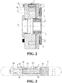
figure 2 shows an axial section of the braking assembly offigure 1 ; -
figure 3 shows detail III offigure 2 ; -
Figure 4 shows an isometric view of a sectioned braking assembly of a double armature plate electromagnetic brake in a variant of the first embodiment; -
figure 5 shows an axial section of the braking assembly offigure 4 ; -
figure 6 shows detail VI offigure 5 ; -
Figure 7 shows an isometric view of a sectioned braking assembly of a single armature plate electromagnetic brake according to a second embodiment; -
figure 8 shows an axial section of the braking assembly offigure 7 ; -
figure 9 shows detail IX offigure 8 ; -
Figure 10 shows an isometric view of a sectioned braking assembly of a double armature plate electromagnetic brake according to a variant of the second embodiment; -
figure 11 shows an axial section of the braking assembly offigure 10 ; -
figure 12 shows detail XII offigure 11 ; -
Figure 13 shows an isometric view of a braking assembly of a single armature plate electromagnetic brake according to a third embodiment; and -
figure 14 shows an isometric view of a braking assembly of a double armature plate electromagnetic brake according to a variant of the third embodiment. - Referring to the above figures, a
braking assembly 1 according to the present invention can be seen. - The brake according to the present invention comprises at least one
disc 6 configured to be fitted to a drive shaft defining a shaft axis X, preferably by means of ahub 5 but it is understood that thedisc 6 may also be fitted directly to the drive shaft or to any rotating part depending on the specific application. - The
disc 6 has a development according to a plane perpendicular to the shaft axis X and comprises two main opposite surfaces coated with amaterial 7 having a predetermined friction coefficient. This coating is characterised by a certain thickness, the extent of which varies according to the composition and the type of application for which the brake is used, which gradually decreases during use. - The brake according to the present invention further comprises an
electromagnet 8, for example of annular shape and coaxial withhub 5, and at least one movablearmature plate element 9 arranged betweendisc 6 andelectromagnet 8. It is to be understood thatelectromagnet 8 may have other shapes depending on the specific type of brake. Thearmature plate 9 is configured to be pushed againstdisc 6, when the power is off, by a plurality of compression springs (not shown) in a direction defined by the shaft axis X, and to be attracted to, and maintained in contact with,electromagnet 8 when the rotating organ on which the 6 is fitted is in operation. - An innovative aspect of the brake according to the present invention is that it further comprises a
sensor assembly 2 configured to measure the movement of thearmature plate 9 due to the attraction ofelectromagnet 8, as well as communication means, such as a wiring harness or a wireless transmission system, which transmit the measurements performed by thesensor assembly 2 to the outside of the brake. Thanks to this measurement, it is possible to evaluate the reduction in the thickness ofmaterial 7 based on the value of the air gap, i.e. the distance between thearmature plate 9 andelectromagnet 8 according to a direction parallel to the shaft axis X. - According to a first aspect of the invention, the
sensor assembly 2 comprises at least onestrain gauge 2a configured to undergo a deformation variation as a result of the movement of thearmature plate 9. The deformation variation of thestrain gauge 2a is then used to obtain a measurement of the distance that thearmature plate 9 travels to cross the air gap when it is attracted byelectromagnet 8. In the text of the description below, reference will be made to a single strain gauge, but it is always to be understood that it may refer to several strain gauges arranged together, as in the case of a "pair" or a "rosette" of strain gauges. - According to a further aspect, the
sensor assembly 2 is housed in ahousing 8a insideelectromagnet 8 extending in a direction parallel to the shaft axis X, starting from the surface ofelectromagnet 8 facing thearmature plate 9, and preferably in a position radially external to thecoil 8b ofelectromagnet 8.Said housing 8a is in communication with a threadedhole 8c of smaller diameter extending to the opposite surface ofelectromagnet 8, so as to accommodate a threadedadjuster 4 which is adjusted, preferably by means of anut 4a. The function ofadjuster 4 is to compensate for the inevitable manufacturing tolerances of the system so thatsensor 2 does not detect any wear whendisc 6 is new, i.e. that the reading ofthickness 7 is correct when the brake is applied for the first time. - According to still another aspect, the brake according to the present invention comprises a
single hub 5, asingle disc 6 and asingle armature plate 9, andhousing 8a is, in this case, the one described above. Or, alternatively, thebraking assembly 1 comprises twocoaxial hubs 5, which supportrespective discs 6, and twoarmature plates 9 each of which is disposed between arespective disc 6 andelectromagnet 8. In other words,electromagnet 8 is placed in the centre and sandwiched by thearmature plates 9 anddiscs 6, in that order and in a direction parallel to the shaft axis X (Figs.4-6 ). - The
electromagnet 8 preferably comprises twoexcitation coils 8b, each in correspondence with arespective armature plate 9 so that they can be attracted independently of each other. Thehousing 8a'housing sensor 2 is, in this case, a through hole extending between the two surfaces of theelectromagnet 8 facing the twoarmature plates 9, and the twoadjusters 4 are mounted on the latter in corresponding threadedholes 9a. - Referring to
figures 1-6 , thesensor assembly 2 of the electromagnetic brake according to a first embodiment comprises ahollow cylinder 2b whose axis is parallel to the shaft axis X, saidstrain gauge 2a being rigidly connected to an outer lateral surface of saidcylinder 2b. More particularly, thehollow cylinder 2b is made of a material characterised by a certain degree of elasticity, such as for example a metallic material, and thestrain gauge 2a is applied by means of gluing to the external lateral surface of thehollow cylinder 2b, which is configured to be inserted intohousing hollow cylinder 2b, preferably by means of its flanged ends which keep it coaxial tohousing - The
sensor assembly 2 also comprises asolid cylinder 2c, made of an elastically deformable material such as, for example, silicone, configured to be inserted substantially without play inside thehollow cylinder 2b with respect to which it is slightly shorter. Twoplugs solid cylinder 2c, i.e. one at each end, and are configured to penetrate inside thehollow cylinder 2b and axially compress thesolid cylinder 2c. - The
hollow cylinder 2b is advantageously configured to deform elastically, thereby deforming thestrain gauge 2a, due to the deformation of thesolid cylinder 2c compressed axially byplugs Figures 1-3 , in the case of a braking assembly with a single armature plate, plugs 2d, 2d' are arranged as follows: thefirst plug 2d is in contact with the surface of thearmature plate 9 facingelectromagnet 8, while thesecond plug 2d' is in contact withadjuster 4 insideelectromagnet 8. - When
electromagnet 8 is not activated, and thearmature plate 9 is pushed towardsdisc 6 by the compression springs, thehollow cylinder 2b is configured to undergo a first deformation. In other words, thesolid cylinder 2c is subjected to a certain degree of pre-compression so that even when the thickness ofmaterial 7 decreases, during the use of the brake, thefirst plug 2d is always in contact with the surface of thearmature plate 9 facingelectromagnet 8. On the other hand, whenelectromagnet 8 is activated, and thearmature plate 9 is attracted towards it, thehollow cylinder 2b is configured to undergo a second deformation, which is greater than the first deformation. - The change in deformation between the second deformation and the first deformation returns the measurement of the movement that the
armature plate 9 makes. The function ofadjuster 4, as mentioned above, is to compensate for the inevitable production tolerances of the system so that the degree of pre-compression to which thesolid cylinder 2c is subjected is adequate for the consumption of the entire thickness ofmaterial 7. - Referring to
figures 3-6 , in the case of a double armature plate braking assembly, plugs 2d, 2d' are configured as follows: thefirst plug 2d is in contact withadjuster 4 mounted on thefirst armature plate 9, and similarly thesecond plug 2d' is in contact withadjuster 4 mounted on thesecond armature plate 9. In this way, thesensor assembly 2 can advantageously obtain an independent measurement of the movement of each of the twoarmature plates 9 when the first armature plate and/or the second armature plate are attracted by theelectromagnet 8. Similarly to the singlearmature plate brake 9, whenelectromagnet 8 is not activated, thesolid cylinder 2c is configured to be subjected to a certain degree of pre-compression and the change in deformation of thehollow cylinder 2b between the second deformation and the first deformation returns a measurement of the movement that eacharmature plate 9 makes. - Referring to
figures 7-12 , thesensor assembly 2 of the electromagnetic brake according to a second embodiment comprises, in addition to thestrain gauge 2a, an elasticallydeformable strip 2e, preferably made of a metal material, to a surface of which thestrain gauge 2a is connected, preferably by gluing. Furthermore,strip 2e is configured to be elastically deformed as a result of the movement of thearmature plate 9, thereby deforming thestrain gauge 2a. - The
sensor assembly 2 comprises asupport structure 2f configured to be inserted intohousing strip 2e in such a way that both its ends protrude outwardly of saidsupport structure 2f and that saidstrip 2e can flex within the guide. Acentral protrusion 2g of thesupport structure 2f is configured to keep thestrip 2e flexed so that it forms an arc, preferably with convexity facing the shaft axis X. - Referring to
Figures 7-9 relating to a single armature plate braking assembly, similarly to the first embodiment, the first end ofstrip 2e is in contact with thearmature plate 9, while the second end is configured to be in contact withadjuster 4 withinelectromagnet 8. Similarly, referring tofigures 10-12 relating to a double armature plate braking assembly, the first and second ends ofstrip 2e are configured as follows: the first end ofstrip 2e is in contact withadjuster 4 mounted on thefirst armature plate 9, and similarly the second end is in contact withadjuster 4 mounted on thesecond armature plate 9. In this way, thesensor assembly 2 can advantageously obtain an independent measurement of the movement of each of the twoarmature plates 9 when the first armature plate and/or the second armature plate are attracted byelectromagnet 8. - Note that, thanks to
protrusion 2g, the bending ofstrip 2e occurs starting from an already arched position, so that thestrain gauge 2a always records the same type of movement, extension or compression, depending on the convex or concave surface ofstrip 2e to which it is applied. Furthermore, whenelectromagnet 8 is not activated,strip 2e is configured to have a certain degree of initial bending so that even when the thickness ofmaterial 7 decreases, during the use of the brake, the first end ofstrip 2e is always in contact with the surface of thearmature plate 9 facing electromagnet 8 (or both the first end and the second end ofstrip 2e, in the case of a double armature plate brake). - On the other hand, when
electromagnet 8 is activated, and thearmature plate 9 is attracted towards it,strip 2e is configured to undergo a second deformation, which is greater than the first deformation. The variation of deformation between the second deformation and the first deformation returns the measure of the distance that thearmature plate 9 travels to cross the air gap. - Referring to
figure 13 , an electromagnetic brake with a single armature plate, according to a third embodiment, provides for asensor group 2 in which thestrain gauge 2a is connected to aplate 2h, elastically deformable and preferably made of metallic material, arranged in a plane substantially perpendicular to the shaft axis X. Theplate 2h is constrained to the surface of thearmature plate 9 facingdisc 6 so as to be free to flex, thereby deforming thestrain gauge 2a accordingly. For example,plate 2h is fixed on the free perimeter portion of thearmature plate 9 by means offastenings 10 arranged at an end opposite to the portion where thestrain gauge 2a is connected. - A
peg 2i is bound toelectromagnet 8 and has a longitudinal development towards thearmature plate 9 according to a direction parallel to that of the shaft axis X. Thepeg 2i is advantageously configured to flexplate 2h according to a first deformation, whenelectromagnet 8 is not activated, and to flexplate 2h according to a second deformation, due to the movement of thearmature plate 9, by sliding along a through hole obtained in thearmature plate 9 in correspondence with the free portion ofplate 2h where thestrain gauge 2a is connected. - Similarly to the first and second embodiments, the deformation variation between the second deformation and the first deformation returns the measurement of the movement that the
armature plate 9 makes, but in this case thestrain gauge 2a must be arranged on the surface ofplate 2h facing thedisc 6, so as to avoid contact withpeg 2i, whereby it is used to detect a compression. Furthermore, the position ofpeg 2i is adjustable so that thesensor assembly 2 can be adjusted to compensate for manufacturing tolerances and the thickness ofmaterial 7 in order to obtain a correct reading of the initial thickness when the brake is first applied. - Finally, with reference to
figure 14 , in a variant of the third embodiment relating to a double armature plate brake, thesensor group 2 has substantially the same structure and arrangement as inFig. 13 , but in thiscase peg 2i is bound to thesecond armature 9 and passes through two aligned through holes obtained inelectromagnet 8 and in thefirst armature 9 in correspondence with the free portion ofplate 2h where thestrain gauge 2a is connected. - Thanks to the
sensor group 2 according to the present invention, it is possible to obtain an electromagnetic brake which allows to know the exact value of the consumption of the material with high friction coefficient in order to be able to program the maintenance interventions of the brake. Furthermore, the brake thus obtained is economical and simple to implement, while guaranteeing a measurement of the movement of the armature plate (or both armature plates) which is precise and robust to disturbances. - Possible variants or additions may be made by those skilled in the art to the embodiments described and illustrated herein while remaining within the scope of the following claims. In particular, although in the above description a strain gauge has always been indicated as the sensor means for detecting the deformation of the elastically deformable element (
cylinder 2b,strip 2e,plate 2h), it could be replaced by another technically equivalent sensor means having the necessary sensitivity, such as a magnetic (Reed, Hall), optoelectronic, resistive, piezoelectric, etc. sensor. - Further embodiments may also comprise the technical features of any of the following claims with the addition of one or more of the technical features described in the text or illustrated in the drawings, taken singly or in any combination thereof.
Claims (11)
- Electromagnetic brake including:- at least one disc (6) configured to be fitted, directly or by means of a hub (5), to a rotating element defining a shaft axis (X), said at least one disc (6) having opposite surfaces coated with a friction material (7),- an electromagnet (8),- at least one armature plate (9) placed between the disc (6) and said electromagnet (8) and movable in a direction defined by said shaft axis (X),- a plurality of compression springs arranged and configured to push said at least one armature plate (9) against the disc (6), according to said direction,- the armature plate (9) being configured to be attracted to the electromagnet (8), and kept in contact with it when the electromagnet (8) is operating,
characterized in that it further includes a sensor assembly (2) capable of measuring the movement along the shaft axis (X) direction, due to the attraction of the electromagnet (8), of said armature plate (9), said sensor assembly (2) comprising- an elastically deformable element (2b; 2e; 2h), placed on the brake so as to have an initial deformation when the electromagnet (8) is not activated and to undergo a change of deformation as a result of said attraction movement of the armature plate (9), and- sensor means configured to detect said change of deformation of said elastically deformable element (2b; 2e; 2h), as well as- means of communication transmitting outside the brake the measurements made by the sensor assembly (2). - Electromagnetic brake according to claim 1, characterized in that said sensor assembly (2) is housed in a housing (8a; 8a') extending inside the electromagnet (8) in a direction parallel to said shaft axis (X), starting from at least one first surface of the electromagnet (8) facing the armature plate (9).
- Electromagnetic brake according to claim 2, characterized in that said housing (8a; 8a') is located radially outside with respect to a coil (8b) of the electromagnet (8).
- Electromagnetic brake according to claim 2 or 3, characterized in that it includes only one disc (6) and one armature plate (9), and in that said housing (8a) is in communication with a threaded hole (8c) of smaller diameter extending to the opposite surface of the electromagnet (8) with respect to the surface from which the housing (8a) extends, a threaded adjuster (4) being housed in said threaded hole (8c) and extending to the housing (8a).
- Electromagnetic brake according to claim 2 or 3, characterized in that it includes two discs (6) and two armature plates (9), each of them being placed between a respective disc (6) and the electromagnet (8), said housing (8a') being a through hole extending between the two surfaces of the electromagnet (8) facing the two armature plates (9), each of which is provided with a threaded hole (9a) smaller in diameter than said housing (8a') and coaxial thereto, a threaded adjuster (4) being housed in each of said threaded holes (9a) and extending to the housing (8a').
- Electromagnetic brake according to any of the preceding claims, characterized in that the sensor means comprise at least one strain gauge (2a) rigidly connected to the elastic deformable element (2b; 2e; 2h).
- Electromagnetic brake according to claim 6 when dependent on one of claims 2-5, characterized in that the sensor assembly (2) includes:- an elastically deformable hollow cylinder (2b) configured to be inserted into the housing (8a; 8a'), the strain gauge (2a) being connected to an outer lateral surface of said hollow cylinder (2b);- an elastically deformable solid cylinder (2c) configured to be inserted substantially without play inside said hollow cylinder (2b) with respect to which it is slightly shorter;- two plugs (2d, 2d') inserted in correspondence of the bases of said solid cylinder (2c) and configured to penetrate inside the hollow cylinder (2b), and axially compress the solid cylinder (2c) ,
in which the hollow cylinder (2b) is inserted into the housing (8a, 8a') with adequate play to allow it to deform, said play being kept uniform over the entire circumference of the hollow cylinder (2b) preferably thanks to its flanged ends which keep it coaxial to the housing (8a, 8a'). - Electromagnetic brake according to claim 6 when dependent on one of claims 2-5, characterized in that the sensor assembly (2) includes:- an elastically deformable strip (2e), to one surface of which the strain gauge (2a) is connected;- a support structure (2f) configured to be inserted into the housing (8a, 8a') and comprising an internal guide having a longitudinal development and configured to accommodate said strip (2e) so that both ends thereof protrude outwards from said support structure (2f) and so that the strip (2e) can flex within said guide;- a central projection (2g) of the support structure (2f) configured to keep the strip (2e) flexed so that it forms an arc, preferably with convexity towards the shaft axis (X).
- Electromagnetic brake according to claim 6 when dependent on any of claims 1-4, characterized in that it includes only one disc (6) and one armature plate (9), and in that the sensor assembly (2) includes:- an elastically deformable plate (2h) to a surface of which the strain gauge (2a) is connected, said plate (2h) having a main development along a plane substantially perpendicular to the shaft axis (X) and being bound to the surface of the armature plate (9) facing the disc (6) so as to be free to flex;- a peg (2i) constrained to the electromagnet (8) in an adjustable manner and having a longitudinal development towards the armature plate (9) in a direction parallel to that of the shaft axis (X), said peg (2i) passing a through hole formed in the armature plate (9) at the free portion of the plate (2h) where the strain gauge (2a) is connected, and being configured to flex the plate (2h) according to a first deformation, when the electromagnet (8) is not activated, and to flex the plate (2h) according to a second deformation, greater than the first, due to the attraction movement of the armature plate (9).
- Electromagnetic brake according to claim 6 when depending on any of claims 1-3 or 5, characterized in that it includes two discs (6) and two armature plates (9), each of them being placed between a respective disc (6) and the electromagnet (8), and in that the sensor assembly (2) includes:- an elastically deformable plate (2h) to a surface of which the strain gauge (2a) is connected, said plate (2h) having a main development along a plane substantially perpendicular to the shaft axis (X) and being bound to the surface of a first armature plate (9) facing its respective disk (6) so as to be free to flex;- a peg (2i) constrained to the second armature plate (9) in an adjustable manner and having a longitudinal development towards said first armature plate (9) in a direction parallel to that of the shaft axis (X), said peg (2i) passing through aligned through holes formed in the electromagnet (8) and in the first armature plate (9) at the free portion of the plate (2h) where the strain gauge (2a) is connected, and being configured to flex the plate (2h) according to a first deformation, when the electromagnet (8) is not activated, and to flex the plate (2h) according to a second deformation, greater than the first, due to the attraction movement of the first and/or the second armature plate (9).
- Electromagnetic brake according to claim 9 or 10, characterized in that the plate (2h) is fixed on a free peripheral portion of the armature plate (9) by means of fastenings (10) placed at one end of the plate (2h) opposite the portion where the strain gauge (2a) is connected.
Applications Claiming Priority (1)
| Application Number | Priority Date | Filing Date | Title |
|---|---|---|---|
| IT102020000007642A IT202000007642A1 (en) | 2020-04-09 | 2020-04-09 | SYSTEM FOR MEASURING A DISPLACEMENT IN A BRAKING SYSTEM |
Publications (2)
| Publication Number | Publication Date |
|---|---|
| EP3892884A1 true EP3892884A1 (en) | 2021-10-13 |
| EP3892884B1 EP3892884B1 (en) | 2023-05-17 |
Family
ID=71895069
Family Applications (1)
| Application Number | Title | Priority Date | Filing Date |
|---|---|---|---|
| EP21167232.4A Active EP3892884B1 (en) | 2020-04-09 | 2021-04-07 | Electromagnetic brake |
Country Status (3)
| Country | Link |
|---|---|
| EP (1) | EP3892884B1 (en) |
| ES (1) | ES2946071T3 (en) |
| IT (1) | IT202000007642A1 (en) |
Cited By (1)
| Publication number | Priority date | Publication date | Assignee | Title |
|---|---|---|---|---|
| CN114838929A (en) * | 2022-05-13 | 2022-08-02 | 上海宇航系统工程研究所 | Electromagnetic brake testing arrangement of adjustable position appearance |
Citations (3)
| Publication number | Priority date | Publication date | Assignee | Title |
|---|---|---|---|---|
| DE19630779A1 (en) | 1996-07-31 | 1998-02-05 | Binder Magnete | Double linear solenoid actuator e.g. for locking device in motor vehicle automatic transmission selector lever device |
| US20020100646A1 (en) * | 2001-01-31 | 2002-08-01 | Maurice Kevin L. | Elevator brake assembly |
| DE102006009876B3 (en) * | 2006-03-03 | 2007-10-18 | Kendrion Binder Magnete Gmbh | Electromagnetically opening spring-loaded brake with a ventilation device and a microswitch |
-
2020
- 2020-04-09 IT IT102020000007642A patent/IT202000007642A1/en unknown
-
2021
- 2021-04-07 ES ES21167232T patent/ES2946071T3/en active Active
- 2021-04-07 EP EP21167232.4A patent/EP3892884B1/en active Active
Patent Citations (3)
| Publication number | Priority date | Publication date | Assignee | Title |
|---|---|---|---|---|
| DE19630779A1 (en) | 1996-07-31 | 1998-02-05 | Binder Magnete | Double linear solenoid actuator e.g. for locking device in motor vehicle automatic transmission selector lever device |
| US20020100646A1 (en) * | 2001-01-31 | 2002-08-01 | Maurice Kevin L. | Elevator brake assembly |
| DE102006009876B3 (en) * | 2006-03-03 | 2007-10-18 | Kendrion Binder Magnete Gmbh | Electromagnetically opening spring-loaded brake with a ventilation device and a microswitch |
Cited By (1)
| Publication number | Priority date | Publication date | Assignee | Title |
|---|---|---|---|---|
| CN114838929A (en) * | 2022-05-13 | 2022-08-02 | 上海宇航系统工程研究所 | Electromagnetic brake testing arrangement of adjustable position appearance |
Also Published As
| Publication number | Publication date |
|---|---|
| EP3892884B1 (en) | 2023-05-17 |
| IT202000007642A1 (en) | 2021-10-09 |
| ES2946071T3 (en) | 2023-07-12 |
Similar Documents
| Publication | Publication Date | Title |
|---|---|---|
| KR0136793B1 (en) | Automatic readjustment assembly for electromagnetic clutches and / or brakes | |
| JPS6052336B2 (en) | rotation transmission device | |
| CN107850157B (en) | Monitoring device for a disk brake of a motor vehicle | |
| EP2901036B1 (en) | Brake arrangement which can be actuated electromagnetically and electric motor | |
| EP3892884B1 (en) | Electromagnetic brake | |
| JP2011169385A (en) | Electromagnetic brake | |
| KR20040066129A (en) | Hoist for elevator | |
| US20080156594A1 (en) | Electromagnetic Brake Device | |
| DE102014000196B4 (en) | Brake arrangement, in particular having an electromagnetically actuated spring pressure brake | |
| US4362227A (en) | Clutches and brakes | |
| GB2116369A (en) | Electro-magnetic actuating deivce | |
| JP2008037611A (en) | Adjusting tool of brake device of elevator | |
| JPS6220922A (en) | Negative action electromagnetic brake | |
| US3586145A (en) | Electromagnetic clutch having stacked armature disks | |
| US11365773B2 (en) | Multi-disc brake for a vehicle drive, and a vehicle drive | |
| US7516826B2 (en) | Electro-slip clutch | |
| JP3065226B2 (en) | Electromagnetic coupling device | |
| JPS59739B2 (en) | Friction type electromagnetic coupling device | |
| JPH0353448Y2 (en) | ||
| CN220687899U (en) | Power-off brake | |
| JP7851660B1 (en) | braking device | |
| EP4502412A1 (en) | Brake with integrated motor position sensor | |
| JP2562031Y2 (en) | Non-excitation operated electromagnetic brake | |
| CN113700777A (en) | Brake | |
| JPH0861404A (en) | Negative-acting electromagnetic brake |
Legal Events
| Date | Code | Title | Description |
|---|---|---|---|
| PUAI | Public reference made under article 153(3) epc to a published international application that has entered the european phase |
Free format text: ORIGINAL CODE: 0009012 |
|
| STAA | Information on the status of an ep patent application or granted ep patent |
Free format text: STATUS: THE APPLICATION HAS BEEN PUBLISHED |
|
| AK | Designated contracting states |
Kind code of ref document: A1 Designated state(s): AL AT BE BG CH CY CZ DE DK EE ES FI FR GB GR HR HU IE IS IT LI LT LU LV MC MK MT NL NO PL PT RO RS SE SI SK SM TR |
|
| STAA | Information on the status of an ep patent application or granted ep patent |
Free format text: STATUS: REQUEST FOR EXAMINATION WAS MADE |
|
| 17P | Request for examination filed |
Effective date: 20220331 |
|
| RBV | Designated contracting states (corrected) |
Designated state(s): AL AT BE BG CH CY CZ DE DK EE ES FI FR GB GR HR HU IE IS IT LI LT LU LV MC MK MT NL NO PL PT RO RS SE SI SK SM TR |
|
| GRAP | Despatch of communication of intention to grant a patent |
Free format text: ORIGINAL CODE: EPIDOSNIGR1 |
|
| STAA | Information on the status of an ep patent application or granted ep patent |
Free format text: STATUS: GRANT OF PATENT IS INTENDED |
|
| INTG | Intention to grant announced |
Effective date: 20221201 |
|
| GRAS | Grant fee paid |
Free format text: ORIGINAL CODE: EPIDOSNIGR3 |
|
| GRAA | (expected) grant |
Free format text: ORIGINAL CODE: 0009210 |
|
| STAA | Information on the status of an ep patent application or granted ep patent |
Free format text: STATUS: THE PATENT HAS BEEN GRANTED |
|
| AK | Designated contracting states |
Kind code of ref document: B1 Designated state(s): AL AT BE BG CH CY CZ DE DK EE ES FI FR GB GR HR HU IE IS IT LI LT LU LV MC MK MT NL NO PL PT RO RS SE SI SK SM TR |
|
| REG | Reference to a national code |
Ref country code: GB Ref legal event code: FG4D |
|
| REG | Reference to a national code |
Ref country code: DE Ref legal event code: R096 Ref document number: 602021002379 Country of ref document: DE |
|
| REG | Reference to a national code |
Ref country code: CH Ref legal event code: EP |
|
| REG | Reference to a national code |
Ref country code: IE Ref legal event code: FG4D |
|
| REG | Reference to a national code |
Ref country code: AT Ref legal event code: REF Ref document number: 1568486 Country of ref document: AT Kind code of ref document: T Effective date: 20230615 |
|
| REG | Reference to a national code |
Ref country code: ES Ref legal event code: FG2A Ref document number: 2946071 Country of ref document: ES Kind code of ref document: T3 Effective date: 20230712 |
|
| REG | Reference to a national code |
Ref country code: LT Ref legal event code: MG9D |
|
| REG | Reference to a national code |
Ref country code: NL Ref legal event code: MP Effective date: 20230517 |
|
| REG | Reference to a national code |
Ref country code: AT Ref legal event code: MK05 Ref document number: 1568486 Country of ref document: AT Kind code of ref document: T Effective date: 20230517 |
|
| PG25 | Lapsed in a contracting state [announced via postgrant information from national office to epo] |
Ref country code: SE Free format text: LAPSE BECAUSE OF FAILURE TO SUBMIT A TRANSLATION OF THE DESCRIPTION OR TO PAY THE FEE WITHIN THE PRESCRIBED TIME-LIMIT Effective date: 20230517 Ref country code: PT Free format text: LAPSE BECAUSE OF FAILURE TO SUBMIT A TRANSLATION OF THE DESCRIPTION OR TO PAY THE FEE WITHIN THE PRESCRIBED TIME-LIMIT Effective date: 20230918 Ref country code: NO Free format text: LAPSE BECAUSE OF FAILURE TO SUBMIT A TRANSLATION OF THE DESCRIPTION OR TO PAY THE FEE WITHIN THE PRESCRIBED TIME-LIMIT Effective date: 20230817 Ref country code: NL Free format text: LAPSE BECAUSE OF FAILURE TO SUBMIT A TRANSLATION OF THE DESCRIPTION OR TO PAY THE FEE WITHIN THE PRESCRIBED TIME-LIMIT Effective date: 20230517 Ref country code: AT Free format text: LAPSE BECAUSE OF FAILURE TO SUBMIT A TRANSLATION OF THE DESCRIPTION OR TO PAY THE FEE WITHIN THE PRESCRIBED TIME-LIMIT Effective date: 20230517 |
|
| PG25 | Lapsed in a contracting state [announced via postgrant information from national office to epo] |
Ref country code: RS Free format text: LAPSE BECAUSE OF FAILURE TO SUBMIT A TRANSLATION OF THE DESCRIPTION OR TO PAY THE FEE WITHIN THE PRESCRIBED TIME-LIMIT Effective date: 20230517 Ref country code: PL Free format text: LAPSE BECAUSE OF FAILURE TO SUBMIT A TRANSLATION OF THE DESCRIPTION OR TO PAY THE FEE WITHIN THE PRESCRIBED TIME-LIMIT Effective date: 20230517 Ref country code: LV Free format text: LAPSE BECAUSE OF FAILURE TO SUBMIT A TRANSLATION OF THE DESCRIPTION OR TO PAY THE FEE WITHIN THE PRESCRIBED TIME-LIMIT Effective date: 20230517 Ref country code: LT Free format text: LAPSE BECAUSE OF FAILURE TO SUBMIT A TRANSLATION OF THE DESCRIPTION OR TO PAY THE FEE WITHIN THE PRESCRIBED TIME-LIMIT Effective date: 20230517 Ref country code: IS Free format text: LAPSE BECAUSE OF FAILURE TO SUBMIT A TRANSLATION OF THE DESCRIPTION OR TO PAY THE FEE WITHIN THE PRESCRIBED TIME-LIMIT Effective date: 20230917 Ref country code: HR Free format text: LAPSE BECAUSE OF FAILURE TO SUBMIT A TRANSLATION OF THE DESCRIPTION OR TO PAY THE FEE WITHIN THE PRESCRIBED TIME-LIMIT Effective date: 20230517 Ref country code: GR Free format text: LAPSE BECAUSE OF FAILURE TO SUBMIT A TRANSLATION OF THE DESCRIPTION OR TO PAY THE FEE WITHIN THE PRESCRIBED TIME-LIMIT Effective date: 20230818 |
|
| PG25 | Lapsed in a contracting state [announced via postgrant information from national office to epo] |
Ref country code: FI Free format text: LAPSE BECAUSE OF FAILURE TO SUBMIT A TRANSLATION OF THE DESCRIPTION OR TO PAY THE FEE WITHIN THE PRESCRIBED TIME-LIMIT Effective date: 20230517 |
|
| PG25 | Lapsed in a contracting state [announced via postgrant information from national office to epo] |
Ref country code: SK Free format text: LAPSE BECAUSE OF FAILURE TO SUBMIT A TRANSLATION OF THE DESCRIPTION OR TO PAY THE FEE WITHIN THE PRESCRIBED TIME-LIMIT Effective date: 20230517 |
|
| PG25 | Lapsed in a contracting state [announced via postgrant information from national office to epo] |
Ref country code: SM Free format text: LAPSE BECAUSE OF FAILURE TO SUBMIT A TRANSLATION OF THE DESCRIPTION OR TO PAY THE FEE WITHIN THE PRESCRIBED TIME-LIMIT Effective date: 20230517 Ref country code: SK Free format text: LAPSE BECAUSE OF FAILURE TO SUBMIT A TRANSLATION OF THE DESCRIPTION OR TO PAY THE FEE WITHIN THE PRESCRIBED TIME-LIMIT Effective date: 20230517 Ref country code: RO Free format text: LAPSE BECAUSE OF FAILURE TO SUBMIT A TRANSLATION OF THE DESCRIPTION OR TO PAY THE FEE WITHIN THE PRESCRIBED TIME-LIMIT Effective date: 20230517 Ref country code: EE Free format text: LAPSE BECAUSE OF FAILURE TO SUBMIT A TRANSLATION OF THE DESCRIPTION OR TO PAY THE FEE WITHIN THE PRESCRIBED TIME-LIMIT Effective date: 20230517 Ref country code: DK Free format text: LAPSE BECAUSE OF FAILURE TO SUBMIT A TRANSLATION OF THE DESCRIPTION OR TO PAY THE FEE WITHIN THE PRESCRIBED TIME-LIMIT Effective date: 20230517 Ref country code: CZ Free format text: LAPSE BECAUSE OF FAILURE TO SUBMIT A TRANSLATION OF THE DESCRIPTION OR TO PAY THE FEE WITHIN THE PRESCRIBED TIME-LIMIT Effective date: 20230517 |
|
| REG | Reference to a national code |
Ref country code: DE Ref legal event code: R097 Ref document number: 602021002379 Country of ref document: DE |
|
| PLBE | No opposition filed within time limit |
Free format text: ORIGINAL CODE: 0009261 |
|
| STAA | Information on the status of an ep patent application or granted ep patent |
Free format text: STATUS: NO OPPOSITION FILED WITHIN TIME LIMIT |
|
| 26N | No opposition filed |
Effective date: 20240220 |
|
| PG25 | Lapsed in a contracting state [announced via postgrant information from national office to epo] |
Ref country code: SI Free format text: LAPSE BECAUSE OF FAILURE TO SUBMIT A TRANSLATION OF THE DESCRIPTION OR TO PAY THE FEE WITHIN THE PRESCRIBED TIME-LIMIT Effective date: 20230517 |
|
| PG25 | Lapsed in a contracting state [announced via postgrant information from national office to epo] |
Ref country code: SI Free format text: LAPSE BECAUSE OF FAILURE TO SUBMIT A TRANSLATION OF THE DESCRIPTION OR TO PAY THE FEE WITHIN THE PRESCRIBED TIME-LIMIT Effective date: 20230517 |
|
| PG25 | Lapsed in a contracting state [announced via postgrant information from national office to epo] |
Ref country code: BG Free format text: LAPSE BECAUSE OF FAILURE TO SUBMIT A TRANSLATION OF THE DESCRIPTION OR TO PAY THE FEE WITHIN THE PRESCRIBED TIME-LIMIT Effective date: 20230517 |
|
| PG25 | Lapsed in a contracting state [announced via postgrant information from national office to epo] |
Ref country code: MC Free format text: LAPSE BECAUSE OF FAILURE TO SUBMIT A TRANSLATION OF THE DESCRIPTION OR TO PAY THE FEE WITHIN THE PRESCRIBED TIME-LIMIT Effective date: 20230517 |
|
| PG25 | Lapsed in a contracting state [announced via postgrant information from national office to epo] |
Ref country code: MC Free format text: LAPSE BECAUSE OF FAILURE TO SUBMIT A TRANSLATION OF THE DESCRIPTION OR TO PAY THE FEE WITHIN THE PRESCRIBED TIME-LIMIT Effective date: 20230517 Ref country code: BG Free format text: LAPSE BECAUSE OF FAILURE TO SUBMIT A TRANSLATION OF THE DESCRIPTION OR TO PAY THE FEE WITHIN THE PRESCRIBED TIME-LIMIT Effective date: 20230517 |
|
| REG | Reference to a national code |
Ref country code: CH Ref legal event code: PL |
|
| PG25 | Lapsed in a contracting state [announced via postgrant information from national office to epo] |
Ref country code: LU Free format text: LAPSE BECAUSE OF NON-PAYMENT OF DUE FEES Effective date: 20240407 |
|
| REG | Reference to a national code |
Ref country code: BE Ref legal event code: MM Effective date: 20240430 |
|
| PG25 | Lapsed in a contracting state [announced via postgrant information from national office to epo] |
Ref country code: LU Free format text: LAPSE BECAUSE OF NON-PAYMENT OF DUE FEES Effective date: 20240407 |
|
| PG25 | Lapsed in a contracting state [announced via postgrant information from national office to epo] |
Ref country code: BE Free format text: LAPSE BECAUSE OF NON-PAYMENT OF DUE FEES Effective date: 20240430 |
|
| PG25 | Lapsed in a contracting state [announced via postgrant information from national office to epo] |
Ref country code: BE Free format text: LAPSE BECAUSE OF NON-PAYMENT OF DUE FEES Effective date: 20240430 Ref country code: CH Free format text: LAPSE BECAUSE OF NON-PAYMENT OF DUE FEES Effective date: 20240430 |
|
| PG25 | Lapsed in a contracting state [announced via postgrant information from national office to epo] |
Ref country code: IE Free format text: LAPSE BECAUSE OF NON-PAYMENT OF DUE FEES Effective date: 20240407 |
|
| PGFP | Annual fee paid to national office [announced via postgrant information from national office to epo] |
Ref country code: DE Payment date: 20250422 Year of fee payment: 5 |
|
| PGFP | Annual fee paid to national office [announced via postgrant information from national office to epo] |
Ref country code: ES Payment date: 20250530 Year of fee payment: 5 |
|
| PGFP | Annual fee paid to national office [announced via postgrant information from national office to epo] |
Ref country code: IT Payment date: 20250402 Year of fee payment: 5 |
|
| PGFP | Annual fee paid to national office [announced via postgrant information from national office to epo] |
Ref country code: FR Payment date: 20250425 Year of fee payment: 5 |
|
| PG25 | Lapsed in a contracting state [announced via postgrant information from national office to epo] |
Ref country code: CY Free format text: LAPSE BECAUSE OF FAILURE TO SUBMIT A TRANSLATION OF THE DESCRIPTION OR TO PAY THE FEE WITHIN THE PRESCRIBED TIME-LIMIT; INVALID AB INITIO Effective date: 20210407 |
|
| PG25 | Lapsed in a contracting state [announced via postgrant information from national office to epo] |
Ref country code: HU Free format text: LAPSE BECAUSE OF FAILURE TO SUBMIT A TRANSLATION OF THE DESCRIPTION OR TO PAY THE FEE WITHIN THE PRESCRIBED TIME-LIMIT; INVALID AB INITIO Effective date: 20210407 |
|
| GBPC | Gb: european patent ceased through non-payment of renewal fee |
Effective date: 20250407 |
|
| PG25 | Lapsed in a contracting state [announced via postgrant information from national office to epo] |
Ref country code: GB Free format text: LAPSE BECAUSE OF NON-PAYMENT OF DUE FEES Effective date: 20250407 |