EP3892518A1 - Train speed limit control method and device - Google Patents
Train speed limit control method and device Download PDFInfo
- Publication number
- EP3892518A1 EP3892518A1 EP19892752.7A EP19892752A EP3892518A1 EP 3892518 A1 EP3892518 A1 EP 3892518A1 EP 19892752 A EP19892752 A EP 19892752A EP 3892518 A1 EP3892518 A1 EP 3892518A1
- Authority
- EP
- European Patent Office
- Prior art keywords
- train
- speed
- instability
- limit
- detected
- Prior art date
- Legal status (The legal status is an assumption and is not a legal conclusion. Google has not performed a legal analysis and makes no representation as to the accuracy of the status listed.)
- Granted
Links
Images


Classifications
-
- B—PERFORMING OPERATIONS; TRANSPORTING
- B61—RAILWAYS
- B61L—GUIDING RAILWAY TRAFFIC; ENSURING THE SAFETY OF RAILWAY TRAFFIC
- B61L23/00—Control, warning or like safety means along the route or between vehicles or trains
- B61L23/08—Control, warning or like safety means along the route or between vehicles or trains for controlling traffic in one direction only
- B61L23/14—Control, warning or like safety means along the route or between vehicles or trains for controlling traffic in one direction only automatically operated
-
- B—PERFORMING OPERATIONS; TRANSPORTING
- B61—RAILWAYS
- B61L—GUIDING RAILWAY TRAFFIC; ENSURING THE SAFETY OF RAILWAY TRAFFIC
- B61L15/00—Indicators provided on the vehicle or train for signalling purposes
- B61L15/0081—On-board diagnosis or maintenance
-
- B—PERFORMING OPERATIONS; TRANSPORTING
- B61—RAILWAYS
- B61L—GUIDING RAILWAY TRAFFIC; ENSURING THE SAFETY OF RAILWAY TRAFFIC
- B61L15/00—Indicators provided on the vehicle or train for signalling purposes
- B61L15/0058—On-board optimisation of vehicle or vehicle train operation
-
- B—PERFORMING OPERATIONS; TRANSPORTING
- B61—RAILWAYS
- B61L—GUIDING RAILWAY TRAFFIC; ENSURING THE SAFETY OF RAILWAY TRAFFIC
- B61L15/00—Indicators provided on the vehicle or train for signalling purposes
- B61L15/0062—On-board target speed calculation or supervision
-
- B—PERFORMING OPERATIONS; TRANSPORTING
- B61—RAILWAYS
- B61L—GUIDING RAILWAY TRAFFIC; ENSURING THE SAFETY OF RAILWAY TRAFFIC
- B61L25/00—Recording or indicating positions or identities of vehicles or trains or setting of track apparatus
- B61L25/02—Indicating or recording positions or identities of vehicles or trains
- B61L25/021—Measuring and recording of train speed
Definitions
- the present disclosure relates to the technical field of automatic train control, and in particular to a control method and a control device for limiting a speed of a train.
- instability of the train may occur.
- a instability warning should be provided timely, and the speed of the train should be limited timely to ensure the safe operation of the train.
- the instability of the train is managed by the driver imposing an appropriate speed limit according to experience, to ensure the safety of the train.
- the above process of limiting the speed of the train relies mainly on the experience of the driver, which requires the driver to always keep alert and operate carefully, and is also a tense work for the driver, which causes driving fatigue and easily affect the train driving safety due to the negligence of the driver.
- a control method and a control device for limiting a speed of a train are provided according to the present disclosure, to automatically control the speed of the train according to the instability of the train.
- a control method for limiting a speed of a train includes:
- the method further includes:
- the method further includes:
- the method further includes:
- the method further includes:
- a control device for limiting a speed of a train includes a first detection unit and a first speed limit unit.
- the first detection unit is configured to detect instability of the train when the train travels.
- the first speed limit unit is configured to apply a brake force to the train to impose a limit on a speed of the train, so as to cause the train to travel at a first speed, if instability of the train is detected by the first detection unit when the train travels.
- the device further includes a first determination unit and a speed limit releasing unit.
- the first determination unit is configured to determine whether instability of the train is detected again in a preset time period for which the train travels at the first speed since the limit is imposed on the speed of the train.
- the speed limit releasing unit is configured to release the limit on the speed of the train if instability of the train is not detected again.
- the device further includes a second determination unit and a second speed limit unit.
- the second determination unit is configured to determine whether instability of the train is detected within a preset distance that the train travels since the limit on the speed of the train is released.
- the second speed limit unit is configured to apply a brake force to the train to impose a limit on the speed of the train, so as to cause the train to travel at the first speed, if instability of the train is detected.
- the device further includes a third determination unit and a third speed limit unit.
- the third determination unit is configured to determine whether the number of times that instability of the train is detected when the train travels exceeds a preset number, within a preset distance that the train travels at the first speed since the limit is imposed on the speed of the train.
- the third speed limit unit is configured to limit the speed of the train to cause the train to travel at a second speed, if it is determined that the number of times that instability of the train is detected when the train travels exceeds the preset number, wherein the second speed is less than the first speed.
- the device further includes a fourth determination unit and a fifth speed limit unit.
- the fourth determination unit is configured to determine whether instability of the train is detected again when the train travels, in a case that the speed of the train is limited to cause the train to travel at the second speed.
- the fifth speed limit unit is configured to apply a brake force to the train until instability of the train is not detected if instability of the train is detected again when the train travels.
- instability of the train is automatically detected, and a brake force is automatically applied to the train to impose a limit on a speed of the train, so as to cause the train to travel at a first speed if instability of the train is detected, so as to automatically reduce the travelling speed of the train.
- the above solution applies to train operation, to reduce the labor intensity of the driver.
- the speed of the train is automatically and timely limited in a case that instability occurs during travelling of the train, thereby effectively avoiding negligence of the driver compromising train travelling safety.
- the embodiments of the present disclosure is applicable to an application scenario of limiting a speed of a train in a case that instability of the train occurs.
- a speed of a train is limited according to instability of the train.
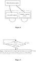
- Figure 1 is a schematic structural diagram of a system for controlling travelling of a train according to an embodiment of the present disclosure.
- a network control system of a train shown in Figure 1 is responsible for the centralized control of respective modules of the train, including a power system, a water supply system, a power supply system, and the like, of the train.
- the embodiments of the present disclosure focus on the above network control system controlling the power system of the train, including controlling the power system to perform braking, to control the speed of the train, and the like.
- the power system shown in Figure 1 is mainly used for providing power to the train, performing braking, and providing power to the train according to a given speed such that the train travels at a certain speed, according to a control signal from the train network control system.
- the instability warning apparatus in Figure 1 is configured to detect instability of the train, and send an instability signal to the network control system of the train if instability of the train is detected, to inform the network control system of the train that the instability occurs.
- the above instability includes lateral instability, longitudinal instability and undulating instability, and the like.
- the lateral instability is taken as an example to describe a control method for warning in a case that lateral instability of a train is detected, and limiting the speed of the train according to the lateral instability.
- the technical solution according to the embodiments of the present disclosure is applied to the network control system shown in Figure 1 .
- the network control system sends the control signal to the power system of the train according to the instability warning signal outputted by the instability warning apparatus, to limit the speed of the train.
- the technical solution according to the embodiment of the present disclosure is applicable to a hardware control processing device in the network control system, such as a central controller, a processor, and the like, or may alternatively exist as a control program in the network control system for implementing speed limitation of a train when executed, or as a control function module in a large control system to implement the speed limitation of the train.
- the present disclosure does not strictly limit the specific form of the execution subject of the technical solution according to the embodiment of the present disclosure.
- any software program or hardware device that capable of performing the technical solution according to the embodiment of the present disclosure is theoretically applicable to implement the technical solution according to the embodiments of the present disclosure, to implement the automatic speed limit of the train.
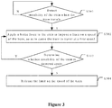
- a control method for limiting a speed of a train is provided according to an embodiment of the present disclosure. Referring to Figure 2 , the method includes the following steps S201 to S203.
- step S201 instability of the train is detected when the train travels.
- the instability warning apparatus of the train monitors whether lateral instability of the train occurs in a real-time manner, and sends an instability warning signal to the network control system if the lateral instability of the train occurs.
- the network control system determines that instability of the train is detected when the train travels.
- the instability warning apparatus monitors whether lateral instability of the train occurs in a real-time manner, and timely outputs the instability warning signal to the network control system if the lateral instability of the train is detected. Therefore, the network control system detects the instability of the train when the train travels by directly detecting whether the instability warning signal sent by the instability warning apparatus is received. If the instability warning signal sent by the instability warning apparatus is received, it may be determined that instability of the train is detected when the train travels. If the instability warning signal sent by the instability warning apparatus is not received, it may be determined that instability of the train is not detected when the train travels.
- the above network control system periodically detects instability of the train when train the travels. That is, the network control system detects whether the instability warning signal sent by the instability warning apparatus is received at a certain time period.
- the detection period may be set small enough to increase the detection frequency.
- the detection process may be a continuous detection process if the detection period is set small enough.
- instability is not detected, the detection is continued. If instability is detected, the subsequent speed limit operation is performed, and detection of instability is continued in a case that the speed limit operation is performed.
- step S202 is performed to apply a brake force to the train to impose a limit on a speed of the train, so as to cause the train to travel at a first speed.
- the network control system on reception of the instability warning signal sent by the instability warning apparatus, that is, when determining that instability of the train is detected, the network control system sends a brake instruction to the power system of the train, to control the power system to apply a brake force to the train, so as to reduce the speed of the train.
- the network control system further sends a speed limit instruction to the power system of the train when sending the brake instruction to the power system.
- the speed limit instruction is used to instruct to limit the traveling speed of the train to a specified speed.
- the network control system sends the speed limit instruction to the power system of the train to impose a limit on a speed of the train, so as to cause the train to travel at the first speed, where the first speed is less than the travelling speed at which instability of the train occurs, so as to reduce the travelling speed of the train.
- the power system of train On reception of the above brake instruction and the above speed limit instruction, the power system of train applies an appropriate brake force to the train based the travelling speed specified in the speed limit instruction, to reduce the traveling speed of the train to the travelling speed specified in the speed limit instruction, and to cause the train to maintain the travelling speed.
- the first speed may be set according to train design, actual route conditions and train operation experiences. For example, instability of a high-speed train traveling at a speed of 350km/h may be eliminated when the speed is reduced to 280km/h according to the train test experience. In this case, the first speed is set to 280km/h.
- the network controller automatically sends an instruction to the power system of the train to apply a brake force to the train, to impose a limit on a speed of the train, so as to cause the train to travel at the first speed, that is, to limit the speed of the train, so as to cause the train to travel at the first speed 280km/h, so that instability of the train may be eliminated.
- the above brake instruction and the above speed limit instruction may be included in one control instruction, that is sent to the power system of the train.
- one control instruction is used for instructing to apply a brake force to the train and to limit the travelling speed of the train to a certain speed.
- the above brake instruction and the above speed limit instruction may be sent to the power system successively or simultaneously as two separate instructions.
- instability of the train is automatically detected, and a brake force is automatically applied to the train to impose a limit on a speed of the train, so as to cause the train to travel at a first speed if instability of the train is detected, so as to automatically reduce the travelling speed of the train.
- the above solution applies to train operation, to reduce the labor intensity of the driver.
- the speed of the train is automatically and timely limited in a case that instability occurs during travelling of the train, thereby effectively avoiding negligence of the driver compromising train travelling safety.
- the above control method for limiting a speed of a train further includes the following step S303.
- step S303 it is determined whether instability of the train is detected again in a preset time period for which the train travels at the first speed since the limit is imposed on the speed of the train.
- the network control system determines whether instability of the train is detected again, that is, the network control system determines whether the instability warning signal sent by the instability warning apparatus is received again in the preset time period for which the train travels at the first speed since the limit is imposed on the speed of the train.
- the instability warning signal sent by the instability warning apparatus is received again, that is, instability of the train is detected again, it is determined that the train is still in the state of instability. In this case, the speed of the train is continuously limited such that the train travels at the first speed.
- step S304 is performed to release the limit on the speed of the train.
- the instability warning signal sent by the instability warning apparatus is not received again, that is, if instability of the train is not detected again in the preset time period for which the train travels at the first speed since the limit is imposed on the speed of the train, it is determined that the train travels stably or the train is pulled into a smooth rail section.
- the limit imposed on the speed of the train is released in this case, and the train gradually speeds up, that is, the travelling speed is increased.
- the network control system limits the speed of the train to 280km/h.
- the limit on the speed of the train is released if the network control system does not receive the instability warning signal sent by the instability warning apparatus again, and the train gradually speeds up until the speed reaches 350km/h. If the network control system receives the instability warning signal sent by the instability warning apparatus again in the two minutes, it is determined that instability of the train still occurs, the limit on the speed of the train is maintained such that the train travels at the speed of 280km/h.
- Steps S301 and S302 in this embodiment of the present disclosure respectively correspond to steps S201 and S202 in the method embodiment shown in Figure 2 . Reference may be made to the method embodiment shown in Figure 2 for contents of steps S301 and S302, which will not be repeated here.
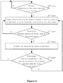
- the above control method for limiting a speed of a train further includes the following step S405.
- step S405 it is determined whether instability of the train is detected within a preset distance that the train travels since the limit on the speed of the train is released.
- the network control system determines whether instability of the train is detected, that is, whether the instability warning signal sent by the instability warning apparatus is received, in the predetermined distance that the train travels at a gradually increased speed.
- the train may travel at a speed higher than the first speed, and the procedure returns to detecting instability of the train when the train travels.
- step S402 is performed to apply a brake force to the train, to impose a limit on the speed of the train, so as to cause the train to travel at the first speed.
- the network control system applies a brake force to the train again to impose a limit on the speed of the train, so as to cause the train to travel at the first speed.
- the network control system brake the train again to limit the speed of the train to 280km/h.
- Steps S401 and S404 in this embodiment of the present disclosure respectively correspond to steps S301 and S304 in the method embodiment shown in Figure 3 . Reference may be made to the method embodiment shown in Figure 3 for the contents of steps S401 to S404, which will not be repeated here.
- control method for limiting a speed of a train further includes the following steps S503 to S506.
- step S503 it is determined whether the number of times that instability of the train is detected when the train travels exceeds a preset number, within a preset distance that the train travels at the first speed since the limit is imposed on the speed of the train.
- the network control system continues detecting instability of the train, that is, detecting whether the instability warning signal sent by the instability warning apparatus is received again.
- the speed of the train is maintained at the first speed.
- step S504 is performed to limit the speed of the train to cause the train to travel at a second speed, where the second speed is less than the first speed.
- the network control system sends the brake command to the power system of the train to further brake the train, so as to limit the speed of the train to the second speed that is less than the first speed, so that safe traveling of the train is ensured.
- the network control system receives the instability warning signal sent by the instability warning apparatus for two times, that is, the network control system detects instability of the train for two times within the distance of 300km that the train travels. It is indicated that the instability of the train is not eliminated when the train travels at the limited speed of 280km/h. In this case, the network control system further limits the speed of the train.
- the network control system sends the brake instruction to the power system of the train, to cause the power system of the train to apply a brake force to the train, so as to limit the speed of the train to 200km/h.
- the network control system continues detecting instability of the train when the train travels, and continues to perform step S505, to determine whether instability of the train is detected again when the train travels.
- the network control system continues detecting instability of the train occurs when the train travels, that is, the network control system detects whether the instability warning signal sent by the instability warning apparatus is received again.
- step S506 is performed to apply a brake force to the train until instability of the train is not detected.
- the network control system detects instability of the train again, that is, the network control system receives the instability warning signal sent by the instability warning apparatus again, the network control system sends the brake instruction to the power system of the train again, to instruct the power system to apply a brake force to the train, so as to reduce the speed until instability of the train does not occur.
- the instability of the train not occurring indicates that instability of the train does not occur in a case that the brake force is applied to the train such that the speed of the train is further reduced, the train travels at the reduced speed for a preset time period or a preset distance.
- the network control system applies a brake force to the train again to further reduce the speed until instability of the train does not occur.
- Steps S501 and S502 in this embodiment of the present disclosure respectively correspond to steps S201 and S202 in the method embodiment shown in Figure 2 . Reference may be made to the method embodiment shown in Figure 2 for the contents of steps S501 and 502, which will not be repeated here.
- a control device for limiting a speed of a train is further provided according to another embodiment of the present disclosure.
- the device includes a first detection unit 100 and a first speed limit unit 110.
- the first detection unit 100 is configured to detect instability of the train when the train travels.
- the first speed limit unit 110 is configured to apply a brake force to the train to impose a limit on a speed of the train, so as to cause the train to travel at a first speed, if instability of the train is detected by the first detection unit 100 when the train travels.
- the device further includes a first determination unit 120 and a speed limit releasing unit 130, as shown in Figure 7 .
- the first determination unit 120 is configured to determine whether instability of the train is detected again in a preset time period for which the train travels at the first speed since the limit is imposed on the speed of the train.
- the speed limit releasing unit 130 is configured to release the limit on the speed of the train if instability of the train is not detected again.
- the device further includes a second determination unit 140 and a second speed limit unit 150, as shown in Figure 8 .
- the second determination unit 140 is configured to determine whether instability of the train is detected within a preset distance that the train travels since the limit on the speed of the train is released.
- the second speed limit unit 150 is configured to apply a brake force to the train to impose a limit on the speed of the train, so as to cause the train to travel at the first speed, if instability of the train is detected.
- the device further includes a third determination unit 160 and a third speed limit unit 170, as shown in Figure 9 .
- the third determination unit 160 is configured to determine whether the number of times that instability of the train is detected when the train travels exceeds a preset number, within a preset distance that the train travels at the first speed since the limit is imposed on the speed of the train.
- the third speed limit unit 170 is configured to limit the speed of the train to cause the train to travel at a second speed, if it is determined that the number of times that instability of the train is detected when the train travels exceeds the preset number, where the second speed is less than the first speed.
- the device further includes a fourth determination unit and a fifth speed limit unit.
- the fourth determination unit is configured to determine whether instability of the train is detected again when the train travels, in a case that the speed of the train is limited to cause the train to travel at the second speed.
- the fifth speed limit unit is configured to apply a brake force to the train until instability of the train is not detected if instability of the train is detected again when the train travels.
- the method or algorithm steps described in embodiments of the present disclosure may be implemented directly with hardware, software units executed by processors, or a combination of the hardware and the software units.
- the software units may be stored in random access memory (RAM), memory, read-only memory (ROM), electrically programmable ROM, electrically erasable programmable ROM, register, hard disk, removable disk, CD-ROM, or any other form of storage medium well known in the technical field.
Landscapes
- Engineering & Computer Science (AREA)
- Mechanical Engineering (AREA)
- Health & Medical Sciences (AREA)
- Biomedical Technology (AREA)
- General Health & Medical Sciences (AREA)
- Electric Propulsion And Braking For Vehicles (AREA)
- Train Traffic Observation, Control, And Security (AREA)
Abstract
Description
- The present application claims priority to
Chinese Patent Application No. 201811480041.X - The present disclosure relates to the technical field of automatic train control, and in particular to a control method and a control device for limiting a speed of a train.
- With the continuous development of high-speed train industry in China, the number of high-speed trains continuously grows, while the speed of high-speed trains continuously increases. Stable and safe operation of trains are the key factors that ensure the normal operation of high-speed train system.
- Since the route condition and the weather change frequently during travelling of a train, which affects the operation of the train, instability of the train may occur. When instability of a train occurs, a instability warning should be provided timely, and the speed of the train should be limited timely to ensure the safe operation of the train. Currently, the instability of the train is managed by the driver imposing an appropriate speed limit according to experience, to ensure the safety of the train. The above process of limiting the speed of the train relies mainly on the experience of the driver, which requires the driver to always keep alert and operate carefully, and is also a tense work for the driver, which causes driving fatigue and easily affect the train driving safety due to the negligence of the driver.
- To address the above deficiencies in conventional technology, a control method and a control device for limiting a speed of a train are provided according to the present disclosure, to automatically control the speed of the train according to the instability of the train.
- A control method for limiting a speed of a train is provided. The method includes:
- detecting instability of the train when the train travels; and
- applying a brake force to the train to impose a limit on a speed of the train, so as to cause the train to travel at a first speed, if instability of the train is detected when the train travels.
- Optionally, the method further includes:
- determining whether instability of the train is detected again in a preset time period for which the train travels at the first speed since the limit is imposed on the speed of the train; and
- releasing the limit on the speed of the train if instability of the train is not detected again.
- Optionally, the method further includes:
- determining whether instability of the train is detected within a preset distance that the train travels since the limit on the speed of the train is released; and
- applying a brake force to the train to impose a limit on the speed of the train, so as to cause the train to travel at the first speed, if instability of the train is detected.
- Optionally, the method further includes:
- determining whether the number of times that instability of the train is detected when the train travels exceeds a preset number, within a preset distance that the train travels at the first speed since the limit is imposed on the speed of the train; and
- limiting the speed of the train to cause the train to travel at a second speed, if it is determined that the number of times that instability of the train is detected when the train travels exceeds the preset number, wherein the second speed is less than the first speed.
- Optionally, in a case that the speed of the train is limited to cause the train to travel at the second speed, the method further includes:
- determining whether instability of the train is detected again when the train travels;
- applying a brake force to the train until instability of the train is not detected if instability of the train is detected again when the train travels.
- A control device for limiting a speed of a train is provided. The device includes a first detection unit and a first speed limit unit.
- The first detection unit is configured to detect instability of the train when the train travels.
- The first speed limit unit is configured to apply a brake force to the train to impose a limit on a speed of the train, so as to cause the train to travel at a first speed, if instability of the train is detected by the first detection unit when the train travels.
- Optionally, the device further includes a first determination unit and a speed limit releasing unit.
- The first determination unit is configured to determine whether instability of the train is detected again in a preset time period for which the train travels at the first speed since the limit is imposed on the speed of the train.
- The speed limit releasing unit is configured to release the limit on the speed of the train if instability of the train is not detected again.
- Optionally, the device further includes a second determination unit and a second speed limit unit.
- The second determination unit is configured to determine whether instability of the train is detected within a preset distance that the train travels since the limit on the speed of the train is released.
- The second speed limit unit is configured to apply a brake force to the train to impose a limit on the speed of the train, so as to cause the train to travel at the first speed, if instability of the train is detected.
- Optionally, the device further includes a third determination unit and a third speed limit unit.
- The third determination unit is configured to determine whether the number of times that instability of the train is detected when the train travels exceeds a preset number, within a preset distance that the train travels at the first speed since the limit is imposed on the speed of the train.
- The third speed limit unit is configured to limit the speed of the train to cause the train to travel at a second speed, if it is determined that the number of times that instability of the train is detected when the train travels exceeds the preset number, wherein the second speed is less than the first speed.
- Optionally, the device further includes a fourth determination unit and a fifth speed limit unit.
- The fourth determination unit is configured to determine whether instability of the train is detected again when the train travels, in a case that the speed of the train is limited to cause the train to travel at the second speed.
- The fifth speed limit unit is configured to apply a brake force to the train until instability of the train is not detected if instability of the train is detected again when the train travels.
- With the control method for limiting a speed of a train according to the present disclosure, instability of the train is automatically detected, and a brake force is automatically applied to the train to impose a limit on a speed of the train, so as to cause the train to travel at a first speed if instability of the train is detected, so as to automatically reduce the travelling speed of the train. The above solution applies to train operation, to reduce the labor intensity of the driver. The speed of the train is automatically and timely limited in a case that instability occurs during travelling of the train, thereby effectively avoiding negligence of the driver compromising train travelling safety.
- The drawings to be used in the description of the embodiments or the conventional technology will be described briefly as follows, so that the technical solutions according to the embodiments of the present disclosure or according to the conventional technology will become clearer. It is apparent that the drawings in the following description only illustrate some embodiments of the present disclosure. For those skilled in the art, other drawings may be obtained according to these drawings without any creative work.
-
Figure 1 is a schematic structural diagram of a system for controlling travelling of a train according to an embodiment of the present disclosure; -
Figure 2 is a flow chart of a control method for limiting a speed of a train according to an embodiment of the present disclosure; -
Figure 3 is a flow chart of a control method for limiting a speed of a train according to another embodiment of the present disclosure; -
Figure 4 is a flow chart of a control method for limiting a speed of a train according to another embodiment of the present disclosure; -
Figure 5 is a flow chart of a control method for limiting a speed of a train according to another embodiment of the present disclosure; -
Figure 6 is a schematic structural diagram of a control device for limiting a speed of a train according to an embodiment of the present disclosure; -
Figure 7 is a schematic structural diagram of a control device for limiting a speed of a train according to another embodiment of the present disclosure; -
Figure 8 is a schematic structural diagram of a control device for limiting a speed of a train according to another embodiment of the present disclosure; and -
Figure 9 is a schematic structural diagram of a control device for limiting a speed of a train according to another embodiment of the present disclosure. - The embodiments of the present disclosure is applicable to an application scenario of limiting a speed of a train in a case that instability of the train occurs. With the technical solutions according to the embodiments of the present disclosure, a speed of a train is limited according to instability of the train.
-
Figure 1 is a schematic structural diagram of a system for controlling travelling of a train according to an embodiment of the present disclosure. A network control system of a train shown inFigure 1 is responsible for the centralized control of respective modules of the train, including a power system, a water supply system, a power supply system, and the like, of the train. The embodiments of the present disclosure focus on the above network control system controlling the power system of the train, including controlling the power system to perform braking, to control the speed of the train, and the like. - The power system shown in
Figure 1 is mainly used for providing power to the train, performing braking, and providing power to the train according to a given speed such that the train travels at a certain speed, according to a control signal from the train network control system. - The instability warning apparatus in
Figure 1 is configured to detect instability of the train, and send an instability signal to the network control system of the train if instability of the train is detected, to inform the network control system of the train that the instability occurs. The above instability includes lateral instability, longitudinal instability and undulating instability, and the like. In the embodiments of the present disclosure, the lateral instability is taken as an example to describe a control method for warning in a case that lateral instability of a train is detected, and limiting the speed of the train according to the lateral instability. - The technical solution according to the embodiments of the present disclosure is applied to the network control system shown in
Figure 1 . With the technical solution according to the embodiment of the present disclosure, the network control system sends the control signal to the power system of the train according to the instability warning signal outputted by the instability warning apparatus, to limit the speed of the train. - The technical solution according to the embodiment of the present disclosure is applicable to a hardware control processing device in the network control system, such as a central controller, a processor, and the like, or may alternatively exist as a control program in the network control system for implementing speed limitation of a train when executed, or as a control function module in a large control system to implement the speed limitation of the train. The present disclosure does not strictly limit the specific form of the execution subject of the technical solution according to the embodiment of the present disclosure. In theory, any software program or hardware device that capable of performing the technical solution according to the embodiment of the present disclosure is theoretically applicable to implement the technical solution according to the embodiments of the present disclosure, to implement the automatic speed limit of the train.
- Technical solutions according to embodiments of the present disclosure are described clearly and completely hereinafter in conjunction with drawings used in the embodiments of the present disclosure. Apparently, the described embodiments are only some embodiments of the present disclosure rather than all the embodiments. Any other embodiments obtained by those skilled in the art based on the embodiments of the present disclosure without any creative work fall in the scope of protection of the present disclosure.
- A control method for limiting a speed of a train is provided according to an embodiment of the present disclosure. Referring to
Figure 2 , the method includes the following steps S201 to S203. - In step S201, instability of the train is detected when the train travels.
- Referring to
Figure 1 , the instability warning apparatus of the train monitors whether lateral instability of the train occurs in a real-time manner, and sends an instability warning signal to the network control system if the lateral instability of the train occurs. In this case, the network control system determines that instability of the train is detected when the train travels. - It should be noted that, since the instability warning apparatus monitors whether lateral instability of the train occurs in a real-time manner, and timely outputs the instability warning signal to the network control system if the lateral instability of the train is detected. Therefore, the network control system detects the instability of the train when the train travels by directly detecting whether the instability warning signal sent by the instability warning apparatus is received. If the instability warning signal sent by the instability warning apparatus is received, it may be determined that instability of the train is detected when the train travels. If the instability warning signal sent by the instability warning apparatus is not received, it may be determined that instability of the train is not detected when the train travels.
- The above network control system periodically detects instability of the train when train the travels. That is, the network control system detects whether the instability warning signal sent by the instability warning apparatus is received at a certain time period. In order to ensure timely detection of the instability, the detection period may be set small enough to increase the detection frequency. Alternatively, the detection process may be a continuous detection process if the detection period is set small enough.
- If instability is not detected, the detection is continued. If instability is detected, the subsequent speed limit operation is performed, and detection of instability is continued in a case that the speed limit operation is performed.
- If instability of the train is detected when the train travels, step S202 is performed to apply a brake force to the train to impose a limit on a speed of the train, so as to cause the train to travel at a first speed.
- Specifically, on reception of the instability warning signal sent by the instability warning apparatus, that is, when determining that instability of the train is detected, the network control system sends a brake instruction to the power system of the train, to control the power system to apply a brake force to the train, so as to reduce the speed of the train.
- Furthermore, the network control system further sends a speed limit instruction to the power system of the train when sending the brake instruction to the power system. The speed limit instruction is used to instruct to limit the traveling speed of the train to a specified speed. In an embodiment of the present disclosure, the network control system sends the speed limit instruction to the power system of the train to impose a limit on a speed of the train, so as to cause the train to travel at the first speed, where the first speed is less than the travelling speed at which instability of the train occurs, so as to reduce the travelling speed of the train.
- On reception of the above brake instruction and the above speed limit instruction, the power system of train applies an appropriate brake force to the train based the travelling speed specified in the speed limit instruction, to reduce the traveling speed of the train to the travelling speed specified in the speed limit instruction, and to cause the train to maintain the travelling speed.
- It should be noted that, the first speed may be set according to train design, actual route conditions and train operation experiences. For example, instability of a high-speed train traveling at a speed of 350km/h may be eliminated when the speed is reduced to 280km/h according to the train test experience. In this case, the first speed is set to 280km/h. Based on the above setting, according to the technical solution of an embodiment of the present disclosure, if instability of a train occurs when the train travels at the speed of 350km/h, the network controller automatically sends an instruction to the power system of the train to apply a brake force to the train, to impose a limit on a speed of the train, so as to cause the train to travel at the first speed, that is, to limit the speed of the train, so as to cause the train to travel at the first speed 280km/h, so that instability of the train may be eliminated.
- In an exemplary embodiment, the above brake instruction and the above speed limit instruction may be included in one control instruction, that is sent to the power system of the train. For example, one control instruction is used for instructing to apply a brake force to the train and to limit the travelling speed of the train to a certain speed. Alternatively, the above brake instruction and the above speed limit instruction may be sent to the power system successively or simultaneously as two separate instructions.
- As can be seen from the above description, with the control method for limiting a speed of a train according to the present disclosure, instability of the train is automatically detected, and a brake force is automatically applied to the train to impose a limit on a speed of the train, so as to cause the train to travel at a first speed if instability of the train is detected, so as to automatically reduce the travelling speed of the train. The above solution applies to train operation, to reduce the labor intensity of the driver. The speed of the train is automatically and timely limited in a case that instability occurs during travelling of the train, thereby effectively avoiding negligence of the driver compromising train travelling safety.
- Referring to
Figure 3 , in another embodiment of the present disclosure, the above control method for limiting a speed of a train further includes the following step S303. - In step S303, it is determined whether instability of the train is detected again in a preset time period for which the train travels at the first speed since the limit is imposed on the speed of the train.
- In the preset time period for which the train travels at the first speed since the limit is imposed on the speed of the train, the network control system determines whether instability of the train is detected again, that is, the network control system determines whether the instability warning signal sent by the instability warning apparatus is received again in the preset time period for which the train travels at the first speed since the limit is imposed on the speed of the train.
- If the instability warning signal sent by the instability warning apparatus is received again, that is, instability of the train is detected again, it is determined that the train is still in the state of instability. In this case, the speed of the train is continuously limited such that the train travels at the first speed.
- If instability of the train is not detected again, step S304 is performed to release the limit on the speed of the train.
- Specifically, if the instability warning signal sent by the instability warning apparatus is not received again, that is, if instability of the train is not detected again in the preset time period for which the train travels at the first speed since the limit is imposed on the speed of the train, it is determined that the train travels stably or the train is pulled into a smooth rail section. In an embodiment of the present disclosure, the limit imposed on the speed of the train is released in this case, and the train gradually speeds up, that is, the travelling speed is increased.
- For example, in a case that instability of the train occurs when the train travels at the speed of 350km/h, according to the technical solution of embodiment of the present disclosure, the network control system limits the speed of the train to 280km/h. In two minutes for which the train travels at the speed of 280km/h since the speed of the train is limited to 280km/h, the limit on the speed of the train is released if the network control system does not receive the instability warning signal sent by the instability warning apparatus again, and the train gradually speeds up until the speed reaches 350km/h. If the network control system receives the instability warning signal sent by the instability warning apparatus again in the two minutes, it is determined that instability of the train still occurs, the limit on the speed of the train is maintained such that the train travels at the speed of 280km/h.
- Steps S301 and S302 in this embodiment of the present disclosure respectively correspond to steps S201 and S202 in the method embodiment shown in
Figure 2 . Reference may be made to the method embodiment shown inFigure 2 for contents of steps S301 and S302, which will not be repeated here. - Referring to
Figure 4 , according to another embodiment of the present disclosure, the above control method for limiting a speed of a train further includes the following step S405. - In step S405, it is determined whether instability of the train is detected within a preset distance that the train travels since the limit on the speed of the train is released.
- Specifically, in a case that the speed of the train is limited, when it is determined that the train is pulled out of an unstable rail section and the limit on the speed of the train is released, the network control system determines whether instability of the train is detected, that is, whether the instability warning signal sent by the instability warning apparatus is received, in the predetermined distance that the train travels at a gradually increased speed.
- If instability of the train is not detected within the above distance, the train may travel at a speed higher than the first speed, and the procedure returns to detecting instability of the train when the train travels.
- If instability of the train is detected, step S402 is performed to apply a brake force to the train, to impose a limit on the speed of the train, so as to cause the train to travel at the first speed.
- Specifically, if instability of the train is detected within the preset distance that the train travels since the limit on the speed of the train is released, it indicates that instability of the train occurs again after the previous occurrence of instability. In this case, the network control system applies a brake force to the train again to impose a limit on the speed of the train, so as to cause the train to travel at the first speed.
- For example, within two minutes for which the train travels at the speed of 280km/h since the speed of 350km/h of the train is limited to 280km/h, if instability of the train does not occur again, the limit on the speed of the train is released, and the train gradually speeds up. Within 300km in which the train speeds up and travels since the limit on the speed of the train is released, if instability of the train does not occur, the train travels at a maximum allowable speed. If it is detected that instability of the train occurs within the above 300km, the network control system brake the train again to limit the speed of the train to 280km/h.
- Steps S401 and S404 in this embodiment of the present disclosure respectively correspond to steps S301 and S304 in the method embodiment shown in
Figure 3 . Reference may be made to the method embodiment shown inFigure 3 for the contents of steps S401 to S404, which will not be repeated here. - Optionally, referring to
Figure 5 , in another embodiment of the present disclosure, the control method for limiting a speed of a train further includes the following steps S503 to S506. - In step S503, it is determined whether the number of times that instability of the train is detected when the train travels exceeds a preset number, within a preset distance that the train travels at the first speed since the limit is imposed on the speed of the train.
- Specifically, if instability occurs when the train travels, the speed of the train is limited to the first speed according to the technical solution of embodiment of the present disclosure, and the train travels at the first speed for the preset distance, the network control system continues detecting instability of the train, that is, detecting whether the instability warning signal sent by the instability warning apparatus is received again.
- Within the preset distance that the train travels at the first speed, if instability of the train is not detected, or instability is detected but the number of times that instability is detected does not exceeds a preset number, the speed of the train is maintained at the first speed.
- If the number of times that instability of the train is detected when the train travels exceeds a preset number, step S504 is performed to limit the speed of the train to cause the train to travel at a second speed, where the second speed is less than the first speed.
- Specifically, in the preset distance in which the train travels at the first speed, if the number of times that instability of the train is detected exceeds the preset number, the network control system sends the brake command to the power system of the train to further brake the train, so as to limit the speed of the train to the second speed that is less than the first speed, so that safe traveling of the train is ensured.
- For example, since the speed of 350km/h of the train at which instability occurs is limited to 280km/h, within a distance of 300km in which the train travels at 280km/h, the network control system receives the instability warning signal sent by the instability warning apparatus for two times, that is, the network control system detects instability of the train for two times within the distance of 300km that the train travels. It is indicated that the instability of the train is not eliminated when the train travels at the limited speed of 280km/h. In this case, the network control system further limits the speed of the train. The network control system sends the brake instruction to the power system of the train, to cause the power system of the train to apply a brake force to the train, so as to limit the speed of the train to 200km/h.
- Furthermore, in a case that the speed of the train is limited to the second speed according to above technical solution, the network control system continues detecting instability of the train when the train travels, and continues to perform step S505, to determine whether instability of the train is detected again when the train travels.
- Specifically, in a case that the network control system limits the speed of the train to the second speed, the network control system continues detecting instability of the train occurs when the train travels, that is, the network control system detects whether the instability warning signal sent by the instability warning apparatus is received again.
- If instability of the train is not detected again when the train travels, the speed of the train is maintained at the second speed.
- If instability of the train is detected again, step S506 is performed to apply a brake force to the train until instability of the train is not detected.
- Specifically, in a case that the speed of the train is limited to the second speed, when the train travels at the second speed, the network control system detects instability of the train again, that is, the network control system receives the instability warning signal sent by the instability warning apparatus again, the network control system sends the brake instruction to the power system of the train again, to instruct the power system to apply a brake force to the train, so as to reduce the speed until instability of the train does not occur.
- It should be noted that, the instability of the train not occurring indicates that instability of the train does not occur in a case that the brake force is applied to the train such that the speed of the train is further reduced, the train travels at the reduced speed for a preset time period or a preset distance.
- If the brake force is applied to the train to further reduce the speed of the train, and instability of the train occurs again when the train travels at the reduced speed within the preset time period or the preset distance, the network control system applies a brake force to the train again to further reduce the speed until instability of the train does not occur.
- Steps S501 and S502 in this embodiment of the present disclosure respectively correspond to steps S201 and S202 in the method embodiment shown in
Figure 2 . Reference may be made to the method embodiment shown inFigure 2 for the contents of steps S501 and 502, which will not be repeated here. - A control device for limiting a speed of a train is further provided according to another embodiment of the present disclosure. Referring to
Figure 6 , the device includes afirst detection unit 100 and a firstspeed limit unit 110. - The
first detection unit 100 is configured to detect instability of the train when the train travels. - The first
speed limit unit 110 is configured to apply a brake force to the train to impose a limit on a speed of the train, so as to cause the train to travel at a first speed, if instability of the train is detected by thefirst detection unit 100 when the train travels. - Optionally, in another embodiment of the present disclosure, the device further includes a
first determination unit 120 and a speedlimit releasing unit 130, as shown inFigure 7 . - The
first determination unit 120 is configured to determine whether instability of the train is detected again in a preset time period for which the train travels at the first speed since the limit is imposed on the speed of the train. - The speed
limit releasing unit 130 is configured to release the limit on the speed of the train if instability of the train is not detected again. - Optionally, in another embodiment of the present disclosure, the device further includes a
second determination unit 140 and a secondspeed limit unit 150, as shown inFigure 8 . - The
second determination unit 140 is configured to determine whether instability of the train is detected within a preset distance that the train travels since the limit on the speed of the train is released. - The second
speed limit unit 150 is configured to apply a brake force to the train to impose a limit on the speed of the train, so as to cause the train to travel at the first speed, if instability of the train is detected. - Optionally, in another embodiment of the present disclosure, the device further includes a
third determination unit 160 and a thirdspeed limit unit 170, as shown inFigure 9 . - The
third determination unit 160 is configured to determine whether the number of times that instability of the train is detected when the train travels exceeds a preset number, within a preset distance that the train travels at the first speed since the limit is imposed on the speed of the train. - The third
speed limit unit 170 is configured to limit the speed of the train to cause the train to travel at a second speed, if it is determined that the number of times that instability of the train is detected when the train travels exceeds the preset number, where the second speed is less than the first speed. - Optionally, in another embodiment of the present disclosure, the device further includes a fourth determination unit and a fifth speed limit unit.
- The fourth determination unit is configured to determine whether instability of the train is detected again when the train travels, in a case that the speed of the train is limited to cause the train to travel at the second speed.
- The fifth speed limit unit is configured to apply a brake force to the train until instability of the train is not detected if instability of the train is detected again when the train travels.
- Specifically, one can refer to the content of the above method embodiment for the operations of respective units of the control device for limiting a speed of a train, which will not repeat here.
- It should be noted that, in the present specification, the embodiments are described in progressive manner. Each embodiment mainly focuses on an aspect different from other embodiments, and reference can be made to these similar parts among the embodiments. The device disclosed in the embodiment corresponds to the method disclosed in the embodiment, and is described relatively simply. For detailed description of the device, reference may be made to the related description of the method
- It may be known by those skilled in the art that, units and steps in each method described in conjunction with the embodiments disclosed herein can be realized by electronic hardware, computer software or a combination thereof. In order to clearly illustrate interchangeability of the hardware and the software, steps and composition of each embodiment have been described generally in view of functions in the above specification. Whether the function is executed in a hardware way or in a software way depends on application of the technical solution and design constraint condition. Those skilled in the art can use different method for each application to realize the described function, and this is not considered to be beyond the scope of the application.
- The method or algorithm steps described in embodiments of the present disclosure may be implemented directly with hardware, software units executed by processors, or a combination of the hardware and the software units. The software units may be stored in random access memory (RAM), memory, read-only memory (ROM), electrically programmable ROM, electrically erasable programmable ROM, register, hard disk, removable disk, CD-ROM, or any other form of storage medium well known in the technical field.
- Finally, it should be further noted that the relationship terminologies such as "first", "second" and the like are only used herein to distinguish one entity or operation from another, rather than to necessitate or imply that the actual relationship or order exists between the entities or operations. Furthermore, terms of "include", "comprise" or any other variants are intended to be non-exclusive. Therefore, a process, method, article or device including a plurality of elements includes not only the elements but also other elements that are not enumerated, or also include the elements inherent for the process, method, article or device. Unless expressively limited otherwise, the statement "comprising (including) one..." does not exclude the case that other similar elements may exist in the process, method, article or device.
- The above illustration of the disclosed embodiments enables those skilled in the art to implement or practice the present disclosure. Many changes to these embodiments are apparent for those skilled in the art, and general principles defined herein can be implemented in other embodiments without departing the spirit or scope of the present disclosure. Hence, the present disclosure is not limited to the embodiments disclosed herein, but is to conform to the widest scope consistent with principles and novel features disclosed herein.
Claims (10)
- A control method for limiting a speed of a train, comprising:detecting instability of the train when the train travels; andapplying a brake force to the train to impose a limit on a speed of the train, so as to cause the train to travel at a first speed, if instability of the train is detected when the train travels.
- The method according to claim 1, further comprising:determining whether instability of the train is detected again in a preset time period for which the train travels at the first speed since the limit is imposed on the speed of the train; andreleasing the limit on the speed of the train if instability of the train is not detected again.
- The method according to claim 2, further comprising:determining whether instability of the train is detected within a preset distance that the train travels since the limit on the speed of the train is released; andapplying a brake force to the train to impose a limit on the speed of the train, so as to cause the train to travel at the first speed, if instability of the train is detected.
- The method according to claim 1 or 3, further comprising:determining whether the number of times that instability of the train is detected when the train travels exceeds a preset number, within a preset distance that the train travels at the first speed since the limit is imposed on the speed of the train; andlimiting the speed of the train to cause the train to travel at a second speed, if it is determined that the number of times that instability of the train is detected when the train travels exceeds the preset number, wherein the second speed is less than the first speed.
- The method according to claim 4, wherein in a case that the speed of the train is limited to cause the train to travel at the second speed, the method further comprises:determining whether instability of the train is detected again when the train travels;applying a brake force to the train until instability of the train is not detected if instability of the train is detected again when the train travels.
- A control device for limiting a speed of a train, comprising:a first detection unit configured to detect instability of the train when the train travels; anda first speed limit unit configured to apply a brake force to the train to impose a limit on a speed of the train, so as to cause the train to travel at a first speed, if instability of the train is detected by the first detection unit when the train travels.
- The device according to claim 6, further comprising:a first determination unit configured to determine whether instability of the train is detected again in a preset time period for which the train travels at the first speed since the limit is imposed on the speed of the train; anda speed limit releasing unit configured to release the limit on the speed of the train if instability of the train is not detected again.
- The device according to claim 7, further comprising:a second determination unit configured to determine whether instability of the train is detected within a preset distance that the train travels since the limit on the speed of the train is released; anda second speed limit unit configured to apply a brake force to the train to impose a limit on the speed of the train, so as to cause the train to travel at the first speed, if instability of the train is detected.
- The device according to claim 6 or 8, further comprising:a third determination unit configured to determine whether the number of times that instability of the train is detected when the train travels exceeds a preset number, within a preset distance that the train travels at the first speed since the limit is imposed on the speed of the train; anda third speed limit unit configured to limit the speed of the train to cause the train to travel at a second speed, if it is determined that the number of times that instability of the train is detected when the train travels exceeds the preset number, wherein the second speed is less than the first speed.
- The apparatus according to claim 9, further comprising:a fourth determination unit configured to determine whether instability of the train is detected again when the train travels, in a case that the limit is imposed on the speed of the train to cause the train to travel at the second speed;a fifth speed limit unit configured to apply a brake force to the train until instability of the train is not detected if instability of the train is detected again when the train travels.
Applications Claiming Priority (2)
| Application Number | Priority Date | Filing Date | Title |
|---|---|---|---|
| CN201811480041.XA CN110539782A (en) | 2018-12-05 | 2018-12-05 | train speed limit control method and device |
| PCT/CN2019/117092 WO2020114204A1 (en) | 2018-12-05 | 2019-11-11 | Train speed limit control method and device |
Publications (4)
| Publication Number | Publication Date |
|---|---|
| EP3892518A1 true EP3892518A1 (en) | 2021-10-13 |
| EP3892518A4 EP3892518A4 (en) | 2022-08-24 |
| EP3892518C0 EP3892518C0 (en) | 2025-01-08 |
| EP3892518B1 EP3892518B1 (en) | 2025-01-08 |
Family
ID=68701903
Family Applications (1)
| Application Number | Title | Priority Date | Filing Date |
|---|---|---|---|
| EP19892752.7A Active EP3892518B1 (en) | 2018-12-05 | 2019-11-11 | Train speed limit control method and device |
Country Status (5)
| Country | Link |
|---|---|
| EP (1) | EP3892518B1 (en) |
| CN (1) | CN110539782A (en) |
| MY (1) | MY207339A (en) |
| SG (1) | SG11202008190YA (en) |
| WO (1) | WO2020114204A1 (en) |
Families Citing this family (2)
| Publication number | Priority date | Publication date | Assignee | Title |
|---|---|---|---|---|
| CN113320570B (en) * | 2021-06-01 | 2022-07-26 | 中车唐山机车车辆有限公司 | Bogie instability control method and device, train and storage medium |
| CN114506306B (en) * | 2022-01-10 | 2023-01-20 | 北京全路通信信号研究设计院集团有限公司 | Train downhill air braking adjusting method and system |
Family Cites Families (8)
| Publication number | Priority date | Publication date | Assignee | Title |
|---|---|---|---|---|
| KR970069708A (en) * | 1996-04-16 | 1997-11-07 | 김영귀 | Detection of drive part abnormality and automatic brake system |
| CN102874280B (en) * | 2012-09-20 | 2015-06-24 | 南车南京浦镇车辆有限公司 | Train speed limitation control method based on train network system |
| CN104071111B (en) * | 2014-07-15 | 2016-06-08 | 吉林大学 | The full extension anti-unstability Real-Time Monitoring of automobile train and early warning system |
| DE102014213863A1 (en) * | 2014-07-16 | 2016-01-21 | Siemens Aktiengesellschaft | Method for stabilizing a rail vehicle |
| CN105083251B (en) * | 2014-11-28 | 2017-12-01 | 中车青岛四方机车车辆股份有限公司 | Automatic braking of train control circuit based on bogie unstability detection means |
| CN204355033U (en) * | 2014-11-28 | 2015-05-27 | 南车青岛四方机车车辆股份有限公司 | Based on the automatic braking of train control circuit of bogie truck unstability detecting device |
| CN104890684B (en) * | 2015-06-25 | 2017-05-17 | 长春轨道客车股份有限公司 | Automatic train speed restricting and speed restriction removing method based on TCMS (train control and management system) |
| CN105818820B (en) * | 2016-03-23 | 2018-06-29 | 株洲中车时代电气股份有限公司 | A kind of train bogie unstability automatic control system and control method |
-
2018
- 2018-12-05 CN CN201811480041.XA patent/CN110539782A/en active Pending
-
2019
- 2019-11-11 MY MYPI2020004364A patent/MY207339A/en unknown
- 2019-11-11 WO PCT/CN2019/117092 patent/WO2020114204A1/en not_active Ceased
- 2019-11-11 EP EP19892752.7A patent/EP3892518B1/en active Active
- 2019-11-11 SG SG11202008190YA patent/SG11202008190YA/en unknown
Also Published As
| Publication number | Publication date |
|---|---|
| MY207339A (en) | 2025-02-19 |
| EP3892518C0 (en) | 2025-01-08 |
| EP3892518B1 (en) | 2025-01-08 |
| EP3892518A4 (en) | 2022-08-24 |
| SG11202008190YA (en) | 2020-09-29 |
| CN110539782A (en) | 2019-12-06 |
| WO2020114204A1 (en) | 2020-06-11 |
Similar Documents
| Publication | Publication Date | Title |
|---|---|---|
| EP4227146A1 (en) | Vehicle torque control method and device, vehicle, and storage medium | |
| EP3892518B1 (en) | Train speed limit control method and device | |
| EP2816435B1 (en) | Methods and apparatus of notification of a flight asymmetry influencing an aircraft | |
| US20210016798A1 (en) | Method and apparatus for detecting and avoiding collision applied to vehicle | |
| WO2024103705A1 (en) | Train control method and apparatus, and medium | |
| CN111169509B (en) | Temporary speed limit control method and device | |
| CN110814051B (en) | Deviation rectification control method | |
| DE102013203775B4 (en) | Method for controlling an automatic emergency braking system | |
| CN106427975A (en) | Failure processing method for rail-train wired electronic-control air braking system | |
| CN113635917A (en) | A vehicle automatic driving control method and device | |
| TW201737215A (en) | Exception monitoring and alarming method and device | |
| CN103253539A (en) | Control method capable of preventing strip steel of galvanizing unit from deflection and belt braking in operation | |
| DE102014215128A1 (en) | Assumption of responsibility for highly automated driving | |
| WO2025065845A1 (en) | Method and system for controlling chase shearing of strip-steel transverse cutting line | |
| WO2019135310A1 (en) | Operation assistance system | |
| KR20170073013A (en) | Method and system for control of impulse for soft landing of ladle | |
| WO2018225344A1 (en) | In-vehicle control device and train control system | |
| CN105015576B (en) | A kind of control method and device of the checking cylinder of brake | |
| KR101851971B1 (en) | Tarin automatic driving control appatatus and method | |
| CN106326042A (en) | Method and device for determining operating state | |
| CN110650881B (en) | Train safety guarantee system, train safety guarantee control method and train device | |
| CN105128881B (en) | Bogie lock shaft fault monitoring method, apparatus and system | |
| JP2019036261A (en) | Stack overflow detection device and vehicle control system | |
| CN116946220A (en) | A manual assisted driving method and device | |
| CN112849223A (en) | Cruise mode control method and system and railway vehicle |
Legal Events
| Date | Code | Title | Description |
|---|---|---|---|
| STAA | Information on the status of an ep patent application or granted ep patent |
Free format text: STATUS: THE INTERNATIONAL PUBLICATION HAS BEEN MADE |
|
| PUAI | Public reference made under article 153(3) epc to a published international application that has entered the european phase |
Free format text: ORIGINAL CODE: 0009012 |
|
| STAA | Information on the status of an ep patent application or granted ep patent |
Free format text: STATUS: REQUEST FOR EXAMINATION WAS MADE |
|
| 17P | Request for examination filed |
Effective date: 20200825 |
|
| AK | Designated contracting states |
Kind code of ref document: A1 Designated state(s): AL AT BE BG CH CY CZ DE DK EE ES FI FR GB GR HR HU IE IS IT LI LT LU LV MC MK MT NL NO PL PT RO RS SE SI SK SM TR |
|
| DAV | Request for validation of the european patent (deleted) | ||
| DAX | Request for extension of the european patent (deleted) | ||
| REG | Reference to a national code |
Ref country code: DE Ref legal event code: R079 Free format text: PREVIOUS MAIN CLASS: B61L0023140000 Ipc: B61L0015000000 Ref document number: 602019064751 Country of ref document: DE |
|
| A4 | Supplementary search report drawn up and despatched |
Effective date: 20220726 |
|
| RIC1 | Information provided on ipc code assigned before grant |
Ipc: B61L 3/00 20060101ALI20220720BHEP Ipc: B61L 15/00 20060101AFI20220720BHEP |
|
| GRAP | Despatch of communication of intention to grant a patent |
Free format text: ORIGINAL CODE: EPIDOSNIGR1 |
|
| STAA | Information on the status of an ep patent application or granted ep patent |
Free format text: STATUS: GRANT OF PATENT IS INTENDED |
|
| INTG | Intention to grant announced |
Effective date: 20240723 |
|
| GRAS | Grant fee paid |
Free format text: ORIGINAL CODE: EPIDOSNIGR3 |
|
| GRAA | (expected) grant |
Free format text: ORIGINAL CODE: 0009210 |
|
| STAA | Information on the status of an ep patent application or granted ep patent |
Free format text: STATUS: THE PATENT HAS BEEN GRANTED |
|
| AK | Designated contracting states |
Kind code of ref document: B1 Designated state(s): AL AT BE BG CH CY CZ DE DK EE ES FI FR GB GR HR HU IE IS IT LI LT LU LV MC MK MT NL NO PL PT RO RS SE SI SK SM TR |
|
| REG | Reference to a national code |
Ref country code: GB Ref legal event code: FG4D |
|
| REG | Reference to a national code |
Ref country code: CH Ref legal event code: EP |
|
| REG | Reference to a national code |
Ref country code: DE Ref legal event code: R096 Ref document number: 602019064751 Country of ref document: DE |
|
| REG | Reference to a national code |
Ref country code: IE Ref legal event code: FG4D |
|
| U01 | Request for unitary effect filed |
Effective date: 20250207 |
|
| U07 | Unitary effect registered |
Designated state(s): AT BE BG DE DK EE FI FR IT LT LU LV MT NL PT RO SE SI Effective date: 20250213 |
|
| PG25 | Lapsed in a contracting state [announced via postgrant information from national office to epo] |
Ref country code: RS Free format text: LAPSE BECAUSE OF FAILURE TO SUBMIT A TRANSLATION OF THE DESCRIPTION OR TO PAY THE FEE WITHIN THE PRESCRIBED TIME-LIMIT Effective date: 20250408 |
|
| PG25 | Lapsed in a contracting state [announced via postgrant information from national office to epo] |
Ref country code: PL Free format text: LAPSE BECAUSE OF FAILURE TO SUBMIT A TRANSLATION OF THE DESCRIPTION OR TO PAY THE FEE WITHIN THE PRESCRIBED TIME-LIMIT Effective date: 20250108 |
|
| PG25 | Lapsed in a contracting state [announced via postgrant information from national office to epo] |
Ref country code: ES Free format text: LAPSE BECAUSE OF FAILURE TO SUBMIT A TRANSLATION OF THE DESCRIPTION OR TO PAY THE FEE WITHIN THE PRESCRIBED TIME-LIMIT Effective date: 20250108 |
|
| PG25 | Lapsed in a contracting state [announced via postgrant information from national office to epo] |
Ref country code: IS Free format text: LAPSE BECAUSE OF FAILURE TO SUBMIT A TRANSLATION OF THE DESCRIPTION OR TO PAY THE FEE WITHIN THE PRESCRIBED TIME-LIMIT Effective date: 20250508 Ref country code: NO Free format text: LAPSE BECAUSE OF FAILURE TO SUBMIT A TRANSLATION OF THE DESCRIPTION OR TO PAY THE FEE WITHIN THE PRESCRIBED TIME-LIMIT Effective date: 20250408 |
|
| PG25 | Lapsed in a contracting state [announced via postgrant information from national office to epo] |
Ref country code: HR Free format text: LAPSE BECAUSE OF FAILURE TO SUBMIT A TRANSLATION OF THE DESCRIPTION OR TO PAY THE FEE WITHIN THE PRESCRIBED TIME-LIMIT Effective date: 20250108 |
|
| PG25 | Lapsed in a contracting state [announced via postgrant information from national office to epo] |
Ref country code: GR Free format text: LAPSE BECAUSE OF FAILURE TO SUBMIT A TRANSLATION OF THE DESCRIPTION OR TO PAY THE FEE WITHIN THE PRESCRIBED TIME-LIMIT Effective date: 20250409 |
|
| PG25 | Lapsed in a contracting state [announced via postgrant information from national office to epo] |
Ref country code: SM Free format text: LAPSE BECAUSE OF FAILURE TO SUBMIT A TRANSLATION OF THE DESCRIPTION OR TO PAY THE FEE WITHIN THE PRESCRIBED TIME-LIMIT Effective date: 20250108 |
|
| PG25 | Lapsed in a contracting state [announced via postgrant information from national office to epo] |
Ref country code: CZ Free format text: LAPSE BECAUSE OF FAILURE TO SUBMIT A TRANSLATION OF THE DESCRIPTION OR TO PAY THE FEE WITHIN THE PRESCRIBED TIME-LIMIT Effective date: 20250108 |
|
| PG25 | Lapsed in a contracting state [announced via postgrant information from national office to epo] |
Ref country code: SK Free format text: LAPSE BECAUSE OF FAILURE TO SUBMIT A TRANSLATION OF THE DESCRIPTION OR TO PAY THE FEE WITHIN THE PRESCRIBED TIME-LIMIT Effective date: 20250108 |
|
| PLBE | No opposition filed within time limit |
Free format text: ORIGINAL CODE: 0009261 |
|
| STAA | Information on the status of an ep patent application or granted ep patent |
Free format text: STATUS: NO OPPOSITION FILED WITHIN TIME LIMIT |
|
| 26N | No opposition filed |
Effective date: 20251009 |
|
| U20 | Renewal fee for the european patent with unitary effect paid |
Year of fee payment: 7 Effective date: 20251125 |