EP3892481A1 - Vehicle door structure - Google Patents
Vehicle door structure Download PDFInfo
- Publication number
- EP3892481A1 EP3892481A1 EP20741374.1A EP20741374A EP3892481A1 EP 3892481 A1 EP3892481 A1 EP 3892481A1 EP 20741374 A EP20741374 A EP 20741374A EP 3892481 A1 EP3892481 A1 EP 3892481A1
- Authority
- EP
- European Patent Office
- Prior art keywords
- panel
- outer panel
- damping materials
- door
- hem
- Prior art date
- Legal status (The legal status is an assumption and is not a legal conclusion. Google has not performed a legal analysis and makes no representation as to the accuracy of the status listed.)
- Granted
Links
Images



Classifications
-
- B—PERFORMING OPERATIONS; TRANSPORTING
- B60—VEHICLES IN GENERAL
- B60J—WINDOWS, WINDSCREENS, NON-FIXED ROOFS, DOORS, OR SIMILAR DEVICES FOR VEHICLES; REMOVABLE EXTERNAL PROTECTIVE COVERINGS SPECIALLY ADAPTED FOR VEHICLES
- B60J10/00—Sealing arrangements
- B60J10/50—Sealing arrangements characterised by means for prevention or reduction of noise, e.g. of rattling or vibration of windows
-
- B—PERFORMING OPERATIONS; TRANSPORTING
- B60—VEHICLES IN GENERAL
- B60J—WINDOWS, WINDSCREENS, NON-FIXED ROOFS, DOORS, OR SIMILAR DEVICES FOR VEHICLES; REMOVABLE EXTERNAL PROTECTIVE COVERINGS SPECIALLY ADAPTED FOR VEHICLES
- B60J5/00—Doors
- B60J5/04—Doors arranged at the vehicle sides
- B60J5/042—Reinforcement elements
- B60J5/0422—Elongated type elements, e.g. beams, cables, belts or wires
- B60J5/0423—Elongated type elements, e.g. beams, cables, belts or wires characterised by position in the lower door structure
- B60J5/0426—Elongated type elements, e.g. beams, cables, belts or wires characterised by position in the lower door structure the elements being arranged at the beltline
-
- B—PERFORMING OPERATIONS; TRANSPORTING
- B60—VEHICLES IN GENERAL
- B60J—WINDOWS, WINDSCREENS, NON-FIXED ROOFS, DOORS, OR SIMILAR DEVICES FOR VEHICLES; REMOVABLE EXTERNAL PROTECTIVE COVERINGS SPECIALLY ADAPTED FOR VEHICLES
- B60J5/00—Doors
- B60J5/04—Doors arranged at the vehicle sides
- B60J5/042—Reinforcement elements
- B60J5/0422—Elongated type elements, e.g. beams, cables, belts or wires
- B60J5/0423—Elongated type elements, e.g. beams, cables, belts or wires characterised by position in the lower door structure
- B60J5/0429—Elongated type elements, e.g. beams, cables, belts or wires characterised by position in the lower door structure the elements being arranged diagonally
-
- B—PERFORMING OPERATIONS; TRANSPORTING
- B60—VEHICLES IN GENERAL
- B60J—WINDOWS, WINDSCREENS, NON-FIXED ROOFS, DOORS, OR SIMILAR DEVICES FOR VEHICLES; REMOVABLE EXTERNAL PROTECTIVE COVERINGS SPECIALLY ADAPTED FOR VEHICLES
- B60J5/00—Doors
- B60J5/04—Doors arranged at the vehicle sides
- B60J5/048—Doors arranged at the vehicle sides characterised by the material
Definitions
- the present invention relates to a door structure of a vehicle including: an outer panel; an inner member arranged on an inner side of the outer panel in a vehicle width direction; and a rigid member arranged between the inner member and the outer panel.
- an excitation force caused by, for example, an engine sound, a tire sound, or a wind sound transmitted to a door via an air acts on an outer panel of the door from an outer side in a vehicle width direction.
- the outer panel of the door is typically a thin plate.
- the excitation force may cause the outer panel to vibrate, and a radiant sound attributed to the vibration may be accordingly emitted from the outer panel.
- the radiant sound from the outer panel is transmitted into a vehicle compartment as a noise. The same situation can occur when the door in an open state is closed.
- Increasing the thickness of the outer panel can reduce the noise transmitted into the vehicle compartment due to the aforementioned mechanism.
- such an increase in the thickness of the outer panel is directly linked to an increase in the weight of the vehicle, which is unfavorable.
- techniques capable of suppressing the vibration without increasing the thickness of the outer panel have been demanded.
- Patent Literature 1 an adhesive serving as a damping material is provided between the outer panel and a door beam (door impact bar).
- the adhesive is arranged at a plurality of positions except a front end and a rear end of the outer panel (see, for example, Fig. 1A of Patent Literature 1).
- Patent Literature 1 fails to particularly consider a preferable arrangement of the adhesive to enhance a vibration suppression effect of the outer panel.
- the arrangement of the adhesive disclosed in Patent Literature 1 does not always efficiently exert the vibration suppression effect, and hence has room for improvement.
- Patent Literature 1 Japanese Unexamined Patent Publication No. 2018-90061
- the present invention has been made in consideration of the aforementioned circumstances, and has an object to provide a door structure of a vehicle which can enhance a vibration suppression effect of an outer panel by using a damping material and thereby reduce a noise transmitted from a door into a vehicle compartment as much as possible.
- a door structure of a vehicle according to the present invention for achieving the object includes: an outer panel; an inner member arranged on an inner side of the outer panel in a vehicle width direction; a rigid member arranged between the inner member and the outer panel; and a vibration suppression member arranged between the outer panel and the rigid member.
- the outer panel includes a hem section disposed on a periphery thereof and connected to the inner member by swaging.
- the vibration suppression member includes a damping material located adjacent to the hem section and being in contact with the outer panel and the rigid member.
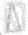
- Fig. 1 is a front view of a side door 1 of a vehicle adopting a door structure according to the present invention and seen from an outer side in a vehicle width direction.
- Fig. 2 is an enlarged cross-sectional view of a main portion of the side door 1 taken along the line A-A in Fig. 1 .
- the arrow F denotes a front-direction of the vehicle
- the arrow U denotes an up-direction of the vehicle
- the arrow OUT denotes an outer side in the vehicle width direction
- the arrow IN denotes an inner side (vehicle compartment side) in the vehicle direction.
- the sign " ⁇ " in Fig. 1 denotes each jointed point where members are joined to each other.
- the side door 1 covers a door opening defined on a lateral surface of a vehicle compartment (lateral side of a seat) in an openable and closable manner. As shown in Fig. 1 , the side door 1 includes a door main body 2 and a door sash 3 provided on the door main body 2.
- the door main body 2 includes an outer panel 4 located on the outer side in the vehicle width direction and an inner panel 5 located in the inner side in the vehicle direction.
- the outer panel 4 is denoted by an imaginary line (long dashed double-dotted line) in Fig. 1 for convenience.
- the door sash 3 defines a window opening 6 ( Fig. 1 ) in cooperation with an upper edge of the door main body 2.
- the door main body 2 supports a window glass 7 ( Fig. 2 ) for opening and closing the window opening 6 in a liftable and lowerable manner.
- the door main body 2 is provided with, in the inside thereof, an unillustrated lifting and lowering device for lifting and lowering the window glass 7.
- the door main body 2 has a substantially rectangular shape as a whole. Specifically, the door main body 2 has a front-side part 51, a rear-side part 52, a top-side part 53, and a bottom-side part 54. A pair of upper and lower hinge brackets 8a, 8b are attached to the front-side part 51 of the door main body 2.
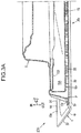
- Fig. 3A is an enlarged cross-sectional view of the main portion of the side door 1 taken along the line B-B in Fig. 1 and seen in the relevant arrow direction.
- the outer panel 4 and the inner panel 5 are connected to each other by swaging at the front-side part 51, the rear-side part 52, and the bottom-side part 54 of the door main body 2.
- a front end 4f of the outer panel 4 and a front end 5f of the inner panel 5 are connected to each other by swaging
- a rear end 4r of the outer panel 4 and a rear end 5r of the inner panel 5 are connected to each other by swaging
- a lower end 4d of the outer panel 4 and a lower end 5d of the inner panel 5 are connected to each other by swaging.
- the rear end 4r of the outer panel 4 has a rear end hem part 10r bent by way of hemming processing as particularly shown in Fig. 3A .
- the rear end hem part 10r is processed to enclose the rear end 5r of the inner panel 5 to thereby connect the rear end 4r of the outer panel 4 and the rear end 5r of the inner panel 5 to each other.
- the front end 4f and the lower end 4d of the outer panel 4 respectively has a front end hem part 10f and a lower end hem part 10d each bent by way of hemming processing.
- the front end hem part 10f and the lower end hem part 10d are processed to respectively enclose the front end 5f and the lower end 5d of the inner panel 5.
- FIG. 3A illustrates only the lower end hem part 10d and the rear end hem part 10r, but it should be noted that the front end hem part 10f has the same shape.
- the door main body 2 is provided with a reinforcement member 11 extending in the front-rear direction in the inside of the top-side part 53, specifically, between an upper end 4u of the outer panel 4 and an upper end 5u of the inner panel 5.
- the reinforcement member 11 reinforces the top-side part 53 (belt line) of the door main body 2, and has an outer belt panel 11 A and an inner belt panel 11B (see Fig. 2 ).
- the two panels 11A, 11B are spaced from each other in the vehicle width direction.
- the outer belt panel 11A is arranged on the outer side of the inner belt panel 11B in the vehicle width direction.
- the outer belt panel 11 A corresponds to an "upper end reinforcement panel" defined in the claims.
- the outer belt panel 11 A and the inner belt panel 11 B define a gap S therebetween for allowing the window glass 7 to slide out or into the door main body 2 when the window glass 7 is lifted or lowered.
- the top-side part 53 of the door main body 2 is engaged with a weather strip 13 for sealing the gap S.
- the upper end 4u of the outer panel 4 and an upper end 11u of the outer belt panel 11 A are connected to each other by swaging at the top-side part 53 of the door main body 2.
- the upper end 4u of the outer panel 4 has an upper end hem part 10u bent by way of hemming processing.
- the upper end hem part 10u is processed to enclose the upper end 11u of the outer belt panel 11 A to thereby connect the upper end 4u of the outer panel 4 and the upper end 11 u of the outer belt panel 11 A to each other.
- connection by swaging at the top-side part 53 of the door main body 2 differs from the connection by swaging at the remaining parts (the front-side part 51, the rear-side part 52, and the bottom-side part 54) of the door main body 2 in that the outer panel 4 and the inner panel 5 are not connected to each other by swaging, but the outer panel 4 and outer belt panel 11 A are connected to each other by swaging.
- the door main body 2 includes a rigid member 9 for enhancing the rigidity thereof.
- the rigid member 9 includes two impact bars 14, 15, and a single door reinforcement panel 21.
- the two impact bars 14, 15 extend from the front-side part 51 to the rear-side part 52 of the door main body 2 in the front-rear direction.
- the impact bars 14, 15 are spaced from each other in the up-down direction, and the impact bar 14 is located above the impact bar 15.
- the impact bar 14 at a higher position is referred to as an upper impact bar 14
- the impact bar 15 at a lower position is referred to as a lower impact bar 15.
- a combination of the upper impact bar 14 and the lower impact bar 15 corresponds to a "door impact bar" defined in the claims.
- the upper impact bar 14 has a front flange 14f and a rear flange 14r.
- the front flange 14f is formed at a front end of the upper impact bar 14, and fixed to the front end 5f of the inner panel 5.
- the rear flange 14r is formed at a rear end of the upper impact bar 14, and fixed to the rear end 5r of the inner panel 5.
- the upper impact bar 14 extends from the front end 5f to the rear end 5r of the inner panel 5 in the front-rear direction.
- the upper impact bar 14 has a plurality of (here, two) protrusions 141 extending in a longitudinal direction of the upper impact bar 14 and protruding outwardly in the vehicle width direction between the flanges 14f, 14r.
- the lower impact bar 15 has a front flange 15f and a rear flange 15r.
- the front flange 15f is formed at a front end of the lower impact bar 15, and fixed to the front end 5f of the inner panel 5.
- the rear flange 15r is formed at a rear end of the lower impact bar 15, and fixed to the rear end 5r of the inner panel 5.
- the lower impact bar 15 extends from the front end 5f to the rear end 5r of the inner panel 5 in the front-rear direction.
- the lower impact bar 15 has a plurality of (here, two) protrusions 151 extending in a longitudinal direction of the lower impact bar 15 and protruding outwardly in the vehicle width direction between the flanges 15f, 15r.
- a hinge reinforcement panel 16 for reinforcing the upper hinge bracket 8a is fixed to an upper portion of the front end 5f of the inner panel 5. Further, a rear sash base 17 serving as a lower end of a rear-side part of the door sash 3 is fixed to an upper portion of the rear end 5r of the inner panel 5.
- the upper impact bar 14 having the front flange 14f joined to an upper portion of the hinge reinforcement panel 16 is fixed to the upper portion of the front end 5f of the inner panel 5 via the hinge reinforcement panel 16.
- the upper impact bar 14 having the rear flange 14rjoined to the rear sash base 17 is fixed to the rear end 5r of the inner panel 5 via the rear sash base 17.
- the upper impact bar 14 linearly extends in such a posture as to be slightly inclined upward to the rear thereof, that is, a posture that the rear end is at a slightly higher position than the front end.
- the upper impact bar 14 extends along the top-side part 53 (upper edge) of the door main body 2 in substantially parallel to the reinforcement member 11 (outer belt panel 11A thereof). As shown in Figs. 1 and 2 , the upper end of the upper impact bar 14 is at the same height as the lower end of the outer belt panel 11A.
- the upper impact bar 14 is at such a height position as to partly overlap the outer belt panel 11A in a door front view (vehicle width directional view), more specifically, is at such a height position that the upper end of the upper impact bar 14 covers the lower end of the outer belt panel 11 A on the outer side in the vehicle width direction.
- a region adjacent to the front end hem part 10f in the door main body 2 is defined as a front hem adjacent region 20f.
- a region adjacent to the rear end hem part 10r in the door main body 2 is defined as a rear hem adjacent region 20r.
- a region adjacent to the upper end hem part 10u in the door main body 2 is defined as an upper hem adjacent region 20u.
- a region adjacent to the lower end hem part 10d in the door main body 2 is referred to as a lower hem adjacent region 20d.
- the upper impact bar 14 is arranged so that the entirety thereof falls within the three hem adjacent regions 20f, 20r, 20u except the lower hem adjacent region 20d.
- the front end of the upper impact bar 14 including the front flange 14f is located in the front hem adjacent region 20f (or the upper hem adjacent region 20u).
- the rear end of the upper impact bar 14 including the rear flange 14r is located in the rear hem adjacent region 20r (or the upper hem adjacent region 20u).
- the main portion of the upper impact bar 14 except the front end and the rear end is located in the upper hem adjacent region 20u.
- the respective hem adjacent regions 20f, 20r, 20u, 20d represent belt-shaped regions each extending along the corresponding hem part (10f, 10r, 10u, 10d) and having a distance of 200 mm or shorter from an inner edge P ( Fig. 2 , Fig 3A ) of the hem part toward a center of the door main body 2.
- the lower impact bar 15 having the front flange 15fjoined to a lower portion of the hinge reinforcement panel 16 is fixed to the upper portion of the front end 5f of the inner panel 5 via the hinge reinforcement panel 16.
- the rear flange 15r of the lower impact bar 15 is fixedly joined to a lower portion of the rear end 5r of the inner panel 5.
- the lower impact bar 15 extends from the front end 5f to the rear end 5r of the inner panel 5 in the front-rear direction.
- Fig. 3B is a perspective view showing the enlarged rear end of the lower impact bar 15.
- the rear flange 15r of the lower impact bar 15 has such a hat-shape in a cross-section as to protrude outwardly in the vehicle width direction.
- a reinforcement plate 152 having a flat shape is joined to the lower impact bar 15 on the inner side of the rear flange 15r in the vehicle direction.
- the rear flange 15r and the reinforcement plate 152 accordingly define an closed cross section 15A (closed cross-sectional space) therebetween.
- the rear flange 15r is joined to the lower portion of the rear end 5r of the inner panel 5 together with the reinforcement plate 152.
- the lower impact bar 15 is arranged so that the front end including the front flange 15f falls within the front hem adjacent region 20f, and the rear end including the rear flange 15r falls within the rear hem adjacent region 20r.
- the lower impact bar 15 linearly extends in such a posture as to be inclined downward to the rear thereof, that is, a posture that the rear end is at a lower position than the front end.
- a distance between the rear end of the upper impact bar 14 and the rear end of the lower impact bar 15 is larger than a distance between the front end of the upper impact bar 14 and the front end of the lower impact bar 15.
- the door reinforcement panel 21 extends from a central portion of the side door 1 including the door main body 2 and the door sash 3 (i.e., a central portion of the top-side part 53 of the door main body 2 in the front-rear direction) to the rear-side part 52 of the door main body 2 in the front-rear direction.
- the door reinforcement panel 21 linearly extends in such a posture as to be inclined downward to the rear thereof, that is, a posture that the rear end is at a lower position than the front end.
- An inclination angle of the door reinforcement panel 21 with respect to a horizontal plane is set to be larger than that of the lower impact bar 15.
- the door reinforcement panel 21 has a front flange 21f and a rear flange 21r.
- the front flange 21f is formed at a front end (upper end) of the door reinforcement panel 21, and fixedly joined to an intermediate portion (around a center in the front-rear direction) of the upper impact bar 14.
- the rear flange 21r is formed at a rear end (lower end) of the door reinforcement panel 21, and fixedly joined to an intermediate portion of the rear end 5r of the inner panel 5 in the up-down direction (above the position where the rear flange 15r of the lower impact bar 15 is joined to the rear end).
- the door reinforcement panel 21 extends from the intermediate portion of the upper impact bar 14 to the rear end 5r of the inner panel 5 in the front-rear direction (up-down direction).
- the door reinforcement panel 21 is arranged so that the rear end including the rear flange 21r falls within the rear hem adjacent region 20r.
- the side door 1 in the embodiment includes a vibration suppression member 22 arranged between the above-described rigid member 9 (the impact bars 14, 15, and the door reinforcement panel 21) and the outer panel 4.
- the vibration suppression member 22 includes a plurality of damping materials 22A, 22B, 22C respectively arranged on the impact bars 14, 15, and the door reinforcement panel 21.
- Each of the damping materials 22A, 22B, 22C is an adhesive called a mastic sealer and having a viscosity.
- the damping materials 22A, 22B, 22C are distributed in the hem adjacent regions 20f, 20r, 20u, and a remaining region (main region including the central portion of the door main body 2) except the hem adjacent regions 20f, 20r, 20u in the door front view (vehicle width directional view).
- the damping materials arranged in the hem adjacent regions 20f, 20r, 20u are colored, and those in the region except the hem adjacent regions 20f, 20r, 20u are colorless.
- a mastic sealer of a high-damping type having a loss coefficient (tan ⁇ ) set to 0.7 or more is adopted for each of the damping materials (colored damping materials 22A, 22B, 22C) arranged in the hem adjacent regions 20f, 20r, 20u and the damping materials (colorless damping materials 22A, 22B, 22C) arranged in the region except the hem adjacent regions 20f, 20r, 20u.
- the vibration suppression member 22 (each of the damping materials 22A, 22B, 22C) is arranged to be in pressure contact with each of the rigid member 9 (the impact bars 14, 15, and the door reinforcement panel 21) and the outer panel 4.
- an uncured paste material being raw material of each of the damping materials 22A, 22B, 22C is applied to designated positions of the rigid member 9, and the outer panel 4 is assembled to the inner panel 5 in this state, so that the outer panel 4 and the rigid member 9 sandwich the paste material.
- the paste material is thermally cured in this state to form the damping materials 22A, 22B, 22C each consisting of a viscous elastic body between the rigid member 9 and the outer panel 4.
- the damping materials 22A are fixedly arranged between the upper impact bar 14 and the outer panel 4 to be in (close) contact with both.
- the damping materials 22B are fixedly arranged between the lower impact bar 15 and the outer panel 4 to be in (close) contact with both.
- the damping materials 22C are fixedly arranged between the door reinforcement panel 21 and the outer panel 4 to be in (close) contact with both.
- the damping materials 22A, 22B, 22C are respectively arrayed in two upper and lower rows in the longitudinal direction of the rigid member 9.
- the damping materials 22A are arrayed along a center line of the upper impact bar 14 inclined upward to the rear thereof and extending in the front-rear direction on an upper side and a lower side across the center line.
- the damping materials 22B are arrayed along a center line of the lower impact bar 15 inclined downward to the rear thereof and extending in the front-rear direction on an upper side and a lower side across the center line.
- the damping materials 22C are arrayed along a center line of the door reinforcement panel 21 inclined downward to the rear thereof and extending in the front-rear direction on an upper side and a lower side across the center line.
- the damping materials 22C are arranged at a plurality of positions including the opposite ends of the door reinforcement panel 21 in the longitudinal direction thereof.
- the two damping materials 22C (colored ones) at the rear end (lower end) of the door reinforcement panel 21 are arranged in the rear hem adjacent region 20r.
- the two damping materials 22C at the front end (upper end) of the door reinforcement panel 21 are arranged around the center of the outer panel 4 in the front-rear direction in the door front view.
- the two damping materials 22C at the front end fulfill the role of improving the panel rigidity of the outer panel 4 made of a thin steel plate in cooperation with the damping materials 22B arranged around the center of the outer panel 4 (the damping materials 22B arranged in a central portion of the lower impact bar 15 in the longitudinal direction thereof).
- the damping materials 22A are staggered in the longitudinal direction of the upper impact bar 14.
- the damping materials 22B are staggered in the longitudinal direction of the lower impact bar 15.
- the damping materials 22A are arranged in two upper and lower rows in the longitudinal direction of the upper impact bar 14, and the damping materials in the upper row and the damping materials in the lower row are arrayed alternately (in a zigzag manner) in the front-rear direction.
- the damping materials 22B are arranged in two upper and lower rows in the longitudinal direction of the lower impact bar 15, and the damping materials in the upper row and the damping materials in the lower row are arrayed alternately (in a zigzag manner) in the front-rear direction.
- the staggered arrangement of the damping materials 22A (22B) aims at maximally increasing an arrangement density (area) of the damping materials 22A (22B) while avoiding an interference between adjacent damping materials 22A (22B).
- a pitch (arrangement interval) between the damping materials 22A (22B) in the respective rows on the impact bar 14 (15) is preferably set to a value equivalent to or smaller than a diameter of each of the damping materials 22A (22B).
- This setting allows a gap between the adjacent damping materials 22A (22B) in the two rows on the impact bar 14 (15) as seen from above or below, that is, a gap between a specific damping material in one of the upper and lower rows and another damping material adjacent thereto in the other row in the front-rear direction, to be as small as possible. Consequently, it is possible to maximally increase the arrangement density (area) of the damping materials 22A (22B) in the front-rear direction.
- the staggered arrangement at the relatively narrow pitch close to the diameter of the damping material 22A (22B) is restricted partly to the damping materials 22A (22B) at the front end and the rear end of the impact bar 14 (15).
- a pith between the damping materials 22A (22B) in the intermediate portion of the impact bar 14 (15) in the front-rear direction is larger than a pitch between the damping materials 22A (22B) on the front end and the rear end of the impact bar 14 (15) in the embodiment (see Fig. 1 ).
- More damping materials 22A (22B) are concentratedly arranged at the front end and the rear end of the impact bar 14 (15) than in the intermediate portion thereof in the front-rear direction in the aforementioned manner to make the arrangement density (area) of the damping materials 22A (22B) in the front hem adjacent region 20f and the rear hem adjacent region 20r be larger than that in other regions.
- the damping materials 22A are staggered at least in a central region of the upper impact bar 14, to which the front end (upper end) of the door reinforcement panel 21 is connected (see the region X in Fig. 1 ), among a region apart from the front end and the rear end of the upper impact bar 14.
- This arrangement of the damping materials 22A at the portion having an increased rigidity owing to the connection between the upper impact bar 14 and the door reinforcement panel 21 brings an encouraged shear deformation of the damping materials 22A at a vibration of the outer panel 4 to be described later, resulting in providing a high vibration suppression effect.
- the upper impact bar 14 is arranged near the top-side part 53 (upper edge) of the door main body 2 so that the entirety thereof falls within the upper hem adjacent region 20u.
- all the damping materials 22A arranged on the upper impact bar 14 fall within the upper hem adjacent region 20u.
- some damping materials 22A at the front end of the upper impact bar 14 fall within the front hem adjacent region 20f, and other damping materials 22A at the rear end of the upper impact bar 14 fall within the rear hem adjacent region 20r.
- the lower impact bar 15 is arranged so that the front end thereof falls within the front hem adjacent region 20f and the rear end thereof falls within the rear hem adjacent region 20r.
- the damping materials 22B colored ones
- the five foremost damping materials 22B fall within the front hem adjacent region 20f
- the six rearmost damping materials 22B fall within the rear hem adjacent region 20r.
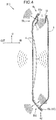
- Fig. 4 is a cross-sectional view of the main portion taken along the line D-D in Fig. 1 , and schematically shows the operation of the embodiment.
- Fig. 4 shows a cross section of the door main body 2 in a state where the vibration suppression member 22 (damping materials 22A to 22C) is removed therefrom without the illustration of the upper and lower impact bars 14, 15.
- an engine sound, a tire sound, or a wind sound transmitted to the side door 1 via an air causes an excitation force to act from the outer side in the vehicle width direction to the outer panel 4 of the door main body 2.
- the thin outer panel 4 slightly vibrates in response to the excitation force.
- the outer panel 4 slightly vibrates when the side door 1 in an open state is closed as well.
- the central portion of the outer panel 4 is away from the hem parts 10f, 10r, 10u, 10d restrained by the connection by swaging, and thus the vibration occurring in the central portion of the outer panel 4 has a large amplitude and a low frequency.
- the vibration occurring on the periphery of the outer panel 4 adjacent to the hem parts 10f, 10r, 10u, 10d (falling within the hem adjacent regions 20f, 20r, 20u, 20d) has a small amplitude and a high frequency.
- the slight vibration of the outer panel 4 generates a radiant sound with a low frequency of about 125 Hz or lower from the central portion of the outer panel 4 and a radiant sound with a middle/high frequency exceeding about 125 Hz from the periphery of the outer panel 4.
- the difference seen in the frequencies (amplitudes), that is, the relatively higher frequency on the periphery of the outer panel 4 (with the relatively smaller amplitude), means that a strain energy in the hem adjacent regions 20f, 20r, 20u, 20d is larger than a strain energy in the remaining regions other than the hem adjacent regions.
- the vibration suppression member 22 (each of the damping materials 22A to 22C) is concentratedly arranged in each of the hem adjacent regions 20f, 20r, 20u (see Fig. 1 ) in the embodiment as described above.
- the concentrated arrangement of the damping materials 22A to 22C in the hem adjacent regions 20f, 20r, 20u having the relatively large strain energy encourages the shear deformation of the damping materials 22A to 22C interposed between the outer panel 4 and the rigid member 9 (impact bars 14, 15, and the door reinforcement panel 21), resulting in attaining a high vibration suppression effect.
- an arrangement of damping materials in the central portion (region other than the hem adjacent regions 20f, 20r, 20u, 20d) of the outer panel 4 causes the damping materials to be displaced integrally with the central portion of the outer panel 4 which vibrates at a relatively large amplitude. Accordingly, the amount of shear deformation of the damping materials is small regardless of the large amplitude.
- another arrangement of the damping materials in the hem adjacent regions 20f, 20r, 20u causes the damping materials to be displaced in an undulation manner relative to the impact bars 14, 15, and door reinforcement panel 21. As a result, large shear deformation of the damping material occurs.
- the concentrated arrangement of the damping materials 22A to 22C in the hem adjacent regions 20f, 20r, 20u as in the embodiment can efficiently suppress the vibration of the outer panel 4 caused by the excitation force from the outer side in the vehicle width direction and effectively reduce a noise having a middle/high frequency to enter the vehicle compartment during the running of the vehicle.
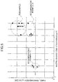
- Fig. 5 is a graph showing a relation between a transmission loss of the outer panel 4 and a loss coefficient (tan ⁇ ) of the damping material when the outer panel 4 of the side door 1 is vibrated as shown in Fig. 4 .
- the plots included in the region R1 in Fig. 5 represent measurement results of a plurality of samples (hereinafter, referred to as "Comparative Example 1") each having a conventional door structure where damping materials having a loss coefficient of 0.2 are concentratedly arranged around the center of the outer panel 4 to improve a panel rigidity of the outer panel 4.
- Example 5 represent measurement results of a plurality of different samples (hereinafter, referred to as "Comparative Example 2") each having a conventional door structure where damping materials (mastic sealers of a high-damping type) having a loss coefficient of 0.7 are concentratedly arranged around the center of the outer panel 4.
- the plots included in the region R3 in Fig. 5 represent measurement results of a plurality of samples (hereinafter, referred to as "Example”) each having a door structure according to the embodiment shown in Fig. 1 to Fig. 3B where the damping materials 22A to 22C having a loss coefficient of 0.7 are concentratedly arranged in the hem adjacent regions 20f, 20r, 20u of the outer panel 4.
- Comparative Example 2 is common with Comparative Example 1 in the concentrated arrangement of the damping materials around the center of the outer panel 4, but differs therefrom in the larger loss coefficient of the damping materials. Specifically, the loss coefficient in the Comparative Example 2 is set to 0.7 that is larger than the loss coefficient of 0.2 in Comparative Example 1. A panel transmission loss in Comparative Example 2 is larger than that in Comparative Example 1 due to the difference, but a rate of increase in the panel transmission loss is very small (see the respective plots in the regions R1, R2).
- Example is common with Comparative Example 2 in the damping materials having the loss coefficient of 0.7, but differs from Comparative Example 2 in the regions where the damping materials are concentratedly arranged. Specifically, the damping materials are concentratedly arranged in the hem adjacent regions 20f, 20r, 20u in Example, while the damping materials are concentratedly arranged around the center of the outer panel 4 in Comparative Example 2.
- the transmission loss in Example is larger than that in Comparative Example 2 due to the difference (see the respective plots in the regions R2, R3). Moreover, a rate of increase in the transmission loss from Comparative Example 2 to Example is higher than that from Comparative Example 1 to Comparative Example 2.
- the concentrated arrangement of the damping materials around the center of the outer panel 4 is too restrictive to satisfactorily improve the vibration suppression effect even with an increased loss coefficient of the damping materials.
- the concentrated arrangement of the damping materials 22A to 22C in the hem adjacent regions 20f, 20r, 20u of the outer panel 4 as in the embodiment is confirmed to be efficient for the vibration suppression.
- the door structure of the vehicle includes: the outer panel 4; the inner panel 5 and the outer belt panel 11A arranged on the inner side of the outer panel 4 in the vehicle width direction; the rigid member 9 (impact bars 14, 15, and door reinforcement panel 21) arranged between the inner panel 5 and the outer panel 4; and the vibration suppression member 22 arranged between the outer panel 4 and the rigid member 9.
- the outer panel 4 includes the hem parts 10f, 10r, 10u disposed on the periphery thereof and connected to the inner panel 5 or the outer belt panel 11A by swaging.
- the vibration suppression member 22 includes the damping materials 22A to 22C sandwiched between the outer panel 4 and the rigid member 9 in contact with both, and some damping materials 22A to 22C (colored ones shown in Fig.
- the arrangement of the damping materials 22A to 22C in the hem adjacent regions 20f, 20r, 20u where the strain energy is likely to be accumulated at the vibration of the outer panel 4 enables the damping materials 22A to 22C to efficiently convert the strain energy to heat.
- the strain energy in the hem adjacent regions 20f, 20r, 20u is thus sufficiently absorbed. It is consequently possible to enhance the vibration suppression effect of the outer panel 4 owing to the damping materials 22A to 22C. Thus, a noise (particularly, a noise having a middle/high frequency) transmitted from the side door 1 into the vehicle compartment can be effectively reduced.
- the damping materials 22A, 22B are arranged on the impact bars 14, 15 (door impact bar) extending from the front end 5f to the rear end 5r of the inner panel 5.
- the arrangement of the damping materials 22A, 22B on the impact bars 14, 15 each having the high rigidity (i.e., being less likely to deform) can encourage the shear deformation of the damping materials 22A, 22B located between the outer panel 4 and the impact bars 14, 15 at the vibration of the outer panel 4, and hence can sufficiently enhance the vibration suppression effect.
- the outer belt panel 11 A is arranged between the upper end of the inner panel 5 and the upper end of the outer panel 4 and extending in the front-rear direction.
- the upper end hem part 10u of the outer panel 4 is connected to the upper end 11u of the outer belt panel 11 A by swaging.
- the upper impact bar 14 is arranged in the upper hem adjacent region 20u adjacent to the upper end hem part 10u to extend in the front-rear direction.
- the damping materials 22A are arrayed in the longitudinal direction of the upper impact bar 14 (see Fig. 1 and Fig. 2 ).
- the arrangement of the damping materials 22A on the upper impact bar 14 in the upper hem adjacent region 20u in the aforementioned manner enables the damping materials 22A to sufficiently absorb the strain energy to occur in the upper hem adjacent region 20u at the vibration of the outer panel 4, and effectively suppress the bibation of the outer panel 4.
- the door reinforcement panel 21 extends from the intermediate portion in the front-rear direction of the upper impact bar 14 to the rear end 5r of the inner panel 5.
- the rear end hem part 10r of the outer panel 4 is connected to the rear end 5r of the inner panel 5 by swaging.
- a part of the damping materials 22C is located at the rear end of the door reinforcement panel 21 falling within the rear hem adjacent region 20r adjacent to the rear end hem part 10r (see Fig. 1 ).
- the damping materials 22C arranged between the rear end of the door reinforcement panel 21 and the outer panel 4 as well as between the upper and lower impact bars 14, 15 and the outer panel 4 in this manner can sufficiently absorb the strain energy to occur in the rear hem adjacent region 20r at the vibration of the outer panel 4, and effectively suppress the vibration of the outer panel 4.
- the damping materials 22A, 22B are staggered in the longitudinal direction of each of the upper and lower impact bars 14, 15 in the embodiment (see Fig. 1 ).
- This configuration can provide the arrangement of many damping materials 22A, 22B with a minimal gap therebetween in the front-rear direction and reliably ensure the vibration suppression effect owing to the damping materials 22A, 22B while guaranteeing the shape and the quality of the damping materials 22A, 22B having been cured.
- this configuration can increase the arrangement density (area) of the damping materials 22A (22B) even in the arrangement of the damping materials 22A (22B) without the interference between the adjacent damping materials 22A (22B) on the impact bar 14 (15). This consequently makes it possible to provide an excellent vibration suppression effect.
- a mastic sealer of a high-damping type having a loss coefficient (tan ⁇ ) of 0.7 or more is adopted for each of the damping materials 22A to 22C.
- the arrangement of the damping materials 22A to 22C each made of the mastic sealer of the high-damping type in the respective parts of the door main body 2 including the hem adjacent regions 20f, 20r, 20u can notably enhance the vibration suppression effect of the outer panel 4.
- Fig. 6A is a cross-sectional view showing a structure of a side door 1A according to the first modification.
- the side door 1A according to the first modification includes an outer belt panel 11A' having a different shape from the outer belt panel 11 A in the embodiment, and a plurality of damping materials 22D between the outer belt panel 11A' and the outer panel 4.
- the outer belt panel 11A' has, in its lower portion, a lower extension 111 located adjacent to the outer panel 4 and extending downward along the outer panel 4.
- the lower extension 111 has a pair of upper and lower support parts 111a, 111b protruding toward the outer panel 4.
- the support parts 111a, 111b face the outer panel 4 to define a space therebetween for receiving the damping materials 22D placed therein.
- the damping materials 22D are arranged between the upper support part 111a and the outer panel 4, and between the lower support part 111b and the outer panel 4 in the front-rear direction (arrayed in two upper and lower rows). More specifically, the damping materials 22D are arranged so that the damping materials 22D on the support part 111a in the upper row and the damping materials 22D on the support part 111b in the lower row are alternated (staggered) in the front-rear direction.
- the damping materials 22D are arranged on the outer belt panel 11A' located above the upper impact bar 14. This arrangement enables the damping materials 22D to be closer to the upper end hem part 10u of the outer panel 4 and more efficiently absorb the strain energy in the upper hem adjacent region 20u at the vibration of the outer panel 4. That is to say, it is possible to efficiently convert the strain energy in the upper hem adjacent region 20u to heat, and enhance the vibration suppression effect of the outer panel 4.
- the damping materials 22D in the first modification may be arranged on the outer belt panel 11A' in place of the damping materials 22A on the upper impact bar 14, or may be arranged on the outer belt panel 11A' in addition to the damping materials 22A on the upper impact bar 14.
- the damping materials may be arranged on either the upper impact bar 14 or the outer belt panel 11A', or may be arranged on both the upper impact bar 14 and the outer belt panel 11A'.
- Fig. 6B is a cross-sectional view showing a structure of a side door 1B according to the second modification.
- the side door 1B according to the second modification includes a rigid member 30 made of aluminum having a thickness which is relatively large in the vehicle width direction (with a relatively large weight).
- the rigid member 30 is adhered to the outer panel 4 via a plurality of damping materials 22E without being attached to other door structural component.
- the rigid member 30 and the outer panel 4 are integrated via the damping materials 22E to form a three-layered cross-sectional structure in the vehicle width direction.
- the damping materials 22E are arrayed in two upper and lower rows in the longitudinal direction (front-rear direction) of the rigid member 30. More specifically, the damping materials 22E are arranged so that the damping materials 22E in the upper row and the damping materials 22E in the lower row are alternated (staggered) in the front-rear direction.
- the structure according to the second modification can encourage the shear deformation of the damping materials 22E arranged between the rigid member 30 and the outer panel 4 by using the inertia of the rigid member 30.
- the damping materials 22E in this arrangement is caused to generate an internal friction to thereby succeed in absorbing the strain energy and further enhancing the vibration suppression effect of the outer panel 4.
- the present invention further includes the following modifications.
- the viscoelastic member made of a mastic sealer and having a relatively large thickness is adopted for each of the damping materials 22A to 22C arranged between the rigid member 9 and the outer panel 4 in the embodiment, a thin sheet-shaped viscoelastic member may be used as the damping material.
- the material for the damping material is not limited thereto.
- a mastic sealer of a low-damping type having a loss coefficient of less than 0.7 e.g., about 0.2
- the mastic sealer of the high-damping type and the mastic sealer of the low-damping type may be adopted in combination.
- damping materials 22A to 22C are distributed to respective parts of the rigid member 9 (impact bars 14, 15, and the door reinforcement panel 21) so that some of the damping materials 22A to 22C (colored ones in Fig. 1 ) fall within the front hem adjacent region 20f, the rear hem adjacent region 20r, and the upper hem adjacent region 20u in the embodiment, an additional rigid member may be provided in the lower hem adjacent region 20d, and additional damping materials may be arranged on the additional rigid member.
- a door structure of a vehicle includes: an outer panel; an inner member arranged on an inner side of the outer panel in a vehicle width direction; a rigid member arranged between the inner member and the outer panel; and a vibration suppression member arranged between the outer panel and the rigid member.
- the outer panel includes a hem section disposed on a periphery thereof and connected to the inner member by swaging.
- the vibration suppression member includes a damping material located adjacent to the hem section and being in contact with the outer panel and the rigid member.
- the arrangement of the damping materials in the region adjacent to the hem section where the strain energy is likely to be accumulated at the vibration of the outer panel enables the damping materials to efficiently convert the strain energy to heat.
- the strain energy in the region adjacent to the hem section is thus sufficiently absorbed. It is consequently possible to enhance the vibration suppression effect of the outer panel owing to the damping materials. Thus, a noise (particularly, a noise having the middle/high frequency) transmitted from the side door into the vehicle compartment can be effectively reduced.
- the inner member includes an inner panel
- the rigid member includes a door impact bar extending from a front end to a rear end of the inner panel.
- the arrangement of the damping materials on the door impact bar having the high rigidity can encourage the shear deformation of the damping materials located between the outer panel and the door impact bar at the vibration of the outer panel, and hence can sufficiently enhance the vibration suppression effect.
- the inner member includes the inner panel, and an upper end reinforcement panel arranged between an upper end of the inner panel and an upper end of the outer panel and extending in a front-rear direction
- the hem section has an upper end hem part connected to an upper end of the upper end reinforcement panel by swaging
- the door impact bar includes an upper impact bar located adjacent to the upper end hem part and extending in the front-rear direction
- the vibration suppression member includes a plurality of the damping materials arrayed in a longitudinal direction of the upper impact bar.
- the arrangement of the damping materials on the upper impact bar located adjacent to the upper end hem part enables the damping materials to sufficiently absorb the strain energy to occur in the region adjacent to the upper end hem part at the vibration of the outer panel, and effectively suppress the vibration of the outer panel.
- the rigid member includes the upper impact bar and a door reinforcement panel extending from an intermediate portion of the upper impact bar to the rear end of the inner panel, the hem section has a rear end hem part connected to the rear end of the inner panel by swaging, and the vibration suppression member includes the damping material located adjacent to the rear end hem part at a rear end of the door reinforcement panel.
- the damping materials arranged between the rear end of the door reinforcement panel and the outer panel as well as between the upper impact bar and the outer panel can sufficiently absorb the strain energy to occur in the region adjacent to the rear end hem part at the vibration of the outer panel, and effectively suppress the vibration of the outer panel.
- the vibration suppression member includes a plurality of the damping materials staggered in a longitudinal direction of the rigid member.
- This configuration can achieve the arrangement of many damping materials with a minimal gap therebetween and reliably ensure a sufficient vibration suppression effect by the damping materials while facilitating the shaping and quality management of the damping materials sandwiched (compressed) between the rigid member and the outer panel.
- this configuration can increase the arrangement density (area) of the damping materials without an interference between the adjacent damping materials, thereby providing an excellent vibration suppression effect.
- the damping material includes a mastic sealer of a high-damping type having a loss coefficient (tan ⁇ ) of 0.7 or more.
- the arrangement of the damping material made of the mastic sealer of the high-damping type in the region adjacent to the hem section can prominently enhance the vibration suppression effect of the outer panel.
Landscapes
- Engineering & Computer Science (AREA)
- Mechanical Engineering (AREA)
- Body Structure For Vehicles (AREA)
Abstract
Description
- The present invention relates to a door structure of a vehicle including: an outer panel; an inner member arranged on an inner side of the outer panel in a vehicle width direction; and a rigid member arranged between the inner member and the outer panel.
- During running of a vehicle, an excitation force caused by, for example, an engine sound, a tire sound, or a wind sound transmitted to a door via an air acts on an outer panel of the door from an outer side in a vehicle width direction. The outer panel of the door is typically a thin plate. Hence, the excitation force may cause the outer panel to vibrate, and a radiant sound attributed to the vibration may be accordingly emitted from the outer panel. The radiant sound from the outer panel is transmitted into a vehicle compartment as a noise. The same situation can occur when the door in an open state is closed.
- Increasing the thickness of the outer panel can reduce the noise transmitted into the vehicle compartment due to the aforementioned mechanism. However, such an increase in the thickness of the outer panel is directly linked to an increase in the weight of the vehicle, which is unfavorable. Under the circumstances, techniques capable of suppressing the vibration without increasing the thickness of the outer panel have been demanded.
- In contrast, it has been also known to provide a damping material in an inner part of a door, as disclosed in
Patent Literature 1, for allowing an outer panel to have a panel rigidity. - Specifically, in
Patent Literature 1, an adhesive serving as a damping material is provided between the outer panel and a door beam (door impact bar). The adhesive is arranged at a plurality of positions except a front end and a rear end of the outer panel (see, for example,Fig. 1A of Patent Literature 1). - According to the door structure of
Patent Literature 1, a strain energy of the outer panel is deduced to be partly converted to heat with the adhesive arranged in the aforementioned manner. This configuration is expected to provide some effects of suppressing the vibration of the outer panel. - However,
Patent Literature 1 fails to particularly consider a preferable arrangement of the adhesive to enhance a vibration suppression effect of the outer panel. In other words, the arrangement of the adhesive disclosed inPatent Literature 1 does not always efficiently exert the vibration suppression effect, and hence has room for improvement. - Patent Literature 1:
Japanese Unexamined Patent Publication No. 2018-90061 - The present invention has been made in consideration of the aforementioned circumstances, and has an object to provide a door structure of a vehicle which can enhance a vibration suppression effect of an outer panel by using a damping material and thereby reduce a noise transmitted from a door into a vehicle compartment as much as possible.
- A door structure of a vehicle according to the present invention for achieving the object includes: an outer panel; an inner member arranged on an inner side of the outer panel in a vehicle width direction; a rigid member arranged between the inner member and the outer panel; and a vibration suppression member arranged between the outer panel and the rigid member. The outer panel includes a hem section disposed on a periphery thereof and connected to the inner member by swaging. The vibration suppression member includes a damping material located adjacent to the hem section and being in contact with the outer panel and the rigid member.
-
-
Fig. 1 is a front view of a side door having a door structure of a vehicle according to an embodiment of the present invention with an outer panel being denoted by an imaginary line. -
Fig. 2 is an enlarged cross-sectional view of a main portion taken along the line A-A inFig. 1 -
Fig. 3A is an enlarged cross-sectional view of the main portion taken along the line B-B inFig. 1 and seen in the relevant arrow direction. -
Fig. 3B is a perspective view showing an enlarged rear end of a lower impact bar. -
Fig. 4 is an explanatory cross-sectional view of the main portion taken along the line D-D inFig. 1 , and schematically shows the operation in the embodiment. -
Fig. 5 is a graph showing a relation between a transmission loss of the outer panel and a loss coefficient of a damping material. -
Fig. 6A corresponding toFig. 2 shows a first modification of the door structure according to the embodiment. -
Fig. 6B corresponding toFig. 2 shows a second modification of the door structure according to the embodiment. - Hereinafter, an embodiment of the present invention will be described with reference to the accompanying drawings.
-
Fig. 1 is a front view of aside door 1 of a vehicle adopting a door structure according to the present invention and seen from an outer side in a vehicle width direction.Fig. 2 is an enlarged cross-sectional view of a main portion of theside door 1 taken along the line A-A inFig. 1 . In the drawings, the arrow F denotes a front-direction of the vehicle, the arrow U denotes an up-direction of the vehicle, the arrow OUT denotes an outer side in the vehicle width direction, and the arrow IN denotes an inner side (vehicle compartment side) in the vehicle direction. Furthermore, the sign "×" inFig. 1 denotes each jointed point where members are joined to each other. - The
side door 1 covers a door opening defined on a lateral surface of a vehicle compartment (lateral side of a seat) in an openable and closable manner. As shown inFig. 1 , theside door 1 includes a doormain body 2 and a door sash 3 provided on the doormain body 2. - As shown in
Figs. 1 and2 , the doormain body 2 includes anouter panel 4 located on the outer side in the vehicle width direction and aninner panel 5 located in the inner side in the vehicle direction. Theouter panel 4 is denoted by an imaginary line (long dashed double-dotted line) inFig. 1 for convenience. - The door sash 3 defines a window opening 6 (
Fig. 1 ) in cooperation with an upper edge of the doormain body 2. The doormain body 2 supports a window glass 7 (Fig. 2 ) for opening and closing the window opening 6 in a liftable and lowerable manner. The doormain body 2 is provided with, in the inside thereof, an unillustrated lifting and lowering device for lifting and lowering the window glass 7. - As shown in
Fig. 1 , the doormain body 2 has a substantially rectangular shape as a whole. Specifically, the doormain body 2 has a front-side part 51, a rear-side part 52, a top-side part 53, and a bottom-side part 54. A pair of upper andlower hinge brackets side part 51 of the doormain body 2. -
Fig. 3A is an enlarged cross-sectional view of the main portion of theside door 1 taken along the line B-B inFig. 1 and seen in the relevant arrow direction. As shown inFig. 3A and the precedingFig. 1 , theouter panel 4 and theinner panel 5 are connected to each other by swaging at the front-side part 51, the rear-side part 52, and the bottom-side part 54 of the doormain body 2. Specifically, afront end 4f of theouter panel 4 and afront end 5f of theinner panel 5 are connected to each other by swaging, arear end 4r of theouter panel 4 and arear end 5r of theinner panel 5 are connected to each other by swaging, and alower end 4d of theouter panel 4 and alower end 5d of theinner panel 5 are connected to each other by swaging. - More specifically, the
rear end 4r of theouter panel 4 has a rearend hem part 10r bent by way of hemming processing as particularly shown inFig. 3A . The rearend hem part 10r is processed to enclose therear end 5r of theinner panel 5 to thereby connect therear end 4r of theouter panel 4 and therear end 5r of theinner panel 5 to each other. Similarly, thefront end 4f and thelower end 4d of theouter panel 4 respectively has a frontend hem part 10f and a lowerend hem part 10d each bent by way of hemming processing. The frontend hem part 10f and the lowerend hem part 10d are processed to respectively enclose thefront end 5f and thelower end 5d of theinner panel 5. In this way, thefront end 4f of theouter panel 4 and thefront end 5f of theinner panel 5 are connected to each other, and thelower end 4d of theouter panel 4 and thelower end 5d of theinner panel 5 are connected to each other.Fig. 3A illustrates only the lowerend hem part 10d and the rearend hem part 10r, but it should be noted that the frontend hem part 10f has the same shape. - As shown in
Figs. 1 and2 , the doormain body 2 is provided with areinforcement member 11 extending in the front-rear direction in the inside of the top-side part 53, specifically, between anupper end 4u of theouter panel 4 and anupper end 5u of theinner panel 5. - The
reinforcement member 11 reinforces the top-side part 53 (belt line) of the doormain body 2, and has anouter belt panel 11 A and aninner belt panel 11B (seeFig. 2 ). The twopanels outer belt panel 11A is arranged on the outer side of theinner belt panel 11B in the vehicle width direction. Theouter belt panel 11 A corresponds to an "upper end reinforcement panel" defined in the claims. - The
outer belt panel 11 A and theinner belt panel 11 B define a gap S therebetween for allowing the window glass 7 to slide out or into the doormain body 2 when the window glass 7 is lifted or lowered. As denoted by the imaginary line inFig. 2 , the top-side part 53 of the doormain body 2 is engaged with aweather strip 13 for sealing the gap S. - As shown in
Fig. 2 , theupper end 4u of theouter panel 4 and anupper end 11u of theouter belt panel 11 A are connected to each other by swaging at the top-side part 53 of the doormain body 2. Specifically, theupper end 4u of theouter panel 4 has an upperend hem part 10u bent by way of hemming processing. The upperend hem part 10u is processed to enclose theupper end 11u of theouter belt panel 11 A to thereby connect theupper end 4u of theouter panel 4 and theupper end 11 u of theouter belt panel 11 A to each other. In this respect, the connection by swaging at the top-side part 53 of the doormain body 2 differs from the connection by swaging at the remaining parts (the front-side part 51, the rear-side part 52, and the bottom-side part 54) of the doormain body 2 in that theouter panel 4 and theinner panel 5 are not connected to each other by swaging, but theouter panel 4 andouter belt panel 11 A are connected to each other by swaging. - As shown in
Fig. 1 , the doormain body 2 includes arigid member 9 for enhancing the rigidity thereof. Therigid member 9 includes two impact bars 14, 15, and a singledoor reinforcement panel 21. - The two impact bars 14, 15 extend from the front-
side part 51 to the rear-side part 52 of the doormain body 2 in the front-rear direction. The impact bars 14, 15 are spaced from each other in the up-down direction, and theimpact bar 14 is located above theimpact bar 15. Hereinafter, theimpact bar 14 at a higher position is referred to as anupper impact bar 14 and theimpact bar 15 at a lower position is referred to as alower impact bar 15. A combination of theupper impact bar 14 and thelower impact bar 15 corresponds to a "door impact bar" defined in the claims. - As shown in
Fig. 1 , theupper impact bar 14 has afront flange 14f and arear flange 14r. Thefront flange 14f is formed at a front end of theupper impact bar 14, and fixed to thefront end 5f of theinner panel 5. Therear flange 14r is formed at a rear end of theupper impact bar 14, and fixed to therear end 5r of theinner panel 5. In other words, theupper impact bar 14 extends from thefront end 5f to therear end 5r of theinner panel 5 in the front-rear direction. Furthermore, theupper impact bar 14 has a plurality of (here, two)protrusions 141 extending in a longitudinal direction of theupper impact bar 14 and protruding outwardly in the vehicle width direction between theflanges - Similarly, the
lower impact bar 15 has afront flange 15f and arear flange 15r. Thefront flange 15f is formed at a front end of thelower impact bar 15, and fixed to thefront end 5f of theinner panel 5. Therear flange 15r is formed at a rear end of thelower impact bar 15, and fixed to therear end 5r of theinner panel 5. In other words, thelower impact bar 15 extends from thefront end 5f to therear end 5r of theinner panel 5 in the front-rear direction. Furthermore, thelower impact bar 15 has a plurality of (here, two)protrusions 151 extending in a longitudinal direction of thelower impact bar 15 and protruding outwardly in the vehicle width direction between theflanges - A
hinge reinforcement panel 16 for reinforcing theupper hinge bracket 8a is fixed to an upper portion of thefront end 5f of theinner panel 5. Further, arear sash base 17 serving as a lower end of a rear-side part of the door sash 3 is fixed to an upper portion of therear end 5r of theinner panel 5. Theupper impact bar 14 having thefront flange 14f joined to an upper portion of thehinge reinforcement panel 16 is fixed to the upper portion of thefront end 5f of theinner panel 5 via thehinge reinforcement panel 16. Theupper impact bar 14 having the rear flange 14rjoined to therear sash base 17 is fixed to therear end 5r of theinner panel 5 via therear sash base 17. - The
upper impact bar 14 linearly extends in such a posture as to be slightly inclined upward to the rear thereof, that is, a posture that the rear end is at a slightly higher position than the front end. Theupper impact bar 14 extends along the top-side part 53 (upper edge) of the doormain body 2 in substantially parallel to the reinforcement member 11 (outer belt panel 11A thereof). As shown inFigs. 1 and2 , the upper end of theupper impact bar 14 is at the same height as the lower end of theouter belt panel 11A. In other words, theupper impact bar 14 is at such a height position as to partly overlap theouter belt panel 11A in a door front view (vehicle width directional view), more specifically, is at such a height position that the upper end of theupper impact bar 14 covers the lower end of theouter belt panel 11 A on the outer side in the vehicle width direction. - A region adjacent to the front
end hem part 10f in the doormain body 2 is defined as a front hemadjacent region 20f. A region adjacent to the rearend hem part 10r in the doormain body 2 is defined as a rear hemadjacent region 20r. A region adjacent to the upperend hem part 10u in the doormain body 2 is defined as an upper hemadjacent region 20u. A region adjacent to the lowerend hem part 10d in the doormain body 2 is referred to as a lower hemadjacent region 20d. Theupper impact bar 14 is arranged so that the entirety thereof falls within the three hemadjacent regions adjacent region 20d. That is to say, the front end of theupper impact bar 14 including thefront flange 14f is located in the front hemadjacent region 20f (or the upper hemadjacent region 20u). The rear end of theupper impact bar 14 including therear flange 14r is located in the rear hemadjacent region 20r (or the upper hemadjacent region 20u). The main portion of theupper impact bar 14 except the front end and the rear end is located in the upper hemadjacent region 20u. The respective hemadjacent regions Fig. 2 ,Fig 3A ) of the hem part toward a center of the doormain body 2. - As shown in
Fig. 1 , thelower impact bar 15 having the front flange 15fjoined to a lower portion of thehinge reinforcement panel 16 is fixed to the upper portion of thefront end 5f of theinner panel 5 via thehinge reinforcement panel 16. Therear flange 15r of thelower impact bar 15 is fixedly joined to a lower portion of therear end 5r of theinner panel 5. In other words, thelower impact bar 15 extends from thefront end 5f to therear end 5r of theinner panel 5 in the front-rear direction. -
Fig. 3B is a perspective view showing the enlarged rear end of thelower impact bar 15. As shown in this figure, therear flange 15r of thelower impact bar 15 has such a hat-shape in a cross-section as to protrude outwardly in the vehicle width direction. Areinforcement plate 152 having a flat shape is joined to thelower impact bar 15 on the inner side of therear flange 15r in the vehicle direction. Therear flange 15r and thereinforcement plate 152 accordingly define anclosed cross section 15A (closed cross-sectional space) therebetween. As shown inFigs. 1 and3A , therear flange 15r is joined to the lower portion of therear end 5r of theinner panel 5 together with thereinforcement plate 152. - As shown in
Fig. 1 , thelower impact bar 15 is arranged so that the front end including thefront flange 15f falls within the front hemadjacent region 20f, and the rear end including therear flange 15r falls within the rear hemadjacent region 20r. - The
lower impact bar 15 linearly extends in such a posture as to be inclined downward to the rear thereof, that is, a posture that the rear end is at a lower position than the front end. A distance between the rear end of theupper impact bar 14 and the rear end of thelower impact bar 15 is larger than a distance between the front end of theupper impact bar 14 and the front end of thelower impact bar 15. This configuration provides the operational effect of efficiently receiving an impact load input to the doormain body 2 at a side collision of the vehicle. - As shown in
Fig. 1 , thedoor reinforcement panel 21 extends from a central portion of theside door 1 including the doormain body 2 and the door sash 3 (i.e., a central portion of the top-side part 53 of the doormain body 2 in the front-rear direction) to the rear-side part 52 of the doormain body 2 in the front-rear direction. - The
door reinforcement panel 21 linearly extends in such a posture as to be inclined downward to the rear thereof, that is, a posture that the rear end is at a lower position than the front end. An inclination angle of thedoor reinforcement panel 21 with respect to a horizontal plane is set to be larger than that of thelower impact bar 15. - The
door reinforcement panel 21 has afront flange 21f and arear flange 21r. Thefront flange 21f is formed at a front end (upper end) of thedoor reinforcement panel 21, and fixedly joined to an intermediate portion (around a center in the front-rear direction) of theupper impact bar 14. Therear flange 21r is formed at a rear end (lower end) of thedoor reinforcement panel 21, and fixedly joined to an intermediate portion of therear end 5r of theinner panel 5 in the up-down direction (above the position where therear flange 15r of thelower impact bar 15 is joined to the rear end). In other words, thedoor reinforcement panel 21 extends from the intermediate portion of theupper impact bar 14 to therear end 5r of theinner panel 5 in the front-rear direction (up-down direction). - As shown in
Fig. 1 , thedoor reinforcement panel 21 is arranged so that the rear end including therear flange 21r falls within the rear hemadjacent region 20r. - As shown in
Figs. 1 to 3B , theside door 1 in the embodiment includes avibration suppression member 22 arranged between the above-described rigid member 9 (the impact bars 14, 15, and the door reinforcement panel 21) and theouter panel 4. Thevibration suppression member 22 includes a plurality of dampingmaterials door reinforcement panel 21. Each of the dampingmaterials - The damping
materials adjacent regions adjacent regions Fig. 1 , the damping materials arranged in the hemadjacent regions adjacent regions materials adjacent regions materials adjacent regions - As shown in
Figs. 1 to 3A , the vibration suppression member 22 (each of the dampingmaterials outer panel 4. Specifically, an uncured paste material being raw material of each of the dampingmaterials rigid member 9, and theouter panel 4 is assembled to theinner panel 5 in this state, so that theouter panel 4 and therigid member 9 sandwich the paste material. Moreover, the paste material is thermally cured in this state to form the dampingmaterials rigid member 9 and theouter panel 4. The dampingmaterials 22A are fixedly arranged between theupper impact bar 14 and theouter panel 4 to be in (close) contact with both. The dampingmaterials 22B are fixedly arranged between thelower impact bar 15 and theouter panel 4 to be in (close) contact with both. The dampingmaterials 22C are fixedly arranged between thedoor reinforcement panel 21 and theouter panel 4 to be in (close) contact with both. - As shown in
Figs. 1 to 3B , the dampingmaterials rigid member 9. Specifically, the dampingmaterials 22A are arrayed along a center line of theupper impact bar 14 inclined upward to the rear thereof and extending in the front-rear direction on an upper side and a lower side across the center line. The dampingmaterials 22B are arrayed along a center line of thelower impact bar 15 inclined downward to the rear thereof and extending in the front-rear direction on an upper side and a lower side across the center line. The dampingmaterials 22C are arrayed along a center line of thedoor reinforcement panel 21 inclined downward to the rear thereof and extending in the front-rear direction on an upper side and a lower side across the center line. - As shown in
Fig. 1 , the dampingmaterials 22C are arranged at a plurality of positions including the opposite ends of thedoor reinforcement panel 21 in the longitudinal direction thereof. The two dampingmaterials 22C (colored ones) at the rear end (lower end) of thedoor reinforcement panel 21 are arranged in the rear hemadjacent region 20r. The two dampingmaterials 22C at the front end (upper end) of thedoor reinforcement panel 21 are arranged around the center of theouter panel 4 in the front-rear direction in the door front view. The two dampingmaterials 22C at the front end fulfill the role of improving the panel rigidity of theouter panel 4 made of a thin steel plate in cooperation with the dampingmaterials 22B arranged around the center of the outer panel 4 (the dampingmaterials 22B arranged in a central portion of thelower impact bar 15 in the longitudinal direction thereof). - As shown in
Figs. 1 and2 , the dampingmaterials 22A are staggered in the longitudinal direction of theupper impact bar 14. Similarly, the dampingmaterials 22B are staggered in the longitudinal direction of thelower impact bar 15. - Specifically, the damping
materials 22A are arranged in two upper and lower rows in the longitudinal direction of theupper impact bar 14, and the damping materials in the upper row and the damping materials in the lower row are arrayed alternately (in a zigzag manner) in the front-rear direction. Similarly, the dampingmaterials 22B are arranged in two upper and lower rows in the longitudinal direction of thelower impact bar 15, and the damping materials in the upper row and the damping materials in the lower row are arrayed alternately (in a zigzag manner) in the front-rear direction. - The staggered arrangement of the damping
materials 22A (22B) aims at maximally increasing an arrangement density (area) of the dampingmaterials 22A (22B) while avoiding an interference between adjacent dampingmaterials 22A (22B). - Here, a pitch (arrangement interval) between the damping
materials 22A (22B) in the respective rows on the impact bar 14 (15) is preferably set to a value equivalent to or smaller than a diameter of each of the dampingmaterials 22A (22B). This setting allows a gap between the adjacent dampingmaterials 22A (22B) in the two rows on the impact bar 14 (15) as seen from above or below, that is, a gap between a specific damping material in one of the upper and lower rows and another damping material adjacent thereto in the other row in the front-rear direction, to be as small as possible. Consequently, it is possible to maximally increase the arrangement density (area) of the dampingmaterials 22A (22B) in the front-rear direction. - In the embodiment, the staggered arrangement at the relatively narrow pitch close to the diameter of the damping
material 22A (22B) is restricted partly to the dampingmaterials 22A (22B) at the front end and the rear end of the impact bar 14 (15). In other words, a pith between the dampingmaterials 22A (22B) in the intermediate portion of the impact bar 14 (15) in the front-rear direction is larger than a pitch between the dampingmaterials 22A (22B) on the front end and the rear end of the impact bar 14 (15) in the embodiment (seeFig. 1 ). - More damping
materials 22A (22B) are concentratedly arranged at the front end and the rear end of the impact bar 14 (15) than in the intermediate portion thereof in the front-rear direction in the aforementioned manner to make the arrangement density (area) of the dampingmaterials 22A (22B) in the front hemadjacent region 20f and the rear hemadjacent region 20r be larger than that in other regions. - Additionally, as shown in
Fig. 1 , the dampingmaterials 22A are staggered at least in a central region of theupper impact bar 14, to which the front end (upper end) of thedoor reinforcement panel 21 is connected (see the region X inFig. 1 ), among a region apart from the front end and the rear end of theupper impact bar 14. This arrangement of the dampingmaterials 22A at the portion having an increased rigidity owing to the connection between theupper impact bar 14 and thedoor reinforcement panel 21 brings an encouraged shear deformation of the dampingmaterials 22A at a vibration of theouter panel 4 to be described later, resulting in providing a high vibration suppression effect. - As described above, the
upper impact bar 14 is arranged near the top-side part 53 (upper edge) of the doormain body 2 so that the entirety thereof falls within the upper hemadjacent region 20u. Thus, all the dampingmaterials 22A arranged on theupper impact bar 14 fall within the upper hemadjacent region 20u. Moreover, some dampingmaterials 22A at the front end of theupper impact bar 14 fall within the front hemadjacent region 20f, and other dampingmaterials 22A at the rear end of theupper impact bar 14 fall within the rear hemadjacent region 20r. - In contrast, the
lower impact bar 15 is arranged so that the front end thereof falls within the front hemadjacent region 20f and the rear end thereof falls within the rear hemadjacent region 20r. In this arrangement, only the dampingmaterials 22B (colored ones) at the front and rear ends among the dampingmaterials 22B on thelower impact bar 15 fall within the hemadjacent regions materials 22B fall within the front hemadjacent region 20f, and the six rearmost dampingmaterials 22B fall within the rear hemadjacent region 20r. -
Fig. 4 is a cross-sectional view of the main portion taken along the line D-D inFig. 1 , and schematically shows the operation of the embodiment.Fig. 4 shows a cross section of the doormain body 2 in a state where the vibration suppression member 22 (dampingmaterials 22A to 22C) is removed therefrom without the illustration of the upper and lower impact bars 14, 15. - During running of the vehicle, for instance, an engine sound, a tire sound, or a wind sound transmitted to the
side door 1 via an air causes an excitation force to act from the outer side in the vehicle width direction to theouter panel 4 of the doormain body 2. The thinouter panel 4 slightly vibrates in response to the excitation force. Similarly, theouter panel 4 slightly vibrates when theside door 1 in an open state is closed as well. - As schematically shown in
Fig. 4 , when theouter panel 4 slightly vibrates in response to the excitation force from the outer side in the vehicle width direction, an amplitude of the vibration is larger in the central portion of theouter panel 4 than on the periphery of theouter panel 4. In contrast, a frequency of the vibration is lower in the central portion of theouter panel 4 than on the periphery of theouter panel 4. - Specifically, the central portion of the
outer panel 4 is away from thehem parts outer panel 4 has a large amplitude and a low frequency. In contrast, the vibration occurring on the periphery of theouter panel 4 adjacent to thehem parts adjacent regions outer panel 4 generates a radiant sound with a low frequency of about 125 Hz or lower from the central portion of theouter panel 4 and a radiant sound with a middle/high frequency exceeding about 125 Hz from the periphery of theouter panel 4. - The difference seen in the frequencies (amplitudes), that is, the relatively higher frequency on the periphery of the outer panel 4 (with the relatively smaller amplitude), means that a strain energy in the hem
adjacent regions - In this respect, the vibration suppression member 22 (each of the damping
materials 22A to 22C) is concentratedly arranged in each of the hemadjacent regions Fig. 1 ) in the embodiment as described above. This is because the concentrated arrangement of the dampingmaterials 22A to 22C in the hemadjacent regions materials 22A to 22C interposed between theouter panel 4 and the rigid member 9 (impact bars 14, 15, and the door reinforcement panel 21), resulting in attaining a high vibration suppression effect. - For example, an arrangement of damping materials in the central portion (region other than the hem
adjacent regions outer panel 4 causes the damping materials to be displaced integrally with the central portion of theouter panel 4 which vibrates at a relatively large amplitude. Accordingly, the amount of shear deformation of the damping materials is small regardless of the large amplitude. In contrast, another arrangement of the damping materials in the hemadjacent regions door reinforcement panel 21. As a result, large shear deformation of the damping material occurs. - Under the circumstances, a relatively large internal friction occurs in each of the damping materials arranged in the hem
adjacent regions outer panel 4 and eventually to reduction in the radiant sound from theouter panel 4. - In other words, the concentrated arrangement of the damping
materials 22A to 22C in the hemadjacent regions outer panel 4 caused by the excitation force from the outer side in the vehicle width direction and effectively reduce a noise having a middle/high frequency to enter the vehicle compartment during the running of the vehicle. -
Fig. 5 is a graph showing a relation between a transmission loss of theouter panel 4 and a loss coefficient (tan δ) of the damping material when theouter panel 4 of theside door 1 is vibrated as shown inFig. 4 . The plots included in the region R1 inFig. 5 represent measurement results of a plurality of samples (hereinafter, referred to as "Comparative Example 1") each having a conventional door structure where damping materials having a loss coefficient of 0.2 are concentratedly arranged around the center of theouter panel 4 to improve a panel rigidity of theouter panel 4. The plots included in the region R2 inFig. 5 represent measurement results of a plurality of different samples (hereinafter, referred to as "Comparative Example 2") each having a conventional door structure where damping materials (mastic sealers of a high-damping type) having a loss coefficient of 0.7 are concentratedly arranged around the center of theouter panel 4. The plots included in the region R3 inFig. 5 represent measurement results of a plurality of samples (hereinafter, referred to as "Example") each having a door structure according to the embodiment shown inFig. 1 to Fig. 3B where the dampingmaterials 22A to 22C having a loss coefficient of 0.7 are concentratedly arranged in the hemadjacent regions outer panel 4. - Comparative Example 2 is common with Comparative Example 1 in the concentrated arrangement of the damping materials around the center of the
outer panel 4, but differs therefrom in the larger loss coefficient of the damping materials. Specifically, the loss coefficient in the Comparative Example 2 is set to 0.7 that is larger than the loss coefficient of 0.2 in Comparative Example 1. A panel transmission loss in Comparative Example 2 is larger than that in Comparative Example 1 due to the difference, but a rate of increase in the panel transmission loss is very small (see the respective plots in the regions R1, R2). - In contrast, Example is common with Comparative Example 2 in the damping materials having the loss coefficient of 0.7, but differs from Comparative Example 2 in the regions where the damping materials are concentratedly arranged. Specifically, the damping materials are concentratedly arranged in the hem
adjacent regions outer panel 4 in Comparative Example 2. The transmission loss in Example is larger than that in Comparative Example 2 due to the difference (see the respective plots in the regions R2, R3). Moreover, a rate of increase in the transmission loss from Comparative Example 2 to Example is higher than that from Comparative Example 1 to Comparative Example 2. - It is seen from these results that the concentrated arrangement of the damping materials around the center of the
outer panel 4 is too restrictive to satisfactorily improve the vibration suppression effect even with an increased loss coefficient of the damping materials. In other words, the concentrated arrangement of the dampingmaterials 22A to 22C in the hemadjacent regions outer panel 4 as in the embodiment is confirmed to be efficient for the vibration suppression. - As described above, the door structure of the vehicle according to the embodiment includes: the
outer panel 4; theinner panel 5 and theouter belt panel 11A arranged on the inner side of theouter panel 4 in the vehicle width direction; the rigid member 9 (impact bars 14, 15, and door reinforcement panel 21) arranged between theinner panel 5 and theouter panel 4; and thevibration suppression member 22 arranged between theouter panel 4 and therigid member 9. Theouter panel 4 includes thehem parts inner panel 5 or theouter belt panel 11A by swaging. Thevibration suppression member 22 includes the dampingmaterials 22A to 22C sandwiched between theouter panel 4 and therigid member 9 in contact with both, and some dampingmaterials 22A to 22C (colored ones shown inFig. 1 ) are arranged in the hemadjacent regions hem parts outer panel 4 by the dampingmaterials 22A to 22C, and effectively reduce the noise transmitted from theside door 1 into the vehicle compartment. - Specifically, in the embodiment, the arrangement of the damping
materials 22A to 22C in the hemadjacent regions outer panel 4 enables the dampingmaterials 22A to 22C to efficiently convert the strain energy to heat. - The strain energy in the hem
adjacent regions outer panel 4 owing to the dampingmaterials 22A to 22C. Thus, a noise (particularly, a noise having a middle/high frequency) transmitted from theside door 1 into the vehicle compartment can be effectively reduced. - In the embodiment, the damping
materials front end 5f to therear end 5r of theinner panel 5. - The arrangement of the damping
materials materials outer panel 4 and the impact bars 14, 15 at the vibration of theouter panel 4, and hence can sufficiently enhance the vibration suppression effect. - In the embodiment, the
outer belt panel 11 A is arranged between the upper end of theinner panel 5 and the upper end of theouter panel 4 and extending in the front-rear direction. The upperend hem part 10u of theouter panel 4 is connected to theupper end 11u of theouter belt panel 11 A by swaging. Theupper impact bar 14 is arranged in the upper hemadjacent region 20u adjacent to the upperend hem part 10u to extend in the front-rear direction. The dampingmaterials 22A are arrayed in the longitudinal direction of the upper impact bar 14 (seeFig. 1 andFig. 2 ). - The arrangement of the damping
materials 22A on theupper impact bar 14 in the upper hemadjacent region 20u in the aforementioned manner enables the dampingmaterials 22A to sufficiently absorb the strain energy to occur in the upper hemadjacent region 20u at the vibration of theouter panel 4, and effectively suppress the bibation of theouter panel 4. - In the embodiment, the
door reinforcement panel 21 extends from the intermediate portion in the front-rear direction of theupper impact bar 14 to therear end 5r of theinner panel 5. The rearend hem part 10r of theouter panel 4 is connected to therear end 5r of theinner panel 5 by swaging. A part of the dampingmaterials 22C is located at the rear end of thedoor reinforcement panel 21 falling within the rear hemadjacent region 20r adjacent to the rearend hem part 10r (seeFig. 1 ). - The damping
materials 22C arranged between the rear end of thedoor reinforcement panel 21 and theouter panel 4 as well as between the upper and lower impact bars 14, 15 and theouter panel 4 in this manner can sufficiently absorb the strain energy to occur in the rear hemadjacent region 20r at the vibration of theouter panel 4, and effectively suppress the vibration of theouter panel 4. - The damping
materials Fig. 1 ). - This configuration can provide the arrangement of many damping
materials materials materials - In other words, this configuration can increase the arrangement density (area) of the damping
materials 22A (22B) even in the arrangement of the dampingmaterials 22A (22B) without the interference between the adjacent dampingmaterials 22A (22B) on the impact bar 14 (15). This consequently makes it possible to provide an excellent vibration suppression effect. - In the embodiment, a mastic sealer of a high-damping type having a loss coefficient (tan δ) of 0.7 or more is adopted for each of the damping
materials 22A to 22C. - The arrangement of the damping
materials 22A to 22C each made of the mastic sealer of the high-damping type in the respective parts of the doormain body 2 including the hemadjacent regions outer panel 4. - Heretofore, the preferable embodiment and the operational effects of the present invention have been described. However, the present invention should not be limited to the embodiment, and may be changed to various modifications without deviating the scope of the present invention. Hereinafter, representative examples of such modification will be described as a first modification and a second modification. In the following description for the first and the second modifications, the same elements as those in the embodiment (
Fig. 1 to Fig. 3B ) are given with the same reference signs and numerals, and the descriptions of the same elements will be therefore omitted. -
Fig. 6A is a cross-sectional view showing a structure of aside door 1A according to the first modification. Theside door 1A according to the first modification includes anouter belt panel 11A' having a different shape from theouter belt panel 11 A in the embodiment, and a plurality of dampingmaterials 22D between theouter belt panel 11A' and theouter panel 4. - The
outer belt panel 11A' has, in its lower portion, alower extension 111 located adjacent to theouter panel 4 and extending downward along theouter panel 4. - The
lower extension 111 has a pair of upper andlower support parts outer panel 4. Thesupport parts outer panel 4 to define a space therebetween for receiving the dampingmaterials 22D placed therein. Specifically, the dampingmaterials 22D are arranged between theupper support part 111a and theouter panel 4, and between thelower support part 111b and theouter panel 4 in the front-rear direction (arrayed in two upper and lower rows). More specifically, the dampingmaterials 22D are arranged so that the dampingmaterials 22D on thesupport part 111a in the upper row and the dampingmaterials 22D on thesupport part 111b in the lower row are alternated (staggered) in the front-rear direction. - In the first modification, the damping
materials 22D are arranged on theouter belt panel 11A' located above theupper impact bar 14. This arrangement enables the dampingmaterials 22D to be closer to the upperend hem part 10u of theouter panel 4 and more efficiently absorb the strain energy in the upper hemadjacent region 20u at the vibration of theouter panel 4. That is to say, it is possible to efficiently convert the strain energy in the upper hemadjacent region 20u to heat, and enhance the vibration suppression effect of theouter panel 4. - The damping
materials 22D in the first modification may be arranged on theouter belt panel 11A' in place of the dampingmaterials 22A on theupper impact bar 14, or may be arranged on theouter belt panel 11A' in addition to the dampingmaterials 22A on theupper impact bar 14. In other words, the damping materials may be arranged on either theupper impact bar 14 or theouter belt panel 11A', or may be arranged on both theupper impact bar 14 and theouter belt panel 11A'. -
Fig. 6B is a cross-sectional view showing a structure of aside door 1B according to the second modification. Theside door 1B according to the second modification includes arigid member 30 made of aluminum having a thickness which is relatively large in the vehicle width direction (with a relatively large weight). - The
rigid member 30 is adhered to theouter panel 4 via a plurality of dampingmaterials 22E without being attached to other door structural component. In other words, therigid member 30 and theouter panel 4 are integrated via the dampingmaterials 22E to form a three-layered cross-sectional structure in the vehicle width direction. - The damping
materials 22E are arrayed in two upper and lower rows in the longitudinal direction (front-rear direction) of therigid member 30. More specifically, the dampingmaterials 22E are arranged so that the dampingmaterials 22E in the upper row and the dampingmaterials 22E in the lower row are alternated (staggered) in the front-rear direction. - The structure according to the second modification can encourage the shear deformation of the damping
materials 22E arranged between therigid member 30 and theouter panel 4 by using the inertia of therigid member 30. The dampingmaterials 22E in this arrangement is caused to generate an internal friction to thereby succeed in absorbing the strain energy and further enhancing the vibration suppression effect of theouter panel 4. - The present invention further includes the following modifications.
- Although the viscoelastic member made of a mastic sealer and having a relatively large thickness is adopted for each of the damping
materials 22A to 22C arranged between therigid member 9 and theouter panel 4 in the embodiment, a thin sheet-shaped viscoelastic member may be used as the damping material. - Furthermore, although the mastic sealer of the high-damping type having the loss coefficient (tan δ) of 0.7 or more is adopted for each of the damping
materials 22A to 22C, the material for the damping material is not limited thereto. For instance, a mastic sealer of a low-damping type having a loss coefficient of less than 0.7 (e.g., about 0.2) may be adopted, or the mastic sealer of the high-damping type and the mastic sealer of the low-damping type may be adopted in combination. - Although the damping
materials 22A to 22C are distributed to respective parts of the rigid member 9 (impact bars 14, 15, and the door reinforcement panel 21) so that some of the dampingmaterials 22A to 22C (colored ones inFig. 1 ) fall within the front hemadjacent region 20f, the rear hemadjacent region 20r, and the upper hemadjacent region 20u in the embodiment, an additional rigid member may be provided in the lower hemadjacent region 20d, and additional damping materials may be arranged on the additional rigid member. - The embodiment is summarized in the following manner.
- A door structure of a vehicle according to the embodiment includes: an outer panel; an inner member arranged on an inner side of the outer panel in a vehicle width direction; a rigid member arranged between the inner member and the outer panel; and a vibration suppression member arranged between the outer panel and the rigid member. The outer panel includes a hem section disposed on a periphery thereof and connected to the inner member by swaging. The vibration suppression member includes a damping material located adjacent to the hem section and being in contact with the outer panel and the rigid member.
- In this configuration, the arrangement of the damping materials in the region adjacent to the hem section where the strain energy is likely to be accumulated at the vibration of the outer panel enables the damping materials to efficiently convert the strain energy to heat.
- The strain energy in the region adjacent to the hem section is thus sufficiently absorbed. It is consequently possible to enhance the vibration suppression effect of the outer panel owing to the damping materials. Thus, a noise (particularly, a noise having the middle/high frequency) transmitted from the side door into the vehicle compartment can be effectively reduced.
- Preferably, the inner member includes an inner panel, and the rigid member includes a door impact bar extending from a front end to a rear end of the inner panel.
- The arrangement of the damping materials on the door impact bar having the high rigidity (i.e., being less likely to deform) can encourage the shear deformation of the damping materials located between the outer panel and the door impact bar at the vibration of the outer panel, and hence can sufficiently enhance the vibration suppression effect.
- In the configuration, preferably, the inner member includes the inner panel, and an upper end reinforcement panel arranged between an upper end of the inner panel and an upper end of the outer panel and extending in a front-rear direction, the hem section has an upper end hem part connected to an upper end of the upper end reinforcement panel by swaging, the door impact bar includes an upper impact bar located adjacent to the upper end hem part and extending in the front-rear direction, and the vibration suppression member includes a plurality of the damping materials arrayed in a longitudinal direction of the upper impact bar.
- The arrangement of the damping materials on the upper impact bar located adjacent to the upper end hem part enables the damping materials to sufficiently absorb the strain energy to occur in the region adjacent to the upper end hem part at the vibration of the outer panel, and effectively suppress the vibration of the outer panel.
- In the configuration, preferably, the rigid member includes the upper impact bar and a door reinforcement panel extending from an intermediate portion of the upper impact bar to the rear end of the inner panel, the hem section has a rear end hem part connected to the rear end of the inner panel by swaging, and the vibration suppression member includes the damping material located adjacent to the rear end hem part at a rear end of the door reinforcement panel.
- The damping materials arranged between the rear end of the door reinforcement panel and the outer panel as well as between the upper impact bar and the outer panel can sufficiently absorb the strain energy to occur in the region adjacent to the rear end hem part at the vibration of the outer panel, and effectively suppress the vibration of the outer panel.
- Preferably, the vibration suppression member includes a plurality of the damping materials staggered in a longitudinal direction of the rigid member.
- This configuration can achieve the arrangement of many damping materials with a minimal gap therebetween and reliably ensure a sufficient vibration suppression effect by the damping materials while facilitating the shaping and quality management of the damping materials sandwiched (compressed) between the rigid member and the outer panel.
- In other words, this configuration can increase the arrangement density (area) of the damping materials without an interference between the adjacent damping materials, thereby providing an excellent vibration suppression effect.
- Preferably, the damping material includes a mastic sealer of a high-damping type having a loss coefficient (tan δ) of 0.7 or more.
- Conclusively, the arrangement of the damping material made of the mastic sealer of the high-damping type in the region adjacent to the hem section can prominently enhance the vibration suppression effect of the outer panel.
Claims (6)
- A door structure of a vehicle, comprising:an outer panel;an inner member arranged on an inner side of the outer panel in a vehicle width direction;a rigid member arranged between the inner member and the outer panel; anda vibration suppression member arranged between the outer panel and the rigid member, whereinthe outer panel includes a hem section disposed on a periphery thereof and connected to the inner member by swaging, andthe vibration suppression member includes a damping material located adjacent to the hem section and being in contact with the outer panel and the rigid member.
- The door structure of a vehicle according to claim 1, whereinthe inner member includes an inner panel, andthe rigid member includes a door impact bar extending from a front end to a rear end of the inner panel.
- The door structure of a vehicle according to claim 2, whereinthe inner member includes the inner panel, and an upper end reinforcement panel arranged between an upper end of the inner panel and an upper end of the outer panel and extending in a front-rear direction,the hem section has an upper end hem part connected to an upper end of the upper end reinforcement panel by swaging,the door impact bar includes an upper impact bar located adjacent to the upper end hem part and extending in the front-rear direction, andthe vibration suppression member includes a plurality of the damping materials arrayed in a longitudinal direction of the upper impact bar.
- The door structure of a vehicle according to claim 3, whereinthe rigid member includes the upper impact bar and a door reinforcement panel extending from an intermediate portion of the upper impact bar to the rear end of the inner panel,the hem section has a rear end hem part connected to the rear end of the inner panel by swaging, andthe vibration suppression member includes the damping material located adjacent to the rear end hem part at a rear end of the door reinforcement panel.
- The door structure of a vehicle according to any one of claims 1 to 4, wherein
the vibration suppression member includes a plurality of the damping materials staggered in a longitudinal direction of the rigid member. - The door structure of a vehicle according to any one of claims 1 to 5, wherein
the damping material includes a mastic sealer of a high-damping type having a loss coefficient (tan δ) of 0.7 or more.
Applications Claiming Priority (2)
| Application Number | Priority Date | Filing Date | Title |
|---|---|---|---|
| JP2019004418A JP7206930B2 (en) | 2019-01-15 | 2019-01-15 | vehicle door structure |
| PCT/JP2020/000701 WO2020149237A1 (en) | 2019-01-15 | 2020-01-10 | Vehicle door structure |
Publications (3)
| Publication Number | Publication Date |
|---|---|
| EP3892481A1 true EP3892481A1 (en) | 2021-10-13 |
| EP3892481A4 EP3892481A4 (en) | 2022-02-16 |
| EP3892481B1 EP3892481B1 (en) | 2023-08-09 |
Family
ID=71613340
Family Applications (1)
| Application Number | Title | Priority Date | Filing Date |
|---|---|---|---|
| EP20741374.1A Active EP3892481B1 (en) | 2019-01-15 | 2020-01-10 | Vehicle door structure |
Country Status (5)
| Country | Link |
|---|---|
| US (1) | US11691489B2 (en) |
| EP (1) | EP3892481B1 (en) |
| JP (1) | JP7206930B2 (en) |
| CN (1) | CN113302071B (en) |
| WO (1) | WO2020149237A1 (en) |
Cited By (1)
| Publication number | Priority date | Publication date | Assignee | Title |
|---|---|---|---|---|
| CN116262428A (en) * | 2021-12-14 | 2023-06-16 | 马自达汽车株式会社 | vehicle door |
Families Citing this family (2)
| Publication number | Priority date | Publication date | Assignee | Title |
|---|---|---|---|---|
| JP7753023B2 (en) * | 2021-09-28 | 2025-10-14 | 株式会社Subaru | Vehicle door structure |
| JP7814129B2 (en) * | 2021-09-28 | 2026-02-16 | 株式会社Subaru | Vehicle side door structure |
Family Cites Families (14)
| Publication number | Priority date | Publication date | Assignee | Title |
|---|---|---|---|---|
| JP2940334B2 (en) | 1993-02-08 | 1999-08-25 | トヨタ自動車株式会社 | Mounting structure of vehicle collision sensor |
| US6220652B1 (en) * | 1999-04-05 | 2001-04-24 | General Motors Corporation | Motor vehicle body with side impact protection |
| GB0030529D0 (en) * | 2000-12-14 | 2001-01-31 | Meritor Light Vehicle Sys Ltd | Method of assembling a door |
| JP4336079B2 (en) | 2002-03-08 | 2009-09-30 | 株式会社神戸製鋼所 | Body panel |
| EP1706863A1 (en) | 2004-01-12 | 2006-10-04 | Dow Gloval Technologies Inc. | Automotive dash insulators containing viscoelastic foams |
| JP4526359B2 (en) | 2004-11-25 | 2010-08-18 | ダイハツ工業株式会社 | Vehicle door |
| JP4575901B2 (en) | 2006-03-09 | 2010-11-04 | 本田技研工業株式会社 | Vehicle door structure |
| JP4368915B2 (en) * | 2007-07-24 | 2009-11-18 | 本田技研工業株式会社 | Vehicle door structure |
| JP5297244B2 (en) | 2009-03-25 | 2013-09-25 | 富士重工業株式会社 | Vehicle door structure |
| US8371639B2 (en) * | 2010-10-14 | 2013-02-12 | GM Global Technology Operations LLC | Snap fit bracket for side door impact beam |
| EP2653368B1 (en) * | 2010-12-13 | 2015-08-05 | Honda Motor Co., Ltd. | Structure for side portion of vehicle |
| JP5638384B2 (en) | 2010-12-28 | 2014-12-10 | マツダ株式会社 | Vehicle door |
| JP5638385B2 (en) | 2010-12-28 | 2014-12-10 | マツダ株式会社 | Vehicle door |
| JP6712218B2 (en) | 2016-12-01 | 2020-06-17 | 株式会社神戸製鋼所 | Car door beam |
-
2019
- 2019-01-15 JP JP2019004418A patent/JP7206930B2/en active Active
-
2020
- 2020-01-10 WO PCT/JP2020/000701 patent/WO2020149237A1/en not_active Ceased
- 2020-01-10 US US17/421,459 patent/US11691489B2/en active Active
- 2020-01-10 EP EP20741374.1A patent/EP3892481B1/en active Active
- 2020-01-10 CN CN202080009166.3A patent/CN113302071B/en active Active
Cited By (3)
| Publication number | Priority date | Publication date | Assignee | Title |
|---|---|---|---|---|
| CN116262428A (en) * | 2021-12-14 | 2023-06-16 | 马自达汽车株式会社 | vehicle door |
| EP4197836A1 (en) * | 2021-12-14 | 2023-06-21 | Mazda Motor Corporation | Vehicle door and vehicle |
| US12263725B2 (en) | 2021-12-14 | 2025-04-01 | Mazda Motor Corporation | Vehicle door |
Also Published As
| Publication number | Publication date |
|---|---|
| CN113302071A (en) | 2021-08-24 |
| EP3892481A4 (en) | 2022-02-16 |
| US20220080815A1 (en) | 2022-03-17 |
| JP2020111235A (en) | 2020-07-27 |
| JP7206930B2 (en) | 2023-01-18 |
| EP3892481B1 (en) | 2023-08-09 |
| CN113302071B (en) | 2023-11-10 |
| WO2020149237A1 (en) | 2020-07-23 |
| US11691489B2 (en) | 2023-07-04 |
Similar Documents
| Publication | Publication Date | Title |
|---|---|---|
| EP3892481B1 (en) | Vehicle door structure | |
| US9963172B2 (en) | Body structure of vehicle | |
| US9027987B2 (en) | Vehicle hood structure | |
| EP2529998B1 (en) | Hood structure of vehicle | |
| CN111824268B (en) | Rear body structure of vehicle | |
| CN102452371B (en) | Snap fit bracket for side door impact beam | |
| CN110228534A (en) | Vehicle center pillar | |
| KR102161614B1 (en) | Elevator door panel | |
| JP5069928B2 (en) | Door opening / closing device mounting structure for railway vehicles | |
| WO2015008511A1 (en) | Fender panel support structure for vehicle | |
| CN111959244A (en) | Method for manufacturing side door for vehicle, door part, and side door | |
| JP4475885B2 (en) | Vehicle roof structure | |
| JP6187423B2 (en) | Automotive hood structure | |
| JP5560856B2 (en) | Vehicle hood structure | |
| JP6110624B2 (en) | Vehicle door frame | |
| EP3708469A1 (en) | Vehicle body upper structure, vehicle body, and vehicle | |
| US10046809B2 (en) | Body component for a motor vehicle | |
| JP2010126069A (en) | Vehicle door | |
| JP2008284934A (en) | Car door guard bar | |
| JP2005014677A (en) | Body structure | |
| JP2007308111A (en) | Hood structure | |
| CN114475792A (en) | Connection structure of lower part of center pillar of vehicle | |
| CN115123395A (en) | Vehicle body side structure and method for manufacturing vehicle body side structure | |
| JP6782629B2 (en) | Cowl top cover | |
| JP3956892B2 (en) | Vehicle engine hood structure |
Legal Events
| Date | Code | Title | Description |
|---|---|---|---|
| STAA | Information on the status of an ep patent application or granted ep patent |
Free format text: STATUS: THE INTERNATIONAL PUBLICATION HAS BEEN MADE |
|
| PUAI | Public reference made under article 153(3) epc to a published international application that has entered the european phase |
Free format text: ORIGINAL CODE: 0009012 |
|
| STAA | Information on the status of an ep patent application or granted ep patent |
Free format text: STATUS: REQUEST FOR EXAMINATION WAS MADE |
|
| 17P | Request for examination filed |
Effective date: 20210709 |
|
| AK | Designated contracting states |
Kind code of ref document: A1 Designated state(s): AL AT BE BG CH CY CZ DE DK EE ES FI FR GB GR HR HU IE IS IT LI LT LU LV MC MK MT NL NO PL PT RO RS SE SI SK SM TR |
|
| A4 | Supplementary search report drawn up and despatched |
Effective date: 20220117 |
|
| RIC1 | Information provided on ipc code assigned before grant |
Ipc: B60J 5/04 20060101ALI20220111BHEP Ipc: B60J 5/00 20060101AFI20220111BHEP |
|
| DAV | Request for validation of the european patent (deleted) | ||
| DAX | Request for extension of the european patent (deleted) | ||
| GRAP | Despatch of communication of intention to grant a patent |
Free format text: ORIGINAL CODE: EPIDOSNIGR1 |
|
| STAA | Information on the status of an ep patent application or granted ep patent |
Free format text: STATUS: GRANT OF PATENT IS INTENDED |
|
| INTG | Intention to grant announced |
Effective date: 20230324 |
|
| GRAS | Grant fee paid |
Free format text: ORIGINAL CODE: EPIDOSNIGR3 |
|
| GRAA | (expected) grant |
Free format text: ORIGINAL CODE: 0009210 |
|
| STAA | Information on the status of an ep patent application or granted ep patent |
Free format text: STATUS: THE PATENT HAS BEEN GRANTED |
|
| AK | Designated contracting states |
Kind code of ref document: B1 Designated state(s): AL AT BE BG CH CY CZ DE DK EE ES FI FR GB GR HR HU IE IS IT LI LT LU LV MC MK MT NL NO PL PT RO RS SE SI SK SM TR |
|
| REG | Reference to a national code |
Ref country code: GB Ref legal event code: FG4D |
|
| REG | Reference to a national code |
Ref country code: CH Ref legal event code: EP |
|
| REG | Reference to a national code |
Ref country code: DE Ref legal event code: R096 Ref document number: 602020015502 Country of ref document: DE |
|
| REG | Reference to a national code |
Ref country code: IE Ref legal event code: FG4D |
|
| REG | Reference to a national code |
Ref country code: LT Ref legal event code: MG9D |
|
| REG | Reference to a national code |
Ref country code: NL Ref legal event code: MP Effective date: 20230809 |
|
| REG | Reference to a national code |
Ref country code: AT Ref legal event code: MK05 Ref document number: 1597114 Country of ref document: AT Kind code of ref document: T Effective date: 20230809 |
|
| PG25 | Lapsed in a contracting state [announced via postgrant information from national office to epo] |
Ref country code: GR Free format text: LAPSE BECAUSE OF FAILURE TO SUBMIT A TRANSLATION OF THE DESCRIPTION OR TO PAY THE FEE WITHIN THE PRESCRIBED TIME-LIMIT Effective date: 20231110 |
|
| PG25 | Lapsed in a contracting state [announced via postgrant information from national office to epo] |
Ref country code: IS Free format text: LAPSE BECAUSE OF FAILURE TO SUBMIT A TRANSLATION OF THE DESCRIPTION OR TO PAY THE FEE WITHIN THE PRESCRIBED TIME-LIMIT Effective date: 20231209 |
|
| PG25 | Lapsed in a contracting state [announced via postgrant information from national office to epo] |
Ref country code: SE Free format text: LAPSE BECAUSE OF FAILURE TO SUBMIT A TRANSLATION OF THE DESCRIPTION OR TO PAY THE FEE WITHIN THE PRESCRIBED TIME-LIMIT Effective date: 20230809 Ref country code: RS Free format text: LAPSE BECAUSE OF FAILURE TO SUBMIT A TRANSLATION OF THE DESCRIPTION OR TO PAY THE FEE WITHIN THE PRESCRIBED TIME-LIMIT Effective date: 20230809 Ref country code: PT Free format text: LAPSE BECAUSE OF FAILURE TO SUBMIT A TRANSLATION OF THE DESCRIPTION OR TO PAY THE FEE WITHIN THE PRESCRIBED TIME-LIMIT Effective date: 20231211 Ref country code: NO Free format text: LAPSE BECAUSE OF FAILURE TO SUBMIT A TRANSLATION OF THE DESCRIPTION OR TO PAY THE FEE WITHIN THE PRESCRIBED TIME-LIMIT Effective date: 20231109 Ref country code: NL Free format text: LAPSE BECAUSE OF FAILURE TO SUBMIT A TRANSLATION OF THE DESCRIPTION OR TO PAY THE FEE WITHIN THE PRESCRIBED TIME-LIMIT Effective date: 20230809 Ref country code: LV Free format text: LAPSE BECAUSE OF FAILURE TO SUBMIT A TRANSLATION OF THE DESCRIPTION OR TO PAY THE FEE WITHIN THE PRESCRIBED TIME-LIMIT Effective date: 20230809 Ref country code: LT Free format text: LAPSE BECAUSE OF FAILURE TO SUBMIT A TRANSLATION OF THE DESCRIPTION OR TO PAY THE FEE WITHIN THE PRESCRIBED TIME-LIMIT Effective date: 20230809 Ref country code: IS Free format text: LAPSE BECAUSE OF FAILURE TO SUBMIT A TRANSLATION OF THE DESCRIPTION OR TO PAY THE FEE WITHIN THE PRESCRIBED TIME-LIMIT Effective date: 20231209 Ref country code: HR Free format text: LAPSE BECAUSE OF FAILURE TO SUBMIT A TRANSLATION OF THE DESCRIPTION OR TO PAY THE FEE WITHIN THE PRESCRIBED TIME-LIMIT Effective date: 20230809 Ref country code: GR Free format text: LAPSE BECAUSE OF FAILURE TO SUBMIT A TRANSLATION OF THE DESCRIPTION OR TO PAY THE FEE WITHIN THE PRESCRIBED TIME-LIMIT Effective date: 20231110 Ref country code: FI Free format text: LAPSE BECAUSE OF FAILURE TO SUBMIT A TRANSLATION OF THE DESCRIPTION OR TO PAY THE FEE WITHIN THE PRESCRIBED TIME-LIMIT Effective date: 20230809 Ref country code: AT Free format text: LAPSE BECAUSE OF FAILURE TO SUBMIT A TRANSLATION OF THE DESCRIPTION OR TO PAY THE FEE WITHIN THE PRESCRIBED TIME-LIMIT Effective date: 20230809 |
|
| PG25 | Lapsed in a contracting state [announced via postgrant information from national office to epo] |
Ref country code: PL Free format text: LAPSE BECAUSE OF FAILURE TO SUBMIT A TRANSLATION OF THE DESCRIPTION OR TO PAY THE FEE WITHIN THE PRESCRIBED TIME-LIMIT Effective date: 20230809 |
|
| PG25 | Lapsed in a contracting state [announced via postgrant information from national office to epo] |
Ref country code: ES Free format text: LAPSE BECAUSE OF FAILURE TO SUBMIT A TRANSLATION OF THE DESCRIPTION OR TO PAY THE FEE WITHIN THE PRESCRIBED TIME-LIMIT Effective date: 20230809 |
|
| PG25 | Lapsed in a contracting state [announced via postgrant information from national office to epo] |
Ref country code: SM Free format text: LAPSE BECAUSE OF FAILURE TO SUBMIT A TRANSLATION OF THE DESCRIPTION OR TO PAY THE FEE WITHIN THE PRESCRIBED TIME-LIMIT Effective date: 20230809 Ref country code: RO Free format text: LAPSE BECAUSE OF FAILURE TO SUBMIT A TRANSLATION OF THE DESCRIPTION OR TO PAY THE FEE WITHIN THE PRESCRIBED TIME-LIMIT Effective date: 20230809 Ref country code: ES Free format text: LAPSE BECAUSE OF FAILURE TO SUBMIT A TRANSLATION OF THE DESCRIPTION OR TO PAY THE FEE WITHIN THE PRESCRIBED TIME-LIMIT Effective date: 20230809 Ref country code: EE Free format text: LAPSE BECAUSE OF FAILURE TO SUBMIT A TRANSLATION OF THE DESCRIPTION OR TO PAY THE FEE WITHIN THE PRESCRIBED TIME-LIMIT Effective date: 20230809 Ref country code: DK Free format text: LAPSE BECAUSE OF FAILURE TO SUBMIT A TRANSLATION OF THE DESCRIPTION OR TO PAY THE FEE WITHIN THE PRESCRIBED TIME-LIMIT Effective date: 20230809 Ref country code: CZ Free format text: LAPSE BECAUSE OF FAILURE TO SUBMIT A TRANSLATION OF THE DESCRIPTION OR TO PAY THE FEE WITHIN THE PRESCRIBED TIME-LIMIT Effective date: 20230809 Ref country code: SK Free format text: LAPSE BECAUSE OF FAILURE TO SUBMIT A TRANSLATION OF THE DESCRIPTION OR TO PAY THE FEE WITHIN THE PRESCRIBED TIME-LIMIT Effective date: 20230809 |
|
| REG | Reference to a national code |
Ref country code: DE Ref legal event code: R097 Ref document number: 602020015502 Country of ref document: DE |
|
| PG25 | Lapsed in a contracting state [announced via postgrant information from national office to epo] |
Ref country code: IT Free format text: LAPSE BECAUSE OF FAILURE TO SUBMIT A TRANSLATION OF THE DESCRIPTION OR TO PAY THE FEE WITHIN THE PRESCRIBED TIME-LIMIT Effective date: 20230809 |
|
| PLBE | No opposition filed within time limit |
Free format text: ORIGINAL CODE: 0009261 |
|
| STAA | Information on the status of an ep patent application or granted ep patent |
Free format text: STATUS: NO OPPOSITION FILED WITHIN TIME LIMIT |
|
| 26N | No opposition filed |
Effective date: 20240513 |
|
| PG25 | Lapsed in a contracting state [announced via postgrant information from national office to epo] |
Ref country code: SI Free format text: LAPSE BECAUSE OF FAILURE TO SUBMIT A TRANSLATION OF THE DESCRIPTION OR TO PAY THE FEE WITHIN THE PRESCRIBED TIME-LIMIT Effective date: 20230809 |
|
| PG25 | Lapsed in a contracting state [announced via postgrant information from national office to epo] |
Ref country code: MC Free format text: LAPSE BECAUSE OF FAILURE TO SUBMIT A TRANSLATION OF THE DESCRIPTION OR TO PAY THE FEE WITHIN THE PRESCRIBED TIME-LIMIT Effective date: 20230809 |
|
| PG25 | Lapsed in a contracting state [announced via postgrant information from national office to epo] |
Ref country code: MC Free format text: LAPSE BECAUSE OF FAILURE TO SUBMIT A TRANSLATION OF THE DESCRIPTION OR TO PAY THE FEE WITHIN THE PRESCRIBED TIME-LIMIT Effective date: 20230809 |
|
| REG | Reference to a national code |
Ref country code: CH Ref legal event code: PL |
|
| PG25 | Lapsed in a contracting state [announced via postgrant information from national office to epo] |
Ref country code: LU Free format text: LAPSE BECAUSE OF NON-PAYMENT OF DUE FEES Effective date: 20240110 |
|
| GBPC | Gb: european patent ceased through non-payment of renewal fee |
Effective date: 20240110 |
|
| PG25 | Lapsed in a contracting state [announced via postgrant information from national office to epo] |
Ref country code: LU Free format text: LAPSE BECAUSE OF NON-PAYMENT OF DUE FEES Effective date: 20240110 |
|
| PG25 | Lapsed in a contracting state [announced via postgrant information from national office to epo] |
Ref country code: GB Free format text: LAPSE BECAUSE OF NON-PAYMENT OF DUE FEES Effective date: 20240110 |
|
| PG25 | Lapsed in a contracting state [announced via postgrant information from national office to epo] |
Ref country code: BE Free format text: LAPSE BECAUSE OF NON-PAYMENT OF DUE FEES Effective date: 20240131 |
|
| PG25 | Lapsed in a contracting state [announced via postgrant information from national office to epo] |
Ref country code: FR Free format text: LAPSE BECAUSE OF NON-PAYMENT OF DUE FEES Effective date: 20240131 |
|
| PG25 | Lapsed in a contracting state [announced via postgrant information from national office to epo] |
Ref country code: CH Free format text: LAPSE BECAUSE OF NON-PAYMENT OF DUE FEES Effective date: 20240131 |
|
| PG25 | Lapsed in a contracting state [announced via postgrant information from national office to epo] |
Ref country code: GB Free format text: LAPSE BECAUSE OF NON-PAYMENT OF DUE FEES Effective date: 20240110 Ref country code: FR Free format text: LAPSE BECAUSE OF NON-PAYMENT OF DUE FEES Effective date: 20240131 Ref country code: CH Free format text: LAPSE BECAUSE OF NON-PAYMENT OF DUE FEES Effective date: 20240131 Ref country code: BE Free format text: LAPSE BECAUSE OF NON-PAYMENT OF DUE FEES Effective date: 20240131 |
|
| REG | Reference to a national code |
Ref country code: BE Ref legal event code: MM Effective date: 20240131 |
|
| PG25 | Lapsed in a contracting state [announced via postgrant information from national office to epo] |
Ref country code: BG Free format text: LAPSE BECAUSE OF FAILURE TO SUBMIT A TRANSLATION OF THE DESCRIPTION OR TO PAY THE FEE WITHIN THE PRESCRIBED TIME-LIMIT Effective date: 20230809 |
|
| PG25 | Lapsed in a contracting state [announced via postgrant information from national office to epo] |
Ref country code: BG Free format text: LAPSE BECAUSE OF FAILURE TO SUBMIT A TRANSLATION OF THE DESCRIPTION OR TO PAY THE FEE WITHIN THE PRESCRIBED TIME-LIMIT Effective date: 20230809 |
|
| PG25 | Lapsed in a contracting state [announced via postgrant information from national office to epo] |
Ref country code: IE Free format text: LAPSE BECAUSE OF NON-PAYMENT OF DUE FEES Effective date: 20240110 |
|
| PG25 | Lapsed in a contracting state [announced via postgrant information from national office to epo] |
Ref country code: IE Free format text: LAPSE BECAUSE OF NON-PAYMENT OF DUE FEES Effective date: 20240110 |
|
| PG25 | Lapsed in a contracting state [announced via postgrant information from national office to epo] |
Ref country code: CY Free format text: LAPSE BECAUSE OF FAILURE TO SUBMIT A TRANSLATION OF THE DESCRIPTION OR TO PAY THE FEE WITHIN THE PRESCRIBED TIME-LIMIT; INVALID AB INITIO Effective date: 20200110 |
|
| PG25 | Lapsed in a contracting state [announced via postgrant information from national office to epo] |
Ref country code: HU Free format text: LAPSE BECAUSE OF FAILURE TO SUBMIT A TRANSLATION OF THE DESCRIPTION OR TO PAY THE FEE WITHIN THE PRESCRIBED TIME-LIMIT; INVALID AB INITIO Effective date: 20200110 |
|
| PG25 | Lapsed in a contracting state [announced via postgrant information from national office to epo] |
Ref country code: TR Free format text: LAPSE BECAUSE OF FAILURE TO SUBMIT A TRANSLATION OF THE DESCRIPTION OR TO PAY THE FEE WITHIN THE PRESCRIBED TIME-LIMIT Effective date: 20230809 |
|
| PGFP | Annual fee paid to national office [announced via postgrant information from national office to epo] |
Ref country code: DE Payment date: 20251203 Year of fee payment: 7 |