EP3892480A1 - Strut mount - Google Patents
Strut mount Download PDFInfo
- Publication number
- EP3892480A1 EP3892480A1 EP19891828.6A EP19891828A EP3892480A1 EP 3892480 A1 EP3892480 A1 EP 3892480A1 EP 19891828 A EP19891828 A EP 19891828A EP 3892480 A1 EP3892480 A1 EP 3892480A1
- Authority
- EP
- European Patent Office
- Prior art keywords
- protrusion portion
- axial direction
- pedestal
- inner member
- pedestal protrusion
- Prior art date
- Legal status (The legal status is an assumption and is not a legal conclusion. Google has not performed a legal analysis and makes no representation as to the accuracy of the status listed.)
- Pending
Links
Images


Classifications
-
- B—PERFORMING OPERATIONS; TRANSPORTING
- B60—VEHICLES IN GENERAL
- B60G—VEHICLE SUSPENSION ARRANGEMENTS
- B60G11/00—Resilient suspensions characterised by arrangement, location or kind of springs
- B60G11/14—Resilient suspensions characterised by arrangement, location or kind of springs having helical, spiral or coil springs only
- B60G11/16—Resilient suspensions characterised by arrangement, location or kind of springs having helical, spiral or coil springs only characterised by means specially adapted for attaching the spring to axle or sprung part of the vehicle
-
- B—PERFORMING OPERATIONS; TRANSPORTING
- B60—VEHICLES IN GENERAL
- B60G—VEHICLE SUSPENSION ARRANGEMENTS
- B60G11/00—Resilient suspensions characterised by arrangement, location or kind of springs
- B60G11/32—Resilient suspensions characterised by arrangement, location or kind of springs having springs of different kinds
- B60G11/48—Resilient suspensions characterised by arrangement, location or kind of springs having springs of different kinds not including leaf springs
- B60G11/52—Resilient suspensions characterised by arrangement, location or kind of springs having springs of different kinds not including leaf springs having helical, spiral or coil springs, and also rubber springs
-
- B—PERFORMING OPERATIONS; TRANSPORTING
- B60—VEHICLES IN GENERAL
- B60G—VEHICLE SUSPENSION ARRANGEMENTS
- B60G15/00—Resilient suspensions characterised by arrangement, location or type of combined spring and vibration damper, e.g. telescopic type
- B60G15/02—Resilient suspensions characterised by arrangement, location or type of combined spring and vibration damper, e.g. telescopic type having mechanical spring
- B60G15/06—Resilient suspensions characterised by arrangement, location or type of combined spring and vibration damper, e.g. telescopic type having mechanical spring and fluid damper
- B60G15/067—Resilient suspensions characterised by arrangement, location or type of combined spring and vibration damper, e.g. telescopic type having mechanical spring and fluid damper characterised by the mounting on the vehicle body or chassis of the spring and damper unit
- B60G15/068—Resilient suspensions characterised by arrangement, location or type of combined spring and vibration damper, e.g. telescopic type having mechanical spring and fluid damper characterised by the mounting on the vehicle body or chassis of the spring and damper unit specially adapted for MacPherson strut-type suspension
-
- F—MECHANICAL ENGINEERING; LIGHTING; HEATING; WEAPONS; BLASTING
- F16—ENGINEERING ELEMENTS AND UNITS; GENERAL MEASURES FOR PRODUCING AND MAINTAINING EFFECTIVE FUNCTIONING OF MACHINES OR INSTALLATIONS; THERMAL INSULATION IN GENERAL
- F16F—SPRINGS; SHOCK-ABSORBERS; MEANS FOR DAMPING VIBRATION
- F16F1/00—Springs
- F16F1/36—Springs made of rubber or other material having high internal friction, e.g. thermoplastic elastomers
- F16F1/38—Springs made of rubber or other material having high internal friction, e.g. thermoplastic elastomers with a sleeve of elastic material between a rigid outer sleeve and a rigid inner sleeve or pin, i.e. bushing-type
-
- F—MECHANICAL ENGINEERING; LIGHTING; HEATING; WEAPONS; BLASTING
- F16—ENGINEERING ELEMENTS AND UNITS; GENERAL MEASURES FOR PRODUCING AND MAINTAINING EFFECTIVE FUNCTIONING OF MACHINES OR INSTALLATIONS; THERMAL INSULATION IN GENERAL
- F16F—SPRINGS; SHOCK-ABSORBERS; MEANS FOR DAMPING VIBRATION
- F16F1/00—Springs
- F16F1/36—Springs made of rubber or other material having high internal friction, e.g. thermoplastic elastomers
- F16F1/38—Springs made of rubber or other material having high internal friction, e.g. thermoplastic elastomers with a sleeve of elastic material between a rigid outer sleeve and a rigid inner sleeve or pin, i.e. bushing-type
- F16F1/3807—Springs made of rubber or other material having high internal friction, e.g. thermoplastic elastomers with a sleeve of elastic material between a rigid outer sleeve and a rigid inner sleeve or pin, i.e. bushing-type characterised by adaptations for particular modes of stressing
- F16F1/3814—Springs made of rubber or other material having high internal friction, e.g. thermoplastic elastomers with a sleeve of elastic material between a rigid outer sleeve and a rigid inner sleeve or pin, i.e. bushing-type characterised by adaptations for particular modes of stressing characterised by adaptations to counter axial forces
-
- F—MECHANICAL ENGINEERING; LIGHTING; HEATING; WEAPONS; BLASTING
- F16—ENGINEERING ELEMENTS AND UNITS; GENERAL MEASURES FOR PRODUCING AND MAINTAINING EFFECTIVE FUNCTIONING OF MACHINES OR INSTALLATIONS; THERMAL INSULATION IN GENERAL
- F16F—SPRINGS; SHOCK-ABSORBERS; MEANS FOR DAMPING VIBRATION
- F16F1/00—Springs
- F16F1/36—Springs made of rubber or other material having high internal friction, e.g. thermoplastic elastomers
- F16F1/38—Springs made of rubber or other material having high internal friction, e.g. thermoplastic elastomers with a sleeve of elastic material between a rigid outer sleeve and a rigid inner sleeve or pin, i.e. bushing-type
- F16F1/3828—End stop features or buffering
-
- F—MECHANICAL ENGINEERING; LIGHTING; HEATING; WEAPONS; BLASTING
- F16—ENGINEERING ELEMENTS AND UNITS; GENERAL MEASURES FOR PRODUCING AND MAINTAINING EFFECTIVE FUNCTIONING OF MACHINES OR INSTALLATIONS; THERMAL INSULATION IN GENERAL
- F16F—SPRINGS; SHOCK-ABSORBERS; MEANS FOR DAMPING VIBRATION
- F16F1/00—Springs
- F16F1/36—Springs made of rubber or other material having high internal friction, e.g. thermoplastic elastomers
- F16F1/38—Springs made of rubber or other material having high internal friction, e.g. thermoplastic elastomers with a sleeve of elastic material between a rigid outer sleeve and a rigid inner sleeve or pin, i.e. bushing-type
- F16F1/3835—Springs made of rubber or other material having high internal friction, e.g. thermoplastic elastomers with a sleeve of elastic material between a rigid outer sleeve and a rigid inner sleeve or pin, i.e. bushing-type characterised by the sleeve of elastic material, e.g. having indentations or made of materials of different hardness
-
- F—MECHANICAL ENGINEERING; LIGHTING; HEATING; WEAPONS; BLASTING
- F16—ENGINEERING ELEMENTS AND UNITS; GENERAL MEASURES FOR PRODUCING AND MAINTAINING EFFECTIVE FUNCTIONING OF MACHINES OR INSTALLATIONS; THERMAL INSULATION IN GENERAL
- F16F—SPRINGS; SHOCK-ABSORBERS; MEANS FOR DAMPING VIBRATION
- F16F9/00—Springs, vibration-dampers, shock-absorbers, or similarly-constructed movement-dampers using a fluid or the equivalent as damping medium
- F16F9/32—Details
- F16F9/54—Arrangements for attachment
-
- B—PERFORMING OPERATIONS; TRANSPORTING
- B60—VEHICLES IN GENERAL
- B60G—VEHICLE SUSPENSION ARRANGEMENTS
- B60G2202/00—Indexing codes relating to the type of spring, damper or actuator
- B60G2202/30—Spring/Damper and/or actuator Units
- B60G2202/31—Spring/Damper and/or actuator Units with the spring arranged around the damper, e.g. MacPherson strut
- B60G2202/312—The spring being a wound spring
-
- B—PERFORMING OPERATIONS; TRANSPORTING
- B60—VEHICLES IN GENERAL
- B60G—VEHICLE SUSPENSION ARRANGEMENTS
- B60G2204/00—Indexing codes related to suspensions per se or to auxiliary parts
- B60G2204/10—Mounting of suspension elements
- B60G2204/12—Mounting of springs or dampers
- B60G2204/128—Damper mount on vehicle body or chassis
-
- B—PERFORMING OPERATIONS; TRANSPORTING
- B60—VEHICLES IN GENERAL
- B60G—VEHICLE SUSPENSION ARRANGEMENTS
- B60G2204/00—Indexing codes related to suspensions per se or to auxiliary parts
- B60G2204/10—Mounting of suspension elements
- B60G2204/14—Mounting of suspension arms
- B60G2204/143—Mounting of suspension arms on the vehicle body or chassis
-
- B—PERFORMING OPERATIONS; TRANSPORTING
- B60—VEHICLES IN GENERAL
- B60G—VEHICLE SUSPENSION ARRANGEMENTS
- B60G2204/00—Indexing codes related to suspensions per se or to auxiliary parts
- B60G2204/40—Auxiliary suspension parts; Adjustment of suspensions
- B60G2204/41—Elastic mounts, e.g. bushings
-
- B—PERFORMING OPERATIONS; TRANSPORTING
- B60—VEHICLES IN GENERAL
- B60G—VEHICLE SUSPENSION ARRANGEMENTS
- B60G2204/00—Indexing codes related to suspensions per se or to auxiliary parts
- B60G2204/40—Auxiliary suspension parts; Adjustment of suspensions
- B60G2204/41—Elastic mounts, e.g. bushings
- B60G2204/4104—Bushings having modified rigidity in particular directions
- B60G2204/41044—Bushings having modified rigidity in particular directions in a shell for being loaded mainly in axial direction, e.g. piston rod mounts, longitudinal push-pull rod mounts
-
- B—PERFORMING OPERATIONS; TRANSPORTING
- B60—VEHICLES IN GENERAL
- B60G—VEHICLE SUSPENSION ARRANGEMENTS
- B60G2204/00—Indexing codes related to suspensions per se or to auxiliary parts
- B60G2204/40—Auxiliary suspension parts; Adjustment of suspensions
- B60G2204/45—Stops limiting travel
- B60G2204/4502—Stops limiting travel using resilient buffer
- B60G2204/45021—Stops limiting travel using resilient buffer for limiting upper mount movement of a McPherson strut
-
- F—MECHANICAL ENGINEERING; LIGHTING; HEATING; WEAPONS; BLASTING
- F16—ENGINEERING ELEMENTS AND UNITS; GENERAL MEASURES FOR PRODUCING AND MAINTAINING EFFECTIVE FUNCTIONING OF MACHINES OR INSTALLATIONS; THERMAL INSULATION IN GENERAL
- F16F—SPRINGS; SHOCK-ABSORBERS; MEANS FOR DAMPING VIBRATION
- F16F2228/00—Functional characteristics, e.g. variability, frequency-dependence
- F16F2228/06—Stiffness
- F16F2228/066—Variable stiffness
-
- F—MECHANICAL ENGINEERING; LIGHTING; HEATING; WEAPONS; BLASTING
- F16—ENGINEERING ELEMENTS AND UNITS; GENERAL MEASURES FOR PRODUCING AND MAINTAINING EFFECTIVE FUNCTIONING OF MACHINES OR INSTALLATIONS; THERMAL INSULATION IN GENERAL
- F16F—SPRINGS; SHOCK-ABSORBERS; MEANS FOR DAMPING VIBRATION
- F16F2228/00—Functional characteristics, e.g. variability, frequency-dependence
- F16F2228/14—Functional characteristics, e.g. variability, frequency-dependence progressive
Definitions
- the strut suspension device 10 includes a hub 11 which rotatably supports a vehicle wheel (front wheel) W, a knuckle 12 which protrudes from the hub 11 toward inside in the left/right direction X of the vehicle (toward the center of the vehicle in the left/right direction X of the vehicle), a shock absorber 13 which is provided on the knuckle 12 to stand upward, the strut mount 1 to which an upper end portion of a rod 16 of the shock absorber 13 is attached, a lower arm 14 which is located below a lower end portion of the shock absorber 13 and extends from the knuckle 12 toward inside in the left/right direction X of the vehicle, a ball joint 15 which connects the lower arm 14 and the knuckle 12, and a spring 18 which supports the rod 16 and the strut mount 1 integrally such that they are movable downward while being biased upward and also includes a tie rod and a braking device (not shown) and the like.
Landscapes
- Engineering & Computer Science (AREA)
- General Engineering & Computer Science (AREA)
- Mechanical Engineering (AREA)
- Health & Medical Sciences (AREA)
- Child & Adolescent Psychology (AREA)
- Springs (AREA)
- Fluid-Damping Devices (AREA)
- Vehicle Body Suspensions (AREA)
- Vibration Prevention Devices (AREA)
Abstract
Description
- The present invention relates to a strut mount.
- Priority is claimed on
Japanese Patent Application No. 2018-227632, filed December 4, 2018 - Conventionally, there is known a strut mount including an annular inner member into which an upper end portion of a rod of a shock absorber is inserted and fixed, an outer member that surrounds the inner member in a circumferential direction around a center axis of the inner member and is attached to a vehicle body, and a body rubber that is disposed between the inner member and the outer member and supports the inner member and the outer member such that the inner and outer members are elastically shiftable relative to each other. As such a kind of strut mount, for example, as shown in
Patent Document 1 below, there is known a configuration in which a stopper rubber protruding outward in the axial direction along the center axis is disposed in the inner member and the outer member includes a supporting portion covering the stopper rubber from outside thereof in the axial direction. -
Japanese Unexamined Patent Application, First Publication No. S58-77945 - However, in the conventional strut mount, there is a possibility that an elasticity may increase and an impact force or abnormal noise may be generated when the inner member and the outer member are shifted relative to each other in the axial direction and when the inner member and the outer member are shifted relative to each other in the prying direction and their center axes are tilted away from each other due to the input of vibration.
- The present invention has been made in view of the above-described circumstances and an object of the present invention is to provide a strut mount capable of suppressing an impact force or abnormal noise generated when vibration in each of an axial direction and a prying direction is input.
- In order to solve the above-described problems, the present invention proposes the following means.
- A strut mount of an aspect of the present invention includes: an annular inner member into which an upper end portion of a rod of a shock absorber is inserted and fixed; an outer member that surrounds the inner member in a circumferential direction around a center axis of the inner member and is attached to a vehicle body , and a body rubber which is disposed between the inner member and the outer member and supports the inner member and the outer member such that the inner and outer members are elastically shiftable relative to each other. A stopper rubber which protrudes outward in an axial direction along the center axis is disposed on the body rubber. The outer member includes a supporting portion which covers the stopper rubber from outside thereof in the axial direction. The stopper rubber includes a pedestal protrusion portion which protrudes outward in the axial direction from the inner member and a tip protrusion portion which protrudes outward in the axial direction from the pedestal protrusion portion, contacts the supporting portion, and has an elasticity in the axial direction lower than that of the pedestal protrusion portion. The pedestal protrusion portion and the tip protrusion portion taper outward in the axial direction. The pedestal protrusion portion includes an inner surface which is located at an inner end portion in a radial direction of the pedestal protrusion portion and extends outward in the axial direction from the inner member, and includes an outer surface which extends inward in the axial direction and outward in the radial direction from an outer end portion in the axial direction of the inner surface. A tilt angle of the outer surface with respect to a horizontal line orthogonal to the center axis is less than a tilt angle of the inner surface with respect to the horizontal line. The tip protrusion portion is disposed on the outer surface.
-
-
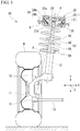
Fig. 1 is a cross-sectional view, in a left/right direction of a vehicle, of a main part of a strut suspension device including a strut mount according to an embodiment of the present invention. -
Fig. 2 is a plan view of the strut mount shown inFig. 1 . -
Fig. 3 is a cross-sectional view along a line III-III of the strut mount shown inFig. 2 . -
Fig. 4 is a cross-sectional view along a line IV-IV of the strut mount shown inFig. 2 . -
Fig. 5 is a cross-sectional view along a line V-V of the strut mount shown inFig. 2 . - Hereinafter, an embodiment of a strut mount according to the present invention will be described based on an example applied to a
strut suspension device 10 with reference toFigs. 1 to 5 . In addition, thestrut suspension device 10 is provided in a vehicle (not shown). In the description below, in thestrut suspension device 10, the installation side of astrut mount 1 to be described later is referred to as the upper side and the installation side of alower arm 14 to be described later is referred to as the lower side. - The
strut suspension device 10 includes ahub 11 which rotatably supports a vehicle wheel (front wheel) W, aknuckle 12 which protrudes from thehub 11 toward inside in the left/right direction X of the vehicle (toward the center of the vehicle in the left/right direction X of the vehicle), ashock absorber 13 which is provided on theknuckle 12 to stand upward, thestrut mount 1 to which an upper end portion of arod 16 of theshock absorber 13 is attached, alower arm 14 which is located below a lower end portion of the shock absorber 13 and extends from theknuckle 12 toward inside in the left/right direction X of the vehicle, aball joint 15 which connects thelower arm 14 and theknuckle 12, and aspring 18 which supports therod 16 and thestrut mount 1 integrally such that they are movable downward while being biased upward and also includes a tie rod and a braking device (not shown) and the like. - The
shock absorber 13 extends inward in the left/right direction X of the vehicle and upward and includes arod 16 and acylinder 19. Therod 16 and thecylinder 19 are arranged coaxially with a common axis. Hereinafter, this common axis is referred to as a center axis O, a direction intersecting the center axis O when viewed from the axial direction along the center axis O is referred to as a radial direction, and a direction around the center axis O when viewed from the axial direction is referred to as a circumferential direction. - The
rod 16 protrudes upward from thecylinder 19. A male thread portion is formed at an upper end portion of therod 16. A lower end portion of thecylinder 19 is located inside in the left/right direction X of the vehicle (the side close to the center of the vehicle in the left/right direction X of the vehicle) in relation to theball joint 15. The lower end portion of thecylinder 19 is located above theball joint 15. The lower end portion of thecylinder 19 is fixed to theknuckle 12. Alower receiving plate 29 which supports a lower end portion of thespring 18 is attached to an outer peripheral surface of thecylinder 19. - The
strut mount 1 includes an annularinner member 21 into which the upper end portion of therod 16 of theshock absorber 13 is inserted and fixed, anouter member 22 that is attached to a vehicle body B to surround theinner member 21 in the circumferential direction, and abody rubber 23 which is disposed between theinner member 21 and theouter member 22 and supports theinner member 21 and theouter member 22 such that theinner member 21 andouter member 22 are elastically shiftable relative to each other. - A
nut 25 is threaded to a portion of the upper end portion of therod 16 protruding upward from theinner member 21, and the upper end portion of therod 16 is fixed to theinner member 21. Theinner member 21 is disposed coaxially with the center axis O. - The
outer member 22 includes aninner cylinder portion 26 which surrounds theinner member 21 from outside thereof in the radial direction, and anouter cylinder portion 24 into which theinner cylinder portion 26 is fitted. Theinner cylinder portion 26 and theouter cylinder portion 24 are arranged coaxially with the center axis O. - As shown in
Figs. 3 to 5 , in theinner cylinder portion 26, the inner and outer diameters of anupper portion 26a are larger than the inner and outer diameters of alower portion 26b. - As shown in
Fig. 1 , theouter cylinder portion 24 is divided in the axial direction. That is, theouter cylinder portion 24 includes anupper portion 24a and alower portion 24b, and thelower portion 24b is provided at a position closer to theknuckle 12 than theupper portion 24a. Theupper portion 26a of theinner cylinder portion 26 is fitted into theupper portion 24a of theouter cylinder portion 24, and thelower portion 26b of theinner cylinder portion 26 is fitted into thelower portion 24b of theouter cylinder portion 24. A lower end portion of theupper portion 24a of theouter cylinder portion 24 is provided with a flange portion which protrudes outward in the radial direction and is disposed on the upper surface of the vehicle body B. An upper end portion of thelower portion 24b of theouter cylinder portion 24 is fitted to an attachment hole formed in the vehicle body B. - The
body rubber 23 connects an inner peripheral surface of theinner cylinder portion 26 and an outer peripheral surface of theinner member 21. Thebody rubber 23 is formed in an annular shape and is disposed coaxially with the center axis O. As shown inFigs. 2 to 5 , stopperrubbers 30 which protrude outward in the axial direction are disposed on thebody rubber 23. Thestopper rubbers 30 are integrally formed with thebody rubber 23. An elastic center of thebody rubber 23 is located on the center axis O. - As shown in
Fig. 1 , theouter member 22 includes a pair of supportingportions 22a which cover thebody rubber 23 from both sides in the axial direction. The supportingportions 22a cover thestopper rubbers 30 from outside thereof in the axial direction. In the example shown in the drawings, the supportingportions 22a are respectively disposed at an upper end portion of theupper portion 24a of theouter cylinder portion 24 and a lower end portion of thelower portion 24b of theouter cylinder portion 24. The pair of supportingportions 22a cover an outer peripheral edge portion of theinner member 21 from both sides in the axial direction. The pair of supportingportions 22a are formed in annular shapes and are disposed coaxially with the center axis O. A lower surface of the supportingportion 22a, which is located at the lower side, of the pair of supportingportions 22a supports an upper end portion of thespring 18. - Here, a tie rod (not shown) is connected to an end portion of the
knuckle 12 in the forward/rearward direction Z of the vehicle. At the time of steering, the tie rod pushes the end portion of theknuckle 12 in the forward/rearward direction Z of the vehicle outward in the left/right direction X of the vehicle or pulls the end portion inward in the left/right direction X of the vehicle, and theknuckle 12 and the vehicle wheel W integrally rotate around a kingpin axis K connecting the center of theball joint 15 and a connection portion P which connects therod 16 and theinner member 21. The connection portion P serves as, for example, the elastic center of thebody rubber 23. - The kingpin axis K extends outward in the left/right direction X of the vehicle and downward from above. When viewed from the forward/rearward direction Z of the vehicle, the tilt angle of the kingpin axis K with respect to the upward/downward direction Y becomes larger than the tilt angle of the center axis O with respect to the upward/downward direction Y. Accordingly, at the time of steering, the
shock absorber 13 rotates around the connection portion P between therod 16 and theinner member 21 in the forward/rearward direction Z of the vehicle with respect to theouter member 22. - The stopper rubbers 30 are disposed on both sides of the center axis O in the forward/rearward direction Z of the vehicle when viewed from the left/right direction X of the vehicle.
- Then, when the
shock absorber 13 rotates around the connection portion P between therod 16 and theinner member 21 and rotates in the forward/rearward direction Z of the vehicle with respect to theouter member 22 following the steering, the stopper rubbers 30 abut the supportingportions 22a of theouter member 22 to be compressed and deformed and generate a reaction force applied to therod 16 around the connection portion P. - The stopper rubbers 30 protrude from both sides of the
inner member 21 in the axial direction and respectively face the pair of supportingportions 22a in the axial direction. As shown inFigs. 3 to 5 , the sizes of the stopper rubbers 30 disposed on the upper and lower surfaces of theinner member 21 are set to be substantially equal to each other and the shapes thereof are substantially symmetric to each other in the upward/downward direction. In the example shown in the drawings, the sizes of the stopper rubbers 30 disposed on the upper surface of theinner member 21 are slightly larger than the sizes of the stopper rubbers 30 disposed on the lower surface of theinner member 21. The stopper rubbers 30 abut the supportingportions 22a. - As shown in
Fig. 2 , a coveringrubber 39 is disposed in each of the portions, on the outer peripheral edge portion of theinner member 21, located on both sides of the center axis O in the left/right direction X of the vehicle. The covering rubbers 39 are disposed on the upper and lower surfaces of the outer peripheral edge portion of theinner member 21. The coveringrubber 39 is integrally formed with thebody rubber 23. An axial gap is formed between the coveringrubber 39 and the supportingportion 22a. The volume of the coveringrubber 39 is smaller than the volume of the stopper rubbers 30. - Then, a reaction force applied to the
rod 16 when theshock absorber 13 rotates around the connection portion P in the forward/rearward direction Z of the vehicle with respect to theouter member 22 is larger than a reaction force applied to therod 16 when theshock absorber 13 rotates around the connection portion P in the left/right direction X of the vehicle with respect to theouter member 22. - The reaction force around the connection portion P generated in the
rod 16 and the sliding resistance of therod 16 in the axial direction with respect to thecylinder 19 gradually increase as the rotational movement amount of theshock absorber 13 around the connection portion P with respect to theouter member 22 in the forward/rearward direction Z of the vehicle increases. The relationship between the rotational movement amount and the sliding resistance can be adjusted by designing the size, material, and the like of the stopper rubbers 30 according to the characteristics of theshock absorber 13. - Further, in this embodiment, the
stopper rubber 30 includes apedestal protrusion portion 31 andtip protrusion portions 32. - As shown in
Fig. 3 , thepedestal protrusion portions 31 protrude outward in the axial direction from theinner member 21. Thepedestal protrusion portions 31 are located in the outer peripheral edge portion of theinner member 21 and are connected to the inner peripheral edge portion of thebody rubber 23. Twopedestal protrusion portions 31 extend in the circumferential direction and are arranged over an angle range of about 90° about the center axis O. The twopedestal protrusion portions 31 are arranged at positions separated from each other by about 180° about the center axis O. In this embodiment, the twopedestal protrusion portions 31 are provided on the upper and lower sides of theinner member 21. - The height of the
pedestal protrusion portions 31 in the axial direction is equal to the thickness of thepedestal protrusion portions 31 in the radial direction. The length of thepedestal protrusion portions 31 in the circumferential direction is larger than the height and the thickness of thepedestal protrusion portions 31. - The
pedestal protrusion portion 31 includes aninner surface 35 which is located at the inner end portion of thepedestal protrusion portion 31 in the radial direction and extends outward in the axial direction from theinner member 21, and includes anouter surface 36 which extends inward in the axial direction (toward theinner member 21 in the axial direction) and outward in the radial direction from the axial outer end portion of theinner surface 35. Thepedestal protrusion portion 31 tapers outward in the axial direction. In other words, an angle formed by theinner surface 35 and theouter surface 36 of thepedestal protrusion portion 31 is an acute angle. The gap between theinner surface 35 and theouter surface 36 of thepedestal protrusion portion 31 in the radial direction gradually decreases outward in the axial direction. - In the example shown in the drawings, the
inner surface 35 extends outward in the radial direction and outward in the axial direction from theinner member 21. Additionally, theinner surface 35 may extend straightly in the axial direction from theinner member 21 or may extend inward in the radial direction and outward in the axial direction from theinner member 21. - In the longitudinal sectional view in the axial direction shown in
Fig. 3 , the lengths of theinner surface 35 and theouter surface 36 are equal to each other. A tilt angle θ1 of theouter surface 36 with respect to the horizontal line L1 orthogonal to the center axis O becomes less than a tilt angle θ2 of theinner surface 35 with respect to the horizontal line L1. - An outer end portion of the
inner surface 35 in the axial direction and an inner end portion of theouter surface 36 in the radial direction are connected to each other through atop portion 31a of thepedestal protrusion portion 31 which tapers outward in the axial direction. Thetop portion 31a is formed in a curved surface shape protruding outward in the axial direction. Thetop portion 31a faces inward in the radial direction. That is, in the longitudinal sectional view shown inFig. 3 , a bisector L2 of an angle of thetop portion 31a is tilted inward in the radial direction with respect to the axial direction. - As shown in
Figs. 2 and4 , the intermediate portion of thepedestal protrusion portion 31 in the circumferential direction is provided with arecess portion 33 which is depressed inward in the axial direction and penetrates the intermediate portion in the radial direction. Therecess portion 33 is formed at the intermediate part of thepedestal protrusion portion 31 in the circumferential direction. The circumferential size of therecess portion 33 is about a half of the circumferential size of each of the portions of thepedestal protrusion portion 31 located on both sides of therecess portion 33 in the circumferential direction. A bottom surface of therecess portion 33 includes aninclined portion 33a which is located at the inner end portion of the bottom surface of therecess portion 33 in the radial direction and extends outward in the axial direction and inward in the radial direction and aflat portion 33b which extends outward in the radial direction and extends in a direction orthogonal to the axial direction from theinclined portion 33a. Both side surfaces 33c of therecess portion 33 are inclined in the axial direction to be gradually spaced from each other in the circumferential direction as the side surfaces 33c extend inward in the radial direction. - The plurality of
tip protrusion portions 32 are provided at intervals in the circumferential direction. The elasticity of thetip protrusion portion 32 in the axial direction is lower than that of thepedestal protrusion portion 31. That is, the elastic modulus of thetip protrusion portion 32 in the axial direction is smaller than the elastic modulus of thepedestal protrusion portion 31 in the axial direction. In the example shown in the drawings, thetip protrusion portion 32 and thepedestal protrusion portion 31 are integrally formed of the same material and thetip protrusion portion 32 is more easily deformed in the axial direction than thepedestal protrusion portion 31 due to a shape and a size. - In the example shown in the drawings, the
tip protrusion portion 32 is formed in a conical or a pyramidal shape that tapers outward in the axial direction and the height of thetip protrusion portion 32 and the outer diameter of the bottom portion of thetip protrusion portion 32 are equal to each other. The volume of thetip protrusion portion 32 is smaller than the volume of thepedestal protrusion portion 31. In other words, an angle formed between an outer radial surface and an inner radial surface of thetip protrusion portion 32 is an acute angle. The radial gap between the outer radial surface and the inner radial surface of the tip protrusion portion 32 (a radial width of the tip protrusion portion 32) gradually decreases outward in the axial direction. Further, in this embodiment, the angle formed between two surfaces facing the circumferential direction in thetip protrusion portion 32 is an acute angle. The circumferential gap between two surfaces of thetip protrusion portion 32 facing each other in the circumferential direction (the circumferential width of the tip protrusion portion 32) gradually decreases outward in the axial direction. Additionally, only one of the radial width of thetip protrusion portion 32 and the circumferential width of thetip protrusion portion 32 may gradually decrease outward in the axial direction. - The
tip protrusion portion 32 is disposed on theouter surface 36 of thepedestal protrusion portion 31. Thetip protrusion portion 32 is disposed at each of both end portions of thepedestal protrusion portion 31 in the circumferential direction. Twotip protrusion portions 32 are provided in onepedestal protrusion portion 31. A surface of the surfaces of thetip protrusion portion 32 facing outside in the circumferential direction (a surface of onetip protrusion portion 32 on the side away from the othertip protrusion portion 32 in the circumferential direction) is flush with a circumferential end surface of thepedestal protrusion portion 31. The circumferential size of thetip protrusion portion 32 is about a half of the circumferential size of each of the portions of thepedestal protrusion portion 31 located on both sides of therecess portion 33 in the circumferential direction. - The
tip protrusion portion 32 is disposed on a portion of theouter surface 36 of thepedestal protrusion portion 31 located outside in the radial direction of the inner end portion in the radial direction. In the longitudinal sectional view shown inFig. 3 , the length of the bottom portion of thetip protrusion portion 32 is longer than a half of the length of theouter surface 36. A surface, which faces outside in the radial direction, of the surface of thetip protrusion portion 32 is continuously connected to the radial outer edge of theouter surface 36 of thepedestal protrusion portion 31 without a step. Atop portion 32a of thetip protrusion portion 32 faces outside in the radial direction. That is, in the longitudinal sectional view, a bisector L3 of the angle of thetop portion 32a is tilted outward in the radial direction with respect to the axial direction. In the longitudinal sectional view, the tilt angle of a bisector L3 of an angle of thetop portion 32a of thetip protrusion portion 32 with respect to the axial direction is less than the tilt angle of a bisector L2 of an angle of thetop portion 31a of thepedestal protrusion portion 31 with respect to the axial direction. - As described above, according to the
strut mount 1 of this embodiment, since thestopper rubber 30 includes thepedestal protrusion portion 31 and thetip protrusion portion 32 having an elasticity lower than that of thepedestal protrusion portion 31 in the axial direction, the vibration is absorbed, when the vibration is input, by allowing the elasticity of thestopper rubber 30 to be low until the supportingportion 22a comes into contact with thepedestal protrusion portion 31 while theinner member 21 and theouter member 22 are shifted relative to each other in the axial direction, and, after the supportingportion 22a comes into contact with thepedestal protrusion portion 31, the shift can be suppressed by allowing the elasticity of thestopper rubber 30 to be increased. - Further, since the
pedestal protrusion portion 31 and thetip protrusion portion 32 taper outward in the axial direction, the elasticity of each of thepedestal protrusion portion 31 and thetip protrusion portion 32 can be initially low and gradually increased while being pushed in the axial direction by the supportingportion 22a. Thus, it is possible to suppress the elasticity of thestopper rubber 30 from being suddenly increased and suppress an impact force or abnormal noise when the supportingportion 22a contacting thetip protrusion portion 32 abuts against thepedestal protrusion portion 31 while thestopper rubber 30 is pushed in the axial direction by the supportingportion 22a. - Further, since the
stopper rubber 30 includes thetip protrusion portion 32 which protrudes outward in the axial direction from thepedestal protrusion portion 31 and abuts against the supportingportion 22a, it is possible to suppress the difference of the relative position of theinner member 21 and theouter member 22 in the axial direction by allowing thetip protrusion portion 32 to abut against the supportingportion 22a when manufacturing thestrut mount 1 and easily and reliably ensure an axial gap between thepedestal protrusion portion 31 and the supportingportion 22a as designed. - Further, the
tip protrusion portion 32 is disposed on theouter surface 36 of thepedestal protrusion portion 31 and theouter surface 36 extends inward in the axial direction and outward in the radial direction from the axial outer end portion of theinner surface 35 of thepedestal protrusion portion 31. Thus, thetop portion 32a of thetip protrusion portion 32 which tapers outward in the axial direction faces outward in the radial direction and when thetip protrusion portion 32 is pushed by the supportingportion 22a in the axial direction, thetip protrusion portion 32 is deformed outward in the radial direction to follow the deformation of thebody rubber 23. Accordingly, the elasticity of thestopper rubber 30 can be reliably maintained in a low state until the supportingportion 22a abuts against thepedestal protrusion portion 31 while theinner member 21 and theouter member 22 are shifted relative to each other in the axial direction due to the input of vibration. - Further, the
pedestal protrusion portion 31 includes theinner surface 35 and theouter surface 36 and the tilt angle θ1 of theouter surface 36 with respect to the horizontal line L1 is less than the tilt angle θ2 of theinner surface 35. Thus, thetop portion 31a of thepedestal protrusion portion 31 which tapers outward in the axial direction faces inward in the radial direction and when theinner member 21 and theouter member 22 are shifted relative to each other in the prying direction such that their center axes are tilted relative to each other, thetop portion 31a of thepedestal protrusion portion 31 can be made not to be easily in pressure contact with the supportingportion 22a. Accordingly, it is possible to suppress the elasticity of thestopper rubber 30 from being increased and suppress an impact force or abnormal noise. - Further, since the
top portion 31a of thepedestal protrusion portion 31 faces inward in the radial direction, thepedestal protrusion portion 31 can be deformed inward in the radial direction when thepedestal protrusion portion 31 is pushed in the axial direction by the supportingportion 22a. Thus, since it is possible to suppress thepedestal protrusion portion 31 from being deformed due to the deformation of thebody rubber 23 when theinner member 21 and theouter member 22 are largely shifted relative to each other in the axial direction, the elasticity of thestopper rubber 30 can be increased and the further shift in the axial direction can be suppressed. - Further, since the
tip protrusion portion 32 is disposed at each of both end portions of thepedestal protrusion portion 31 in the circumferential direction, it is possible to ensure a long circumferential distance between thetip protrusion portions 32 adjacent to each other in the circumferential direction and easily realize that the plurality oftip protrusion portions 32 abut against the supportingportion 22a with an equal force. - Further, since the
recess portion 33 is formed at the intermediate portion of thepedestal protrusion portion 31 in the circumferential direction, while thestopper rubber 30 is pushed by the supportingportion 22a in the axial direction, it is possible to easily adjust the magnitude of the elasticity of thestopper rubber 30 after the supportingportion 22a abuts against thepedestal protrusion portion 31. - Further, since the
tip protrusion portion 32 is disposed on a portion of theouter surface 36 of thepedestal protrusion portion 31 located outside in the radial direction of the inner end portion in the radial direction of theouter surface 36, it is possible to ensure a long circumferential distance between thetip protrusion portions 32 adjacent to each other in the circumferential direction and easily realize that the plurality oftip protrusion portions 32 abut against the supportingportion 22a with an equal force. - Additionally, the technical scope of the present invention is not limited to the above-described embodiment and can be modified into various forms in the scope not departing from the scope of the present invention.
- For example, in the above-described embodiment, a configuration in which the stopper rubbers 30 are disposed on both sides of the center axis O in the forward/rearward direction Z of the vehicle when viewed from the left and right direction X of the vehicle has been described, but the arrangement positions of the stopper rubbers 30 may be changed as appropriate.
- Further, in the above-described embodiment, the sizes of the stopper rubbers 30 disposed on the upper and lower surfaces of the
inner member 21 are set to be substantially equal to each other and the shapes thereof are substantially symmetric to each other in the upward/downward direction. However, thesestopper rubbers 30 may have different sizes and shapes. - Further, the
stopper rubber 30 may adopt a configuration in which the stopper rubber continuously extends over the entire circumference without therecess portion 33. - Further, the covering
rubber 39 is disposed at each of the portions of theinner member 21 on both sides of the center axis O in the left/right direction X of the vehicle, but the coveringrubber 39 may not be provided. - Further, the
tip protrusion portion 32 may be disposed on the intermediate portion of thepedestal protrusion portion 31 in the circumferential direction. - In addition, the constituent elements in the above-described embodiment can be appropriately replaced with well-known constituent elements without departing from the scope of the present invention and the above-described modified examples may be appropriately combined.
- In the above-described aspect of the present invention, since the stopper rubber (30) includes a pedestal protrusion portion (31) and a tip protrusion portion (32) having an elasticity lower than that of the pedestal protrusion portion in the axial direction, the vibration is absorbed, when the vibration is input, by allowing the elasticity of the stopper rubber to be low until the supporting portion (22a) comes into contact with the pedestal protrusion portion while the inner member (21) and the outer member (22) are shifted relative to each other in the axial direction, and, after the supporting portion comes into contact with the pedestal protrusion portion, the shift can be suppressed by allowing the elasticity of the stopper rubber to be increased.
- Further, since the pedestal protrusion portion and the tip protrusion portion taper outward in the axial direction, the elasticity of each of the pedestal protrusion portion and the tip protrusion portion can be initially low and gradually increased while being pushed in the axial direction by the supporting portion. Thus, it is possible to suppress the elasticity of the stopper rubber from being suddenly increased and suppress an impact force or abnormal noise when the supporting portion contacting the tip protrusion portion abuts against the pedestal protrusion portion while the stopper rubber is pushed in the axial direction by the supporting portion.
- Further, since the stopper rubber includes the tip protrusion portion which protrudes outward in the axial direction from the pedestal protrusion portion and abuts against the supporting portion, it is possible to suppress the difference of the relative position of the inner member and the outer member in the axial direction by allowing the tip protrusion portion to abut against the supporting portion when manufacturing the strut mount (1) and easily and reliably ensure an axial gap between the pedestal protrusion portion and the supporting portion as designed.
- Further, the tip protrusion portion is disposed on the outer surface (36) of the pedestal protrusion portion and the outer surface extends inward in the axial direction and outward in the radial direction from the axial outer end portion of the inner surface (35) of the pedestal protrusion portion. Thus, the top portion of the tip protrusion portion which tapers outward in the axial direction faces outward in the radial direction and when the tip protrusion portion is pushed by the supporting portion in the axial direction, the tip protrusion portion can be deformed outward in the radial direction to follow the deformation of the body rubber (23). Accordingly, the elasticity of the stopper rubber can be reliably maintained in a low state until the supporting portion abuts against the pedestal protrusion portion while the inner member and the outer member are shifted relative to each other in the axial direction due to the input of vibration.
- Further, the pedestal protrusion portion includes the inner surface and the outer surface and the tilt angle of the outer surface with respect to the horizontal line is less than the tilt angle of the inner surface. Thus, the top portion of the pedestal protrusion portion which tapers outward in the axial direction faces inward in the radial direction and when the inner member and the outer member are shifted relative to each other in the prying direction such that their center axes are tilted relative to each other, the top portion of the pedestal protrusion portion can be made not to be easily in pressure contact with the supporting portion. Accordingly, it is possible to suppress the elasticity of the stopper rubber from being increased and suppress an impact force or abnormal noise.
- Further, since the top portion of the pedestal protrusion portion faces inward in the radial direction, the pedestal protrusion portion can be deformed inward in the radial direction when the pedestal protrusion portion is pushed in the axial direction by the supporting portion. Thus, since it is possible to suppress the pedestal protrusion portion from being deformed due to the deformation of the body rubber when the inner member and the outer member are largely shifted relative to each other in the axial direction, the elasticity of the stopper rubber can be increased and the further shift in the axial direction can be suppressed.
- Here, in the above-described aspect, the pedestal protrusion portion may extend in the circumferential direction and the tip protrusion portion may be disposed at each of both end portions of the pedestal protrusion portion in the circumferential direction.
- In this case, since the tip protrusion portion is disposed at each of both end portions of the pedestal protrusion portion in the circumferential direction, it is possible to ensure a long circumferential distance between the tip protrusion portions adjacent to each other in the circumferential direction and easily realize that the plurality of tip protrusion portions abut against the supporting portion with an equal force.
- Further, in the above-described aspect, the pedestal protrusion portion may extend in the circumferential direction and an intermediate portion of the pedestal protrusion portion in the circumferential direction may be provided with a recess portion (33) which is depressed inward in the axial direction and penetrates the intermediate portion in the radial direction.
- In this case, since the recess portion is formed at the intermediate portion of the pedestal protrusion portion in the circumferential direction, while the stopper rubber is pushed by the supporting portion in the axial direction, it is possible to easily adjust the magnitude of the elasticity of the stopper rubber after the supporting portion abuts against the pedestal protrusion portion.
- Further, in the above-described aspect, a plurality of the tip protrusion portions may be arranged at intervals in the circumferential direction and may be arranged on portions of the outer surface located outside of inner end portion in the radial direction of the outer surface.
- In this case, since the tip protrusion portion is disposed on the portion of the outer surface of the pedestal protrusion portion located outside in the radial direction of the inner end portion in the radial direction of the outer surface , it is possible to ensure a long circumferential distance between the tip protrusion portions adjacent to each other in the circumferential direction and easily realize that the plurality of tip protrusion portions abut against the supporting portion with an equal force.
- According to the above-described aspect of the present invention, it is possible to suppress an impact force or abnormal noise generated when vibration in each of the axial direction and the prying direction is input.
- The present invention can be used for a strut mount including an inner member, an outer member surrounding the inner member, and a body rubber supporting the inner member and the outer member to be elastically shiftable relative to each other.
-
- 1
- Strut mount
- 13
- Shock absorber
- 16
- Rod
- 21
- Inner member
- 22
- Outer member
- 22a
- Supporting portion
- 23
- Body rubber
- 30
- Stopper rubber
- 31
- Pedestal protrusion portion
- 32
- Tip protrusion portion
- 33
- Recess portion
- 35
- Inner side surface
- 36
- Outer side surface
- B
- Vehicle body
- L1
- Horizontal line
- O
- Center axis
- θ1
- Tilt angle of outer surface
- θ2
- Tilt angle of inner surface
Claims (4)
- A strut mount comprising:an annular inner member into which an upper end portion of a rod of a shock absorber is inserted and fixed;an outer member that surrounds the inner member in a circumferential direction around a center axis of the inner member and is attached to a vehicle body, anda body rubber which is disposed between the inner member and the outer member and supports the inner member and the outer member such that the inner and outer members are elastically shiftable relative to each other,wherein a stopper rubber which protrudes outward in an axial direction along the center axis is disposed on the body rubber,wherein the outer member includes a supporting portion which covers the stopper rubber from outside thereof in the axial direction,wherein the stopper rubber includesa pedestal protrusion portion which protrudes outward in the axial direction from the inner member anda tip protrusion portion which protrudes outward in the axial direction from the pedestal protrusion portion, contacts the supporting portion, and has an elasticity in the axial direction lower than that of the pedestal protrusion portion,wherein the pedestal protrusion portion and the tip protrusion portion taper outward in the axial direction,wherein the pedestal protrusion portion includesan inner surface which is located at an inner end portion in a radial direction of the pedestal protrusion portion and extends outward in the axial direction from the inner member, andan outer surface which extends inward in the axial direction and outward in the radial direction from an outer end portion in the axial direction of the inner surface,wherein a tilt angle of the outer surface with respect to a horizontal line orthogonal to the center axis is less than a tilt angle of the inner surface with respect to the horizontal line, andwherein the tip protrusion portion is disposed on the outer surface.
- The strut mount according to claim 1,wherein the pedestal protrusion portion extends in the circumferential direction, andwherein the tip protrusion portion is disposed at each of both end portions of the pedestal protrusion portion in the circumferential direction.
- The strut mount according to claim 1 or 2,wherein the pedestal protrusion portion extends in the circumferential direction, andwherein an intermediate portion in the circumferential direction of the pedestal protrusion portion is provided with a recess portion which is depressed inward in the axial direction and penetrates the intermediate portion in the radial direction.
- The strut mount according to any one of claims 1 to 3, wherein a plurality of the tip protrusion portions are provided at intervals in the circumferential direction and are disposed on portions of the outer surface located outside in the radial direction of an inner end portion in the radial direction of the outer surface.
Applications Claiming Priority (2)
| Application Number | Priority Date | Filing Date | Title |
|---|---|---|---|
| JP2018227632A JP7140661B2 (en) | 2018-12-04 | 2018-12-04 | strut mount |
| PCT/JP2019/047306 WO2020116483A1 (en) | 2018-12-04 | 2019-12-04 | Strut mount |
Publications (2)
| Publication Number | Publication Date |
|---|---|
| EP3892480A1 true EP3892480A1 (en) | 2021-10-13 |
| EP3892480A4 EP3892480A4 (en) | 2022-09-07 |
Family
ID=70973628
Family Applications (1)
| Application Number | Title | Priority Date | Filing Date |
|---|---|---|---|
| EP19891828.6A Pending EP3892480A4 (en) | 2018-12-04 | 2019-12-04 | STRUT SUPPORT |
Country Status (5)
| Country | Link |
|---|---|
| US (1) | US11548341B2 (en) |
| EP (1) | EP3892480A4 (en) |
| JP (1) | JP7140661B2 (en) |
| CN (1) | CN113286714B (en) |
| WO (1) | WO2020116483A1 (en) |
Cited By (1)
| Publication number | Priority date | Publication date | Assignee | Title |
|---|---|---|---|---|
| DE102023107866A1 (en) | 2023-03-28 | 2024-10-02 | Sumitomo Riko Company Limited | camp |
Families Citing this family (2)
| Publication number | Priority date | Publication date | Assignee | Title |
|---|---|---|---|---|
| JP2024051426A (en) * | 2022-09-30 | 2024-04-11 | 住友理工株式会社 | Cylindrical vibration isolation device |
| DE102023114914A1 (en) * | 2023-06-07 | 2024-12-12 | Vibracoustic Se | Elastic bearing with linear behavior |
Family Cites Families (19)
| Publication number | Priority date | Publication date | Assignee | Title |
|---|---|---|---|---|
| US4290626A (en) * | 1980-04-25 | 1981-09-22 | General Motors Corporation | Dual function strut bearing |
| JPS5865342A (en) * | 1981-10-09 | 1983-04-19 | Nissan Motor Co Ltd | Elastically supporting construction |
| JPS5877945A (en) * | 1981-10-31 | 1983-05-11 | Toyota Motor Corp | Upper support for suspension device |
| US4486028A (en) * | 1982-12-22 | 1984-12-04 | Toyota Jidosha Kabushiki Kaisha | Upper support structure for front wheel suspension of automobile |
| JPH0511046Y2 (en) * | 1985-03-01 | 1993-03-18 | ||
| JP3334436B2 (en) * | 1995-06-30 | 2002-10-15 | 東海ゴム工業株式会社 | Strut mount |
| GB2347905A (en) * | 1999-03-19 | 2000-09-20 | Draftex Ind Ltd | A suspension arrangement having a bearing race incorporated within a resilient support element |
| DE20100723U1 (en) * | 2001-01-16 | 2001-04-05 | PAGUAG GmbH, 40472 Düsseldorf | Shock absorber bearing |
| JP3994769B2 (en) * | 2002-03-22 | 2007-10-24 | 東海ゴム工業株式会社 | Suspension upper mount |
| JP4138715B2 (en) * | 2004-08-23 | 2008-08-27 | 本田技研工業株式会社 | Damper mounting structure |
| JP2006264425A (en) * | 2005-03-23 | 2006-10-05 | Tokai Rubber Ind Ltd | Upper support for suspension and automobile suspension system using the same |
| JP4005607B2 (en) | 2005-03-31 | 2007-11-07 | 東洋ゴム工業株式会社 | Strut mount |
| JP4303277B2 (en) * | 2006-10-19 | 2009-07-29 | 東洋ゴム工業株式会社 | Vibration isolator |
| US8574394B2 (en) | 2007-12-21 | 2013-11-05 | Henkel Ag & Co. Kgaa | Method for preparing a moisture curable hot melt adhesive |
| DE102009027319A1 (en) * | 2009-06-30 | 2011-01-05 | Ford Global Technologies, LLC, Dearborn | Elastic bush |
| CN103109105B (en) * | 2010-09-14 | 2015-08-12 | 本田技研工业株式会社 | Vibration damper mounting construction |
| JP5695468B2 (en) | 2011-03-30 | 2015-04-08 | 東洋ゴム工業株式会社 | Strut mount |
| JP5387606B2 (en) * | 2011-04-04 | 2014-01-15 | マツダ株式会社 | Vehicle suspension structure |
| KR102756530B1 (en) * | 2020-08-25 | 2025-01-20 | 현대모비스 주식회사 | Rotation induction device for vehicle |
-
2018
- 2018-12-04 JP JP2018227632A patent/JP7140661B2/en active Active
-
2019
- 2019-12-04 EP EP19891828.6A patent/EP3892480A4/en active Pending
- 2019-12-04 WO PCT/JP2019/047306 patent/WO2020116483A1/en not_active Ceased
- 2019-12-04 CN CN201980079043.4A patent/CN113286714B/en active Active
- 2019-12-04 US US17/292,198 patent/US11548341B2/en active Active
Cited By (1)
| Publication number | Priority date | Publication date | Assignee | Title |
|---|---|---|---|---|
| DE102023107866A1 (en) | 2023-03-28 | 2024-10-02 | Sumitomo Riko Company Limited | camp |
Also Published As
| Publication number | Publication date |
|---|---|
| US11548341B2 (en) | 2023-01-10 |
| CN113286714A (en) | 2021-08-20 |
| WO2020116483A1 (en) | 2020-06-11 |
| CN113286714B (en) | 2024-04-26 |
| JP7140661B2 (en) | 2022-09-21 |
| EP3892480A4 (en) | 2022-09-07 |
| US20210387493A1 (en) | 2021-12-16 |
| JP2020090981A (en) | 2020-06-11 |
Similar Documents
| Publication | Publication Date | Title |
|---|---|---|
| US8985604B2 (en) | Cross axis joint with elastomeric isolation | |
| US11548341B2 (en) | Strut mount | |
| US8061693B2 (en) | Elastic bushing | |
| KR102072142B1 (en) | Bush for stabilizer, fastening tool, and fastening method | |
| US11433725B2 (en) | Bushing and vehicle suspension device | |
| CN101445027B (en) | Lower spring seat mounting structure for vehicle suspension | |
| US11358427B2 (en) | Suspension for vehicle | |
| US10471789B2 (en) | Suspension device | |
| EP2143972B1 (en) | Bump stopper | |
| US10661627B2 (en) | Bracket | |
| JP5504132B2 (en) | Snap-in valve and tire valve unit | |
| JP2013228037A (en) | Ball joint | |
| US20160046165A1 (en) | Suspension coil spring and strut type suspension | |
| JP2014073843A (en) | Snap-in valve and tire valve unit | |
| WO2018096814A1 (en) | Bump stopper | |
| WO2020116484A1 (en) | Strut-type suspension device | |
| WO2017208392A1 (en) | Tire valve and tire valve mounting structure | |
| JP7044469B2 (en) | Anti-vibration device | |
| JP7122222B2 (en) | Damper mount mounting structure | |
| JP6943424B2 (en) | Ball joint | |
| JP2002021931A (en) | Member mount | |
| JP6546716B2 (en) | Strut mount | |
| JP7267593B2 (en) | Ball joint and its dust cover | |
| JP2008213728A (en) | Stabilizer bush | |
| JP2008151177A (en) | Strut mount |
Legal Events
| Date | Code | Title | Description |
|---|---|---|---|
| STAA | Information on the status of an ep patent application or granted ep patent |
Free format text: STATUS: THE INTERNATIONAL PUBLICATION HAS BEEN MADE |
|
| PUAI | Public reference made under article 153(3) epc to a published international application that has entered the european phase |
Free format text: ORIGINAL CODE: 0009012 |
|
| STAA | Information on the status of an ep patent application or granted ep patent |
Free format text: STATUS: REQUEST FOR EXAMINATION WAS MADE |
|
| 17P | Request for examination filed |
Effective date: 20210511 |
|
| AK | Designated contracting states |
Kind code of ref document: A1 Designated state(s): AL AT BE BG CH CY CZ DE DK EE ES FI FR GB GR HR HU IE IS IT LI LT LU LV MC MK MT NL NO PL PT RO RS SE SI SK SM TR |
|
| DAV | Request for validation of the european patent (deleted) | ||
| DAX | Request for extension of the european patent (deleted) | ||
| REG | Reference to a national code |
Ref country code: DE Ref legal event code: R079 Free format text: PREVIOUS MAIN CLASS: B60G0011160000 Ipc: B60G0011520000 |
|
| RAP1 | Party data changed (applicant data changed or rights of an application transferred) |
Owner name: PROSPIRA CORPORATION |
|
| A4 | Supplementary search report drawn up and despatched |
Effective date: 20220804 |
|
| RIC1 | Information provided on ipc code assigned before grant |
Ipc: F16F 1/38 20060101ALI20220729BHEP Ipc: F16F 9/54 20060101ALI20220729BHEP Ipc: B60G 15/06 20060101ALI20220729BHEP Ipc: B60G 11/52 20060101AFI20220729BHEP |
|
| STAA | Information on the status of an ep patent application or granted ep patent |
Free format text: STATUS: EXAMINATION IS IN PROGRESS |
|
| 17Q | First examination report despatched |
Effective date: 20250922 |