EP3892075B1 - Systems comprising agricultural implements connected to lifting hitches and related control systems and methods - Google Patents
Systems comprising agricultural implements connected to lifting hitches and related control systems and methods Download PDFInfo
- Publication number
- EP3892075B1 EP3892075B1 EP21157517.0A EP21157517A EP3892075B1 EP 3892075 B1 EP3892075 B1 EP 3892075B1 EP 21157517 A EP21157517 A EP 21157517A EP 3892075 B1 EP3892075 B1 EP 3892075B1
- Authority
- EP
- European Patent Office
- Prior art keywords
- relative
- lifting hitch
- sensor
- toolbar
- implement
- Prior art date
- Legal status (The legal status is an assumption and is not a legal conclusion. Google has not performed a legal analysis and makes no representation as to the accuracy of the status listed.)
- Active
Links
- 238000000034 method Methods 0.000 title claims description 22
- 241001236644 Lavinia Species 0.000 title 1
- 230000033001 locomotion Effects 0.000 claims description 10
- 230000008859 change Effects 0.000 description 5
- 239000000463 material Substances 0.000 description 4
- 238000003860 storage Methods 0.000 description 4
- 239000002689 soil Substances 0.000 description 3
- 238000003971 tillage Methods 0.000 description 3
- 238000007792 addition Methods 0.000 description 2
- 238000012217 deletion Methods 0.000 description 2
- 230000037430 deletion Effects 0.000 description 2
- 230000001419 dependent effect Effects 0.000 description 2
- 230000007246 mechanism Effects 0.000 description 2
- 238000012986 modification Methods 0.000 description 2
- 230000004048 modification Effects 0.000 description 2
- 238000010899 nucleation Methods 0.000 description 2
- 238000012545 processing Methods 0.000 description 2
- 230000009286 beneficial effect Effects 0.000 description 1
- 238000002485 combustion reaction Methods 0.000 description 1
- 238000007796 conventional method Methods 0.000 description 1
- 238000001514 detection method Methods 0.000 description 1
- 230000006870 function Effects 0.000 description 1
- 238000003973 irrigation Methods 0.000 description 1
- 230000002262 irrigation Effects 0.000 description 1
- 238000004519 manufacturing process Methods 0.000 description 1
- 238000005259 measurement Methods 0.000 description 1
- 235000015097 nutrients Nutrition 0.000 description 1
- 230000003287 optical effect Effects 0.000 description 1
- 230000008569 process Effects 0.000 description 1
Images


Classifications
-
- A—HUMAN NECESSITIES
- A01—AGRICULTURE; FORESTRY; ANIMAL HUSBANDRY; HUNTING; TRAPPING; FISHING
- A01B—SOIL WORKING IN AGRICULTURE OR FORESTRY; PARTS, DETAILS, OR ACCESSORIES OF AGRICULTURAL MACHINES OR IMPLEMENTS, IN GENERAL
- A01B63/00—Lifting or adjusting devices or arrangements for agricultural machines or implements
- A01B63/002—Devices for adjusting or regulating the position of tools or wheels
- A01B63/008—Vertical adjustment of tools
-
- A—HUMAN NECESSITIES
- A01—AGRICULTURE; FORESTRY; ANIMAL HUSBANDRY; HUNTING; TRAPPING; FISHING
- A01B—SOIL WORKING IN AGRICULTURE OR FORESTRY; PARTS, DETAILS, OR ACCESSORIES OF AGRICULTURAL MACHINES OR IMPLEMENTS, IN GENERAL
- A01B59/00—Devices specially adapted for connection between animals or tractors and agricultural machines or implements
- A01B59/04—Devices specially adapted for connection between animals or tractors and agricultural machines or implements for machines pulled or pushed by a tractor
- A01B59/042—Devices specially adapted for connection between animals or tractors and agricultural machines or implements for machines pulled or pushed by a tractor having pulling means arranged on the rear part of the tractor
- A01B59/043—Devices specially adapted for connection between animals or tractors and agricultural machines or implements for machines pulled or pushed by a tractor having pulling means arranged on the rear part of the tractor supported at three points, e.g. by quick-release couplings
-
- A—HUMAN NECESSITIES
- A01—AGRICULTURE; FORESTRY; ANIMAL HUSBANDRY; HUNTING; TRAPPING; FISHING
- A01B—SOIL WORKING IN AGRICULTURE OR FORESTRY; PARTS, DETAILS, OR ACCESSORIES OF AGRICULTURAL MACHINES OR IMPLEMENTS, IN GENERAL
- A01B59/00—Devices specially adapted for connection between animals or tractors and agricultural machines or implements
- A01B59/06—Devices specially adapted for connection between animals or tractors and agricultural machines or implements for machines mounted on tractors
- A01B59/066—Devices specially adapted for connection between animals or tractors and agricultural machines or implements for machines mounted on tractors of the type comprising at least two lower arms and one upper arm generally arranged in a triangle (e.g. three-point hitches)
-
- A—HUMAN NECESSITIES
- A01—AGRICULTURE; FORESTRY; ANIMAL HUSBANDRY; HUNTING; TRAPPING; FISHING
- A01B—SOIL WORKING IN AGRICULTURE OR FORESTRY; PARTS, DETAILS, OR ACCESSORIES OF AGRICULTURAL MACHINES OR IMPLEMENTS, IN GENERAL
- A01B63/00—Lifting or adjusting devices or arrangements for agricultural machines or implements
- A01B63/02—Lifting or adjusting devices or arrangements for agricultural machines or implements for implements mounted on tractors
- A01B63/10—Lifting or adjusting devices or arrangements for agricultural machines or implements for implements mounted on tractors operated by hydraulic or pneumatic means
- A01B63/1006—Lifting or adjusting devices or arrangements for agricultural machines or implements for implements mounted on tractors operated by hydraulic or pneumatic means the hydraulic or pneumatic means structurally belonging to the tractor
-
- A—HUMAN NECESSITIES
- A01—AGRICULTURE; FORESTRY; ANIMAL HUSBANDRY; HUNTING; TRAPPING; FISHING
- A01B—SOIL WORKING IN AGRICULTURE OR FORESTRY; PARTS, DETAILS, OR ACCESSORIES OF AGRICULTURAL MACHINES OR IMPLEMENTS, IN GENERAL
- A01B63/00—Lifting or adjusting devices or arrangements for agricultural machines or implements
- A01B63/02—Lifting or adjusting devices or arrangements for agricultural machines or implements for implements mounted on tractors
- A01B63/10—Lifting or adjusting devices or arrangements for agricultural machines or implements for implements mounted on tractors operated by hydraulic or pneumatic means
- A01B63/111—Lifting or adjusting devices or arrangements for agricultural machines or implements for implements mounted on tractors operated by hydraulic or pneumatic means regulating working depth of implements
- A01B63/1112—Lifting or adjusting devices or arrangements for agricultural machines or implements for implements mounted on tractors operated by hydraulic or pneumatic means regulating working depth of implements using a non-tactile ground distance measurement, e.g. using reflection of waves
-
- A—HUMAN NECESSITIES
- A01—AGRICULTURE; FORESTRY; ANIMAL HUSBANDRY; HUNTING; TRAPPING; FISHING
- A01B—SOIL WORKING IN AGRICULTURE OR FORESTRY; PARTS, DETAILS, OR ACCESSORIES OF AGRICULTURAL MACHINES OR IMPLEMENTS, IN GENERAL
- A01B63/00—Lifting or adjusting devices or arrangements for agricultural machines or implements
- A01B63/02—Lifting or adjusting devices or arrangements for agricultural machines or implements for implements mounted on tractors
- A01B63/10—Lifting or adjusting devices or arrangements for agricultural machines or implements for implements mounted on tractors operated by hydraulic or pneumatic means
- A01B63/111—Lifting or adjusting devices or arrangements for agricultural machines or implements for implements mounted on tractors operated by hydraulic or pneumatic means regulating working depth of implements
- A01B63/1115—Lifting or adjusting devices or arrangements for agricultural machines or implements for implements mounted on tractors operated by hydraulic or pneumatic means regulating working depth of implements using a mechanical ground contact sensor
-
- A—HUMAN NECESSITIES
- A01—AGRICULTURE; FORESTRY; ANIMAL HUSBANDRY; HUNTING; TRAPPING; FISHING
- A01B—SOIL WORKING IN AGRICULTURE OR FORESTRY; PARTS, DETAILS, OR ACCESSORIES OF AGRICULTURAL MACHINES OR IMPLEMENTS, IN GENERAL
- A01B63/00—Lifting or adjusting devices or arrangements for agricultural machines or implements
- A01B63/02—Lifting or adjusting devices or arrangements for agricultural machines or implements for implements mounted on tractors
- A01B63/10—Lifting or adjusting devices or arrangements for agricultural machines or implements for implements mounted on tractors operated by hydraulic or pneumatic means
- A01B63/118—Mounting implements on power-lift linkages
-
- A—HUMAN NECESSITIES
- A01—AGRICULTURE; FORESTRY; ANIMAL HUSBANDRY; HUNTING; TRAPPING; FISHING
- A01B—SOIL WORKING IN AGRICULTURE OR FORESTRY; PARTS, DETAILS, OR ACCESSORIES OF AGRICULTURAL MACHINES OR IMPLEMENTS, IN GENERAL
- A01B79/00—Methods for working soil
- A01B79/02—Methods for working soil combined with other agricultural processing, e.g. fertilising, planting
-
- A—HUMAN NECESSITIES
- A01—AGRICULTURE; FORESTRY; ANIMAL HUSBANDRY; HUNTING; TRAPPING; FISHING
- A01C—PLANTING; SOWING; FERTILISING
- A01C7/00—Sowing
- A01C7/20—Parts of seeders for conducting and depositing seed
- A01C7/201—Mounting of the seeding tools
- A01C7/203—Mounting of the seeding tools comprising depth regulation means
-
- A—HUMAN NECESSITIES
- A01—AGRICULTURE; FORESTRY; ANIMAL HUSBANDRY; HUNTING; TRAPPING; FISHING
- A01C—PLANTING; SOWING; FERTILISING
- A01C7/00—Sowing
- A01C7/20—Parts of seeders for conducting and depositing seed
- A01C7/208—Chassis; Coupling means to a tractor or the like; Lifting means; Side markers
-
- B—PERFORMING OPERATIONS; TRANSPORTING
- B60—VEHICLES IN GENERAL
- B60D—VEHICLE CONNECTIONS
- B60D1/00—Traction couplings; Hitches; Draw-gear; Towing devices
- B60D1/01—Traction couplings or hitches characterised by their type
- B60D1/02—Bolt or shackle-type couplings
-
- B—PERFORMING OPERATIONS; TRANSPORTING
- B60—VEHICLES IN GENERAL
- B60D—VEHICLE CONNECTIONS
- B60D1/00—Traction couplings; Hitches; Draw-gear; Towing devices
- B60D1/24—Traction couplings; Hitches; Draw-gear; Towing devices characterised by arrangements for particular functions
- B60D1/246—Traction couplings; Hitches; Draw-gear; Towing devices characterised by arrangements for particular functions for actuating the hitch by powered means
-
- B—PERFORMING OPERATIONS; TRANSPORTING
- B60—VEHICLES IN GENERAL
- B60D—VEHICLE CONNECTIONS
- B60D1/00—Traction couplings; Hitches; Draw-gear; Towing devices
- B60D1/24—Traction couplings; Hitches; Draw-gear; Towing devices characterised by arrangements for particular functions
- B60D1/42—Traction couplings; Hitches; Draw-gear; Towing devices characterised by arrangements for particular functions for being adjustable
- B60D1/46—Traction couplings; Hitches; Draw-gear; Towing devices characterised by arrangements for particular functions for being adjustable vertically
-
- G—PHYSICS
- G05—CONTROLLING; REGULATING
- G05D—SYSTEMS FOR CONTROLLING OR REGULATING NON-ELECTRIC VARIABLES
- G05D3/00—Control of position or direction
- G05D3/12—Control of position or direction using feedback
-
- A—HUMAN NECESSITIES
- A01—AGRICULTURE; FORESTRY; ANIMAL HUSBANDRY; HUNTING; TRAPPING; FISHING
- A01C—PLANTING; SOWING; FERTILISING
- A01C7/00—Sowing
- A01C7/08—Broadcast seeders; Seeders depositing seeds in rows
Definitions
- aspects of the present disclosure relate generally to machines and methods for working agricultural fields.
- aspects relate to implements (e.g., planters, tillage, etc.) and to methods of controlling such implements.
- Crop yields are affected by a variety of factors, such as seed placement, soil quality, weather, irrigation, and nutrient applications. Seeds are typically planted in trenches formed by discs or other mechanisms of a planter row unit. Depth of seed placement is important because seeds planted at different depths emerge at different times, resulting in uneven crop growth. Trench depth can be affected by soil type, moisture level, row unit speed, and operation of the opening discs. It would be beneficial to have improved methods of controlling the location of planter row units so that seeds can be more precisely placed in a field.
- US2017/359941 A1 discloses a system according to the preamble of claim 1.
- the terms “comprising,” “including,” “containing,” “characterized by,” and grammatical equivalents thereof are inclusive or open-ended terms that do not exclude additional, unrecited elements or method steps, but also include the more restrictive terms “consisting of” and “consisting essentially of” and grammatical equivalents thereof.
- the term "may” with respect to a material, structure, feature, or method act indicates that such is contemplated for use in implementation of an embodiment of the disclosure, and such term is used in preference to the more restrictive term “is” so as to avoid any implication that other, compatible materials, structures, features, and methods usable in combination therewith should or must be excluded.
- the term “configured” refers to a size, shape, material composition, and arrangement of one or more of at least one structure and at least one apparatus facilitating operation of one or more of the structure and the apparatus in a predetermined way.
- spatially relative terms such as “beneath,” “below,” “lower,” “bottom,” “above,” “upper,” “top,” “front,” “rear,” “left,” “right,” and the like, may be used for ease of description to describe one element's or feature's relationship to another element(s) or feature(s) as illustrated in the figures. Unless otherwise specified, the spatially relative terms are intended to encompass different orientations of the materials in addition to the orientation depicted in the figures.
- the term "substantially" in reference to a given parameter, property, or condition means and includes to a degree that one of ordinary skill in the art would understand that the given parameter, property, or condition is met with a degree of variance, such as within acceptable manufacturing tolerances.
- the parameter, property, or condition may be at least 90.0% met, at least 95.0% met, at least 99.0% met, or even at least 99.9% met.
- the term "about” used in reference to a given parameter is inclusive of the stated value and has the meaning dictated by the context (e.g., it includes the degree of error associated with measurement of the given parameter).
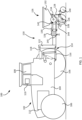
- FIG. 1 is a simplified side view of a system 100 including a tractor 102 and an implement 120.
- the tractor 102 includes a chassis 104 supported by wheels 106 and/or tracks.
- An operator cab 108 is typically supported by the chassis 104 and includes a control system 110 that may control operation of the tractor 102 and/or the implement 120.
- the operator cab 108 may be omitted if the tractor 102 is configured to function without an onboard human operator (e.g., as a remotely operated drone or a computer-operated machine).
- the control system 110 may include a central processing unit (“CPU”), memory, and graphical user interface ("GUI”) (e.g., a touch-screen interface).
- CPU central processing unit
- GUI graphical user interface
- a global positioning system (“GPS”) receiver may be mounted to the tractor 102 and connected to communicate with the control system 110.
- the tractor 102 has a power source 112 configured to move the wheels 106, which may include an internal combustion engine, an electric motor, or other source.
- the power source 112 may also provide power to a lifting hitch 114 carried by the tractor 102. Note that one of the rear wheels 106 has been omitted from view to more clearly show the lifting hitch 114.
- the lifting hitch 114 may be a 3-point hitch commonly carried by agricultural and other tractors.
- the lifting hitch 114 may be attached to the chassis 104 and include two lower lifting arms 116 to which the implement 120 may be attached.
- An additional top link 118 (depicted in FIG. 1 as a piston-type actuator) may connect the implement 120 to the tractor 102.
- the implement 120 has a frame 122 including an integrated toolbar 124 supporting row units 126. That is, the frame 122 and the toolbar 124 may form a rigid structure.
- the row units 126 may be any type of ground-engaging device for planting, seeding, fertilizing, tilling, or otherwise working crops or soil, typically in rows.
- the row unit 126 is shown in the form of a planter row unit.
- the row unit 126 has a body 128 pivotally connected to the toolbar 124 by a parallel linkage 130, enabling the row unit 126 to move vertically independent of the toolbar 124.
- the body 128 may be a unitary member, or may include one or more members coupled together (e.g., by bolts, welds, etc.).
- the body 128 operably supports one or more hoppers 132, a seed meter 134, a seed delivery mechanism 136, a seed trench opening assembly 138, a trench closing assembly 140, and any other components as known in the art.
- the row unit 126 shown in FIG. 1 may optionally be a part of a central fill planter, in which case the hoppers 132 may be one or more mini-hoppers fed by a central hopper carried by the implement 120.
- At least one sensor 142 and/or 144 is used to determine a position of a row unit 126 relative to the ground.
- the sensor(s) 142, 144 may be carried on the body 128 of the row unit 126 itself. In other embodiments, sensor(s) may be carried by the toolbar 124, the tractor 102, or even by another vehicle (e.g., another ground vehicle, an unmanned aerial vehicle, etc.).
- the sensor 142 may be a rotary sensor configured to measure an angle of an element of the parallel linkage 130 relative to the body 128 of the row unit 126 or to the toolbar 124, and may be connected to a pivot point of the body 128 of the row unit 126 or to the toolbar 124.
- an additional sensor 145 may be configured to detect the position of the toolbar 104 relative to the ground.
- the sensor(s) 144, 145 depicted may include a non-contact depth sensor, for example, an optical sensor, an ultrasonic transducer, an RF (radio frequency) sensor, lidar, radar, etc.
- a non-contact depth sensor for example, an optical sensor, an ultrasonic transducer, an RF (radio frequency) sensor, lidar, radar, etc.
- RF radio frequency
- the sensor(s) 142, 144, 145 provide information to the control system 110, which information can be used by the control system 110 to determine how to adjust the lifting hitch 114. That is, the control system 110 is configured to receive a signal (e.g., a wired or wireless signal) related to the position of the row unit 126 relative to the ground and cause the lifting hitch 114 to raise or lower a portion of the frame 122 connected to the lifting hitch 114 relative to the tractor 102 based at least in part on the signal.
- a signal e.g., a wired or wireless signal
- Movement of the lifting hitch 114 changes the position of the frame 122 and the toolbar 124 relative to the ground.
- the top link 118 may be used to change an angle of the frame 122 and the toolbar 124, and to control an orientation and position of the implement 120 relative to the tractor 102.
- the lifting hitch 114 may be used to raise or lower the toolbar 124 and independently change an angle of the toolbar 124 relative to the ground.
- the lifting hitch 114 may be configured such that upward movement of the lifting hitch 114 can cause upward movement of an entirety of the implement frame 122. Movement of the top link 118 separate from the lifting arms 116 may cause a change in the orientation of the frame 122.
- the sensor(s) 142, 144, 145 may provide a signal to the control system 110, and the control system 110 may use that signal to calculate how to change the position of the implement frame 122 to maintain a preselected position of the toolbar 124 and/or the row unit 126.
- the lifting hitch 114 may lower the implement frame 122 as the tractor 102 goes up a slope, and after the row unit 126 goes up the slope, the lifting hitch 114 may raise the implement frame 122 back to its prior position.
- the parallel linkages 130 of each row unit 126 may also adjust to move the row units 126 independent of one another. As depicted in FIG. 2 , movement of the lifting hitch 114 may be performed while maintaining a preselected orientation of the toolbar 124 by moving both the lifting arms 116 and the top link 118.
- the implement 120 may not have any tires coupled to the toolbar 124 for supporting the weight of the implement 120.
- the weight of the implement 120 may be supported by the lifting hitch 114.
- the row units 126 may include wheels in contact with the ground, such as in the seed trench opening assembly 138 or the trench closing assembly 140. Such wheels may support a portion of the weight of the implement 120.
- the implement 120 depicted lacks wheels or other ground support other than the row units 126.
- each row unit 126 may be adjusted independently of the other row units 126 by adjusting the individual parallel linkages 130.
- each parallel linkage 130 may be adjusted within its operating range such that each row unit 126 interacts with the ground at a preselected position. Movement of the toolbar 124 based on the lifting hitch 114 can increase the effective range of height of the row units 126 relative to the tractor 102.
- the implement 120 in combination with the tractor 102 as described may effectively be used to work fields having contours that are steeper than contours that can be effectively worked by conventional implements.
- FIG. 3 shows a simplified rear view of the implement 120 traveling over level ground.
- the lifting hitch 114 ( FIG. 1 ) is adjusted such that the row units 126 may each engage the ground by appropriate adjustment of the parallel linkages 130.
- the parallel linkages 130 may adjust the depth at which individual row units 126 operate (e.g., plant seeds) in the ground.
- FIG. 4 shows a simplified rear view of the implement 120 traveling over sloped ground, and illustrates how the implement 120 may adjust to different terrain.
- the ground at the left-hand side is sloped upward from the center, and the ground at the right-hand side is level.
- the toolbar 124 may be coupled to one or more adjustable wing sections 124a that can flex (i.e., move relative to the toolbar 124) to match different terrain, such as described in U.S. Patent 10,582,654, "Implement Load Balancing System," issued March 10, 2020 .
- One or more actuators 302 may raise or lower the wing section 124a such that the row units 126 carried by that wing section 124a remain at a preselected position with respect to the ground.
- the actuator 302 and the lifting hitch 114 may adjust the height and/or angle of the toolbar 124 or wing section(s) 124a, based at least in part on the sensed positions of the row units 126. Adjustment of the actuator 302 provides an additional range of adjustment beyond that provided by the parallel linkages 130 and the lifting hitch 114. That is, the row units 126 may be adjusted by moving the toolbar 124 upward or downward (i.e., by moving the lifting hitch 114), by moving the actuator 302, and by moving the row units 126 with respect to the toolbar 124 (i.e., by rotating the parallel linkage 130). Thus, each row unit 126 may exhibit a wider total range of motion than an implement 120 having only the parallel linkage 130 to adjust the height of the row unit 126 with respect to the tractor 102.
- the control system 110 may calculate an appropriate position of the actuator 302, the lifting hitch 114, and the parallel linkages 130 so that the row units 126 on the toolbar 124 and the wing section(s) 124a can each be at a preselected depth. That is, the control system 110 may select an actuator position and a hitch position such that the row units 126 can each be adjusted with the parallel linkages 130 to be at a preselected depth.
- the actuator 302 may enable a wider range of operating conditions (e.g., maximum field slope variation) than conventional wing control systems and may enable the control system 110 to respond more quickly to changing field terrain.
- implement 120 is described herein as a planter, other types of implements may have other types of row units, such as tillage implements (e.g., disc harrows, chisel plows, field cultivators, etc.) and seeding tools (e.g., grain drills, disc drills, etc.).
- tillage implements e.g., disc harrows, chisel plows, field cultivators, etc.
- seeding tools e.g., grain drills, disc drills, etc.
- FIG. 5 is a simplified flow chart illustrating a computer-implemented method 500 of using the implement 120 to work an agricultural field.
- an indication is received of a position of at least one row unit relative to ground sensed by a sensor.
- a signal from the sensor may be received by a controller.
- a lifting hitch raises or lowers an implement frame based at least in part on a sensed position of the at least one row unit.
- a signal may be sent to a control component associated with the tractor 102.
- the orientation of the toolbar may be maintained when the implement frame is raised or lowered.
- Still other embodiments involve a computer-readable storage medium (e.g., a non-transitory computer-readable storage medium) having processor-executable instructions configured to implement one or more of the techniques presented herein.
- a computer-readable storage medium e.g., a non-transitory computer-readable storage medium
- FIG. 6 An example computer-readable medium that may be devised is illustrated in FIG. 6 , wherein an implementation 600 includes a computer-readable storage medium 602 (e.g., a flash drive, CD-R, DVD-R, application-specific integrated circuit (ASIC), field-programmable gate array (FPGA), a platter of a hard disk drive, etc.), on which is computer-readable data 604.
- This computer-readable data 604 in turn includes a set of processor-executable instructions 606 configured to operate according to one or more of the principles set forth herein.
- the processor-executable instructions 606 may be configured to cause a computer associated with the tractor 102 ( FIG. 1 ) to perform operations 608 when executed via a processing unit, such as at least some of the example method 500 depicted in FIG. 5 .
- the processor-executable instructions 606 may be configured to control a system, such as at least some of the example system 100 depicted in FIG. 1 .
- Many such computer-readable media may be devised by those of ordinary skill in the art that are configured to operate in accordance with one or more of the techniques presented herein.
Description
- Aspects of the present disclosure relate generally to machines and methods for working agricultural fields. In particular, aspects relate to implements (e.g., planters, tillage, etc.) and to methods of controlling such implements.
- Crop yields are affected by a variety of factors, such as seed placement, soil quality, weather, irrigation, and nutrient applications. Seeds are typically planted in trenches formed by discs or other mechanisms of a planter row unit. Depth of seed placement is important because seeds planted at different depths emerge at different times, resulting in uneven crop growth. Trench depth can be affected by soil type, moisture level, row unit speed, and operation of the opening discs. It would be beneficial to have improved methods of controlling the location of planter row units so that seeds can be more precisely placed in a field.
-
US2017/359941 A1 discloses a system according to the preamble of claim 1. - According to a first aspect of the invention, there is provided a system as defined in claim 1. Further optional features of the system according to the first aspect of the invention are set out in the claims dependent on claim 1.
- According to a second aspect of the invention, there is provided a computer-implemented method for operating the system according to the first aspect of the invention as defined in claim 12. Further optional features of the computer-implemented method according to the second aspect of the invention are set out in the claims dependent on claim 12.
- While the specification concludes with claims particularly pointing out and distinctly claiming what are regarded as aspects of the present disclosure, various features and advantages of aspects of the disclosure may be more readily ascertained from the following description of example embodiments when read in conjunction with the accompanying drawings, in which:
-
FIG. 1 is a simplified side view of a tractor pulling an implement in accordance with one embodiment; -
FIG. 2 is a simplified side view of the tractor pulling the implement shown inFIG. 1 , wherein the tractor is at a higher elevation than the implement; -
FIG. 3 is a simplified rear view the implement shown inFIG. 1 on level ground; -
FIG. 4 is a simplified rear view the implement shown inFIG. 1 on sloped ground; -
FIG. 5 is a simplified flow chart illustrating a method of operating a tractor and implement; and -
FIG. 6 illustrates an example computer-readable storage medium comprising processor-executable instructions configured to embody one or more of the methods of operating a tractor and implement, such as the method illustrated inFIG. 5 . - The illustrations presented herein are not actual views of any tillage implement or portion thereof, but are merely idealized representations that are employed to describe example embodiments of the present disclosure. Additionally, elements common between figures may retain the same numerical designation.
- The following description provides specific details of embodiments of the present disclosure in order to provide a thorough description thereof. However, a person of ordinary skill in the art will understand that the embodiments of the invention as defined in the appended claim may be practiced without employing many such specific details. Indeed, the embodiments of the disclosure may be practiced in conjunction with conventional techniques employed in the industry. In addition, the description provided below does not include all elements to form a complete structure or assembly. Only those process acts and structures necessary to understand the embodiments of the invention are described in detail below. Additional conventional acts and structures may be used. Also note, the drawings accompanying the application are for illustrative purposes only, and are thus not drawn to scale.
- As used herein, the terms "comprising," "including," "containing," "characterized by," and grammatical equivalents thereof are inclusive or open-ended terms that do not exclude additional, unrecited elements or method steps, but also include the more restrictive terms "consisting of" and "consisting essentially of" and grammatical equivalents thereof.
- As used herein, the term "may" with respect to a material, structure, feature, or method act indicates that such is contemplated for use in implementation of an embodiment of the disclosure, and such term is used in preference to the more restrictive term "is" so as to avoid any implication that other, compatible materials, structures, features, and methods usable in combination therewith should or must be excluded.
- As used herein, the term "configured" refers to a size, shape, material composition, and arrangement of one or more of at least one structure and at least one apparatus facilitating operation of one or more of the structure and the apparatus in a predetermined way.
- As used herein, the singular forms following "a," "an," and "the" are intended to include the plural forms as well, unless the context clearly indicates otherwise.
- As used herein, the term "and/or" includes any and all combinations of one or more of the associated listed items.
- As used herein, spatially relative terms, such as "beneath," "below," "lower," "bottom," "above," "upper," "top," "front," "rear," "left," "right," and the like, may be used for ease of description to describe one element's or feature's relationship to another element(s) or feature(s) as illustrated in the figures. Unless otherwise specified, the spatially relative terms are intended to encompass different orientations of the materials in addition to the orientation depicted in the figures.
- As used herein, the term "substantially" in reference to a given parameter, property, or condition means and includes to a degree that one of ordinary skill in the art would understand that the given parameter, property, or condition is met with a degree of variance, such as within acceptable manufacturing tolerances. By way of example, depending on the particular parameter, property, or condition that is substantially met, the parameter, property, or condition may be at least 90.0% met, at least 95.0% met, at least 99.0% met, or even at least 99.9% met.
- As used herein, the term "about" used in reference to a given parameter is inclusive of the stated value and has the meaning dictated by the context (e.g., it includes the degree of error associated with measurement of the given parameter).
-
FIG. 1 is a simplified side view of asystem 100 including atractor 102 and animplement 120. Thetractor 102 includes achassis 104 supported bywheels 106 and/or tracks. Anoperator cab 108 is typically supported by thechassis 104 and includes acontrol system 110 that may control operation of thetractor 102 and/or theimplement 120. In some embodiments, theoperator cab 108 may be omitted if thetractor 102 is configured to function without an onboard human operator (e.g., as a remotely operated drone or a computer-operated machine). Thecontrol system 110 may include a central processing unit ("CPU"), memory, and graphical user interface ("GUI") (e.g., a touch-screen interface). A global positioning system ("GPS") receiver may be mounted to thetractor 102 and connected to communicate with thecontrol system 110. Thetractor 102 has apower source 112 configured to move thewheels 106, which may include an internal combustion engine, an electric motor, or other source. Thepower source 112 may also provide power to a liftinghitch 114 carried by thetractor 102. Note that one of therear wheels 106 has been omitted from view to more clearly show thelifting hitch 114. Thelifting hitch 114 may be a 3-point hitch commonly carried by agricultural and other tractors. - The
lifting hitch 114 may be attached to thechassis 104 and include twolower lifting arms 116 to which theimplement 120 may be attached. An additional top link 118 (depicted inFIG. 1 as a piston-type actuator) may connect theimplement 120 to thetractor 102. - As shown in
FIG. 1 , theimplement 120 has aframe 122 including an integratedtoolbar 124 supportingrow units 126. That is, theframe 122 and thetoolbar 124 may form a rigid structure. Therow units 126 may be any type of ground-engaging device for planting, seeding, fertilizing, tilling, or otherwise working crops or soil, typically in rows. As an example, therow unit 126 is shown in the form of a planter row unit. Therow unit 126 has abody 128 pivotally connected to thetoolbar 124 by aparallel linkage 130, enabling therow unit 126 to move vertically independent of thetoolbar 124. Thebody 128 may be a unitary member, or may include one or more members coupled together (e.g., by bolts, welds, etc.). Thebody 128 operably supports one ormore hoppers 132, aseed meter 134, aseed delivery mechanism 136, a seedtrench opening assembly 138, atrench closing assembly 140, and any other components as known in the art. It should be understood that therow unit 126 shown inFIG. 1 may optionally be a part of a central fill planter, in which case thehoppers 132 may be one or more mini-hoppers fed by a central hopper carried by theimplement 120. - At least one
sensor 142 and/or 144 is used to determine a position of arow unit 126 relative to the ground. In some embodiments, the sensor(s) 142, 144 may be carried on thebody 128 of therow unit 126 itself. In other embodiments, sensor(s) may be carried by thetoolbar 124, thetractor 102, or even by another vehicle (e.g., another ground vehicle, an unmanned aerial vehicle, etc.). Thesensor 142 may be a rotary sensor configured to measure an angle of an element of theparallel linkage 130 relative to thebody 128 of therow unit 126 or to thetoolbar 124, and may be connected to a pivot point of thebody 128 of therow unit 126 or to thetoolbar 124. In some embodiments, anadditional sensor 145 may be configured to detect the position of thetoolbar 104 relative to the ground. - The sensor(s) 144, 145 depicted may include a non-contact depth sensor, for example, an optical sensor, an ultrasonic transducer, an RF (radio frequency) sensor, lidar, radar, etc. Such sensors are described in, for example,
U.S. Patent Application Publication 2019/0075710, "Seed Trench Depth Detection Systems," published March 14, 2019 . - The sensor(s) 142, 144, 145 provide information to the
control system 110, which information can be used by thecontrol system 110 to determine how to adjust the liftinghitch 114. That is, thecontrol system 110 is configured to receive a signal (e.g., a wired or wireless signal) related to the position of therow unit 126 relative to the ground and cause the liftinghitch 114 to raise or lower a portion of theframe 122 connected to the liftinghitch 114 relative to thetractor 102 based at least in part on the signal. - Movement of the lifting
hitch 114 changes the position of theframe 122 and thetoolbar 124 relative to the ground. Thetop link 118 may be used to change an angle of theframe 122 and thetoolbar 124, and to control an orientation and position of the implement 120 relative to thetractor 102. Thus, the liftinghitch 114 may be used to raise or lower thetoolbar 124 and independently change an angle of thetoolbar 124 relative to the ground. The liftinghitch 114 may be configured such that upward movement of the liftinghitch 114 can cause upward movement of an entirety of the implementframe 122. Movement of thetop link 118 separate from the liftingarms 116 may cause a change in the orientation of theframe 122. - As depicted in
FIG. 2 , when thetractor 102 encounters a change in field elevation and/or slope, the sensor(s) 142, 144, 145 may provide a signal to thecontrol system 110, and thecontrol system 110 may use that signal to calculate how to change the position of the implementframe 122 to maintain a preselected position of thetoolbar 124 and/or therow unit 126. For example, the liftinghitch 114 may lower the implementframe 122 as thetractor 102 goes up a slope, and after therow unit 126 goes up the slope, the liftinghitch 114 may raise the implementframe 122 back to its prior position. Theparallel linkages 130 of eachrow unit 126 may also adjust to move therow units 126 independent of one another. As depicted inFIG. 2 , movement of the liftinghitch 114 may be performed while maintaining a preselected orientation of thetoolbar 124 by moving both the liftingarms 116 and thetop link 118. - The implement 120 may not have any tires coupled to the
toolbar 124 for supporting the weight of the implement 120. Thus, the weight of the implement 120 may be supported by the liftinghitch 114. In some embodiments, therow units 126 may include wheels in contact with the ground, such as in the seedtrench opening assembly 138 or thetrench closing assembly 140. Such wheels may support a portion of the weight of the implement 120. However, the implement 120 depicted lacks wheels or other ground support other than therow units 126. - The height of each
row unit 126 may be adjusted independently of theother row units 126 by adjusting the individualparallel linkages 130. In certain field terrain, eachparallel linkage 130 may be adjusted within its operating range such that eachrow unit 126 interacts with the ground at a preselected position. Movement of thetoolbar 124 based on the liftinghitch 114 can increase the effective range of height of therow units 126 relative to thetractor 102. Thus, the implement 120 in combination with thetractor 102 as described may effectively be used to work fields having contours that are steeper than contours that can be effectively worked by conventional implements. -
FIG. 3 shows a simplified rear view of the implement 120 traveling over level ground. The lifting hitch 114 (FIG. 1 ) is adjusted such that therow units 126 may each engage the ground by appropriate adjustment of theparallel linkages 130. Theparallel linkages 130 may adjust the depth at whichindividual row units 126 operate (e.g., plant seeds) in the ground. -
FIG. 4 shows a simplified rear view of the implement 120 traveling over sloped ground, and illustrates how the implement 120 may adjust to different terrain. InFIG. 4 , the ground at the left-hand side is sloped upward from the center, and the ground at the right-hand side is level. Thetoolbar 124 may be coupled to one or moreadjustable wing sections 124a that can flex (i.e., move relative to the toolbar 124) to match different terrain, such as described inU.S. Patent 10,582,654, "Implement Load Balancing System," issued March 10, 2020 more actuators 302 may raise or lower thewing section 124a such that therow units 126 carried by thatwing section 124a remain at a preselected position with respect to the ground. That is, in addition to theparallel linkage 130, which is adjustable on a per-row-unit basis, theactuator 302 and the liftinghitch 114 may adjust the height and/or angle of thetoolbar 124 or wing section(s) 124a, based at least in part on the sensed positions of therow units 126. Adjustment of theactuator 302 provides an additional range of adjustment beyond that provided by theparallel linkages 130 and the liftinghitch 114. That is, therow units 126 may be adjusted by moving thetoolbar 124 upward or downward (i.e., by moving the lifting hitch 114), by moving theactuator 302, and by moving therow units 126 with respect to the toolbar 124 (i.e., by rotating the parallel linkage 130). Thus, eachrow unit 126 may exhibit a wider total range of motion than an implement 120 having only theparallel linkage 130 to adjust the height of therow unit 126 with respect to thetractor 102. - Typically, there may be
multiple row units 126 on each of thetoolbar 124 and the wing section(s) 124a. Thus, movement of theactuator 302 typically changes the position of themultiple row units 126. Thecontrol system 110 may calculate an appropriate position of theactuator 302, the liftinghitch 114, and theparallel linkages 130 so that therow units 126 on thetoolbar 124 and the wing section(s) 124a can each be at a preselected depth. That is, thecontrol system 110 may select an actuator position and a hitch position such that therow units 126 can each be adjusted with theparallel linkages 130 to be at a preselected depth. Theactuator 302 may enable a wider range of operating conditions (e.g., maximum field slope variation) than conventional wing control systems and may enable thecontrol system 110 to respond more quickly to changing field terrain. - Though the implement 120 is described herein as a planter, other types of implements may have other types of row units, such as tillage implements (e.g., disc harrows, chisel plows, field cultivators, etc.) and seeding tools (e.g., grain drills, disc drills, etc.).
-
FIG. 5 is a simplified flow chart illustrating a computer-implementedmethod 500 of using the implement 120 to work an agricultural field. Inblock 502, an indication is received of a position of at least one row unit relative to ground sensed by a sensor. For example, a signal from the sensor may be received by a controller. Inblock 504, a lifting hitch raises or lowers an implement frame based at least in part on a sensed position of the at least one row unit. For example, a signal may be sent to a control component associated with thetractor 102. In some embodiments, the orientation of the toolbar may be maintained when the implement frame is raised or lowered. - Still other embodiments involve a computer-readable storage medium (e.g., a non-transitory computer-readable storage medium) having processor-executable instructions configured to implement one or more of the techniques presented herein. An example computer-readable medium that may be devised is illustrated in
FIG. 6 , wherein animplementation 600 includes a computer-readable storage medium 602 (e.g., a flash drive, CD-R, DVD-R, application-specific integrated circuit (ASIC), field-programmable gate array (FPGA), a platter of a hard disk drive, etc.), on which is computer-readable data 604. This computer-readable data 604 in turn includes a set of processor-executable instructions 606 configured to operate according to one or more of the principles set forth herein. In some embodiments, the processor-executable instructions 606 may be configured to cause a computer associated with the tractor 102 (FIG. 1 ) to performoperations 608 when executed via a processing unit, such as at least some of theexample method 500 depicted inFIG. 5 . In other embodiments, the processor-executable instructions 606 may be configured to control a system, such as at least some of theexample system 100 depicted inFIG. 1 . Many such computer-readable media may be devised by those of ordinary skill in the art that are configured to operate in accordance with one or more of the techniques presented herein. - While the present invention has been described herein with respect to certain illustrated embodiments, those of ordinary skill in the art will recognize and appreciate that it is not so limited. Rather, many additions, deletions, and modifications to the illustrated embodiments may be made without departing from the scope of the invention as hereinafter claimed, including legal equivalents thereof. In addition, features from one embodiment may be combined with features of another embodiment while still being encompassed within the scope of the invention as contemplated by the inventors and defined in the appended claims. Further, embodiments of the invention have utility with different and various agricultural machine types and configurations. those of ordinary skill in the art that are configured to operate in accordance with one or more of the techniques presented herein.
- While the present invention has been described herein with respect to certain illustrated embodiments, those of ordinary skill in the art will recognize and appreciate that it is not so limited. Rather, many additions, deletions, and modifications to the illustrated embodiments may be made without departing from the scope of the appended claims.
Claims (14)
- A system (100), comprising:a tractor (102) comprising a lifting hitch (114);an implement (120) comprising an implement frame (122) carried by the lifting hitch, characterized by the implement frame having an integrated elongate toolbar (124);at least one row unit (126) coupled to the toolbar by a parallel linkage (130);a sensor (142, 144) configured to sense a position of the at least one row unit relative to ground; anda control system (110) configured to receive a signal related to the sensed position of the at least one row unit relative to the ground and cause the lifting hitch to raise or lower at least a portion of the implement frame connected to the lifting hitch relative to the tractor based at least in part on the signal.
- The system of claim 1, wherein the lifting hitch (114) comprises a 3-point hitch.
- The system of claim 2, wherein the lifting hitch (114) is configured to control an orientation and position of the implement frame (122) relative to the tractor.
- The system of claim 2 or claim 3, wherein the lifting hitch (114) is configured such that upward movement of the lifting hitch causes upward movement of an entirety of the implement frame (122).
- The system of any one of claim 1 through claim 4, wherein the sensor comprises a rotary sensor (142) configured to measure an angle of an element of the parallel linkage (130).
- The system of any one of claim 1 through claim 4, wherein the sensor comprises an ultrasonic, lidar, or radar sensor (144).
- The system of any one of claim 1 through claim 6, further comprising at least one adjustable wing section (124a) rotatably coupled to the toolbar (124).
- The system of claim 7, further comprising an actuator (302) configured to raise or lower the at least one wing section (124a) relative to the toolbar (124).
- The system of claim 8, wherein the control system (110) is configured to control the actuator (302) based at least in part on the sensed position of the at least one row unit (126).
- The system of any one of claim 1 through claim 9, wherein a weight of the implement frame (122) is supported by the lifting hitch (114).
- The system of any one of claim 1 through claim 10, wherein the implement frame (122) is not supported by tires connected to the implement frame.
- A computer-implemented method for operating the system of any one of claim 1 through claim 11, the method comprising:receiving an indication of a position of the at least one row unit (126) relative to ground sensed by the sensor (142, 144); andcausing the lifting hitch (114) to raise or lower the implement frame (122) relative to the tractor based at least in part on the indication of the position of the at least one row unit (126).
- The method of claim 12, wherein receiving an indication of a position of the at least one row unit (126) relative to ground sensed by the sensor (142, 144) comprises receiving a signal from the sensor.
- The method of claim 12 or claim 13, wherein causing the lifting hitch (114) to raise or lower the implement frame (122) relative to the tractor comprises maintaining a preselected orientation of the toolbar (124).
Applications Claiming Priority (1)
| Application Number | Priority Date | Filing Date | Title |
|---|---|---|---|
| US202063007130P | 2020-04-08 | 2020-04-08 |
Publications (2)
| Publication Number | Publication Date |
|---|---|
| EP3892075A1 EP3892075A1 (en) | 2021-10-13 |
| EP3892075B1 true EP3892075B1 (en) | 2024-01-17 |
Family
ID=74666518
Family Applications (1)
| Application Number | Title | Priority Date | Filing Date |
|---|---|---|---|
| EP21157517.0A Active EP3892075B1 (en) | 2020-04-08 | 2021-02-17 | Systems comprising agricultural implements connected to lifting hitches and related control systems and methods |
Country Status (2)
| Country | Link |
|---|---|
| US (1) | US20210315147A1 (en) |
| EP (1) | EP3892075B1 (en) |
Family Cites Families (9)
| Publication number | Priority date | Publication date | Assignee | Title |
|---|---|---|---|---|
| JPS51124502A (en) * | 1975-04-25 | 1976-10-30 | Kubota Ltd | Automatic depth controller |
| CA1254286A (en) * | 1985-12-05 | 1989-05-16 | Tetsuya Nishida | Plowing depth detecting system for rotary plow |
| FR2817114B1 (en) * | 2000-11-27 | 2003-07-25 | Pellenc Sa | UNIVERSAL REMOVABLE TOOL HOLDER FOR MOUNTING ON STAKE-ON CARRIER FOR AGRICULTURAL WORK IN TREE OR TREE PLANTATIONS |
| DE102010062861A1 (en) * | 2010-12-10 | 2012-06-14 | Andreas Heiß | Agricultural machine |
| WO2017197274A1 (en) | 2016-05-13 | 2017-11-16 | Precision Planting Llc | Seed trench closing sensors |
| US9980422B2 (en) * | 2016-06-15 | 2018-05-29 | Cnh Industrial America Llc | System and method for leveling an agricultural implement |
| US10582654B2 (en) | 2016-09-19 | 2020-03-10 | Agco Corporation | Implement load balancing system |
| DE102017103646B4 (en) * | 2017-02-22 | 2023-06-01 | Horsch Maschinen Gmbh | Agricultural machine and method for an agricultural machine |
| US11696523B2 (en) * | 2019-01-14 | 2023-07-11 | Cnh Industrial America Llc | System and method for hydraulically leveling a multi-wing agricultural implement |
-
2021
- 2021-02-17 EP EP21157517.0A patent/EP3892075B1/en active Active
- 2021-02-17 US US17/177,424 patent/US20210315147A1/en active Pending
Also Published As
| Publication number | Publication date |
|---|---|
| EP3892075A1 (en) | 2021-10-13 |
| US20210315147A1 (en) | 2021-10-14 |
Similar Documents
| Publication | Publication Date | Title |
|---|---|---|
| EP3668302B1 (en) | A system for controlling soil compaction caused by wheels, and use of such system | |
| RU2720278C2 (en) | Device, system and method of soil criteria monitoring during soil cultivation operations and control of tillage working tools | |
| US20210315148A1 (en) | Agricultural implements having row unit position sensors and a rotatable implement frame, and related control systems and methods | |
| CA2966460C (en) | Wheel position control system for an agricultural implement | |
| US6688245B2 (en) | Controller for a cultivating and seeding machine | |
| US8738244B2 (en) | Agricultural machine having a system for automatic setting of a working parameter, and associated method | |
| WO2021014231A1 (en) | Agricultural implements and method of planting | |
| US20230354735A1 (en) | Agricultural implements having sensors to detect plugging of row units, and related control systems and methods | |
| US10645860B2 (en) | Seedbed condition monitoring system with a seedbed surface detection assembly | |
| US10420272B2 (en) | Seedbed condition monitoring system when performing field operations | |
| EP3892075B1 (en) | Systems comprising agricultural implements connected to lifting hitches and related control systems and methods | |
| US20230270039A1 (en) | Agricultural implements having row unit position sensors and actuators configured to rotate toolbars, and related control systems and methods | |
| US20220000010A1 (en) | Seeder row unit having a closing system | |
| EP4132258A1 (en) | Agricultural implements having row unit position sensors and at least one adjustable wheel, and related control systems and methods | |
| US20230270041A1 (en) | Implement having a pneumatic actuator and adjustable link, and related methods | |
| US20210045284A1 (en) | Tillage implements, systems, and methods for working a field | |
| US20220386519A1 (en) | Automated tillage disk gang angle adjustment | |
| US11711994B2 (en) | System and method for monitoring the condition of a lateral swath of a seedbed with a seedbed floor detection assembly | |
| US20220240438A1 (en) | Downforce control system for a row cleaner of a seeding implement | |
| US20230036264A1 (en) | Two row agricultural planting implement having a lift and downforce actuator | |
| US20230059032A1 (en) | Apparatuses for soil and seed monitoring |
Legal Events
| Date | Code | Title | Description |
|---|---|---|---|
| PUAI | Public reference made under article 153(3) epc to a published international application that has entered the european phase |
Free format text: ORIGINAL CODE: 0009012 |
|
| STAA | Information on the status of an ep patent application or granted ep patent |
Free format text: STATUS: THE APPLICATION HAS BEEN PUBLISHED |
|
| AK | Designated contracting states |
Kind code of ref document: A1 Designated state(s): AL AT BE BG CH CY CZ DE DK EE ES FI FR GB GR HR HU IE IS IT LI LT LU LV MC MK MT NL NO PL PT RO RS SE SI SK SM TR |
|
| STAA | Information on the status of an ep patent application or granted ep patent |
Free format text: STATUS: REQUEST FOR EXAMINATION WAS MADE |
|
| 17P | Request for examination filed |
Effective date: 20220413 |
|
| RBV | Designated contracting states (corrected) |
Designated state(s): AL AT BE BG CH CY CZ DE DK EE ES FI FR GB GR HR HU IE IS IT LI LT LU LV MC MK MT NL NO PL PT RO RS SE SI SK SM TR |
|
| P01 | Opt-out of the competence of the unified patent court (upc) registered |
Effective date: 20230518 |
|
| RIC1 | Information provided on ipc code assigned before grant |
Ipc: A01C 7/20 20060101ALI20230929BHEP Ipc: A01B 63/111 20060101ALI20230929BHEP Ipc: A01B 63/10 20060101ALI20230929BHEP Ipc: A01B 63/02 20060101ALI20230929BHEP Ipc: A01B 63/00 20060101ALI20230929BHEP Ipc: A01B 59/043 20060101AFI20230929BHEP |
|
| GRAP | Despatch of communication of intention to grant a patent |
Free format text: ORIGINAL CODE: EPIDOSNIGR1 |
|
| STAA | Information on the status of an ep patent application or granted ep patent |
Free format text: STATUS: GRANT OF PATENT IS INTENDED |
|
| GRAS | Grant fee paid |
Free format text: ORIGINAL CODE: EPIDOSNIGR3 |
|
| INTG | Intention to grant announced |
Effective date: 20231113 |
|
| GRAA | (expected) grant |
Free format text: ORIGINAL CODE: 0009210 |
|
| STAA | Information on the status of an ep patent application or granted ep patent |
Free format text: STATUS: THE PATENT HAS BEEN GRANTED |
|
| RIN1 | Information on inventor provided before grant (corrected) |
Inventor name: FIGGER, ROBERT Inventor name: DUERKSEN, ROSS Inventor name: UNRAU, ZANE Inventor name: RANS, MONTE Inventor name: FANSHIER, BENJAMIN |
|
| AK | Designated contracting states |
Kind code of ref document: B1 Designated state(s): AL AT BE BG CH CY CZ DE DK EE ES FI FR GB GR HR HU IE IS IT LI LT LU LV MC MK MT NL NO PL PT RO RS SE SI SK SM TR |
|
| REG | Reference to a national code |
Ref country code: GB Ref legal event code: FG4D |
|
| REG | Reference to a national code |
Ref country code: DE Ref legal event code: R096 Ref document number: 602021008615 Country of ref document: DE |
|
| REG | Reference to a national code |
Ref country code: CH Ref legal event code: EP |
|
| REG | Reference to a national code |
Ref country code: IE Ref legal event code: FG4D |
|
| REG | Reference to a national code |
Ref country code: SE Ref legal event code: TRGR |