EP3890976B1 - Pulverdosiersystem - Google Patents
Pulverdosiersystem Download PDFInfo
- Publication number
- EP3890976B1 EP3890976B1 EP19816860.1A EP19816860A EP3890976B1 EP 3890976 B1 EP3890976 B1 EP 3890976B1 EP 19816860 A EP19816860 A EP 19816860A EP 3890976 B1 EP3890976 B1 EP 3890976B1
- Authority
- EP
- European Patent Office
- Prior art keywords
- powder
- recirculation
- volume
- edge
- dosing
- Prior art date
- Legal status (The legal status is an assumption and is not a legal conclusion. Google has not performed a legal analysis and makes no representation as to the accuracy of the status listed.)
- Active
Links
Images






Classifications
-
- B—PERFORMING OPERATIONS; TRANSPORTING
- B29—WORKING OF PLASTICS; WORKING OF SUBSTANCES IN A PLASTIC STATE IN GENERAL
- B29C—SHAPING OR JOINING OF PLASTICS; SHAPING OF MATERIAL IN A PLASTIC STATE, NOT OTHERWISE PROVIDED FOR; AFTER-TREATMENT OF THE SHAPED PRODUCTS, e.g. REPAIRING
- B29C64/00—Additive manufacturing, i.e. manufacturing of three-dimensional [3D] objects by additive deposition, additive agglomeration or additive layering, e.g. by 3D printing, stereolithography or selective laser sintering
- B29C64/20—Apparatus for additive manufacturing; Details thereof or accessories therefor
- B29C64/205—Means for applying layers
- B29C64/214—Doctor blades
-
- B—PERFORMING OPERATIONS; TRANSPORTING
- B29—WORKING OF PLASTICS; WORKING OF SUBSTANCES IN A PLASTIC STATE IN GENERAL
- B29C—SHAPING OR JOINING OF PLASTICS; SHAPING OF MATERIAL IN A PLASTIC STATE, NOT OTHERWISE PROVIDED FOR; AFTER-TREATMENT OF THE SHAPED PRODUCTS, e.g. REPAIRING
- B29C64/00—Additive manufacturing, i.e. manufacturing of three-dimensional [3D] objects by additive deposition, additive agglomeration or additive layering, e.g. by 3D printing, stereolithography or selective laser sintering
- B29C64/30—Auxiliary operations or equipment
- B29C64/307—Handling of material to be used in additive manufacturing
- B29C64/321—Feeding
-
- B—PERFORMING OPERATIONS; TRANSPORTING
- B22—CASTING; POWDER METALLURGY
- B22F—WORKING METALLIC POWDER; MANUFACTURE OF ARTICLES FROM METALLIC POWDER; MAKING METALLIC POWDER; APPARATUS OR DEVICES SPECIALLY ADAPTED FOR METALLIC POWDER
- B22F10/00—Additive manufacturing of workpieces or articles from metallic powder
- B22F10/20—Direct sintering or melting
- B22F10/28—Powder bed fusion, e.g. selective laser melting [SLM] or electron beam melting [EBM]
-
- B—PERFORMING OPERATIONS; TRANSPORTING
- B22—CASTING; POWDER METALLURGY
- B22F—WORKING METALLIC POWDER; MANUFACTURE OF ARTICLES FROM METALLIC POWDER; MAKING METALLIC POWDER; APPARATUS OR DEVICES SPECIALLY ADAPTED FOR METALLIC POWDER
- B22F10/00—Additive manufacturing of workpieces or articles from metallic powder
- B22F10/30—Process control
- B22F10/34—Process control of powder characteristics, e.g. density, oxidation or flowability
-
- B—PERFORMING OPERATIONS; TRANSPORTING
- B22—CASTING; POWDER METALLURGY
- B22F—WORKING METALLIC POWDER; MANUFACTURE OF ARTICLES FROM METALLIC POWDER; MAKING METALLIC POWDER; APPARATUS OR DEVICES SPECIALLY ADAPTED FOR METALLIC POWDER
- B22F10/00—Additive manufacturing of workpieces or articles from metallic powder
- B22F10/80—Data acquisition or data processing
- B22F10/85—Data acquisition or data processing for controlling or regulating additive manufacturing processes
-
- B—PERFORMING OPERATIONS; TRANSPORTING
- B22—CASTING; POWDER METALLURGY
- B22F—WORKING METALLIC POWDER; MANUFACTURE OF ARTICLES FROM METALLIC POWDER; MAKING METALLIC POWDER; APPARATUS OR DEVICES SPECIALLY ADAPTED FOR METALLIC POWDER
- B22F12/00—Apparatus or devices specially adapted for additive manufacturing; Auxiliary means for additive manufacturing; Combinations of additive manufacturing apparatus or devices with other processing apparatus or devices
- B22F12/50—Means for feeding of material, e.g. heads
- B22F12/57—Metering means
-
- B—PERFORMING OPERATIONS; TRANSPORTING
- B22—CASTING; POWDER METALLURGY
- B22F—WORKING METALLIC POWDER; MANUFACTURE OF ARTICLES FROM METALLIC POWDER; MAKING METALLIC POWDER; APPARATUS OR DEVICES SPECIALLY ADAPTED FOR METALLIC POWDER
- B22F12/00—Apparatus or devices specially adapted for additive manufacturing; Auxiliary means for additive manufacturing; Combinations of additive manufacturing apparatus or devices with other processing apparatus or devices
- B22F12/60—Planarisation devices; Compression devices
- B22F12/67—Blades
-
- B—PERFORMING OPERATIONS; TRANSPORTING
- B22—CASTING; POWDER METALLURGY
- B22F—WORKING METALLIC POWDER; MANUFACTURE OF ARTICLES FROM METALLIC POWDER; MAKING METALLIC POWDER; APPARATUS OR DEVICES SPECIALLY ADAPTED FOR METALLIC POWDER
- B22F12/00—Apparatus or devices specially adapted for additive manufacturing; Auxiliary means for additive manufacturing; Combinations of additive manufacturing apparatus or devices with other processing apparatus or devices
- B22F12/90—Means for process control, e.g. cameras or sensors
-
- B—PERFORMING OPERATIONS; TRANSPORTING
- B29—WORKING OF PLASTICS; WORKING OF SUBSTANCES IN A PLASTIC STATE IN GENERAL
- B29C—SHAPING OR JOINING OF PLASTICS; SHAPING OF MATERIAL IN A PLASTIC STATE, NOT OTHERWISE PROVIDED FOR; AFTER-TREATMENT OF THE SHAPED PRODUCTS, e.g. REPAIRING
- B29C64/00—Additive manufacturing, i.e. manufacturing of three-dimensional [3D] objects by additive deposition, additive agglomeration or additive layering, e.g. by 3D printing, stereolithography or selective laser sintering
- B29C64/10—Processes of additive manufacturing
- B29C64/141—Processes of additive manufacturing using only solid materials
- B29C64/153—Processes of additive manufacturing using only solid materials using layers of powder being selectively joined, e.g. by selective laser sintering or melting
-
- B—PERFORMING OPERATIONS; TRANSPORTING
- B29—WORKING OF PLASTICS; WORKING OF SUBSTANCES IN A PLASTIC STATE IN GENERAL
- B29C—SHAPING OR JOINING OF PLASTICS; SHAPING OF MATERIAL IN A PLASTIC STATE, NOT OTHERWISE PROVIDED FOR; AFTER-TREATMENT OF THE SHAPED PRODUCTS, e.g. REPAIRING
- B29C64/00—Additive manufacturing, i.e. manufacturing of three-dimensional [3D] objects by additive deposition, additive agglomeration or additive layering, e.g. by 3D printing, stereolithography or selective laser sintering
- B29C64/10—Processes of additive manufacturing
- B29C64/165—Processes of additive manufacturing using a combination of solid and fluid materials, e.g. a powder selectively bound by a liquid binder, catalyst, inhibitor or energy absorber
-
- B—PERFORMING OPERATIONS; TRANSPORTING
- B29—WORKING OF PLASTICS; WORKING OF SUBSTANCES IN A PLASTIC STATE IN GENERAL
- B29C—SHAPING OR JOINING OF PLASTICS; SHAPING OF MATERIAL IN A PLASTIC STATE, NOT OTHERWISE PROVIDED FOR; AFTER-TREATMENT OF THE SHAPED PRODUCTS, e.g. REPAIRING
- B29C64/00—Additive manufacturing, i.e. manufacturing of three-dimensional [3D] objects by additive deposition, additive agglomeration or additive layering, e.g. by 3D printing, stereolithography or selective laser sintering
- B29C64/20—Apparatus for additive manufacturing; Details thereof or accessories therefor
- B29C64/227—Driving means
- B29C64/241—Driving means for rotary motion
-
- B—PERFORMING OPERATIONS; TRANSPORTING
- B29—WORKING OF PLASTICS; WORKING OF SUBSTANCES IN A PLASTIC STATE IN GENERAL
- B29C—SHAPING OR JOINING OF PLASTICS; SHAPING OF MATERIAL IN A PLASTIC STATE, NOT OTHERWISE PROVIDED FOR; AFTER-TREATMENT OF THE SHAPED PRODUCTS, e.g. REPAIRING
- B29C64/00—Additive manufacturing, i.e. manufacturing of three-dimensional [3D] objects by additive deposition, additive agglomeration or additive layering, e.g. by 3D printing, stereolithography or selective laser sintering
- B29C64/20—Apparatus for additive manufacturing; Details thereof or accessories therefor
- B29C64/255—Enclosures for the building material, e.g. powder containers
-
- B—PERFORMING OPERATIONS; TRANSPORTING
- B29—WORKING OF PLASTICS; WORKING OF SUBSTANCES IN A PLASTIC STATE IN GENERAL
- B29C—SHAPING OR JOINING OF PLASTICS; SHAPING OF MATERIAL IN A PLASTIC STATE, NOT OTHERWISE PROVIDED FOR; AFTER-TREATMENT OF THE SHAPED PRODUCTS, e.g. REPAIRING
- B29C64/00—Additive manufacturing, i.e. manufacturing of three-dimensional [3D] objects by additive deposition, additive agglomeration or additive layering, e.g. by 3D printing, stereolithography or selective laser sintering
- B29C64/30—Auxiliary operations or equipment
- B29C64/307—Handling of material to be used in additive manufacturing
-
- B—PERFORMING OPERATIONS; TRANSPORTING
- B29—WORKING OF PLASTICS; WORKING OF SUBSTANCES IN A PLASTIC STATE IN GENERAL
- B29C—SHAPING OR JOINING OF PLASTICS; SHAPING OF MATERIAL IN A PLASTIC STATE, NOT OTHERWISE PROVIDED FOR; AFTER-TREATMENT OF THE SHAPED PRODUCTS, e.g. REPAIRING
- B29C64/00—Additive manufacturing, i.e. manufacturing of three-dimensional [3D] objects by additive deposition, additive agglomeration or additive layering, e.g. by 3D printing, stereolithography or selective laser sintering
- B29C64/30—Auxiliary operations or equipment
- B29C64/307—Handling of material to be used in additive manufacturing
- B29C64/343—Metering
-
- B—PERFORMING OPERATIONS; TRANSPORTING
- B33—ADDITIVE MANUFACTURING TECHNOLOGY
- B33Y—ADDITIVE MANUFACTURING, i.e. MANUFACTURING OF THREE-DIMENSIONAL [3D] OBJECTS BY ADDITIVE DEPOSITION, ADDITIVE AGGLOMERATION OR ADDITIVE LAYERING, e.g. BY 3D PRINTING, STEREOLITHOGRAPHY OR SELECTIVE LASER SINTERING
- B33Y10/00—Processes of additive manufacturing
-
- B—PERFORMING OPERATIONS; TRANSPORTING
- B33—ADDITIVE MANUFACTURING TECHNOLOGY
- B33Y—ADDITIVE MANUFACTURING, i.e. MANUFACTURING OF THREE-DIMENSIONAL [3D] OBJECTS BY ADDITIVE DEPOSITION, ADDITIVE AGGLOMERATION OR ADDITIVE LAYERING, e.g. BY 3D PRINTING, STEREOLITHOGRAPHY OR SELECTIVE LASER SINTERING
- B33Y30/00—Apparatus for additive manufacturing; Details thereof or accessories therefor
-
- B—PERFORMING OPERATIONS; TRANSPORTING
- B33—ADDITIVE MANUFACTURING TECHNOLOGY
- B33Y—ADDITIVE MANUFACTURING, i.e. MANUFACTURING OF THREE-DIMENSIONAL [3D] OBJECTS BY ADDITIVE DEPOSITION, ADDITIVE AGGLOMERATION OR ADDITIVE LAYERING, e.g. BY 3D PRINTING, STEREOLITHOGRAPHY OR SELECTIVE LASER SINTERING
- B33Y40/00—Auxiliary operations or equipment, e.g. for material handling
-
- B—PERFORMING OPERATIONS; TRANSPORTING
- B33—ADDITIVE MANUFACTURING TECHNOLOGY
- B33Y—ADDITIVE MANUFACTURING, i.e. MANUFACTURING OF THREE-DIMENSIONAL [3D] OBJECTS BY ADDITIVE DEPOSITION, ADDITIVE AGGLOMERATION OR ADDITIVE LAYERING, e.g. BY 3D PRINTING, STEREOLITHOGRAPHY OR SELECTIVE LASER SINTERING
- B33Y40/00—Auxiliary operations or equipment, e.g. for material handling
- B33Y40/10—Pre-treatment
-
- B—PERFORMING OPERATIONS; TRANSPORTING
- B33—ADDITIVE MANUFACTURING TECHNOLOGY
- B33Y—ADDITIVE MANUFACTURING, i.e. MANUFACTURING OF THREE-DIMENSIONAL [3D] OBJECTS BY ADDITIVE DEPOSITION, ADDITIVE AGGLOMERATION OR ADDITIVE LAYERING, e.g. BY 3D PRINTING, STEREOLITHOGRAPHY OR SELECTIVE LASER SINTERING
- B33Y50/00—Data acquisition or data processing for additive manufacturing
- B33Y50/02—Data acquisition or data processing for additive manufacturing for controlling or regulating additive manufacturing processes
-
- G—PHYSICS
- G01—MEASURING; TESTING
- G01F—MEASURING VOLUME, VOLUME FLOW, MASS FLOW OR LIQUID LEVEL; METERING BY VOLUME
- G01F11/00—Apparatus requiring external operation adapted at each repeated and identical operation to measure and separate a predetermined volume of fluid or fluent solid material from a supply or container, without regard to weight, and to deliver it
- G01F11/28—Apparatus requiring external operation adapted at each repeated and identical operation to measure and separate a predetermined volume of fluid or fluent solid material from a supply or container, without regard to weight, and to deliver it with stationary measuring chambers having constant volume during measurement
- G01F11/42—Apparatus requiring external operation adapted at each repeated and identical operation to measure and separate a predetermined volume of fluid or fluent solid material from a supply or container, without regard to weight, and to deliver it with stationary measuring chambers having constant volume during measurement with supply or discharge valves of the rotary or oscillatory type
- G01F11/46—Apparatus requiring external operation adapted at each repeated and identical operation to measure and separate a predetermined volume of fluid or fluent solid material from a supply or container, without regard to weight, and to deliver it with stationary measuring chambers having constant volume during measurement with supply or discharge valves of the rotary or oscillatory type for fluent solid material
Definitions
- the present invention relates to a dosing system for particulate matter for an apparatus for the layer-by-layer formation of three-dimensional (3D) objects, and to the operation of such a dosing system within the apparatus.
- the dosing system may be particularly suitable for powder bed applications that require reliable control of the amount and consistency of powder within the dosing system.
- Particulate matter such as polymer powder may easily compact if not handled appropriately. This can be a challenge in a powder handling system that is, for example, required to fit into a compact space of a 3D printer, or that requires holding an amount of powder that selfcompacts due to its own weight.
- the powder in a 3D printer may also be compacted by active devices, such as by being pushed along by an auger screw, or it may settle by simply being allowed to accumulate in areas of the delivery system that form a 'dead space' not under the influence of any forces moving the powder along or keeping it flowable.
- One approach to keep a powder flowable is to agitate it, for example by applying a stirring device such as a rotational mechanical device.
- Another approach may be to force a flow of gas through the powder.
- powder may be dosed from below the work surface to the top of the work surface by a powder dosing system comprising a rotational dosing blade axially mounted to the work surface. Powder supplied to a chamber beneath the blade can be swept up onto the work surface by rotating the blade.
- powder compaction may occur by overfilling a holding chamber, such as the dosing chamber from which the dosing blade doses powder to the work surface, or by simply building up enough powder height in the dosing chamber so that the weight of the powder pile compacts the lower areas of the pile.
- powder may ⁇ settle' over time the longer it is left non-agitated, for example while the printer is not in use. This can lead to clumps of material being dosed to the work surface which leads to a non uniform layer.
- WO 2017/005301 A1 discloses a method of delivering build material from a build material store to a supply module in a 3D printing system.
- the method comprises moving, using a rotatable vane, a portion of build material from the supply module to the top of the supply module, and spreading the moved portion of build material across the support platform.
- WO 2017/196326 A1 discloses an article for distributing powder in a 3D printer, the article including a plate having holes therein through which a powder may pass from a first side of the plate to a second side of the plate opposite the first side, and multiple ramps each intersecting the plate at one or multiple holes and sloping away from the first side of the plate in a first direction at an angle less than 90°.
- a powder dosing system for an apparatus for manufacturing a three-dimensional object from powder, the powder dosing system comprising a rotating agitator arranged to agitate a supply of delivered powder by rotating over an agitation volume, a recirculation edge adjacent the region of agitation arranged to allow excess agitated powder to freely flow from the region of agitation over the recirculation edge and out of the dosing system, and a dosing blade arranged to deliver a portion of powder to a work surface comprising a build bed surface.
- the dosing blade is arranged to sweep through a swept volume, which is located, in a vertical sense, above the region of agitation and overlaps, in a vertical sense, the agitation volume, such that the dosing blade doses agitated powder to the work surface.
- the level of powder in the dosing system is self-regulating irrespective of the amount of powder delivered by the delivery mechanism (for example an auger), as long as the delivery mechanism overdelivers powder into the dosing system and the powder is kept in a free-flowing state.
- overlap in a vertical sense is intended to not only encompass configurations in which the agitation volume and the swept volume directly overlap, one above the other, so as to have a shared overlapping region (e.g. as shown in Figure 2A ), but also to encompass configurations in which the agitation volume and the swept volume are side by side (i.e. do not have a shared overlapping region) but nevertheless still overlap by both passing into a common vertical region in a projection view along the y-direction.
- a projected overlap is indicated for example in Figure 7 by 'O'.
- Figure 1 shows an apparatus 1 for layer-by-layer formation of three-dimensional objects by the consolidation of particulate matter, and having a powder dosing system.
- the apparatus 1 has a working space 4 in which a sled system comprising sleds 32 and 34, an overhead heater 20, and a build bed 16 are arranged.
- the build bed 16 has a build bed surface 12.
- the build bed surface 12 is comprised within a work surface 13, which is the surface onto which powder is dosed from the dosing chamber system. Within the work surface 13, successive layers of dosed powder are spread over the build bed surface 12 to form an object 2.
- a powder dosing system 40 which doses powder to the work surface 13 so that it can be spread by the powder distribution sled 34 across the build bed surface 12.
- the printing sled 32 moves across the layer to deposit radiation absorbent material (RAM) in a carrier fluid, and then the radiative lamp (e.g. infrared lamp) mounted on the printing sled 32 is used to irradiate the powder so as to fuse the areas onto which RAM has been deposited.
- the piston 18 lowers the build bed 16 by a layer thickness, and the process is repeated until the object is fully built.
- Figures 2A and 2B show the powder dosing system 40 having a powder chamber 430 comprising a dosing chamber 410 in communication, with respect to the flow of powder, with an agitator chamber 420.
- powder can pass from the agitator chamber 420 to the dosing chamber 410.
- Figure 2A is a section view of the x-z section of the powder dosing system 40. It shows the dosing chamber 410 housing a dosing blade 416 and the agitator chamber 420 housing an agitator 426. Powder is delivered to the powder chamber 430 via a delivery tube 450 having a delivery mechanism, such as an auger screw 452. The auger screw is shown in a y-z section of the powder dosing system 40 in Figure 2B , illustrating section A-A' of Figure 2A.
- Figure 2B shows the auger screw arranged to deliver powder via an outlet 454 of the delivery tube 450 to the floor of the powder chamber 430 - in this case to the floor of the agitator chamber 420.
- the dosing blade 416 extends either side of a dosing blade shaft 412.
- the dosing blade 416 sweeps a swept volume 414 indicated by a dashed circle in Figure 2A .
- the swept volume 414 is determined by the width of the dosing blade along a direction extending outwards from the shaft. In this case the volume is of a cylindrical shape determined by the extent, defining a radius of rotation, of the dosing blade from the central axis.
- the agitator 426 located in the agitator chamber agitates the powder that is being delivered by the auger screw 452 from the delivery tube outlet 454.
- the function of the agitator is to keep the powder in a free-flowing state so that it spreads evenly along the length of the powder chamber (along the y-direction) and across the width of the powder chamber (along the x-direction); in this example this can be achieved purely by gravitational force. If the powder is not kept in a free-flowing state, an amount of powder may start to accumulate to form a mound on the surface of the powder above the delivery tube outlet, leading to a non-uniform powder level and uneven dosing by the dosing blade.
- the delivery tube outlet 454 may be located in a different position at the bottom of the agitator chamber; for example it may be located in the centre of the agitator chamber. It may alternatively be located in a side wall of the powder chamber, for example at a point along the length of the agitator chamber, or possibly along the length of the dosing chamber.
- the agitator 426 is a rotating element mounted on a shaft 422.
- the shaft 422 rotates about the shaft axis, as indicated by the lower dashed line in Figure 2B , the agitator 426 sweeps an agitation volume 424.
- the dosing blade 424 and the agitator 426 are shown with their major surfaces in the horizontal (x-y plane) position, the major surfaces being parallel to one another.
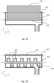
- Figure 2C shows the dosing blade 416 in the vertical position along the y-z plane, while the agitator 426 is in the horizontal position along the x-y plane. Note that the outer edge of the major surface of the dosing blade 416 passes close to the shaft of the agitator.
- Figure 2D shows the dosing blade 416 in the horizontal position and the agitator 426 in the vertical position.
- the agitator in this example has open protrusions 427 extending away from a central spine fixed to the agitator shaft 422.
- Such a configuration of the agitator has been observed to spread, during rotation of the agitator, the powder along the y- and x- direction of powder chamber by gravitational forces while it is being delivered to the powder chamber via outlet 454.
- the configuration of the agitator shown is by no means essential, though, and alternative configurations are possible; for example the protrusions may not form closed loops, instead they may be filled-in (e.g. in the form of paddles), or they may simply take the form of rods or vanes extending in opposite directions from the central spine forming a comb-like structure on either side, or they may not describe square loops but have rounded shapes instead.
- the agitator may rotate 90° or close to 90° out of phase with the dosing blade, so that one of the two extends vertically only when the other is in the horizontal "base" position.
- the close proximity of the dosing blade and the agitator in Figure 2 creates a vertical overlap ⁇ O' ( Figure 2A ) between the swept volume 414 and the agitation volume 424.
- the powder dosing system is further arranged such that the swept volume 414 partially accommodates the agitation volume 424 to create, in addition to the vertical overlap, a physical overlap in the vertical direction.
- the agitator 426 rotates about the agitator shaft 422 which defines an axis of rotation for the agitator.
- the dosing blade is arranged to extend to within close proximity of the axis of rotation of the agitator when the dosing blade sweeps through the swept volume.
- the radius of agitation substantially overlaps the radius of the swept volume.
- the rotation of the agitator is timed (i.e. synchronised) with respect to the rotation of the dosing blade.
- Such synchronisation could be by mechanical synchronisation, e.g. using gearing or one or more drive belts, or by means of electronic synchronisation.
- the vertical overlap ⁇ O' between the swept volume 414 and the agitation volume 424 need not comprise a physical overlap between the swept volume 414 and the agitation volume 424. Nevertheless, in either case, the vertical overlap 'O' helps to ensure that the powder above the agitator 426 remains in a free-flowing state within the swept volume 414. In addition, free-flowing powder is provided to the recirculation edge 428, the effect of which will be described in detail next, in relation to Figures 3 and 4 .
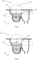
- Figure 3 shows the dosing system 40 of Figure 2 filled with powder 432.
- Figure 4 shows a dosing system 40' in which the dosing blade is arranged further above the agitator such that there is no overlap, in the vertical sense, between the swept volume 414 and the agitation volume 424.
- the height of a non-agitation region S' of the powder above the agitation volume 424 is higher than the corresponding height of a non-agitation volume S shown in Figure 3 for the dosing system 40.
- the effect of this is as follows. The further away the powder is from being agitated, and the larger the height of powder, the more likely the powder will settle, densify and form clumps.
- regions 434 of powder are present, which are regions not swept by either the dosing blade 416 or the agitator 426. These regions remain stagnant, and over time the powder in these stagnant regions also settles and densifies. If resulting clumps of powder fall back into the agitator region, they may not be rendered fully flowable again by the agitator. This can lead to clumps of denser powder being delivered to the swept volume 414 and ultimately to the work surface, where the clumps again will cause non-uniform areas in the spread layer over the build bed surface 12, and therefore may cause a faulty object.
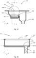
- the powder profile is affected by the degree of flowability of the powder, which may further compound the non-agitated height S'. This will be explained with respect to Figures 5A and 5B .
- the arrangement of the powder dosing system 40 comprises a powder recirculation edge 428 adjacent the agitator over which powder may fall into a recirculation tube 440.
- the powder falling over the recirculation edge 428 leaves the dosing system 40.
- the recirculation edge allows the dosing system to receive an oversupply of powder from the delivery mechanism so that the powder volume in the powder dosing system 40 self-regulates, since excess powder can freely flow over the recirculation edge to leave the dosing system and fall, for example, into an adjacent recirculation chamber.
- the delivery mechanism is an auger
- the auger may only be stopped during a dosing stroke of the dosing blade 416 during which powder is dosed to the work surface.
- the recirculation edge 428 therefore provides for passive regulation of the volume of powder in the powder chamber 430. Reliable regulation of this dosing system arrangement having a recirculation edge 428 may in turn be provided by ensuring that the powder remains in a free-flowing state, so that it can freely flow over the recirculation edge 428 to prevent overfilling the dosing chamber, and to maintain a consistent level of the swept powder volume 414. In this way, the dosing blade 416 may repeatedly dose a consistent volume of powder to the work surface and a repeatable uniform layer of powder may be spread over the build bed surface 12.
- the volume of powder in the swept volume 414 is indicated by the dotted area. It is located above the powder in the powder chamber that is not swept by the dosing blade. It can be seen, especially through comparison with Figure 5B showing a slightly lower recirculation edge height, how the height H of the recirculation edge 428 determines the swept volume 414.
- the swept volume is V1.
- the powder is delivered by the delivery mechanism to the powder chamber and agitated by the agitator to be in a free-flowing state. Once the agitated powder reaches the recirculation edge 428, volume V1 has been filled with powder and excess agitated powder falls over the recirculation edge 428.
- the volume V further depends on the surface profile of the powder. Without agitation, the profile is determined by the avalanche angle of the powder.
- the avalanche angle is slightly higher than the angle of repose of a powder, which is the slope at which a specific powder naturally rests. Powder slippage occurs if the powder slope is made steeper; this 'critical' angle is the avalanche angle. Therefore, when powder falls over the recirculation edge 428, this is due in part to the avalanche angle.
- the avalanche angle depends on the size and roughness of the powder particles, for example.
- the avalanche angle may be around 34-38° depending on the temperature and on the powder handling history (such as age, number of recirculation cycles through the printer) of the powder.
- the density of the powder also plays an important role.
- the avalanche angle reduces also, and for a free-flowing material the 'fluidised' avalanche angle is near zero. This has been observed near the recirculation edge 428 for the powder dosing system 40.
- the angle varies non-linearly with distance from the recirculation edge 428, so that above the shaft of the agitator in the vertical direction, the powder forms a small conical pile.
- the powder profile observed is not desirable since the non-agitation volume S' causes a higher, less fluidised avalanche angle compared to the powder dosing system 40.
- This causes the 'fluidised' angle of avalanche near the recirculation edge 428 to be higher, and a higher conical pile of steeper slope is formed above the agitator.
- the powder dosing system 40' therefore, there exists a wide range of powder densities above the agitator, and this system is therefore less reliable than the powder dosing system 40.
- the vertical separation between the axes of the dosing blade and the agitator was around 50mm.
- the height of the recirculation edge 428 of the powder dosing system 40 is comparatively higher than that required for the powder dosing system 40' due to the high degree of followability that can be achieved near the recirculation edge, leading to a very low fluidised avalanche angle near the recirculation edge.
- the vertical overlap between the swept volume 414 and agitation volume 424, in the vertical direction, in combination with a recirculation edge 428 that passively controls the volume of powder along the swept volume synergistically provide a powder dosing system that may ensure the deposition of a repeatably uniform layer of powder in an apparatus for manufacturing a three-dimensional object from powder.
- a further embodiment shown in Figure 7 provides for a powder chamber in which the dosing blade 416 cannot collide with the agitator 426, as in this embodiment, swept volume is arranged adjacent to the agitation volume 424, in a horizontal sense, such that the swept volume 414 excludes the agitation volume. In other words, the swept volume is located next to, or to one side of, the agitation volume.
- the powder chamber comprises an agitator chamber 420 which is in communication, with respect to the flow of powder, with the dosing chamber 410 via a dosing chamber edge 418.
- the agitator 426 shown is a rotating agitator of similar design to that of Figure 3 , and agitates the powder delivered to the agitator chamber over the agitation volume 424. Adjacent to the agitator on one side is the dosing chamber edge 418, and adjacent to the agitator on the opposite side is the recirculation edge 428.
- the dosing chamber edge 418 is located at a lower height, in the vertical direction, with respect to the height of the recirculation edge 428, so that agitated powder first falls over the dosing chamber edge 418 before it reaches a level high enough for excess agitated powder to fall over the recirculation edge 428.
- the swept volume 414 and the agitation volume 424 are each arranged adjacent to and at opposing sides of a dosing chamber edge 418, wherein the height of the dosing chamber edge is arranged, in a vertical sense, below the recirculation edge height.
- the dosing blade rotation describes a swept volume 414 that determines, based on the powder profile in the dosing chamber, the volume of powder delivered by the dosing blade 416 to the work surface.
- the swept volume 414 may be controlled by the height of the recirculation edge 428.
- the head of the powder within each chamber is kept small, and therefore prevents the agitated powder from densifying.
- the region of agitation is the region over which, in the vertical sense, the powder remains in a free-flowing state such that excess agitated powder can fall freely over the recirculation edge and into the recirculation tube. The extent of this region depends on the powder properties and the specific dimensions of the powder chamber, the dosing blade design, and the type and mode of operation of the reciprocating or vibrating agitator.
- a reciprocating or vibrating agitator instead of a rotating agitator may be particularly suitable in compact systems where it is not possible to install a powder chamber having an agitation chamber of appreciable depth. Instead, by using a reciprocating or vibrating agitator, the powder chamber depth is primarily defined by the depth of the dosing chamber 430.
- the reciprocating or vibrating agitator may be a mesh agitator.
- Figure 8A is a view down the powder chamber along a dosing blade shaft 412, along the y-direction.
- a mesh agitator 425 is located above the floor of the powder chamber 430 and adjacent the swept volume 414 of the dosing blade 416.
- the mesh comprises openings that allow delivered powder to pass through the mesh from the powder chamber floor upwards along the vertical direction.
- a side view of the chamber along section A-A' is shown in Figure 8B .
- the mesh is reciprocated laterally, along the y-direction, along an axis of reciprocation indicated by the lower dashed line as indicated by the arrow. Additionally, it may also be reciprocated laterally along the x-direction, or width, of the chamber. Alternatively, or additionally, the mesh may be arranged to vibrate, for example along the z-direction.
- the reciprocating or vibrating agitator may be a predominantly solid plate in cases where powder is delivered to the powder chamber above the agitator.
- the plate may comprise parallel raised features along the width (x-direction) of the plate that improve the friction between the plate and the powder.
- the reciprocating or vibrating agitator distributes the powder along the length of the powder chamber and keeps it in a free-flowing state over the region of agitation. Due to the vertical overlap between the region of agitation and the swept volume 414, the recirculation edge maintains a consistent powder volume along the swept volume, since the excess powder overflows over the recirculation edge and out of the dosing system as long as the delivery mechanism overdelivers powder into the dosing system.
- the tangent plane of the swept volume of the dosing blade is located in close proximity to the plane of the reciprocating or vibrating agitator. This means that the dosing blade removes substantially all of the agitated volume agitated above the plane surface of the agitator.
- the vertical overlap between the swept volume 414 and the region of agitation, in the vertical direction, in combination with the recirculation edge 428 that passively controls the volume of powder along the swept volume synergistically provide a powder dosing system that may ensure the deposition of a repeatably uniform layer of powder in an apparatus for manufacturing a three-dimensional object from powder.
- the dosing blade may be arranged to sweep about a horizontal axis.
- the rotating agitator may be arranged to rotate about a horizontal axis.
- the supply of delivered powder may be continuous or periodic.
- the presence of the powder recirculation edge 428 adjacent to the agitator allows powder to flow out of the dosing system and thus prevents the powder chamber from overfilling while allowing the delivery mechanism (e.g. the auger screw) to deliver powder at periodic intervals, or continuously, without needing to be actively managed.
- the recirculation edge 428 therefore provides for passive regulation of the volume of powder in the powder chamber or the dosing system.
- the powder may be delivered continuously with the auger screw rotating at full duty. In other cases, this may not be necessary, and the auger screw may only be activated periodically, for example only 50% of the time, such as 5 seconds on, 5 seconds off. This may prevent significant heat generation in the powder due to the auger screw.
- the auger may only be stopped during a dosing stroke of the dosing blade to dose powder to the work surface.
- a nearcontinuous operation of the auger may reduce or prevent the occurrence of polymer stagnation in the auger, which can lead to powder agglomerates being supplied into the dosing system.
- the recirculation edge height may be located at a position that lies above the lowest point of the swept volume.
- the recirculation edge 428 may extend adjacent and parallel to a tangent plane to the agitation volume 424.
- the height of the recirculation edge 428 is adjustable so as to vary the volume of the agitated powder that is dosed to the work surface.
- This provides for an apparatus that can be tuned for the use of different powders. Since different powders are likely to have different flow characteristics, e.g. avalanche angles and 'fluidised' avalanche angles, the volume of the powder along the swept volume 414 may have to be adjusted so that a required volume of powder can be delivered to the work surface. Additionally, or instead, the volume of the powder being dosed to the work surface may need to be adjusted.
- different powders are likely to have different flow characteristics, e.g. avalanche angles and 'fluidised' avalanche angles
- the volume of the powder along the swept volume 414 may have to be adjusted so that a required volume of powder can be delivered to the work surface. Additionally, or instead, the volume of the powder being dosed to the work surface may need to be adjusted.
- the recirculation edge 428 may be part of a slideable recirculation gate, which is a plate movable with respect to the powder chamber such that the height of the recirculation edge may be altered.
- a slideable recirculation gate which is a plate movable with respect to the powder chamber such that the height of the recirculation edge may be altered.
- Figure 9 where the slideable recirculation gate 421 is arranged to be translated linearly along wall 423 of the agitation chamber, where wall 423 of the agitation chamber is the wall nearest the recirculation tube 440. In this way, the height of the recirculation edge 428 is adjustable vertically.
- the recirculation edge may extend adjacent and parallel to a tangent plane to the swept volume 414.
- the plane of the recirculation gate 421, or the wall comprising the recirculation edge is parallel to the tangent plane of the swept volume, and is located as close as possible to the tangent plane of the swept volume, thereby minimising the dead space between the swept volume 414 and the recirculation edge 428 (or the recirculation gate).
- the direction of translation of the recirculation edge may extend along a parallel in close proximity to the tangent plane of the swept volume so as to avoid significant regions of dead space of powder.
- the slideable recirculation gate 421 may be a metal plate attached to a linear translation motor 429 via a slot in the wall 423, while the motor 429 is attached to wall 423. Such an arrangement would give in-process control of the edge height 428. Alternative implementations of achieving electronic translation of the recirculation gate will be apparent to the skilled person.
- a manually adjustable version of a slideable recirculation gate 421 may involve bolting the slideable recirculation gate 421 to the wall 423 of the agitation chamber.
- the slideable recirculation gate 421 in this case may have vertical slots through which the gate can be bolted to the wall 423.
- the bolts may be recessed by providing a chamfer on the slot edge so as to avoid the bolts protruding into the agitation chamber.
- a manually adjustable recirculation edge height may be suitable where the recirculation edge height is only required to be adjusted on build process set-up and not during processing.
- Using a motor to electronically adjust the recirculation edge allows for in-process changes of the height of the recirculation edge 428, so as to adjust the dosed powder volume by allowing more powder to accumulate in the swept volume of the dosing blade.
- the control over the recirculation edge height may be provided by an edge height controller which may for example be arranged to access conversion values of required powder volume (and/or layer thickness) to a suitable edge height for a specific type of powder.
- the required powder volume may be provided ad-hoc by the user, or it may be provided as part of a build process sequence for the layer by layer formation of the object.
- a build process controller may send process information to the edge height controller as necessary to cause the edge height controller to adjust the edge height at specific timings within the build process.
- Figure 10 illustrates a process flow during priming of powder dosing system 40. Priming is required each time the recirculation edge 428 is adjusted, for example when selecting the correct edge height when the powder chamber is filled with new powder, or each time the recirculation edge height is adjusted during a build process.
- a method for adjusting the recirculation edge height of the powder dosing system comprises the steps of:
- a similar method may be used to find corresponding values for edge height versus layer thickness, and optionally, the powder level of the swept volume.
- a look-up table or similar may be provided to the edge height controller to refer to during in-process adjustment of the edge height.
- Step (c) for assessing the volume of powder may for example comprise actuating the dosing blade to dose a dosed volume of the agitated powder to the work surface;
- the step of assessing the volume of powder delivered to the swept volume may comprise weighing the delivered volume. Additionally, or alternatively, the step of assessing the volume of powder delivered to the swept volume may comprise sensing the level of powder within the swept volume.
- the step of adjusting the recirculation edge height comprises the step of actuating a translational mechanism arranged to adjust the recirculation edge height in response to one of weighing, sensing, or spreading the powder.
- the translational mechanism may be a linear motor.
- the powder dosing system of any of the above-described embodiments may comprise a powder level sensor for detecting the powder level within the swept volume, for example so as to monitor the powder level of the swept volume.
- Such a powder level sensor 419 is shown in Figure 9 , mounted to a wall of the dosing chamber. Since the agitator of the above-described embodiments keeps the powder in a free-flowing state, the powder profile inside the dosing chamber is of a reliable shape and a sensed level of the powder may reliably be converted into a swept volume.
- the sensed powder level may be used to monitor for problems within the dosing chamber, for example malfunction of the agitator or recirculation edge motor, and/or to assess whether the volume of powder within the swept volume requires adjustment.
- the powder level sensor may for example be used during adjustment of the recirculation edge.
- step (c) may comprise sensing the powder level, for example to assess whether the swept volume requires adjustment, to monitor the powder level during adjustment of the recirculation edge, and/or to create reference data of the powder properties relevant to the build process, for example a look up table of powder level reading against powder volume/layer thickness and edge height.
- the look up table may be used during the build process to adjust the recirculation edge height for a required layer thickness.
- Sensing of the powder level may also be done to test for malfunction once reference data of the powder properties has been created, for example where the set height does not result in a sensed powder level that matches closely with an expected powder level according to the reference data.
- the powder dosing system may comprise a recirculation edge sensor.
- a recirculation edge sensor 436 may be located in a wall of the recirculation tube 440.
- the recirculation edge sensor 436 may sense whether excess agitated powder is falling over the edge 428, and signal to the edge height controller that the dosing chamber has been filled.
- the edge height controller may next interrogate the powder level sensor 419 to test whether the powder level corresponds to the expected level. Where the powder level does not correspond to the expected level for the set edge height, the recirculation edge height controller may signal a malfunction to the build process controller.
- the recirculation edge sensor may monitor the height of the recirculation edge, for example such that the actual height may be compared to an expected height by the recirculation edge height controller.
- the functions of the powder level sensor and the recirculation edge sensor may be fulfilled by the same sensor.
- the recirculation edge height may be adjusted in response to an adjustment of the distributed layer thickness.
- a method of forming a three-dimensional object from powder using a powder dosing system 40 wherein the recirculation edge height is adjustable by controlling a translational mechanism.
- buffer layers are distributed by the distribution sled without forming any object layers.
- the buffer layers are pre-warmed and help to ensure an even temperature distribution of the build bed surface.
- the first powder layer for the object build is distributed by the distribution sled and processed by operating the printing sled.
- the overall buffer layer thickness is typically several microns thick by distributing 100-500 layers, each of the order of 100nm thick.
- some build layers or some buffer layers may require a different thickness than other build layers, or some build layers may require a different dosed powder volume than other layers to achieve the same layer thickness.
- the buffer layers may have a thickness higher than that of the object layers.
- the layer thickness may be changed by lowering the build bed by a distance equal to the required layer thickness. To ensure enough powder is dosed to the work surface, the required volume plus a small excess is dosed to the work surface. For each layer therefore, excess powder is present at the end of the pass of the powder distribution device, and the excess powder is either disposed of or recycled.
- the dosed volume may need to be adjusted during the build in response to the cross section sintered in the previous layer.
- the sintered areas are much denser than the unsintered areas, for example the density of unsintered powder volume may be around 0.4-0.6g/cm 3 compared to the density of the sintered powder volume of 0.9-1.1g/cm 3 .
- the sintered areas in the processed powder layer therefore typically present sunken areas with respect to the unsintered powder surface, and present a volume that needs to be infilled with powder when a new layer of powder is distributed over the top.
- the additional volume of powder required to be dosed may be significant, e.g. 1-10% (possibly more).
- the recirculation edge height is adjusted for the required dosed powder volume, the powder chamber is filled by the powder delivery mechanism until agitated powder falls over the recirculation edge and out of the dosing system, and the required swept volume is achieved. Once the swept volume is dosed to the work surface from the dosing blade, it is distributed across the build bed surface by the roller.
- two or more layers may be distributed on the build bed surface from powder dosed from the swept volume of the dosing blade such that a first layer is formed from a first swept volume and a second layer is formed from a second swept volume, wherein the swept volume is adjusted from a first volume to a second volume by controlling the translational mechanism.
- the thickness of the first layer may be the same as the thickness of the second layer, and the second swept volume may be adjusted based on the area covered by the object in the first layer. This means that sintered, denser areas can be infilled with sufficient powder when the next layer is distributed, to ensure that the next layer is of the required thickness.
- the operation of the dosing chamber system having an adjustable recirculation edge height that may be adjusted by a motorised translational mechanism may be controlled by a recirculation edge height controller system.
- the recirculation edge height controller system may be a distinct controller or it may be part of a build process controller.
- a control system for adjusting the recirculation edge height of the powder dosing system of the above-described embodiments comprises, according to the invention, a recirculation edge height controller arranged to receive an input of a required powder level.
- the recirculation edge height controller is arranged to determine, for the required powder level, a corresponding recirculation edge height, and to control a translational mechanism for adjusting the recirculation edge height to the corresponding recirculation edge height.
- the required powder level may be provided in the form of one of required layer thickness, required powder volume within the swept volume (required swept powder volume), or the actual required swept powder level within the dosing chamber, for example, or a request to increase/decrease the swept powder level by a percentile.
- the edge height controller may receive the value for the required recirculation edge height.
- the controller may be adapted to calculate, based on data of the sintered cross sections of a previous layer, the powder volume required to be dosed for the next layer.
- the powder level may be a qualitative or quantitative property - for example it may be a specific quantitative value, or it may be provided as a qualitative "low", "medium” or "high” level.
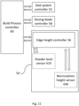
- a recirculation edge height control system 54 receives a command from a build process controller 60 to alter the height of the recirculation edge such that a required layer thickness can be achieved from the swept volume dosed to the work surface by the dosing blade.
- the edge height controller 56 is arranged to determine from the required thickness a corresponding edge height value from a closest thickness match.
- the recirculation edge height controller controls the translational mechanism, such as a linear motor, of the recirculation gate, and the translational mechanism moves the recirculation edge to the required height.
- the recirculation edge height controller 56 may send a signal to the build process controller 60 that the edge height has been adjusted.
- the build process controller may then send a signal to the dosing blade controller 58 to actuate the dosing blade, whereupon the dosing blade doses the powder volume within the swept volume to the work surface, and the dosed volume of powder can be assessed.
- Assessment of the dosed powder volume may be done for example by the build process controller sending a signal to the sled system controller controlling the motion and functions of the sleds, whereupon the sled system controller causes the distribution sled to pass over the build bed surface to distribute the dosed powder over the build bed surface, and the thickness and uniformity of the distributed layer may be assessed.
- the recirculation edge height controller may determine the required edge height from data, for example data in the form or a look up table or graph, correlating values of required layer thickness and/or required swept powder volume against corresponding edge height. This data may for example be provided by the method described for Figure 10 .
- the data may be in the form of a graph of layer thickness (or swept volume) versus edge height, extrapolating between measured values.
- the required thickness may be provided with a tolerance margin, such that the actual thickness to be achieved falls within an acceptable range of thicknesses.
- the edge height controller system 54 may comprise one or more sensors. Specifically, the control system may comprise a powder level sensor arranged to detect a powder level of the swept volume. The edge height controller is arranged to receive the detected swept powder volume level, to determine a required swept powder volume level corresponding to the required powder level, and to determine whether the detected swept powder volume level is different from the required swept powder volume level. If the detected swept powder volume level is different from the required swept powder volume level, the edge height controller is further arranged to determine an adjustment to be made to the recirculation edge height to achieve the required swept powder volume level, and to control the translational mechanism to perform said adjustment.
- Powder level sensor 419 may be located in the dosing chamber 410 so as to detect the swept powder volume level.
- the controller may receive a required layer thickness instead of a required swept powder volume level, wherein the edge height controller is further arranged to determine a corresponding swept powder volume level in order to compare it to the detected swept powder volume level.
- Implementations of the powder dosing system may comprise a recirculation edge sensor arranged to detect excess agitated powder falling over the recirculation edge, and/or to detect the height of the recirculation edge.
- the edge height controller may interrogate sensor 419 to assess the swept powder volume level in the dosing chamber, and compare it to the required swept powder volume level. In this case, the edge height controller determines from the required layer thickness the corresponding required swept powder volume level to compare against the detected swept powder volume level. If the required swept powder volume level is not the same as the detected swept powder volume level, within a margin of tolerance, the priming process of the powder chamber is not complete.
- the edge height controller may send to the build process controller 60 a signal that the required swept powder volume level has been reached, and the build process controller can begin, or resume, a test or build procedure.
- control system may further comprise a recirculation edge sensor arranged to detect excess agitated powder falling over the recirculation edge, and/or to detect the height of the recirculation edge.
- the recirculation edge sensor 436 is part of the edge height controller system.
- the priming of the powder chamber may be complete once the edge height controller determines from the recirculation edge sensor 436 that powder is falling over the recirculation edge and out of the dosing system.
- the output of powder level sensor 419 may be used in addition to determine by the edge height controller 56 that the priming process is complete, or it may be used by the edge height controller 56 to test, once the recirculation edge sensor 436 senses powder falling over the edge, whether the detected swept powder volume level corresponds to an expected swept powder volume level based on data available to the edge height controller. If the detected swept powder volume level does not correspond to the swept powder volume level expected based on the recirculation edge height, despite the recirculation edge sensor signalling that priming is complete, the edge height controller may signal malfunction to the build process controller 60.
- the edge height controller may adjust the recirculation edge height suitably and signal to the build process controller that the dosing chamber system is ready for the next priming step.
- the build process controller may then send a signal to the delivery mechanism to reinitiate the powder delivery.
- the delivery mechanism may be operated continuously or periodically during adjustment of the recirculation edge height rather than being switched off.
- the recirculation edge sensor 436 may further be used to detect the height of the recirculation edge, so that the edge height controller 56 may compare the set edge height value against the detected height value to assess whether a malfunction of the recirculation edge, for example of the translational mechanism, has occurred.
- the edge height controller may be arranged to receive a required powder layer thickness in respect of the build bed surface
- the recirculation edge height controller is arranged to determine the corresponding recirculation edge height corresponding to the required swept powder volume level from stored data.
- the corresponding swept powder volume level may be determined based on the surface profile of the swept powder volume.
- the data may be stored in the form of a look-up table or graph in memory comprised within the edge height controller, within the edge height controller system, or within the build process controller.
- the swept powder volume is intended to be the same as, or closely corresponding to, the dosed powder volume.
- the swept powder volume becomes the dosed powder volume once it is delivered to the work surface.
- the dosed volume is slightly smaller than the swept volume.
- References to powder level are intended to refer to the height of the swept powder volume within the dosing chamber.
- the sensor therefore detects the height of the powder volume within the chamber.
- a swept volume or to an agitation volume these are intended to represent the three-dimensional spaces directly occupied by rotational devices such as the dosing blade and the rotational agitator during their operation.
- the volumes may be cylindrical, or they may take different shapes depending on the mode of rotation, eccentricity of axis, and the design of the protrusions of the agitator and the dosing blade.
- the profile of the powder in the powder chamber may correspond to the profile shown in the Figures more strongly near and/or above the powder delivery outlet, and be less pronounced further away along the powder chamber from the powder delivery outlet. Nonetheless, even a reduced region that spans a portion of the length of the powder chamber but that is subject to powder settling and densifying will compromise the quality of the layer spread on the work surface, and therefore the quality of the object. While the specific powder profile is dependent on the type of powder, environmental conditions, and the design of the powder dosing system, the above embodiments apply similarly to different powder profiles.
- the powder volume in the dosing chamber is required to be adjusted by stop-starting the auger to regulate the amount of powder in the dosing system. If the auger runs a little lean, the powder volume in the dosing chamber recedes and the dosing blade starts to deliver a reduced amount of powder. This can eventually lead to non-uniform and/or incomplete distribution of one or more powder layers, which in turn leads to failure of the manufactured object.
- the presence of the recirculation edge in the above embodiments and their various implementations allows the dosing systems 40 to receive a continuous oversupply of powder from the delivery mechanism so that the powder volume in the dosing system self-regulates, since excess powder can freely flow over the recirculation edge and out of the dosing system, to fall for example into an adjacent recirculation chamber.
- in-process measuring and adjusting of powder level in the dosing system is not necessary to prevent powder starvation or overfilling of the dosing system, for example due to running the auger only intermittently or at an incorrect speed.
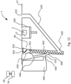
- the self-regulating powder volume of the dosing system 40 may have additional effects depending on the powder handling system of the apparatus 1. This will now be described with reference to Figure 12 , which shows an apparatus 1 having the dosing system 40 according to an embodiment, a recirculation loop and a return loop:
Landscapes
- Engineering & Computer Science (AREA)
- Chemical & Material Sciences (AREA)
- Materials Engineering (AREA)
- Manufacturing & Machinery (AREA)
- Physics & Mathematics (AREA)
- Optics & Photonics (AREA)
- Mechanical Engineering (AREA)
- Automation & Control Theory (AREA)
- Analytical Chemistry (AREA)
- Fluid Mechanics (AREA)
- General Physics & Mathematics (AREA)
- Plasma & Fusion (AREA)
- Powder Metallurgy (AREA)
Claims (14)
- Pulverdosiersystem (40) für eine Vorrichtung zur Herstellung eines dreidimensionalen Objekts aus Pulver, wobei das Pulverdosiersystem (40) umfasst:eine Pulverkammer (430), die eine Rührwerkskammer (420) und eine Dosierkammer (410) umfasst, wobei die Rührwerkskammer (420) ein rotierendes Rührwerk (426) umfasst, das so angeordnet ist, dass es einen Vorrat an zugeführtem Pulver mittels Rotation durch ein Rührvolumen (424) rührt, das sich aus der Erstreckung des rotierenden Rührwerks zu einer Rotationsachse (422) des Rührwerks (426) bestimmt; undeine Dosierklinge (416), die so angeordnet ist, dass sie ein dosiertes Volumen des Pulvers auf eine Arbeitsfläche (13) dosiert, die eine Aufbaubettoberfläche (12) umfasst, indem sie durch ein überstrichenes Volumen (414) streicht, das sich aus der Erstreckung der Dosierklinge (416) von einer Rotationsachse (412) der Dosierklinge (416) bestimmt;wobei sich das überstrichene Volumen (414) vertikal bemessen über dem Rührvolumen (424) angeordnet ist, und das Rührvolumen (424) vertikal bemessen überlappt, so dass das dosierte Volumen des Pulvers ein gerührtes Pulver ist;wobei die Pulverkammer (430) ferner eine Rezirkulationskante (428) benachbart zu dem Rührwerk (426) umfasst und so angeordnet ist, dass überschüssiges gerührtes Pulver frei über die Rezirkulationskante (428) und aus dem Pulverdosiersystem (40) fließen kann; undwobei die Rezirkulationskante (428) eine einstellbare Rezirkulationskantenhöhe aufweist, um das Volumen des gerührten Pulvers, das auf die Arbeitsfläche (13) dosiert wird, zu variieren.
- Pulverdosiersystem (40) nach Anspruch 1, wobei der Dosierklinge (416) so angeordnet ist, dass sie sich bis in unmittelbare Nähe der Rotationsachse (422) des Rührwerks (426) erstreckt, wenn die Dosierklinge (416) das überstrichene Volumen (414) überstreicht, so dass eine vertikale Überlappung zwischen dem überstrichenen Volumen (414) und dem Rührvolumen (424) besteht.
- Pulverdosiersystem (40) nach Anspruch 1 oder Anspruch 2, wobei die Rührwerkskammer (420) unterhalb der Dosierkammer (410) angeordnet ist.
- Pulverdosiersystem (40) nach Anspruch 1, wobei die Rührwerkskammer (420) auf einer Seite der Dosierkammer (410) angeordnet ist, so dass das überstrichene Volumen (414) horizontal bemessen neben dem Rührvolumen (424) angeordnet ist, so dass das überstrichene Volumen (414) das Rührvolumen (424) ausschließt.
- Pulverdosiersystem (40) nach Anspruch 4, wobei eine Dosierkammerkante (418) zwischen der Dosierkammer (410) und der Rührwerkskammer (420) und benachbart zu einer Seite des Rührwerks (426) angeordnet ist und die Rezirkulationskante (428) benachbart zu der gegenüberliegenden Seite des Rührwerks (426) angeordnet ist; und wobei die Höhe der Dosierkammerkante (418) vertikal bemessen unterhalb der Höhe der Rezirkulationskantenhöhe angeordnet ist, so dass gerührtes Pulver zuerst über die Dosierkammerkante (418) fällt, bevor es einen Pegel erreicht, der hoch genug ist, dass überschüssiges gerührtes Pulver über die Rezirkulationskante (428) fließen kann.
- Pulverdosiersystem (40) nach Anspruch 4, wobei das überstrichene Volumen (414) und das Rührvolumen (424) jeweils benachbart zu und auf gegenüberliegenden Seiten einer Dosierkammerkante (418) angeordnet sind, wobei die Dosierkammerkante (418) in vertikaler Richtung unterhalb der Rezirkulationskantenhöhe angeordnet ist.
- Pulverdosiersystem (40) für eine Vorrichtung zur Herstellung eines dreidimensionalen Objekts aus Pulver, wobei das Pulverdosiersystem (40) umfasst:eine Pulverkammer (430), die eine Dosierkammer (410) und ein hin- und hergehendes oder vibrierendes Rührwerk umfasst, das so angeordnet ist, dass es einen Vorrat an zugeführtem Pulver in einem Rührbereich rührt, um gerührtes Pulver bereitzustellen; wobei die Dosierkammer (410) eine Dosierklinge (416) umfasst, die eine Rotationsachse (412) aufweist und so angeordnet ist, dass sie über ein überstrichenes Volumen (414) streicht, das sich aus der Erstreckung der Dosierklinge (416) von der Rotationsachse (412) bestimmt, und einen Teil des Pulvers an eine Arbeitsfläche (13) abgibt, die eine Aufbaubettoberfläche (12) umfasst, wobei das überstrichene Volumen (414) vertikal bemessen oberhalb und neben dem Rührwerk angeordnet ist, so dass der Teil des Pulvers gerührtes Pulver ist;wobei das Pulverdosiersystem (40) ferner eine Rezirkulationskante (428) aufweist, die an das überstrichene Volumen (414) angrenzt und so angeordnet ist, dass überschüssiges gerührtes Pulver frei aus dem Bereich des Rührens über die Rezirkulationskante (428) und aus dem Pulverdosiersystem (40) heraus fließen kann; undwobei die Rezirkulationskante (428) eine einstellbare Rezirkulationskantenhöhe aufweist, um das Volumen des gerührten Pulvers, das auf die Arbeitsfläche (13) dosiert wird, zu variieren.
- Pulverdosiersystem (40) nach Anspruch 7, wobei das hin- und hergehende oder vibrierende Rührwerk ein Gitterrührwerk (425) ist.
- Pulverdosiersystem (40) nach Anspruch 7 oder Anspruch 8, wobei die Tangentialebene des überstrichenen Volumens (414) der Dosierklinge (416) in unmittelbarer Nähe der Ebene des hin- und hergehenden oder vibrierenden Rührwerks liegt, so dass die Dosierklinge (416) im Wesentlichen das gesamte gerührte Volumen oberhalb der Ebene des Rührwerks abführt.
- Pulverdosiersystem (40) nach einem der Ansprüche 1 bis 3 oder nach einem der Ansprüche 7 bis 9, dadurch gekennzeichnet, dass sich die Rezirkulationskante (428) benachbart und parallel zu einer Tangentialebene zu dem überstrichenen Volumen (414) erstreckt.
- Pulverdosiersystem (40) nach einem der vorhergehenden Ansprüche, ferner umfassend einen Pulverpegelsensor (419) zum Erfassen des Pulverpegels innerhalb des überstrichenen Volumens (414).
- Pulverdosiersystem (40) nach einem der vorhergehenden Ansprüche, ferner umfassend einen Rezirkulationskantensensor (436), der so angeordnet ist, dass er überschüssiges gerührtes Pulver, das über die Rezirkulationskante (428) fällt, erfasst und/oder die Höhe der Rezirkulationskante erfasst.
- Verfahren zum Einstellen der Rezirkulationskantenhöhe des Pulverdosiersystems (40) nach einem der vorhergehenden Ansprüche, wobei das Verfahren die folgenden Schritte umfasst:(a) Einstellen der Höhe der Rezirkulationskante;(b) Zuführen eines Pulvervorrats in das überstrichene Volumen (414) der Dosierklinge (416), während das zugeführte Pulver unter Verwendung des Rührwerks gerührt wird, bis überschüssiges gerührtes Pulver über die Rezirkulationskante (428) und aus dem Pulverdosiersystem (40) fließt;(c) Ermitteln des Volumens des Pulvers, das in das überstrichene Volumen (414) abgegeben wird; und(d) wenn das ermittelte Pulvervolumen nicht innerhalb einer Toleranz eines erforderlichen Volumens liegt, Einstellen der Höhe der Rezirkulationskante und Wiederholung von Schritt b); oder,(e) wenn das ermittelte Volumen innerhalb der Toleranz eines erforderlichen Volumens liegt, Einstellen der Höhe der Rezirkulationskante auf die eingestellte Rezirkulationskantenhöhe.
- Steuersystem (54) zum Einstellen der Rezirkulationskantenhöhe des Pulverdosiersystems (40) nach einem der Ansprüche 1 bis 12, wobei das Steuersystem (54) einen Rezirkulationskantenhöhenregler (56) umfasst, der so angeordnet ist, dass er einen erforderlichen Pulverpegel aufnimmt;
wobei der Rezirkulationskantenhöhenregler (56) so angeordnet ist, dass er für den erforderlichen Pulverpegel eine entsprechende Rezirkulationskantenhöhe bestimmt, und dass er einen Translationsmechanismus (429) zum Einstellen der Rezirkulationskantenhöhe auf die entsprechende Rezirkulationskantenhöhe einstellt.
Applications Claiming Priority (2)
| Application Number | Priority Date | Filing Date | Title |
|---|---|---|---|
| GB1819681.6A GB2579560B (en) | 2018-12-03 | 2018-12-03 | Powder dosing system |
| PCT/GB2019/053413 WO2020115468A1 (en) | 2018-12-03 | 2019-12-03 | Powder dosing system |
Publications (2)
| Publication Number | Publication Date |
|---|---|
| EP3890976A1 EP3890976A1 (de) | 2021-10-13 |
| EP3890976B1 true EP3890976B1 (de) | 2025-01-29 |
Family
ID=65024917
Family Applications (1)
| Application Number | Title | Priority Date | Filing Date |
|---|---|---|---|
| EP19816860.1A Active EP3890976B1 (de) | 2018-12-03 | 2019-12-03 | Pulverdosiersystem |
Country Status (6)
| Country | Link |
|---|---|
| US (1) | US20220009170A1 (de) |
| EP (1) | EP3890976B1 (de) |
| JP (1) | JP3237906U (de) |
| CN (1) | CN216914840U (de) |
| GB (1) | GB2579560B (de) |
| WO (1) | WO2020115468A1 (de) |
Families Citing this family (8)
| Publication number | Priority date | Publication date | Assignee | Title |
|---|---|---|---|---|
| WO2021054949A1 (en) * | 2019-09-18 | 2021-03-25 | Hewlett-Packard Development Company, L.P. | Build material supply unit |
| WO2022086867A1 (en) | 2020-10-20 | 2022-04-28 | General Electric Company | Printing assemblies and methods for using the same |
| EP4232261B1 (de) | 2020-10-20 | 2024-09-04 | General Electric Company | Druck- und nachbeschichtungsanordnung für system zur generativen fertigung und verfahren zur verwendung davon |
| US12194681B2 (en) | 2020-10-21 | 2025-01-14 | General Electric Company | Material supply system and method for using the same |
| US12600087B2 (en) | 2020-10-29 | 2026-04-14 | General Electric Company | Print head assembly and methods for using the same |
| US12533848B2 (en) | 2020-10-29 | 2026-01-27 | General Electric Company | Additive manufacturing apparatuses with removable build boxes and build box management systems |
| US12552100B2 (en) | 2020-10-29 | 2026-02-17 | General Electric Company | Additive manufacturing apparatuses and methods for using the same |
| CN117086330A (zh) * | 2023-08-21 | 2023-11-21 | 深圳市华阳新材料科技有限公司 | 一种高精度铺粉方法 |
Citations (4)
| Publication number | Priority date | Publication date | Assignee | Title |
|---|---|---|---|---|
| WO2017005301A1 (en) * | 2015-07-07 | 2017-01-12 | Hewlett-Packard Development Company L.P. | Supplying build material |
| WO2017184166A1 (en) * | 2016-04-22 | 2017-10-26 | Hewlett-Packard Development Company, L.P. | Moveable belt to carry a build material |
| WO2017196326A1 (en) * | 2016-05-12 | 2017-11-16 | Hewlett-Packard Development Company, L.P. | Distributing powder |
| GB2568521A (en) * | 2017-11-17 | 2019-05-22 | Xaar 3D Ltd | Apparatus for the manufacture of three-dimensional objects |
Family Cites Families (3)
| Publication number | Priority date | Publication date | Assignee | Title |
|---|---|---|---|---|
| GB201216636D0 (en) * | 2012-09-18 | 2012-10-31 | Blueprinter Aps | Powder feed mechanism for a three-dimensional printer |
| CN107848200B (zh) * | 2015-11-23 | 2020-07-28 | 惠普发展公司有限责任合伙企业 | 供应构造材料 |
| WO2018056988A1 (en) * | 2016-09-22 | 2018-03-29 | Hewlett-Packard Development Company, L.P. | Dispensing powder |
-
2018
- 2018-12-03 GB GB1819681.6A patent/GB2579560B/en active Active
-
2019
- 2019-12-03 US US17/297,433 patent/US20220009170A1/en not_active Abandoned
- 2019-12-03 WO PCT/GB2019/053413 patent/WO2020115468A1/en not_active Ceased
- 2019-12-03 JP JP2021600083U patent/JP3237906U/ja active Active
- 2019-12-03 CN CN201990001216.6U patent/CN216914840U/zh active Active
- 2019-12-03 EP EP19816860.1A patent/EP3890976B1/de active Active
Patent Citations (4)
| Publication number | Priority date | Publication date | Assignee | Title |
|---|---|---|---|---|
| WO2017005301A1 (en) * | 2015-07-07 | 2017-01-12 | Hewlett-Packard Development Company L.P. | Supplying build material |
| WO2017184166A1 (en) * | 2016-04-22 | 2017-10-26 | Hewlett-Packard Development Company, L.P. | Moveable belt to carry a build material |
| WO2017196326A1 (en) * | 2016-05-12 | 2017-11-16 | Hewlett-Packard Development Company, L.P. | Distributing powder |
| GB2568521A (en) * | 2017-11-17 | 2019-05-22 | Xaar 3D Ltd | Apparatus for the manufacture of three-dimensional objects |
Also Published As
| Publication number | Publication date |
|---|---|
| CN216914840U (zh) | 2022-07-08 |
| WO2020115468A1 (en) | 2020-06-11 |
| GB2579560A (en) | 2020-07-01 |
| JP3237906U (ja) | 2022-06-16 |
| GB201819681D0 (en) | 2019-01-16 |
| EP3890976A1 (de) | 2021-10-13 |
| US20220009170A1 (en) | 2022-01-13 |
| GB2579560B (en) | 2021-10-06 |
Similar Documents
| Publication | Publication Date | Title |
|---|---|---|
| US20220009170A1 (en) | Powder dosing system | |
| US20250242543A1 (en) | Apparatus for the manufacture of three-dimensional objects | |
| JP3232579U (ja) | 三次元物体の製造のための装置 | |
| US7799253B2 (en) | Method of, and apparatus for, applying flowable material across a surface | |
| TWI781232B (zh) | 分配系統與在積層製造設備中分配粉末的方法 | |
| CN104010750B (zh) | 用于粉末基增材制造的机器和方法 | |
| RU2641115C1 (ru) | Устройство нанесения слоя для 3d-принтера и способ для нанесения двух слоев конструкционного материала в виде частиц | |
| US11485074B2 (en) | Supplying build material | |
| US11173658B2 (en) | Recoating unit and device for producing a three-dimensional object | |
| US12226960B2 (en) | Method and apparatus for layer thickness control in additive manufacturing | |
| CN111356590A (zh) | 用于制造三维物体的方法和设备 | |
| CN110520279B (zh) | 用于3d打印机的计量机构 | |
| US20190061254A1 (en) | Moveable belt to carry a build material | |
| US20010010205A1 (en) | Powder feeding apparatus having an adjustable feed width and a method for adjusting the feed width of the apparatus | |
| EP3400126B1 (de) | Verteilung von pulver | |
| US12565003B2 (en) | Techniques for powder delivery in additive fabrication and related systems and methods | |
| US20220410270A1 (en) | Loading build material powder for a 3d printer | |
| WO2024149998A1 (en) | Build material supply systems for apparatus for the layerwise manufacture of 3d objects and method of build material transport |
Legal Events
| Date | Code | Title | Description |
|---|---|---|---|
| STAA | Information on the status of an ep patent application or granted ep patent |
Free format text: STATUS: UNKNOWN |
|
| STAA | Information on the status of an ep patent application or granted ep patent |
Free format text: STATUS: THE INTERNATIONAL PUBLICATION HAS BEEN MADE |
|
| PUAI | Public reference made under article 153(3) epc to a published international application that has entered the european phase |
Free format text: ORIGINAL CODE: 0009012 |
|
| STAA | Information on the status of an ep patent application or granted ep patent |
Free format text: STATUS: REQUEST FOR EXAMINATION WAS MADE |
|
| 17P | Request for examination filed |
Effective date: 20210630 |
|
| AK | Designated contracting states |
Kind code of ref document: A1 Designated state(s): AL AT BE BG CH CY CZ DE DK EE ES FI FR GB GR HR HU IE IS IT LI LT LU LV MC MK MT NL NO PL PT RO RS SE SI SK SM TR |
|
| RAP3 | Party data changed (applicant data changed or rights of an application transferred) |
Owner name: STRATASYS POWDER PRODUCTION LTD |
|
| DAV | Request for validation of the european patent (deleted) | ||
| DAX | Request for extension of the european patent (deleted) | ||
| RAP3 | Party data changed (applicant data changed or rights of an application transferred) |
Owner name: STRATASYS POWDER PRODUCTION LTD |
|
| RIN1 | Information on inventor provided before grant (corrected) |
Inventor name: HARTMANN, ANDERS Inventor name: TJELLESEN, FREDERIK |
|
| STAA | Information on the status of an ep patent application or granted ep patent |
Free format text: STATUS: EXAMINATION IS IN PROGRESS |
|
| RIC1 | Information provided on ipc code assigned before grant |
Ipc: B22F 12/90 20210101ALI20231003BHEP Ipc: B33Y 10/00 20150101ALI20231003BHEP Ipc: B33Y 50/02 20150101ALI20231003BHEP Ipc: B22F 10/85 20210101ALI20231003BHEP Ipc: B22F 12/57 20210101ALI20231003BHEP Ipc: B22F 10/34 20210101ALI20231003BHEP Ipc: B22F 3/105 20060101ALI20231003BHEP Ipc: B33Y 40/10 20200101ALI20231003BHEP Ipc: B29C 64/343 20170101ALI20231003BHEP Ipc: B29C 64/307 20170101ALI20231003BHEP Ipc: B29C 64/255 20170101ALI20231003BHEP Ipc: B29C 64/241 20170101ALI20231003BHEP Ipc: B29C 64/153 20170101ALI20231003BHEP Ipc: B33Y 30/00 20150101AFI20231003BHEP |
|
| PUAG | Search results despatched under rule 164(2) epc together with communication from examining division |
Free format text: ORIGINAL CODE: 0009017 |
|
| 17Q | First examination report despatched |
Effective date: 20231107 |
|
| RIC1 | Information provided on ipc code assigned before grant |
Ipc: B22F 12/90 20210101ALI20231102BHEP Ipc: B33Y 10/00 20150101ALI20231102BHEP Ipc: B33Y 50/02 20150101ALI20231102BHEP Ipc: B22F 10/85 20210101ALI20231102BHEP Ipc: B22F 12/57 20210101ALI20231102BHEP Ipc: B22F 10/34 20210101ALI20231102BHEP Ipc: B22F 3/105 20060101ALI20231102BHEP Ipc: B33Y 40/10 20200101ALI20231102BHEP Ipc: B29C 64/343 20170101ALI20231102BHEP Ipc: B29C 64/307 20170101ALI20231102BHEP Ipc: B29C 64/255 20170101ALI20231102BHEP Ipc: B29C 64/241 20170101ALI20231102BHEP Ipc: B29C 64/153 20170101ALI20231102BHEP Ipc: B33Y 30/00 20150101AFI20231102BHEP |
|
| 17Q | First examination report despatched |
Effective date: 20231110 |
|
| RIC1 | Information provided on ipc code assigned before grant |
Ipc: B22F 12/90 20210101ALI20231108BHEP Ipc: B33Y 10/00 20150101ALI20231108BHEP Ipc: B33Y 50/02 20150101ALI20231108BHEP Ipc: B22F 10/85 20210101ALI20231108BHEP Ipc: B22F 12/57 20210101ALI20231108BHEP Ipc: B22F 10/34 20210101ALI20231108BHEP Ipc: B22F 3/105 20060101ALI20231108BHEP Ipc: B33Y 40/10 20200101ALI20231108BHEP Ipc: B29C 64/343 20170101ALI20231108BHEP Ipc: B29C 64/307 20170101ALI20231108BHEP Ipc: B29C 64/255 20170101ALI20231108BHEP Ipc: B29C 64/241 20170101ALI20231108BHEP Ipc: B29C 64/153 20170101ALI20231108BHEP Ipc: B33Y 30/00 20150101AFI20231108BHEP |
|
| 17Q | First examination report despatched |
Effective date: 20231117 |
|
| B565 | Issuance of search results under rule 164(2) epc |
Effective date: 20231117 |
|
| RIC1 | Information provided on ipc code assigned before grant |
Ipc: B22F 12/90 20210101ALI20231114BHEP Ipc: B33Y 10/00 20150101ALI20231114BHEP Ipc: B33Y 50/02 20150101ALI20231114BHEP Ipc: B22F 10/85 20210101ALI20231114BHEP Ipc: B22F 12/57 20210101ALI20231114BHEP Ipc: B22F 10/34 20210101ALI20231114BHEP Ipc: B22F 3/105 20060101ALI20231114BHEP Ipc: B33Y 40/10 20200101ALI20231114BHEP Ipc: B29C 64/343 20170101ALI20231114BHEP Ipc: B29C 64/307 20170101ALI20231114BHEP Ipc: B29C 64/255 20170101ALI20231114BHEP Ipc: B29C 64/241 20170101ALI20231114BHEP Ipc: B29C 64/153 20170101ALI20231114BHEP Ipc: B33Y 30/00 20150101AFI20231114BHEP |
|
| GRAP | Despatch of communication of intention to grant a patent |
Free format text: ORIGINAL CODE: EPIDOSNIGR1 |
|
| STAA | Information on the status of an ep patent application or granted ep patent |
Free format text: STATUS: GRANT OF PATENT IS INTENDED |
|
| RIC1 | Information provided on ipc code assigned before grant |
Ipc: B22F 10/28 20210101ALI20240527BHEP Ipc: B22F 12/90 20210101ALI20240527BHEP Ipc: B33Y 10/00 20150101ALI20240527BHEP Ipc: B33Y 50/02 20150101ALI20240527BHEP Ipc: B22F 10/85 20210101ALI20240527BHEP Ipc: B22F 12/57 20210101ALI20240527BHEP Ipc: B22F 10/34 20210101ALI20240527BHEP Ipc: B33Y 40/10 20200101ALI20240527BHEP Ipc: B29C 64/343 20170101ALI20240527BHEP Ipc: B29C 64/307 20170101ALI20240527BHEP Ipc: B29C 64/255 20170101ALI20240527BHEP Ipc: B29C 64/241 20170101ALI20240527BHEP Ipc: B29C 64/153 20170101ALI20240527BHEP Ipc: B33Y 30/00 20150101AFI20240527BHEP |
|
| INTG | Intention to grant announced |
Effective date: 20240701 |
|
| GRAS | Grant fee paid |
Free format text: ORIGINAL CODE: EPIDOSNIGR3 |
|
| RBV | Designated contracting states (corrected) |
Designated state(s): AL AT BE BG CH CY CZ DE DK EE ES FI FR GR HR HU IE IS IT LI LT LU LV MC MK MT NL NO PL PT RO RS SE SI SK SM TR |
|
| GRAA | (expected) grant |
Free format text: ORIGINAL CODE: 0009210 |
|
| STAA | Information on the status of an ep patent application or granted ep patent |
Free format text: STATUS: THE PATENT HAS BEEN GRANTED |
|
| AK | Designated contracting states |
Kind code of ref document: B1 Designated state(s): AL AT BE BG CH CY CZ DE DK EE ES FI FR GR HR HU IE IS IT LI LT LU LV MC MK MT NL NO PL PT RO RS SE SI SK SM TR |
|
| REG | Reference to a national code |
Ref country code: CH Ref legal event code: EP |
|
| REG | Reference to a national code |
Ref country code: DE Ref legal event code: R096 Ref document number: 602019065449 Country of ref document: DE |
|
| REG | Reference to a national code |
Ref country code: IE Ref legal event code: FG4D |
|
| RAP4 | Party data changed (patent owner data changed or rights of a patent transferred) |
Owner name: STRATASYS POWDER PRODUCTION LTD |
|
| REG | Reference to a national code |
Ref country code: NL Ref legal event code: MP Effective date: 20250129 |
|
| PG25 | Lapsed in a contracting state [announced via postgrant information from national office to epo] |
Ref country code: NL Free format text: LAPSE BECAUSE OF FAILURE TO SUBMIT A TRANSLATION OF THE DESCRIPTION OR TO PAY THE FEE WITHIN THE PRESCRIBED TIME-LIMIT Effective date: 20250129 |
|
| PG25 | Lapsed in a contracting state [announced via postgrant information from national office to epo] |
Ref country code: RS Free format text: LAPSE BECAUSE OF FAILURE TO SUBMIT A TRANSLATION OF THE DESCRIPTION OR TO PAY THE FEE WITHIN THE PRESCRIBED TIME-LIMIT Effective date: 20250429 |
|
| PG25 | Lapsed in a contracting state [announced via postgrant information from national office to epo] |
Ref country code: FI Free format text: LAPSE BECAUSE OF FAILURE TO SUBMIT A TRANSLATION OF THE DESCRIPTION OR TO PAY THE FEE WITHIN THE PRESCRIBED TIME-LIMIT Effective date: 20250129 |
|
| PG25 | Lapsed in a contracting state [announced via postgrant information from national office to epo] |
Ref country code: PL Free format text: LAPSE BECAUSE OF FAILURE TO SUBMIT A TRANSLATION OF THE DESCRIPTION OR TO PAY THE FEE WITHIN THE PRESCRIBED TIME-LIMIT Effective date: 20250129 |
|
| PG25 | Lapsed in a contracting state [announced via postgrant information from national office to epo] |
Ref country code: ES Free format text: LAPSE BECAUSE OF FAILURE TO SUBMIT A TRANSLATION OF THE DESCRIPTION OR TO PAY THE FEE WITHIN THE PRESCRIBED TIME-LIMIT Effective date: 20250129 |
|
| REG | Reference to a national code |
Ref country code: LT Ref legal event code: MG9D |
|
| PG25 | Lapsed in a contracting state [announced via postgrant information from national office to epo] |
Ref country code: IS Free format text: LAPSE BECAUSE OF FAILURE TO SUBMIT A TRANSLATION OF THE DESCRIPTION OR TO PAY THE FEE WITHIN THE PRESCRIBED TIME-LIMIT Effective date: 20250529 Ref country code: NO Free format text: LAPSE BECAUSE OF FAILURE TO SUBMIT A TRANSLATION OF THE DESCRIPTION OR TO PAY THE FEE WITHIN THE PRESCRIBED TIME-LIMIT Effective date: 20250429 |
|
| REG | Reference to a national code |
Ref country code: AT Ref legal event code: MK05 Ref document number: 1763069 Country of ref document: AT Kind code of ref document: T Effective date: 20250129 |
|
| PG25 | Lapsed in a contracting state [announced via postgrant information from national office to epo] |
Ref country code: HR Free format text: LAPSE BECAUSE OF FAILURE TO SUBMIT A TRANSLATION OF THE DESCRIPTION OR TO PAY THE FEE WITHIN THE PRESCRIBED TIME-LIMIT Effective date: 20250129 |
|
| PG25 | Lapsed in a contracting state [announced via postgrant information from national office to epo] |
Ref country code: LV Free format text: LAPSE BECAUSE OF FAILURE TO SUBMIT A TRANSLATION OF THE DESCRIPTION OR TO PAY THE FEE WITHIN THE PRESCRIBED TIME-LIMIT Effective date: 20250129 Ref country code: PT Free format text: LAPSE BECAUSE OF FAILURE TO SUBMIT A TRANSLATION OF THE DESCRIPTION OR TO PAY THE FEE WITHIN THE PRESCRIBED TIME-LIMIT Effective date: 20250529 |
|
| PG25 | Lapsed in a contracting state [announced via postgrant information from national office to epo] |
Ref country code: GR Free format text: LAPSE BECAUSE OF FAILURE TO SUBMIT A TRANSLATION OF THE DESCRIPTION OR TO PAY THE FEE WITHIN THE PRESCRIBED TIME-LIMIT Effective date: 20250430 Ref country code: BG Free format text: LAPSE BECAUSE OF FAILURE TO SUBMIT A TRANSLATION OF THE DESCRIPTION OR TO PAY THE FEE WITHIN THE PRESCRIBED TIME-LIMIT Effective date: 20250129 |
|
| PG25 | Lapsed in a contracting state [announced via postgrant information from national office to epo] |
Ref country code: AT Free format text: LAPSE BECAUSE OF FAILURE TO SUBMIT A TRANSLATION OF THE DESCRIPTION OR TO PAY THE FEE WITHIN THE PRESCRIBED TIME-LIMIT Effective date: 20250129 |
|
| PG25 | Lapsed in a contracting state [announced via postgrant information from national office to epo] |
Ref country code: SE Free format text: LAPSE BECAUSE OF FAILURE TO SUBMIT A TRANSLATION OF THE DESCRIPTION OR TO PAY THE FEE WITHIN THE PRESCRIBED TIME-LIMIT Effective date: 20250129 |
|
| PG25 | Lapsed in a contracting state [announced via postgrant information from national office to epo] |
Ref country code: SM Free format text: LAPSE BECAUSE OF FAILURE TO SUBMIT A TRANSLATION OF THE DESCRIPTION OR TO PAY THE FEE WITHIN THE PRESCRIBED TIME-LIMIT Effective date: 20250129 |
|
| PG25 | Lapsed in a contracting state [announced via postgrant information from national office to epo] |
Ref country code: DK Free format text: LAPSE BECAUSE OF FAILURE TO SUBMIT A TRANSLATION OF THE DESCRIPTION OR TO PAY THE FEE WITHIN THE PRESCRIBED TIME-LIMIT Effective date: 20250129 |
|
| PG25 | Lapsed in a contracting state [announced via postgrant information from national office to epo] |
Ref country code: IT Free format text: LAPSE BECAUSE OF FAILURE TO SUBMIT A TRANSLATION OF THE DESCRIPTION OR TO PAY THE FEE WITHIN THE PRESCRIBED TIME-LIMIT Effective date: 20250129 |
|
| PG25 | Lapsed in a contracting state [announced via postgrant information from national office to epo] |
Ref country code: CZ Free format text: LAPSE BECAUSE OF FAILURE TO SUBMIT A TRANSLATION OF THE DESCRIPTION OR TO PAY THE FEE WITHIN THE PRESCRIBED TIME-LIMIT Effective date: 20250129 Ref country code: EE Free format text: LAPSE BECAUSE OF FAILURE TO SUBMIT A TRANSLATION OF THE DESCRIPTION OR TO PAY THE FEE WITHIN THE PRESCRIBED TIME-LIMIT Effective date: 20250129 |
|
| PG25 | Lapsed in a contracting state [announced via postgrant information from national office to epo] |
Ref country code: RO Free format text: LAPSE BECAUSE OF FAILURE TO SUBMIT A TRANSLATION OF THE DESCRIPTION OR TO PAY THE FEE WITHIN THE PRESCRIBED TIME-LIMIT Effective date: 20250129 |
|
| PG25 | Lapsed in a contracting state [announced via postgrant information from national office to epo] |
Ref country code: SK Free format text: LAPSE BECAUSE OF FAILURE TO SUBMIT A TRANSLATION OF THE DESCRIPTION OR TO PAY THE FEE WITHIN THE PRESCRIBED TIME-LIMIT Effective date: 20250129 |
|
| REG | Reference to a national code |
Ref country code: DE Ref legal event code: R097 Ref document number: 602019065449 Country of ref document: DE |
|
| PLBE | No opposition filed within time limit |
Free format text: ORIGINAL CODE: 0009261 |
|
| STAA | Information on the status of an ep patent application or granted ep patent |
Free format text: STATUS: NO OPPOSITION FILED WITHIN TIME LIMIT |
|
| 26N | No opposition filed |
Effective date: 20251030 |
|
| PGFP | Annual fee paid to national office [announced via postgrant information from national office to epo] |
Ref country code: DE Payment date: 20251126 Year of fee payment: 7 |
|
| PGFP | Annual fee paid to national office [announced via postgrant information from national office to epo] |
Ref country code: FR Payment date: 20251120 Year of fee payment: 7 |