EP3890936B1 - Procédé de fabrication de corps de pale d'éolienne - Google Patents
Procédé de fabrication de corps de pale d'éolienne Download PDFInfo
- Publication number
- EP3890936B1 EP3890936B1 EP19817954.1A EP19817954A EP3890936B1 EP 3890936 B1 EP3890936 B1 EP 3890936B1 EP 19817954 A EP19817954 A EP 19817954A EP 3890936 B1 EP3890936 B1 EP 3890936B1
- Authority
- EP
- European Patent Office
- Prior art keywords
- insert
- mould
- mould surface
- blade
- constant cross
- Prior art date
- Legal status (The legal status is an assumption and is not a legal conclusion. Google has not performed a legal analysis and makes no representation as to the accuracy of the status listed.)
- Active
Links
- 238000004519 manufacturing process Methods 0.000 title claims description 27
- 238000000034 method Methods 0.000 claims description 40
- 230000001419 dependent effect Effects 0.000 claims description 7
- 230000008569 process Effects 0.000 description 16
- 239000000853 adhesive Substances 0.000 description 9
- 230000001070 adhesive effect Effects 0.000 description 9
- 239000000463 material Substances 0.000 description 9
- 239000011324 bead Substances 0.000 description 8
- 230000000295 complement effect Effects 0.000 description 8
- 239000003365 glass fiber Substances 0.000 description 7
- 229920002430 Fibre-reinforced plastic Polymers 0.000 description 5
- 238000010586 diagram Methods 0.000 description 5
- 239000011162 core material Substances 0.000 description 4
- 239000004744 fabric Substances 0.000 description 4
- 239000011151 fibre-reinforced plastic Substances 0.000 description 4
- 229920001343 polytetrafluoroethylene Polymers 0.000 description 4
- 239000004810 polytetrafluoroethylene Substances 0.000 description 4
- 239000003570 air Substances 0.000 description 3
- 230000008859 change Effects 0.000 description 3
- 230000001154 acute effect Effects 0.000 description 2
- 239000003795 chemical substances by application Substances 0.000 description 2
- 230000003247 decreasing effect Effects 0.000 description 2
- 229920005989 resin Polymers 0.000 description 2
- 239000011347 resin Substances 0.000 description 2
- 230000000717 retained effect Effects 0.000 description 2
- 239000000565 sealant Substances 0.000 description 2
- 230000007704 transition Effects 0.000 description 2
- OKTJSMMVPCPJKN-UHFFFAOYSA-N Carbon Chemical compound [C] OKTJSMMVPCPJKN-UHFFFAOYSA-N 0.000 description 1
- 239000004593 Epoxy Substances 0.000 description 1
- -1 Polytetrafluoroethylene Polymers 0.000 description 1
- 239000012080 ambient air Substances 0.000 description 1
- 230000000712 assembly Effects 0.000 description 1
- 238000000429 assembly Methods 0.000 description 1
- 230000008901 benefit Effects 0.000 description 1
- 229920005549 butyl rubber Polymers 0.000 description 1
- 229910052799 carbon Inorganic materials 0.000 description 1
- 238000009734 composite fabrication Methods 0.000 description 1
- 239000002131 composite material Substances 0.000 description 1
- 238000010276 construction Methods 0.000 description 1
- 238000009826 distribution Methods 0.000 description 1
- 239000000945 filler Substances 0.000 description 1
- 239000006260 foam Substances 0.000 description 1
- 239000011521 glass Substances 0.000 description 1
- 238000010438 heat treatment Methods 0.000 description 1
- 238000005470 impregnation Methods 0.000 description 1
- 238000001802 infusion Methods 0.000 description 1
- 238000009434 installation Methods 0.000 description 1
- 238000005304 joining Methods 0.000 description 1
- 238000000465 moulding Methods 0.000 description 1
- 230000002093 peripheral effect Effects 0.000 description 1
- 239000004033 plastic Substances 0.000 description 1
- 229920003023 plastic Polymers 0.000 description 1
- 239000002952 polymeric resin Substances 0.000 description 1
- 230000001603 reducing effect Effects 0.000 description 1
- 238000009745 resin transfer moulding Methods 0.000 description 1
- 238000007789 sealing Methods 0.000 description 1
- 239000007787 solid Substances 0.000 description 1
- 229920003002 synthetic resin Polymers 0.000 description 1
Images


Classifications
-
- B—PERFORMING OPERATIONS; TRANSPORTING
- B29—WORKING OF PLASTICS; WORKING OF SUBSTANCES IN A PLASTIC STATE IN GENERAL
- B29C—SHAPING OR JOINING OF PLASTICS; SHAPING OF MATERIAL IN A PLASTIC STATE, NOT OTHERWISE PROVIDED FOR; AFTER-TREATMENT OF THE SHAPED PRODUCTS, e.g. REPAIRING
- B29C33/00—Moulds or cores; Details thereof or accessories therefor
- B29C33/30—Mounting, exchanging or centering
- B29C33/306—Exchangeable mould parts, e.g. cassette moulds, mould inserts
-
- B—PERFORMING OPERATIONS; TRANSPORTING
- B29—WORKING OF PLASTICS; WORKING OF SUBSTANCES IN A PLASTIC STATE IN GENERAL
- B29C—SHAPING OR JOINING OF PLASTICS; SHAPING OF MATERIAL IN A PLASTIC STATE, NOT OTHERWISE PROVIDED FOR; AFTER-TREATMENT OF THE SHAPED PRODUCTS, e.g. REPAIRING
- B29C33/00—Moulds or cores; Details thereof or accessories therefor
- B29C33/30—Mounting, exchanging or centering
- B29C33/308—Adjustable moulds
-
- B—PERFORMING OPERATIONS; TRANSPORTING
- B29—WORKING OF PLASTICS; WORKING OF SUBSTANCES IN A PLASTIC STATE IN GENERAL
- B29C—SHAPING OR JOINING OF PLASTICS; SHAPING OF MATERIAL IN A PLASTIC STATE, NOT OTHERWISE PROVIDED FOR; AFTER-TREATMENT OF THE SHAPED PRODUCTS, e.g. REPAIRING
- B29C43/00—Compression moulding, i.e. applying external pressure to flow the moulding material; Apparatus therefor
- B29C43/02—Compression moulding, i.e. applying external pressure to flow the moulding material; Apparatus therefor of articles of definite length, i.e. discrete articles
- B29C43/10—Isostatic pressing, i.e. using non-rigid pressure-exerting members against rigid parts or dies
- B29C43/12—Isostatic pressing, i.e. using non-rigid pressure-exerting members against rigid parts or dies using bags surrounding the moulding material or using membranes contacting the moulding material
-
- B—PERFORMING OPERATIONS; TRANSPORTING
- B29—WORKING OF PLASTICS; WORKING OF SUBSTANCES IN A PLASTIC STATE IN GENERAL
- B29C—SHAPING OR JOINING OF PLASTICS; SHAPING OF MATERIAL IN A PLASTIC STATE, NOT OTHERWISE PROVIDED FOR; AFTER-TREATMENT OF THE SHAPED PRODUCTS, e.g. REPAIRING
- B29C43/00—Compression moulding, i.e. applying external pressure to flow the moulding material; Apparatus therefor
- B29C43/02—Compression moulding, i.e. applying external pressure to flow the moulding material; Apparatus therefor of articles of definite length, i.e. discrete articles
- B29C43/14—Compression moulding, i.e. applying external pressure to flow the moulding material; Apparatus therefor of articles of definite length, i.e. discrete articles in several steps
-
- B—PERFORMING OPERATIONS; TRANSPORTING
- B29—WORKING OF PLASTICS; WORKING OF SUBSTANCES IN A PLASTIC STATE IN GENERAL
- B29C—SHAPING OR JOINING OF PLASTICS; SHAPING OF MATERIAL IN A PLASTIC STATE, NOT OTHERWISE PROVIDED FOR; AFTER-TREATMENT OF THE SHAPED PRODUCTS, e.g. REPAIRING
- B29C70/00—Shaping composites, i.e. plastics material comprising reinforcements, fillers or preformed parts, e.g. inserts
- B29C70/04—Shaping composites, i.e. plastics material comprising reinforcements, fillers or preformed parts, e.g. inserts comprising reinforcements only, e.g. self-reinforcing plastics
- B29C70/28—Shaping operations therefor
- B29C70/30—Shaping by lay-up, i.e. applying fibres, tape or broadsheet on a mould, former or core; Shaping by spray-up, i.e. spraying of fibres on a mould, former or core
- B29C70/302—Details of the edges of fibre composites, e.g. edge finishing or means to avoid delamination
-
- B—PERFORMING OPERATIONS; TRANSPORTING
- B29—WORKING OF PLASTICS; WORKING OF SUBSTANCES IN A PLASTIC STATE IN GENERAL
- B29C—SHAPING OR JOINING OF PLASTICS; SHAPING OF MATERIAL IN A PLASTIC STATE, NOT OTHERWISE PROVIDED FOR; AFTER-TREATMENT OF THE SHAPED PRODUCTS, e.g. REPAIRING
- B29C70/00—Shaping composites, i.e. plastics material comprising reinforcements, fillers or preformed parts, e.g. inserts
- B29C70/04—Shaping composites, i.e. plastics material comprising reinforcements, fillers or preformed parts, e.g. inserts comprising reinforcements only, e.g. self-reinforcing plastics
- B29C70/28—Shaping operations therefor
- B29C70/40—Shaping or impregnating by compression not applied
- B29C70/42—Shaping or impregnating by compression not applied for producing articles of definite length, i.e. discrete articles
- B29C70/44—Shaping or impregnating by compression not applied for producing articles of definite length, i.e. discrete articles using isostatic pressure, e.g. pressure difference-moulding, vacuum bag-moulding, autoclave-moulding or expanding rubber-moulding
- B29C70/446—Moulding structures having an axis of symmetry or at least one channel, e.g. tubular structures, frames
-
- B—PERFORMING OPERATIONS; TRANSPORTING
- B29—WORKING OF PLASTICS; WORKING OF SUBSTANCES IN A PLASTIC STATE IN GENERAL
- B29D—PRODUCING PARTICULAR ARTICLES FROM PLASTICS OR FROM SUBSTANCES IN A PLASTIC STATE
- B29D99/00—Subject matter not provided for in other groups of this subclass
- B29D99/0025—Producing blades or the like, e.g. blades for turbines, propellers, or wings
- B29D99/0028—Producing blades or the like, e.g. blades for turbines, propellers, or wings hollow blades
-
- F—MECHANICAL ENGINEERING; LIGHTING; HEATING; WEAPONS; BLASTING
- F03—MACHINES OR ENGINES FOR LIQUIDS; WIND, SPRING, OR WEIGHT MOTORS; PRODUCING MECHANICAL POWER OR A REACTIVE PROPULSIVE THRUST, NOT OTHERWISE PROVIDED FOR
- F03D—WIND MOTORS
- F03D13/00—Assembly, mounting or commissioning of wind motors; Arrangements specially adapted for transporting wind motor components
- F03D13/10—Assembly of wind motors; Arrangements for erecting wind motors
-
- B—PERFORMING OPERATIONS; TRANSPORTING
- B29—WORKING OF PLASTICS; WORKING OF SUBSTANCES IN A PLASTIC STATE IN GENERAL
- B29L—INDEXING SCHEME ASSOCIATED WITH SUBCLASS B29C, RELATING TO PARTICULAR ARTICLES
- B29L2031/00—Other particular articles
- B29L2031/08—Blades for rotors, stators, fans, turbines or the like, e.g. screw propellers
- B29L2031/082—Blades, e.g. for helicopters
- B29L2031/085—Wind turbine blades
-
- F—MECHANICAL ENGINEERING; LIGHTING; HEATING; WEAPONS; BLASTING
- F05—INDEXING SCHEMES RELATING TO ENGINES OR PUMPS IN VARIOUS SUBCLASSES OF CLASSES F01-F04
- F05B—INDEXING SCHEME RELATING TO WIND, SPRING, WEIGHT, INERTIA OR LIKE MOTORS, TO MACHINES OR ENGINES FOR LIQUIDS COVERED BY SUBCLASSES F03B, F03D AND F03G
- F05B2230/00—Manufacture
- F05B2230/50—Building or constructing in particular ways
-
- F—MECHANICAL ENGINEERING; LIGHTING; HEATING; WEAPONS; BLASTING
- F05—INDEXING SCHEMES RELATING TO ENGINES OR PUMPS IN VARIOUS SUBCLASSES OF CLASSES F01-F04
- F05B—INDEXING SCHEME RELATING TO WIND, SPRING, WEIGHT, INERTIA OR LIKE MOTORS, TO MACHINES OR ENGINES FOR LIQUIDS COVERED BY SUBCLASSES F03B, F03D AND F03G
- F05B2240/00—Components
- F05B2240/20—Rotors
- F05B2240/30—Characteristics of rotor blades, i.e. of any element transforming dynamic fluid energy to or from rotational energy and being attached to a rotor
- F05B2240/302—Segmented or sectional blades
-
- Y—GENERAL TAGGING OF NEW TECHNOLOGICAL DEVELOPMENTS; GENERAL TAGGING OF CROSS-SECTIONAL TECHNOLOGIES SPANNING OVER SEVERAL SECTIONS OF THE IPC; TECHNICAL SUBJECTS COVERED BY FORMER USPC CROSS-REFERENCE ART COLLECTIONS [XRACs] AND DIGESTS
- Y02—TECHNOLOGIES OR APPLICATIONS FOR MITIGATION OR ADAPTATION AGAINST CLIMATE CHANGE
- Y02E—REDUCTION OF GREENHOUSE GAS [GHG] EMISSIONS, RELATED TO ENERGY GENERATION, TRANSMISSION OR DISTRIBUTION
- Y02E10/00—Energy generation through renewable energy sources
- Y02E10/70—Wind energy
- Y02E10/72—Wind turbines with rotation axis in wind direction
-
- Y—GENERAL TAGGING OF NEW TECHNOLOGICAL DEVELOPMENTS; GENERAL TAGGING OF CROSS-SECTIONAL TECHNOLOGIES SPANNING OVER SEVERAL SECTIONS OF THE IPC; TECHNICAL SUBJECTS COVERED BY FORMER USPC CROSS-REFERENCE ART COLLECTIONS [XRACs] AND DIGESTS
- Y02—TECHNOLOGIES OR APPLICATIONS FOR MITIGATION OR ADAPTATION AGAINST CLIMATE CHANGE
- Y02P—CLIMATE CHANGE MITIGATION TECHNOLOGIES IN THE PRODUCTION OR PROCESSING OF GOODS
- Y02P70/00—Climate change mitigation technologies in the production process for final industrial or consumer products
- Y02P70/50—Manufacturing or production processes characterised by the final manufactured product
Definitions
- the present invention relates to a wind turbine blade body manufacturing method, and a wind turbine blade body manufacturing apparatus.
- the present invention provides improvements in wind turbine blade manufacturing.
- Modern wind turbine blades typically comprise a blade shell having a laminate structure of composite construction.
- the shell is commonly manufactured using a prepreg or vacuum-assisted resin infusion process in a female mould.
- Wind turbine blades are of considerable length, at present up to 80 meters in length and the moulds in which the blades are formed have a substantial cost.
- manufacturing a new length of rotor blade requires the manufacturing of a new mould with significant cost.
- WO2014095856 describes a variable moulding device for manufacturing the shell of a wind turbine blade, where an insert is placed into a mould.
- DE102014001445 describes the production of rotor blades of different sizes in a mould.
- EP2700812 describes mould assemblies for wind turbine blades where variable length moulds include standard tip sections.
- DE102012223810 describes a mould device for a wind turbine rotor blade with an insert for changing the shape of the mould.
- WO2017088883A1 discloses a mould having a mould surface for forming a first wind turbine blade. A removable insert is placed on the mould surface, to form a modified mould surface for forming a second blade body which is shorter than the first blade body. Thereby, a single mould can be used to manufacture two blade bodies of different length. This significantly reduces mould costs, since it increases flexibility in wind turbine blade production, and removes the need for a complete mould for the second blade. There is nevertheless a desire to reduce costs further in wind turbine blade production.
- the present invention thus aims to reduce costs in wind turbine blade production.
- the insert may present an insert mould surface.
- the combined mould surface is used to form the first and second blade bodies.
- the length of the combined mould surface depends on the position of the insert along the primary mould surface.
- the first and second positions may be distributed along the longitudinal direction of the primary mould surface. Placing the insert on the primary mould surface may result in a portion of the primary mould surface to be excluded from the combined mould surface.
- the mould may be elongated, and parallel with the primary mould surface.
- the mould may have a mould root end, at which the primary mould surface is arranged to form a root end of a blade body.
- the mould may have a mould distal end, at an end of the mould which is opposite to the root end.
- the first and second positions of the insert may be towards the distal end of the mould.
- Moving the blade insert from the first position to the second position, or vice versa provides for using the mould for producing blade bodies of different lengths.
- the invention provides for using the insert for producing the first as well as the second blade body.
- the mould itself does not need to be provided with a part for forming a tip of the blade bodies. This simplifies the production of the mould, thereby saving costs.
- a portion of the primary mould surface may present a shape which is similar to, or the same as, the shape of the insert mould surface.
- the primary mould surface may, without the insert, allow for the forming of a further, third blade body.
- the need for a complete mould for the third blade is removed. Thereby, the cost for such a mould is saved.
- the first and second blade bodies may each comprise a wind turbine blade shell or half shell.
- the first and second blade bodies may each extend from a respective root end to a respective tip end.
- the mould may be a part of an apparatus in the form of a mould system. Thereby, the mould could be a first mould, the system comprising a second mould.
- the first and second moulds may be adapted to form a respective blade body, in the form of a respective blade half shell.
- the mould system may be adapted to join the half shells, possibly with an intermediate structure, to form a wind turbine blade.
- the system may be provided with a turner assembly, joining the moulds and being adapted to turn one of the moulds over the other one, to bring the mould halves together for being joined.
- the step of providing a mould may comprise providing a first mould, the method further comprising providing a second mould having an elongated mould surface, placing a second movable insert on the mould surface of the second mould, in a further first position, and forming, with the second insert in the further first position, a further first blade body having the first length.
- the first blade bodies may be joined to form a first blade.
- the method may further comprise placing the second insert on the mould surface of the second mould, in a further second position, and forming, with the second insert in the further second position, a further second blade body having the second length.
- the second blade bodies may be joined to form a second blade.
- the primary mould surface may extend from a mould root end to a mould tip end.
- the tip end of the primary mould surface may, or may not, have a shape for forming a tip end of a blade body.
- the primary mould surface extends from a mould root end to a mould tip end
- the primary mould surface comprises a portion presenting a constant cross-section.
- the steps of placing the insert, in the first and second positions may comprise placing the insert with a proximal end thereof facing toward the mould root end, and placing the proximal end within the constant cross-section portion.
- the proximal end has a shape which is substantially the same as the cross-sectional shape of the constant cross-section portion.
- the mould insert can be placed at any position between two extreme positions. Such extreme positions may be at opposite ends of the constant cross-section portion.
- the insert may have a shape which is complementary to the constant cross-section portion. Thereby, the length of the blade bodies produced may be infinitely variable within the limits provided by the constant cross-section portion.
- the insert may be formed with a rib structure, for example as described in said WO2017088883A1 .
- the primary mould surface comprising a portion presenting a constant cross-section means that two 2-dimentional cuts of the primary mould surface, at any two separated respective positions along the constant cross-section, will be the same. As described closer below, a twist of the primary mould surface may change, and the primary mould surface may be curved in the longitudinal direction. Thus, one of the 2-dimentional cuts may be rotated in relation to the other.
- blade bodies may be produced with lengths differing in a stepwise manner, e.g. by 100-2000 mm, or 200-1000 mm, from one blade body to another.
- blade lengths may be varied within a wind farm, from some wind turbines to others, in a manner which increases the energy output of the windfarm.
- AEP annual energy production
- Embodiments of the invention provide for producing blades for such wind farms, without the need for excessive mould investments.
- a difference, at the first position and at the second position, of the orientation of the insert around a longitudinal axis of the primary mould surface is linearly dependent on the distance between the first position and the second position.
- the primary mould surface comprises a portion presenting a constant cross-section
- a twist of the primary mould surface may change, in the constant cross-section portion, linearly in the longitudinal direction of the primary mould surface.
- the insert may have a form which is complementary to the linearly changing twist of the primary mould surface.
- the mould may be altered by moving the insert from the first position to the second position, without any special provisions needed in view of the changing primary mould surface twist.
- blade bodies of different lengths, each with a change in twist may be easily produced.
- a difference, at the first position and at the second position, of the orientation of the insert around a lateral axis of the primary mould surface is linearly dependent on the distance between the first position and the second position.
- at least a part of the primary mould surface may be curved in the longitudinal direction so as to provide a longitudinal bend on the blade bodies, the curvature of the primary mould surface being constant in the constant cross-section portion.
- Such a bend may be referred to as a pre-bend.
- the insert may have a form which is complementary to the constant curvature primary mould surface.
- the mould may the altered by moving the insert from the first position to the second position, without any special provisions needed in view of the curved primary mould surface.
- blade bodies of different lengths, each with a longitudinal bend may be easily produced.
- the insert may be secured in the first and second positions in a variety of manners.
- a gap may be provided between the insert and the primary mould surface.
- a vacuum may be applied between the insert and the mould to retain the insert in position on the primary mould surface.
- the vacuum is applied to the gap between the insert and the primary mould surface.
- the insert may extend over a side surface of the mould and may be clamped to the mould.
- the side surface of the mould may have a negative draft angle.
- the steps of placing the insert, in the first and second positions comprises fixing the insert in a lateral direction of the primary mould surface, by means of a mechanical locking arrangement extending along at least one of opposite longitudinal edges of the primary mould surface.
- the mechanical locking arrangement may comprise e.g. a track.
- a track may extend along both opposite longitudinal edges of the primary mould surface.
- the opposite longitudinal edges of the primary mould surface may be parallel.
- the insert may be provided with engagement means for engagement with the locking arrangement. Thereby, moving and placing the insert correctly in relation to the primary mould surface may be easily done.
- fixing the insert comprises placing the insert so as to partly cover the locking arrangement, wherein a cover device is placed to cover a part of the locking arrangement not covered by the insert.
- the covering device may, in addition to covering the part of the locking arrangement not covered by the insert, provide a portion of the primary mould surface.
- a primary mould surface portion may form at least one of opposite longitudinal edges of the primary mould surface.
- the insert may extend between a proximal end facing toward the mould root end and a distal end facing away from the mould root end.
- the insert presents an insert tip end for forming a tip of the first and second blade bodies.
- the insert tip end may form an end of the insert mould surface.
- the insert tip end may be at a distance, which may be relatively small, from the insert distal end.
- the insert when located in the first position may have the insert tip end at the first spanwise position
- the insert when located in the second position may have the insert tip end at a second spanwise position, which is different from the first spanwise position.
- the method comprises selecting the lengths of the first and second blade bodies based on required lengths of respective blades for a first wind turbine and a second wind turbine, and selecting the first and second positions to form the first and second blade bodies with the selected lengths.
- a wind turbine blade installation method comprising mounting on a first wind turbine in a wind farm, a first blade comprising the first blade body formed in the method described above, and mounting on a second wind turbine in the wind farm, a second blade comprising the second blade body formed in the method described above.
- a wind farm which is not part of the invention, comprising a first wind turbine comprising a first blade comprising the first blade body formed in the method described above, the wind farm further comprising a second wind turbine comprising a second blade comprising the second blade body formed in the method described above.
- the wind turbines may be horizontal axis wind turbines. As stated above, varying the blade lengths within a wind farm increases the energy output of the windfarm, and provides for taking advantage of the cost reducing properties of the wind turbine blade body manufacturing method presented above.
- the insert may be arranged to be placed on the primary mould surface towards the mould tip end, or at the mould tip end, so as for an insert mould surface to form, with at least a portion of the primary mould surface, a combined mould surface.
- the primary mould surface comprises a portion presenting a constant cross-section.
- the insert may comprise a proximal end arranged to face toward the mould root end and a distal end arranged to face away from the mould root end.
- the distal end of the insert may be arranged to face towards the mould tip end.
- the insert may be arranged to extend past the mould tip end.
- the proximal end of the insert may have a shape which is substantially the same as the cross-sectional shape of the constant cross-section portion.
- the proximal end may have a shape which is complementary to the constant cross-section mould surface. Thereby, the proximal end of the insert will fit the primary mould surface, regardless of the position of the proximal end within the constant cross-section portion.
- the thickness of the insert at the proximal end may be no larger than 10 mm, preferably no larger than 5 mm. Thereby, a smooth transition, between the primary mould surface and the insert mould surface may be provided.
- a wind turbine blade body manufacturing method comprising forming a blade body with an apparatus as described above, and with the insert in one of the plurality of positions.
- the blade body has a length within 90-100%, preferably 95-100%, of the length of the longest blade body that can be formed in the apparatus.
- major portions of the blades produced using the apparatus may be identical.
- Such major portions may include roots and middle sections of the blades.
- the difference in length may be provided for by differences of the length of the tips of the blades. Thereby, the length adjustment is effected in regions of the blades with less structural material, compared to other regions.
- FIG. 1 shows a horizontal axis wind turbine 10.
- the wind turbine 10 comprises a tower 12 supporting a nacelle 14 to which a rotor 16 is mounted.
- the rotor 16 comprises a plurality of wind turbine blades 18 that extend radially from a central hub 19. In this example, the rotor 16 comprises three blades 18.
- FIG. 2 is a view of one of the blades 18 of the wind turbine 10.
- the blade 18 extends from a generally circular root end 20 to a tip end 22 in a longitudinal 'spanwise' direction, and between a leading edge 24 and a trailing edge 26 in a transverse 'chordwise' direction.
- the blade 18 comprises a shell 27 formed primarily of fibre-reinforced plastic (FRP).
- the shell 27 comprises a pressure surface 29 on a pressure side of the blade 18 and a suction surface 30 on a suction side of the blade 18.
- the blade has a length L0 in the spanwise direction extending from the root end 20 to the tip end 22. Spanwise positions on the blade can also be expressed in terms of a radius as measured from the rotational axis of the hub 19.
- the tip 22 is expressed as radius R1.
- the blade 18 transitions from a circular profile to an airfoil profile moving from the root end 20 of the blade 18 towards a shoulder 23 of the blade 18, which is the widest part of the blade 18 where the blade 18 has its maximum chord.
- a longitudinal portion 21 of the blade presents a constant cross-section.
- the constant cross-section portion 21 is located between the shoulder 23 and the tip end 22.
- the constant cross-section portion 21 extends from a radius R2 to a radius R3. From the shoulder 23 to the constant cross-section portion 21, the blade 18 has an airfoil profile of progressively decreasing thickness. From the constant cross-section portion 21 to the tip end 22, the blade 18 has an airfoil profile of progressively decreasing thickness.
- the shell 27 of the blade is fabricated from first and second half shells 32, 34, herein also referred to as blade bodies.
- the first and second half shells 32, 34 are adhesively joined together along the leading edge 24 and the trailing edge 26.
- the half shells 32, 34 are laminated structures that are moulded from fibre reinforced plastic (FRP) including glass fibres and possibly carbon fibres.
- FRP fibre reinforced plastic
- the half shells 32, 34 are moulded in separate mould halves, herein also referred to as first and second moulds, of a blade body manufacturing apparatus. Once each half shell 32, 34 has been moulded, the two half shells 32, 34 are brought together by bringing the two mould halves together, and the half shells 32, 34 are bonded together to form the complete blade 18. Structural elements, such as webs or spars, may be provided between the half shells.
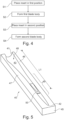
- FIG. 3 shows a mould half 40 for forming one of the half shells 32, 34.
- the mould half will be referred to hereafter for convenience as the mould.
- the mould 40 comprises a mould root end 41 and a mould distal end 45.
- the half shell is formed on a mould surface 43, herein also referred to as a primary mould surface, having a shape corresponding to the shape of the half shell 44 to be formed.
- the primary mould surface extends from the mould root end 41 to a mould tip end 42.
- the mould 40 has a leading flange 46 and a trailing edge flange 47 which extend from the mould root end 41 to the mould distal end 45.
- the primary mould surface 43 forms a recess 48 between the mould flanges 46, 47.
- one or more layers of glass-fibre fabric are placed on the primary mould surface 43 of the mould 40. These layers will later form an outer skin of the blade 18. Structural elements, including spar caps and sandwich core panels are then arranged on top of the outer fabric layers. One or more further layers of dry glass-fibre fabric are then placed over the structural elements, and will later form an inner skin of the blade.
- the glass-fibre layers are then impregnated with a resin, which is subsequently hardened to form a solid plastic material.
- a resin which is subsequently hardened to form a solid plastic material.
- Such an impregnation can be done with a vacuum assisted resin transfer moulding (VARTM) process, which is known per se, and not described closed here.
- VARTM vacuum assisted resin transfer moulding
- the primary mould surface 43 has a length L0, i.e. the same as that of the blade in Figure 2 .
- the mould shown in Figure 3 may be used to form a blade body, in the form of a half shell, for the blade in Figure 2 .
- the primary mould surface 43 comprises a portion 49 presenting a constant cross-section.
- the mould surface constant cross-section portion 49 forms part of the blade constant cross-section 21 shown in Figure 2 .
- FIG. 4 showing a block diagram depicting steps in a method according to an example.
- the method comprises placing S1 a movable insert 50 on the primary mould surface 43, in a first position.
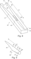
- FIG. 5 showing the insert 50 placed in the first position.
- the insert 50 is located in the mould recess 48.
- the insert 50 is placed within the constant cross-section portion 49.
- the insert 50 shortens the effective mould surface, i.e. the combined mould surface provided by the primary mould surface 43 and an insert mould surface.
- the length of the combined mould surface is L1 defined between the mould root end and an insert tip end 142.
- Figure 6 shows the insert 50 in more detail, with the insert mould surface 143.
- the insert 50 extends between a proximal end 51 facing toward the mould root end 41 and a distal end 52 facing away from the mould root end 41.
- the insert 50 presents an insert tip end 142 which forms an end of the insert mould surface 143.
- An underside 144 of the insert 50 has in this embodiment a constant cross-section.
- the shape of the cross-section of the underside 144 is substantially the same as the shape of the cross-section in the primary mould surface constant cross-section portion 49.
- the insert mould surface 142 has a cross-sectional shape which is substantially the same as the shape of the cross-section in the constant cross-section portion 49.
- the proximal end 51 has a shape which is substantially the same as the cross-sectional shape of the constant cross-section portion 49.
- the thickness of the insert 50 at the proximal end 51 may be no larger than 10 mm, preferably no larger than 5 mm.
- a filler material can be applied onto the primary mould surface 43, and adjacent to the insert proximal end 51.
- the method comprises forming S2, with the insert 50 in the first position, a first blade body having a first length L1.
- the first blade body is a shell half, which is joined with another shell half, to form a first blade B1, depicted in Figure 7 .
- the length L1 of the first blade B1 is the same as the length L1 of the combined mould surface in Figure 5 .
- the first blade B1 has a geometry which is identical with the geometry of the blade 18 shown in Figure 2 , produced by the mould without the insert 50.
- the insert 50 can be left in the mould 40 in order to manufacture further first blade bodies having the same length L1.
- the method comprises placing S3 the insert 50 on the primary mould surface 43, in a second position.
- the insert 50 is placed within the constant cross-section portion 49.
- the second position is in this example, compared to the first position, closer to the mould root end 41.
- the insert 50 further shortens the combined mould surface provided by the primary mould surface 43 and the insert mould surface 143.
- the length of the combined mould surface is L2 defined between the mould root end and the insert tip end 142.
- the method comprises forming S4, with the insert 50 in the second position, a second blade body having a second length L2.
- the second blade body is a shell half, which is joined with another shell half, to form a second blade B2, depicted in Figure 9 .
- the length L2 of the second blade B2 is the same as the length L2 of the combined mould surface in Figure 8 .
- the second blade B2 has a shorter spanwise length that the first blade B1 due to the different position of the insert 50 in the mould 40.
- the first blade B1, ( Figure 7 ), and the second blade B2 have geometries which are identical.
- the first and second blades B1, B2 have an identical aerodynamic surface between the root end 20 and the respective portions formed by the insert, the internal structure can vary therein. For example, as the second blade B2 has a shorter length it may be subjected to less loads in use (compared to the first blade B1) such that it does not require the same amount of structural material.
- the insert 50 can be left in the mould 40 in order to manufacture further second blade bodies having the same length L2.
- a number of blade variants having different blade lengths can be formed in the same mould.
- L0 Figure 2
- a movable insert 50 can be used to produce a plurality of blade variants having shorter lengths, e.g. 56 metres, 55 metres and 54 metres etc.
- variations in blade length of from anywhere between about 0.1% to about 20% can be provided, although preferably the variation in length is in the region of from about 1 % to about 10%, more preferably from about 3% to about 7%.
- the blade bodies formed with the mould may have a length within 90-100%, preferably 95-100%, of the length of the longest blade body that can be formed in the mould.
- blade bodies may be produced with lengths differing in a stepwise manner, e.g. by 100-2000 mm, or 200-1000 mm, from one blade body to another.
- blade lengths may be varied within a wind farm, from some wind turbines to others, in a manner which increases the energy output of the windfarm, as described above.
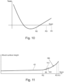
- Figure 10 shows the twist of the blade in Figure 2 along its span, moving from the root of the blade (at the left hand side of the abscissa) to the tip end of the blade (at the right hand side of the abscissa).
- blade twist is necessary as the effective flow at the blade in use comprises the rotor rotational speed and the oncoming wind speed.
- the angle of attack of a blade section also varies along the blade span.
- the blade has a twist distribution from the root to the tip.
- the tip of the blade is also "de-twisted" in order to reduce the induced drag from the tip of the blades.
- the constant cross-section portion 21 extends from a radius R2 to a radius R3.
- the twist of the blade changes, in the constant cross-section portion, linearly in the spanwise direction.
- a twist of the primary mould surface 43 ( Figure 3 ) changes, in the constant cross-section portion 49, linearly in the longitudinal direction of the primary mould surface 43.
- the lower side of the insert 50 preferably has a form which is complementary to the linearly changing twist of the primary mould surface 43.
- wind turbine blades may be bent in the flapwise direction, i.e. bent in a plane which is parallel to the longitudinal blade direction, and perpendicular to the chordwise direction. Such a bend may be referred to as a pre-bend.
- Figure 11 is a diagram with a side elevation of the primary mould surface in a further example.
- the diagram shows the primary mould surface 43 along a vertical plane in the longitudinal direction of the mould, and along the lowest part of the recess formed by the primary mould surface 43.
- an outer part of the primary mould surface 43 is curved in the longitudinal direction so as to provide a longitudinal bend on the blade bodies.
- the curvature of the primary mould surface 43 has a constant radius RB in the constant cross-section portion, between the spanwise radii R2 and R3.
- a difference, at the first position and at the second position, of the orientation of the insert 50 around a lateral axis of the primary mould surface 43 is linearly dependent on the distance between the first position and the second position.
- the underside 144 of the insert 50 has a form which is complementary to the constant curvature primary mould surface 43. More specifically, the underside 144 of the insert 50 has a longitudinal curvature with a radius which is the same as the radius RB of the constant curvature primary mould surface 43. Thereby, the combined mould surface, formed by the insert mould surface 143 and a part of the primary mould surface 43, may the altered by moving the insert 50 between any positions within the constant cross-section portion, without any special provisions needed in view of the curved primary mould surface 43.
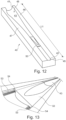
- FIG. 12 showing a mould in a further example.
- the mould 40 is not provided with a part for forming the tip of the blade bodies. Instead, the constant cross-section portion extends to the mould tip end 42.
- the mould tip end 42 coincides with the mould distal end 45.
- the insert 50 may be placed on the primary mould surface 43, at the mould tip end 42. The insert 50 may even extend past the mould tip end 42.
- Fixing the insert in the mould may be done in a variety of manners.
- placing the insert 50, in the first and second positions, or in any position along the constant cross-section portion 49 comprises fixing the insert 50 in a lateral direction of the primary mould surface 43, by means of a mechanical locking arrangement 53.
- the mechanical locking arrangement comprises in this example a track 53 extending along both opposite longitudinal edges of the primary mould surface 43.
- the tracks are in this example provided as elongated grooves 53. It is understood that in alternative embodiments, the tracks 53 could be provided as elongated ridges.
- the mechanical locking arrangement extends along the entire constant cross-section portion 49 of the primary mould surface 43, ( Figure 3 ). It is understood that the opposite longitudinal edges of the primary mould surface 43 are parallel.
- the insert 50 may be provided with engagement means for engagement with the locking arrangement.
- the insert 50 is provided with ridges 54 arranged to engage the tracks 53. As can be seen in Figure 13 , the insert 50 partly covers the locking arrangement 53.
- cover devices 55 are placed to cover parts of the locking arrangement 53 not covered by the insert 50.
- the covering devices 55 are in this example provided as elongated elements arranged to engage the respective tracks 53 of the locking arrangement. They may, in addition to covering the part of the locking arrangement not covered by the insert 50, provide a portion of the primary mould surface 43. As exemplified below, such a primary mould surface 43 portion may form at least one of opposite longitudinal edges of the primary mould surface 43.
- the locking arrangement may comprise rows of separated protrusions or recesses. Complementary recesses or protrusions, may be provided on the insert 50. This would allow the insert to be placed at a limited number of discrete locations along primary mould surface 43.
- Figure 15 and Figure 16 show how the insert 50 may be held to the mould 40 via a vacuum.
- Figure 15 is a cross-sectional view through the mould 40 and the insert 50
- Figure 16 is a plan view.
- the insert 50 is placed in the mould 40 such that the insert leading edge flange 146 is aligned with the mould leading edge flange 46, and the insert trailing edge flange 147 is aligned with the mould trailing edge flange 47.
- the gap 60 allows an under pressure to be created between the insert 50 and the mould 40 so that the insert is retained in a fixed position against the mould. It will be appreciated that the gap 60 is shown enlarged in the figures for clarity.
- a seal is provided between the mould 40 and the insert 50. Referring to Figure 16 , the following seals are provided:
- a vacuum line 64 is attached and passes through the vacuum film of seal 63.
- a vacuum pump 65 then evacuates the air under the seal 63 which will also evacuate the air from the gap 60. Compared to the ambient air pressure, the pressure in the gap 60 will be at a relatively lower pressure such that the insert 50 is 'sucked' down onto the mould 40.
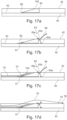
- Figure 17a to Figure 17d are schematic cross-section views along the line XVII-XVII of Figure 16 .
- Figure 17a to Figure 17d illustrate the steps taken to manufacture the wind turbine blade shell in the mould 40 with the insert 50.
- Figure 17a shows the insert 50 placed in the mould 40. As can be seen there is the gap 60 between the primary mould surface 43 and the underside of the insert 50.
- the insert 50 is sealed against the mould 40 so that it is retained firmly in position.
- a seal 62 is provided between the proximal end 51 of the insert and the primary mould surface 43 as discussed above.
- the seal 63 at the distal end of the insert comprises strips of sealing tape 63a (for example butyl rubber) and a vacuum film 63b which provides an effective seal.
- the vacuum line 64 is also shown in Figure 17b. The cavity under the vacuum film 63b is evacuated which as discussed above will force the insert 50 against the mould 40 and hold it tightly in position.
- Figure 17c shows the blade materials being laid into the mould, onto the primary mould surface 43 and the insert mould surface 143.
- the blade materials 70 comprise layers of pre-preg glass fibres and optionally sandwich core panels.
- the blade materials 70 are covered with a vacuum film 75 and the cavity under the vacuum film 75 is evacuated in order to consolidate the blade materials as is conventional in a composite fabrication operation.
- the vacuum film 75 is sealed around the periphery of the mould with sealant tape 76. Then the mould is heated in order to cure the blade materials 70.
- the insert 50 may be heated by absorbing heat from the mould. Alternatively, or in addition, the insert 50 can have inbuilt electrical elements so that the insert can have its own heating system for curing the modified tip end of the blade.
- the vacuum line 64 which is used to retain the insert 50 in position on the mould 40 can pass between the vacuum film 75 and the periphery of the mould 40. When air is evacuated from under the vacuum film 75 the vacuum film 75 will hold the insert 50 against the mould and it is not necessary to keep the vacuum pump 65 running.
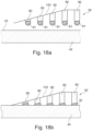
- the insert may have a shape which is complementary to the constant cross-section portion.
- Figure 16a and Figure 16b show schematically how the insert 50 can be manufactured such that it has an accurate fit with the primary mould surface 43 of the mould 40.
- the insert mould surface 143 is formed from glass fibre reinforced plastic (GFRP).
- GFRP glass fibre reinforced plastic
- Extending from an underside of the insert mould surface are a plurality of ribs 80 formed from core material.
- the ribs are formed from PET foam, but other structural core materials could be used.
- the ribs extend from the insert mould surface 143 toward the primary mould surface 43.
- the ribs 80 are fabricated such that they do not extend all the way to the primary mould surface 43.
- each rib 80 opposite the insert mould surface 143 there is a bead of uncured adhesive 81, e.g. epoxy or PUR adhesive.
- the primary mould surface 43 of the mould 40 has been treated with a release agent.
- the insert 50 is first held above the primary mould surface 43 of the mould 40 and then it is lowered such that the adhesive beads 81 make contact with the primary mould surface 43 shown in Figure 18b . This compresses and deforms the adhesive beads 81 to the shape of the primary mould surface 43.
- the insert 50 is held in the correct place on the mould 40 via clamps or the use of a jig. While the insert 50 is being held, the adhesive beads 81 will cure and thus this will provide an accurate matching shape between the insert 50 and the primary mould surface 43. Thus, the bottom of the adhesive beads 81 become the underside 144 of the insert. As the primary mould surface 43 has been treated with a release agent, once the adhesive beads 81 have cured, the insert can be lifted from the mould 40 ready for use in a blade manufacturing process. As all moulds 40 can be slightly different due to manufacturing tolerances, it is desirable to produce a bespoke insert 50 for each mould, and the use of the adhesive beads 81 provides a quick and simple solution to create an accurate alignment between the mould and the insert 50. To provide the gap 60 which allows the insert 50 to be held to the mould 40 by vacuum, grooves can simply be scored in the cured adhesive beads 81.
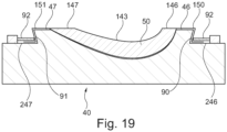
- FIG 19 shows a more detailed example of how the insert 50 can be secured to the mould 40.
- the mould 40 comprises a leading flange 46 and a trailing edge flange 47 as described above. Located below these flanges are a leading edge process flange 246 and a trailing edge process flange 247. These process flanges 246, 247 are connected to the mould flanges 46, 47 via side surfaces of the mould 90 and 91.
- the mould side surfaces extend in a substantially vertical plane. In this example, the side surfaces of the mould are inclined relative to the vertical plane.
- the inclined surface 90 is formed such that there is an acute angle between the inclined surface 90 and the process flange 246.
- the inclined surface 91 is formed such that there is an acute angle between the inclined surface 91 and the process flange 247.
- the insert 50 is fabricated with a strip 150 of GFRP which extends out from the insert leading edge flange 146, over the mould leading edge flange 46, inclined surface 90 and leading edge process flange 246.
- the strip 150 is held against the inclined surface 90 with a clamp 92 which is connected to the leading edge process flange 246.
- the insert 50 is fabricated with a strip 151 of GFRP which extends out from the insert trailing edge flange 147, over the mould trailing edge flange 47, inclined surface 91 and trailing edge process flange 247.
- the strip 151 is held against the inclined surface 91 with a clamp 92 which is connected to the trailing edge process flange 247.
- a vacuum seal (not shown) is provided between the strip 150 and the leading edge process flange 246 and between the strip 151 and the leading edge process flange 247. Vacuum seals are also provided at the proximal end and the distal end of the insert as described with reference to Figure 16 . Therefore, the insert 50 is held in place against the mould by a vacuum force and by the clamps 92.
- the strips 150 and 151 are formed from GFRP and are typically just 0.5 millimetres thick. Thus they can be elastically deformed to fit around the negative draft angles of the inclined surfaces 90 and 91.
- negative draft angle is meant that the surfaces 90 and 91 are inclined relative to the mould flanges such that the insert 50 cannot be directly lifted off the mould 40 as the strips 150 and 151 will clash with the inclined surfaces. Instead, some force has to be applied to the strips 150, 151 in order to deform them and lift the insert from the mould.
- the clamps 92 may also be in the form of bolts which connect the insert 50 to the process flanges 246, 247 of the mould 40. Using bolts is advantageous because holes in the insert 50 can be aligned with corresponding holes on the mould 40, so that the insert 50 is always located at the correct position when placed on the primary mould surface 43.
- the side surfaces of the mould 90, 91 both have a negative draft angle.
- only one of the side surfaces has a negative draft angle, and the other side surface has a zero draft or a positive draft angle.
- This arrangement will accommodate more variations in fit between the mould 40 and the insert 50.
- the principle of providing a movable insert is applicable to any suitable method of blade manufacture in a mould.
- it is applicable to blades formed as a single piece within a single mould cavity, or to blades formed from any number of sub-components which are subsequently assembled.
Landscapes
- Engineering & Computer Science (AREA)
- Mechanical Engineering (AREA)
- Chemical & Material Sciences (AREA)
- Composite Materials (AREA)
- Life Sciences & Earth Sciences (AREA)
- Sustainable Development (AREA)
- Sustainable Energy (AREA)
- Combustion & Propulsion (AREA)
- General Engineering & Computer Science (AREA)
- Wind Motors (AREA)
Claims (13)
- Procédé de fabrication de corps de pale d'éolienne, le procédé comprenant les étapes consistant à :fournir un moule (40) présentant une surface de moule allongée (43),placer un insert mobile (50) sur la surface de moule, dans une première position, former, avec l'insert dans la première position, un premier corps de pale présentant une première longueur (L1),placer l'insert (50) sur la surface de moule, dans une seconde position, etformer, avec l'insert dans la seconde position, un second corps de pale présentant une seconde longueur (L2) qui est différente de la première longueur,caractérisé en ce queune différence, à la première position et à la seconde position, de l'orientation de l'insert (50) autour d'un axe longitudinal de la surface de moule (43) est linéairement dépendante de la distance entre la première position et la seconde position.
- Procédé selon la revendication 1, dans lequel la surface de moule (43) s'étend d'une extrémité de pied de moule (41) à une extrémité de pointe de moule (42), et comprend une portion présentant une section transversale constante, dans lequel les étapes consistant à placer l'insert (50), dans les première et seconde positions, comprennent les étapes consistant à placer l'insert (50) avec une extrémité proximale (51) de celui-ci orientée vers l'extrémité de pied de moule (41), et à placer l'extrémité proximale (51) à l'intérieur de la portion à section transversale constante.
- Procédé selon la revendication 2, dans lequel l'extrémité proximale (51) présente une forme qui est sensiblement identique à la forme de section transversale de la portion à section transversale constante.
- Procédé selon l'une quelconque des revendications précédentes, dans lequel une différence, à la première position et à la seconde position, de l'orientation de l'insert (50) autour d'un axe latéral de la surface de moule (43) est linéairement dépendante de la distance entre la première position et la seconde position.
- Procédé selon l'une quelconque des revendications précédentes, dans lequel les étapes consistant à placer l'insert (50), dans les première et seconde positions, comprennent l'étape consistant à fixer l'insert (50) dans une direction latérale de la surface de moule, au moyen d'un agencement de verrouillage mécanique (53) s'étendant le long d'au moins l'un des bords longitudinaux opposés de la surface de moule.
- Procédé selon la revendication 5, dans lequel l'étape consistant à fixer l'insert (50) comprend l'étape consistant à placer l'insert (50) de manière à recouvrir partiellement l'agencement de verrouillage, dans lequel un dispositif de recouvrement (55) est placé pour recouvrir une partie de l'agencement de verrouillage non recouverte par l'insert.
- Procédé selon l'une quelconque des revendications précédentes, dans lequel l'insert (50) présente une extrémité de pointe d'insert (142) pour former une pointe des premier et second corps de pale.
- Procédé selon l'une quelconque des revendications précédentes, comprenant en outre les étapes consistant à : sélectionner les longueurs des premier et second corps de pale sur la base de longueurs requises de pales respectives pour une première éolienne et une seconde éolienne, et sélectionner les première et seconde positions pour former les premier et second corps de pale avec les longueurs sélectionnées.
- Appareil de fabrication de corps de pale d'éolienne comprenant :un moule (40), présentant une surface de moule allongée (43) s'étendant depuis une extrémité de pied de moule (41) jusqu'à une extrémité de pointe de moule (42), la surface de moule (43) comprenant une portion présentant une section transversale constante,et un insert mobile (50), l'appareil étant agencé pour permettre à l'insert d'être placé sur la surface de moule, dans une pluralité de positions le long de la direction longitudinale de la surface de moule, pour former des corps de pale présentant des longueurs respectives qui dépendent de la position d'insert le long de la direction longitudinale de la surface de moule,caractérisé en ce que,dans la portion à section transversale constante, une torsion de la surface de moule varie linéairement dans la direction longitudinale de la surface de moule.
- Appareil selon la revendication 9, dans lequel l'insert (50) comprend une extrémité proximale (51) agencée pour faire face à l'extrémité de pied de moule (41) et une extrémité distale (52) agencée pour faire face à l'opposé de l'extrémité de pied de moule, l'extrémité proximale présentant une forme qui est sensiblement identique à la forme de section transversale de la portion à section transversale constante.
- Appareil selon l'une quelconque des revendications 9-10, dans lequel au moins une partie de la surface de moule (43) est incurvée dans la direction longitudinale de manière à fournir une courbe longitudinale sur les corps de pale, la courbure de la surface de moule étant constante dans la portion à section transversale constante.
- Appareil selon l'une quelconque des revendications 9-11, dans lequel le moule (40) présente, dans la portion à section transversale constante, un agencement de verrouillage mécanique le long d'au moins l'un de bords longitudinaux opposés de la surface de moule, pour fixer l'insert (50) dans une direction latérale de la surface de moule.
- Appareil selon la revendication 12, dans lequel l'insert (50) est agencé pour recouvrir partiellement l'agencement de verrouillage, l'appareil comprenant en outre un dispositif de recouvrement (55) agencé pour recouvrir une partie de l'agencement de verrouillage non recouverte par l'insert.
Applications Claiming Priority (2)
| Application Number | Priority Date | Filing Date | Title |
|---|---|---|---|
| DKPA201870800 | 2018-12-06 | ||
| PCT/DK2019/050379 WO2020114565A1 (fr) | 2018-12-06 | 2019-12-05 | Procédé de fabrication de corps de pale d'éolienne |
Publications (3)
| Publication Number | Publication Date |
|---|---|
| EP3890936A1 EP3890936A1 (fr) | 2021-10-13 |
| EP3890936B1 true EP3890936B1 (fr) | 2023-11-01 |
| EP3890936C0 EP3890936C0 (fr) | 2023-11-01 |
Family
ID=68847916
Family Applications (1)
| Application Number | Title | Priority Date | Filing Date |
|---|---|---|---|
| EP19817954.1A Active EP3890936B1 (fr) | 2018-12-06 | 2019-12-05 | Procédé de fabrication de corps de pale d'éolienne |
Country Status (4)
| Country | Link |
|---|---|
| US (1) | US11951659B2 (fr) |
| EP (1) | EP3890936B1 (fr) |
| ES (1) | ES2962630T3 (fr) |
| WO (1) | WO2020114565A1 (fr) |
Families Citing this family (2)
| Publication number | Priority date | Publication date | Assignee | Title |
|---|---|---|---|---|
| EP3922429A1 (fr) * | 2020-06-12 | 2021-12-15 | Siemens Gamesa Renewable Energy A/S | Moule adapté pour la production d'au moins une partie d'une pale d'éolienne |
| JP7279102B2 (ja) * | 2021-03-25 | 2023-05-22 | 三菱重工業株式会社 | 繊維強化複合材成形方法および繊維強化複合材成形装置 |
Citations (1)
| Publication number | Priority date | Publication date | Assignee | Title |
|---|---|---|---|---|
| DE102014001445A1 (de) * | 2014-01-31 | 2015-08-20 | Windnovation Engineering Solutions Gmbh | Vorrichtung zur Herstellung von Rotorblattschalen |
Family Cites Families (5)
| Publication number | Priority date | Publication date | Assignee | Title |
|---|---|---|---|---|
| US9140235B2 (en) * | 2012-08-22 | 2015-09-22 | General Electric Company | Variable length blade tip molds, tip assemblies and methods for manufacturing the same |
| DE102012223703A1 (de) * | 2012-12-19 | 2014-06-26 | Sgl Carbon Se | Variable Formvorrichtung zur Herstellung einer Halbschale für ein Rotorblatt für eine Windenergieanlage |
| DE102012223810A1 (de) * | 2012-12-19 | 2014-06-26 | Sgl Carbon Se | Variable Formvorrichtung zur Herstellung einer Halbschale für ein Rotorblatt für eine Windenergieanlage |
| CN103350467A (zh) | 2013-06-19 | 2013-10-16 | 广东明阳风电产业集团有限公司 | 一种能制造多种风机叶片模具及其制作方法 |
| EP3380293B1 (fr) | 2015-11-25 | 2021-09-22 | Vestas Wind Systems A/S | Procédé et appareil de fabrication d'un corps de lame de turbine éolienne |
-
2019
- 2019-12-05 WO PCT/DK2019/050379 patent/WO2020114565A1/fr unknown
- 2019-12-05 US US17/299,450 patent/US11951659B2/en active Active
- 2019-12-05 EP EP19817954.1A patent/EP3890936B1/fr active Active
- 2019-12-05 ES ES19817954T patent/ES2962630T3/es active Active
Patent Citations (1)
| Publication number | Priority date | Publication date | Assignee | Title |
|---|---|---|---|---|
| DE102014001445A1 (de) * | 2014-01-31 | 2015-08-20 | Windnovation Engineering Solutions Gmbh | Vorrichtung zur Herstellung von Rotorblattschalen |
Also Published As
| Publication number | Publication date |
|---|---|
| US11951659B2 (en) | 2024-04-09 |
| ES2962630T3 (es) | 2024-03-20 |
| EP3890936C0 (fr) | 2023-11-01 |
| US20220055320A1 (en) | 2022-02-24 |
| WO2020114565A1 (fr) | 2020-06-11 |
| EP3890936A1 (fr) | 2021-10-13 |
Similar Documents
| Publication | Publication Date | Title |
|---|---|---|
| CN110131095B (zh) | 叶片翼梁帽的非平面轮廓剖面的拉挤纤维复合材料条带 | |
| CN109989877B (zh) | 风轮机叶片翼梁帽的波纹轮廓的拉挤纤维复合材料条带 | |
| US10316817B2 (en) | Wind turbine blade and an associated manufacturing method | |
| CA3031137A1 (fr) | Pale d'eolienne avec segment de dos plat et procede associe | |
| CN108495739B (zh) | 用于制造风轮机叶片本体的方法与设备 | |
| EP3890936B1 (fr) | Procédé de fabrication de corps de pale d'éolienne | |
| US11667087B2 (en) | Distance member for connecting wind turbine blade shear webs | |
| WO2020231828A1 (fr) | Extension de bord longitudinal | |
| US11220079B2 (en) | System and method for manufacturing a wind turbine blade | |
| US20240293982A1 (en) | A guide member for guiding a shear web of wind turbine blade | |
| US20230078908A1 (en) | Method for manufacturing a wind turbine blade using an air heating assembly | |
| EP2716904B1 (fr) | procédé de fabrication d'un capuchon de longeron composite pour pale de rotor d'éolienne | |
| CN108698353B (zh) | 模制风轮机叶片的壳部分的方法 | |
| WO2018224106A1 (fr) | Pales d'éolienne modulaires | |
| EP4234192A1 (fr) | Procédé de fabrication de préformes de pales d'éoliennes à géométries complexes | |
| BR112019011264B1 (pt) | Sistema e método para fabricação de uma lâmina de turbina eólica |
Legal Events
| Date | Code | Title | Description |
|---|---|---|---|
| STAA | Information on the status of an ep patent application or granted ep patent |
Free format text: STATUS: UNKNOWN |
|
| STAA | Information on the status of an ep patent application or granted ep patent |
Free format text: STATUS: THE INTERNATIONAL PUBLICATION HAS BEEN MADE |
|
| PUAI | Public reference made under article 153(3) epc to a published international application that has entered the european phase |
Free format text: ORIGINAL CODE: 0009012 |
|
| STAA | Information on the status of an ep patent application or granted ep patent |
Free format text: STATUS: REQUEST FOR EXAMINATION WAS MADE |
|
| 17P | Request for examination filed |
Effective date: 20210611 |
|
| AK | Designated contracting states |
Kind code of ref document: A1 Designated state(s): AL AT BE BG CH CY CZ DE DK EE ES FI FR GB GR HR HU IE IS IT LI LT LU LV MC MK MT NL NO PL PT RO RS SE SI SK SM TR |
|
| DAV | Request for validation of the european patent (deleted) | ||
| DAX | Request for extension of the european patent (deleted) | ||
| GRAP | Despatch of communication of intention to grant a patent |
Free format text: ORIGINAL CODE: EPIDOSNIGR1 |
|
| STAA | Information on the status of an ep patent application or granted ep patent |
Free format text: STATUS: GRANT OF PATENT IS INTENDED |
|
| GRAJ | Information related to disapproval of communication of intention to grant by the applicant or resumption of examination proceedings by the epo deleted |
Free format text: ORIGINAL CODE: EPIDOSDIGR1 |
|
| RIC1 | Information provided on ipc code assigned before grant |
Ipc: B29L 31/08 20060101ALI20230413BHEP Ipc: B29C 70/30 20060101ALI20230413BHEP Ipc: B29C 70/44 20060101ALI20230413BHEP Ipc: B29D 99/00 20100101ALI20230413BHEP Ipc: B29C 33/30 20060101AFI20230413BHEP |
|
| GRAP | Despatch of communication of intention to grant a patent |
Free format text: ORIGINAL CODE: EPIDOSNIGR1 |
|
| INTG | Intention to grant announced |
Effective date: 20230508 |
|
| INTG | Intention to grant announced |
Effective date: 20230526 |
|
| GRAS | Grant fee paid |
Free format text: ORIGINAL CODE: EPIDOSNIGR3 |
|
| GRAA | (expected) grant |
Free format text: ORIGINAL CODE: 0009210 |
|
| STAA | Information on the status of an ep patent application or granted ep patent |
Free format text: STATUS: THE PATENT HAS BEEN GRANTED |
|
| AK | Designated contracting states |
Kind code of ref document: B1 Designated state(s): AL AT BE BG CH CY CZ DE DK EE ES FI FR GB GR HR HU IE IS IT LI LT LU LV MC MK MT NL NO PL PT RO RS SE SI SK SM TR |
|
| REG | Reference to a national code |
Ref country code: GB Ref legal event code: FG4D |
|
| REG | Reference to a national code |
Ref country code: CH Ref legal event code: EP |
|
| REG | Reference to a national code |
Ref country code: DE Ref legal event code: R096 Ref document number: 602019040704 Country of ref document: DE |
|
| REG | Reference to a national code |
Ref country code: IE Ref legal event code: FG4D |
|
| U01 | Request for unitary effect filed |
Effective date: 20231109 |
|
| U07 | Unitary effect registered |
Designated state(s): AT BE BG DE DK EE FI FR IT LT LU LV MT NL PT SE SI Effective date: 20231116 |
|
| PGFP | Annual fee paid to national office [announced via postgrant information from national office to epo] |
Ref country code: GB Payment date: 20231219 Year of fee payment: 5 |
|
| U20 | Renewal fee paid [unitary effect] |
Year of fee payment: 5 Effective date: 20231226 |
|
| REG | Reference to a national code |
Ref country code: ES Ref legal event code: FG2A Ref document number: 2962630 Country of ref document: ES Kind code of ref document: T3 Effective date: 20240320 |
|
| PG25 | Lapsed in a contracting state [announced via postgrant information from national office to epo] |
Ref country code: GR Free format text: LAPSE BECAUSE OF FAILURE TO SUBMIT A TRANSLATION OF THE DESCRIPTION OR TO PAY THE FEE WITHIN THE PRESCRIBED TIME-LIMIT Effective date: 20240202 |
|
| PG25 | Lapsed in a contracting state [announced via postgrant information from national office to epo] |
Ref country code: IS Free format text: LAPSE BECAUSE OF FAILURE TO SUBMIT A TRANSLATION OF THE DESCRIPTION OR TO PAY THE FEE WITHIN THE PRESCRIBED TIME-LIMIT Effective date: 20240301 |
|
| PGFP | Annual fee paid to national office [announced via postgrant information from national office to epo] |
Ref country code: ES Payment date: 20240118 Year of fee payment: 5 |
|
| PG25 | Lapsed in a contracting state [announced via postgrant information from national office to epo] |
Ref country code: IS Free format text: LAPSE BECAUSE OF FAILURE TO SUBMIT A TRANSLATION OF THE DESCRIPTION OR TO PAY THE FEE WITHIN THE PRESCRIBED TIME-LIMIT Effective date: 20240301 Ref country code: GR Free format text: LAPSE BECAUSE OF FAILURE TO SUBMIT A TRANSLATION OF THE DESCRIPTION OR TO PAY THE FEE WITHIN THE PRESCRIBED TIME-LIMIT Effective date: 20240202 |
|
| PG25 | Lapsed in a contracting state [announced via postgrant information from national office to epo] |
Ref country code: RS Free format text: LAPSE BECAUSE OF FAILURE TO SUBMIT A TRANSLATION OF THE DESCRIPTION OR TO PAY THE FEE WITHIN THE PRESCRIBED TIME-LIMIT Effective date: 20231101 Ref country code: PL Free format text: LAPSE BECAUSE OF FAILURE TO SUBMIT A TRANSLATION OF THE DESCRIPTION OR TO PAY THE FEE WITHIN THE PRESCRIBED TIME-LIMIT Effective date: 20231101 Ref country code: NO Free format text: LAPSE BECAUSE OF FAILURE TO SUBMIT A TRANSLATION OF THE DESCRIPTION OR TO PAY THE FEE WITHIN THE PRESCRIBED TIME-LIMIT Effective date: 20240201 Ref country code: HR Free format text: LAPSE BECAUSE OF FAILURE TO SUBMIT A TRANSLATION OF THE DESCRIPTION OR TO PAY THE FEE WITHIN THE PRESCRIBED TIME-LIMIT Effective date: 20231101 |
|
| PG25 | Lapsed in a contracting state [announced via postgrant information from national office to epo] |
Ref country code: CZ Free format text: LAPSE BECAUSE OF FAILURE TO SUBMIT A TRANSLATION OF THE DESCRIPTION OR TO PAY THE FEE WITHIN THE PRESCRIBED TIME-LIMIT Effective date: 20231101 |
|
| PG25 | Lapsed in a contracting state [announced via postgrant information from national office to epo] |
Ref country code: SK Free format text: LAPSE BECAUSE OF FAILURE TO SUBMIT A TRANSLATION OF THE DESCRIPTION OR TO PAY THE FEE WITHIN THE PRESCRIBED TIME-LIMIT Effective date: 20231101 |
|
| PG25 | Lapsed in a contracting state [announced via postgrant information from national office to epo] |
Ref country code: SM Free format text: LAPSE BECAUSE OF FAILURE TO SUBMIT A TRANSLATION OF THE DESCRIPTION OR TO PAY THE FEE WITHIN THE PRESCRIBED TIME-LIMIT Effective date: 20231101 Ref country code: SK Free format text: LAPSE BECAUSE OF FAILURE TO SUBMIT A TRANSLATION OF THE DESCRIPTION OR TO PAY THE FEE WITHIN THE PRESCRIBED TIME-LIMIT Effective date: 20231101 Ref country code: CZ Free format text: LAPSE BECAUSE OF FAILURE TO SUBMIT A TRANSLATION OF THE DESCRIPTION OR TO PAY THE FEE WITHIN THE PRESCRIBED TIME-LIMIT Effective date: 20231101 |
|
| REG | Reference to a national code |
Ref country code: CH Ref legal event code: PL |
|
| REG | Reference to a national code |
Ref country code: DE Ref legal event code: R097 Ref document number: 602019040704 Country of ref document: DE |
|
| PG25 | Lapsed in a contracting state [announced via postgrant information from national office to epo] |
Ref country code: MC Free format text: LAPSE BECAUSE OF FAILURE TO SUBMIT A TRANSLATION OF THE DESCRIPTION OR TO PAY THE FEE WITHIN THE PRESCRIBED TIME-LIMIT Effective date: 20231101 |
|
| PG25 | Lapsed in a contracting state [announced via postgrant information from national office to epo] |
Ref country code: MC Free format text: LAPSE BECAUSE OF FAILURE TO SUBMIT A TRANSLATION OF THE DESCRIPTION OR TO PAY THE FEE WITHIN THE PRESCRIBED TIME-LIMIT Effective date: 20231101 |
|
| PLBE | No opposition filed within time limit |
Free format text: ORIGINAL CODE: 0009261 |
|
| STAA | Information on the status of an ep patent application or granted ep patent |
Free format text: STATUS: NO OPPOSITION FILED WITHIN TIME LIMIT |