EP3890925B1 - Hydraulic tensioner and method of tensioning - Google Patents
Hydraulic tensioner and method of tensioning Download PDFInfo
- Publication number
- EP3890925B1 EP3890925B1 EP19818274.3A EP19818274A EP3890925B1 EP 3890925 B1 EP3890925 B1 EP 3890925B1 EP 19818274 A EP19818274 A EP 19818274A EP 3890925 B1 EP3890925 B1 EP 3890925B1
- Authority
- EP
- European Patent Office
- Prior art keywords
- stud
- tensioner
- threaded
- piston
- sleeve
- Prior art date
- Legal status (The legal status is an assumption and is not a legal conclusion. Google has not performed a legal analysis and makes no representation as to the accuracy of the status listed.)
- Active
Links
Images




Classifications
-
- B—PERFORMING OPERATIONS; TRANSPORTING
- B25—HAND TOOLS; PORTABLE POWER-DRIVEN TOOLS; MANIPULATORS
- B25B—TOOLS OR BENCH DEVICES NOT OTHERWISE PROVIDED FOR, FOR FASTENING, CONNECTING, DISENGAGING, OR HOLDING
- B25B29/00—Accessories
- B25B29/02—Bolt tensioners
-
- B—PERFORMING OPERATIONS; TRANSPORTING
- B23—MACHINE TOOLS; METAL-WORKING NOT OTHERWISE PROVIDED FOR
- B23P—METAL-WORKING NOT OTHERWISE PROVIDED FOR; COMBINED OPERATIONS; UNIVERSAL MACHINE TOOLS
- B23P19/00—Machines for simply fitting together or separating metal parts or objects, or metal and non-metal parts, whether or not involving some deformation; Tools or devices therefor so far as not provided for in other classes
- B23P19/04—Machines for simply fitting together or separating metal parts or objects, or metal and non-metal parts, whether or not involving some deformation; Tools or devices therefor so far as not provided for in other classes for assembling or disassembling parts
- B23P19/06—Screw or nut setting or loosening machines
- B23P19/067—Bolt tensioners
Definitions
- This invention relates to a hydraulic tensioner and a method of tensioning using such a tensioner.
- Hydraulic tensioners are well known; we describe such a tensioner in our earlier United Kingdom Patent number GB2 457 138 B . They generally comprise a body and a piston, with a pressure space defined therebetween such that introduction of (e.g.) hydraulic fluid into the pressure space forces the piston and body apart. If the piston is coupled to the work piece to be tensioned (e.g. though a threaded stud), then this can be used to tension the work piece.
- US4150477A describes a hydraulic tensioner with a base, a piston mounted for sliding motion relative to the base, the base and the piston defining a pressure space there between and being arranged to be urged apart along an axis upon introduction of a fluid into the pressure space, the tensioner further comprising a threaded stud having an exterior thread.
- a hydraulic tensioner comprising:
- the internal bore will comprise a wider section having a larger diameter than the internally threaded portion.
- the drive mechanism can then comprise a sleeve member in the wider section passing from the second end to the internally threaded portion, with the sleeve being coupled to the stud so as to transmit rotation of the sleeve to the stud.
- the drive mechanism may comprise a coupling between the sleeve and the stud arranged so as to permit movement of the stud relative to the sleeve along the axis but to fix the stud and the sleeve relative to each other rotationally.
- the coupling may be a splined coupling, comprising complementary splines on the sleeve (typically internally) and on a member fixed to the stud.
- the drive mechanism may comprise a drive member at the second end, having an engagement means for being driven by a user, rotation of the engagement means causing rotation of the sleeve.
- the engagement means will comprise a protrusion or recess to engage with a tool by means of which the drive member can be rotated.
- the piston may also be provided with location for a tool to rotate the piston. This will allow the piston to be rotated so as to close up any gap that might be present once the stud is fully engaged in the item to be tensioned.
- the threaded component may be the piston, or a part thereof.
- the threaded component may comprise an insert received within and which bears against the piston.
- the threaded component may comprise a reaction nut which is threaded onto the stud and which is received within a recess in the piston, or which bears against an end surface of the piston.
- the stud may have a length measured along the axis, which may be at most the same as a length of the internal bore along the same axis.
- the stud may have a retracted position where it is entirely received within the internal bore.
- the stud may also have an extended position, when it extends from the internal bore. Typically, at least 50%, if not 80% of a length of the stud will extend from the internal bore in the extended position.
- the base and the piston may define a second chamber therebetween, which may be provided with a connection for a gas (such as air). Whilst a fluid can fill the (main) pressure space in order to apply tension, the second chamber can be used to return the tensioner to its original position (i.e. zero stroke).
- the connection may comprise a one-way valve, which allows has (such as air) to enter the second chamber but not escape. This has been found to function as a spring (a so-called "air spring").
- a method of tensioning a work piece having a threaded bore comprising:
- the method may also comprise the step of rotating the piston once the stud has engaged the threaded bore of the work piece, so that the tensioner abuts a surface of the work piece adjacent to the threaded bore of the work piece.
- the work piece may comprise a plurality of threaded bores.
- the method may comprise providing a plurality of the threaded bores with tensioners in accordance with the first aspect of the invention.
- the method may also comprise providing those threaded bores which have not been provided with tensioners with threaded tension retaining members, such as bolts with heads, or threaded studs with nuts.
- the method may comprise retaining the tension applied to the workspace with the tension retaining members, for example by rotating the bolts or nuts such that the heads or nuts are adjacent to a surface of the workpiece.
- the method may also comprise, after the tension has been applied, returning the piston to a zero stroke position by pressurising the second chamber with a gas, such as air.
- the method may then comprise rotating the piston so as to bring the tensioner closer to the work piece.
- the method can further comprise using the drive mechanism to retract the stud from the workpiece, and then typically removing the tensioner from the work piece.
- the work piece may comprise a shrink disc.
- a hydraulic tensioner in accordance with a first embodiment of the invention is shown in Figures 1 and 2 of the accompanying drawings.
- the tensioner 1 comprises a body 2 and a piston 3.
- the piston 3 can more relative to the body 2, and there is a pressure space 4 defined between the piston 3 and the body 2.
- the pressure space 4 is provided with a fluid connection 5 by means of which fluid - typically hydraulic fluid - can be introduced into the pressure space 4. Doing so forces the piston 3 and body 2 apart along axis 8, such that (as shown in Figures 1 and 2 ), the piston 3 will move upwards relative to the body 2.
- a second pressure space 15 is formed between the body 2 and piston 3, which is provided with a connection 16 for gas (e.g. air).
- gas e.g. air
- this connection 16 is provided as a one-way valve, such that air is introduced into the space as the second pressure space 15 increases in size, but cannot escape when the second pressure space 15 decreases in size.
- the second pressure space acts in a similar manner as a spring, tending to counteract the force generated by the introduction of hydraulic fluid into the (main) pressure space 4.
- the force generated by the second pressure space 15 is significantly lower than that generated by the introduction of hydraulic fluid into the main pressure space 4, but once that force is released, it tends to return the piston 3 to its original position relative to the body 2 (which is shown in Figures 1 and 2 ).
- the piston 3 is provided with an internal bore 6 having an internally threaded part 7 at a first, bottom end and a wider (in terms of diameter) part 9 at the second, top end, all coaxial with axis 8. Within this bore 6 is provided a threaded stud 10, the external thread of which engages the internal thread of the internally threaded part 7 of the internal bore 6.
- the stud has a head 11 fixed to it.
- a cylindrical sleeve 12 This is coupled to a drive member 13 at the top end, but runs the length of the wider portion 9.
- the sleeve 12 is internally splined, the head 11 having complementary splines.
- the drive member 13 has a square recess 14 (quarter inch / 0.635 cm) for attachment of a tool.
- the splined connection of the head 11 and the sleeve 12 allows linear motion of the head 11 and the stud 10 along the axis 8, but does not allow the head 11 and the stud 10 to rotate relative to the sleeve 12.
- the tensioner 1 is brought to the work piece 20 (here, a shrink disc), which has a plurality of threaded bores 21.
- the tensioner 1 is positioned so that the bottom face of the tensioner 1 is on the surface of the work piece, with the stud 10 over one of the threaded bores 21.
- the work piece comprises an overhang 22, so there is not a great deal of space available vertically over the threaded bores 21.
- a tensioner 1 would be provided for every other threaded bore 21; the remaining threaded bores would be provided with threaded nuts with hexagonal heads.
- a ratchet drive tool 23 has engaged recess 14 in drive member 13.
- the tool 23 rotates the drive member 13, which rotates sleeve 12, which in turn rotates the head 11 fixed to stud 10. This causes the stud 10 to rotate.
- the stud 10 is engaged with threaded portion 7, the stud 10 is drive along axis 8 out of the bore 6, as shown in Figure 6 .
- the thread of the stud 10 engages that of the threaded bore 21.
- the piston 3 is provided with drive holes 17 by means of which the piston 3 can be rotated. By inserting a tommy bar 24 into one of these holes 17, the piston can be rotated so that any gap 25 is closed up as shown in Figure 7 .
- the pressure space 4 can then be filled with pressurised hydraulic fluid, so as to drive the piston 3 upwards with respect to body 2. This has the effect of pulling the stud 10 up in the threaded bore 21, thus tensioning the work piece 20.
- the tensioner 1 can be pressurised so as to produce its maximum stroke, which is demonstrated by a thin red line (not shown) appearing at the top edge of the piston 3.
- the tommy bar 24 can again be used in hole 17 to rotate the tensioner 1 so that it is flush against the surface of work piece 20, as shown in Figure 10 .
- the ratchet tool 23 can then be reintroduce into drive member 13 as shown in Figure 11 , and used to drive the stud in the opposite direction as previously, in order to retract the stud 10 from threaded bore 21, as shown in Figure 11 .
- the tensioner 1 can be removed from workpiece 20.
- the work piece 20 has been tensioned; the nuts can be tightened with a torque wrench if desired.
- the threaded portion 57 is formed in an insert 80 separate from the piston 53.
- This insert 80 is a sliding fit within the piston 53 and has a flange 81 at the second end which bears against the piston 53.
- the internal bore 56 is therefore formed within the insert 80, which then contains the sleeve 62.
- a third embodiment of the invention can be seen in Figure 14 of the invention equivalent features to those of the first embodiment have been given corresponding reference numerals, raised by 100.
- reaction nut 120 rather than the piston or an insert carrying the internally threaded portion, this is carried on a reaction nut 120.
- the internal bore 106 is within the piston 103 once more, and has a tapered recess 121 for the reaction nut 120.
- Reaction nut 120 is threaded onto the stud 110, so as to have the force from piston 103 transferred to it by the reaction nut 120.
- a separate load retaining nut 123 is provided, which can be run down the stud 110 once load has been applied to it.
- the third embodiment otherwise functions as the first embodiment, with the sleeve 112 working within the internal bore 106 in the piston 103.
- a fourth embodiment of the invention can be seen in Figure 14 of the invention equivalent features to those of the first embodiment have been given corresponding reference numerals, raised by 150.
- the piston 153 again provides the internally threaded portion 157 and is threaded onto stud 160.
- the internal bore 156 is formed in multiple components: the piston 153 and a floating member 170.
- the sleeve 162 therefore sits within these two components. This is advantageous because it results in less wear on the pressure seals 171 and less effort for the operator as they only need to rotate the piston 153 against one set of seals 171 rather than against 3 or 4 as in the first embodiment.
Landscapes
- Engineering & Computer Science (AREA)
- Mechanical Engineering (AREA)
- Hand Tools For Fitting Together And Separating, Or Other Hand Tools (AREA)
Description
- This invention relates to a hydraulic tensioner and a method of tensioning using such a tensioner.
- Hydraulic tensioners are well known; we describe such a tensioner in our earlier United Kingdom Patent number
GB2 457 138 B US4150477A describes a hydraulic tensioner with a base, a piston mounted for sliding motion relative to the base, the base and the piston defining a pressure space there between and being arranged to be urged apart along an axis upon introduction of a fluid into the pressure space, the tensioner further comprising a threaded stud having an exterior thread. - Many applications for hydraulic tensioners have limited space in which the tensioner can be used. In particular, height (that is, distance above the tensioner in the direction in which the tensioner pulls) can be limited significantly. Furthermore, for applications with limited access - for example, in the nacelle of wind turbines - it is often desired to take as few items as possible with a user making use of the tensioner. Previous attempts at solving this problem have generally used multiple components that must be assembled in the application space, which is undesirable.
- Prior art single unit tools have generally involved a captive stud, but the length of the stud protruding from the tensioner in such a case has meant that such tensioners have been sufficiently long not be to acceptable in some applications.
- As such, it would be desirable to provide a hydraulic tensioner with limited height requirements, and that required as few discrete items as possible.
- According to a first aspect of the invention, there is provided a hydraulic tensioner, comprising:
- a base;
- a piston mounted for sliding motion relative to the base,
- the base and the piston defining a pressure space therebetween and being arranged to be urged apart along an axis upon introduction of a fluid into the pressure space, the tensioner having an internal bore along the axis having first and second ends along the axis and comprising a threaded component having an internally threaded portion at the first end and coupled to the piston;
- the tensioner further comprising:
- a threaded stud having an exterior thread which engages the internally threaded portion of the threaded component; and
- a drive mechanism arranged to transmit rotational motion from the second end of the internal bore to the threaded stud;
the tensioner being arranged such that rotational motion applied to the drive mechanism at the second end causes rotation of the stud relative to the threaded component, with the engagement of the exterior thread of the stud and the internal thread of the threaded component causing the stud to move along the axis as it rotates. - This allows for a reduced-height tensioner that can be provided as a single unit, which is useful in confined spaces and in situations where it is desired to make use of the minimum number of units.
- Typically, the internal bore will comprise a wider section having a larger diameter than the internally threaded portion. The drive mechanism can then comprise a sleeve member in the wider section passing from the second end to the internally threaded portion, with the sleeve being coupled to the stud so as to transmit rotation of the sleeve to the stud.
- The drive mechanism may comprise a coupling between the sleeve and the stud arranged so as to permit movement of the stud relative to the sleeve along the axis but to fix the stud and the sleeve relative to each other rotationally. The coupling may be a splined coupling, comprising complementary splines on the sleeve (typically internally) and on a member fixed to the stud.
- The drive mechanism may comprise a drive member at the second end, having an engagement means for being driven by a user, rotation of the engagement means causing rotation of the sleeve. Typically, the engagement means will comprise a protrusion or recess to engage with a tool by means of which the drive member can be rotated.
- The piston may also be provided with location for a tool to rotate the piston. This will allow the piston to be rotated so as to close up any gap that might be present once the stud is fully engaged in the item to be tensioned.
- The threaded component may be the piston, or a part thereof. Alternatively, the threaded component may comprise an insert received within and which bears against the piston. In a further alternative, the threaded component may comprise a reaction nut which is threaded onto the stud and which is received within a recess in the piston, or which bears against an end surface of the piston.
- The stud may have a length measured along the axis, which may be at most the same as a length of the internal bore along the same axis. The stud may have a retracted position where it is entirely received within the internal bore. The stud may also have an extended position, when it extends from the internal bore. Typically, at least 50%, if not 80% of a length of the stud will extend from the internal bore in the extended position.
- The base and the piston may define a second chamber therebetween, which may be provided with a connection for a gas (such as air). Whilst a fluid can fill the (main) pressure space in order to apply tension, the second chamber can be used to return the tensioner to its original position (i.e. zero stroke). The connection may comprise a one-way valve, which allows has (such as air) to enter the second chamber but not escape. This has been found to function as a spring (a so-called "air spring").
- According to a second aspect of the invention, there is provided a method of tensioning a work piece having a threaded bore, comprising:
- positioning the tensioner of the first aspect of the invention adjacent to the bore;
- using the drive mechanism to rotate the stud such that it extends from the tensioner and engages the threaded bore of the work piece; and
- introducing fluid into the pressure space in order to force the base and piston apart, so as to apply tension to the work piece.
- The method may also comprise the step of rotating the piston once the stud has engaged the threaded bore of the work piece, so that the tensioner abuts a surface of the work piece adjacent to the threaded bore of the work piece.
- The work piece may comprise a plurality of threaded bores. The method may comprise providing a plurality of the threaded bores with tensioners in accordance with the first aspect of the invention. The method may also comprise providing those threaded bores which have not been provided with tensioners with threaded tension retaining members, such as bolts with heads, or threaded studs with nuts. The method may comprise retaining the tension applied to the workspace with the tension retaining members, for example by rotating the bolts or nuts such that the heads or nuts are adjacent to a surface of the workpiece.
- The method may also comprise, after the tension has been applied, returning the piston to a zero stroke position by pressurising the second chamber with a gas, such as air. The method may then comprise rotating the piston so as to bring the tensioner closer to the work piece.
- The method can further comprise using the drive mechanism to retract the stud from the workpiece, and then typically removing the tensioner from the work piece.
- Typically, the work piece may comprise a shrink disc.
- There now follows, by way of example only, description of embodiments of the invention, described with reference to the accompanying drawings, in which:
-
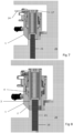
Figure 1 shows a cross section through a hydraulic tensioner in accordance with a first embodiment of the invention, with its stud in a retracted state; -
Figure 2 shows a cross section through the tensioner ofFigure 1 , with its stud in an extended state; -
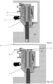
Figures 3 to 12 show sequentially the tensioner ofFigure 1 being used to tension a shrink disc; -
Figure 13 shows a cross section through a tensioner in accordance with a second embodiment of the invention; -
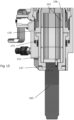
Figure 14 shows a cross section through a tensioner in accordance with a third embodiment of the invention; and -
Figure 15 shows a cross section through a tensioner in accordance with a fourth embodiment of the invention. - A hydraulic tensioner in accordance with a first embodiment of the invention is shown in
Figures 1 and2 of the accompanying drawings. Thetensioner 1 comprises abody 2 and apiston 3. Thepiston 3 can more relative to thebody 2, and there is apressure space 4 defined between thepiston 3 and thebody 2. Thepressure space 4 is provided with afluid connection 5 by means of which fluid - typically hydraulic fluid - can be introduced into thepressure space 4. Doing so forces thepiston 3 andbody 2 apart alongaxis 8, such that (as shown inFigures 1 and2 ), thepiston 3 will move upwards relative to thebody 2. - A
second pressure space 15 is formed between thebody 2 andpiston 3, which is provided with aconnection 16 for gas (e.g. air). As explained in our United KingdomPatent GB 2 457 138B connection 16 is provided as a one-way valve, such that air is introduced into the space as thesecond pressure space 15 increases in size, but cannot escape when thesecond pressure space 15 decreases in size. As such, the second pressure space acts in a similar manner as a spring, tending to counteract the force generated by the introduction of hydraulic fluid into the (main)pressure space 4. The force generated by thesecond pressure space 15 is significantly lower than that generated by the introduction of hydraulic fluid into themain pressure space 4, but once that force is released, it tends to return thepiston 3 to its original position relative to the body 2 (which is shown inFigures 1 and2 ). - The
piston 3 is provided with aninternal bore 6 having an internally threadedpart 7 at a first, bottom end and a wider (in terms of diameter)part 9 at the second, top end, all coaxial withaxis 8. Within thisbore 6 is provided a threadedstud 10, the external thread of which engages the internal thread of the internally threadedpart 7 of theinternal bore 6. The stud has ahead 11 fixed to it. - Within the
wider part 9 of theinternal bore 6, there is provided acylindrical sleeve 12. This is coupled to adrive member 13 at the top end, but runs the length of thewider portion 9. Thesleeve 12 is internally splined, thehead 11 having complementary splines. Thedrive member 13 has a square recess 14 (quarter inch / 0.635 cm) for attachment of a tool. - As such, rotation of the
drive member 13 at the top end will cause rotation of thesleeve 12. The internal splines of thesleeve 12 will cause thestud 10 to rotate. The threaded engagement of thestud 10 in the threadedportion 7 will then cause thestud 10 to move along the axis, from the retracted position shown inFigure 1 where thestud 10 is entirely within thebore 6, to the extended position shown inFigure 2 where thestud 10 is largely extended out of thebore 6. As thestud 10 moves along theaxis 8, the splined connection of thehead 11 and thesleeve 12 allows linear motion of thehead 11 and thestud 10 along theaxis 8, but does not allow thehead 11 and thestud 10 to rotate relative to thesleeve 12. - The operation of this tensioner in tensioning (in this example) a shrink disc can be demonstrated with reference to
Figures 3 to 12 of the accompanying drawings, which sequentially show the tensioner's use. - In
Figure 3 , thetensioner 1 is brought to the work piece 20 (here, a shrink disc), which has a plurality of threaded bores 21. As shown inFigure 4 , thetensioner 1 is positioned so that the bottom face of thetensioner 1 is on the surface of the work piece, with thestud 10 over one of the threaded bores 21. As can be seen, the work piece comprises anoverhang 22, so there is not a great deal of space available vertically over the threaded bores 21. Typically, atensioner 1 would be provided for every other threaded bore 21; the remaining threaded bores would be provided with threaded nuts with hexagonal heads. - In
Figure 5 , aratchet drive tool 23 has engagedrecess 14 indrive member 13. Thetool 23 rotates thedrive member 13, which rotatessleeve 12, which in turn rotates thehead 11 fixed tostud 10. This causes thestud 10 to rotate. Because thestud 10 is engaged with threadedportion 7, thestud 10 is drive alongaxis 8 out of thebore 6, as shown inFigure 6 . The thread of thestud 10 engages that of the threaded bore 21. - Once the
stud 10 has reached its maximum travel, there will potentially be a gap of up to one pitch of thestud 10 thread between thetensioner 1 and theworkpiece 20. In order to close this up, thepiston 3 is provided with drive holes 17 by means of which thepiston 3 can be rotated. By inserting atommy bar 24 into one of theseholes 17, the piston can be rotated so that anygap 25 is closed up as shown inFigure 7 . - The
pressure space 4 can then be filled with pressurised hydraulic fluid, so as to drive thepiston 3 upwards with respect tobody 2. This has the effect of pulling thestud 10 up in the threaded bore 21, thus tensioning thework piece 20. Thetensioner 1 can be pressurised so as to produce its maximum stroke, which is demonstrated by a thin red line (not shown) appearing at the top edge of thepiston 3. - When the appropriate loading is reached, the nuts (not shown) in the other threaded bores (not shown) would be run down so as to capture the tension created.
- The hydraulic pressure in
space 4 can then be released, and the air captured insecond pressure space 15 will cause thepiston 3 to retract back to its original position as shown inFigure 9 . This will lift thetensioner 1 off the surface of thework piece 20. - If there is now insufficient space between the
overhang 22 to engageratchet tool 23, thetommy bar 24 can again be used inhole 17 to rotate thetensioner 1 so that it is flush against the surface ofwork piece 20, as shown inFigure 10 . - The
ratchet tool 23 can then be reintroduce intodrive member 13 as shown inFigure 11 , and used to drive the stud in the opposite direction as previously, in order to retract thestud 10 from threaded bore 21, as shown inFigure 11 . - Once
stud 10 is retracted as shown inFigure 12 , thetensioner 1 can be removed fromworkpiece 20. Thework piece 20 has been tensioned; the nuts can be tightened with a torque wrench if desired. - Thus, a single unit tensioner that has limited height requirements is provided.
- A second embodiment of the invention is shown in
Figure 13 of the accompanying drawings; equivalent features to those of the first embodiment have been given corresponding reference numerals, raised by 50. - In this embodiment, the threaded
portion 57 is formed in aninsert 80 separate from thepiston 53. Thisinsert 80 is a sliding fit within thepiston 53 and has a flange 81 at the second end which bears against thepiston 53. Thus, as thepiston 53 is forced apart from thebody 52, the piston will react against the flange 81, transmitting force from thepiston 53 through theinsert 80 to the threadedstud 60. Theinternal bore 56 is therefore formed within theinsert 80, which then contains thesleeve 62. This embodiment otherwise functions as described above with respect to the first embodiment of the invention. - A third embodiment of the invention can be seen in
Figure 14 of the invention equivalent features to those of the first embodiment have been given corresponding reference numerals, raised by 100. - In this embodiment, rather than the piston or an insert carrying the internally threaded portion, this is carried on a
reaction nut 120. Theinternal bore 106 is within thepiston 103 once more, and has a taperedrecess 121 for thereaction nut 120. As such, when the piston is urged upwards (as shown inFigure 14 ) by the introduction of hydraulic pressure, the piston will forcereaction nut 120 upwards.Reaction nut 120 is threaded onto thestud 110, so as to have the force frompiston 103 transferred to it by thereaction nut 120. A separateload retaining nut 123 is provided, which can be run down thestud 110 once load has been applied to it. - Again, the third embodiment otherwise functions as the first embodiment, with the
sleeve 112 working within theinternal bore 106 in thepiston 103. - A fourth embodiment of the invention can be seen in
Figure 14 of the invention equivalent features to those of the first embodiment have been given corresponding reference numerals, raised by 150. - In this embodiment, the
piston 153 again provides the internally threadedportion 157 and is threaded ontostud 160. However, theinternal bore 156 is formed in multiple components: thepiston 153 and a floatingmember 170. Thesleeve 162 therefore sits within these two components. This is advantageous because it results in less wear on the pressure seals 171 and less effort for the operator as they only need to rotate thepiston 153 against one set ofseals 171 rather than against 3 or 4 as in the first embodiment. - Otherwise, this embodiment functions as described in the first embodiment.
Claims (15)
- A hydraulic tensioner, comprising:• a base (2);• a piston (3) mounted for sliding motion relative to the base (2),the base (2) and the piston (3) defining a pressure space (4) therebetween and being arranged to be urged apart along an axis (8) upon introduction of a fluid into the pressure space (4), the tensioner having an internal bore (6) along the axis (8) having first and second ends along the axis (8) and comprising a threaded component having an internally threaded portion (7) at the first end and coupled to the piston (3);the tensioner further comprising:• a threaded stud (10) having an exterior thread which engages the internally threaded portion (7) of the threaded component; and• a drive mechanism (12, 13) arranged to transmit rotational motion from the second end of the internal bore (6) to the threaded stud (10);
the tensioner being arranged such that rotational motion applied to the drive mechanism (12, 13) at the second end causes rotation of the stud (10) relative to the threaded component, with the engagement of the exterior thread of the stud (10) and the internal thread (7) of the threaded component causing the stud (10) to move along the axis (8) as it rotates. - The tensioner of claim 1, in which the internal bore (6) comprises a wider section having a larger diameter than the internally threaded portion (7), the drive mechanism comprising a sleeve member (12) in the wider section passing from the second end to the internally threaded portion (7), with the sleeve (12) being coupled to the stud (10) so as to transmit rotation of the sleeve (12) to the stud (13).
- The tensioner of claim 2, in which the drive mechanism (12, 13) comprises a coupling between the sleeve (12) and the stud (10) arranged so as to permit movement of the stud relative to the sleeve along the axis but to fix the stud (10) and the sleeve (12) relative to each other rotationally.
- The tensioner of claim 3, in which the coupling is a splined coupling, comprising complementary splines on the sleeve (12) and on a member (11) fixed to the stud (10).
- The tensioner of any preceding claim, in which the drive mechanism comprises a drive member (12) at the second end, having an engagement means (14) for being driven by a user, rotation of the engagement means (14) causing rotation of the sleeve (12).
- The tensioner of any preceding claim, in which the piston (3) is provided with location (17) for a tool (24) to rotate the piston (3).
- The tensioner of any preceding claim, in which the stud (10) has a retracted position where it is entirely received within the internal bore (6).
- The tensioner of any preceding claim, in which threaded component is the piston (3), or a part thereof.
- The tensioner of any of claims 1 to 7, in which the threaded component comprises an insert (80) received within and which bears against the piston (53).
- The tensioner of any of claims 1 to 7, in which the threaded component comprises a reaction nut (120) which is threaded onto the stud (110) and which is received within a recess in the piston (103), or which bears against an end surface of the piston (103).
- A method of tensioning a work piece (20) having a threaded bore (21), comprising:• positioning a tensioner (1) in accordance with any preceding claim adjacent to the bore (21);• using the drive mechanism (12, 13) to rotate the stud (10) such that it extends from the tensioner (1) and engages the threaded bore (21) of the work piece (20); and• introducing fluid into the pressure space (4) in order to force the base (2) and piston (3) apart, so as to apply tension to the work piece (20).
- The method of claim 11, comprising the step of rotating the piston (3) once the stud (10) has engaged the threaded bore (21) of the work piece (20), so that the tensioner (1) abuts a surface of the work piece (20) adjacent to the threaded bore (21) of the work piece.
- The method of claim 11 or claim 12, in which the work piece (20) comprises a plurality of threaded bores (21), the method comprising providing a plurality of the threaded bores (21) with tensioners (1) in accordance with any of claims 1 to 10.
- The method of claim 13, comprising providing those threaded bores which have not been provided with tensioners (1) with threaded tension retaining members.
- The method of any of claims 11 to 14, in which the work piece (20) comprises a shrink disc.
Applications Claiming Priority (2)
| Application Number | Priority Date | Filing Date | Title |
|---|---|---|---|
| GB1819775.6A GB2579578A (en) | 2018-12-04 | 2018-12-04 | Hydraulic tensioner and method of tensioning |
| PCT/IB2019/060426 WO2020115673A1 (en) | 2018-12-04 | 2019-12-04 | Hydraulic tensioner and method of tensioning |
Publications (3)
| Publication Number | Publication Date |
|---|---|
| EP3890925A1 EP3890925A1 (en) | 2021-10-13 |
| EP3890925C0 EP3890925C0 (en) | 2024-05-15 |
| EP3890925B1 true EP3890925B1 (en) | 2024-05-15 |
Family
ID=65030228
Family Applications (1)
| Application Number | Title | Priority Date | Filing Date |
|---|---|---|---|
| EP19818274.3A Active EP3890925B1 (en) | 2018-12-04 | 2019-12-04 | Hydraulic tensioner and method of tensioning |
Country Status (7)
| Country | Link |
|---|---|
| US (1) | US11911883B2 (en) |
| EP (1) | EP3890925B1 (en) |
| CN (1) | CN114025920B (en) |
| ES (1) | ES2982185T3 (en) |
| GB (1) | GB2579578A (en) |
| PL (1) | PL3890925T3 (en) |
| WO (1) | WO2020115673A1 (en) |
Families Citing this family (2)
| Publication number | Priority date | Publication date | Assignee | Title |
|---|---|---|---|---|
| WO2021062224A1 (en) * | 2019-09-26 | 2021-04-01 | Enerpac Tool Group Corp. | Tensioning device |
| EP4459136A1 (en) * | 2023-05-05 | 2024-11-06 | Hitachi Energy Ltd | Tensioner device |
Family Cites Families (19)
| Publication number | Priority date | Publication date | Assignee | Title |
|---|---|---|---|---|
| US3158052A (en) * | 1961-10-04 | 1964-11-24 | Biach Ind | Tensioning apparatus |
| DE1300472B (en) * | 1966-03-18 | 1969-07-31 | Licentia Gmbh | Hydraulic device for pre-tensioning and loosening a screw connection |
| GB1157220A (en) * | 1966-09-14 | 1969-07-02 | Moeller & Neumann Verwalt Ges | Tie Rod Clamp Device for Clamping Co-operating Components |
| US4150477A (en) * | 1977-09-21 | 1979-04-24 | Exxon Production Research Company | Pre-loading joint flanges |
| US4535656A (en) * | 1981-03-12 | 1985-08-20 | Orban Joseph N | Integral tensioner assembly for tensioning, inserting and removing a stud |
| RU2015871C1 (en) * | 1990-04-02 | 1994-07-15 | Сумский физико-технологический институт | Hydraulic nut runner |
| DE4142990C2 (en) * | 1991-12-24 | 1998-03-19 | Westfalia Nukleartechnik Gmbh | Screwdriver for screwing the lid of pressure vessels u. Like., In particular of reactor pressure vessels |
| DE4201324C2 (en) * | 1992-01-20 | 1999-02-04 | Westfalia Nukleartechnik Gmbh | Screw tensioning device |
| EP1448338B1 (en) * | 2001-11-30 | 2009-12-23 | Westinghouse Electric Company LLC | Method of closing a pressure vessel |
| GB2427667B (en) * | 2005-06-25 | 2009-04-29 | Tentec Ltd | Thread-Engaging members for tensioners |
| FR2905460B1 (en) * | 2006-09-01 | 2009-08-07 | Skf Ab | METHOD AND DEVICE FOR CONTROLLING HYDRAULIC CLAMPING OF ONE OR MORE BOLTS. |
| GB2457138B (en) | 2008-02-07 | 2012-06-20 | Tentec Ltd | Bolt tensioners |
| GB2474887B (en) * | 2009-10-30 | 2013-12-04 | Stats Uk Ltd | Device and method for pre-tensioning a coupling |
| US9188146B1 (en) * | 2010-08-05 | 2015-11-17 | Riverhawk Company | Hydraulic rod tensioning system |
| GB2492140B (en) * | 2011-06-23 | 2015-11-18 | Tentec Ltd | Tensioner for threaded members with containment component |
| US10500685B2 (en) * | 2014-02-06 | 2019-12-10 | Tentec Limited | Tensioner |
| FR3034821B1 (en) * | 2015-04-09 | 2017-09-08 | Skf Ab | VOLTAGE DEVICE FOR PRE-STRESSING AN ASSEMBLY USING A THREADED ROD |
| DE102016205086A1 (en) * | 2016-03-29 | 2017-10-05 | Aktiebolaget Skf | Rod clamping device and assembly method for such a device on a rod |
| GB2556099A (en) * | 2016-11-21 | 2018-05-23 | Caterpillar Energy Solutions Gmbh | Screw tensioning device |
-
2018
- 2018-12-04 GB GB1819775.6A patent/GB2579578A/en not_active Withdrawn
-
2019
- 2019-12-04 PL PL19818274.3T patent/PL3890925T3/en unknown
- 2019-12-04 EP EP19818274.3A patent/EP3890925B1/en active Active
- 2019-12-04 WO PCT/IB2019/060426 patent/WO2020115673A1/en not_active Ceased
- 2019-12-04 ES ES19818274T patent/ES2982185T3/en active Active
- 2019-12-04 CN CN201980089620.8A patent/CN114025920B/en active Active
- 2019-12-04 US US17/299,677 patent/US11911883B2/en active Active
Also Published As
| Publication number | Publication date |
|---|---|
| PL3890925T3 (en) | 2024-12-09 |
| CN114025920B (en) | 2023-12-29 |
| EP3890925A1 (en) | 2021-10-13 |
| EP3890925C0 (en) | 2024-05-15 |
| US20220032433A1 (en) | 2022-02-03 |
| GB201819775D0 (en) | 2019-01-23 |
| US11911883B2 (en) | 2024-02-27 |
| CN114025920A (en) | 2022-02-08 |
| ES2982185T3 (en) | 2024-10-15 |
| WO2020115673A1 (en) | 2020-06-11 |
| GB2579578A (en) | 2020-07-01 |
Similar Documents
| Publication | Publication Date | Title |
|---|---|---|
| US11407088B2 (en) | Multifunction socket tool | |
| EP1755832B1 (en) | Improvements to hydraulic tensioning jacks | |
| DE60006972T2 (en) | HYDRAULIC SCISSORS | |
| EP1108900B2 (en) | Fluid operated tool for elongating and relaxing a threaded connector | |
| AU2008205440B2 (en) | Fluid-operated torque wrench for and method of tightening or loosening fasteners | |
| EP2143521A1 (en) | A multi jackbolt tensioner including tamper resistant jackbolts | |
| AU2020101459A4 (en) | Telescoping boom wear pad improvements | |
| US20150240571A1 (en) | Connection Assembly | |
| US11911883B2 (en) | Hydraulic tensioner and method of tensioning | |
| EP3205454B1 (en) | Assembly tool, its use and a method of securing a threaded insert | |
| US9261126B2 (en) | Rivet bolt in combination with an attachment and process for making same | |
| CN104895954A (en) | Torque-limiting return stop device | |
| US11660680B2 (en) | Quick-release tool connecting rod | |
| EP3302879B1 (en) | Apparatus for tightening threaded fasteners | |
| US10226856B2 (en) | Apparatus for tightening threaded fasteners | |
| US11268547B2 (en) | Hydraulically powered rotary actuator | |
| DE202016106681U1 (en) | Assembly tool for attaching a threaded insert | |
| WO2026030794A1 (en) | Hydraulic tensioning tool | |
| US10967553B2 (en) | Pin cam deflector nut | |
| EP1531027A1 (en) | Clamping device and method of clamping of workpieces, tools, molds or devices | |
| US3083586A (en) | Rifle nut | |
| WO2023140874A1 (en) | Apparatus for tightening threaded fasteners |
Legal Events
| Date | Code | Title | Description |
|---|---|---|---|
| STAA | Information on the status of an ep patent application or granted ep patent |
Free format text: STATUS: UNKNOWN |
|
| STAA | Information on the status of an ep patent application or granted ep patent |
Free format text: STATUS: THE INTERNATIONAL PUBLICATION HAS BEEN MADE |
|
| PUAI | Public reference made under article 153(3) epc to a published international application that has entered the european phase |
Free format text: ORIGINAL CODE: 0009012 |
|
| STAA | Information on the status of an ep patent application or granted ep patent |
Free format text: STATUS: REQUEST FOR EXAMINATION WAS MADE |
|
| 17P | Request for examination filed |
Effective date: 20210630 |
|
| AK | Designated contracting states |
Kind code of ref document: A1 Designated state(s): AL AT BE BG CH CY CZ DE DK EE ES FI FR GB GR HR HU IE IS IT LI LT LU LV MC MK MT NL NO PL PT RO RS SE SI SK SM TR |
|
| DAV | Request for validation of the european patent (deleted) | ||
| DAX | Request for extension of the european patent (deleted) | ||
| GRAP | Despatch of communication of intention to grant a patent |
Free format text: ORIGINAL CODE: EPIDOSNIGR1 |
|
| STAA | Information on the status of an ep patent application or granted ep patent |
Free format text: STATUS: GRANT OF PATENT IS INTENDED |
|
| INTG | Intention to grant announced |
Effective date: 20230523 |
|
| GRAS | Grant fee paid |
Free format text: ORIGINAL CODE: EPIDOSNIGR3 |
|
| GRAA | (expected) grant |
Free format text: ORIGINAL CODE: 0009210 |
|
| STAA | Information on the status of an ep patent application or granted ep patent |
Free format text: STATUS: THE PATENT HAS BEEN GRANTED |
|
| AK | Designated contracting states |
Kind code of ref document: B1 Designated state(s): AL AT BE BG CH CY CZ DE DK EE ES FI FR GB GR HR HU IE IS IT LI LT LU LV MC MK MT NL NO PL PT RO RS SE SI SK SM TR |
|
| REG | Reference to a national code |
Ref country code: CH Ref legal event code: EP |
|
| REG | Reference to a national code |
Ref country code: IE Ref legal event code: FG4D |
|
| REG | Reference to a national code |
Ref country code: DE Ref legal event code: R096 Ref document number: 602019052348 Country of ref document: DE |
|
| U01 | Request for unitary effect filed |
Effective date: 20240604 |
|
| U07 | Unitary effect registered |
Designated state(s): AT BE BG DE DK EE FI FR IT LT LU LV MT NL PT SE SI Effective date: 20240613 |
|
| PG25 | Lapsed in a contracting state [announced via postgrant information from national office to epo] |
Ref country code: IS Free format text: LAPSE BECAUSE OF FAILURE TO SUBMIT A TRANSLATION OF THE DESCRIPTION OR TO PAY THE FEE WITHIN THE PRESCRIBED TIME-LIMIT Effective date: 20240915 |
|
| PG25 | Lapsed in a contracting state [announced via postgrant information from national office to epo] |
Ref country code: HR Free format text: LAPSE BECAUSE OF FAILURE TO SUBMIT A TRANSLATION OF THE DESCRIPTION OR TO PAY THE FEE WITHIN THE PRESCRIBED TIME-LIMIT Effective date: 20240515 |
|
| PG25 | Lapsed in a contracting state [announced via postgrant information from national office to epo] |
Ref country code: GR Free format text: LAPSE BECAUSE OF FAILURE TO SUBMIT A TRANSLATION OF THE DESCRIPTION OR TO PAY THE FEE WITHIN THE PRESCRIBED TIME-LIMIT Effective date: 20240816 |
|
| REG | Reference to a national code |
Ref country code: ES Ref legal event code: FG2A Ref document number: 2982185 Country of ref document: ES Kind code of ref document: T3 Effective date: 20241015 |
|
| PG25 | Lapsed in a contracting state [announced via postgrant information from national office to epo] |
Ref country code: NO Free format text: LAPSE BECAUSE OF FAILURE TO SUBMIT A TRANSLATION OF THE DESCRIPTION OR TO PAY THE FEE WITHIN THE PRESCRIBED TIME-LIMIT Effective date: 20240815 Ref country code: IS Free format text: LAPSE BECAUSE OF FAILURE TO SUBMIT A TRANSLATION OF THE DESCRIPTION OR TO PAY THE FEE WITHIN THE PRESCRIBED TIME-LIMIT Effective date: 20240915 Ref country code: HR Free format text: LAPSE BECAUSE OF FAILURE TO SUBMIT A TRANSLATION OF THE DESCRIPTION OR TO PAY THE FEE WITHIN THE PRESCRIBED TIME-LIMIT Effective date: 20240515 Ref country code: GR Free format text: LAPSE BECAUSE OF FAILURE TO SUBMIT A TRANSLATION OF THE DESCRIPTION OR TO PAY THE FEE WITHIN THE PRESCRIBED TIME-LIMIT Effective date: 20240816 Ref country code: RS Free format text: LAPSE BECAUSE OF FAILURE TO SUBMIT A TRANSLATION OF THE DESCRIPTION OR TO PAY THE FEE WITHIN THE PRESCRIBED TIME-LIMIT Effective date: 20240815 |
|
| U20 | Renewal fee for the european patent with unitary effect paid |
Year of fee payment: 6 Effective date: 20241022 |
|
| PG25 | Lapsed in a contracting state [announced via postgrant information from national office to epo] |
Ref country code: CZ Free format text: LAPSE BECAUSE OF FAILURE TO SUBMIT A TRANSLATION OF THE DESCRIPTION OR TO PAY THE FEE WITHIN THE PRESCRIBED TIME-LIMIT Effective date: 20240515 |
|
| PG25 | Lapsed in a contracting state [announced via postgrant information from national office to epo] |
Ref country code: SK Free format text: LAPSE BECAUSE OF FAILURE TO SUBMIT A TRANSLATION OF THE DESCRIPTION OR TO PAY THE FEE WITHIN THE PRESCRIBED TIME-LIMIT Effective date: 20240515 Ref country code: RO Free format text: LAPSE BECAUSE OF FAILURE TO SUBMIT A TRANSLATION OF THE DESCRIPTION OR TO PAY THE FEE WITHIN THE PRESCRIBED TIME-LIMIT Effective date: 20240515 |
|
| PG25 | Lapsed in a contracting state [announced via postgrant information from national office to epo] |
Ref country code: SM Free format text: LAPSE BECAUSE OF FAILURE TO SUBMIT A TRANSLATION OF THE DESCRIPTION OR TO PAY THE FEE WITHIN THE PRESCRIBED TIME-LIMIT Effective date: 20240515 |
|
| PG25 | Lapsed in a contracting state [announced via postgrant information from national office to epo] |
Ref country code: SM Free format text: LAPSE BECAUSE OF FAILURE TO SUBMIT A TRANSLATION OF THE DESCRIPTION OR TO PAY THE FEE WITHIN THE PRESCRIBED TIME-LIMIT Effective date: 20240515 Ref country code: SK Free format text: LAPSE BECAUSE OF FAILURE TO SUBMIT A TRANSLATION OF THE DESCRIPTION OR TO PAY THE FEE WITHIN THE PRESCRIBED TIME-LIMIT Effective date: 20240515 Ref country code: RO Free format text: LAPSE BECAUSE OF FAILURE TO SUBMIT A TRANSLATION OF THE DESCRIPTION OR TO PAY THE FEE WITHIN THE PRESCRIBED TIME-LIMIT Effective date: 20240515 Ref country code: CZ Free format text: LAPSE BECAUSE OF FAILURE TO SUBMIT A TRANSLATION OF THE DESCRIPTION OR TO PAY THE FEE WITHIN THE PRESCRIBED TIME-LIMIT Effective date: 20240515 |
|
| REG | Reference to a national code |
Ref country code: DE Ref legal event code: R097 Ref document number: 602019052348 Country of ref document: DE |
|
| PLBE | No opposition filed within time limit |
Free format text: ORIGINAL CODE: 0009261 |
|
| STAA | Information on the status of an ep patent application or granted ep patent |
Free format text: STATUS: NO OPPOSITION FILED WITHIN TIME LIMIT |
|
| 26N | No opposition filed |
Effective date: 20250218 |
|
| PG25 | Lapsed in a contracting state [announced via postgrant information from national office to epo] |
Ref country code: MC Free format text: LAPSE BECAUSE OF FAILURE TO SUBMIT A TRANSLATION OF THE DESCRIPTION OR TO PAY THE FEE WITHIN THE PRESCRIBED TIME-LIMIT Effective date: 20240515 |
|
| REG | Reference to a national code |
Ref country code: CH Ref legal event code: PL |
|
| PG25 | Lapsed in a contracting state [announced via postgrant information from national office to epo] |
Ref country code: CH Free format text: LAPSE BECAUSE OF NON-PAYMENT OF DUE FEES Effective date: 20241231 |
|
| PG25 | Lapsed in a contracting state [announced via postgrant information from national office to epo] |
Ref country code: IE Free format text: LAPSE BECAUSE OF NON-PAYMENT OF DUE FEES Effective date: 20241204 |
|
| PGFP | Annual fee paid to national office [announced via postgrant information from national office to epo] |
Ref country code: GB Payment date: 20251209 Year of fee payment: 7 |
|
| U20 | Renewal fee for the european patent with unitary effect paid |
Year of fee payment: 7 Effective date: 20251209 |
|
| PGFP | Annual fee paid to national office [announced via postgrant information from national office to epo] |
Ref country code: PL Payment date: 20251203 Year of fee payment: 7 |
|
| PG25 | Lapsed in a contracting state [announced via postgrant information from national office to epo] |
Ref country code: CY Free format text: LAPSE BECAUSE OF FAILURE TO SUBMIT A TRANSLATION OF THE DESCRIPTION OR TO PAY THE FEE WITHIN THE PRESCRIBED TIME-LIMIT; INVALID AB INITIO Effective date: 20191204 |
|
| PGFP | Annual fee paid to national office [announced via postgrant information from national office to epo] |
Ref country code: ES Payment date: 20260122 Year of fee payment: 7 |