EP3302879B1 - Apparatus for tightening threaded fasteners - Google Patents
Apparatus for tightening threaded fasteners Download PDFInfo
- Publication number
- EP3302879B1 EP3302879B1 EP16728536.0A EP16728536A EP3302879B1 EP 3302879 B1 EP3302879 B1 EP 3302879B1 EP 16728536 A EP16728536 A EP 16728536A EP 3302879 B1 EP3302879 B1 EP 3302879B1
- Authority
- EP
- European Patent Office
- Prior art keywords
- drive
- torque tool
- ratchet
- plate
- drive plate
- Prior art date
- Legal status (The legal status is an assumption and is not a legal conclusion. Google has not performed a legal analysis and makes no representation as to the accuracy of the status listed.)
- Active
Links
- 230000008878 coupling Effects 0.000 description 3
- 238000010168 coupling process Methods 0.000 description 3
- 238000005859 coupling reaction Methods 0.000 description 3
- 125000006850 spacer group Chemical group 0.000 description 3
- 238000005452 bending Methods 0.000 description 2
- 238000006243 chemical reaction Methods 0.000 description 2
- 238000010276 construction Methods 0.000 description 2
- 238000005336 cracking Methods 0.000 description 2
- 230000001815 facial effect Effects 0.000 description 2
- 230000000712 assembly Effects 0.000 description 1
- 238000000429 assembly Methods 0.000 description 1
- 230000006835 compression Effects 0.000 description 1
- 238000007906 compression Methods 0.000 description 1
Images

Classifications
-
- B—PERFORMING OPERATIONS; TRANSPORTING
- B25—HAND TOOLS; PORTABLE POWER-DRIVEN TOOLS; MANIPULATORS
- B25B—TOOLS OR BENCH DEVICES NOT OTHERWISE PROVIDED FOR, FOR FASTENING, CONNECTING, DISENGAGING OR HOLDING
- B25B21/00—Portable power-driven screw or nut setting or loosening tools; Attachments for drilling apparatus serving the same purpose
- B25B21/004—Portable power-driven screw or nut setting or loosening tools; Attachments for drilling apparatus serving the same purpose of the ratchet type
- B25B21/005—Portable power-driven screw or nut setting or loosening tools; Attachments for drilling apparatus serving the same purpose of the ratchet type driven by a radially acting hydraulic or pneumatic piston
Definitions
- a hydraulic torque wrench of the prior art including an actuator and a ratchet linkage.
- a hydraulic torque wrench is disclosed in US 4 794 826 A , US 5 450 773 A and US 2004/0159191 A1 while US 2006/0254393 A1 , US 2004/0089106 A1 und WO 97/26155 A2 show a manually driven ratchet.
- the tool shown in US 2004/0159191 A1 may also be manually driven.
- Such actuators may include one or more hydraulic cylinders and pistons.
- a free end of the actuator's piston pivotally connects to a drive lever inside the linkage.
- a drive lever As the piston moves reciprocally, it pushes this drive lever back and forth.
- a ratchet mechanism formed between the drive lever and a socket causes the socket to rotate and apply torque to the threaded fastener disposed in the socket.
- the apparatus minimizes volume and mass of the tool. Only one drive plate is necessary which is tapered from a first end to a second end.
- side plates of the link drive means are tapered from a first end to a second end.
- Such geometry minimizes the width of portions of the link drive means making the second end, adjacent the threaded fastener engagement means, substantially thinner than the first end, adjacent the piston engagement means.
- Higher torque values are transferred in a smaller enclosure via only two parts.
- no drive and/or reaction pawl is necessary as the teeth of the drive plate and the ratchet drive achieve full facial engagement.
- the design of the connection coupling is backlash-free, maximizes tool safety, minimizes risk of failures/fatigue from wear, bending, scuffing and cracking, and is suitable for changing forces.
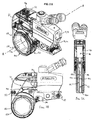
- FIGs. 1A-1D show perspective, front, side and back views of a low clearance face tooth ratchet assembly 100 for a hydraulic torque tool 1 having a cylinder-piston means 10 and a link drive means 50.
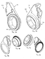
- FIGs. 2A-2C show perspective, side and front views of internal components of link drive means 50 of hydraulic torque tool 1 having low clearance face tooth ratchet assembly 100.
- Face tooth ratchet assembly 100 which includes a drive plate 110 having piston engagement means 112 at a first end 111 and a machined face gear 116 with radial serrations 117 at a second end 115.
- Face tooth ratchet assembly 100 also includes a ratchet drive 120 having a machined face gear 122 with corresponding radial serrations 123 at a first end 121 and a threaded fastener engagement means 126 at a second end 125.
- Face tooth ratchet assembly 100 is formed between and moves within a first and a second side plate 51 and 52 of link drive means 50 held rigidly apart by a first, a second a third and a fourth spacer 53, 54, 55 and 56.
- FIGs. 2A-2C indicate that drive plate 110 is reciprocatingly driven by a first and a second hydraulic piston 11 and 12 in a first and a second cylinder 13 and 14 (not shown in detail) in advance and retract strokes.
- Drive plate 110 oscillates axially about a turning force axis A.
- the advance stroke the corresponding teeth 117 and 123 of drive plate 110 and ratchet drive 120 engage under load from a wave spring 130 to tighten or loosen the threaded fastener.
- Wave spring 130 offers similar force and deflection as ordinary coil/compression springs yet fits in the tight radial and axial space of tool 1.
- Wave spring 130 is formed between drive plate 110 and side plate 52. During the retract stroke corresponding teeth 117 and 123 of drive plate 110 and ratchet drive 120 disengage and glide past each other.
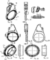
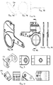
- FIGs. 3-10 show various views and more detail of components of low clearance face tooth ratchet assembly 100 and/or torque tool 1.
- connection coupling is backlash-free, maximizes tool safety, minimizes risk of failures/fatigue from wear, bending, scuffing and cracking, and is suitable for changing forces.
- the figures show face tooth ratchet link assembly 100 for use in low clearance hydraulic tools but may be adapted for use in square drive tools and links for use with both such tools powered either electrically, hydraulically, manually or pneumatically.
Description
- Often industrial bolting applications include threaded fasteners with limited clearance and/or accessibility issues. To tighten and loosen such fasteners, operators may use a hydraulic torque wrench of the prior art including an actuator and a ratchet linkage. Such a hydraulic torque wrench is disclosed in
US 4 794 826 A ,US 5 450 773 A andUS 2004/0159191 A1 whileUS 2006/0254393 A1 ,US 2004/0089106 A1 undWO 97/26155 A2 US 2004/0159191 A1 may also be manually driven. These two components may be modular so they can be coupled and decoupled depending on their desired use. Such actuators may include one or more hydraulic cylinders and pistons. With the actuator installed on the linkage, a free end of the actuator's piston pivotally connects to a drive lever inside the linkage. As the piston moves reciprocally, it pushes this drive lever back and forth. In turn, a ratchet mechanism formed between the drive lever and a socket causes the socket to rotate and apply torque to the threaded fastener disposed in the socket. - Although the operation of such torque wrenches is effective, existing torque wrenches in the art have similar designs for the ratchet linkage. Such linkages have side plates that sandwich internal components of the linkage, and spacers can be used between the plates. The socket installs in between these plates and remains exposed through openings in the plates. This socket is formed between the threaded fastener to be turned and the internal drive lever and ratchet mechanism, which is held between the side plates so it can be turned. Other internal and external components may be found on or in such limited clearance tools.
- Although common in the industry, this form of construction for limited clearance hydraulic torque wrenches of the prior art has limitations. Such torque wrench construction increases the overall width of the wrench and/or depth of the socket, which may limit the usefulness of the wrench in some situations. In some circumstances, an obstruction or feature may lie in close proximity to the object to be closed, such as a flange. This can lead to a reduced height and/or depth clearance between the object, nut, and exposed end of the bolt or bolt head that can limit access of a conventional limited clearance hydraulic torque wrench.
- Accordingly, what is needed in a hydraulic torque wrench capable of use in tight clearances to improve access of the wrench to nuts and increase the wrench's usefulness in the field.
- The invention is disclosed in the independent claim 1.
- Advantageously the apparatus minimizes volume and mass of the tool. Only one drive plate is necessary which is tapered from a first end to a second end. According to the invention, side plates of the link drive means are tapered from a first end to a second end. Such geometry minimizes the width of portions of the link drive means making the second end, adjacent the threaded fastener engagement means, substantially thinner than the first end, adjacent the piston engagement means. Higher torque values are transferred in a smaller enclosure via only two parts. Notably no drive and/or reaction pawl is necessary as the teeth of the drive plate and the ratchet drive achieve full facial engagement. The design of the connection coupling is backlash-free, maximizes tool safety, minimizes risk of failures/fatigue from wear, bending, scuffing and cracking, and is suitable for changing forces.
- Further features of the invention are set out in claims 2 to 4 appended hereto. The invention may be described by way of example only with reference to the accompanying drawings, of which:
-
FIGs. 1A-1D show perspective, front, side and back views of a hydraulic torque wrench having a low clearance face tooth ratchet assembly according to the present invention; -
FIGs. 2A-2C show perspective, side and front views of internal components of the link drive means of the hydraulic torque wrench having the low clearance face tooth ratchet assembly according to the present invention; -
FIGs. 3A-3B show perspective views of the low clearance face tooth ratchet assembly according to the present invention; -
FIGs. 4A-4D show perspective views of a drive plate and a ratchet drive of the low clearance face tooth ratchet assembly according to the present invention; -
FIGs. 5A-5F show perspective, front, detailed, side and back views of the drive plate of the low clearance face tooth ratchet assembly according to the present invention; -
FIGs. 6A-6D show perspective, front, side and cross-sectional views of the ratchet drive of the low clearance face tooth ratchet assembly according to the present invention; -
FIGs. 7A-7D show perspective, front and side views of a wave spring of the hydraulic torque wrench having the low clearance face tooth ratchet assembly according to the present invention; -
FIGs. 8A-8D show perspective, back, cross-sectional and side views of a side plate of the hydraulic torque wrench having the low clearance face tooth ratchet assembly according to the present invention; and -
FIGs. 9-10 show various views of examples of spacers of the hydraulic torque wrench having the low clearance face tooth ratchet assembly according to the present invention. -
FIGs. 1A-1D show perspective, front, side and back views of a low clearance facetooth ratchet assembly 100 for a hydraulic torque tool 1 having a cylinder-piston means 10 and a link drive means 50. -
FIGs. 2A-2C show perspective, side and front views of internal components of link drive means 50 of hydraulic torque tool 1 having low clearance facetooth ratchet assembly 100. Facetooth ratchet assembly 100 which includes adrive plate 110 having piston engagement means 112 at a first end 111 and a machinedface gear 116 withradial serrations 117 at asecond end 115. Facetooth ratchet assembly 100 also includes aratchet drive 120 having a machinedface gear 122 with correspondingradial serrations 123 at afirst end 121 and a threaded fastener engagement means 126 at asecond end 125. Facetooth ratchet assembly 100 is formed between and moves within a first and asecond side plate 51 and 52 of link drive means 50 held rigidly apart by a first, a second a third and afourth spacer -
FIGs. 2A-2C indicate thatdrive plate 110 is reciprocatingly driven by a first and a second hydraulic piston 11 and 12 in a first and a second cylinder 13 and 14 (not shown in detail) in advance and retract strokes.Drive plate 110 oscillates axially about a turning force axis A. During the advance stroke thecorresponding teeth drive plate 110 andratchet drive 120 engage under load from awave spring 130 to tighten or loosen the threaded fastener.Wave spring 130 offers similar force and deflection as ordinary coil/compression springs yet fits in the tight radial and axial space of tool 1.Wave spring 130 is formed betweendrive plate 110 andside plate 52. During the retractstroke corresponding teeth drive plate 110 and ratchet drive 120 disengage and glide past each other. - During the advance
stroke corresponding teeth drive plate 110 andratchet drive 120 nonrotatably engage relative to each other. Transmitted torque is proportional to the circumferential force, which is maximized compared with ratchet assemblies of the prior art. The angular surfaces of the teeth transmit a large portion of the circumferential force with positive locking. Tensioning media, such as, for example, disk (wave) springs, apply the required axial force to lock the teeth into torque transfer engagement. The teeth mesh around a ring and the torque capacity of the teeth increases with their diameter, arranged to accommodate the threaded fastener. Generally tapered, asymmetrical teeth are used with variable profile angles. The coupling is defined by the groove count, the outer diameter of the cylindrical feature, the bottom angle of the grooves (to the axis of the cylindrical feature) and their depth. -
FIGs. 3-10 show various views and more detail of components of low clearance facetooth ratchet assembly 100 and/or torque tool 1. - Advantageously low clearance face
tooth ratchet assembly 100 minimizes volume and mass of torque tool 1. Only onedrive plate 110, rather than two typical of the prior art, is necessary which is tapered from a first end to a second end. Further,side plates 51 and 52 of link drive means 50 are tapered from a first end to a second end. Such geometry minimizes the width of portions of link drive means 50 makingsecond end 115, adjacent threaded fastener engagement means 126, substantially thinner than first end 111, adjacent piston engagement means 112. Higher torque values are transferred in a smaller enclosure via only two parts. Notably no drive and/or reaction pawl is necessary as teeth (serrations) 117 and 123 ofdrive plate 110 and ratchetdrive 120 achieve full facial engagement. The design of the connection coupling is backlash-free, maximizes tool safety, minimizes risk of failures/fatigue from wear, bending, scuffing and cracking, and is suitable for changing forces. - The figures show face tooth
ratchet link assembly 100 for use in low clearance hydraulic tools but may be adapted for use in square drive tools and links for use with both such tools powered either electrically, hydraulically, manually or pneumatically.
Claims (4)
- Hydraulic torque tool for tightening or loosening fasteners having an apparatus to transfer torque within the torque tool (1) for tightening or loosening fasteners formed within a link drive means (50) and between a first and a second side plate (51,52) of the link drive means (50), the apparatus including:a drive plate (110) having piston engagement means (112) at a first end (111) and a machined face gear (116) with radial serrations (117) at a second end (115), anda ratchet drive (120) having a machined face gear (122) with corresponding radial serrations (123) at a first end (121) and a threaded fastener engagement means (126) at a second end (125),characterized in that the apparatus includes a wave spring (130) formed between the drive plate (110) and a side plate (51, 52) of the torque tool (1), wherein the side plates (51,52) of the link drive means (50) are tapered from a first end (111), adjacent the piston engagement means (112), to a second end (125), adjacent the threaded fastener engagement means (126), such that the width of the link drive means (50) at the second end (115) is substantially thinner than the width of the link drive means (50) at the first end (111).
- Hydraulic torque tool according to claim 2 wherein during an advance stroke of the torque tool (1) the corresponding radial serrations (117, 123) of the drive plate (110) and the ratchet drive (120) engage under load from the wave spring (120) to tighten or loosen the threaded fastener.
- Hydraulic torque tool according to claim 2 wherein during a retract stroke of the torque tool (1) the corresponding radial serrations (117, 123) of the drive plate (110) and the ratchet drive (120) disengage and glide past each other.
- Hydraulic torque tool according to claim 1 wherein the drive plate (110) is tapered from the first end (111) to the second end (125).
Applications Claiming Priority (2)
| Application Number | Priority Date | Filing Date | Title |
|---|---|---|---|
| US201562168008P | 2015-05-29 | 2015-05-29 | |
| PCT/US2016/035062 WO2016196491A1 (en) | 2015-05-29 | 2016-05-31 | Apparatus for tightening threaded fasteners |
Publications (2)
| Publication Number | Publication Date |
|---|---|
| EP3302879A1 EP3302879A1 (en) | 2018-04-11 |
| EP3302879B1 true EP3302879B1 (en) | 2021-03-10 |
Family
ID=56118061
Family Applications (1)
| Application Number | Title | Priority Date | Filing Date |
|---|---|---|---|
| EP16728536.0A Active EP3302879B1 (en) | 2015-05-29 | 2016-05-31 | Apparatus for tightening threaded fasteners |
Country Status (10)
| Country | Link |
|---|---|
| US (1) | US11426844B2 (en) |
| EP (1) | EP3302879B1 (en) |
| JP (1) | JP7088675B2 (en) |
| CN (1) | CN107810090B (en) |
| AU (1) | AU2016271344B2 (en) |
| BR (1) | BR112017025618B1 (en) |
| EA (1) | EA038426B1 (en) |
| HK (1) | HK1245720A1 (en) |
| MX (1) | MX2017015379A (en) |
| WO (1) | WO2016196491A1 (en) |
Citations (5)
| Publication number | Priority date | Publication date | Assignee | Title |
|---|---|---|---|---|
| US4794826A (en) * | 1986-01-27 | 1989-01-03 | Franks Neal S | Hydraulic powered wrench |
| US5450773A (en) * | 1992-08-18 | 1995-09-19 | Madison Marketing Corporation | Powered reversing ratchet driver |
| WO1997026115A2 (en) * | 1996-01-19 | 1997-07-24 | Engelbert Gmeilbauer | Ratchet spanner |
| US20040089106A1 (en) * | 2002-11-12 | 2004-05-13 | Wolfe Sandra C. | Compact high-torque ratchet wrench |
| US20040159191A1 (en) * | 2003-01-08 | 2004-08-19 | Putney Gordon A. | Axial pawl ratchet mechanism |
Family Cites Families (7)
| Publication number | Priority date | Publication date | Assignee | Title |
|---|---|---|---|---|
| US5531549A (en) * | 1989-07-28 | 1996-07-02 | Great Bay Tool Corporation | Auto-lock drill chuck |
| US6260444B1 (en) | 1999-06-23 | 2001-07-17 | John K. Junkers | Power tool |
| JP4378126B2 (en) * | 2003-07-18 | 2009-12-02 | 株式会社ケーティーエス | Ratchet wrench and assembly method thereof |
| US7062992B2 (en) * | 2004-10-29 | 2006-06-20 | Norwolf Tool Works | Constant rotation rotary torque multiplier |
| US7146880B1 (en) * | 2004-12-06 | 2006-12-12 | Francis Services, Inc. | Torque wrench system |
| US7451672B2 (en) * | 2006-01-11 | 2008-11-18 | Jetyd Corp. | Link attachment to torque wrench |
| EA034298B1 (en) * | 2011-08-26 | 2020-01-27 | Хайторк Дивижн Юнекс Корпорейшн | Apparatus for tightening threaded fasteners |
-
2016
- 2016-05-31 US US15/577,875 patent/US11426844B2/en active Active
- 2016-05-31 EP EP16728536.0A patent/EP3302879B1/en active Active
- 2016-05-31 MX MX2017015379A patent/MX2017015379A/en unknown
- 2016-05-31 JP JP2017562038A patent/JP7088675B2/en active Active
- 2016-05-31 WO PCT/US2016/035062 patent/WO2016196491A1/en active Application Filing
- 2016-05-31 EA EA201792672A patent/EA038426B1/en unknown
- 2016-05-31 AU AU2016271344A patent/AU2016271344B2/en active Active
- 2016-05-31 BR BR112017025618-5A patent/BR112017025618B1/en active IP Right Grant
- 2016-05-31 CN CN201680038549.7A patent/CN107810090B/en active Active
-
2018
- 2018-04-17 HK HK18104940.3A patent/HK1245720A1/en unknown
Patent Citations (5)
| Publication number | Priority date | Publication date | Assignee | Title |
|---|---|---|---|---|
| US4794826A (en) * | 1986-01-27 | 1989-01-03 | Franks Neal S | Hydraulic powered wrench |
| US5450773A (en) * | 1992-08-18 | 1995-09-19 | Madison Marketing Corporation | Powered reversing ratchet driver |
| WO1997026115A2 (en) * | 1996-01-19 | 1997-07-24 | Engelbert Gmeilbauer | Ratchet spanner |
| US20040089106A1 (en) * | 2002-11-12 | 2004-05-13 | Wolfe Sandra C. | Compact high-torque ratchet wrench |
| US20040159191A1 (en) * | 2003-01-08 | 2004-08-19 | Putney Gordon A. | Axial pawl ratchet mechanism |
Also Published As
| Publication number | Publication date |
|---|---|
| EA201792672A1 (en) | 2018-04-30 |
| US20180133869A1 (en) | 2018-05-17 |
| CN107810090A (en) | 2018-03-16 |
| BR112017025618B1 (en) | 2022-07-05 |
| WO2016196491A1 (en) | 2016-12-08 |
| EA038426B1 (en) | 2021-08-27 |
| EP3302879A1 (en) | 2018-04-11 |
| MX2017015379A (en) | 2018-03-15 |
| JP7088675B2 (en) | 2022-06-21 |
| JP2018517577A (en) | 2018-07-05 |
| AU2016271344B2 (en) | 2021-06-03 |
| AU2016271344A1 (en) | 2018-01-18 |
| BR112017025618A2 (en) | 2018-08-07 |
| HK1245720A1 (en) | 2018-08-31 |
| CN107810090B (en) | 2021-11-23 |
| US11426844B2 (en) | 2022-08-30 |
Similar Documents
| Publication | Publication Date | Title |
|---|---|---|
| AU2008205440B2 (en) | Fluid-operated torque wrench for and method of tightening or loosening fasteners | |
| EP2988908B1 (en) | Apparatus for tightening threaded fasteners | |
| CN104976350A (en) | Vacuum valve | |
| WO2011100258A1 (en) | Hydraulic torque for tight clearance | |
| EP3302879B1 (en) | Apparatus for tightening threaded fasteners | |
| EP3426440B1 (en) | Tightening device for tightening pipe connection | |
| AU2019250248A1 (en) | Apparatus for tightening threaded fasteners | |
| US6223836B1 (en) | Fluid-operated power tool | |
| US11014221B2 (en) | Apparatus for tightening threaded fasteners | |
| US11268547B2 (en) | Hydraulically powered rotary actuator | |
| EP3677797B1 (en) | Actuator with central torque member | |
| AU2014305944A1 (en) | Apparatus for tightening threaded fasteners | |
| RU2572918C1 (en) | Hydraulic nut runner | |
| RU168548U1 (en) | Hydraulic wrench | |
| EP3890925B1 (en) | Hydraulic tensioner and method of tensioning | |
| GB2517026A (en) | Torque wrench |
Legal Events
| Date | Code | Title | Description |
|---|---|---|---|
| STAA | Information on the status of an ep patent application or granted ep patent |
Free format text: STATUS: THE INTERNATIONAL PUBLICATION HAS BEEN MADE |
|
| PUAI | Public reference made under article 153(3) epc to a published international application that has entered the european phase |
Free format text: ORIGINAL CODE: 0009012 |
|
| STAA | Information on the status of an ep patent application or granted ep patent |
Free format text: STATUS: REQUEST FOR EXAMINATION WAS MADE |
|
| 17P | Request for examination filed |
Effective date: 20171214 |
|
| AK | Designated contracting states |
Kind code of ref document: A1 Designated state(s): AL AT BE BG CH CY CZ DE DK EE ES FI FR GB GR HR HU IE IS IT LI LT LU LV MC MK MT NL NO PL PT RO RS SE SI SK SM TR |
|
| AX | Request for extension of the european patent |
Extension state: BA ME |
|
| DAV | Request for validation of the european patent (deleted) | ||
| DAX | Request for extension of the european patent (deleted) | ||
| STAA | Information on the status of an ep patent application or granted ep patent |
Free format text: STATUS: EXAMINATION IS IN PROGRESS |
|
| 17Q | First examination report despatched |
Effective date: 20190703 |
|
| GRAP | Despatch of communication of intention to grant a patent |
Free format text: ORIGINAL CODE: EPIDOSNIGR1 |
|
| STAA | Information on the status of an ep patent application or granted ep patent |
Free format text: STATUS: GRANT OF PATENT IS INTENDED |
|
| INTG | Intention to grant announced |
Effective date: 20201125 |
|
| GRAS | Grant fee paid |
Free format text: ORIGINAL CODE: EPIDOSNIGR3 |
|
| GRAA | (expected) grant |
Free format text: ORIGINAL CODE: 0009210 |
|
| STAA | Information on the status of an ep patent application or granted ep patent |
Free format text: STATUS: THE PATENT HAS BEEN GRANTED |
|
| AK | Designated contracting states |
Kind code of ref document: B1 Designated state(s): AL AT BE BG CH CY CZ DE DK EE ES FI FR GB GR HR HU IE IS IT LI LT LU LV MC MK MT NL NO PL PT RO RS SE SI SK SM TR |
|
| REG | Reference to a national code |
Ref country code: GB Ref legal event code: FG4D |
|
| REG | Reference to a national code |
Ref country code: AT Ref legal event code: REF Ref document number: 1369296 Country of ref document: AT Kind code of ref document: T Effective date: 20210315 Ref country code: CH Ref legal event code: EP |
|
| REG | Reference to a national code |
Ref country code: IE Ref legal event code: FG4D |
|
| REG | Reference to a national code |
Ref country code: DE Ref legal event code: R096 Ref document number: 602016053988 Country of ref document: DE |
|
| REG | Reference to a national code |
Ref country code: LT Ref legal event code: MG9D |
|
| PG25 | Lapsed in a contracting state [announced via postgrant information from national office to epo] |
Ref country code: NO Free format text: LAPSE BECAUSE OF FAILURE TO SUBMIT A TRANSLATION OF THE DESCRIPTION OR TO PAY THE FEE WITHIN THE PRESCRIBED TIME-LIMIT Effective date: 20210610 Ref country code: FI Free format text: LAPSE BECAUSE OF FAILURE TO SUBMIT A TRANSLATION OF THE DESCRIPTION OR TO PAY THE FEE WITHIN THE PRESCRIBED TIME-LIMIT Effective date: 20210310 Ref country code: GR Free format text: LAPSE BECAUSE OF FAILURE TO SUBMIT A TRANSLATION OF THE DESCRIPTION OR TO PAY THE FEE WITHIN THE PRESCRIBED TIME-LIMIT Effective date: 20210611 Ref country code: HR Free format text: LAPSE BECAUSE OF FAILURE TO SUBMIT A TRANSLATION OF THE DESCRIPTION OR TO PAY THE FEE WITHIN THE PRESCRIBED TIME-LIMIT Effective date: 20210310 Ref country code: BG Free format text: LAPSE BECAUSE OF FAILURE TO SUBMIT A TRANSLATION OF THE DESCRIPTION OR TO PAY THE FEE WITHIN THE PRESCRIBED TIME-LIMIT Effective date: 20210610 Ref country code: LT Free format text: LAPSE BECAUSE OF FAILURE TO SUBMIT A TRANSLATION OF THE DESCRIPTION OR TO PAY THE FEE WITHIN THE PRESCRIBED TIME-LIMIT Effective date: 20210310 |
|
| REG | Reference to a national code |
Ref country code: AT Ref legal event code: MK05 Ref document number: 1369296 Country of ref document: AT Kind code of ref document: T Effective date: 20210310 |
|
| REG | Reference to a national code |
Ref country code: NL Ref legal event code: MP Effective date: 20210310 |
|
| PG25 | Lapsed in a contracting state [announced via postgrant information from national office to epo] |
Ref country code: RS Free format text: LAPSE BECAUSE OF FAILURE TO SUBMIT A TRANSLATION OF THE DESCRIPTION OR TO PAY THE FEE WITHIN THE PRESCRIBED TIME-LIMIT Effective date: 20210310 Ref country code: LV Free format text: LAPSE BECAUSE OF FAILURE TO SUBMIT A TRANSLATION OF THE DESCRIPTION OR TO PAY THE FEE WITHIN THE PRESCRIBED TIME-LIMIT Effective date: 20210310 Ref country code: SE Free format text: LAPSE BECAUSE OF FAILURE TO SUBMIT A TRANSLATION OF THE DESCRIPTION OR TO PAY THE FEE WITHIN THE PRESCRIBED TIME-LIMIT Effective date: 20210310 |
|
| PG25 | Lapsed in a contracting state [announced via postgrant information from national office to epo] |
Ref country code: NL Free format text: LAPSE BECAUSE OF FAILURE TO SUBMIT A TRANSLATION OF THE DESCRIPTION OR TO PAY THE FEE WITHIN THE PRESCRIBED TIME-LIMIT Effective date: 20210310 |
|
| PG25 | Lapsed in a contracting state [announced via postgrant information from national office to epo] |
Ref country code: CZ Free format text: LAPSE BECAUSE OF FAILURE TO SUBMIT A TRANSLATION OF THE DESCRIPTION OR TO PAY THE FEE WITHIN THE PRESCRIBED TIME-LIMIT Effective date: 20210310 Ref country code: EE Free format text: LAPSE BECAUSE OF FAILURE TO SUBMIT A TRANSLATION OF THE DESCRIPTION OR TO PAY THE FEE WITHIN THE PRESCRIBED TIME-LIMIT Effective date: 20210310 Ref country code: SM Free format text: LAPSE BECAUSE OF FAILURE TO SUBMIT A TRANSLATION OF THE DESCRIPTION OR TO PAY THE FEE WITHIN THE PRESCRIBED TIME-LIMIT Effective date: 20210310 Ref country code: AT Free format text: LAPSE BECAUSE OF FAILURE TO SUBMIT A TRANSLATION OF THE DESCRIPTION OR TO PAY THE FEE WITHIN THE PRESCRIBED TIME-LIMIT Effective date: 20210310 |
|
| PG25 | Lapsed in a contracting state [announced via postgrant information from national office to epo] |
Ref country code: PT Free format text: LAPSE BECAUSE OF FAILURE TO SUBMIT A TRANSLATION OF THE DESCRIPTION OR TO PAY THE FEE WITHIN THE PRESCRIBED TIME-LIMIT Effective date: 20210712 Ref country code: PL Free format text: LAPSE BECAUSE OF FAILURE TO SUBMIT A TRANSLATION OF THE DESCRIPTION OR TO PAY THE FEE WITHIN THE PRESCRIBED TIME-LIMIT Effective date: 20210310 Ref country code: SK Free format text: LAPSE BECAUSE OF FAILURE TO SUBMIT A TRANSLATION OF THE DESCRIPTION OR TO PAY THE FEE WITHIN THE PRESCRIBED TIME-LIMIT Effective date: 20210310 Ref country code: RO Free format text: LAPSE BECAUSE OF FAILURE TO SUBMIT A TRANSLATION OF THE DESCRIPTION OR TO PAY THE FEE WITHIN THE PRESCRIBED TIME-LIMIT Effective date: 20210310 Ref country code: IS Free format text: LAPSE BECAUSE OF FAILURE TO SUBMIT A TRANSLATION OF THE DESCRIPTION OR TO PAY THE FEE WITHIN THE PRESCRIBED TIME-LIMIT Effective date: 20210710 |
|
| REG | Reference to a national code |
Ref country code: DE Ref legal event code: R119 Ref document number: 602016053988 Country of ref document: DE |
|
| REG | Reference to a national code |
Ref country code: CH Ref legal event code: PL |
|
| PLBE | No opposition filed within time limit |
Free format text: ORIGINAL CODE: 0009261 |
|
| STAA | Information on the status of an ep patent application or granted ep patent |
Free format text: STATUS: NO OPPOSITION FILED WITHIN TIME LIMIT |
|
| PG25 | Lapsed in a contracting state [announced via postgrant information from national office to epo] |
Ref country code: MC Free format text: LAPSE BECAUSE OF FAILURE TO SUBMIT A TRANSLATION OF THE DESCRIPTION OR TO PAY THE FEE WITHIN THE PRESCRIBED TIME-LIMIT Effective date: 20210310 Ref country code: LU Free format text: LAPSE BECAUSE OF NON-PAYMENT OF DUE FEES Effective date: 20210531 Ref country code: LI Free format text: LAPSE BECAUSE OF NON-PAYMENT OF DUE FEES Effective date: 20210531 Ref country code: CH Free format text: LAPSE BECAUSE OF NON-PAYMENT OF DUE FEES Effective date: 20210531 Ref country code: AL Free format text: LAPSE BECAUSE OF FAILURE TO SUBMIT A TRANSLATION OF THE DESCRIPTION OR TO PAY THE FEE WITHIN THE PRESCRIBED TIME-LIMIT Effective date: 20210310 Ref country code: ES Free format text: LAPSE BECAUSE OF FAILURE TO SUBMIT A TRANSLATION OF THE DESCRIPTION OR TO PAY THE FEE WITHIN THE PRESCRIBED TIME-LIMIT Effective date: 20210310 Ref country code: DK Free format text: LAPSE BECAUSE OF FAILURE TO SUBMIT A TRANSLATION OF THE DESCRIPTION OR TO PAY THE FEE WITHIN THE PRESCRIBED TIME-LIMIT Effective date: 20210310 |
|
| REG | Reference to a national code |
Ref country code: BE Ref legal event code: MM Effective date: 20210531 Ref country code: DE Ref legal event code: R082 Ref document number: 602016053988 Country of ref document: DE Representative=s name: WALTHER BAYER FABER PATENTANWAELTE PARTGMBB, DE |
|
| 26N | No opposition filed |
Effective date: 20211213 |
|
| GBPC | Gb: european patent ceased through non-payment of renewal fee |
Effective date: 20210610 |
|
| PG25 | Lapsed in a contracting state [announced via postgrant information from national office to epo] |
Ref country code: SI Free format text: LAPSE BECAUSE OF FAILURE TO SUBMIT A TRANSLATION OF THE DESCRIPTION OR TO PAY THE FEE WITHIN THE PRESCRIBED TIME-LIMIT Effective date: 20210310 |
|
| PG25 | Lapsed in a contracting state [announced via postgrant information from national office to epo] |
Ref country code: IT Free format text: LAPSE BECAUSE OF FAILURE TO SUBMIT A TRANSLATION OF THE DESCRIPTION OR TO PAY THE FEE WITHIN THE PRESCRIBED TIME-LIMIT Effective date: 20210310 Ref country code: IE Free format text: LAPSE BECAUSE OF NON-PAYMENT OF DUE FEES Effective date: 20210531 Ref country code: GB Free format text: LAPSE BECAUSE OF NON-PAYMENT OF DUE FEES Effective date: 20210610 Ref country code: DE Free format text: LAPSE BECAUSE OF NON-PAYMENT OF DUE FEES Effective date: 20211201 |
|
| PG25 | Lapsed in a contracting state [announced via postgrant information from national office to epo] |
Ref country code: IS Free format text: LAPSE BECAUSE OF FAILURE TO SUBMIT A TRANSLATION OF THE DESCRIPTION OR TO PAY THE FEE WITHIN THE PRESCRIBED TIME-LIMIT Effective date: 20210710 Ref country code: FR Free format text: LAPSE BECAUSE OF NON-PAYMENT OF DUE FEES Effective date: 20210531 |
|
| PG25 | Lapsed in a contracting state [announced via postgrant information from national office to epo] |
Ref country code: BE Free format text: LAPSE BECAUSE OF NON-PAYMENT OF DUE FEES Effective date: 20210531 |
|
| REG | Reference to a national code |
Ref country code: GB Ref legal event code: S28 Free format text: APPLICATION FILED |
|
| PG25 | Lapsed in a contracting state [announced via postgrant information from national office to epo] |
Ref country code: HU Free format text: LAPSE BECAUSE OF FAILURE TO SUBMIT A TRANSLATION OF THE DESCRIPTION OR TO PAY THE FEE WITHIN THE PRESCRIBED TIME-LIMIT; INVALID AB INITIO Effective date: 20160531 |
|
| REG | Reference to a national code |
Ref country code: GB Ref legal event code: S28 Free format text: RESTORATION ALLOWED Effective date: 20230522 |
|
| PG25 | Lapsed in a contracting state [announced via postgrant information from national office to epo] |
Ref country code: CY Free format text: LAPSE BECAUSE OF FAILURE TO SUBMIT A TRANSLATION OF THE DESCRIPTION OR TO PAY THE FEE WITHIN THE PRESCRIBED TIME-LIMIT Effective date: 20210310 |
|
| PGFP | Annual fee paid to national office [announced via postgrant information from national office to epo] |
Ref country code: GB Payment date: 20230425 Year of fee payment: 8 |
|
| PG25 | Lapsed in a contracting state [announced via postgrant information from national office to epo] |
Ref country code: MK Free format text: LAPSE BECAUSE OF FAILURE TO SUBMIT A TRANSLATION OF THE DESCRIPTION OR TO PAY THE FEE WITHIN THE PRESCRIBED TIME-LIMIT Effective date: 20210310 |