EP3889559A2 - System und verfahren zur erkennung von wicklungsfehlern in einem generator - Google Patents
System und verfahren zur erkennung von wicklungsfehlern in einem generator Download PDFInfo
- Publication number
- EP3889559A2 EP3889559A2 EP21161391.4A EP21161391A EP3889559A2 EP 3889559 A2 EP3889559 A2 EP 3889559A2 EP 21161391 A EP21161391 A EP 21161391A EP 3889559 A2 EP3889559 A2 EP 3889559A2
- Authority
- EP
- European Patent Office
- Prior art keywords
- rotor
- measurements
- stator
- fault
- detection system
- Prior art date
- Legal status (The legal status is an assumption and is not a legal conclusion. Google has not performed a legal analysis and makes no representation as to the accuracy of the status listed.)
- Withdrawn
Links
- 238000004804 winding Methods 0.000 title claims abstract description 77
- 238000000034 method Methods 0.000 title description 27
- 238000005259 measurement Methods 0.000 claims abstract description 111
- 238000001514 detection method Methods 0.000 claims abstract description 57
- 230000001133 acceleration Effects 0.000 claims description 22
- 230000001360 synchronised effect Effects 0.000 claims description 8
- 238000004891 communication Methods 0.000 claims description 5
- 230000009466 transformation Effects 0.000 claims description 4
- 238000005192 partition Methods 0.000 claims description 3
- 230000008569 process Effects 0.000 description 20
- 239000004020 conductor Substances 0.000 description 9
- 238000004458 analytical method Methods 0.000 description 7
- 230000003993 interaction Effects 0.000 description 7
- 238000006073 displacement reaction Methods 0.000 description 6
- 230000011664 signaling Effects 0.000 description 6
- 238000006243 chemical reaction Methods 0.000 description 5
- 238000010586 diagram Methods 0.000 description 5
- 238000005516 engineering process Methods 0.000 description 5
- 238000001228 spectrum Methods 0.000 description 5
- 230000004323 axial length Effects 0.000 description 4
- 230000000737 periodic effect Effects 0.000 description 4
- 230000005540 biological transmission Effects 0.000 description 3
- 230000006870 function Effects 0.000 description 3
- 238000002955 isolation Methods 0.000 description 3
- 230000000007 visual effect Effects 0.000 description 3
- XEEYBQQBJWHFJM-UHFFFAOYSA-N Iron Chemical compound [Fe] XEEYBQQBJWHFJM-UHFFFAOYSA-N 0.000 description 2
- 230000009471 action Effects 0.000 description 2
- 238000004364 calculation method Methods 0.000 description 2
- 230000005672 electromagnetic field Effects 0.000 description 2
- 239000000446 fuel Substances 0.000 description 2
- 239000002184 metal Substances 0.000 description 2
- 229910052751 metal Inorganic materials 0.000 description 2
- 238000012544 monitoring process Methods 0.000 description 2
- 238000012545 processing Methods 0.000 description 2
- 230000036962 time dependent Effects 0.000 description 2
- 239000004215 Carbon black (E152) Substances 0.000 description 1
- 229910000831 Steel Inorganic materials 0.000 description 1
- 230000002411 adverse Effects 0.000 description 1
- 230000000903 blocking effect Effects 0.000 description 1
- 238000002485 combustion reaction Methods 0.000 description 1
- 230000006835 compression Effects 0.000 description 1
- 238000007906 compression Methods 0.000 description 1
- 239000000470 constituent Substances 0.000 description 1
- 238000001816 cooling Methods 0.000 description 1
- 239000013078 crystal Substances 0.000 description 1
- 238000013500 data storage Methods 0.000 description 1
- 230000001419 dependent effect Effects 0.000 description 1
- 230000005674 electromagnetic induction Effects 0.000 description 1
- 239000000835 fiber Substances 0.000 description 1
- 229930195733 hydrocarbon Natural products 0.000 description 1
- 150000002430 hydrocarbons Chemical class 0.000 description 1
- 238000009413 insulation Methods 0.000 description 1
- 230000002452 interceptive effect Effects 0.000 description 1
- 229910052742 iron Inorganic materials 0.000 description 1
- 239000007788 liquid Substances 0.000 description 1
- 230000007774 longterm Effects 0.000 description 1
- 238000004519 manufacturing process Methods 0.000 description 1
- 239000000463 material Substances 0.000 description 1
- 238000012986 modification Methods 0.000 description 1
- 230000004048 modification Effects 0.000 description 1
- 239000007800 oxidant agent Substances 0.000 description 1
- 230000001105 regulatory effect Effects 0.000 description 1
- 238000000638 solvent extraction Methods 0.000 description 1
- 239000010959 steel Substances 0.000 description 1
- 239000000126 substance Substances 0.000 description 1
- 239000002966 varnish Substances 0.000 description 1
Images


Classifications
-
- G—PHYSICS
- G01—MEASURING; TESTING
- G01R—MEASURING ELECTRIC VARIABLES; MEASURING MAGNETIC VARIABLES
- G01R31/00—Arrangements for testing electric properties; Arrangements for locating electric faults; Arrangements for electrical testing characterised by what is being tested not provided for elsewhere
- G01R31/50—Testing of electric apparatus, lines, cables or components for short-circuits, continuity, leakage current or incorrect line connections
- G01R31/72—Testing of electric windings
-
- G—PHYSICS
- G01—MEASURING; TESTING
- G01H—MEASUREMENT OF MECHANICAL VIBRATIONS OR ULTRASONIC, SONIC OR INFRASONIC WAVES
- G01H1/00—Measuring characteristics of vibrations in solids by using direct conduction to the detector
- G01H1/003—Measuring characteristics of vibrations in solids by using direct conduction to the detector of rotating machines
-
- G—PHYSICS
- G01—MEASURING; TESTING
- G01H—MEASUREMENT OF MECHANICAL VIBRATIONS OR ULTRASONIC, SONIC OR INFRASONIC WAVES
- G01H13/00—Measuring resonant frequency
-
- G—PHYSICS
- G01—MEASURING; TESTING
- G01H—MEASUREMENT OF MECHANICAL VIBRATIONS OR ULTRASONIC, SONIC OR INFRASONIC WAVES
- G01H17/00—Measuring mechanical vibrations or ultrasonic, sonic or infrasonic waves, not provided for in the preceding groups
-
- G—PHYSICS
- G01—MEASURING; TESTING
- G01R—MEASURING ELECTRIC VARIABLES; MEASURING MAGNETIC VARIABLES
- G01R31/00—Arrangements for testing electric properties; Arrangements for locating electric faults; Arrangements for electrical testing characterised by what is being tested not provided for elsewhere
- G01R31/34—Testing dynamo-electric machines
- G01R31/343—Testing dynamo-electric machines in operation
-
- G—PHYSICS
- G01—MEASURING; TESTING
- G01R—MEASURING ELECTRIC VARIABLES; MEASURING MAGNETIC VARIABLES
- G01R31/00—Arrangements for testing electric properties; Arrangements for locating electric faults; Arrangements for electrical testing characterised by what is being tested not provided for elsewhere
- G01R31/34—Testing dynamo-electric machines
- G01R31/346—Testing of armature or field windings
-
- G—PHYSICS
- G01—MEASURING; TESTING
- G01R—MEASURING ELECTRIC VARIABLES; MEASURING MAGNETIC VARIABLES
- G01R31/00—Arrangements for testing electric properties; Arrangements for locating electric faults; Arrangements for electrical testing characterised by what is being tested not provided for elsewhere
- G01R31/50—Testing of electric apparatus, lines, cables or components for short-circuits, continuity, leakage current or incorrect line connections
- G01R31/52—Testing for short-circuits, leakage current or ground faults
Definitions
- This patent disclosure relates generally to a system and method for detection of electrical faults in a synchronous generator and, more particularly, to a system and method utilizing mechanical vibration measurements to identify electrical faults with the winding end turns or inter-turns in the generator.
- Electrical generators are widely used to generate and provide electrical power for various applications having different power requirements, typically referred as the electrical load. Electrical generators may utilize different technologies and operating principles and can be designed to produce electrical power according to different forms, ratings and characteristics. Three-phase, alternating current, synchronous generators are a particular type used to generate large amounts of poly-phased electrical power for industrial applications or supplying electrical grids. These generators have a rotor rotatably coupled to a source of rotating motive power and which is rotatably disposed in a stator that surrounds the rotor. Both the rotor and the stator may include windings, or conductive wires, wound in successive loops around their respective structures.
- stator windings When the rotor, which serves as an electromagnet, is caused to rotate within the stator, the rotating magnetic field induces an alternating current in the stator windings that can be directed to the output leads of the generator.
- the stator windings may be grouped so that the electrical output is three-phase power and the magnetic lock between the rotor winding and the stator windings may be such that the frequency of the electrical output from the stator directly corresponds to, or synchronizes with, the rotational input speed of the rotor.
- Electrical faults in generators may occur for a variety of reasons, for example, short circuits or open circuits between the conductors that unintentionally alter the electrical path through the generator. Furthermore, manufacturing and assembly errors may result in misalignment of the conductors and/or windings such that their electromagnetic interaction is adversely affected. Such electrical faults typically result in noticeable changes to the expected electrical output of the generator and can be detected by monitoring variables associated with the electrical output such as power, voltage, current, etc. Certain faults that may occur with the stator windings and/or rotor windings, however, are more difficult to detect.
- Winding inter-turn faults are shorts resulting from contact between adjacent conductors of the same winding as the conductors turn or loop about the structure of the stator and/or rotor. At least initially, these faults do not result in drastic changes to the operation or electrical output of the generator and are more difficult to detect. Accordingly, the present application is directed to early detection of winding faults so that corrective action can be taken to prevent long term electrical and mechanical damage to the electrical generator.
- the disclosure describes, in one aspect, a detection system for detecting winding inter-turn faults in a stator of a poly-phase synchronous electrical generator.
- the electrical generator includes a rotor rotatably disposed on a rotation axis and a stator including a plurality of stator windings fixedly disposed around the rotor.
- One or more vibration sensors can be located on a generator housing of the electrical generator that accommodates the stator and the rotor. The vibration sensors are able to measure mechanical vibration measurements in a time domain and to output an electrical signal indicative of the mechanical vibration measurements.
- the detection system also includes a fault analyzer in communication with the vibration sensors to receive the electrical signal.
- the fault analyzer is configured to convert the mechanical vibration measurements from the time domain to a frequency domain including a plurality of harmonics; isolate a higher order harmonic from a fundamental harmonic and further higher order harmonics; compare the higher order harmonic with a threshold value; and generate and output a fault signal indicative of a stator winding inter-turn fault if the higher order harmonic exceeds the predetermined threshold value.
- the disclosure describes a detection system for detecting winding inter-turn faults in a rotor in a poly-phase synchronous electrical generator.
- the electrical generator includes a rotor having a plurality of rotor windings disposed thereon and a stator including a plurality of stator windings fixedly disposed around the rotor.
- a plurality of vibration sensors is located on a generator housing of the electrical generator that accommodates the stator and the rotor. The plurality of vibration sensors is able to measure mechanical vibration measurements in a plurality of directions and to output an electrical signal indicative of the mechanical vibration measurements.
- the detection system also includes a fault analyzer in communication with the plurality of vibration sensors to receive the electrical signals therefrom, the fault analyzer configured to partition the mechanical vibration measurements from each of the plurality of vibration sensors into a plurality of directional measurements, compare the plurality of directional measurements with a plurality of threshold values corresponding to the plurality of directional measurements; and generate and output a fault signal indicative of a rotor winding inter-turn fault if the plurality of directional measurements exceeds the corresponding plurality of threshold values.
- the disclosure describes a kit for detecting winding inter-turn faults in a poly-phase synchronous electrical generator.
- the kit includes one or more vibrations sensors for mounting to a generator housing of the electrical generator accommodating a stator and a rotor.
- the vibration sensors are configured to measure mechanical vibration measurements in a time domain and to output an electrical signal indicative of the mechanical vibration measurements.
- the kit also includes a fault analyzer configured to receive the electrical signal; to convert the mechanical vibration measurements from the time domain to a frequency spectrum in a frequency domain; to compare the mechanical vibration measurements in the frequency domain with a threshold value; and to generate a fault signal output if mechanical vibration measurements exceeds the threshold measurements.
- the kit can also include a network transceiver to communicate the fault signal to a backend system.
- an engine-generator or genset 100 which is the combination of a motive power source 102 coupled to an electrical generator 104.
- the motive power source 102 can be any suitable power source such as, for example an internal combustion engine like a diesel-burning, compression ignition engine or a gas turbine.
- a hydrocarbon-based fuel is combusted with an oxidizer to convert the latent chemical energy therein to rotational mechanical power directed to a drive shaft 106.
- the motive power source 102 and drive shaft 106 may be inline with the generator 104 so that rotational motive power is transferred thereto and the components of the genset 100 are thereby aligned along a rotation axis 108 of the genset.
- the rotational and stationary components of the electrical generator 104 may be accommodated in a generator housing 110, which may be constructed as a sheet metal or plate metal enclosure.
- Mounted to the generator housing 110 can be a switch housing or terminal housing 112 which accommodate the conductive electrical output leads and switches from the electrical generator 104 that can physically connect with transmission lines extending to the electrical load.
- a control cabinet or control panel 114 can be included on the electrical generator 104 to accommodate various controls, inputs, and outputs for monitoring and regulating operation of the electrical generator and the associated motive power source 102.
- the controls and interfaces may include buttons, keypads, dials, readouts, visual displays, and the like adapted for interaction with a human operator.
- the genset 100 may be rated for generating significant quantities of electrical power on the order of tens or hundreds of kilovolt-amps, and because of the related size of the motive power source 102 and the electrical generator 104, the genset can be mounted to a chassis 116.
- the chassis 116 can accommodate other subsystems and components for operation of the genset 100, such as a fuel reservoir for the motive power source 102 and a battery for exciting the electrical generator 104, and can organize and fixedly secure the various conduits and power and signaling conductors associated with the genset 100.
- the genset 100 can include a radiator 118 mounted to the chassis 116 at one axial end that can provide air and/or liquid cooling functionality.
- the electrical generator 104 can be configured as a three-phase, alternating current, synchronous generator to produce three-phase power.
- the electrical generator 104 can include a rotor 120 concentrically surrounded by and rotatably disposed within a stator 122 and that are aligned with the rotation axis 108 of the genset.
- the rotor 120 can be cylindrical in shape and can be mounted to an elongated rotor shaft 124 that extends through the generator housing 110 that accommodates the rotor 120 and stator 122.
- the rotor shaft 124 likewise aligns with respect to and extends along the rotation axis 108.
- the rotor shaft 124 can be mounted to the axial ends of the generator housing 110 through bearings 126. One axially end of the rotor shaft 124 can be mechanically coupled to the drive shaft 106 from the motive power source to turn the rotor 120 within the stator 122.
- the stator 122 can be fixedly mounted in the generator housing 110 and can be annular in shape to define a central annular cavity sized to accommodate the rotor 120 and to provide a clearance or air gap 128 there between allowing for relative rotation of the rotor.
- the rotor 120 and the stator 122 can be axially coextensive in length.
- the rotor 120 includes a plurality of rotor windings 130 made from lengths of conductive wires that traverse the axial length of the rotor in continuous loops.
- the rotor winding 130 can include rotor leads 132 that may extend from the rotor 120 through the generator housing 110 and can electrically connect with a small external power source 134, sometimes referred to as exciter, such as a DC power supply or battery. Electrical contact between the rotor windings 130 on the rotor 120 and the rotor leads 132 to the external power source 134 can occur through brushes and/or commuters.
- the rotor 120 may be made of a ferroelectric material such as iron or steel such that when a current is directed from the external power source 134 through the rotor windings 130, the rotor generates an electromagnetic field circumferentially around the rotor that crosses the air gap 128 and passes into the stator 122. Rotation of the rotor shaft 124 via the motive power source causes the excited magnetic field to pass circumferentially within the stator 122 in a rotational direction.
- the rotor windings 130 can be arranged in groups so that the rotor 120 can be configured in different arrangements of opposing magnetic poles (i.e. north and south) such as a two-pole arrangement, a four-pole arrangement, etc.
- the stator 122 can include stator windings 136 that can be in the form of a plurality of conductive wires located in a plurality of axially arranged grooves or stator slots 138 radially disposed into the inner circumferential surface of the stator structure. Like the rotor windings 130, the stator windings 136 can axially traverse back and forth along the axial length of the stator 122 and can loop or pass between adjacent stator slots 138.
- stator windings 136 may also be operatively associated with stator leads 140 extending from the generator housing 110 and that can electrically connect with the load 142.
- stator windings 136 can be arranged in groups so that the induced voltage and current is separated into distinct electrical phases such as, for example, a three-phase arrangement.
- the electromagnetic interaction between the concentrically aligned rotor 120 and stator 122 may be symmetrically balanced and the bearings 126 may fixedly support the rotor shaft 124 with respect to the generator housing 110 such that relative rotation between the rotor and stator is concentric.
- the resulting rotational forces and the electromagnetic interaction are such that the annular dimension of the air gap 128 is maintained and contact between the rotor 120 and stator 122 is prevented.
- both the rotor windings 130 and the stator windings 136 may axially traverse the axial length of the rotor 120 and stator 122 several times necessitating repeated turns of the windings back upon themselves.
- end turns 144 occur at the axial ends of the rotor 120 and stator 122.
- the sharp end turns 144 may cause adjacent conductors to contact each other or conductors from adjacent groups to contact each other, resulting in an electrical short referred to a winding inter-turn fault.
- Winding inter-turn faults and similar electrical winding faults may occur when the insulation about the conductor, typically varnish, breaks or fractures.
- the inter-turn fault may result in unbalanced magnetic interaction between the rotor 120 and the stator 122 resulting, for example, in stronger or weaker magnetic attraction in a radial direction between the components along certain segments or arcs of the 360° interface between the rotor and stator.
- the unbalanced or radially asymmetric magnetic interaction between the rotor 120 and the stator 122 and may physically attempt to radially pull the rotor and stator together across the air gap 128.
- the rotor may begin eccentrically revolving with respect to the stator.
- the eccentric relative rotation results in oscillating mechanical vibrations that can be imparted through the generator housing 110.
- the eccentric rotation of the rotor 120 and the resulting oscillating mechanical vibrations can be oriented in various different directions or orientations.
- the unbalanced magnetic interaction between the rotor 120 and the stator 122 can result in a radially directed vibration 150 with respect to the rotation axis 108 (i.e. normal to the rotation axis), as indicated by the arrow.
- Continuous eccentric rotation of the rotor 120 also will result in tangential vibrations 152 that continuously moves around the rotation axis 108.
- the end turns 144 are located at the axially ends of the rotor 120 and/or stator 122, the inter-turn faults can cause the rotor shaft 124 to become unbalanced along its axial length.
- the unbalanced or skewed rotation of rotor shaft 124 can result in an axial vibration 154 directed axially along the rotation axis 108.
- the mechanical vibrations in each of the radial, tangential, and/or axial directions can be transmitted via the rotor shaft 124 through the bearings 126 to the generator housing 110 causing the generator housing to vibrate in various different directions.
- one or more vibration sensors 160 can be included on the generator housing 110 at different locations.
- a vibration sensor 160 can be located at each axial end of the electrical generator 104 to sense the mechanical vibration caused by eccentric rotation at that location.
- a vibration sensor 160 can be located at each axial end on the top of the generator housing 110 and to either lateral side of the generator housing. These locations for vibration sensors 160 enable measurements of the resulting mechanical vibrations to be made in various directions. For example, vibration measurements may be made in the axial direction of the generator, i.e. axial vibration measurements 162, made with reference to the rotation axis 108.
- Vibration measurements can be made in a radial direction perpendicular to the rotation axis 108, such as vertical vibration measurements 164. Vibration measurements can also be obtained side-to-side of the electrical generator 104 or traversely with respect to the rotation axis 108 i.e., traverse vibration measurements 166.
- the axial vibration measurements 162, vertical vibration measurements 164, and traverse vibration measurements 166 can correspond to a Cartesian (x-y-z) coordinate system. Additional measurements can be made in other directions or orientations of the electrical generator 104 and the rotation axis 108.
- the vibration sensors 160 can utilize any suitable vibration sensing technology.
- the vibration sensors 160 can be accelerometers or acceleration sensors. When an accelerometer is made to accelerate in a particular direction, a measureable acceleration force is imparted to the accelerometer.
- the accelerometer can be constructed with a sensing element capable of measuring the imparted forces or stresses.
- the accelerometer can include a piezoelectric element, which can be a crystal that generates and emits an electrical signal or impulse when a force or stress is applied to it.
- the accelerometer can utilize capacitive sensing technology in which two conductive elements separated by a flexible or pliable dielectric are capacitively coupled through a common electromagnetic field.
- the conductive elements can move towards or away from each other altering the capacitive effective in a measureable manner.
- Other technologies for the vibration sensors 160 can include micro electrical-mechanical systems (MEMS) in which a micromachined cantilevered lever can be displaced by an applied acceleration force and the displacement measured.
- MEMS micro electrical-mechanical systems
- the vibration sensors 160 can measure acceleration, and thus mechanical vibrations, in one or more axes and are sometimes characterized as single axis or multi-axis sensors.
- the different axes can be defined with respect to a Cartesian coordinate system.
- the vibration sensors 160 can include a plurality of output leads which each output lead corresponding to forces measured in a specific direction.
- each output lead is associated with a coordinate and when active indicates that acceleration forces arising from mechanical vibrations are being applied to the vibration sensor 160 along that particular direction.
- the different output leads enable the vibration sensor 160 to discern mechanical vibrations occurring to the electrical generator in the various directions, i.e. axial vibration measurements 162, vertical vibration measurements 164, and traverse vibration measurements 166.
- the vibration sensors 160 can be operatively associated with a detection system 300 for detecting winding inter-turn faults that may occur with the electrical generator 104.
- the detection system 300 can be embodied as a computer operable program or application utilizing instructions and data in programmable software code.
- the detection system can include or be associated with an electronic controller 302, sometimes referred to as an electronic control module (ECM) or electronic control unit (ECU).
- ECM electronice control module
- ECU electronic control unit
- the electronic controller 302 can be configured to analyze and identify a stator and/or rotor winding fault, and is thus referred to herein as a fault analyzer.
- the fault analyzer 302 can include one or more microprocessors 304 or similar circuitry like an application specific integrated circuit (ASIC) or a field programmable gate array.
- the microprocessors 304 can include or be programmed to conduct specific logical functions, and can be configured with or associated with appropriate circuitry for performing such operation.
- the microprocessor 304 can be programmable to read, write, access, and or execute instructions to perform functions, steps, routines, access and update data tables, and the like that are associated with the detection system 300.
- the fault analyzer 302 can include a system memory 306 or similar data storage.
- the system memory 306 can be readable, writable, or combinations thereof.
- the system memory 306 can communicate with the microprocessor 304 via a bus 308.
- the fault analyzer 302 can include a system input/output (I/O) interface 310 which can use any suitable electronic interface protocol or standard such as Ethernet or the like.
- the system I/O interface 310 can include one or more physical ports, jacks, or buses like USB that can connect with signaling and communication conductors such as conductive wires or fiber optic cables.
- the system I/O interface 310 can send and receive electronic data signals with the vibration sensors 160 in the form of computer processable bits and bytes.
- the fault analyzer 302 can include or be associated with a human-machine interface (HMI) 312 that can include visual displays, touch screens, keypads, and other input/output technologies.
- HMI human-machine interface
- the fault analyzer 302 associated with the detection system 300 can include a network transceiver 314 to communicate with other computer processing systems via network 316.
- the network 316 can be implemented in any suitable form such as the internet, WLAN, LAN, etc.
- the fault analyzer 302 and associated components can be part of the control panel 114 located on the genset 100.
- the illustrated fault analyzer 302 is depicted as a single unit, in other embodiments, the fault analyzer and its functionality may be distributed among various devices and locations.
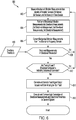
- stator inter-turn fault detection process 400 for detecting stator winding inter-turn faults or shorts that can occur with the electrical generator.
- the stator inter-turn fault detection process 400 can be represented as a series of steps and operations written in computer executable software code that can be implemented or run by the fault analyzer 302 of the detection system 300.
- the detection system 300 make mechanical vibration measurements using one or more of the vibration sensors 160 disposed on the generator housing 110 of the electrical generator 104.
- the mechanical vibration measurements represent physical, periodic displacements of the generator housing 110 and the vibration sensors 160 measure the mechanical vibrations in terms of acceleration (e.g. m/s 2 ) or changes in acceleration over time.
- the vibration sensors 160 can obtain time-dependent data 500 representing vibration measurements in terms of acceleration (Y-axis) with respect to or as a function of time (X-axis).
- the time data 500 can be depicted by three individual time charts, 502, 504, and 506, that can represent mechanical vibration measurements made by vibration sensors 160 at three separate locations on the generator housing 110 and/or can be associated with the three coordinates including the axial vibration measurements 162, vertical vibration measurements 164, and traverse vibration measurements 166.
- fewer or more vibration sensors and/or directions may be used.
- FIG. 5 depicts mechanical vibration measurements of a normally operating electrical generator 104, as indicated by the normal vibration curve 510, during which the rotor 120 concentrically and symmetrically rotates in the stator 122.
- FIG. 5 also depicts mechanical vibration measurements of an electrical generator 104 operating with a stator winding inter-turn fault as indicated by the fault vibration curve 512.
- Asymmetric or eccentric rotation of the rotor 120 caused by the stator winding inter-turn fault increases the displacement and the acceleration of the displacement that is measured by the vibration sensors 160, and thus the amplitude of the fault vibration curve 512 is larger than the amplitude or magnitude of the normal vibration curve 510. Because the vibrations associated with the electrical generator 104 will occur continuously as the generator operates, the normal vibration curve 510 and the fault vibration curve 512 can be represented as periodic sine waves or a periodic sinusoid curve in time.
- the stator inter-turn fault detection process 400 can include a conversion step 404 as illustrated in FIG. 4 .
- the conversion step 404 can utilize a Fourier transformation calculation or other time-frequency conversion techniques to convert the mechanical vibration measurements from time data 500, indicated by the individual time charts 502, 504, 506 in FIG. 5 , to frequency data 520 as indicated by frequency charts.
- the mechanical vibration measurements are represented according to their constituent frequencies and related variables, i.e. amplitude and/or phase.
- the frequency data 520 can depict the components of the mechanical vibration measurements according to their different frequencies (X-axis) measured in hertz and depicts their respective acceleration (Y-axis) as the amplitude or magnitude of the resulting curve.
- the fault analyzer 302 can be configured to be programmed or include circuitry to perform Fourier logic 320, for example, by conducting a fast Fourier transformation calculation. Thereafter, the detection system 300 can analyze the resulting frequency spectra in the frequency data 520 for indicia of a stator winding inter-turn fault.
- the stator inter-turn fault detection process 400 can conduct harmonic analysis to isolate various harmonics in the frequency data.
- the different frequencies depicted in the frequency data 520 can be associated with the different harmonics of the mechanical vibration measurements.
- the normal vibration curve 530 and the fault vibration curve 532 of the frequency data 520 can include a fundamental harmonic and one or more higher order harmonics, which may be multiples of the fundamental harmonic.
- the fundamental harmonic of the mechanical vibration measurements may occur at a specific frequency in hertz
- the second harmonic will occur at twice that frequency
- the third harmonic will occur at three times that frequency
- the fourth harmonic will occur at four times that frequency.
- the stator inter-turn fault detection process 400 can include an isolation step 406 in which a higher order harmonic in the frequency spectrum depicting the frequency data 520 is separated from the fundamental harmonic and other higher order harmonics.
- the isolated harmonic can occur at a specific frequency, indicated by rectangle 534, which is a multiple of the fundamental frequency. Because the mechanical vibration measurements associated with the stator winding inter-turn fault are larger than the mechanical vibration measurements associated with a normal operation, the acceleration (i.e. amplitude or magnitude) of the fault vibration curve 532 at the isolated higher order harmonic 534 can be larger than the acceleration (amplitude or magnitude) of the normal vibration curve 530.
- the isolated higher order harmonic 534 identified by the isolation step 406 can be the second order harmonic of the mechanical vibration measurements made by the vibration sensors 160.
- the isolation step 406 can use a band-pass filter that passes certain signals having certain frequencies while blocking others.
- the band-pass filter 322 can be embodied as an electronic circuit operatively associated with the microprocessor 304 of the detection system 300.
- the stator inter-turn fault detection process 400 can conduct a comparison step 408 in which the acceleration of the mechanical vibration measurements (i.e. amplitude or magnitude of the frequency charts) associated with the isolated higher order harmonic are compared with a predetermined threshold value 410 indicative of a stator winding inter-turn fault.
- the threshold value 410 can be predetermined empirically by operating the genset 100 or similar gensets normally or having varying degrees of stator winding inter-turn faults and the resulting mechanical vibration of the electrical generator measured. For example, the threshold value 410 can equate with the normal operation plot 530 in FIG. 5 and the comparison with the isolated higher order harmonic 534 can be made at that frequency.
- the microprocessor 304 can include a comparator 324 in the form of programming logic or circuitry to determine which of the two inputs (i.e. isolated higher order harmonic or threshold value) has a greater amplitude or magnitude.
- the stator inter-turn fault detection process 400 can conduct a fault signaling step 412.
- the detection system 300 may generate a fault signal indicative of the stator winding inter-turn fault that can be output through the HMI 312 as a visual or audible alarm.
- the fault analyzer 302 can also conduct a transmission step 414 to transmit the fault signal to the network 316 via the network transceiver 314.
- the detection system 300 can also be configured to detect winding inter-turn faults with the rotor 120.
- FIG. 6 there is illustrated a rotor inter-turn fault detection process 600 that can be implemented or run by the fault analyzer 302 of the detection system 300.
- the detection system 300 makes mechanical vibration measurements using the vibration sensors 160 disposed on the generator housing 110 of the electrical generator 104.
- the mechanical vibration measurements represent physical periodic displacements of the generator housing 110 and the vibration sensors 160 measure the mechanical vibrations in terms of acceleration (e.g. m/s 2 ) or changes in acceleration over time.
- the mechanical vibration measurements can be made from a plurality of vibration sensors 160 and can be resolved or partitioned into a plurality of directions.
- the rotor inter-turn fault detection process 600 can include a partitioning step 604.
- the vibration sensors 160 may be of the multi-axis configuration and can output electrical signals corresponding to the different directions of the mechanical vibration measurements over different identifiable data signaling channels.
- the data signaling channel can be multiplexed or remain distinct.
- the vibration sensors 160 may be single axis and output an electrical signal uniquely corresponding to a particular direction of the mechanical vibration measurements. Referring to FIG.
- the fault analyzer 302 can include a de-multiplexer or similar data selector logic 326 or circuitry.
- the mechanical vibration measurements can include at least a first directional measurement, a second directional measurement, and a third directional measurement.
- a chart 700 depicting a first sub-chart 702 of the first directional measurement, a second sub-chart 704 of the second directional measurement, and a third sub-chart 706 of the third directional measurement.
- the first, second, and third sub-charts 702, 704, and 704 can correspond to axial vibration measurements 162, vertical vibration measurements 164, and traverse vibration measurements 166 associated with the electrical generator 104.
- the chart 700 represents measurements from a plurality of different vibration sensors, indicated by bracket 708, at different locations on the generator housing 110.
- FIG. 7 depicts data corresponding to mechanical vibration measurements of a normally operating electrical generator 104 as indicated by the normal vibration curves 710.
- FIG. 7 also depicts data corresponding to mechanical vibration measurements of an electrical generator 104 operating with a rotor winding inter-turn fault as indicated by the fault vibration curve 712. Because the asymmetric or eccentric rotation of the rotor 120 caused by the rotor inter-turn fault increases the displacement measured by the vibration sensors 160, the acceleration (i.e. amplitude) of the fault vibration curve 712 is larger than the acceleration (i.e. amplitude) of the normal vibration curve 710.
- the data depicted in the chart 700 and sub-charts 702, 704, 706 can be frequency-dependent data in the frequency domain with the acceleration (Y-axis) measured with respect to frequency measured in hertz (X-axis).
- the frequency domain data represented in chart 700 can be initially obtained as time-dependent data and converted to the frequency domain for ease of analysis.
- the rotor inter-turn fault detection process 600 can include a conversion step 606 to convert from the time domain to the frequency domain, for example, by a fast Fourier transformation. Conversion between time data and frequency data can be accomplished by the Fourier logic 320 of the fault analyzer 302.
- the rotor inter-turn fault detection process 600 can proceed to a comparison step 608 in which the magnitude of the mechanical vibration measurements associated with the higher order harmonic are compared with threshold values 610 indicative of a rotor winding inter-turn fault.
- the threshold values 610 can include a first threshold value to compare with the first directional measurement, a second threshold value to compare with the second directional measurement, and a third threshold value to compare with the third directional measurement.
- the directional measurements and the threshold values can be compared on the basis of acceleration (i.e. amplitude or magnitude) correlating with the mechanical vibration measurements.
- the first, second, and third threshold values may be the same or different from each other.
- the threshold values 610 can be predetermined empirically as described above. If the directional measurements do not exceed the threshold values 610, the rotor inter-turn fault detection process 600 can return to the measurement step 602.
- the rotor inter-turn fault detection process 600 can assess whether the electrical generator is vibrating or fluctuating in multiple directions, for example, at least the three Cartesian directions. Measureable vibrations in a particular number of directions may be indicative of an unbalanced electrical generator 104. A query step 612 can make this determination based on the number or analysis of the sub-charts 702, 704, 706 associated with the different directions. If mechanical vibration measurements do not occur in a particular number of directions, such as a minimum number of directions, the rotor inter-turn fault detection process 600 can return to the measurement step 602.
- the rotor inter-turn fault process 600 can conduct another fault signaling step 614.
- the detection system 300 can generate a fault signal indicative of a rotor winding inter-turn fault output through the HMI 312.
- the rotor inter-turn fault process 600 can also include a transmission step 616 to transmit the fault signal to the network 316 via the network transceiver 314.
- the detection system 300 for detecting winding inter-turn faults with stator and/or rotor windings can be provided as an embedded system incorporated with gensets 100 as they are assembled.
- the threshold values for comparison with the mechanical vibration measurements can be obtained during assembly of the genset 100.
- the detection system 300 can also be provided as an aftermarket kit for fitting to gensets 100 operating in the field.
- the plurality of vibration sensors 160 and the fault analyzer 302 can be provided together as a kit or package.
- the vibration sensors 160 can be mounted to the exterior of the generator housing 110 at select locations without accessing the interior of the electrical generator 104 or interfering with the arrangement and clearances of the moving internal components of the generator.
- the fault analyzer 302 can be accommodated into the control panel 114 or, in an embodiment, may be uploaded to existing computing devices in the control panel.
- the information obtained by detection system 300 can be transmitted to a remote backend system 318 for further analysis and storage.
- the mechanical vibration measurements and the associated analysis conducted by the detection system 300 can be transmitted to the backend system 318 over the network 316 via the transceiver 314.
- the backend system 318 may provide updated threshold value for comparison with the mechanical vibration measurements, may track a progress log of the mechanical vibration measurements, and may arrange for corrective action to be taken to remedy identified inter-turn fault and similar winding faults occurring with the stator and/or rotor windings.
Landscapes
- Physics & Mathematics (AREA)
- General Physics & Mathematics (AREA)
- Engineering & Computer Science (AREA)
- Power Engineering (AREA)
- Testing Of Short-Circuits, Discontinuities, Leakage, Or Incorrect Line Connections (AREA)
Applications Claiming Priority (1)
| Application Number | Priority Date | Filing Date | Title |
|---|---|---|---|
| US16/837,701 US11619670B2 (en) | 2020-04-01 | 2020-04-01 | System and method for detecting winding faults in a generator |
Publications (2)
| Publication Number | Publication Date |
|---|---|
| EP3889559A2 true EP3889559A2 (de) | 2021-10-06 |
| EP3889559A3 EP3889559A3 (de) | 2021-12-15 |
Family
ID=74867407
Family Applications (1)
| Application Number | Title | Priority Date | Filing Date |
|---|---|---|---|
| EP21161391.4A Withdrawn EP3889559A3 (de) | 2020-04-01 | 2021-03-08 | System und verfahren zur erkennung von wicklungsfehlern in einem generator |
Country Status (5)
| Country | Link |
|---|---|
| US (1) | US11619670B2 (de) |
| EP (1) | EP3889559A3 (de) |
| CN (1) | CN113495229A (de) |
| AU (1) | AU2021201558A1 (de) |
| CA (1) | CA3113264A1 (de) |
Families Citing this family (6)
| Publication number | Priority date | Publication date | Assignee | Title |
|---|---|---|---|---|
| AT524650B1 (de) * | 2021-03-04 | 2022-08-15 | Seibt Kristl & Co Gmbh | Verfahren und Vorrichtung zur Überwachung der Position einer Welle |
| JP2022166404A (ja) * | 2021-04-21 | 2022-11-02 | 日本電気株式会社 | 異常検出装置、異常検出方法、及びプログラム |
| US11506717B1 (en) * | 2021-10-11 | 2022-11-22 | King Fahd University Of Petroleum And Minerals | System and method for diagnosing stator inter-turn faults in synchronous motors |
| US12418223B2 (en) | 2021-12-16 | 2025-09-16 | Caterpillar Inc. | System, apparatus, and method for monitoring a generator |
| CN115015756A (zh) * | 2022-07-14 | 2022-09-06 | 深圳市文浩科技有限公司 | 一种细碎融合的新材料混合机故障诊断方法 |
| CN117969449B (zh) * | 2024-03-29 | 2024-07-05 | 三峡金沙江云川水电开发有限公司 | 一种太赫兹检测发电机定子线棒绝缘缺陷的方法及系统 |
Citations (1)
| Publication number | Priority date | Publication date | Assignee | Title |
|---|---|---|---|---|
| EP3220120A1 (de) * | 2016-03-17 | 2017-09-20 | ABB Schweiz AG | Verfahren, diagnostische vorrichtung und system zur bestimmung von fehlerzuständen in einer elektrischen maschine |
Family Cites Families (16)
| Publication number | Priority date | Publication date | Assignee | Title |
|---|---|---|---|---|
| US6144924A (en) * | 1996-05-20 | 2000-11-07 | Crane Nuclear, Inc. | Motor condition and performance analyzer |
| EP1113253A4 (de) | 1999-06-21 | 2006-11-02 | Furukawa Electric Co Ltd | Drehsensor und dazugehörige messschaltung |
| EP1451550B1 (de) * | 2001-12-04 | 2007-07-11 | Skf Condition Monitoring, Inc. | System und verfahren zur identifikation des vorhandenseins von defekten in einer vibrierenden maschine |
| US7834573B2 (en) * | 2007-07-31 | 2010-11-16 | Caterpillar Inc | Winding fault detection system |
| CN101710162A (zh) | 2009-11-27 | 2010-05-19 | 华北电力大学(保定) | 基于定子铁心振动的电机转子绕组匝间短路故障诊断方法 |
| EP2421146B1 (de) | 2010-08-16 | 2015-02-11 | Baumüller Nürnberg GmbH | Vorrichtung und Verfahren zur drehgeberlosen Identifikation magnetomechanischer Kenngrößen eines Drehstrom-Synchronmotors |
| EP2518456A1 (de) * | 2011-04-29 | 2012-10-31 | ABB Technology AG | Verfahren zur Entmagnetisierungsüberwachung |
| KR101326586B1 (ko) | 2012-01-18 | 2013-11-07 | 고려대학교 산학협력단 | 유도 전동기의 회전자 결함 진단 장치, 방법 및 상기 방법을 실행시키기 위한 컴퓨터 판독 가능한 프로그램을 기록한 매체 |
| US8731743B2 (en) * | 2012-04-11 | 2014-05-20 | Textron Innovations Inc. | Self tuning vibration isolation system |
| US9234931B2 (en) * | 2013-03-08 | 2016-01-12 | Caterpillar Inc. | Fault detection system with leakage current detection |
| CN103823150B (zh) | 2013-12-11 | 2017-01-11 | 贵州电力试验研究院 | 多传感器联合的汽轮发电机转子匝间短路故障诊断方法 |
| CN105548799B (zh) | 2015-12-06 | 2019-01-11 | 国家电网公司 | 发电电动机转子绕组匝间短路故障的在线监测方法 |
| US10408879B2 (en) * | 2016-10-10 | 2019-09-10 | Rolls-Royce Plc | Method and apparatus for diagnosing a fault condition in an electric machine |
| CN106525337B (zh) | 2016-11-30 | 2019-03-29 | 北京中元瑞讯科技有限公司 | 基于在线数据的水轮发电机组磁拉力不平衡故障分析方法 |
| US10695907B2 (en) * | 2017-09-29 | 2020-06-30 | Intel Corporation | Methods and apparatus for monitoring robot health in manufacturing environments |
| DE102020133906A1 (de) * | 2020-12-17 | 2022-06-23 | Dana Belgium N.V. | Elektrische Antriebseinheit |
-
2020
- 2020-04-01 US US16/837,701 patent/US11619670B2/en active Active
-
2021
- 2021-03-08 EP EP21161391.4A patent/EP3889559A3/de not_active Withdrawn
- 2021-03-11 AU AU2021201558A patent/AU2021201558A1/en active Pending
- 2021-03-25 CN CN202110320239.7A patent/CN113495229A/zh active Pending
- 2021-03-25 CA CA3113264A patent/CA3113264A1/en active Pending
Patent Citations (1)
| Publication number | Priority date | Publication date | Assignee | Title |
|---|---|---|---|---|
| EP3220120A1 (de) * | 2016-03-17 | 2017-09-20 | ABB Schweiz AG | Verfahren, diagnostische vorrichtung und system zur bestimmung von fehlerzuständen in einer elektrischen maschine |
Also Published As
| Publication number | Publication date |
|---|---|
| US11619670B2 (en) | 2023-04-04 |
| EP3889559A3 (de) | 2021-12-15 |
| US20210311122A1 (en) | 2021-10-07 |
| CA3113264A1 (en) | 2021-10-01 |
| AU2021201558A1 (en) | 2021-10-21 |
| CN113495229A (zh) | 2021-10-12 |
Similar Documents
| Publication | Publication Date | Title |
|---|---|---|
| US11619670B2 (en) | System and method for detecting winding faults in a generator | |
| Mirzaeva et al. | Advanced diagnosis of stator turn-to-turn faults and static eccentricity in induction motors based on internal flux measurement | |
| Panagiotou et al. | A new approach for broken rotor bar detection in induction motors using frequency extraction in stray flux signals | |
| Park et al. | Stray flux monitoring for reliable detection of rotor faults under the influence of rotor axial air ducts | |
| Faiz et al. | Finite-element transient analysis of induction motors under mixed eccentricity fault | |
| Irhoumah et al. | Detection of the stator winding inter-turn faults in asynchronous and synchronous machines through the correlation between harmonics of the voltage of two magnetic flux sensors | |
| Ehya et al. | Pattern recognition of interturn short circuit fault in a synchronous generator using magnetic flux | |
| Li et al. | Performance analysis of a three-phase induction machine with inclined static eccentricity | |
| Da et al. | A new approach to fault diagnostics for permanent magnet synchronous machines using electromagnetic signature analysis | |
| Siddique et al. | A review of stator fault monitoring techniques of induction motors | |
| Kim et al. | Power spectrum-based detection of induction motor rotor faults for immunity to false alarms | |
| Concari et al. | Differential diagnosis based on multivariable monitoring to assess induction machine rotor conditions | |
| Cuevas et al. | Noninvasive detection of winding short-circuit faults in salient pole synchronous machine with squirrel-cage damper | |
| EP3090269A1 (de) | System zur zustandsüberwachung einer elektrischen maschine, mobiltelefon und verfahren dafür | |
| Yousefi kia et al. | Hybrid modelling of doubly fed induction generators with inter‐turn stator fault and its detection method using wavelet analysis | |
| US20110215750A1 (en) | Vibration Monitoring of a Magnetic Element in an Electrical Machine | |
| Barański | New vibration diagnostic method of PM generators and traction motors-detecting of vibrations caused by unbalance | |
| Drubel et al. | End winding deformations in different turbo generators during 3-phase short circuit and full load operation | |
| Bissonnette | End-winding vibration monitoring and interpretation | |
| Jiang et al. | Electromagnetic Force and Mechanical Response of Turbo‐Generator End Winding under Electromechanical Faults | |
| Widagdo et al. | Detection of Air Gap Eccentricity on Three-Phase Induction Motor Using 3-Axis Digital ELF Gaussmeter | |
| Chai et al. | Misalignment detection of rotor system based on adaptive input-output model identification of motor speed | |
| WO2024047190A1 (en) | Fault detection in synchronous machines using pattern recognition | |
| Penman et al. | A new approach to the protection of industrial drives | |
| Zhou et al. | Eccentricity diagnosis of electric machines using harmonic ratio-based indices from resolvers |
Legal Events
| Date | Code | Title | Description |
|---|---|---|---|
| PUAI | Public reference made under article 153(3) epc to a published international application that has entered the european phase |
Free format text: ORIGINAL CODE: 0009012 |
|
| STAA | Information on the status of an ep patent application or granted ep patent |
Free format text: STATUS: THE APPLICATION HAS BEEN PUBLISHED |
|
| AK | Designated contracting states |
Kind code of ref document: A2 Designated state(s): AL AT BE BG CH CY CZ DE DK EE ES FI FR GB GR HR HU IE IS IT LI LT LU LV MC MK MT NL NO PL PT RO RS SE SI SK SM TR |
|
| PUAL | Search report despatched |
Free format text: ORIGINAL CODE: 0009013 |
|
| AK | Designated contracting states |
Kind code of ref document: A3 Designated state(s): AL AT BE BG CH CY CZ DE DK EE ES FI FR GB GR HR HU IE IS IT LI LT LU LV MC MK MT NL NO PL PT RO RS SE SI SK SM TR |
|
| RIC1 | Information provided on ipc code assigned before grant |
Ipc: H02K 15/00 20060101ALI20211108BHEP Ipc: G01R 31/34 20200101ALI20211108BHEP Ipc: G01H 13/00 20060101ALI20211108BHEP Ipc: G01H 1/00 20060101AFI20211108BHEP |
|
| STAA | Information on the status of an ep patent application or granted ep patent |
Free format text: STATUS: REQUEST FOR EXAMINATION WAS MADE |
|
| 17P | Request for examination filed |
Effective date: 20220613 |
|
| RBV | Designated contracting states (corrected) |
Designated state(s): AL AT BE BG CH CY CZ DE DK EE ES FI FR GB GR HR HU IE IS IT LI LT LU LV MC MK MT NL NO PL PT RO RS SE SI SK SM TR |
|
| STAA | Information on the status of an ep patent application or granted ep patent |
Free format text: STATUS: EXAMINATION IS IN PROGRESS |
|
| 17Q | First examination report despatched |
Effective date: 20230619 |
|
| STAA | Information on the status of an ep patent application or granted ep patent |
Free format text: STATUS: THE APPLICATION HAS BEEN WITHDRAWN |
|
| 18W | Application withdrawn |
Effective date: 20241010 |