EP3889521A1 - Control device and air conditioning device - Google Patents
Control device and air conditioning device Download PDFInfo
- Publication number
- EP3889521A1 EP3889521A1 EP18867314.9A EP18867314A EP3889521A1 EP 3889521 A1 EP3889521 A1 EP 3889521A1 EP 18867314 A EP18867314 A EP 18867314A EP 3889521 A1 EP3889521 A1 EP 3889521A1
- Authority
- EP
- European Patent Office
- Prior art keywords
- supercooling
- refrigerant
- outdoor unit
- temperature
- circuit
- Prior art date
- Legal status (The legal status is an assumption and is not a legal conclusion. Google has not performed a legal analysis and makes no representation as to the accuracy of the status listed.)
- Granted
Links
Images



Classifications
-
- F—MECHANICAL ENGINEERING; LIGHTING; HEATING; WEAPONS; BLASTING
- F25—REFRIGERATION OR COOLING; COMBINED HEATING AND REFRIGERATION SYSTEMS; HEAT PUMP SYSTEMS; MANUFACTURE OR STORAGE OF ICE; LIQUEFACTION SOLIDIFICATION OF GASES
- F25B—REFRIGERATION MACHINES, PLANTS OR SYSTEMS; COMBINED HEATING AND REFRIGERATION SYSTEMS; HEAT PUMP SYSTEMS
- F25B13/00—Compression machines, plants or systems, with reversible cycle
-
- F—MECHANICAL ENGINEERING; LIGHTING; HEATING; WEAPONS; BLASTING
- F25—REFRIGERATION OR COOLING; COMBINED HEATING AND REFRIGERATION SYSTEMS; HEAT PUMP SYSTEMS; MANUFACTURE OR STORAGE OF ICE; LIQUEFACTION SOLIDIFICATION OF GASES
- F25B—REFRIGERATION MACHINES, PLANTS OR SYSTEMS; COMBINED HEATING AND REFRIGERATION SYSTEMS; HEAT PUMP SYSTEMS
- F25B1/00—Compression machines, plants or systems with non-reversible cycle
-
- F—MECHANICAL ENGINEERING; LIGHTING; HEATING; WEAPONS; BLASTING
- F25—REFRIGERATION OR COOLING; COMBINED HEATING AND REFRIGERATION SYSTEMS; HEAT PUMP SYSTEMS; MANUFACTURE OR STORAGE OF ICE; LIQUEFACTION SOLIDIFICATION OF GASES
- F25B—REFRIGERATION MACHINES, PLANTS OR SYSTEMS; COMBINED HEATING AND REFRIGERATION SYSTEMS; HEAT PUMP SYSTEMS
- F25B49/00—Arrangement or mounting of control or safety devices
- F25B49/02—Arrangement or mounting of control or safety devices for compression type machines, plants or systems
-
- F—MECHANICAL ENGINEERING; LIGHTING; HEATING; WEAPONS; BLASTING
- F25—REFRIGERATION OR COOLING; COMBINED HEATING AND REFRIGERATION SYSTEMS; HEAT PUMP SYSTEMS; MANUFACTURE OR STORAGE OF ICE; LIQUEFACTION SOLIDIFICATION OF GASES
- F25B—REFRIGERATION MACHINES, PLANTS OR SYSTEMS; COMBINED HEATING AND REFRIGERATION SYSTEMS; HEAT PUMP SYSTEMS
- F25B2313/00—Compression machines, plants or systems with reversible cycle not otherwise provided for
- F25B2313/005—Outdoor unit expansion valves
-
- F—MECHANICAL ENGINEERING; LIGHTING; HEATING; WEAPONS; BLASTING
- F25—REFRIGERATION OR COOLING; COMBINED HEATING AND REFRIGERATION SYSTEMS; HEAT PUMP SYSTEMS; MANUFACTURE OR STORAGE OF ICE; LIQUEFACTION SOLIDIFICATION OF GASES
- F25B—REFRIGERATION MACHINES, PLANTS OR SYSTEMS; COMBINED HEATING AND REFRIGERATION SYSTEMS; HEAT PUMP SYSTEMS
- F25B2313/00—Compression machines, plants or systems with reversible cycle not otherwise provided for
- F25B2313/023—Compression machines, plants or systems with reversible cycle not otherwise provided for using multiple indoor units
- F25B2313/0233—Compression machines, plants or systems with reversible cycle not otherwise provided for using multiple indoor units in parallel arrangements
-
- F—MECHANICAL ENGINEERING; LIGHTING; HEATING; WEAPONS; BLASTING
- F25—REFRIGERATION OR COOLING; COMBINED HEATING AND REFRIGERATION SYSTEMS; HEAT PUMP SYSTEMS; MANUFACTURE OR STORAGE OF ICE; LIQUEFACTION SOLIDIFICATION OF GASES
- F25B—REFRIGERATION MACHINES, PLANTS OR SYSTEMS; COMBINED HEATING AND REFRIGERATION SYSTEMS; HEAT PUMP SYSTEMS
- F25B2313/00—Compression machines, plants or systems with reversible cycle not otherwise provided for
- F25B2313/025—Compression machines, plants or systems with reversible cycle not otherwise provided for using multiple outdoor units
- F25B2313/0253—Compression machines, plants or systems with reversible cycle not otherwise provided for using multiple outdoor units in parallel arrangements
-
- F—MECHANICAL ENGINEERING; LIGHTING; HEATING; WEAPONS; BLASTING
- F25—REFRIGERATION OR COOLING; COMBINED HEATING AND REFRIGERATION SYSTEMS; HEAT PUMP SYSTEMS; MANUFACTURE OR STORAGE OF ICE; LIQUEFACTION SOLIDIFICATION OF GASES
- F25B—REFRIGERATION MACHINES, PLANTS OR SYSTEMS; COMBINED HEATING AND REFRIGERATION SYSTEMS; HEAT PUMP SYSTEMS
- F25B2313/00—Compression machines, plants or systems with reversible cycle not otherwise provided for
- F25B2313/027—Compression machines, plants or systems with reversible cycle not otherwise provided for characterised by the reversing means
- F25B2313/02742—Compression machines, plants or systems with reversible cycle not otherwise provided for characterised by the reversing means using two four-way valves
-
- F—MECHANICAL ENGINEERING; LIGHTING; HEATING; WEAPONS; BLASTING
- F25—REFRIGERATION OR COOLING; COMBINED HEATING AND REFRIGERATION SYSTEMS; HEAT PUMP SYSTEMS; MANUFACTURE OR STORAGE OF ICE; LIQUEFACTION SOLIDIFICATION OF GASES
- F25B—REFRIGERATION MACHINES, PLANTS OR SYSTEMS; COMBINED HEATING AND REFRIGERATION SYSTEMS; HEAT PUMP SYSTEMS
- F25B2313/00—Compression machines, plants or systems with reversible cycle not otherwise provided for
- F25B2313/031—Sensor arrangements
- F25B2313/0315—Temperature sensors near the outdoor heat exchanger
-
- F—MECHANICAL ENGINEERING; LIGHTING; HEATING; WEAPONS; BLASTING
- F25—REFRIGERATION OR COOLING; COMBINED HEATING AND REFRIGERATION SYSTEMS; HEAT PUMP SYSTEMS; MANUFACTURE OR STORAGE OF ICE; LIQUEFACTION SOLIDIFICATION OF GASES
- F25B—REFRIGERATION MACHINES, PLANTS OR SYSTEMS; COMBINED HEATING AND REFRIGERATION SYSTEMS; HEAT PUMP SYSTEMS
- F25B2345/00—Details for charging or discharging refrigerants; Service stations therefor
- F25B2345/001—Charging refrigerant to a cycle
-
- F—MECHANICAL ENGINEERING; LIGHTING; HEATING; WEAPONS; BLASTING
- F25—REFRIGERATION OR COOLING; COMBINED HEATING AND REFRIGERATION SYSTEMS; HEAT PUMP SYSTEMS; MANUFACTURE OR STORAGE OF ICE; LIQUEFACTION SOLIDIFICATION OF GASES
- F25B—REFRIGERATION MACHINES, PLANTS OR SYSTEMS; COMBINED HEATING AND REFRIGERATION SYSTEMS; HEAT PUMP SYSTEMS
- F25B2400/00—Component parts or details not otherwise provided for in this subclass
- F25B2400/07—Details of compressors or related parts
- F25B2400/075—Details of compressors or related parts with parallel compressors
-
- F—MECHANICAL ENGINEERING; LIGHTING; HEATING; WEAPONS; BLASTING
- F25—REFRIGERATION OR COOLING; COMBINED HEATING AND REFRIGERATION SYSTEMS; HEAT PUMP SYSTEMS; MANUFACTURE OR STORAGE OF ICE; LIQUEFACTION SOLIDIFICATION OF GASES
- F25B—REFRIGERATION MACHINES, PLANTS OR SYSTEMS; COMBINED HEATING AND REFRIGERATION SYSTEMS; HEAT PUMP SYSTEMS
- F25B2500/00—Problems to be solved
- F25B2500/24—Low amount of refrigerant in the system
-
- F—MECHANICAL ENGINEERING; LIGHTING; HEATING; WEAPONS; BLASTING
- F25—REFRIGERATION OR COOLING; COMBINED HEATING AND REFRIGERATION SYSTEMS; HEAT PUMP SYSTEMS; MANUFACTURE OR STORAGE OF ICE; LIQUEFACTION SOLIDIFICATION OF GASES
- F25B—REFRIGERATION MACHINES, PLANTS OR SYSTEMS; COMBINED HEATING AND REFRIGERATION SYSTEMS; HEAT PUMP SYSTEMS
- F25B2600/00—Control issues
- F25B2600/02—Compressor control
- F25B2600/025—Compressor control by controlling speed
- F25B2600/0253—Compressor control by controlling speed with variable speed
-
- F—MECHANICAL ENGINEERING; LIGHTING; HEATING; WEAPONS; BLASTING
- F25—REFRIGERATION OR COOLING; COMBINED HEATING AND REFRIGERATION SYSTEMS; HEAT PUMP SYSTEMS; MANUFACTURE OR STORAGE OF ICE; LIQUEFACTION SOLIDIFICATION OF GASES
- F25B—REFRIGERATION MACHINES, PLANTS OR SYSTEMS; COMBINED HEATING AND REFRIGERATION SYSTEMS; HEAT PUMP SYSTEMS
- F25B2600/00—Control issues
- F25B2600/11—Fan speed control
-
- F—MECHANICAL ENGINEERING; LIGHTING; HEATING; WEAPONS; BLASTING
- F25—REFRIGERATION OR COOLING; COMBINED HEATING AND REFRIGERATION SYSTEMS; HEAT PUMP SYSTEMS; MANUFACTURE OR STORAGE OF ICE; LIQUEFACTION SOLIDIFICATION OF GASES
- F25B—REFRIGERATION MACHINES, PLANTS OR SYSTEMS; COMBINED HEATING AND REFRIGERATION SYSTEMS; HEAT PUMP SYSTEMS
- F25B2600/00—Control issues
- F25B2600/19—Refrigerant outlet condenser temperature
-
- F—MECHANICAL ENGINEERING; LIGHTING; HEATING; WEAPONS; BLASTING
- F25—REFRIGERATION OR COOLING; COMBINED HEATING AND REFRIGERATION SYSTEMS; HEAT PUMP SYSTEMS; MANUFACTURE OR STORAGE OF ICE; LIQUEFACTION SOLIDIFICATION OF GASES
- F25B—REFRIGERATION MACHINES, PLANTS OR SYSTEMS; COMBINED HEATING AND REFRIGERATION SYSTEMS; HEAT PUMP SYSTEMS
- F25B2600/00—Control issues
- F25B2600/25—Control of valves
- F25B2600/2509—Economiser valves
-
- F—MECHANICAL ENGINEERING; LIGHTING; HEATING; WEAPONS; BLASTING
- F25—REFRIGERATION OR COOLING; COMBINED HEATING AND REFRIGERATION SYSTEMS; HEAT PUMP SYSTEMS; MANUFACTURE OR STORAGE OF ICE; LIQUEFACTION SOLIDIFICATION OF GASES
- F25B—REFRIGERATION MACHINES, PLANTS OR SYSTEMS; COMBINED HEATING AND REFRIGERATION SYSTEMS; HEAT PUMP SYSTEMS
- F25B2600/00—Control issues
- F25B2600/25—Control of valves
- F25B2600/2513—Expansion valves
-
- F—MECHANICAL ENGINEERING; LIGHTING; HEATING; WEAPONS; BLASTING
- F25—REFRIGERATION OR COOLING; COMBINED HEATING AND REFRIGERATION SYSTEMS; HEAT PUMP SYSTEMS; MANUFACTURE OR STORAGE OF ICE; LIQUEFACTION SOLIDIFICATION OF GASES
- F25B—REFRIGERATION MACHINES, PLANTS OR SYSTEMS; COMBINED HEATING AND REFRIGERATION SYSTEMS; HEAT PUMP SYSTEMS
- F25B2700/00—Sensing or detecting of parameters; Sensors therefor
- F25B2700/19—Pressures
- F25B2700/193—Pressures of the compressor
- F25B2700/1931—Discharge pressures
-
- F—MECHANICAL ENGINEERING; LIGHTING; HEATING; WEAPONS; BLASTING
- F25—REFRIGERATION OR COOLING; COMBINED HEATING AND REFRIGERATION SYSTEMS; HEAT PUMP SYSTEMS; MANUFACTURE OR STORAGE OF ICE; LIQUEFACTION SOLIDIFICATION OF GASES
- F25B—REFRIGERATION MACHINES, PLANTS OR SYSTEMS; COMBINED HEATING AND REFRIGERATION SYSTEMS; HEAT PUMP SYSTEMS
- F25B2700/00—Sensing or detecting of parameters; Sensors therefor
- F25B2700/21—Temperatures
- F25B2700/2116—Temperatures of a condenser
- F25B2700/21163—Temperatures of a condenser of the refrigerant at the outlet of the condenser
-
- Y—GENERAL TAGGING OF NEW TECHNOLOGICAL DEVELOPMENTS; GENERAL TAGGING OF CROSS-SECTIONAL TECHNOLOGIES SPANNING OVER SEVERAL SECTIONS OF THE IPC; TECHNICAL SUBJECTS COVERED BY FORMER USPC CROSS-REFERENCE ART COLLECTIONS [XRACs] AND DIGESTS
- Y02—TECHNOLOGIES OR APPLICATIONS FOR MITIGATION OR ADAPTATION AGAINST CLIMATE CHANGE
- Y02B—CLIMATE CHANGE MITIGATION TECHNOLOGIES RELATED TO BUILDINGS, e.g. HOUSING, HOUSE APPLIANCES OR RELATED END-USER APPLICATIONS
- Y02B30/00—Energy efficient heating, ventilation or air conditioning [HVAC]
- Y02B30/70—Efficient control or regulation technologies, e.g. for control of refrigerant flow, motor or heating
Definitions
- the present invention relates to a control device and an air-conditioning device.
- imbalance in a refrigerant amount in condensers of the outdoor units is caused upon determination on the refrigerant amount in refrigerant charging operation, and in some cases, a proper refrigerant amount for a refrigeration cycle cannot be determined.
- Patent Document 1 describes, as refrigerant amount balance control among the outdoor units, an example where the degree of supercooling at a condenser outlet of an outdoor unit is determined and a compressor rotation speed on a lower supercooling degree side is decreased as compared to a compressor rotation speed on a higher supercooling degree side and an example where a fan rotation speed on the lower supercooling degree side is increased as compared to a fan rotation speed on the higher supercooling degree side.
- Patent Document 1 a refrigerant amount in refrigerant charging operation is determined using the degree of supercooling at the condenser outlet of the outdoor unit, assuming that the degree of supercooling can be properly obtained at the condenser outlet of each outdoor unit.
- refrigerant at the condenser outlet of the outdoor unit is in a two-phase state, no temperature change is shown.
- refrigerant specific enthalpy change such a refrigerant specific enthalpy change cannot be determined, and the degree of supercooling at the condenser outlet of the outdoor unit cannot be properly obtained.
- the refrigerant amount in the refrigerant charging operation cannot be properly determined.
- the present invention is intended to properly determine the amount of refrigerant charged to a refrigerant circuit.
- the present invention relates to a control device of an air-conditioning device including multiple outdoor units and an indoor unit connected to the multiple outdoor units through a pipe.
- the control device includes a control section configured to obtain, before refrigerant charging to a refrigerant circuit including the multiple outdoor units and the indoor unit is completed, the degree of supercooling at an outlet of a supercooling circuit of each outdoor unit based on a temperature detected by a temperature sensor configured to detect the temperature of refrigerant having passed through the supercooling circuit of each outdoor unit, obtain a target value of the degree of supercooling based on the obtained multiple degrees of supercooling, and perform the control of increasing the rotation speed of a compressor of an outdoor unit having a higher degree of supercooling than the target value and decreasing the rotation speed of a compressor of an outdoor unit having a lower degree of supercooling than the target value such that a difference in the degree of supercooling at the outlet of the supercooling circuit of each outdoor unit is decreased.
- the amount of refrigerant charged to the refrigerant circuit can be properly determined.
- Fig. 1 is a diagram of one example of an outline configuration of an air-conditioning device of the first embodiment.
- the air-conditioning device is configured such that outdoor units 10a, 10b and indoor units 40a, 40b, 40c, 40d are connected to each other through a liquid pipe 31 and a gas pipe 30 to form a closed circuit.
- the closed circuit is sealed with refrigerant, and the refrigerant circulates to implement a refrigeration cycle.
- the number of connected outdoor units 10 described herein may be two or more as long as multiple units are provided.
- the number of connected indoor units 40 may be one.
- the outdoor unit 10a is one example of a control device of the air-conditioning device.
- the outdoor unit 10a is configured such that a compressor 11a whose rotation frequency is variable by an inverter, a four-way valve (a reversible valve) 12a, an outdoor heat exchanger 13a configured to exchange heat with outdoor air, an outdoor expansion valve 14a including an electronic expansion valve etc. for adjusting the flow rate of refrigerant in the outdoor heat exchanger 13a, a supercooling circuit 20a, a gas blocking valve 16a, a liquid blocking valve 17a, etc. are connected to each other through a pipe. Moreover, a supercooling bypass pipe 22a as a cooling source of the supercooling circuit 20a is provided at the outdoor unit 10a.
- the supercooling bypass pipe 22a is provided such that part of refrigerant sent from the outdoor expansion valve 14a to the liquid pipe 31 returns to the compressor 11a. More specifically, the supercooling bypass pipe 22a extends from between the outdoor expansion valve 14a and the supercooling circuit 20a, and is connected to a suction port side of the compressor 11a through the supercooling circuit 20a. Further, a supercooling expansion valve 23a configured to adjust the flow rate of refrigerant flowing in the supercooling bypass pipe 22a is provided at the supercooling bypass pipe 22a.
- a supercooling circuit outlet temperature sensor 60a is provided at the pipe in the vicinity of an outlet of the supercooling circuit 20a.
- the supercooling circuit outlet temperature sensor 60a detects the temperature of refrigerant at the pipe in the vicinity of the outlet of the supercooling circuit 20a.
- a refrigerant charging port 81a as a refrigerant charging opening is provided at the supercooling bypass pipe 22a, and a refrigerant charging electromagnetic valve 80a for refrigerant charging is provided downstream of the refrigerant charging port 81a.
- a refrigerant tank sealed with refrigerant is connected to the refrigerant charging port 81a through a charging hose.
- a high-pressure sensor 62a configured to detect the pressure of gas refrigerant discharged from the compressor 11a is provided at the discharge-side pipe of the compressor 11a.
- a control section 70a configured to control operation of the outdoor unit 10a is provided at the outdoor unit 10a.
- the control section 70a is connected to an outdoor fan 15a, the high-pressure sensor 62a, the outdoor expansion valve 14a, the supercooling expansion valve 23a, the supercooling circuit outlet temperature sensor 60a, the compressor 11a, the refrigerant charging electromagnetic valve 80a, and a control section 70b of the outdoor unit 10b so that a signal can be transmitted or received through a signal line.
- a configuration of the outdoor unit 10b is also similar to the configuration of the outdoor unit 10a.
- the control section 70a also transmits a signal to the control section 70b and also control the outdoor unit 10b via the control section 70b.
- the indoor unit 40a is configured such that an indoor heat exchanger 41a configured to exchange heat with indoor air and an indoor expansion valve 42a including an electronic expansion valve etc. for adjusting the flow rate of refrigerant in the indoor heat exchanger 41a are connected to each other through a pipe.
- Configurations of the indoor unit 40b, the indoor unit 40c, and the indoor unit 40d are similar to the configuration of the indoor unit 40a.
- Fig. 2 is a diagram of one example of a hardware configuration of the control section 70a.
- the control section 70a includes a CPU 201, a storage section 202, an input section 203, a display section 204, and a communication section 205.
- the CPU 201 reads a program stored in the storage section 202 to execute processing.
- the storage section 202 is used as a primary storage area, such as a main memory or a working area, upon execution of the processing by the CPU 201, and stores data (e.g., each threshold described later), programs, etc. used upon execution of the processing by the CPU 201.
- the storage section 202 is one example of a storage medium.
- the input section 203 is, for example, a button, and receives operation by a user to input such operation to the CPU 201.
- the display section 204 is, for example, a display, and displays a result of the processing by the CPU 201.
- the communication section 205 communicates with the outdoor unit 10b etc. via the signal line.
- the functions and processing of the control section 70a are implemented in such a manner that the CPU 201 executes the processing based on the programs stored in the storage section 202. Part of the functions and processing of the control section 70a may be, as another example, implemented using a hardware circuit.
- a hardware configuration of the control section 70b is also similar to the hardware configuration of the control section 70a.
- the control section 70a performs the processing of balancing a refrigerant amount between the outdoor units 10a, 10b upon refrigerant charging for the air-conditioning device.
- refrigerant charging it is necessary to determine whether or not the amount of refrigerant charged to the air-conditioning device is proper.
- the refrigerant amount needs to be balanced between the outdoor units 10a, 10b.
- the balance in the refrigerant amount between the outdoor units is not achieved due to an external factor etc.
- the air-conditioning device of the present embodiment adjusts the balance in the refrigerant amount by the control of the control section 70a, and in a state in which a proper balance in the refrigerant amount is achieved, determines whether or not the refrigerant amount is proper.
- Refrigerant charging will be described in advance of the processing of the control section 70a.
- the outdoor units 10a, 10b and the indoor units 40a to 40d are placed, and are connected to each other through the gas pipe 30 and the liquid pipe 31.
- the outdoor units 10a, 10b are sealed with a predetermined amount of refrigerant.
- the gas blocking valves 16a, 16b and the liquid blocking valves 17a, 17b of the outdoor units 10a, 10b are opened, and a refrigerant circuit is filled with the refrigerant sealed in the outdoor units 10a, 10b.
- a worker connects the refrigerant charging port 81a of the outdoor unit 10a and the refrigerant tank sealed with refrigerant to each other through the charging hose. After completion of connection, the worker performs the operation of starting refrigerant charging operation for the input section 203 with a valve of the refrigerant tank being opened.
- the outdoor units 10a, 10b start the refrigerant charging operation by a signal of the CPU 201.
- the CPU 201 transmits a predetermined signal to the refrigerant charging electromagnetic valve 80a.
- the refrigerant charging electromagnetic valve 80a When receiving the predetermined signal, the refrigerant charging electromagnetic valve 80a opens. When the refrigerant charging electromagnetic valve 80a is opened with the valve of the refrigerant tank being opened, the refrigerant circuit is filled with the refrigerant of the refrigerant tank.
- refrigerant is charged when cooling operation is performed for the outdoor units 10a, 10b and the indoor units 40a, 40b, 40c, 40d.
- the outdoor units 10a, 10b and the compressors 11a, 11b are operated, and the four-way valves 12a, 12b are brought to such a direction that the gas pipe 30 and a compressor suction pipe are connected to each other and the outdoor heat exchangers 13a, 13b and a compressor discharge pipe are connected to each other.
- the flow of refrigerant is in the same direction between the outdoor units 10a, 10b, and therefore, the outdoor unit 10a will be described as a representative.
- High-pressure gas refrigerant compressed in the compressor 11a is sent to the four-way valve 12a and the outdoor heat exchanger 13a, and then, by heat exchange with outdoor suction air, is condensed into high-pressure liquid refrigerant. Then, such refrigerant passes through the outdoor expansion valve 14a. At this point, liquid pressure is slightly decreased due to resistance of the expansion valve. Then, the refrigerant is branched into the supercooling bypass pipe 22a and the supercooling circuit 20a. The bypassed liquid refrigerant is depressurized in the supercooling expansion valve 23a, and by heat exchange with the remaining unbypassed liquid refrigerant, is gasified and sent to a compressor suction side.
- the unbypassed liquid refrigerant is cooled in the supercooling circuit 20a, and is sent to a supercooling circuit outlet pipe 21a and the liquid pipe 31.
- high-pressure liquid refrigerant is also sent from the outdoor unit 10b to the liquid pipe 31, and joins the unbypassed liquid refrigerant.
- the refrigerant is used for the cooling operation in each of the indoor units 40a, 40b, 40c, 40d, and turns into low-pressure gas refrigerant.
- the low-pressure gas refrigerant flowing out of each indoor unit is branched into the compressor suction sides of the outdoor units 10a, 10b through the gas pipe 30, and is compressed and circulates again.
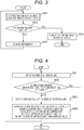
- Fig. 3 is a flowchart of refrigerant charging control processing performed by the control section 70a.
- the refrigerant charging control processing is processing executed during the refrigerant charging operation by the cooling operation as described above.
- the CPU 201 performs the control of balancing the refrigerant amount between the outdoor unit 10a and the outdoor unit 10b. Details of the processing of S301 will be described with reference to Figs. 4 and 5 etc. described later.
- the CPU 201 determines, after execution of later-described standby processing, whether or not the refrigerant amount (a charging amount) of the air-conditioning device is proper.
- the CPU 201 performs, as the standby processing, such control that the outdoor expansion valves 14a, 14b of the outdoor units 10a, 10b are substantially fixedly stabilized at a fixed opening degree (may be the maximum opening degree) and the rotation speeds (the air volumes) of the outdoor fans 15a, 15b are substantially fixedly stabilized at a value corresponding to a cycle state. More specifically, the CPU 201 stands by for a certain period of time. Then, in a stable state, the CPU 201 makes determination on the refrigerant amount of the air-conditioning device.
- the CPU 201 obtains an average temperature based on the temperature detected by the supercooling circuit outlet temperature sensor 60a of the outdoor unit 10a and a temperature detected by a supercooling circuit outlet temperature sensor 60b of the outdoor unit 10b, and based on whether or not the average temperature is equal to or lower than a preset threshold, determines whether or not the refrigerant amount of the air-conditioning device is proper. In a case where the average temperature is equal to or lower than the threshold, the CPU 201 determines that the refrigerant amount of the air-conditioning device is proper. On the other hand, in a case where the average temperature exceeds the threshold, the CPU 201 determines that the refrigerant amount of the air-conditioning device is not proper.
- the CPU 201 charges refrigerant to the refrigerant circuit.
- the CPU 201 sends the predetermined signal to the refrigerant charging electromagnetic valve 80a to open the refrigerant charging electromagnetic valve 80a for a predetermined period of time, thereby charging a predetermined amount of refrigerant to the refrigerant circuit.
- the predetermined period of time as described herein may be, for example, determined by the CPU 201 etc. according to an external air temperature.
- the predetermined amount is not limited to a fixed amount, and for example, may vary according to one or both of a refrigerant state in the cycle and a tank remaining amount.
- the CPU 201 returns to the processing of S301, and after the control of balancing the refrigerant amount has been performed, executes S302 to make determination on the refrigerant amount again.
- the CPU 201 displays, on the display section 204, that the amount of charged refrigerant is proper.
- the refrigerant charging control processing ends.
- refrigerant charging is completed.
- the worker detaches, for example, the charging hose from the refrigerant charging port 81a to terminate a refrigerant charging process.
- the amount of refrigerant in the outdoor heat exchanger is generally greater as a heat exchanger outlet specific enthalpy decreases, and is greater as the degree of supercooling increases. For this reason, operation is made such that the heat exchanger outlet specific enthalpy or the degree of supercooling is substantially equal among the multiple outdoor units, and therefore, the balance in the refrigerant amount among the multiple outdoor units can be maintained.
- a factor influencing the refrigerant state at an outlet of the outdoor heat exchanger is the rotation speed of the compressor.
- the degree of opening of the outdoor expansion valve also influences the refrigerant state at the outlet of the heat exchanger.
- the control section 70a of the first embodiment controls the rotation speed of the compressor providing greater influence to balance the refrigerant amount.
- Fig. 4 is a flowchart of one example of refrigerant amount balance control processing of the first embodiment.
- the CPU 201 obtains the degree of supercooling at the outlet of the supercooling circuit 20a of the outdoor unit 10a based on a difference between the temperature detected by the supercooling circuit outlet temperature sensor 60a of the outdoor unit 10a and a saturated temperature for the pressure detected by the high-pressure sensor 62a.
- the CPU 201 receives, via the control section 70b, the temperature detected by the supercooling circuit outlet temperature sensor 60b of the outdoor unit 10b and a saturated temperature for a pressure detected by a high-pressure sensor 62b.
- the CPU 201 obtains the degree of supercooling at an outlet of a supercooling circuit 20b of the outdoor unit 10b based on a difference between the temperature detected by the supercooling circuit outlet temperature sensor 60b and the saturated temperature for the pressure detected by the high-pressure sensor 62b.
- the CPU 201 of the control section 70b may obtain the degree of supercooling at the outlet of the supercooling circuit 20b in the outdoor unit 10b.
- the CPU 201 of the control section 70a may receive, from the control section 70b, the degree of supercooling at the outlet of the supercooling circuit 20b, the degree of supercooling being obtained by the control section 70b.
- the CPU 201 determines whether or not a difference between the degree of supercooling at the outlet of the supercooling circuit 20a of the outdoor unit 10a and the degree of supercooling at the outlet of the supercooling circuit 20b of the outdoor unit 10b is equal to or greater than a threshold. In a case where the CPU 201 determines that the difference is equal to or greater than the threshold, the processing proceeds to S403. In a case where the CPU 201 determines that the difference is less than the threshold, the refrigerant amount balance control processing ends.
- the CPU 201 obtains an average value of the degree of supercooling based on the degree of supercooling at the outlet of the supercooling circuit 20a of the outdoor unit 10a and the degree of supercooling at the outlet of the supercooling circuit 20b of the outdoor unit 10b.
- the average value is one example of a target value.
- the CPU 201 performs the control of decreasing the rotation speed of the compressor 11 of the outdoor unit 10 having a lower degree of supercooling than the average value and increasing the rotation speed of the compressor 11 of the outdoor unit 10 having a higher degree of supercooling than the average value.
- the degree of supercooling of the outdoor unit increases as the rotation speed of the compressor decreases, and decreases as the rotation speed of the compressor increases.
- a difference in the degree of supercooling among the multiple outdoor units can be decreased.
- the processing of S404 will be described in more details.
- the CPU 201 determines the rotation speed of each compressor 11 such that the increment of the rotation speed of the compressor 11 of the outdoor unit 10 having a higher degree of supercooling than the average value and the increment of the rotation speed of the compressor 11 of the outdoor unit 10 having a lower degree of supercooling than the average value are equal to each other.
- Examples of the increment and the increment are two hertzes (Hz). That is, the CPU 201 increases, by two hertzes, the rotation speed of the compressor 11 of the outdoor unit 10 having a higher degree of supercooling than the average value, and decreases, by two hertzes, the rotation speed of the compressor 11 of the outdoor unit 10 having a lower degree of supercooling than the average value.
- the amount of change in a frequency by the CPU 201 does not depend on the average value and the supercooling degree difference, and is fixed. After the processing of S404, the CPU 201 proceeds to S401.
- the degree of supercooling at the outlet of the supercooling circuit 20 is obtained based on the temperature at the outlet of the supercooling circuit 20, and therefore, the degree of supercooling can be properly obtained.
- the average value of the degree of supercooling is obtained, and the control of increasing the rotation speed of the compressor 11 of the outdoor unit 10 having a higher degree of supercooling than the average value and decreasing the rotation speed of the compressor 11 of the outdoor unit 10 having a lower degree of supercooling than the average value is performed.
- the refrigerant amount can be balanced among the outdoor units 10.
- the amount of refrigerant charged to the refrigerant circuit can be properly determined.
- a second embodiment will be described. Differences from the first embodiment will be mainly described herein.
- a factor influencing a refrigerant state at an outlet of an outdoor heat exchanger is an outdoor fan rotation speed in addition to a compressor rotation speed.
- a control section 70a of the second embodiment controls the outdoor fan rotation speed to balance a refrigerant amount.
- Fig. 5 is a flowchart of one example of refrigerant amount balance control processing of the second embodiment. Processing from S501 to S503 is similar to the processing from S401 to S403 in Fig. 4 , and therefore, description thereof will be omitted.
- a CPU 201 performs the control of increasing the fan rotation speed of an outdoor unit 10 having a lower degree of supercooling than an average value and decreasing the fan rotation speed of an outdoor unit 10 having a higher degree of supercooling than the average value.
- the degree of supercooling of the outdoor unit increases as the fan rotation speed increases, and decreases as the fan rotation speed decreases.
- the degree of supercooling among multiple outdoor units can be decreased.
- the processing of S504 will be more specifically described.
- the CPU 201 determines the rotation speed of each outdoor fan 15 such that the increment of the fan rotation speed of the outdoor fan 15 of the outdoor unit 10 having a lower degree of supercooling than the average value and the decrement of the fan rotation speed of the outdoor fan 15 of the outdoor unit 10 having a higher degree of supercooling than the average value are equal to each other.
- a relationship between the degree of supercooling and the rotation speed of the outdoor fan will be described herein.
- a heat transfer coefficient K increases, and therefore, a condensation capacity Qc increases.
- the rotation speed of the fan is controlled instead of the rotation speed of the compressor so that the refrigerant amount can be balanced among the outdoor units 10.
- the amount of refrigerant charged to a refrigerant circuit can be properly determined.
- FIG. 6 is a diagram of one example of an outline configuration of an air-conditioning device of the third embodiment.
- a configuration of an outdoor unit 100a will be described.
- the air-conditioning device of the third embodiment is different from the air-conditioning device of the first embodiment in that a supercooling circuit inlet temperature sensor 61a is provided at a pipe in the vicinity of an inlet of a supercooling circuit 20a in the outdoor unit 100a.
- a control section 70a of the third embodiment is connected to an outdoor fan 15a, a high-pressure sensor 62a, an outdoor expansion valve 14a, a supercooling expansion valve 23a, a supercooling circuit outlet temperature sensor 60a, a supercooling circuit inlet temperature sensor 61a, a compressor 11a, a refrigerant charging electromagnetic valve 80a, and a control section 70b of an outdoor unit 100b so that a signal can be transmitted or received through a signal line.
- the supercooling circuit inlet temperature sensor 61a detects the temperature of refrigerant at the pipe in the vicinity of the inlet of the supercooling circuit 20a.
- a configuration of the outdoor unit 100b is also similar to the configuration of the outdoor unit 100a.
- Fig. 7 is a flowchart of one example of refrigerant amount balance control of the third embodiment.
- a CPU 201 obtains a temperature difference between the inlet and an outlet of the supercooling circuit 20a based on the temperature detected by the supercooling circuit inlet temperature sensor 61a of the outdoor unit 100a and a temperature detected by the supercooling circuit outlet temperature sensor 60a of the outdoor unit 100a.
- the CPU 201 receives, via the control section 70b, a temperature detected by a supercooling circuit inlet temperature sensor 61b of the outdoor unit 100b and a temperature detected by a supercooling circuit outlet temperature sensor 60b of the outdoor unit 100b.
- the CPU 201 obtains a temperature difference between an inlet and an outlet of a supercooling circuit 20b based on the temperature detected by the supercooling circuit inlet temperature sensor 61b of the outdoor unit 100b and the temperature detected by the supercooling circuit outlet temperature sensor 60b of the outdoor unit 100b.
- a CPU 201 of the control section 70b may obtain the temperature difference between the inlet and the outlet of the supercooling circuit 20b based on the temperature detected by the supercooling circuit inlet temperature sensor 61b of the outdoor unit 100b and the temperature detected by the supercooling circuit outlet temperature sensor 60b of the outdoor unit 100b.
- the CPU 201 of the supercooling circuit 20a may receive, via the control section 70b, the temperature difference between the inlet and the outlet of the supercooling circuit 20b, the temperature difference being obtained by the control section 70b.
- the temperature difference between the inlet and the outlet of the supercooling circuit 20 is used in the third embodiment.
- the CPU 201 determines whether or not a difference between the temperature difference between the inlet and the outlet of the supercooling circuit 20a of the outdoor unit 100a and the temperature difference between the inlet and the outlet of the supercooling circuit 20b of the outdoor unit 100b is equal to or greater than a threshold. In a case where the CPU 201 determines that the difference is equal to or greater than the threshold, the processing proceeds to S703. In a case where the CPU 201 determines that the difference is less than the threshold, the refrigerant amount balance control processing illustrated in Fig. 7 ends.
- the CPU 201 obtains an average value of the temperature difference based on the temperature difference between the inlet and the outlet of the supercooling circuit 20a of the outdoor unit 100a and the temperature difference between the inlet and the outlet of the supercooling circuit 20b of the outdoor unit 100b.
- the average value is one example of a target value.
- the CPU 201 performs the control of decreasing the rotation speed of the compressor 11 of the outdoor unit 100 having a smaller temperature difference than the average value and increasing the rotation speed of the compressor 11 of the outdoor unit 100 having a greater temperature difference than the average value.
- the CPU 201 determines the rotation speed of each compressor 11 such that the total amount of the decrements of the rotation speeds of the compressors 11 of the outdoor units 100 having a smaller temperature difference than the average value and the total amount of the increments of the rotation speeds of the compressors 11 of the outdoor units 100 having a greater temperature difference than the average value are equal to each other.
- the CPU 201 proceeds to S701.
- the total amount is a preset value, and is two hertzes, for example.
- the temperature difference between the inlet and the outlet of the supercooling circuit 20 of the outdoor unit 100 can be utilized instead of the degree of supercooling. That is, according to the air-conditioning device of the third embodiment, the advantageous effects of the first embodiment can be also provided, and an error upon conversion into a saturated temperature can be reduced without the necessity of measuring a pressure by the high-pressure sensor 62 for further obtaining the degree of supercooling.
- a fourth embodiment will be described. Differences from the third embodiment will be mainly described herein.
- a control section 70a of the fourth embodiment controls an outdoor fan rotation speed to balance a refrigerant amount.
- Fig. 8 is a flowchart of one example of refrigerant amount balance control processing of the fourth embodiment. Processing from S801 to S803 is similar to the processing from S701 to S703 in Fig. 7 , and description thereof will be omitted.
- a CPU 201 performs the control of increasing the fan rotation speed of an outdoor unit 100 having a smaller temperature difference than an average value and decreasing the fan rotation speed of an outdoor unit 100 having a greater temperature difference than the average value.
- the CPU 201 determines the rotation speed of each outdoor fan 15 such that the increment of the fan rotation speed of the outdoor fan 15 of the outdoor unit 100 having a smaller temperature difference than the average value and the decrement of the fan rotation speed of the outdoor fan 15 of the outdoor unit 100 having a greater temperature difference than the average value are equal to each other.
- the temperature difference between an inlet and an outlet of the supercooling circuit 20 of the outdoor unit 100 can be utilized instead of the degree of supercooling. That is, according to the air-conditioning device of the fourth embodiment, the advantageous effects of the second embodiment can be also provided, and an error upon conversion into a saturated temperature can be reduced without the necessity of measuring a pressure by a high-pressure sensor 62 for further obtaining the degree of supercooling.
- the CPU 201 determines, for the degrees of supercooling of all outdoor units 10, whether or not a difference between the maximum value and the minimum value is equal to or greater than a threshold. In a case where the CPU 201 determines, for the degrees of supercooling of all outdoor units 10, that the difference between the maximum value and the minimum value is equal to or greater than the threshold, the processing proceeds to S403. In a case where the CPU 201 determines, for the degrees of supercooling of all outdoor units 10, that the difference between the maximum value and the minimum value is less than the threshold, the refrigerant amount balance control processing illustrated in Fig. 4 ends.
- the CPU 201 divides the preset increment (two hertzes) by the number of outdoor units 10 having a higher degree of supercooling than the average value, thereby determining the increment of each outdoor unit 10 having a higher degree. Similarly, the CPU 201 divides the preset decrement (two hertzes) by the number of outdoor units 10 having a lower degree of supercooling than the average value, thereby determining the decrement of each outdoor unit 10 having a lower degree.
- the increment of each outdoor unit 10 is one hertz.
- the total value of the increments and the total value of the decrements can be constantly held at two hertzes.
- the CPU 201 may further control the rotation speed of each compressor 11 based on the stroke volume of each compressor 11.
- the control section 70a may store the stroke volume of each compressor 11 in the storage section 202 in advance, or may make an inquiry to the control section 70 of each compressor 11 regarding the stroke volume of each compressor 11 to store, in the storage section 202, the stroke volume of each compressor 11 acquired as an inquiry result.
- the CPU 201 performs such control that the rotation speed of the compressor having a smaller stroke volume is slightly increased as compared to the rotation speed of the compressor having a greater stroke volume based on a reference stroke volume ratio and the rotation speed of the compressor having a greater stroke volume is slightly decreased as compared to the rotation speed of the compressor having a smaller stroke volume based on the reference stroke volume ratio.
- the CPU 201 performs such control that the rotation speed of the compressor having a smaller stroke volume is slightly increased with respect to one hertz and the rotation speed of the compressor having a greater stroke volume is slightly decreased with respect to one hertz.
- the CPU 201 also adjusts each of the total amount of the increments and the total amount of the decrements to two hertzes in reference stroke volume equivalent.
- the refrigerant amount balance control among the outdoor units can be performed considering the stroke volume of the compressor.
- the first embodiment has been described by way of example, but the same applies to other embodiments.
- the target value may be a value obtained based on multiple index values obtained for each of the multiple outdoor units, the target value is not limited to those of the embodiments. More preferably, the target value may be one of multiple index values between the maximum value and the minimum value. For example, the target value may be a medium value of the multiple index values. With this configuration, the refrigerant amount can be efficiently balanced.
- the outdoor unit 10a, the control section 70a of the outdoor unit 10a, etc. have been described as examples of the control device configured to perform the refrigerant charging control processing to control the air-conditioning device.
- the management device may perform the refrigerant charging control processing.
- the control device is not limited to the outdoor unit 10a.
- Other examples include an example where in a case where the air-conditioning device is communicably connected to an external device with or without wire, the external device may perform the refrigerant charging control processing.
- the supercooling bypass pipe 22a etc. have been described as examples of the cooling source of the supercooling circuit 20a. Note that an external heat source as the cooling source of the supercooling circuit 20a may be utilized.
- the amount of refrigerant charged to the refrigerant circuit can be properly determined.
Landscapes
- Engineering & Computer Science (AREA)
- Physics & Mathematics (AREA)
- Mechanical Engineering (AREA)
- Thermal Sciences (AREA)
- General Engineering & Computer Science (AREA)
- Air Conditioning Control Device (AREA)
Abstract
Description
- The present invention relates to a control device and an air-conditioning device.
- In the case of an air-conditioning device including multiple outdoor units, imbalance in a refrigerant amount in condensers of the outdoor units is caused upon determination on the refrigerant amount in refrigerant charging operation, and in some cases, a proper refrigerant amount for a refrigeration cycle cannot be determined.
- Patent Document 1 describes, as refrigerant amount balance control among the outdoor units, an example where the degree of supercooling at a condenser outlet of an outdoor unit is determined and a compressor rotation speed on a lower supercooling degree side is decreased as compared to a compressor rotation speed on a higher supercooling degree side and an example where a fan rotation speed on the lower supercooling degree side is increased as compared to a fan rotation speed on the higher supercooling degree side.
- In Patent Document 1, a refrigerant amount in refrigerant charging operation is determined using the degree of supercooling at the condenser outlet of the outdoor unit, assuming that the degree of supercooling can be properly obtained at the condenser outlet of each outdoor unit. However, when refrigerant at the condenser outlet of the outdoor unit is in a two-phase state, no temperature change is shown. Thus, even with a refrigerant specific enthalpy change, such a refrigerant specific enthalpy change cannot be determined, and the degree of supercooling at the condenser outlet of the outdoor unit cannot be properly obtained. As a result, there is a problem that the refrigerant amount in the refrigerant charging operation cannot be properly determined.
- For this reason, the present invention is intended to properly determine the amount of refrigerant charged to a refrigerant circuit.
- The present invention relates to a control device of an air-conditioning device including multiple outdoor units and an indoor unit connected to the multiple outdoor units through a pipe. The control device includes a control section configured to obtain, before refrigerant charging to a refrigerant circuit including the multiple outdoor units and the indoor unit is completed, the degree of supercooling at an outlet of a supercooling circuit of each outdoor unit based on a temperature detected by a temperature sensor configured to detect the temperature of refrigerant having passed through the supercooling circuit of each outdoor unit, obtain a target value of the degree of supercooling based on the obtained multiple degrees of supercooling, and perform the control of increasing the rotation speed of a compressor of an outdoor unit having a higher degree of supercooling than the target value and decreasing the rotation speed of a compressor of an outdoor unit having a lower degree of supercooling than the target value such that a difference in the degree of supercooling at the outlet of the supercooling circuit of each outdoor unit is decreased.
- According to the present invention, the amount of refrigerant charged to the refrigerant circuit can be properly determined.
-
-
Fig. 1 is a diagram of one example of an outline configuration of an air-conditioning device of a first embodiment. -
Fig. 2 is a diagram of one example of a hardware configuration of a control section. -
Fig. 3 is a flowchart of one example of information processing. -
Fig. 4 is a flowchart of one example of refrigerant amount balance control processing of the first embodiment. -
Fig. 5 is a flowchart of one example of refrigerant amount balance control processing of a second embodiment. -
Fig. 6 is a diagram of one example of an outline configuration of an air-conditioning device of a third embodiment. -
Fig. 7 is a flowchart of one example of refrigerant amount balance control processing of the third embodiment. -
Fig. 8 is a flowchart of one example of refrigerant amount balance control processing of a fourth embodiment. - Hereinafter, embodiments of the present invention will be described with reference to the drawings.
- A first embodiment will be described.
Fig. 1 is a diagram of one example of an outline configuration of an air-conditioning device of the first embodiment. The air-conditioning device is configured such thatoutdoor units 10a, 10b andindoor units liquid pipe 31 and agas pipe 30 to form a closed circuit. The closed circuit is sealed with refrigerant, and the refrigerant circulates to implement a refrigeration cycle. The number of connected outdoor units 10 described herein may be two or more as long as multiple units are provided. The number of connected indoor units 40 may be one. Theoutdoor unit 10a is one example of a control device of the air-conditioning device. - First, a configuration of the
outdoor unit 10a will be described. Theoutdoor unit 10a is configured such that acompressor 11a whose rotation frequency is variable by an inverter, a four-way valve (a reversible valve) 12a, anoutdoor heat exchanger 13a configured to exchange heat with outdoor air, anoutdoor expansion valve 14a including an electronic expansion valve etc. for adjusting the flow rate of refrigerant in theoutdoor heat exchanger 13a, asupercooling circuit 20a, agas blocking valve 16a, aliquid blocking valve 17a, etc. are connected to each other through a pipe. Moreover, asupercooling bypass pipe 22a as a cooling source of thesupercooling circuit 20a is provided at theoutdoor unit 10a. Thesupercooling bypass pipe 22a is provided such that part of refrigerant sent from theoutdoor expansion valve 14a to theliquid pipe 31 returns to thecompressor 11a. More specifically, thesupercooling bypass pipe 22a extends from between theoutdoor expansion valve 14a and thesupercooling circuit 20a, and is connected to a suction port side of thecompressor 11a through thesupercooling circuit 20a. Further, asupercooling expansion valve 23a configured to adjust the flow rate of refrigerant flowing in thesupercooling bypass pipe 22a is provided at thesupercooling bypass pipe 22a. - A supercooling circuit
outlet temperature sensor 60a is provided at the pipe in the vicinity of an outlet of thesupercooling circuit 20a. The supercooling circuitoutlet temperature sensor 60a detects the temperature of refrigerant at the pipe in the vicinity of the outlet of thesupercooling circuit 20a. Moreover, arefrigerant charging port 81a as a refrigerant charging opening is provided at thesupercooling bypass pipe 22a, and a refrigerant chargingelectromagnetic valve 80a for refrigerant charging is provided downstream of therefrigerant charging port 81a. Upon charging, a refrigerant tank sealed with refrigerant is connected to therefrigerant charging port 81a through a charging hose. Moreover, a high-pressure sensor 62a configured to detect the pressure of gas refrigerant discharged from thecompressor 11a is provided at the discharge-side pipe of thecompressor 11a. - Moreover, a
control section 70a configured to control operation of theoutdoor unit 10a is provided at theoutdoor unit 10a. Thecontrol section 70a is connected to anoutdoor fan 15a, the high-pressure sensor 62a, theoutdoor expansion valve 14a, thesupercooling expansion valve 23a, the supercooling circuitoutlet temperature sensor 60a, thecompressor 11a, the refrigerant chargingelectromagnetic valve 80a, and acontrol section 70b of the outdoor unit 10b so that a signal can be transmitted or received through a signal line. A configuration of the outdoor unit 10b is also similar to the configuration of theoutdoor unit 10a. Hereinafter, description will be made assuming that thecontrol section 70a also transmits a signal to thecontrol section 70b and also control the outdoor unit 10b via thecontrol section 70b. - Next, a configuration of the
indoor unit 40a will be described. Theindoor unit 40a is configured such that anindoor heat exchanger 41a configured to exchange heat with indoor air and anindoor expansion valve 42a including an electronic expansion valve etc. for adjusting the flow rate of refrigerant in theindoor heat exchanger 41a are connected to each other through a pipe. Configurations of theindoor unit 40b, theindoor unit 40c, and theindoor unit 40d are similar to the configuration of theindoor unit 40a. -
Fig. 2 is a diagram of one example of a hardware configuration of thecontrol section 70a. Thecontrol section 70a includes aCPU 201, astorage section 202, aninput section 203, adisplay section 204, and acommunication section 205. TheCPU 201 reads a program stored in thestorage section 202 to execute processing. Thestorage section 202 is used as a primary storage area, such as a main memory or a working area, upon execution of the processing by theCPU 201, and stores data (e.g., each threshold described later), programs, etc. used upon execution of the processing by theCPU 201. Thestorage section 202 is one example of a storage medium. Theinput section 203 is, for example, a button, and receives operation by a user to input such operation to theCPU 201. Thedisplay section 204 is, for example, a display, and displays a result of the processing by theCPU 201. Thecommunication section 205 communicates with the outdoor unit 10b etc. via the signal line. The functions and processing of thecontrol section 70a are implemented in such a manner that theCPU 201 executes the processing based on the programs stored in thestorage section 202. Part of the functions and processing of thecontrol section 70a may be, as another example, implemented using a hardware circuit. A hardware configuration of thecontrol section 70b is also similar to the hardware configuration of thecontrol section 70a. - The
control section 70a according to the first embodiment performs the processing of balancing a refrigerant amount between theoutdoor units 10a, 10b upon refrigerant charging for the air-conditioning device. Upon refrigerant charging, it is necessary to determine whether or not the amount of refrigerant charged to the air-conditioning device is proper. Upon determination on the refrigerant amount, the refrigerant amount needs to be balanced between theoutdoor units 10a, 10b. However, in some cases, the balance in the refrigerant amount between the outdoor units is not achieved due to an external factor etc. On the other hand, the air-conditioning device of the present embodiment adjusts the balance in the refrigerant amount by the control of thecontrol section 70a, and in a state in which a proper balance in the refrigerant amount is achieved, determines whether or not the refrigerant amount is proper. - Refrigerant charging will be described in advance of the processing of the
control section 70a. First, theoutdoor units 10a, 10b and theindoor units 40a to 40d are placed, and are connected to each other through thegas pipe 30 and theliquid pipe 31. Note that theoutdoor units 10a, 10b are sealed with a predetermined amount of refrigerant. After vacuuming has been performed for the inside of the refrigerant pipe on a side close to theindoor units 40a to 40d, thegas blocking valves liquid blocking valves outdoor units 10a, 10b are opened, and a refrigerant circuit is filled with the refrigerant sealed in theoutdoor units 10a, 10b. - Next, for charging refrigerant, a worker connects the
refrigerant charging port 81a of theoutdoor unit 10a and the refrigerant tank sealed with refrigerant to each other through the charging hose. After completion of connection, the worker performs the operation of starting refrigerant charging operation for theinput section 203 with a valve of the refrigerant tank being opened. When the operation of starting the refrigerant charging operation for theinput section 203 is performed, theoutdoor units 10a, 10b start the refrigerant charging operation by a signal of theCPU 201. When it is, during the refrigerant charging operation, determined that refrigerant charging is necessary, theCPU 201 transmits a predetermined signal to the refrigerant chargingelectromagnetic valve 80a. When receiving the predetermined signal, the refrigerant chargingelectromagnetic valve 80a opens. When the refrigerant chargingelectromagnetic valve 80a is opened with the valve of the refrigerant tank being opened, the refrigerant circuit is filled with the refrigerant of the refrigerant tank. - In the air-conditioning device of the first embodiment, refrigerant is charged when cooling operation is performed for the
outdoor units 10a, 10b and theindoor units outdoor units 10a, 10b and thecompressors way valves gas pipe 30 and a compressor suction pipe are connected to each other and theoutdoor heat exchangers outdoor units 10a, 10b, and therefore, theoutdoor unit 10a will be described as a representative. High-pressure gas refrigerant compressed in thecompressor 11a is sent to the four-way valve 12a and theoutdoor heat exchanger 13a, and then, by heat exchange with outdoor suction air, is condensed into high-pressure liquid refrigerant. Then, such refrigerant passes through theoutdoor expansion valve 14a. At this point, liquid pressure is slightly decreased due to resistance of the expansion valve. Then, the refrigerant is branched into thesupercooling bypass pipe 22a and thesupercooling circuit 20a. The bypassed liquid refrigerant is depressurized in thesupercooling expansion valve 23a, and by heat exchange with the remaining unbypassed liquid refrigerant, is gasified and sent to a compressor suction side. Meanwhile, the unbypassed liquid refrigerant is cooled in thesupercooling circuit 20a, and is sent to a supercoolingcircuit outlet pipe 21a and theliquid pipe 31. Similarly, high-pressure liquid refrigerant is also sent from the outdoor unit 10b to theliquid pipe 31, and joins the unbypassed liquid refrigerant. The refrigerant is used for the cooling operation in each of theindoor units outdoor units 10a, 10b through thegas pipe 30, and is compressed and circulates again. -
Fig. 3 is a flowchart of refrigerant charging control processing performed by thecontrol section 70a. The refrigerant charging control processing is processing executed during the refrigerant charging operation by the cooling operation as described above. - At S301, the
CPU 201 performs the control of balancing the refrigerant amount between theoutdoor unit 10a and the outdoor unit 10b. Details of the processing of S301 will be described with reference toFigs. 4 and5 etc. described later. - At S302, the
CPU 201 determines, after execution of later-described standby processing, whether or not the refrigerant amount (a charging amount) of the air-conditioning device is proper. TheCPU 201 performs, as the standby processing, such control that theoutdoor expansion valves outdoor units 10a, 10b are substantially fixedly stabilized at a fixed opening degree (may be the maximum opening degree) and the rotation speeds (the air volumes) of theoutdoor fans CPU 201 stands by for a certain period of time. Then, in a stable state, theCPU 201 makes determination on the refrigerant amount of the air-conditioning device. TheCPU 201 obtains an average temperature based on the temperature detected by the supercooling circuitoutlet temperature sensor 60a of theoutdoor unit 10a and a temperature detected by a supercooling circuitoutlet temperature sensor 60b of the outdoor unit 10b, and based on whether or not the average temperature is equal to or lower than a preset threshold, determines whether or not the refrigerant amount of the air-conditioning device is proper. In a case where the average temperature is equal to or lower than the threshold, theCPU 201 determines that the refrigerant amount of the air-conditioning device is proper. On the other hand, in a case where the average temperature exceeds the threshold, theCPU 201 determines that the refrigerant amount of the air-conditioning device is not proper. When theCPU 201 determines that the refrigerant amount of the air-conditioning device is not proper (insufficient), the processing proceeds to S303. When theCPU 201 determines that the refrigerant amount of the air-conditioning device is proper, the processing proceeds to S304. - At S303, the
CPU 201 charges refrigerant to the refrigerant circuit. TheCPU 201 sends the predetermined signal to the refrigerant chargingelectromagnetic valve 80a to open the refrigerant chargingelectromagnetic valve 80a for a predetermined period of time, thereby charging a predetermined amount of refrigerant to the refrigerant circuit. The predetermined period of time as described herein may be, for example, determined by theCPU 201 etc. according to an external air temperature. Moreover, the predetermined amount is not limited to a fixed amount, and for example, may vary according to one or both of a refrigerant state in the cycle and a tank remaining amount. Then, theCPU 201 returns to the processing of S301, and after the control of balancing the refrigerant amount has been performed, executes S302 to make determination on the refrigerant amount again. - At S304, the
CPU 201 displays, on thedisplay section 204, that the amount of charged refrigerant is proper. When theCPU 201 displays, on thedisplay section 204, that the amount of charged refrigerant is proper, the refrigerant charging control processing ends. When the refrigerant charging control processing ends, refrigerant charging is completed. In a case where thedisplay section 204 displays that the amount of charged refrigerant is proper, the worker detaches, for example, the charging hose from therefrigerant charging port 81a to terminate a refrigerant charging process. - Next, the principle of balancing the refrigerant amount between the outdoor units will be described. First, the amount of refrigerant in the outdoor heat exchanger is generally greater as a heat exchanger outlet specific enthalpy decreases, and is greater as the degree of supercooling increases. For this reason, operation is made such that the heat exchanger outlet specific enthalpy or the degree of supercooling is substantially equal among the multiple outdoor units, and therefore, the balance in the refrigerant amount among the multiple outdoor units can be maintained. A factor influencing the refrigerant state at an outlet of the outdoor heat exchanger is the rotation speed of the compressor. The degree of opening of the outdoor expansion valve also influences the refrigerant state at the outlet of the heat exchanger. However, the
control section 70a of the first embodiment controls the rotation speed of the compressor providing greater influence to balance the refrigerant amount. -
Fig. 4 is a flowchart of one example of refrigerant amount balance control processing of the first embodiment. At S401, theCPU 201 obtains the degree of supercooling at the outlet of thesupercooling circuit 20a of theoutdoor unit 10a based on a difference between the temperature detected by the supercooling circuitoutlet temperature sensor 60a of theoutdoor unit 10a and a saturated temperature for the pressure detected by the high-pressure sensor 62a. Moreover, theCPU 201 receives, via thecontrol section 70b, the temperature detected by the supercooling circuitoutlet temperature sensor 60b of the outdoor unit 10b and a saturated temperature for a pressure detected by a high-pressure sensor 62b. Then, theCPU 201 obtains the degree of supercooling at an outlet of asupercooling circuit 20b of the outdoor unit 10b based on a difference between the temperature detected by the supercooling circuitoutlet temperature sensor 60b and the saturated temperature for the pressure detected by the high-pressure sensor 62b. Note that theCPU 201 of thecontrol section 70b may obtain the degree of supercooling at the outlet of thesupercooling circuit 20b in the outdoor unit 10b. Then, theCPU 201 of thecontrol section 70a may receive, from thecontrol section 70b, the degree of supercooling at the outlet of thesupercooling circuit 20b, the degree of supercooling being obtained by thecontrol section 70b. - At S402, the
CPU 201 determines whether or not a difference between the degree of supercooling at the outlet of thesupercooling circuit 20a of theoutdoor unit 10a and the degree of supercooling at the outlet of thesupercooling circuit 20b of the outdoor unit 10b is equal to or greater than a threshold. In a case where theCPU 201 determines that the difference is equal to or greater than the threshold, the processing proceeds to S403. In a case where theCPU 201 determines that the difference is less than the threshold, the refrigerant amount balance control processing ends. - At S403, the
CPU 201 obtains an average value of the degree of supercooling based on the degree of supercooling at the outlet of thesupercooling circuit 20a of theoutdoor unit 10a and the degree of supercooling at the outlet of thesupercooling circuit 20b of the outdoor unit 10b. The average value is one example of a target value. - At S404, the
CPU 201 performs the control of decreasing the rotation speed of the compressor 11 of the outdoor unit 10 having a lower degree of supercooling than the average value and increasing the rotation speed of the compressor 11 of the outdoor unit 10 having a higher degree of supercooling than the average value. Although the principle thereof will be described later, the degree of supercooling of the outdoor unit increases as the rotation speed of the compressor decreases, and decreases as the rotation speed of the compressor increases. Thus, by the present processing, a difference in the degree of supercooling among the multiple outdoor units can be decreased. - The processing of S404 will be described in more details. The
CPU 201 determines the rotation speed of each compressor 11 such that the increment of the rotation speed of the compressor 11 of the outdoor unit 10 having a higher degree of supercooling than the average value and the increment of the rotation speed of the compressor 11 of the outdoor unit 10 having a lower degree of supercooling than the average value are equal to each other. Examples of the increment and the increment are two hertzes (Hz). That is, theCPU 201 increases, by two hertzes, the rotation speed of the compressor 11 of the outdoor unit 10 having a higher degree of supercooling than the average value, and decreases, by two hertzes, the rotation speed of the compressor 11 of the outdoor unit 10 having a lower degree of supercooling than the average value. The amount of change in a frequency by theCPU 201 does not depend on the average value and the supercooling degree difference, and is fixed. After the processing of S404, theCPU 201 proceeds to S401. - A relationship between the degree of supercooling and the rotation speed of the compressor will be described herein. As the rotation speed of the compressor decreases, only a refrigerant circulation amount Gr decreases with almost no change in a heat exchange amount Qc = KA (Tc - Ta) obtained from an air side, and therefore, Hi - Ho increases. An outdoor heat exchanger inlet refrigerant specific enthalpy Hi shows little change, and therefore, an outdoor heat exchanger outlet refrigerant specific enthalpy Ho decreases (see Expression 1). That is, a supercooling circuit inlet refrigerant specific enthalpy decreases (Hsi = Ho), and therefore, in the case of a fixed supercooling circuit capacity Qsc, a supercooling circuit outlet refrigerant specific enthalpy Hso also decreases (see Expression 2). That is, the degree of supercooling increases. Conversely, as the rotation speed of the compressor increases, the degree of supercooling decreases.

- K: heat transfer coefficient ... changeable according to outdoor fan air volume and to outdoor heat exchanger specifications;
- A: outdoor heat exchanger heat transfer area;
- Tc: condensation temperature ... substantially equal to saturated temperature for discharge pressure;
- Ta: external air temperature;
- Gr: refrigerant circulation amount... changeable according to compressor rotation speed and sucked refrigerant state;
- Hi: outdoor heat exchanger inlet refrigerant specific enthalpy; and
- Ho: outdoor heat exchanger outlet refrigerant specific enthalpy.
- Hsi: supercooling circuit inlet refrigerant specific enthalpy; and
- Hso: supercooling circuit outlet refrigerant specific enthalpy.
- According to the air-conditioning device of the first embodiment, the degree of supercooling at the outlet of the supercooling circuit 20 is obtained based on the temperature at the outlet of the supercooling circuit 20, and therefore, the degree of supercooling can be properly obtained. Moreover, according to the air-conditioning device of the first embodiment, the average value of the degree of supercooling is obtained, and the control of increasing the rotation speed of the compressor 11 of the outdoor unit 10 having a higher degree of supercooling than the average value and decreasing the rotation speed of the compressor 11 of the outdoor unit 10 having a lower degree of supercooling than the average value is performed. With this configuration, the refrigerant amount can be balanced among the outdoor units 10. Thus, according to the air-conditioning device of the first embodiment, the amount of refrigerant charged to the refrigerant circuit can be properly determined.
- A second embodiment will be described. Differences from the first embodiment will be mainly described herein. A factor influencing a refrigerant state at an outlet of an outdoor heat exchanger is an outdoor fan rotation speed in addition to a compressor rotation speed. A
control section 70a of the second embodiment controls the outdoor fan rotation speed to balance a refrigerant amount. -
Fig. 5 is a flowchart of one example of refrigerant amount balance control processing of the second embodiment. Processing from S501 to S503 is similar to the processing from S401 to S403 inFig. 4 , and therefore, description thereof will be omitted. At S504, aCPU 201 performs the control of increasing the fan rotation speed of an outdoor unit 10 having a lower degree of supercooling than an average value and decreasing the fan rotation speed of an outdoor unit 10 having a higher degree of supercooling than the average value. Although the principle thereof will be described later, the degree of supercooling of the outdoor unit increases as the fan rotation speed increases, and decreases as the fan rotation speed decreases. Thus, according to the present processing, the degree of supercooling among multiple outdoor units can be decreased. - The processing of S504 will be more specifically described. The
CPU 201 determines the rotation speed of each outdoor fan 15 such that the increment of the fan rotation speed of the outdoor fan 15 of the outdoor unit 10 having a lower degree of supercooling than the average value and the decrement of the fan rotation speed of the outdoor fan 15 of the outdoor unit 10 having a higher degree of supercooling than the average value are equal to each other. - A relationship between the degree of supercooling and the rotation speed of the outdoor fan will be described herein. As the rotation speed of the outdoor fan increases, a heat transfer coefficient K increases, and therefore, a condensation capacity Qc increases. A refrigerant circulation amount Gr and a condenser inlet refrigerant specific enthalpy Hi show little change, and therefore, a condenser outlet refrigerant specific enthalpy Ho decreases (see Expression 1). That is, a supercooling circuit inlet refrigerant specific enthalpy decreases (Hsi = Ho), and therefore, in the case of a fixed supercooling circuit capacity Qsc, a supercooling circuit outlet refrigerant specific enthalpy Hso also decreases (see Expression 2). That is, the degree of supercooling increases. Conversely, as the rotation speed of the outdoor fan decreases, the degree of supercooling decreases.
- According to an air-conditioning device of the second embodiment, the rotation speed of the fan is controlled instead of the rotation speed of the compressor so that the refrigerant amount can be balanced among the outdoor units 10. Thus, according to the air-conditioning device of the second embodiment, the amount of refrigerant charged to a refrigerant circuit can be properly determined.
- A third embodiment will be described. Differences from the above-described embodiments will be mainly described herein.
Fig. 6 is a diagram of one example of an outline configuration of an air-conditioning device of the third embodiment. A configuration of anoutdoor unit 100a will be described. The air-conditioning device of the third embodiment is different from the air-conditioning device of the first embodiment in that a supercooling circuitinlet temperature sensor 61a is provided at a pipe in the vicinity of an inlet of asupercooling circuit 20a in theoutdoor unit 100a. Acontrol section 70a of the third embodiment is connected to anoutdoor fan 15a, a high-pressure sensor 62a, anoutdoor expansion valve 14a, asupercooling expansion valve 23a, a supercooling circuitoutlet temperature sensor 60a, a supercooling circuitinlet temperature sensor 61a, acompressor 11a, a refrigerant chargingelectromagnetic valve 80a, and acontrol section 70b of anoutdoor unit 100b so that a signal can be transmitted or received through a signal line. The supercooling circuitinlet temperature sensor 61a detects the temperature of refrigerant at the pipe in the vicinity of the inlet of thesupercooling circuit 20a. A configuration of theoutdoor unit 100b is also similar to the configuration of theoutdoor unit 100a. -
Fig. 7 is a flowchart of one example of refrigerant amount balance control of the third embodiment. At S701, aCPU 201 obtains a temperature difference between the inlet and an outlet of thesupercooling circuit 20a based on the temperature detected by the supercooling circuitinlet temperature sensor 61a of theoutdoor unit 100a and a temperature detected by the supercooling circuitoutlet temperature sensor 60a of theoutdoor unit 100a. Moreover, theCPU 201 receives, via thecontrol section 70b, a temperature detected by a supercooling circuitinlet temperature sensor 61b of theoutdoor unit 100b and a temperature detected by a supercooling circuitoutlet temperature sensor 60b of theoutdoor unit 100b. Then, theCPU 201 obtains a temperature difference between an inlet and an outlet of asupercooling circuit 20b based on the temperature detected by the supercooling circuitinlet temperature sensor 61b of theoutdoor unit 100b and the temperature detected by the supercooling circuitoutlet temperature sensor 60b of theoutdoor unit 100b. Note that aCPU 201 of thecontrol section 70b may obtain the temperature difference between the inlet and the outlet of thesupercooling circuit 20b based on the temperature detected by the supercooling circuitinlet temperature sensor 61b of theoutdoor unit 100b and the temperature detected by the supercooling circuitoutlet temperature sensor 60b of theoutdoor unit 100b. Then, theCPU 201 of thesupercooling circuit 20a may receive, via thecontrol section 70b, the temperature difference between the inlet and the outlet of thesupercooling circuit 20b, the temperature difference being obtained by thecontrol section 70b. Instead of the degree of supercooling at the outlet of the supercooling circuit 20 as described in the first embodiment, the temperature difference between the inlet and the outlet of the supercooling circuit 20 is used in the third embodiment. - At S702, the
CPU 201 determines whether or not a difference between the temperature difference between the inlet and the outlet of thesupercooling circuit 20a of theoutdoor unit 100a and the temperature difference between the inlet and the outlet of thesupercooling circuit 20b of theoutdoor unit 100b is equal to or greater than a threshold. In a case where theCPU 201 determines that the difference is equal to or greater than the threshold, the processing proceeds to S703. In a case where theCPU 201 determines that the difference is less than the threshold, the refrigerant amount balance control processing illustrated inFig. 7 ends. - At S703, the
CPU 201 obtains an average value of the temperature difference based on the temperature difference between the inlet and the outlet of thesupercooling circuit 20a of theoutdoor unit 100a and the temperature difference between the inlet and the outlet of thesupercooling circuit 20b of theoutdoor unit 100b. The average value is one example of a target value. - At S704, the
CPU 201 performs the control of decreasing the rotation speed of the compressor 11 of the outdoor unit 100 having a smaller temperature difference than the average value and increasing the rotation speed of the compressor 11 of the outdoor unit 100 having a greater temperature difference than the average value. TheCPU 201 determines the rotation speed of each compressor 11 such that the total amount of the decrements of the rotation speeds of the compressors 11 of the outdoor units 100 having a smaller temperature difference than the average value and the total amount of the increments of the rotation speeds of the compressors 11 of the outdoor units 100 having a greater temperature difference than the average value are equal to each other. After the processing of S704, theCPU 201 proceeds to S701. The total amount is a preset value, and is two hertzes, for example. - According to the air-conditioning device of the third embodiment, the temperature difference between the inlet and the outlet of the supercooling circuit 20 of the outdoor unit 100 can be utilized instead of the degree of supercooling. That is, according to the air-conditioning device of the third embodiment, the advantageous effects of the first embodiment can be also provided, and an error upon conversion into a saturated temperature can be reduced without the necessity of measuring a pressure by the high-pressure sensor 62 for further obtaining the degree of supercooling.
- A fourth embodiment will be described. Differences from the third embodiment will be mainly described herein. A
control section 70a of the fourth embodiment controls an outdoor fan rotation speed to balance a refrigerant amount.Fig. 8 is a flowchart of one example of refrigerant amount balance control processing of the fourth embodiment. Processing from S801 to S803 is similar to the processing from S701 to S703 inFig. 7 , and description thereof will be omitted. At S804, aCPU 201 performs the control of increasing the fan rotation speed of an outdoor unit 100 having a smaller temperature difference than an average value and decreasing the fan rotation speed of an outdoor unit 100 having a greater temperature difference than the average value. - More specifically, the
CPU 201 determines the rotation speed of each outdoor fan 15 such that the increment of the fan rotation speed of the outdoor fan 15 of the outdoor unit 100 having a smaller temperature difference than the average value and the decrement of the fan rotation speed of the outdoor fan 15 of the outdoor unit 100 having a greater temperature difference than the average value are equal to each other. - According to the air-conditioning device of the fourth embodiment, the temperature difference between an inlet and an outlet of the supercooling circuit 20 of the outdoor unit 100 can be utilized instead of the degree of supercooling. That is, according to the air-conditioning device of the fourth embodiment, the advantageous effects of the second embodiment can be also provided, and an error upon conversion into a saturated temperature can be reduced without the necessity of measuring a pressure by a high-pressure sensor 62 for further obtaining the degree of supercooling.
- The case of three or more units will be described. At S402, the
CPU 201 determines, for the degrees of supercooling of all outdoor units 10, whether or not a difference between the maximum value and the minimum value is equal to or greater than a threshold. In a case where theCPU 201 determines, for the degrees of supercooling of all outdoor units 10, that the difference between the maximum value and the minimum value is equal to or greater than the threshold, the processing proceeds to S403. In a case where theCPU 201 determines, for the degrees of supercooling of all outdoor units 10, that the difference between the maximum value and the minimum value is less than the threshold, the refrigerant amount balance control processing illustrated inFig. 4 ends. - At S404, the
CPU 201 divides the preset increment (two hertzes) by the number of outdoor units 10 having a higher degree of supercooling than the average value, thereby determining the increment of each outdoor unit 10 having a higher degree. Similarly, theCPU 201 divides the preset decrement (two hertzes) by the number of outdoor units 10 having a lower degree of supercooling than the average value, thereby determining the decrement of each outdoor unit 10 having a lower degree. - For example, in a case where the number of outdoor units 10 having a higher degree is two and the number of outdoor units 10 having a lower degree is one, the increment of each outdoor unit 10 is one hertz. With this configuration, the total value of the increments and the total value of the decrements can be constantly held at two hertzes.
- A second variation will be described. The
CPU 201 may further control the rotation speed of each compressor 11 based on the stroke volume of each compressor 11. Thecontrol section 70a may store the stroke volume of each compressor 11 in thestorage section 202 in advance, or may make an inquiry to the control section 70 of each compressor 11 regarding the stroke volume of each compressor 11 to store, in thestorage section 202, the stroke volume of each compressor 11 acquired as an inquiry result. In the case of increasing the compressor rotation speed by the same change amount, theCPU 201 performs such control that the rotation speed of the compressor having a smaller stroke volume is slightly increased as compared to the rotation speed of the compressor having a greater stroke volume based on a reference stroke volume ratio and the rotation speed of the compressor having a greater stroke volume is slightly decreased as compared to the rotation speed of the compressor having a smaller stroke volume based on the reference stroke volume ratio. For example, even in a case where the rotation speeds of two compressors are both to be increased by one hertz, theCPU 201 performs such control that the rotation speed of the compressor having a smaller stroke volume is slightly increased with respect to one hertz and the rotation speed of the compressor having a greater stroke volume is slightly decreased with respect to one hertz. In this case, theCPU 201 also adjusts each of the total amount of the increments and the total amount of the decrements to two hertzes in reference stroke volume equivalent. - According to the air-conditioning device of the second variation, the refrigerant amount balance control among the outdoor units can be performed considering the stroke volume of the compressor. In the second variation, the first embodiment has been described by way of example, but the same applies to other embodiments.
- A third variation will be described. In the above-described embodiments, description has been made using the average value of the supercooling degree or the temperature difference (hereinafter referred to as an "index value") as the example of the target value. As long as the target value may be a value obtained based on multiple index values obtained for each of the multiple outdoor units, the target value is not limited to those of the embodiments. More preferably, the target value may be one of multiple index values between the maximum value and the minimum value. For example, the target value may be a medium value of the multiple index values. With this configuration, the refrigerant amount can be efficiently balanced.
- A fourth variation will be described. In each of the above-described embodiments, the
outdoor unit 10a, thecontrol section 70a of theoutdoor unit 10a, etc. have been described as examples of the control device configured to perform the refrigerant charging control processing to control the air-conditioning device. Note that in a case where the air-conditioning device further has a management device configured to manage the indoor unit and the outdoor unit, the management device may perform the refrigerant charging control processing. As described above, the control device is not limited to theoutdoor unit 10a. Other examples include an example where in a case where the air-conditioning device is communicably connected to an external device with or without wire, the external device may perform the refrigerant charging control processing. - A fifth variation will be described. In each of the above-described embodiments, the supercooling
bypass pipe 22a etc. have been described as examples of the cooling source of thesupercooling circuit 20a. Note that an external heat source as the cooling source of thesupercooling circuit 20a may be utilized. - As described above, according to each of the above-described embodiments, the amount of refrigerant charged to the refrigerant circuit can be properly determined.
- As described above, the example embodiments of the present invention have been described in detail, but the present invention is not limited to these specific embodiments.

Claims (17)
- A control device of an air-conditioning device including multiple outdoor units and an indoor unit connected to the multiple outdoor units through a pipe, comprising:
a control section configured to obtain, before refrigerant charging to a refrigerant circuit including the multiple outdoor units and the indoor unit is completed, a degree of supercooling at an outlet of a supercooling circuit of each outdoor unit based on a temperature detected by a temperature sensor configured to detect a temperature of refrigerant having passed through the supercooling circuit of each outdoor unit, obtain a target value of the degree of supercooling based on the obtained multiple degrees of supercooling, and perform a control of increasing a rotation speed of a compressor of an outdoor unit having a higher degree of supercooling than the target value and decreasing a rotation speed of a compressor of an outdoor unit having a lower degree of supercooling than the target value such that a difference in the degree of supercooling at the outlet of the supercooling circuit of each outdoor unit is decreased. - A control device of an air-conditioning device including multiple outdoor units and an indoor unit connected to the multiple outdoor units through a pipe, comprising:
a control section configured to obtain, before refrigerant charging to a refrigerant circuit including the multiple outdoor units and the indoor unit is completed, a degree of supercooling at an outlet of a supercooling circuit of each outdoor unit based on a temperature detected by a temperature sensor configured to detect a temperature of refrigerant having passed through the supercooling circuit of each outdoor unit, obtain a target value of the degree of supercooling based on the obtained multiple degrees of supercooling, and perform a control of decreasing a rotation speed of a fan of a heat exchanger of an outdoor unit having a higher degree of supercooling than the target value and increasing a rotation speed of a fan of a heat exchanger of an outdoor unit having a lower degree of supercooling than the target value such that a difference in the degree of supercooling at the outlet of the supercooling circuit of each outdoor unit is decreased. - A control device of an air-conditioning device including multiple outdoor units and an indoor unit connected to the multiple outdoor units through a pipe, comprising:
a control section configured to obtain, before refrigerant charging to a refrigerant circuit including the multiple outdoor units and the indoor unit is completed, a refrigerant temperature difference between an inlet and an outlet of a supercooling circuit of each outdoor unit based on a temperature detected by a first temperature sensor configured to detect a temperature of refrigerant having passed through the supercooling circuit of each outdoor unit and a temperature detected by a second temperature sensor configured to detect a temperature of refrigerant before the refrigerant passes through the supercooling circuit of each outdoor unit, obtain a target value of the temperature difference based on the obtained multiple refrigerant temperature differences, and perform a control of increasing a rotation speed of a compressor of an outdoor unit having a greater temperature difference than the target value and decreasing a rotation speed of a compressor of an outdoor unit having a smaller temperature difference than the target value such that a difference in the refrigerant temperature difference between the inlet and the outlet of the supercooling circuit of each outdoor unit is decreased. - A control device of an air-conditioning device including multiple outdoor units and an indoor unit connected to the multiple outdoor units through a pipe, comprising:
a control section configured to obtain, before refrigerant charging to a refrigerant circuit including the multiple outdoor units and the indoor unit is completed, a refrigerant temperature difference between an inlet and an outlet of a supercooling circuit of each outdoor unit based on a temperature detected by a first temperature sensor configured to detect a temperature of refrigerant having passed through the supercooling circuit of each outdoor unit and a temperature detected by a second temperature sensor configured to detect a temperature of refrigerant before the refrigerant passes through the supercooling circuit of each outdoor unit, obtain a target value of the temperature difference based on the obtained multiple refrigerant temperature differences, and perform a control of decreasing a rotation speed of a fan of a heat exchanger of an outdoor unit having a greater temperature difference than the target value and increasing a rotation speed of a fan of a heat exchanger of an outdoor unit having a smaller temperature difference than the target value such that a difference in the refrigerant temperature difference between the inlet and the outlet of the supercooling circuit of each outdoor unit is decreased. - The control device according to any one of claims 1 to 4, wherein
the control section determines, after the control, whether or not an amount of refrigerant charged to the refrigerant circuit is proper. - The control device according to claim 1 or 3, wherein
the control section determines the rotation speed of each compressor such that a total amount of increments of rotation speeds of compressors of outdoor units having a higher degree of supercooling than the target value and a total amount of decrements of rotation speeds of compressors of outdoor units having a lower degree of supercooling than the target value are equal to each other. - The control device according to claim 6, wherein
the total amount is a preset value. - The control device according to claim 6 or 7, wherein
the control section determines the rotation speed of each compressor based on the number of compressors. - The control device according to any one of claims 6 to 8, wherein
the control section determines the rotation speed of each compressor based on a stroke volume of each compressor. - The control device according to claim 1 or 2, wherein
the control section obtains, as the target value, an average value of the degrees of supercooling based on the obtained multiple degrees of supercooling. - The control device according to claim 3 or 4, wherein
the control section obtains, as the target value, an average value of the temperature differences based on the obtained multiple temperature differences. - The control device according to claim 1 or 2, whereinthe control section determines, for the obtained multiple degrees of supercooling, whether or not the difference is equal to or greater than a threshold, andin a case where it is, for the obtained multiple degrees of supercooling, determined that the difference is equal to or greater than the threshold, the target value of the degree of supercooling is obtained based on the obtained multiple degrees of supercooling.
- The control device according to claim 3 or 4, whereinthe control section determines, for the obtained multiple temperature differences, whether or not the difference is equal to or greater than a threshold, andin a case where it is, for the obtained multiple temperature differences, determined that the difference is equal to or greater than the threshold, the target value of the temperature difference is obtained based on the obtained multiple temperature differences.
- An air-conditioning device including multiple outdoor units and an indoor unit connected to the multiple outdoor units through a pipe, comprising:
a control section configured to obtain, before refrigerant charging to a refrigerant circuit including the multiple outdoor units and the indoor unit is completed, a degree of supercooling at an outlet of a supercooling circuit of each outdoor unit based on a temperature detected by a temperature sensor configured to detect a temperature of refrigerant having passed through the supercooling circuit of each outdoor unit, obtain a target value of the degree of supercooling based on the obtained multiple degrees of supercooling, and perform a control of increasing a rotation speed of a compressor of an outdoor unit having a higher degree of supercooling than the target value and decreasing a rotation speed of a compressor of an outdoor unit having a lower degree of supercooling than the target value such that a difference in the degree of supercooling at the outlet of the supercooling circuit of each outdoor unit is decreased. - An air-conditioning device including multiple outdoor units and an indoor unit connected to the multiple outdoor units through a pipe, comprising:
a control section configured to obtain, before refrigerant charging to a refrigerant circuit including the multiple outdoor units and the indoor unit is completed, a degree of supercooling at an outlet of a supercooling circuit of each outdoor unit based on a temperature detected by a temperature sensor configured to detect a temperature of refrigerant having passed through the supercooling circuit of each outdoor unit, obtain a target value of the degree of supercooling based on the obtained multiple degrees of supercooling, and perform a control of decreasing a rotation speed of a fan of a heat exchanger of an outdoor unit having a higher degree of supercooling than the target value and increasing a rotation speed of a fan of a heat exchanger of an outdoor unit having a lower degree of supercooling than the target value such that a difference in the degree of supercooling at the outlet of the supercooling circuit of each outdoor unit is decreased. - An air-conditioning device including multiple outdoor units and an indoor unit connected to the multiple outdoor units through a pipe, comprising:
a control section configured to obtain, before refrigerant charging to a refrigerant circuit including the multiple outdoor units and the indoor unit is completed, a refrigerant temperature difference between an inlet and an outlet of a supercooling circuit of each outdoor unit based on a temperature detected by a first temperature sensor configured to detect a temperature of refrigerant having passed through the supercooling circuit of each outdoor unit and a temperature detected by a second temperature sensor configured to detect a temperature of refrigerant before the refrigerant passes through the supercooling circuit of each outdoor unit, obtain a target value of the temperature difference based on the obtained multiple refrigerant temperature differences, and perform a control of increasing a rotation speed of a compressor of an outdoor unit having a greater temperature difference than the target value and decreasing a rotation speed of a compressor of an outdoor unit having a smaller temperature difference than the target value such that a difference in the refrigerant temperature difference between the inlet and the outlet of the supercooling circuit of each outdoor unit is decreased. - An air-conditioning device including multiple outdoor units and an indoor unit connected to the multiple outdoor units through a pipe, comprising:
a control section configured to obtain, before refrigerant charging to a refrigerant circuit including the multiple outdoor units and the indoor unit is completed, a refrigerant temperature difference between an inlet and an outlet of a supercooling circuit of each outdoor unit based on a temperature detected by a first temperature sensor configured to detect a temperature of refrigerant having passed through the supercooling circuit of each outdoor unit and a temperature detected by a second temperature sensor configured to detect a temperature of refrigerant before the refrigerant passes through the supercooling circuit of each outdoor unit, obtain a target value of the temperature difference based on the obtained multiple refrigerant temperature differences, and perform a control of decreasing a rotation speed of a fan of a heat exchanger of an outdoor unit having a greater temperature difference than the target value and increasing a rotation speed of a fan of a heat exchanger of an outdoor unit having a smaller temperature difference than the target value such that a difference in the refrigerant temperature difference between the inlet and the outlet of the supercooling circuit of each outdoor unit is decreased.
Applications Claiming Priority (1)
| Application Number | Priority Date | Filing Date | Title |
|---|---|---|---|
| PCT/JP2018/044169 WO2020110289A1 (en) | 2018-11-30 | 2018-11-30 | Control device and air conditioning device |
Publications (3)
| Publication Number | Publication Date |
|---|---|
| EP3889521A1 true EP3889521A1 (en) | 2021-10-06 |
| EP3889521A4 EP3889521A4 (en) | 2022-10-12 |
| EP3889521B1 EP3889521B1 (en) | 2024-08-28 |
Family
ID=67614803
Family Applications (1)
| Application Number | Title | Priority Date | Filing Date |
|---|---|---|---|
| EP18867314.9A Active EP3889521B1 (en) | 2018-11-30 | 2018-11-30 | Control device and air conditioning device |
Country Status (5)
| Country | Link |
|---|---|
| US (1) | US11204188B2 (en) |
| EP (1) | EP3889521B1 (en) |
| JP (1) | JP6557918B1 (en) |
| CN (1) | CN111512102B (en) |
| WO (1) | WO2020110289A1 (en) |
Families Citing this family (3)
| Publication number | Priority date | Publication date | Assignee | Title |
|---|---|---|---|---|
| CN112797680A (en) * | 2020-12-31 | 2021-05-14 | 珠海格力电器股份有限公司 | Control device, method and system for automatically filling refrigerant and air conditioning equipment |
| CN114061107B (en) * | 2021-12-27 | 2023-11-28 | 上海美控智慧建筑有限公司 | Control method and system of multi-split air conditioning system |
| CN115111743B (en) * | 2022-06-06 | 2025-06-17 | 青岛海尔空调器有限总公司 | Control method and device of outdoor unit and air conditioner |
Family Cites Families (23)
| Publication number | Priority date | Publication date | Assignee | Title |
|---|---|---|---|---|
| JPH0599540A (en) * | 1991-10-03 | 1993-04-20 | Zexel Corp | Refrigerant overfill prevention device for vehicle air conditioner |
| JP3601130B2 (en) * | 1995-10-06 | 2004-12-15 | 株式会社デンソー | Refrigeration equipment |
| CN100356116C (en) * | 2003-03-28 | 2007-12-19 | 东芝开利株式会社 | Air conditioner |
| US7472557B2 (en) * | 2004-12-27 | 2009-01-06 | Carrier Corporation | Automatic refrigerant charging apparatus |
| JP4120682B2 (en) * | 2006-02-20 | 2008-07-16 | ダイキン工業株式会社 | Air conditioner and heat source unit |
| JP4285583B2 (en) * | 2007-05-30 | 2009-06-24 | ダイキン工業株式会社 | Air conditioner |
| JP4803237B2 (en) | 2007-05-30 | 2011-10-26 | ダイキン工業株式会社 | Air conditioner |
| JPWO2010007730A1 (en) * | 2008-07-18 | 2012-01-05 | パナソニック株式会社 | Refrigeration cycle equipment |
| WO2010023894A1 (en) * | 2008-08-28 | 2010-03-04 | ダイキン工業株式会社 | Air-conditioning device |
| JP5582773B2 (en) * | 2009-12-10 | 2014-09-03 | 三菱重工業株式会社 | Air conditioner and refrigerant amount detection method for air conditioner |
| JP5352512B2 (en) * | 2010-03-31 | 2013-11-27 | 日立アプライアンス株式会社 | Air conditioner |
| JP5610843B2 (en) * | 2010-05-24 | 2014-10-22 | 三菱電機株式会社 | Air conditioner |
| JP5525965B2 (en) * | 2010-08-25 | 2014-06-18 | 日立アプライアンス株式会社 | Refrigeration cycle equipment |
| JP5516712B2 (en) * | 2012-05-28 | 2014-06-11 | ダイキン工業株式会社 | Refrigeration equipment |
| JP6313950B2 (en) | 2013-10-23 | 2018-04-18 | 日立ジョンソンコントロールズ空調株式会社 | Air conditioner |
| KR102243860B1 (en) * | 2014-04-22 | 2021-04-23 | 엘지전자 주식회사 | A control method for an air conditioner |
| JP6242321B2 (en) * | 2014-10-03 | 2017-12-06 | 三菱電機株式会社 | Air conditioner |
| JP6366741B2 (en) * | 2015-01-23 | 2018-08-01 | 三菱電機株式会社 | Air conditioner |
| JP6642903B2 (en) * | 2015-03-31 | 2020-02-12 | 三菱重工サーマルシステムズ株式会社 | Refrigerant circulating device, refrigerant circulating method, refrigerant charging method, and operating method of refrigerant circulating device |
| CN106882007A (en) * | 2015-12-16 | 2017-06-23 | 杭州三花研究院有限公司 | A kind of air-conditioning system, control device and its control method |
| JP6569536B2 (en) * | 2016-01-08 | 2019-09-04 | 株式会社富士通ゼネラル | Air conditioner |
| WO2017195248A1 (en) * | 2016-05-09 | 2017-11-16 | 三菱電機株式会社 | Refrigeration device |
| CN106839340A (en) * | 2017-03-16 | 2017-06-13 | 广东美的制冷设备有限公司 | A kind of air conditioner refrigerating measuring method, device and air-conditioner |
-
2018
- 2018-11-30 CN CN201880019142.9A patent/CN111512102B/en active Active
- 2018-11-30 JP JP2019511510A patent/JP6557918B1/en active Active
- 2018-11-30 EP EP18867314.9A patent/EP3889521B1/en active Active
- 2018-11-30 WO PCT/JP2018/044169 patent/WO2020110289A1/en not_active Ceased
-
2019
- 2019-06-18 US US16/444,162 patent/US11204188B2/en active Active
Also Published As
| Publication number | Publication date |
|---|---|
| EP3889521B1 (en) | 2024-08-28 |
| WO2020110289A1 (en) | 2020-06-04 |
| EP3889521A4 (en) | 2022-10-12 |
| JPWO2020110289A1 (en) | 2021-02-15 |
| CN111512102B (en) | 2022-01-28 |
| US20200173694A1 (en) | 2020-06-04 |
| CN111512102A (en) | 2020-08-07 |
| JP6557918B1 (en) | 2019-08-14 |
| US11204188B2 (en) | 2021-12-21 |
Similar Documents
| Publication | Publication Date | Title |
|---|---|---|
| US11131490B2 (en) | Refrigeration device having condenser unit connected to compressor unit with on-site pipe interposed therebetween and remote from the compressor unit | |
| EP3859247B1 (en) | Air-conditioning device | |
| EP2829823B1 (en) | Refrigeration cycle apparatus | |
| EP2375188B1 (en) | Air conditioner | |
| EP2088391B1 (en) | Method for determining the amount of refrigerant of air-conditioning apparatus | |
| EP2677251B1 (en) | Refrigeration cycle device and refrigeration cycle control method | |
| EP3885670B1 (en) | Refrigeration cycle apparatus | |
| EP3889523A1 (en) | Refrigerant leakage determination system and refrigeration cycle device | |
| EP3088819B1 (en) | Air conditioning device | |
| WO2014097282A2 (en) | Refrigerant charge assisting device, air-conditioning apparatus, and refrigerant charge assisting program | |
| US20190376727A1 (en) | Air conditioner | |
| EP3889521B1 (en) | Control device and air conditioning device | |
| EP3312528A1 (en) | Air conditioner | |
| WO2018062485A1 (en) | Refrigerant amount determination method and refrigerant amount determination device | |
| EP2878899B1 (en) | Air conditioner | |
| JP2010266190A (en) | Heat source unit | |
| JP2021156532A (en) | Air conditioner | |
| JP2008298335A (en) | Refrigeration apparatus, additional refrigerant filling kit used for the refrigeration apparatus, and additional refrigerant charging method for refrigeration apparatus | |
| US10077930B2 (en) | Air-conditioning apparatus and air-conditioning system | |
| EP3282208A1 (en) | Refrigeration apparatus | |
| JP6537629B2 (en) | Air conditioner | |
| EP4343235A1 (en) | Refrigerant leakage detection system | |
| EP4191164B1 (en) | Air conditioner | |
| JP5573741B2 (en) | Air conditioner | |
| JP7150192B2 (en) | Outdoor unit and refrigeration cycle equipment |
Legal Events
| Date | Code | Title | Description |
|---|---|---|---|
| STAA | Information on the status of an ep patent application or granted ep patent |
Free format text: STATUS: UNKNOWN |
|
| STAA | Information on the status of an ep patent application or granted ep patent |
Free format text: STATUS: THE INTERNATIONAL PUBLICATION HAS BEEN MADE |
|
| PUAI | Public reference made under article 153(3) epc to a published international application that has entered the european phase |
Free format text: ORIGINAL CODE: 0009012 |
|
| STAA | Information on the status of an ep patent application or granted ep patent |
Free format text: STATUS: REQUEST FOR EXAMINATION WAS MADE |
|
| 17P | Request for examination filed |
Effective date: 20200630 |
|
| AK | Designated contracting states |
Kind code of ref document: A1 Designated state(s): AL AT BE BG CH CY CZ DE DK EE ES FI FR GB GR HR HU IE IS IT LI LT LU LV MC MK MT NL NO PL PT RO RS SE SI SK SM TR |
|
| DAV | Request for validation of the european patent (deleted) | ||
| DAX | Request for extension of the european patent (deleted) | ||
| RIC1 | Information provided on ipc code assigned before grant |
Ipc: F25B 45/00 20060101AFI20220525BHEP |
|
| A4 | Supplementary search report drawn up and despatched |
Effective date: 20220909 |
|
| RIC1 | Information provided on ipc code assigned before grant |
Ipc: F25B 45/00 20060101AFI20220905BHEP |
|
| GRAP | Despatch of communication of intention to grant a patent |
Free format text: ORIGINAL CODE: EPIDOSNIGR1 |
|
| STAA | Information on the status of an ep patent application or granted ep patent |
Free format text: STATUS: GRANT OF PATENT IS INTENDED |
|
| INTG | Intention to grant announced |
Effective date: 20240321 |
|
| GRAS | Grant fee paid |
Free format text: ORIGINAL CODE: EPIDOSNIGR3 |
|
| GRAA | (expected) grant |
Free format text: ORIGINAL CODE: 0009210 |
|
| STAA | Information on the status of an ep patent application or granted ep patent |
Free format text: STATUS: THE PATENT HAS BEEN GRANTED |
|
| AK | Designated contracting states |
Kind code of ref document: B1 Designated state(s): AL AT BE BG CH CY CZ DE DK EE ES FI FR GB GR HR HU IE IS IT LI LT LU LV MC MK MT NL NO PL PT RO RS SE SI SK SM TR |
|
| REG | Reference to a national code |
Ref country code: GB Ref legal event code: FG4D |
|
| REG | Reference to a national code |
Ref country code: CH Ref legal event code: EP |
|
| REG | Reference to a national code |
Ref country code: DE Ref legal event code: R096 Ref document number: 602018073767 Country of ref document: DE |
|
| REG | Reference to a national code |
Ref country code: IE Ref legal event code: FG4D |
|
| REG | Reference to a national code |
Ref country code: LT Ref legal event code: MG9D |
|
| PG25 | Lapsed in a contracting state [announced via postgrant information from national office to epo] |
Ref country code: NO Free format text: LAPSE BECAUSE OF FAILURE TO SUBMIT A TRANSLATION OF THE DESCRIPTION OR TO PAY THE FEE WITHIN THE PRESCRIBED TIME-LIMIT Effective date: 20241128 |
|
| REG | Reference to a national code |
Ref country code: AT Ref legal event code: MK05 Ref document number: 1718337 Country of ref document: AT Kind code of ref document: T Effective date: 20240828 |
|
| PG25 | Lapsed in a contracting state [announced via postgrant information from national office to epo] |
Ref country code: NL Free format text: LAPSE BECAUSE OF FAILURE TO SUBMIT A TRANSLATION OF THE DESCRIPTION OR TO PAY THE FEE WITHIN THE PRESCRIBED TIME-LIMIT Effective date: 20240828 Ref country code: GR Free format text: LAPSE BECAUSE OF FAILURE TO SUBMIT A TRANSLATION OF THE DESCRIPTION OR TO PAY THE FEE WITHIN THE PRESCRIBED TIME-LIMIT Effective date: 20241129 Ref country code: PL Free format text: LAPSE BECAUSE OF FAILURE TO SUBMIT A TRANSLATION OF THE DESCRIPTION OR TO PAY THE FEE WITHIN THE PRESCRIBED TIME-LIMIT Effective date: 20240828 Ref country code: PT Free format text: LAPSE BECAUSE OF FAILURE TO SUBMIT A TRANSLATION OF THE DESCRIPTION OR TO PAY THE FEE WITHIN THE PRESCRIBED TIME-LIMIT Effective date: 20241230 Ref country code: FI Free format text: LAPSE BECAUSE OF FAILURE TO SUBMIT A TRANSLATION OF THE DESCRIPTION OR TO PAY THE FEE WITHIN THE PRESCRIBED TIME-LIMIT Effective date: 20240828 |
|
| PG25 | Lapsed in a contracting state [announced via postgrant information from national office to epo] |
Ref country code: BG Free format text: LAPSE BECAUSE OF FAILURE TO SUBMIT A TRANSLATION OF THE DESCRIPTION OR TO PAY THE FEE WITHIN THE PRESCRIBED TIME-LIMIT Effective date: 20240828 |
|
| PG25 | Lapsed in a contracting state [announced via postgrant information from national office to epo] |
Ref country code: LV Free format text: LAPSE BECAUSE OF FAILURE TO SUBMIT A TRANSLATION OF THE DESCRIPTION OR TO PAY THE FEE WITHIN THE PRESCRIBED TIME-LIMIT Effective date: 20240828 |
|
| REG | Reference to a national code |
Ref country code: NL Ref legal event code: MP Effective date: 20240828 |
|
| PG25 | Lapsed in a contracting state [announced via postgrant information from national office to epo] |
Ref country code: AT Free format text: LAPSE BECAUSE OF FAILURE TO SUBMIT A TRANSLATION OF THE DESCRIPTION OR TO PAY THE FEE WITHIN THE PRESCRIBED TIME-LIMIT Effective date: 20240828 Ref country code: IS Free format text: LAPSE BECAUSE OF FAILURE TO SUBMIT A TRANSLATION OF THE DESCRIPTION OR TO PAY THE FEE WITHIN THE PRESCRIBED TIME-LIMIT Effective date: 20241228 |
|
| PG25 | Lapsed in a contracting state [announced via postgrant information from national office to epo] |
Ref country code: HR Free format text: LAPSE BECAUSE OF FAILURE TO SUBMIT A TRANSLATION OF THE DESCRIPTION OR TO PAY THE FEE WITHIN THE PRESCRIBED TIME-LIMIT Effective date: 20240828 |
|
| PG25 | Lapsed in a contracting state [announced via postgrant information from national office to epo] |
Ref country code: ES Free format text: LAPSE BECAUSE OF FAILURE TO SUBMIT A TRANSLATION OF THE DESCRIPTION OR TO PAY THE FEE WITHIN THE PRESCRIBED TIME-LIMIT Effective date: 20240828 Ref country code: RS Free format text: LAPSE BECAUSE OF FAILURE TO SUBMIT A TRANSLATION OF THE DESCRIPTION OR TO PAY THE FEE WITHIN THE PRESCRIBED TIME-LIMIT Effective date: 20241128 |
|
| PG25 | Lapsed in a contracting state [announced via postgrant information from national office to epo] |
Ref country code: RS Free format text: LAPSE BECAUSE OF FAILURE TO SUBMIT A TRANSLATION OF THE DESCRIPTION OR TO PAY THE FEE WITHIN THE PRESCRIBED TIME-LIMIT Effective date: 20241128 Ref country code: PT Free format text: LAPSE BECAUSE OF FAILURE TO SUBMIT A TRANSLATION OF THE DESCRIPTION OR TO PAY THE FEE WITHIN THE PRESCRIBED TIME-LIMIT Effective date: 20241230 Ref country code: PL Free format text: LAPSE BECAUSE OF FAILURE TO SUBMIT A TRANSLATION OF THE DESCRIPTION OR TO PAY THE FEE WITHIN THE PRESCRIBED TIME-LIMIT Effective date: 20240828 Ref country code: NO Free format text: LAPSE BECAUSE OF FAILURE TO SUBMIT A TRANSLATION OF THE DESCRIPTION OR TO PAY THE FEE WITHIN THE PRESCRIBED TIME-LIMIT Effective date: 20241128 Ref country code: NL Free format text: LAPSE BECAUSE OF FAILURE TO SUBMIT A TRANSLATION OF THE DESCRIPTION OR TO PAY THE FEE WITHIN THE PRESCRIBED TIME-LIMIT Effective date: 20240828 Ref country code: LV Free format text: LAPSE BECAUSE OF FAILURE TO SUBMIT A TRANSLATION OF THE DESCRIPTION OR TO PAY THE FEE WITHIN THE PRESCRIBED TIME-LIMIT Effective date: 20240828 Ref country code: IS Free format text: LAPSE BECAUSE OF FAILURE TO SUBMIT A TRANSLATION OF THE DESCRIPTION OR TO PAY THE FEE WITHIN THE PRESCRIBED TIME-LIMIT Effective date: 20241228 Ref country code: HR Free format text: LAPSE BECAUSE OF FAILURE TO SUBMIT A TRANSLATION OF THE DESCRIPTION OR TO PAY THE FEE WITHIN THE PRESCRIBED TIME-LIMIT Effective date: 20240828 Ref country code: GR Free format text: LAPSE BECAUSE OF FAILURE TO SUBMIT A TRANSLATION OF THE DESCRIPTION OR TO PAY THE FEE WITHIN THE PRESCRIBED TIME-LIMIT Effective date: 20241129 Ref country code: FI Free format text: LAPSE BECAUSE OF FAILURE TO SUBMIT A TRANSLATION OF THE DESCRIPTION OR TO PAY THE FEE WITHIN THE PRESCRIBED TIME-LIMIT Effective date: 20240828 Ref country code: ES Free format text: LAPSE BECAUSE OF FAILURE TO SUBMIT A TRANSLATION OF THE DESCRIPTION OR TO PAY THE FEE WITHIN THE PRESCRIBED TIME-LIMIT Effective date: 20240828 Ref country code: BG Free format text: LAPSE BECAUSE OF FAILURE TO SUBMIT A TRANSLATION OF THE DESCRIPTION OR TO PAY THE FEE WITHIN THE PRESCRIBED TIME-LIMIT Effective date: 20240828 Ref country code: AT Free format text: LAPSE BECAUSE OF FAILURE TO SUBMIT A TRANSLATION OF THE DESCRIPTION OR TO PAY THE FEE WITHIN THE PRESCRIBED TIME-LIMIT Effective date: 20240828 |
|
| PG25 | Lapsed in a contracting state [announced via postgrant information from national office to epo] |
Ref country code: RO Free format text: LAPSE BECAUSE OF FAILURE TO SUBMIT A TRANSLATION OF THE DESCRIPTION OR TO PAY THE FEE WITHIN THE PRESCRIBED TIME-LIMIT Effective date: 20240828 Ref country code: DK Free format text: LAPSE BECAUSE OF FAILURE TO SUBMIT A TRANSLATION OF THE DESCRIPTION OR TO PAY THE FEE WITHIN THE PRESCRIBED TIME-LIMIT Effective date: 20240828 Ref country code: SM Free format text: LAPSE BECAUSE OF FAILURE TO SUBMIT A TRANSLATION OF THE DESCRIPTION OR TO PAY THE FEE WITHIN THE PRESCRIBED TIME-LIMIT Effective date: 20240828 |
|
| PG25 | Lapsed in a contracting state [announced via postgrant information from national office to epo] |
Ref country code: EE Free format text: LAPSE BECAUSE OF FAILURE TO SUBMIT A TRANSLATION OF THE DESCRIPTION OR TO PAY THE FEE WITHIN THE PRESCRIBED TIME-LIMIT Effective date: 20240828 |
|
| PG25 | Lapsed in a contracting state [announced via postgrant information from national office to epo] |
Ref country code: CZ Free format text: LAPSE BECAUSE OF FAILURE TO SUBMIT A TRANSLATION OF THE DESCRIPTION OR TO PAY THE FEE WITHIN THE PRESCRIBED TIME-LIMIT Effective date: 20240828 |
|
| PG25 | Lapsed in a contracting state [announced via postgrant information from national office to epo] |
Ref country code: IT Free format text: LAPSE BECAUSE OF FAILURE TO SUBMIT A TRANSLATION OF THE DESCRIPTION OR TO PAY THE FEE WITHIN THE PRESCRIBED TIME-LIMIT Effective date: 20240828 Ref country code: SK Free format text: LAPSE BECAUSE OF FAILURE TO SUBMIT A TRANSLATION OF THE DESCRIPTION OR TO PAY THE FEE WITHIN THE PRESCRIBED TIME-LIMIT Effective date: 20240828 |
|
| REG | Reference to a national code |
Ref country code: DE Ref legal event code: R097 Ref document number: 602018073767 Country of ref document: DE |
|
| REG | Reference to a national code |
Ref country code: DE Ref legal event code: R119 Ref document number: 602018073767 Country of ref document: DE |
|
| REG | Reference to a national code |
Ref country code: CH Ref legal event code: PL |
|
| PLBE | No opposition filed within time limit |
Free format text: ORIGINAL CODE: 0009261 |
|
| STAA | Information on the status of an ep patent application or granted ep patent |
Free format text: STATUS: NO OPPOSITION FILED WITHIN TIME LIMIT |
|
| PG25 | Lapsed in a contracting state [announced via postgrant information from national office to epo] |
Ref country code: MC Free format text: LAPSE BECAUSE OF FAILURE TO SUBMIT A TRANSLATION OF THE DESCRIPTION OR TO PAY THE FEE WITHIN THE PRESCRIBED TIME-LIMIT Effective date: 20240828 |
|
| PG25 | Lapsed in a contracting state [announced via postgrant information from national office to epo] |
Ref country code: LU Free format text: LAPSE BECAUSE OF NON-PAYMENT OF DUE FEES Effective date: 20241130 |
|
| REG | Reference to a national code |
Ref country code: CH Ref legal event code: PL |
|
| GBPC | Gb: european patent ceased through non-payment of renewal fee |
Effective date: 20241130 |
|
| PG25 | Lapsed in a contracting state [announced via postgrant information from national office to epo] |
Ref country code: CH Free format text: LAPSE BECAUSE OF NON-PAYMENT OF DUE FEES Effective date: 20241130 |
|
| 26N | No opposition filed |
Effective date: 20250530 |
|
| REG | Reference to a national code |
Ref country code: BE Ref legal event code: MM Effective date: 20241130 |
|
| PG25 | Lapsed in a contracting state [announced via postgrant information from national office to epo] |
Ref country code: SE Free format text: LAPSE BECAUSE OF FAILURE TO SUBMIT A TRANSLATION OF THE DESCRIPTION OR TO PAY THE FEE WITHIN THE PRESCRIBED TIME-LIMIT Effective date: 20240828 |
|
| PG25 | Lapsed in a contracting state [announced via postgrant information from national office to epo] |
Ref country code: DE Free format text: LAPSE BECAUSE OF NON-PAYMENT OF DUE FEES Effective date: 20250603 |
|
| PG25 | Lapsed in a contracting state [announced via postgrant information from national office to epo] |
Ref country code: GB Free format text: LAPSE BECAUSE OF NON-PAYMENT OF DUE FEES Effective date: 20241130 Ref country code: BE Free format text: LAPSE BECAUSE OF NON-PAYMENT OF DUE FEES Effective date: 20241130 |
|
| PG25 | Lapsed in a contracting state [announced via postgrant information from national office to epo] |
Ref country code: FR Free format text: LAPSE BECAUSE OF NON-PAYMENT OF DUE FEES Effective date: 20241130 |
|
| PG25 | Lapsed in a contracting state [announced via postgrant information from national office to epo] |
Ref country code: IE Free format text: LAPSE BECAUSE OF NON-PAYMENT OF DUE FEES Effective date: 20241130 |
|
| PG25 | Lapsed in a contracting state [announced via postgrant information from national office to epo] |
Ref country code: CY Free format text: LAPSE BECAUSE OF FAILURE TO SUBMIT A TRANSLATION OF THE DESCRIPTION OR TO PAY THE FEE WITHIN THE PRESCRIBED TIME-LIMIT; INVALID AB INITIO Effective date: 20181130 |
|
| PG25 | Lapsed in a contracting state [announced via postgrant information from national office to epo] |
Ref country code: TR Free format text: LAPSE BECAUSE OF FAILURE TO SUBMIT A TRANSLATION OF THE DESCRIPTION OR TO PAY THE FEE WITHIN THE PRESCRIBED TIME-LIMIT Effective date: 20240828 |
|
| PG25 | Lapsed in a contracting state [announced via postgrant information from national office to epo] |
Ref country code: HU Free format text: LAPSE BECAUSE OF FAILURE TO SUBMIT A TRANSLATION OF THE DESCRIPTION OR TO PAY THE FEE WITHIN THE PRESCRIBED TIME-LIMIT; INVALID AB INITIO Effective date: 20181130 |
|
| PG25 | Lapsed in a contracting state [announced via postgrant information from national office to epo] |
Ref country code: SI Free format text: LAPSE BECAUSE OF FAILURE TO SUBMIT A TRANSLATION OF THE DESCRIPTION OR TO PAY THE FEE WITHIN THE PRESCRIBED TIME-LIMIT Effective date: 20240828 |
|
| PG25 | Lapsed in a contracting state [announced via postgrant information from national office to epo] |
Ref country code: LT Free format text: LAPSE BECAUSE OF FAILURE TO SUBMIT A TRANSLATION OF THE DESCRIPTION OR TO PAY THE FEE WITHIN THE PRESCRIBED TIME-LIMIT Effective date: 20240828 |