EP3889467B1 - Method for changing over transmission stages of a transmission arrangement - Google Patents
Method for changing over transmission stages of a transmission arrangement Download PDFInfo
- Publication number
- EP3889467B1 EP3889467B1 EP21165428.0A EP21165428A EP3889467B1 EP 3889467 B1 EP3889467 B1 EP 3889467B1 EP 21165428 A EP21165428 A EP 21165428A EP 3889467 B1 EP3889467 B1 EP 3889467B1
- Authority
- EP
- European Patent Office
- Prior art keywords
- hydraulic machine
- transmission
- zero
- expulsion volume
- transmission stage
- Prior art date
- Legal status (The legal status is an assumption and is not a legal conclusion. Google has not performed a legal analysis and makes no representation as to the accuracy of the status listed.)
- Active
Links
Images


Classifications
-
- F—MECHANICAL ENGINEERING; LIGHTING; HEATING; WEAPONS; BLASTING
- F16—ENGINEERING ELEMENTS AND UNITS; GENERAL MEASURES FOR PRODUCING AND MAINTAINING EFFECTIVE FUNCTIONING OF MACHINES OR INSTALLATIONS; THERMAL INSULATION IN GENERAL
- F16H—GEARING
- F16H61/00—Control functions within control units of change-speed- or reversing-gearings for conveying rotary motion ; Control of exclusively fluid gearing, friction gearing, gearings with endless flexible members or other particular types of gearing
- F16H61/02—Control functions within control units of change-speed- or reversing-gearings for conveying rotary motion ; Control of exclusively fluid gearing, friction gearing, gearings with endless flexible members or other particular types of gearing characterised by the signals used
- F16H61/0202—Control functions within control units of change-speed- or reversing-gearings for conveying rotary motion ; Control of exclusively fluid gearing, friction gearing, gearings with endless flexible members or other particular types of gearing characterised by the signals used the signals being electric
- F16H61/0248—Control units where shifting is directly initiated by the driver, e.g. semi-automatic transmissions
-
- F—MECHANICAL ENGINEERING; LIGHTING; HEATING; WEAPONS; BLASTING
- F16—ENGINEERING ELEMENTS AND UNITS; GENERAL MEASURES FOR PRODUCING AND MAINTAINING EFFECTIVE FUNCTIONING OF MACHINES OR INSTALLATIONS; THERMAL INSULATION IN GENERAL
- F16H—GEARING
- F16H47/00—Combinations of mechanical gearing with fluid clutches or fluid gearing
- F16H47/02—Combinations of mechanical gearing with fluid clutches or fluid gearing the fluid gearing being of the volumetric type
-
- F—MECHANICAL ENGINEERING; LIGHTING; HEATING; WEAPONS; BLASTING
- F16—ENGINEERING ELEMENTS AND UNITS; GENERAL MEASURES FOR PRODUCING AND MAINTAINING EFFECTIVE FUNCTIONING OF MACHINES OR INSTALLATIONS; THERMAL INSULATION IN GENERAL
- F16H—GEARING
- F16H61/00—Control functions within control units of change-speed- or reversing-gearings for conveying rotary motion ; Control of exclusively fluid gearing, friction gearing, gearings with endless flexible members or other particular types of gearing
- F16H61/04—Smoothing ratio shift
-
- F—MECHANICAL ENGINEERING; LIGHTING; HEATING; WEAPONS; BLASTING
- F16—ENGINEERING ELEMENTS AND UNITS; GENERAL MEASURES FOR PRODUCING AND MAINTAINING EFFECTIVE FUNCTIONING OF MACHINES OR INSTALLATIONS; THERMAL INSULATION IN GENERAL
- F16H—GEARING
- F16H61/00—Control functions within control units of change-speed- or reversing-gearings for conveying rotary motion ; Control of exclusively fluid gearing, friction gearing, gearings with endless flexible members or other particular types of gearing
- F16H61/38—Control of exclusively fluid gearing
- F16H61/40—Control of exclusively fluid gearing hydrostatic
- F16H61/42—Control of exclusively fluid gearing hydrostatic involving adjustment of a pump or motor with adjustable output or capacity
-
- F—MECHANICAL ENGINEERING; LIGHTING; HEATING; WEAPONS; BLASTING
- F16—ENGINEERING ELEMENTS AND UNITS; GENERAL MEASURES FOR PRODUCING AND MAINTAINING EFFECTIVE FUNCTIONING OF MACHINES OR INSTALLATIONS; THERMAL INSULATION IN GENERAL
- F16H—GEARING
- F16H59/00—Control inputs to control units of change-speed- or reversing-gearings for conveying rotary motion
- F16H59/68—Inputs being a function of gearing status
- F16H2059/6838—Sensing gearing status of hydrostatic transmissions
- F16H2059/6853—Sensing gearing status of hydrostatic transmissions the state of the transmission units, i.e. motor or pump capacity, e.g. for controlled shifting of range gear
-
- F—MECHANICAL ENGINEERING; LIGHTING; HEATING; WEAPONS; BLASTING
- F16—ENGINEERING ELEMENTS AND UNITS; GENERAL MEASURES FOR PRODUCING AND MAINTAINING EFFECTIVE FUNCTIONING OF MACHINES OR INSTALLATIONS; THERMAL INSULATION IN GENERAL
- F16H—GEARING
- F16H61/00—Control functions within control units of change-speed- or reversing-gearings for conveying rotary motion ; Control of exclusively fluid gearing, friction gearing, gearings with endless flexible members or other particular types of gearing
- F16H61/02—Control functions within control units of change-speed- or reversing-gearings for conveying rotary motion ; Control of exclusively fluid gearing, friction gearing, gearings with endless flexible members or other particular types of gearing characterised by the signals used
- F16H61/0262—Control functions within control units of change-speed- or reversing-gearings for conveying rotary motion ; Control of exclusively fluid gearing, friction gearing, gearings with endless flexible members or other particular types of gearing characterised by the signals used the signals being hydraulic
- F16H61/0276—Elements specially adapted for hydraulic control units, e.g. valves
-
- F—MECHANICAL ENGINEERING; LIGHTING; HEATING; WEAPONS; BLASTING
- F16—ENGINEERING ELEMENTS AND UNITS; GENERAL MEASURES FOR PRODUCING AND MAINTAINING EFFECTIVE FUNCTIONING OF MACHINES OR INSTALLATIONS; THERMAL INSULATION IN GENERAL
- F16H—GEARING
- F16H61/00—Control functions within control units of change-speed- or reversing-gearings for conveying rotary motion ; Control of exclusively fluid gearing, friction gearing, gearings with endless flexible members or other particular types of gearing
- F16H61/70—Control functions within control units of change-speed- or reversing-gearings for conveying rotary motion ; Control of exclusively fluid gearing, friction gearing, gearings with endless flexible members or other particular types of gearing specially adapted for change-speed gearing in group arrangement, i.e. with separate change-speed gear trains arranged in series, e.g. range or overdrive-type gearing arrangements
- F16H61/702—Control functions within control units of change-speed- or reversing-gearings for conveying rotary motion ; Control of exclusively fluid gearing, friction gearing, gearings with endless flexible members or other particular types of gearing specially adapted for change-speed gearing in group arrangement, i.e. with separate change-speed gear trains arranged in series, e.g. range or overdrive-type gearing arrangements using electric or electrohydraulic control means
Definitions
- the present invention relates to the technical field of a transmission arrangement having a hydrostatic transmission and a mechanical manual transmission.
- the present invention relates to a method for changing over transmission stages of the transmission arrangement.
- a transmission arrangement having a hydrostatic transmission and a mechanical manual transmission which is coupled in series therewith is used in travel drives, for example those of agricultural machines or mobile machines. Automation permits transmission stages of the manual transmission of such transmission arrangements to shift even during travel.
- the torque between the hydraulic motor of the hydrostatic transmission and the transmission input of the manual transmission is lowered to zero. This is done by reducing the expulsion volume of the hydraulic motor to zero ("zero oscillation"). When the zero expulsion volume is reached, the old transmission stage is disengaged and the new transmission stage is engaged by means of mechanical synchronization.
- Figure 1 describes a problem, which can occur with a method for changing over transmission stages of a transmission arrangement according to the state of the art, for example with a system like the one described in DE 10 2016 215 992 A1 (from now on simply called PTL1).
- Figure 1 shows a method for changing over transmission stages of a transmission arrangement as the one disclosed in PTL1.
- a signal requesting a changeover of an engaged transmission stage from a first transmission stage to a second transmission stage is reached.
- a setpoint value signal of the expulsion volume of the motor is set to zero.
- the expulsion volume equal to zero is reached.
- the first transmission stage G1 is still engaged.
- the zero expulsion volume of the motor can be detected (see Vg switch on the upper portion of Figure 1 ) and the changing of the transmission stage can be started. It is to be noted that it is also possible that a time delay occurs between the arrival of the zero expulsion volume of the motor and the time at which the zero expulsion volume of the motor is effectively detected (as described in Figure 2 of PTL1).
- the expulsion volume of the motor is gradually increased in order to reach a desired amount.
- DE 10 2011 055177 A1 discloses a method for changing over transmission stages of a transmission arrangement, the transmission arrangement comprising a first hydraulic machine coupled to a drive machine, a second hydraulic machine having an adjustable expulsion volume, wherein the second hydraulic machine is fluidically connected to the first hydraulic machine via a first working line of the transmission arrangement and a second working line of the transmission arrangement, wherein the second hydraulic machine is coupled to a manual transmission of the transmission arrangement so that a torque of the second hydraulic machine can be transmitted to the manual transmission, the manual transmission having at least two transmission stages, the method comprising the sequentially executed steps of requesting a changeover of an engaged transmission stage from a first transmission stage to a second transmission stage, setting a setpoint value signal of the expulsion volume of the second hydraulic machine to zero, disengaging the first transmission stage, wherein before starting with said disengaging the first transmission stage the expulsion volume of the second hydraulic machine is already zero, and engaging the second transmission stage.
- Scope of the present invention is, therefore, to provide a method for changing over transmission stages of a transmission arrangement, which enables to overcome the above mentioned problem.
- a method for changing over transmission stages of a transmission arrangement comprising: a first hydraulic machine coupled to a drive machine, a second hydraulic machine having an adjustable expulsion volume, wherein the second hydraulic machine is fluidically connected to the first hydraulic machine via a first working line of the transmission arrangement and a second working line of the transmission arrangement, wherein the second hydraulic machine is coupled to a manual transmission of the transmission arrangement so that a torque can be transmitted, the manual transmission having at least two transmission stage.
- the method comprises the following steps:
- a method is provided, wherein the expulsion volume of the second hydraulic machine is regulated by means of adjusting means, wherein during said step d) the expulsion volume of the second hydraulic machine is varied along a predetermined gradient between a first expulsion volume of the second hydraulic machine, which is equal to zero, and a second expulsion volume of the second hydraulic machine, which is greater than zero.
- a method is provided, wherein said adjustment apparatus during said step d) receives an electrical actuation current, which gradually increases, wherein said electrical actuation current enables to proportionally adjust the expulsion volume of the second hydraulic machine.
- a method is provided, wherein when the step c) is started the electrical actuation current is increased from zero to a predetermined value, wherein said predetermined value of the electrical actuation current causes the expulsion volume of the second hydraulic machine to remain equal to zero.
- a method is provided, wherein the engaging of the second transmission stage of said step e) is executed by means of a synchronization unit which is configured to synchronize a rotation velocity of the second hydraulic machine with the velocity of the second transmission stage.
- a travel drive 1 for example that of a mobile machine, has a transmission arrangement 3 with a drive machine 2 which is embodied as a diesel engine, a hydrostatic transmission 4 and a two-stage (in the exemplary embodiment) manual transmission 6.
- the hydrostatic transmission 4 has a first hydraulic machine 8, which is configured as an axial piston pump with a swash plate design, which is fluidically connected, in a closed, hydraulic circuit, via two working lines 10, 12 to a second hydraulic machine 14, embodied preferably as an axial piston motor with a swash plate design.
- the first hydraulic machine 8 is coupled via a motor shaft 16 to the drive machine 2.
- a drive shaft 18 of the second hydraulic machine 14 is coupled to an input shaft 20 of the manual transmission 6.
- An output shaft 22 of the manual transmission 6 is coupled to a differential 24 of a two-wheeled axle 26 of the travel drive 1.
- the two hydraulic machines 8, 14 each have an adjustable expulsion volume.
- the first hydraulic machine 8 is configured here in such a way that it can operate both as a hydraulic pump and as a hydraulic motor in all four quadrants, in both directions of torque.
- the second hydraulic machine 14 has its adjustment range only between a zero expulsion volume and a positive maximum value.
- the transmission arrangement 3 has a control apparatus 28, in particular for controlling the torque of the drive shaft 18 and of the transmission input shaft 20, and the expulsion volumes of the hydraulic machines 8, 14.
- a shifting request apparatus 30, a gear speed selection apparatus 32, a direction of travel selection apparatus 34, an accelerator pedal 36, a creeping gear speed selection apparatus 38, a brake pedal 40 and an automatic selection apparatus 42 are connected in terms of signaling to the control apparatus 28. All the specified apparatuses 30 to 42 are connected in terms of signaling via a CAN bus 44, both to the control apparatus 28 and at least to the drive machine 2.
- the manual transmission 6 has a lower transmission stage 46, and a higher transmission stage 48 of the rotational speed nA of the output shaft 23 with respect to the rotational speed nHM of the input shaft 18. Furthermore, the manual transmission 6 has a synchronization unit 50. An actuator 52 of the synchronization unit 50 is rigidly coupled to a piston 54 of an actuation cylinder 56, whose technical characteristics and functioning are explained in details in PTL1.
- the hydrostatic transmission 4 has a variable, continuously adjustable transmission ratio range.
- the manual transmission 6 which is connected downstream of the latter serves to cover a necessary speed range of the travel drive 1.
- the transmission arrangement 3 is configured here in such a way that the manual transmission 6 can be shifted during the travel operation.
- the shifting or changing over of the transmission stages 46, 48 can be controlled in an automated fashion by means of the control apparatus 28.
- the transmission arrangement 3 has a rotational speed sensor 76 by means of which the rotational speed nA of the output shaft 22 can be detected.
- it has a rotational speed sensor 78 for detecting the rotational speed of the input shaft 18.
- the second hydraulic machine 14 has a position detection unit 92 which is configured as a proximity switch and by means of which the zero expulsion volume of the second hydraulic machine 14 can be detected.
- the lower transmission stage 46 has a gear wheel 80, which is fixedly coupled to the input shaft 20 and is in permanent engagement with an idler wheel 82, which can be coupled to the output shaft 22 via the synchronization unit 50.
- the higher transmission stage 48 has a gear wheel 84, which is fixedly coupled to the input shaft 20, and an idler wheel 86 which is permanently engaged therewith and can be coupled to the output shaft 22 by means of the synchronization unit 50.
- the first hydraulic machine 8 has an adjustment unit 88 for adjusting its expulsion volume and the second hydraulic machine 14 has an adjustment apparatus 90 for adjusting its expulsion volume VH.
- the adjustment apparatus 90 operates here electro-proportionally (EP adjustment).
- the adjustment apparatus 90 In order to adjust a cradle of the second hydraulic machine 14, and therefore the expulsion volume VH, the adjustment apparatus 90 has a hydraulic actuation cylinder, the pressure spaces of which, which are effective in a reciprocal fashion, can each be supplied with pressure medium via an electro-proportionally adjustable pressure regulating valve.
- the electro-proportional adjustment permits infinitely variable adjustment of the expulsion volume VH. In this context, the adjustment takes place proportionally with respect to an applied electrical actuation current IH.
- Both in figures 3 and 4 are divided analogously from the top to the bottom into four sections.
- an applied electrical actuation current (in mA) received by the adjustment apparatus 90 over the time is depicted.
- a motor expulsion volume VH (with a dotted line) and a signal (Vg switch) are depicted, wherein the signal Vg switch indicates if the switching is allowed to take place (with a continuous line).
- the third section describes a trend of the manual transmission 6 input torque TQ over the time.
- the two horizontal lines describes an allowed torque range for the input torque TQ.
- the fourth and last section describes both a logic variable (gear engaged yes/no) for the lower and the higher transmission stage 46, 48 (with continuous lines) and a displacement of the synchronization unit 50 (with a dashed line) over the time.
- the adjustment apparatus 90 of the second hydraulic machine 14 is energized with a constant current IH, and the expulsion volume VH of the second hydraulic machine 14 is at a predetermined value, and there is no shifting request present at all.
- the request for shifting is made by means of the gear speed selection apparatus 32 according to fig. 2 .
- the control apparatus 28 at time t0, after receiving said request, lowers the actuation current IH of the adjustment apparatus 90 so that the cradle of the second hydraulic machine 14 cause the expulsion volume of the second hydraulic machine 14 to be equal to zero, by gradually changing the slope angle of the swash plate.
- the position detection unit 92 detects this zero position of the cradle of the second hydraulic machine 14 and outputs the corresponding signal to the control apparatus 28. Therefore, the signal Vg switch, which indicates that the switching is allowed to take place, is set to a positive value and the switching is allowed to start. At this point in time the lower transmission stage 46 is still engaged.
- control apparatus 28 switches a 4/3-way switching valve 66 (see figure 2 ) into it's a second switched position 66b.
- the second pressure medium space 60 is then supplied with pressure medium from the pressure medium line 68.
- the synchronization unit 50 to be more precise the sliding sleeve 52 thereof, at time t2 is firstly actuated hydraulically by means of the control apparatus 28.
- the electrical actuation current IH is increased from zero to a predetermined value, wherein said predetermined value of the electrical actuation current IH causes the expulsion volume VH of the second hydraulic machine 14 to remain equal to zero.
- said predetermined value can be equal to 360 mA.
- the value of the electrical actuation current IH is maintained constant until a time t3.
- the time interval between t2 and t3 can be equal to 130 ms. However, it is also possible to reduce said value to zero.
- the electrical actuation current IH is gradually increased from the first predetermined value.
- the electrical actuation current can be increased with a constant gradient, for example 1.5 mA/10 ms if the interval between t2 and t3 is equal to 130 ms.
- the incremental raising of the actuation current IH of the adjustment apparatus 90 takes place.
- the expulsion volume VH of the second hydraulic machine 14 follows and rises.
- the value of the reached expulsion volume VH is higher than the value of the expulsion volume VH at the point t0.
- the reason being that a change up occurred.
- the manual transmission 6 input torque TQ is higher than the value of the manual transmission 6 input torque TQ at the point t0.
- the adjustment apparatus 90 of the second hydraulic machine 14 is energized with a constant current IH, and the expulsion volume VH of the second hydraulic machine 14 is at a predetermined value, and there is no shifting request present at all.
- the request for shifting is made by means of the gear speed selection apparatus 32 according to fig. 2 .
- the control apparatus 28 at time t0, after receiving said request, lowers the actuation current IH of the adjustment apparatus 90 so that the cradle of the second hydraulic machine 14 cause the expulsion volume of the second hydraulic machine 14 to be equal to zero, by gradually changing the slope angle of the swash plate.
- the position detection unit 92 detects this zero position of the cradle of the second hydraulic machine 14 and outputs the corresponding signal to the control apparatus 28. Therefore, the signal Vg switch, which indicates that the switching is allowed to take place, is set to a positive value and the switching is allowed to start. At this point in time the lower transmission stage 46 is still engaged.
- control apparatus 28 switches a 4/3-way switching valve 66 (see figure 2 ) into it's a first switched position 66a.
- the first pressure medium space 60 is then supplied with pressure medium from the pressure medium line 68.
- the synchronization unit 50 to be more precise the sliding sleeve 52 thereof, at time t2 is firstly actuated hydraulically by means of the control apparatus 28.
- the electrical actuation current IH is increased from zero to a predetermined value, wherein said predetermined value of the electrical actuation current IH causes the expulsion volume VH of the second hydraulic machine 14 to remain equal to zero.
- said predetermined value can be equal to 360 mA.
- the value of the electrical actuation current IH is maintained constant until a time t3.
- the time interval between t2 and t3 can be equal to 130 ms. However, it is also possible to reduce said value to zero.
- the electrical actuation current IH is gradually increased from the first predetermined value.
- the electrical actuation current can be increased with a constant gradient, for example 1.5 mA/10 ms if the interval between t2 and t3 is equal to 130 ms or 1 mA/10 ms if the interval between t2 and t3 is equal to 0.
- the incremental raising of the actuation current IH of the adjustment apparatus 90 takes place.
- the expulsion volume VH of the second hydraulic machine 14 follows and rises.
- the value of the reached expulsion volume VH is lower than the value of the expulsion volume VH at the point t0.
- the reason being that a change down occurred.
- the manual transmission 6 input torque TQ is lower than the value of the manual transmission 6 input torque TQ at the point t0.
Landscapes
- Engineering & Computer Science (AREA)
- General Engineering & Computer Science (AREA)
- Mechanical Engineering (AREA)
- Control Of Transmission Device (AREA)
- Transmitters (AREA)
- Control Of Fluid Gearings (AREA)
Description
- The present invention relates to the technical field of a transmission arrangement having a hydrostatic transmission and a mechanical manual transmission. In particular, the present invention relates to a method for changing over transmission stages of the transmission arrangement.
- A transmission arrangement having a hydrostatic transmission and a mechanical manual transmission which is coupled in series therewith is used in travel drives, for example those of agricultural machines or mobile machines. Automation permits transmission stages of the manual transmission of such transmission arrangements to shift even during travel.
- For this purpose, the torque between the hydraulic motor of the hydrostatic transmission and the transmission input of the manual transmission is lowered to zero. This is done by reducing the expulsion volume of the hydraulic motor to zero ("zero oscillation"). When the zero expulsion volume is reached, the old transmission stage is disengaged and the new transmission stage is engaged by means of mechanical synchronization.
-
Figure 1 describes a problem, which can occur with a method for changing over transmission stages of a transmission arrangement according to the state of the art, for example with a system like the one described inDE 10 2016 215 992 A1 -
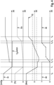
Figure 1 shows a method for changing over transmission stages of a transmission arrangement as the one disclosed in PTL1. Before the time t0 a signal requesting a changeover of an engaged transmission stage from a first transmission stage to a second transmission stage is reached. At the time t0 a setpoint value signal of the expulsion volume of the motor is set to zero. At the time t1 the expulsion volume equal to zero is reached. At this point in time the first transmission stage G1 is still engaged. - At the time t1, the zero expulsion volume of the motor can be detected (see Vg switch on the upper portion of
Figure 1 ) and the changing of the transmission stage can be started. It is to be noted that it is also possible that a time delay occurs between the arrival of the zero expulsion volume of the motor and the time at which the zero expulsion volume of the motor is effectively detected (as described inFigure 2 of PTL1). - At the time t2 the first transmission stage G1 is disengaged and at the time t3 the second transmission stage G2 is engaged. Thereafter, at the time t4, the expulsion volume of the motor is gradually increased in order to reach a desired amount.
- However, it is possible that, if particular conditions occur, the changing of the transmission stage cannot be completed, in particular in the interval between t2 and t3.
- For example due to a particular pressure or temperature, or velocity, it is possible that the drag torque of the motor reaches a value, which in the worst case hinders the safe engagement of the required gear.
- In particular, if the drag torque of the hydraulic motor and of the gearbox are out of the limits of the synchronizer, a safe engagement of a required gear cannot be completed successfully. This is because the synchronizer is capable to synchronize the speed but not able to engage with the second transmission stage G2. In the particular case depicted in
Figure 1 , if the drag torque exceeds a predetermined value, which is represented by the dashed horizontal line L1, the safe engagement of the required gear is hindered. - Furthermore,
DE 10 2011 055177 A1 - Scope of the present invention is, therefore, to provide a method for changing over transmission stages of a transmission arrangement, which enables to overcome the above mentioned problem.
- According to an embodiment of the present invention a method for changing over transmission stages of a transmission arrangement is provided, wherein the transmission arrangement comprises: a first hydraulic machine coupled to a drive machine, a second hydraulic machine having an adjustable expulsion volume, wherein the second hydraulic machine is fluidically connected to the first hydraulic machine via a first working line of the transmission arrangement and a second working line of the transmission arrangement, wherein the second hydraulic machine is coupled to a manual transmission of the transmission arrangement so that a torque can be transmitted, the manual transmission having at least two transmission stage. The method comprises the following steps:
- a) requesting a changeover of an engaged transmission stage from a first transmission stage to a second transmission stage;
- b) setting a setpoint value signal of the expulsion volume of the second hydraulic machine to zero;
- c) disengaging the first transmission stage, wherein before starting with said disengaging the first transmission stage the expulsion volume of the second hydraulic machine is already zero;
- d) regulating the second hydraulic machine so that expulsion volume of the second hydraulic machine reaches a value greater than zero so as to bring a drag torque of the second hydraulic machine (14) within a predetermined range;
- e) engaging the second transmission stage. In said method the steps a) to e) are executed sequentially.
- According to a further embodiment of the present invention a method is provided, wherein the expulsion volume of the second hydraulic machine is regulated by means of adjusting means, wherein during said step d) the expulsion volume of the second hydraulic machine is varied along a predetermined gradient between a first expulsion volume of the second hydraulic machine, which is equal to zero, and a second expulsion volume of the second hydraulic machine, which is greater than zero.
- According to a further embodiment of the present invention a method is provided, wherein said adjustment apparatus during said step d) receives an electrical actuation current, which gradually increases, wherein said electrical actuation current enables to proportionally adjust the expulsion volume of the second hydraulic machine.
- According to a further embodiment of the present invention a method is provided, wherein when the step c) is started the electrical actuation current is increased from zero to a predetermined value, wherein said predetermined value of the electrical actuation current causes the expulsion volume of the second hydraulic machine to remain equal to zero.
- According to a further embodiment of the present invention a method is provided, wherein the engaging of the second transmission stage of said step e) is executed by means of a synchronization unit which is configured to synchronize a rotation velocity of the second hydraulic machine with the velocity of the second transmission stage.
- The present invention is described with reference to the enclosed figures wherein the same reference numbers refer to the same parts and/or to similar parts and/or to corresponding parts of the system. In the figures:
-
Figure 1 shows a problem occurring by changing over transmission stages of a transmission arrangement according to the state of the art; -
Figure 2 shows a circuit diagram of a travel drive known by the state of the art; -
Figure 3 shows a time diagram of a change up of a transmission arrangement according to an embodiment of the present invention; -
Figure 4 shows a time diagram of a change down of a transmission arrangement according to an embodiment of the present invention. - In the following, the present invention is described with reference to particular embodiments as shown in the enclosed figures. Nevertheless, the present invention is not limited to the particular embodiments described in the following detailed description and shown in the figures, but rather the embodiments described simply exemplify several aspects of the present invention, the scope of which is defined by the claims.
- Further modifications and variations of the present invention will be clear for the person skilled in the art. The present description is thus to be considered as including all said modifications and/or variations of the present invention, the scope of which is defined by the claims.
- With reference to
figure 2 a travel drive known from the state of the art, and in particular from PTL1 will be described. Furthermore, with reference tofigures 3 and4 a method respectively for change up and change down of the travel drive offig. 2 according to an embodiment of the present invention will be described. - According to
fig. 2 , a travel drive 1, for example that of a mobile machine, has atransmission arrangement 3 with a drive machine 2 which is embodied as a diesel engine, ahydrostatic transmission 4 and a two-stage (in the exemplary embodiment) manual transmission 6. Thehydrostatic transmission 4 has a first hydraulic machine 8, which is configured as an axial piston pump with a swash plate design, which is fluidically connected, in a closed, hydraulic circuit, via twoworking lines hydraulic machine 14, embodied preferably as an axial piston motor with a swash plate design. - The first hydraulic machine 8 is coupled via a
motor shaft 16 to the drive machine 2. Adrive shaft 18 of the secondhydraulic machine 14 is coupled to aninput shaft 20 of the manual transmission 6. Anoutput shaft 22 of the manual transmission 6 is coupled to a differential 24 of a two-wheeled axle 26 of the travel drive 1. The twohydraulic machines 8, 14 each have an adjustable expulsion volume. The first hydraulic machine 8 is configured here in such a way that it can operate both as a hydraulic pump and as a hydraulic motor in all four quadrants, in both directions of torque. The secondhydraulic machine 14 has its adjustment range only between a zero expulsion volume and a positive maximum value. - Furthermore, the
transmission arrangement 3 has acontrol apparatus 28, in particular for controlling the torque of thedrive shaft 18 and of thetransmission input shaft 20, and the expulsion volumes of thehydraulic machines 8, 14. Ashifting request apparatus 30, a gearspeed selection apparatus 32, a direction oftravel selection apparatus 34, anaccelerator pedal 36, a creeping gearspeed selection apparatus 38, abrake pedal 40 and anautomatic selection apparatus 42 are connected in terms of signaling to thecontrol apparatus 28. All thespecified apparatuses 30 to 42 are connected in terms of signaling via a CAN bus 44, both to thecontrol apparatus 28 and at least to the drive machine 2. - The manual transmission 6 has a
lower transmission stage 46, and ahigher transmission stage 48 of the rotational speed nA of the output shaft 23 with respect to the rotational speed nHM of theinput shaft 18. Furthermore, the manual transmission 6 has asynchronization unit 50. Anactuator 52 of thesynchronization unit 50 is rigidly coupled to apiston 54 of anactuation cylinder 56, whose technical characteristics and functioning are explained in details in PTL1. - The
hydrostatic transmission 4 has a variable, continuously adjustable transmission ratio range. The manual transmission 6 which is connected downstream of the latter serves to cover a necessary speed range of the travel drive 1. Thetransmission arrangement 3 is configured here in such a way that the manual transmission 6 can be shifted during the travel operation. - The shifting or changing over of the transmission stages 46, 48 can be controlled in an automated fashion by means of the
control apparatus 28. For this purpose, thetransmission arrangement 3 has arotational speed sensor 76 by means of which the rotational speed nA of theoutput shaft 22 can be detected. In addition, it has a rotational speed sensor 78 for detecting the rotational speed of theinput shaft 18. Furthermore, the secondhydraulic machine 14 has aposition detection unit 92 which is configured as a proximity switch and by means of which the zero expulsion volume of the secondhydraulic machine 14 can be detected. - The
lower transmission stage 46 has agear wheel 80, which is fixedly coupled to theinput shaft 20 and is in permanent engagement with anidler wheel 82, which can be coupled to theoutput shaft 22 via thesynchronization unit 50. Correspondingly, thehigher transmission stage 48 has agear wheel 84, which is fixedly coupled to theinput shaft 20, and anidler wheel 86 which is permanently engaged therewith and can be coupled to theoutput shaft 22 by means of thesynchronization unit 50. - According to
fig. 2 , the first hydraulic machine 8 has anadjustment unit 88 for adjusting its expulsion volume and the secondhydraulic machine 14 has anadjustment apparatus 90 for adjusting its expulsion volume VH. Theadjustment apparatus 90 operates here electro-proportionally (EP adjustment). - In order to adjust a cradle of the second
hydraulic machine 14, and therefore the expulsion volume VH, theadjustment apparatus 90 has a hydraulic actuation cylinder, the pressure spaces of which, which are effective in a reciprocal fashion, can each be supplied with pressure medium via an electro-proportionally adjustable pressure regulating valve. The electro-proportional adjustment permits infinitely variable adjustment of the expulsion volume VH. In this context, the adjustment takes place proportionally with respect to an applied electrical actuation current IH. - A method respectively for change up and change down of the travel drive of
fig. 2 according to an embodiment of the present invention will be described in the following paragraphs. - Both in
figures 3 and4 are divided analogously from the top to the bottom into four sections. In the first section (from the top) an applied electrical actuation current (in mA) received by theadjustment apparatus 90 over the time is depicted. In the second section both a motor expulsion volume VH (with a dotted line) and a signal (Vg switch) are depicted, wherein the signal Vg switch indicates if the switching is allowed to take place (with a continuous line). The third section describes a trend of the manual transmission 6 input torque TQ over the time. Furthermore, the two horizontal lines describes an allowed torque range for the input torque TQ. The fourth and last section describes both a logic variable (gear engaged yes/no) for the lower and thehigher transmission stage 46, 48 (with continuous lines) and a displacement of the synchronization unit 50 (with a dashed line) over the time. - In the following, with reference to
figures 2 and3 , a method for change up will be described. - Before the time t0 a signal requesting a changeover of an engaged transmission stage from the
lower transmission stage 46 to thehigher transmission stage 48 is reached. - Starting from a point in time 0 (see
figure 3 ), at which thelower transmission stage 46 is engaged, theadjustment apparatus 90 of the secondhydraulic machine 14 is energized with a constant current IH, and the expulsion volume VH of the secondhydraulic machine 14 is at a predetermined value, and there is no shifting request present at all. - The request for shifting is made by means of the gear
speed selection apparatus 32 according tofig. 2 . As a result, thecontrol apparatus 28, at time t0, after receiving said request, lowers the actuation current IH of theadjustment apparatus 90 so that the cradle of the secondhydraulic machine 14 cause the expulsion volume of the secondhydraulic machine 14 to be equal to zero, by gradually changing the slope angle of the swash plate. - At the time t1 the expulsion volume equal to zero is reached. After a short dwell time, or simultaneously (as shown in the figure), the
position detection unit 92 detects this zero position of the cradle of the secondhydraulic machine 14 and outputs the corresponding signal to thecontrol apparatus 28. Therefore, the signal Vg switch, which indicates that the switching is allowed to take place, is set to a positive value and the switching is allowed to start. At this point in time thelower transmission stage 46 is still engaged. - At the same time t1 the
control apparatus 28 switches a 4/3-way switching valve 66 (seefigure 2 ) into it's a second switchedposition 66b. The secondpressure medium space 60 is then supplied with pressure medium from thepressure medium line 68. - In that way, the
synchronization unit 50, to be more precise the slidingsleeve 52 thereof, at time t2 is firstly actuated hydraulically by means of thecontrol apparatus 28. When thesynchronization unit 50 is actuated the electrical actuation current IH is increased from zero to a predetermined value, wherein said predetermined value of the electrical actuation current IH causes the expulsion volume VH of the secondhydraulic machine 14 to remain equal to zero. As an example said predetermined value can be equal to 360 mA. The value of the electrical actuation current IH is maintained constant until a time t3. The time interval between t2 and t3 can be equal to 130 ms. However, it is also possible to reduce said value to zero. - At time t3 the electrical actuation current IH is gradually increased from the first predetermined value. The electrical actuation current, as shown in the figure, can be increased with a constant gradient, for example 1.5 mA/10 ms if the interval between t2 and t3 is equal to 130 ms. After some time, when a threshold value is reached, the expulsion volume of the second hydraulic machine starts to increase and, therefore, the expulsion volume reaches a value greater than zero.
- Such a solution enables to reduce the high drag torque applied to the synchronous device during the shifting operation in such a way that the shifting operation can be carried out successfully. In this regard, as shown in
figure 3 , as soon as the expulsion volume VH of the secondhydraulic machine 14 starts to increase the drag torque TQ is reduced in such a way that its value is contained within a space between the two horizontal lines, which describes an allowed torque range for the input torque. By a change up the allowed range can be comprised between +25 Nm. Therefore, the procedure for reducing the drag torque TQ during the shifting process effectively reduces the drag torque and the shifting process can be accordingly implemented. - Thereafter the synchronization of the input shaft 20 (drive shaft 18) with the
output shaft 22 takes place. If the rotational speeds of theinput shaft 20 and of theoutput shaft 22 are synchronized according to the new transmission ratio of thehigher transmission stage 48 thesynchronization unit 50locks shaft 22 with thegear 86. As a result theoutput shaft 22 is connected in a rotationally fixed fashion to theidler wheel 86, and thehigher transmission stage 48 is engaged. This corresponds to the point in time t4. This result is achieved due to the above-described procedure for reducing the drag torque TQ during the shifting process, which effectively reduces the drag torque and enables the shifting process to be implemented. - With a certain delay, at the point in time t5, this rise is detected by the
position detection unit 92. Therefore, the signal Vg switch, which indicates that the switching is allowed to take place, is set to a negative value, which indicates that the switching has been completed. At this point in time t5 thehigher transmission stage 48 has been engaged. - At the point in time t5, the incremental raising of the actuation current IH of the
adjustment apparatus 90 takes place. Correspondingly, the expulsion volume VH of the secondhydraulic machine 14 follows and rises. The value of the reached expulsion volume VH is higher than the value of the expulsion volume VH at the point t0. The reason being that a change up occurred. In the same way the manual transmission 6 input torque TQ is higher than the value of the manual transmission 6 input torque TQ at the point t0. - In the following, with reference to
figures 2 and4 , a method for change down will be described. - Before the time t0 a signal requesting a changeover of an engaged transmission stage from the
higher transmission stage 48 to thelower transmission stage 46 is reached. - Starting from a point in time 0 (see
figure 4 ), at which thehigher transmission stage 48 is engaged, theadjustment apparatus 90 of the secondhydraulic machine 14 is energized with a constant current IH, and the expulsion volume VH of the secondhydraulic machine 14 is at a predetermined value, and there is no shifting request present at all. - The request for shifting is made by means of the gear
speed selection apparatus 32 according tofig. 2 . As a result, thecontrol apparatus 28, at time t0, after receiving said request, lowers the actuation current IH of theadjustment apparatus 90 so that the cradle of the secondhydraulic machine 14 cause the expulsion volume of the secondhydraulic machine 14 to be equal to zero, by gradually changing the slope angle of the swash plate. - At the time t1 the expulsion volume equal to zero is reached. After a short dwell time, or simultaneously (as shown in the figure), the
position detection unit 92 detects this zero position of the cradle of the secondhydraulic machine 14 and outputs the corresponding signal to thecontrol apparatus 28. Therefore, the signal Vg switch, which indicates that the switching is allowed to take place, is set to a positive value and the switching is allowed to start. At this point in time thelower transmission stage 46 is still engaged. - At the same time t1 the
control apparatus 28 switches a 4/3-way switching valve 66 (seefigure 2 ) into it's a first switchedposition 66a. The firstpressure medium space 60 is then supplied with pressure medium from thepressure medium line 68. - In that way, the
synchronization unit 50, to be more precise the slidingsleeve 52 thereof, at time t2 is firstly actuated hydraulically by means of thecontrol apparatus 28. When thesynchronization unit 50 is actuated the electrical actuation current IH is increased from zero to a predetermined value, wherein said predetermined value of the electrical actuation current IH causes the expulsion volume VH of the secondhydraulic machine 14 to remain equal to zero. As an example said predetermined value can be equal to 360 mA. The value of the electrical actuation current IH is maintained constant until a time t3. The time interval between t2 and t3 can be equal to 130 ms. However, it is also possible to reduce said value to zero. - At time t3 the electrical actuation current IH is gradually increased from the first predetermined value. The electrical actuation current, as shown in the figure, can be increased with a constant gradient, for example 1.5 mA/10 ms if the interval between t2 and t3 is equal to 130 ms or 1 mA/10 ms if the interval between t2 and t3 is equal to 0. After some time, when a threshold value is reached, the expulsion volume of the second hydraulic machine starts to increase and, therefore, the expulsion volume reaches a value greater than zero.
- Such a solution enables to reduce the high drag torque applied to the synchronous device during the shifting operation in such a way that the shifting operation can be carried out successfully. In this regard, as shown in
figure 4 , as soon as the expulsion volume VH of the secondhydraulic machine 14 starts to increase the drag torque is reduced in such a way that its value is contained within a space between the two horizontal lines, which describes an allowed torque range for the input torque. Therefore, the procedure for reducing the drag torque during the shifting process effectively reduces the drag torque and the shifting process can be accordingly implemented. By a change down the allowed range can be comprised between +13 Nm. - Thereafter the synchronization of the input shaft 20 (drive shaft 18) with the
output shaft 22 takes place. If the rotational speeds of theinput shaft 20 and of theoutput shaft 22 are synchronized according to the new transmission ratio of thelower transmission stage 46 thesynchronization unit 50locks shaft 22 with thegear 82. As a result theoutput shaft 22 is connected in a rotationally fixed fashion to theidler wheel 82, and thelower transmission stage 46 is engaged. This corresponds to the point in time t4. This result is achieved due to the above-described procedure for reducing the drag torque TQ during the shifting process, which effectively reduces the drag torque and enables the shifting process to be implemented. - With a certain delay, at the point in time t5, this rise is detected by the
position detection unit 92. Therefore, the signal Vg switch, which indicates that the switching is allowed to take place, is set to a negative value, which indicates that the switching has been completed. At this point in time t5 thelower transmission stage 48 has been engaged. - At the point in time t5, the incremental raising of the actuation current IH of the
adjustment apparatus 90 takes place. Correspondingly, the expulsion volume VH of the secondhydraulic machine 14 follows and rises. The value of the reached expulsion volume VH is lower than the value of the expulsion volume VH at the point t0. The reason being that a change down occurred. In the same way the manual transmission 6 input torque TQ is lower than the value of the manual transmission 6 input torque TQ at the point t0. - In addition, those areas in which it is believed that those of ordinary skill in the art are familiar, have not been described herein in order not to unnecessarily obscure the invention described.
- Accordingly, the invention is not to be limited by the specific illustrative embodiments, but only by the scope of the appended claims.
Claims (5)
- A method for changing over transmission stages (46, 48) of a transmission arrangement (3), the transmission arrangement (3) comprising:a first hydraulic machine (8) coupled to a drive machine (2),a second hydraulic machine (14) having an adjustable expulsion volume (VH), whereinthe second hydraulic machine (14) is fluidically connected to the first hydraulic machine (8) via a first working line (10) of the transmission arrangement (3) and a second working line (12) of the transmission arrangement (3), wherein the second hydraulic machine (14) is coupled to a manual transmission (6) of the transmission arrangement (3) so that a torque of the second hydraulic machine (14) can be transmitted to the manual transmission (6), the manual transmission (6) having at least two transmission stages (46, 48),the method comprising the following steps:a) requesting a changeover of an engaged transmission stage (46, 48) from a first transmission stage (46, 48) to a second transmission stage (46, 48);b) setting a setpoint value signal of the expulsion volume (VH) of the second hydraulic machine (14) to zero;c) disengaging the first transmission stage (46, 48), wherein before starting with said disengaging the first transmission stage (46, 48) the expulsion volume (VH) of the second hydraulic machine (14) is already zero;d) regulating the second hydraulic machine (14) so that expulsion volume (VH) of the second hydraulic machine (14) reaches a value greater than zero, so as to bring a drag torque of the second hydraulic machine (14) within a predetermined range;e) engaging the second transmission stage (46, 48);said steps a) to e) being executed sequentially.
- Method according to claim 1, wherein the expulsion volume (VH) of the second hydraulic machine (14) is regulated by means of adjusting means (90), , wherein during said step d) the expulsion volume (VH) of the second hydraulic machine (14) is varied along a predetermined gradient between a first expulsion volume (VH) of the second hydraulic machine (14), which is equal to zero, and a second expulsion volume (VH) of the second hydraulic machine (14), which is greater than zero.
- Method according to claim 2, wherein said adjustment apparatus (90) during said step d) receives an electrical actuation current (IH), which gradually increases, wherein said electrical actuation current (IH) enables to proportionally adjust the expulsion volume (VH) of the second hydraulic machine (14).
- Method according to claim 3, wherein when the step c) is started the electrical actuation current (IH) is set to a predetermined value, wherein said predetermined value of the electrical actuation current (IH) causes the expulsion volume (VH) of the second hydraulic machine (14) to remain equal to zero.
- Method according to any of any of claims 1 to 4, wherein the engaging of the second transmission stage (46, 48) of said step e) is executed by means of a synchronization unit (50) which is configured to synchronize a rotation velocity of the second hydraulic machine (14) with the velocity of the second transmission stage (46, 48).
Applications Claiming Priority (1)
| Application Number | Priority Date | Filing Date | Title |
|---|---|---|---|
| IT102020000006952A IT202000006952A1 (en) | 2020-04-02 | 2020-04-02 | METHOD FOR CHANGING THE TRANSMISSION STAGES OF A TRANSMISSION SYSTEM |
Publications (2)
| Publication Number | Publication Date |
|---|---|
| EP3889467A1 EP3889467A1 (en) | 2021-10-06 |
| EP3889467B1 true EP3889467B1 (en) | 2023-07-12 |
Family
ID=70918912
Family Applications (1)
| Application Number | Title | Priority Date | Filing Date |
|---|---|---|---|
| EP21165428.0A Active EP3889467B1 (en) | 2020-04-02 | 2021-03-29 | Method for changing over transmission stages of a transmission arrangement |
Country Status (2)
| Country | Link |
|---|---|
| EP (1) | EP3889467B1 (en) |
| IT (1) | IT202000006952A1 (en) |
Cited By (1)
| Publication number | Priority date | Publication date | Assignee | Title |
|---|---|---|---|---|
| EP4513063A1 (en) | 2023-08-25 | 2025-02-26 | Robert Bosch GmbH | Method for operating a mobile working machine, computing unit and mobile working machine |
Families Citing this family (1)
| Publication number | Priority date | Publication date | Assignee | Title |
|---|---|---|---|---|
| EP4425011B1 (en) | 2023-03-03 | 2026-05-06 | Robert Bosch GmbH | Method for changing over transmission stages of a transmission arrangement |
Family Cites Families (3)
| Publication number | Priority date | Publication date | Assignee | Title |
|---|---|---|---|---|
| DE4223846C2 (en) * | 1992-07-20 | 1996-03-28 | Hydromatik Gmbh | Gear unit for arrangement between a drive motor and a consumer |
| DE102011055177B4 (en) * | 2011-11-09 | 2021-03-04 | Linde Hydraulics Gmbh & Co. Kg | Hydrostatic drive for an all-wheel drive machine |
| DE102016215992A1 (en) | 2016-08-25 | 2018-03-01 | Robert Bosch Gmbh | Gear arrangement, traction drive with the gear assembly and method for controlling the gear assembly |
-
2020
- 2020-04-02 IT IT102020000006952A patent/IT202000006952A1/en unknown
-
2021
- 2021-03-29 EP EP21165428.0A patent/EP3889467B1/en active Active
Cited By (2)
| Publication number | Priority date | Publication date | Assignee | Title |
|---|---|---|---|---|
| EP4513063A1 (en) | 2023-08-25 | 2025-02-26 | Robert Bosch GmbH | Method for operating a mobile working machine, computing unit and mobile working machine |
| DE102023208168A1 (en) | 2023-08-25 | 2025-02-27 | Robert Bosch Gesellschaft mit beschränkter Haftung | Method for operating a mobile work machine, computing unit and mobile work machine |
Also Published As
| Publication number | Publication date |
|---|---|
| IT202000006952A1 (en) | 2021-10-02 |
| EP3889467A1 (en) | 2021-10-06 |
Similar Documents
| Publication | Publication Date | Title |
|---|---|---|
| US5553453A (en) | Method for providing different speed ranges for a speed pedal | |
| EP3889467A1 (en) | Method for changing over transmission stages of a transmission arrangement | |
| CN111615603B (en) | Electric transmission system and gear shifting method | |
| CN106564492A (en) | Method, device and TCU for controlling shifting rotation speed | |
| CN102144114B (en) | Method and transmission device for changing gear stages | |
| CN108528426A (en) | Control method and control device for hybrid electric vehicle | |
| CN117279813B (en) | Gear shift control method for hybrid power system and hybrid power system | |
| KR20170071479A (en) | Dual motor drive unit and method of drivingly engaging a first motor of dual motor drive unit with an output shaft | |
| US10907713B2 (en) | Transmission arrangement, travel drive having the transmission arrangement and method for controlling the transmission arrangement | |
| CN110171425A (en) | Hybrid vehicle AMT shift process power interruption compensating control method | |
| KR102059316B1 (en) | Method and apparatus for learning kiss point of transmission having dual clutch | |
| CN101445101B (en) | A method for controlling a downshift in an automatic transmission | |
| JP2007315507A (en) | Continuously variable transmission | |
| CN115217957B (en) | Control method for realizing automatic gear shifting of synchronizer and transmission controller | |
| GB9624947D0 (en) | Control device for an automatic motor-vehicle gearbox | |
| US20190032779A1 (en) | Hydraulic Machine Having an Adjustable Displacement Volume, Transmission Arrangement Having the Hydraulic Machine, and Method for Controlling the Transmission Arrangement | |
| US6394929B1 (en) | Shift control apparatus and shift control method of automatic transmission | |
| CN101617147A (en) | The method that is used for the automatic or semi-automatic transmission of operation heavy vehicle when the idling driving mode | |
| US5439424A (en) | CVT control system | |
| KR102002957B1 (en) | Method and apparatus for learning kiss point of transmission having dual clutch | |
| KR20010062837A (en) | Method for the coordinated controlling of an engine and a servo-clutch during reduction of torque during gearshift | |
| RU2650330C1 (en) | Method of gearbox control | |
| JP4200790B2 (en) | Clutch control device | |
| US6530291B1 (en) | Automatic shift-down apparatus for automatic transmission | |
| CN119428219A (en) | Method and device for controlling torque of a drive motor during gear shifting |
Legal Events
| Date | Code | Title | Description |
|---|---|---|---|
| PUAI | Public reference made under article 153(3) epc to a published international application that has entered the european phase |
Free format text: ORIGINAL CODE: 0009012 |
|
| STAA | Information on the status of an ep patent application or granted ep patent |
Free format text: STATUS: THE APPLICATION HAS BEEN PUBLISHED |
|
| AK | Designated contracting states |
Kind code of ref document: A1 Designated state(s): AL AT BE BG CH CY CZ DE DK EE ES FI FR GB GR HR HU IE IS IT LI LT LU LV MC MK MT NL NO PL PT RO RS SE SI SK SM TR |
|
| STAA | Information on the status of an ep patent application or granted ep patent |
Free format text: STATUS: REQUEST FOR EXAMINATION WAS MADE |
|
| 17P | Request for examination filed |
Effective date: 20220406 |
|
| RBV | Designated contracting states (corrected) |
Designated state(s): AL AT BE BG CH CY CZ DE DK EE ES FI FR GB GR HR HU IE IS IT LI LT LU LV MC MK MT NL NO PL PT RO RS SE SI SK SM TR |
|
| GRAP | Despatch of communication of intention to grant a patent |
Free format text: ORIGINAL CODE: EPIDOSNIGR1 |
|
| STAA | Information on the status of an ep patent application or granted ep patent |
Free format text: STATUS: GRANT OF PATENT IS INTENDED |
|
| RIC1 | Information provided on ipc code assigned before grant |
Ipc: F16H 59/68 20060101ALN20230215BHEP Ipc: F16H 61/70 20060101ALN20230215BHEP Ipc: F16H 61/04 20060101ALI20230215BHEP Ipc: F16H 61/02 20060101ALI20230215BHEP Ipc: F16H 61/682 20060101ALI20230215BHEP Ipc: F16H 61/42 20060101ALI20230215BHEP Ipc: F16H 47/02 20060101AFI20230215BHEP |
|
| INTG | Intention to grant announced |
Effective date: 20230321 |
|
| GRAS | Grant fee paid |
Free format text: ORIGINAL CODE: EPIDOSNIGR3 |
|
| GRAA | (expected) grant |
Free format text: ORIGINAL CODE: 0009210 |
|
| STAA | Information on the status of an ep patent application or granted ep patent |
Free format text: STATUS: THE PATENT HAS BEEN GRANTED |
|
| AK | Designated contracting states |
Kind code of ref document: B1 Designated state(s): AL AT BE BG CH CY CZ DE DK EE ES FI FR GB GR HR HU IE IS IT LI LT LU LV MC MK MT NL NO PL PT RO RS SE SI SK SM TR |
|
| REG | Reference to a national code |
Ref country code: CH Ref legal event code: EP |
|
| REG | Reference to a national code |
Ref country code: DE Ref legal event code: R096 Ref document number: 602021003354 Country of ref document: DE |
|
| REG | Reference to a national code |
Ref country code: IE Ref legal event code: FG4D |
|
| REG | Reference to a national code |
Ref country code: LT Ref legal event code: MG9D |
|
| REG | Reference to a national code |
Ref country code: NL Ref legal event code: MP Effective date: 20230712 |
|
| REG | Reference to a national code |
Ref country code: AT Ref legal event code: MK05 Ref document number: 1587500 Country of ref document: AT Kind code of ref document: T Effective date: 20230712 |
|
| PG25 | Lapsed in a contracting state [announced via postgrant information from national office to epo] |
Ref country code: NL Free format text: LAPSE BECAUSE OF FAILURE TO SUBMIT A TRANSLATION OF THE DESCRIPTION OR TO PAY THE FEE WITHIN THE PRESCRIBED TIME-LIMIT Effective date: 20230712 |
|
| PG25 | Lapsed in a contracting state [announced via postgrant information from national office to epo] |
Ref country code: GR Free format text: LAPSE BECAUSE OF FAILURE TO SUBMIT A TRANSLATION OF THE DESCRIPTION OR TO PAY THE FEE WITHIN THE PRESCRIBED TIME-LIMIT Effective date: 20231013 |
|
| PG25 | Lapsed in a contracting state [announced via postgrant information from national office to epo] |
Ref country code: ES Free format text: LAPSE BECAUSE OF FAILURE TO SUBMIT A TRANSLATION OF THE DESCRIPTION OR TO PAY THE FEE WITHIN THE PRESCRIBED TIME-LIMIT Effective date: 20230712 |
|
| PG25 | Lapsed in a contracting state [announced via postgrant information from national office to epo] |
Ref country code: IS Free format text: LAPSE BECAUSE OF FAILURE TO SUBMIT A TRANSLATION OF THE DESCRIPTION OR TO PAY THE FEE WITHIN THE PRESCRIBED TIME-LIMIT Effective date: 20231112 |
|
| PG25 | Lapsed in a contracting state [announced via postgrant information from national office to epo] |
Ref country code: SE Free format text: LAPSE BECAUSE OF FAILURE TO SUBMIT A TRANSLATION OF THE DESCRIPTION OR TO PAY THE FEE WITHIN THE PRESCRIBED TIME-LIMIT Effective date: 20230712 Ref country code: RS Free format text: LAPSE BECAUSE OF FAILURE TO SUBMIT A TRANSLATION OF THE DESCRIPTION OR TO PAY THE FEE WITHIN THE PRESCRIBED TIME-LIMIT Effective date: 20230712 Ref country code: PT Free format text: LAPSE BECAUSE OF FAILURE TO SUBMIT A TRANSLATION OF THE DESCRIPTION OR TO PAY THE FEE WITHIN THE PRESCRIBED TIME-LIMIT Effective date: 20231113 Ref country code: NO Free format text: LAPSE BECAUSE OF FAILURE TO SUBMIT A TRANSLATION OF THE DESCRIPTION OR TO PAY THE FEE WITHIN THE PRESCRIBED TIME-LIMIT Effective date: 20231012 Ref country code: LV Free format text: LAPSE BECAUSE OF FAILURE TO SUBMIT A TRANSLATION OF THE DESCRIPTION OR TO PAY THE FEE WITHIN THE PRESCRIBED TIME-LIMIT Effective date: 20230712 Ref country code: LT Free format text: LAPSE BECAUSE OF FAILURE TO SUBMIT A TRANSLATION OF THE DESCRIPTION OR TO PAY THE FEE WITHIN THE PRESCRIBED TIME-LIMIT Effective date: 20230712 Ref country code: IS Free format text: LAPSE BECAUSE OF FAILURE TO SUBMIT A TRANSLATION OF THE DESCRIPTION OR TO PAY THE FEE WITHIN THE PRESCRIBED TIME-LIMIT Effective date: 20231112 Ref country code: HR Free format text: LAPSE BECAUSE OF FAILURE TO SUBMIT A TRANSLATION OF THE DESCRIPTION OR TO PAY THE FEE WITHIN THE PRESCRIBED TIME-LIMIT Effective date: 20230712 Ref country code: GR Free format text: LAPSE BECAUSE OF FAILURE TO SUBMIT A TRANSLATION OF THE DESCRIPTION OR TO PAY THE FEE WITHIN THE PRESCRIBED TIME-LIMIT Effective date: 20231013 Ref country code: FI Free format text: LAPSE BECAUSE OF FAILURE TO SUBMIT A TRANSLATION OF THE DESCRIPTION OR TO PAY THE FEE WITHIN THE PRESCRIBED TIME-LIMIT Effective date: 20230712 Ref country code: ES Free format text: LAPSE BECAUSE OF FAILURE TO SUBMIT A TRANSLATION OF THE DESCRIPTION OR TO PAY THE FEE WITHIN THE PRESCRIBED TIME-LIMIT Effective date: 20230712 Ref country code: AT Free format text: LAPSE BECAUSE OF FAILURE TO SUBMIT A TRANSLATION OF THE DESCRIPTION OR TO PAY THE FEE WITHIN THE PRESCRIBED TIME-LIMIT Effective date: 20230712 |
|
| PG25 | Lapsed in a contracting state [announced via postgrant information from national office to epo] |
Ref country code: PL Free format text: LAPSE BECAUSE OF FAILURE TO SUBMIT A TRANSLATION OF THE DESCRIPTION OR TO PAY THE FEE WITHIN THE PRESCRIBED TIME-LIMIT Effective date: 20230712 |
|
| REG | Reference to a national code |
Ref country code: DE Ref legal event code: R097 Ref document number: 602021003354 Country of ref document: DE |
|
| PG25 | Lapsed in a contracting state [announced via postgrant information from national office to epo] |
Ref country code: SM Free format text: LAPSE BECAUSE OF FAILURE TO SUBMIT A TRANSLATION OF THE DESCRIPTION OR TO PAY THE FEE WITHIN THE PRESCRIBED TIME-LIMIT Effective date: 20230712 Ref country code: RO Free format text: LAPSE BECAUSE OF FAILURE TO SUBMIT A TRANSLATION OF THE DESCRIPTION OR TO PAY THE FEE WITHIN THE PRESCRIBED TIME-LIMIT Effective date: 20230712 Ref country code: EE Free format text: LAPSE BECAUSE OF FAILURE TO SUBMIT A TRANSLATION OF THE DESCRIPTION OR TO PAY THE FEE WITHIN THE PRESCRIBED TIME-LIMIT Effective date: 20230712 Ref country code: DK Free format text: LAPSE BECAUSE OF FAILURE TO SUBMIT A TRANSLATION OF THE DESCRIPTION OR TO PAY THE FEE WITHIN THE PRESCRIBED TIME-LIMIT Effective date: 20230712 Ref country code: CZ Free format text: LAPSE BECAUSE OF FAILURE TO SUBMIT A TRANSLATION OF THE DESCRIPTION OR TO PAY THE FEE WITHIN THE PRESCRIBED TIME-LIMIT Effective date: 20230712 Ref country code: SK Free format text: LAPSE BECAUSE OF FAILURE TO SUBMIT A TRANSLATION OF THE DESCRIPTION OR TO PAY THE FEE WITHIN THE PRESCRIBED TIME-LIMIT Effective date: 20230712 |
|
| PLBE | No opposition filed within time limit |
Free format text: ORIGINAL CODE: 0009261 |
|
| STAA | Information on the status of an ep patent application or granted ep patent |
Free format text: STATUS: NO OPPOSITION FILED WITHIN TIME LIMIT |
|
| 26N | No opposition filed |
Effective date: 20240415 |
|
| PG25 | Lapsed in a contracting state [announced via postgrant information from national office to epo] |
Ref country code: SI Free format text: LAPSE BECAUSE OF FAILURE TO SUBMIT A TRANSLATION OF THE DESCRIPTION OR TO PAY THE FEE WITHIN THE PRESCRIBED TIME-LIMIT Effective date: 20230712 |
|
| REG | Reference to a national code |
Ref country code: CH Ref legal event code: PL |
|
| PG25 | Lapsed in a contracting state [announced via postgrant information from national office to epo] |
Ref country code: BG Free format text: LAPSE BECAUSE OF FAILURE TO SUBMIT A TRANSLATION OF THE DESCRIPTION OR TO PAY THE FEE WITHIN THE PRESCRIBED TIME-LIMIT Effective date: 20230712 |
|
| PG25 | Lapsed in a contracting state [announced via postgrant information from national office to epo] |
Ref country code: LU Free format text: LAPSE BECAUSE OF NON-PAYMENT OF DUE FEES Effective date: 20240329 |
|
| PG25 | Lapsed in a contracting state [announced via postgrant information from national office to epo] |
Ref country code: MC Free format text: LAPSE BECAUSE OF FAILURE TO SUBMIT A TRANSLATION OF THE DESCRIPTION OR TO PAY THE FEE WITHIN THE PRESCRIBED TIME-LIMIT Effective date: 20230712 |
|
| PG25 | Lapsed in a contracting state [announced via postgrant information from national office to epo] |
Ref country code: MC Free format text: LAPSE BECAUSE OF FAILURE TO SUBMIT A TRANSLATION OF THE DESCRIPTION OR TO PAY THE FEE WITHIN THE PRESCRIBED TIME-LIMIT Effective date: 20230712 Ref country code: LU Free format text: LAPSE BECAUSE OF NON-PAYMENT OF DUE FEES Effective date: 20240329 Ref country code: BG Free format text: LAPSE BECAUSE OF FAILURE TO SUBMIT A TRANSLATION OF THE DESCRIPTION OR TO PAY THE FEE WITHIN THE PRESCRIBED TIME-LIMIT Effective date: 20230712 |
|
| REG | Reference to a national code |
Ref country code: BE Ref legal event code: MM Effective date: 20240331 |
|
| PG25 | Lapsed in a contracting state [announced via postgrant information from national office to epo] |
Ref country code: BE Free format text: LAPSE BECAUSE OF NON-PAYMENT OF DUE FEES Effective date: 20240331 |
|
| PG25 | Lapsed in a contracting state [announced via postgrant information from national office to epo] |
Ref country code: FR Free format text: LAPSE BECAUSE OF NON-PAYMENT OF DUE FEES Effective date: 20240331 |
|
| PG25 | Lapsed in a contracting state [announced via postgrant information from national office to epo] |
Ref country code: IE Free format text: LAPSE BECAUSE OF NON-PAYMENT OF DUE FEES Effective date: 20240329 |
|
| PG25 | Lapsed in a contracting state [announced via postgrant information from national office to epo] |
Ref country code: FR Free format text: LAPSE BECAUSE OF NON-PAYMENT OF DUE FEES Effective date: 20240331 Ref country code: BE Free format text: LAPSE BECAUSE OF NON-PAYMENT OF DUE FEES Effective date: 20240331 Ref country code: IE Free format text: LAPSE BECAUSE OF NON-PAYMENT OF DUE FEES Effective date: 20240329 Ref country code: CH Free format text: LAPSE BECAUSE OF NON-PAYMENT OF DUE FEES Effective date: 20240331 |
|
| PGFP | Annual fee paid to national office [announced via postgrant information from national office to epo] |
Ref country code: DE Payment date: 20250522 Year of fee payment: 5 |
|
| PGFP | Annual fee paid to national office [announced via postgrant information from national office to epo] |
Ref country code: IT Payment date: 20250331 Year of fee payment: 5 |
|
| PG25 | Lapsed in a contracting state [announced via postgrant information from national office to epo] |
Ref country code: CY Free format text: LAPSE BECAUSE OF FAILURE TO SUBMIT A TRANSLATION OF THE DESCRIPTION OR TO PAY THE FEE WITHIN THE PRESCRIBED TIME-LIMIT; INVALID AB INITIO Effective date: 20210329 |
|
| PG25 | Lapsed in a contracting state [announced via postgrant information from national office to epo] |
Ref country code: HU Free format text: LAPSE BECAUSE OF FAILURE TO SUBMIT A TRANSLATION OF THE DESCRIPTION OR TO PAY THE FEE WITHIN THE PRESCRIBED TIME-LIMIT; INVALID AB INITIO Effective date: 20210329 |
|
| GBPC | Gb: european patent ceased through non-payment of renewal fee |
Effective date: 20250329 |
|
| PG25 | Lapsed in a contracting state [announced via postgrant information from national office to epo] |
Ref country code: TR Free format text: LAPSE BECAUSE OF FAILURE TO SUBMIT A TRANSLATION OF THE DESCRIPTION OR TO PAY THE FEE WITHIN THE PRESCRIBED TIME-LIMIT Effective date: 20230712 |
|
| PG25 | Lapsed in a contracting state [announced via postgrant information from national office to epo] |
Ref country code: GB Free format text: LAPSE BECAUSE OF NON-PAYMENT OF DUE FEES Effective date: 20250329 |