EP3889454A1 - Sealing device - Google Patents
Sealing device Download PDFInfo
- Publication number
- EP3889454A1 EP3889454A1 EP19890437.7A EP19890437A EP3889454A1 EP 3889454 A1 EP3889454 A1 EP 3889454A1 EP 19890437 A EP19890437 A EP 19890437A EP 3889454 A1 EP3889454 A1 EP 3889454A1
- Authority
- EP
- European Patent Office
- Prior art keywords
- peripheral surface
- lip
- seal lip
- inner peripheral
- bumps
- Prior art date
- Legal status (The legal status is an assumption and is not a legal conclusion. Google has not performed a legal analysis and makes no representation as to the accuracy of the status listed.)
- Granted
Links
Images




Classifications
-
- F—MECHANICAL ENGINEERING; LIGHTING; HEATING; WEAPONS; BLASTING
- F16—ENGINEERING ELEMENTS AND UNITS; GENERAL MEASURES FOR PRODUCING AND MAINTAINING EFFECTIVE FUNCTIONING OF MACHINES OR INSTALLATIONS; THERMAL INSULATION IN GENERAL
- F16J—PISTONS; CYLINDERS; SEALINGS
- F16J15/00—Sealings
- F16J15/16—Sealings between relatively-moving surfaces
- F16J15/32—Sealings between relatively-moving surfaces with elastic sealings, e.g. O-rings
- F16J15/3244—Sealings between relatively-moving surfaces with elastic sealings, e.g. O-rings with hydrodynamic pumping action
-
- B—PERFORMING OPERATIONS; TRANSPORTING
- B61—RAILWAYS
- B61F—RAIL VEHICLE SUSPENSIONS, e.g. UNDERFRAMES, BOGIES OR ARRANGEMENTS OF WHEEL AXLES; RAIL VEHICLES FOR USE ON TRACKS OF DIFFERENT WIDTH; PREVENTING DERAILING OF RAIL VEHICLES; WHEEL GUARDS, OBSTRUCTION REMOVERS OR THE LIKE FOR RAIL VEHICLES
- B61F15/00—Axle-boxes
- B61F15/20—Details
- B61F15/22—Sealing means preventing entrance of dust or leakage of oil
-
- F—MECHANICAL ENGINEERING; LIGHTING; HEATING; WEAPONS; BLASTING
- F16—ENGINEERING ELEMENTS AND UNITS; GENERAL MEASURES FOR PRODUCING AND MAINTAINING EFFECTIVE FUNCTIONING OF MACHINES OR INSTALLATIONS; THERMAL INSULATION IN GENERAL
- F16C—SHAFTS; FLEXIBLE SHAFTS; ELEMENTS OR CRANKSHAFT MECHANISMS; ROTARY BODIES OTHER THAN GEARING ELEMENTS; BEARINGS
- F16C19/00—Bearings with rolling contact, for exclusively rotary movement
- F16C19/22—Bearings with rolling contact, for exclusively rotary movement with bearing rollers essentially of the same size in one or more circular rows, e.g. needle bearings
-
- F—MECHANICAL ENGINEERING; LIGHTING; HEATING; WEAPONS; BLASTING
- F16—ENGINEERING ELEMENTS AND UNITS; GENERAL MEASURES FOR PRODUCING AND MAINTAINING EFFECTIVE FUNCTIONING OF MACHINES OR INSTALLATIONS; THERMAL INSULATION IN GENERAL
- F16C—SHAFTS; FLEXIBLE SHAFTS; ELEMENTS OR CRANKSHAFT MECHANISMS; ROTARY BODIES OTHER THAN GEARING ELEMENTS; BEARINGS
- F16C19/00—Bearings with rolling contact, for exclusively rotary movement
- F16C19/22—Bearings with rolling contact, for exclusively rotary movement with bearing rollers essentially of the same size in one or more circular rows, e.g. needle bearings
- F16C19/34—Bearings with rolling contact, for exclusively rotary movement with bearing rollers essentially of the same size in one or more circular rows, e.g. needle bearings for both radial and axial load
-
- F—MECHANICAL ENGINEERING; LIGHTING; HEATING; WEAPONS; BLASTING
- F16—ENGINEERING ELEMENTS AND UNITS; GENERAL MEASURES FOR PRODUCING AND MAINTAINING EFFECTIVE FUNCTIONING OF MACHINES OR INSTALLATIONS; THERMAL INSULATION IN GENERAL
- F16C—SHAFTS; FLEXIBLE SHAFTS; ELEMENTS OR CRANKSHAFT MECHANISMS; ROTARY BODIES OTHER THAN GEARING ELEMENTS; BEARINGS
- F16C33/00—Parts of bearings; Special methods for making bearings or parts thereof
- F16C33/72—Sealings
- F16C33/76—Sealings of ball or roller bearings
- F16C33/78—Sealings of ball or roller bearings with a diaphragm, disc, or ring, with or without resilient members
- F16C33/7803—Sealings of ball or roller bearings with a diaphragm, disc, or ring, with or without resilient members suited for particular types of rolling bearings
- F16C33/7806—Sealings of ball or roller bearings with a diaphragm, disc, or ring, with or without resilient members suited for particular types of rolling bearings for spherical roller bearings
-
- F—MECHANICAL ENGINEERING; LIGHTING; HEATING; WEAPONS; BLASTING
- F16—ENGINEERING ELEMENTS AND UNITS; GENERAL MEASURES FOR PRODUCING AND MAINTAINING EFFECTIVE FUNCTIONING OF MACHINES OR INSTALLATIONS; THERMAL INSULATION IN GENERAL
- F16C—SHAFTS; FLEXIBLE SHAFTS; ELEMENTS OR CRANKSHAFT MECHANISMS; ROTARY BODIES OTHER THAN GEARING ELEMENTS; BEARINGS
- F16C33/00—Parts of bearings; Special methods for making bearings or parts thereof
- F16C33/72—Sealings
- F16C33/76—Sealings of ball or roller bearings
- F16C33/78—Sealings of ball or roller bearings with a diaphragm, disc, or ring, with or without resilient members
- F16C33/7816—Details of the sealing or parts thereof, e.g. geometry, material
- F16C33/782—Details of the sealing or parts thereof, e.g. geometry, material of the sealing region
- F16C33/7823—Details of the sealing or parts thereof, e.g. geometry, material of the sealing region of sealing lips
-
- F—MECHANICAL ENGINEERING; LIGHTING; HEATING; WEAPONS; BLASTING
- F16—ENGINEERING ELEMENTS AND UNITS; GENERAL MEASURES FOR PRODUCING AND MAINTAINING EFFECTIVE FUNCTIONING OF MACHINES OR INSTALLATIONS; THERMAL INSULATION IN GENERAL
- F16C—SHAFTS; FLEXIBLE SHAFTS; ELEMENTS OR CRANKSHAFT MECHANISMS; ROTARY BODIES OTHER THAN GEARING ELEMENTS; BEARINGS
- F16C33/00—Parts of bearings; Special methods for making bearings or parts thereof
- F16C33/72—Sealings
- F16C33/76—Sealings of ball or roller bearings
- F16C33/78—Sealings of ball or roller bearings with a diaphragm, disc, or ring, with or without resilient members
- F16C33/784—Sealings of ball or roller bearings with a diaphragm, disc, or ring, with or without resilient members mounted to a groove in the inner surface of the outer race and extending toward the inner race
- F16C33/7843—Sealings of ball or roller bearings with a diaphragm, disc, or ring, with or without resilient members mounted to a groove in the inner surface of the outer race and extending toward the inner race with a single annular sealing disc
- F16C33/7853—Sealings of ball or roller bearings with a diaphragm, disc, or ring, with or without resilient members mounted to a groove in the inner surface of the outer race and extending toward the inner race with a single annular sealing disc with one or more sealing lips to contact the inner race
-
- F—MECHANICAL ENGINEERING; LIGHTING; HEATING; WEAPONS; BLASTING
- F16—ENGINEERING ELEMENTS AND UNITS; GENERAL MEASURES FOR PRODUCING AND MAINTAINING EFFECTIVE FUNCTIONING OF MACHINES OR INSTALLATIONS; THERMAL INSULATION IN GENERAL
- F16C—SHAFTS; FLEXIBLE SHAFTS; ELEMENTS OR CRANKSHAFT MECHANISMS; ROTARY BODIES OTHER THAN GEARING ELEMENTS; BEARINGS
- F16C33/00—Parts of bearings; Special methods for making bearings or parts thereof
- F16C33/72—Sealings
- F16C33/76—Sealings of ball or roller bearings
- F16C33/78—Sealings of ball or roller bearings with a diaphragm, disc, or ring, with or without resilient members
- F16C33/784—Sealings of ball or roller bearings with a diaphragm, disc, or ring, with or without resilient members mounted to a groove in the inner surface of the outer race and extending toward the inner race
- F16C33/7843—Sealings of ball or roller bearings with a diaphragm, disc, or ring, with or without resilient members mounted to a groove in the inner surface of the outer race and extending toward the inner race with a single annular sealing disc
- F16C33/7853—Sealings of ball or roller bearings with a diaphragm, disc, or ring, with or without resilient members mounted to a groove in the inner surface of the outer race and extending toward the inner race with a single annular sealing disc with one or more sealing lips to contact the inner race
- F16C33/7856—Sealings of ball or roller bearings with a diaphragm, disc, or ring, with or without resilient members mounted to a groove in the inner surface of the outer race and extending toward the inner race with a single annular sealing disc with one or more sealing lips to contact the inner race with a single sealing lip
-
- F—MECHANICAL ENGINEERING; LIGHTING; HEATING; WEAPONS; BLASTING
- F16—ENGINEERING ELEMENTS AND UNITS; GENERAL MEASURES FOR PRODUCING AND MAINTAINING EFFECTIVE FUNCTIONING OF MACHINES OR INSTALLATIONS; THERMAL INSULATION IN GENERAL
- F16C—SHAFTS; FLEXIBLE SHAFTS; ELEMENTS OR CRANKSHAFT MECHANISMS; ROTARY BODIES OTHER THAN GEARING ELEMENTS; BEARINGS
- F16C33/00—Parts of bearings; Special methods for making bearings or parts thereof
- F16C33/72—Sealings
- F16C33/76—Sealings of ball or roller bearings
- F16C33/78—Sealings of ball or roller bearings with a diaphragm, disc, or ring, with or without resilient members
- F16C33/7869—Sealings of ball or roller bearings with a diaphragm, disc, or ring, with or without resilient members mounted with a cylindrical portion to the inner surface of the outer race and having a radial portion extending inward
- F16C33/7873—Sealings of ball or roller bearings with a diaphragm, disc, or ring, with or without resilient members mounted with a cylindrical portion to the inner surface of the outer race and having a radial portion extending inward with a single sealing ring of generally L-shaped cross-section
- F16C33/7876—Sealings of ball or roller bearings with a diaphragm, disc, or ring, with or without resilient members mounted with a cylindrical portion to the inner surface of the outer race and having a radial portion extending inward with a single sealing ring of generally L-shaped cross-section with sealing lips
-
- F—MECHANICAL ENGINEERING; LIGHTING; HEATING; WEAPONS; BLASTING
- F16—ENGINEERING ELEMENTS AND UNITS; GENERAL MEASURES FOR PRODUCING AND MAINTAINING EFFECTIVE FUNCTIONING OF MACHINES OR INSTALLATIONS; THERMAL INSULATION IN GENERAL
- F16C—SHAFTS; FLEXIBLE SHAFTS; ELEMENTS OR CRANKSHAFT MECHANISMS; ROTARY BODIES OTHER THAN GEARING ELEMENTS; BEARINGS
- F16C33/00—Parts of bearings; Special methods for making bearings or parts thereof
- F16C33/72—Sealings
- F16C33/76—Sealings of ball or roller bearings
- F16C33/78—Sealings of ball or roller bearings with a diaphragm, disc, or ring, with or without resilient members
- F16C33/7869—Sealings of ball or roller bearings with a diaphragm, disc, or ring, with or without resilient members mounted with a cylindrical portion to the inner surface of the outer race and having a radial portion extending inward
- F16C33/7879—Sealings of ball or roller bearings with a diaphragm, disc, or ring, with or without resilient members mounted with a cylindrical portion to the inner surface of the outer race and having a radial portion extending inward with a further sealing ring
- F16C33/7883—Sealings of ball or roller bearings with a diaphragm, disc, or ring, with or without resilient members mounted with a cylindrical portion to the inner surface of the outer race and having a radial portion extending inward with a further sealing ring mounted to the inner race and of generally L-shape, the two sealing rings defining a sealing with box-shaped cross-section
-
- F—MECHANICAL ENGINEERING; LIGHTING; HEATING; WEAPONS; BLASTING
- F16—ENGINEERING ELEMENTS AND UNITS; GENERAL MEASURES FOR PRODUCING AND MAINTAINING EFFECTIVE FUNCTIONING OF MACHINES OR INSTALLATIONS; THERMAL INSULATION IN GENERAL
- F16J—PISTONS; CYLINDERS; SEALINGS
- F16J15/00—Sealings
- F16J15/16—Sealings between relatively-moving surfaces
- F16J15/32—Sealings between relatively-moving surfaces with elastic sealings, e.g. O-rings
- F16J15/3204—Sealings between relatively-moving surfaces with elastic sealings, e.g. O-rings with at least one lip
- F16J15/3232—Sealings between relatively-moving surfaces with elastic sealings, e.g. O-rings with at least one lip having two or more lips
-
- F—MECHANICAL ENGINEERING; LIGHTING; HEATING; WEAPONS; BLASTING
- F16—ENGINEERING ELEMENTS AND UNITS; GENERAL MEASURES FOR PRODUCING AND MAINTAINING EFFECTIVE FUNCTIONING OF MACHINES OR INSTALLATIONS; THERMAL INSULATION IN GENERAL
- F16J—PISTONS; CYLINDERS; SEALINGS
- F16J15/00—Sealings
- F16J15/16—Sealings between relatively-moving surfaces
- F16J15/32—Sealings between relatively-moving surfaces with elastic sealings, e.g. O-rings
- F16J15/324—Arrangements for lubrication or cooling of the sealing itself
-
- F—MECHANICAL ENGINEERING; LIGHTING; HEATING; WEAPONS; BLASTING
- F16—ENGINEERING ELEMENTS AND UNITS; GENERAL MEASURES FOR PRODUCING AND MAINTAINING EFFECTIVE FUNCTIONING OF MACHINES OR INSTALLATIONS; THERMAL INSULATION IN GENERAL
- F16J—PISTONS; CYLINDERS; SEALINGS
- F16J15/00—Sealings
- F16J15/16—Sealings between relatively-moving surfaces
- F16J15/32—Sealings between relatively-moving surfaces with elastic sealings, e.g. O-rings
- F16J15/3248—Sealings between relatively-moving surfaces with elastic sealings, e.g. O-rings provided with casings or supports
- F16J15/3252—Sealings between relatively-moving surfaces with elastic sealings, e.g. O-rings provided with casings or supports with rigid casings or supports
- F16J15/3256—Sealings between relatively-moving surfaces with elastic sealings, e.g. O-rings provided with casings or supports with rigid casings or supports comprising two casing or support elements, one attached to each surface, e.g. cartridge or cassette seals
Definitions
- the present invention relates to sealing devices for interior sealing of rolling bearings.
- Patent Document 1 discloses a rolling bearing suitable for use in railroad vehicles.
- the interior of the rolling bearing is subject to temperature variations due to heat generated by friction between rolling elements and surrounding elements, resulting in changes in pressure inside the rolling bearing.
- the rolling bearing is provided with sealing devices for sealing lubricant therein, and the sealing devices are in slidable contact with the rotating inner race. Upon a change in pressure inside the bearing, a strong force acts on the sealing devices in contact with the inner race, and heat is generated by friction.
- the bearing disclosed in Patent Document 1 is provided with a plug for venting air.
- Patent Document 1 Japanese Utility Model Publication 4-123871
- Another approach for minimizing heat generation in a bearing is conceived in which a countermeasure for reducing heat generation is applied to a sealing device within the bearing, rather than to the bearing. In this case, it is desirable to ensure that the ability of the sealing device to seal a lubricant (grease) within the bearing, which is the original function of the device, is not compromised.
- the present invention provides a sealing device that has a superior ability to seal a lubricant and that is capable of reducing a likelihood of heat generation due to an increase in friction even when an internal pressure in a bearing rises or falls.
- a sealing device is disposed between an inner member and an outer member of a rolling bearing, which rotate relative to each other, for sealing a gap between the inner member and the outer member.
- the sealing device includes an annular rigid part that is to be fixed to an inside of a hole of the outer member, the rigid part being made from a rigid material; and an elastic part fixed to the rigid part, the elastic part being made from an elastic material.
- the elastic part includes a seal lip shaped as a truncated cone ring that is to be in slidable contact with the inner member or a member fixed to the inner member. Multiple bumps are formed on an inner peripheral surface of the seal lip. The bumps are always in slidable contact with the inner member or the member fixed to the inner member, and clearances are provided between the seal lip and the inner member or the member fixed to the inner member in vicinities of the bumps.
- the seal lip which is in slidable contact with the inner member or a member fixed to the inner member, seals the lubricant inside the bearing, resulting in a superior ability to seal the lubricant.
- multiple bumps formed on the inner peripheral surface of the seal lip are always in slidable contact with the inner member or the member fixed to the inner member, and small clearances exist between the seal lip and the inner member or the member fixed to the inner member in vicinities of the bumps.
- Fig. 1 shows a bearing for an axle of a railroad vehicle, which is an example of a rolling bearing 2 in which a sealing device 1 according to a first embodiment of the present invention is used.
- the present invention is not limited to bearings for railroad vehicles, and is applicable to axle bearings of large automotive vehicles such as trucks and buses.
- the illustrated rolling bearing 2 is an RCT (Rotating End Cap Tapered Roller) bearing.
- RCT Rotary End Cap Tapered Roller
- use of the present invention is not limited to RCT bearings, and the present invention is also applicable to other rolling bearings having other types of rolling elements, such as RCC (Rotating End Cap) bearings, ball bearings, and needle bearings.
- the rolling bearing 2 includes an inner race (inner member) 6 into which an axle 4 is inserted, an outer race (outer member) 8 arranged outside the inner race 6, multiple rollers 10 aligned in a row between the inner race 6 and the outer race 8, an oil stopping member (inner member) 12 into which the axle 4 is to be inserted, and a retainer 14 that retains the row of the rollers 10 in a fixed position.
- the outer race 8 is stationary, the inner race 6 and the oil stopping member 12 rotate with rotation of the axle 4.
- the retainer 14 is fixed to the outer race 8.
- the oil stopping member 12 includes a cylindrical part 12A with an outer diameter and an inner diameter that are the same as those of the inner race 6, a flange 12B extending from the end on the atmosphere side A of the cylindrical part 12A, and an outer cylindrical part 12C extending from the outer edge of the flange 12B toward the bearing inner side B.
- the cylindrical part 12A, the flange 12B, and the outer cylindrical part 12C define a circumferential groove 12D.
- the oil stopping member 12 is depicted by phantom lines.
- the sealing device 1 is located between the oil stopping member 12 and the outer race 8, which rotate relative to each other, and acts to seal the gap between the oil stopping member 12 and the outer race 8.
- the sealing device 1 acts to prevent or reduce outflow of grease, i.e., lubricant, from the inside of the rolling bearing 2, and to prevent or reduce ingress of foreign matter (water, including muddy water and salt water) and/or dust (including iron dust)) from the outside to the inside of the rolling bearing 2.
- arrow D indicates an example of the flow direction of foreign matter from the outside.
- Fig. 1 only the left side with respect to the axle 4 is shown, but the rotational shapes of sealing device 1 and the rolling bearing 2 are symmetric.
- the upper side of Fig. 1 is the bearing inner side B, and the lower side is the atmosphere side A.
- another sealing device similar to the sealing device 1 is provided on the opposite side of the rolling bearing 2 from the sealing device 1.
- the sealing device 1 includes three annular sealing members, i.e., an outer sealing member 16, an intermediate sealing member 18, and an inner sealing member 20.
- the outer sealing member 16 is made from a rigid material such as a metal.
- the outer sealing member 16 includes an outer cylindrical section 16A that is to be fixedly engaged in the hole 8A of the outer race 8, a circular annular section 16B, an intermediate cylindrical section 16C, a circular annular section 16D, and an inner cylindrical section 16E.
- the cylindrical sections 16A, 16C, and 16E are cylinders that are coaxial to one another.
- the outer cylindrical section 16A is fixedly engaged in the inner peripheral surface of the hole 8A of the outer race 8 by interference fit.
- the end portion 16Aa on the bearing inner side B of the outer cylindrical section 16A is hook-shaped and extends radially outward.
- a ridge 8B extending in a circumferential direction is formed in the hole 8A, and a circumferential groove into which the ridge 8B is fitted is formed in the end portion 16Aa of the outer cylindrical section 16A.
- the circular annular section 16B extends radially inward from the end on the atmosphere side A of the outer cylindrical section 16A.
- the circular annular section 16B lies on a plane that is perpendicular to the axial direction of the axle 4.
- the intermediate cylindrical section 16C extends from the inner edge of the circular annular section 16B toward the atmosphere side A.
- the circular annular section 16D extends radially inward from the end on the atmosphere side A of the intermediate cylindrical section 16C.
- the circular annular section 16D lies on a plane that is perpendicular to the axial direction of the axle 4.
- the inner cylindrical section 16E extends from the inner edge of the circular annular section 16D toward the atmosphere side A.
- An annular clearance is provided between the inner peripheral surface of the inner cylindrical section 16E and the outer peripheral surface of the outer cylindrical part 12C of the oil stopping member 12.
- the intermediate sealing member 18 is formed from a rigid material, for example, a metal.
- the intermediate sealing member 18 includes an outer cylindrical section 18A that is to be fixed to the outer sealing member 16, a circular annular section 18B, and an inner cylindrical section 18C.
- the outer cylindrical sections 18A and 18C are cylinders that are coaxial to each other.
- the outer cylindrical section 18A is engaged by interference fit with the inner peripheral surface of the intermediate cylindrical section 16C of the outer sealing member 16.
- the circular annular section 18B extends radially inward from the end on the bearing inner side B of the outer cylindrical section 18A.
- the circular annular section 18B generally lies on a plane that is perpendicular to the axial direction of the axle 4, but is curved.
- the inner cylindrical section 18C extends from the inner edge of the circular annular section 18B toward the bearing inner side B.
- An annular clearance is provided between the inner peripheral surface of the inner cylindrical section 18c and the outer peripheral surface of the cylindrical part 12A of the oil stopping member 12.
- the inner sealing member 20 is arranged inside the outer sealing member 16 and the intermediate sealing member 18, and is disposed between the outer sealing member 16 and the oil stopping member 12, which rotate relative to each other to seal the gap between the outer sealing member 16 and the oil stopping member 12. Accordingly, the inner sealing member 20 can be considered as a sealing device.
- the inner sealing member (sealing device) 20 has a composite structure that includes a rigid part 22 formed from a rigid material, for example, a metal, and an elastic part 24 formed from an elastic material, for example, an elastomer.
- the elastic part 24 is fixed to the rigid part 22, which reinforces the elastic part 24.
- the inner sealing member 20 includes a mounted cylindrical section 26 that is fixed to the intermediate sealing member 18, a circular annular section 28, a seal lip (grease lip) 30, an auxiliary lip (dust lip) 32, and a side lip (dust lip) 34.
- the mounted cylindrical section 26 includes the rigid part 22 and the elastic part 24, and is fixedly engaged with the inner peripheral surface of the outer cylindrical section 18A of the intermediate sealing member 18 by interference fit.
- the circular annular section 28 includes the rigid part 22 and the elastic part 24, and extends radially inward from the mounted cylindrical section 26.
- the elastic part 24 includes lips 30, 32, and 34.
- the seal lip 30 is a radial lip shaped as a truncated cone ring, and extends diagonally (radially inward and toward the bearing inner side B) from the inner end of the circular annular section 28.
- the seal lip 30 extends toward the outer peripheral surface of the cylindrical part 12A of the oil stopping member 12, and the distal end of the seal lip 30 is in contact with the outer peripheral surface of the cylindrical part 12A so as to be slidable over the entire circumference.
- the seal lip 30 acts to prevent or reduce leakage of the lubricant from the bearing inner side B to the atmosphere side A.
- the auxiliary lip 32 is a radial lip shaped as a truncated cone ring, and extends diagonally (radially inward and toward the atmosphere side A) from the inner end of the circular annular section 28.
- the auxiliary lip 32 is located inside the circumferential groove 12D of the oil stopping member 12, and extends to the outer peripheral surface of the cylindrical part 12A of the oil stopping member 12.
- the distal end of the auxiliary lip 32 is in contact with the outer peripheral surface of the cylindrical part 12A of the oil stopping member 12 so as to be slidable over the entire circumference.
- the auxiliary lip 32 acts to prevent or reduce ingress of foreign matter from the atmosphere side A to the bearing inner side B, but also acts to prevent or reduce leakage of the lubricant from the bearing inner side B to the atmosphere side A.
- the side lip 34 is a radial lip shaped as a truncated cone ring, and extends diagonally (radially outward and toward the atmosphere side A) from the inner end of the circular annular section 28.
- the side lip 34 is located inside the circumferential groove 12D of the oil stopping member 12, and extends to the inner peripheral surface of the outer cylindrical part 12C of the oil stopping member 12.
- the distal end of the side lip 34 is in contact with the inner peripheral surface of the outer cylindrical part 12C of the oil stopping member 12 so as to be slidable over the entire circumference.
- the side lip 34 acts to prevent or reduce ingress of foreign matter from the atmosphere side A to the bearing inner side B, but also acts to prevent or reduce leakage of the lubricant from the bearing inner side B to the atmosphere side A.
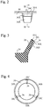
- each bump 36 is arranged at a position that abuts the distal edge 30A of the seal lip 30.
- Each bump 36 has a parallel surface 36A, an inclined surface 36B, and a perpendicular surface 36C.
- the parallel surface 36A is a flat surface parallel to the inner peripheral surface of the seal lip 30.
- the inclined surface 36B is continuous with the parallel surface 36A, and the height thereof gradually decreases from the parallel surface 36A toward the inner peripheral surface of the seal lip 30.
- the perpendicular surface 36C is perpendicular to the inner peripheral surface of the parallel surface 36A and the seal lip 30, and is flush with the distal edge 30A of the seal lip 30.
- Fig. 4 there are provided three sets including two bumps 36.
- the three sets are equiangularly spaced; in other words, are spaced 120 degrees apart from one another.
- the arrangement and the number of the bumps 36 are not limited to this embodiment.
- the bumps 36 are always in slidable contact with the outer peripheral surface of the cylindrical part 12A of the oil stopping member 12.
- the seal lip 30 slidably contacts the outer peripheral surface of the cylindrical part 12A of the oil stopping member 12, and acts to seal the lubricant inside the rolling bearing 2, resulting in a superior ability to seal the lubricant.
- seal lip 30 is in contact with the entire circumference of the outer peripheral surface of the cylindrical part 12A, when the pressure inside the rolling bearing 2 rises, the seal lip 30 is pressed against the outer peripheral surface of the cylindrical part 12A of the oil stopping member 12, thereby resulting in an increase in friction, and a consequent likelihood of heat being generated.
- each bump 36 includes the parallel surface 36A, which is parallel to the inner peripheral surface of the seal lip 30, and the inclined surface 36B of which the heigh gradually decreases from the parallel surface 36A toward the inner peripheral surface of the seal lip 30. Accordingly, as described below, it is easy to form each bump 36 to have a target height relative to the inner peripheral surface of the seal lip 30.
- the inner sealing member 20 in which the bumps 36 are formed can be shaped by use of, for example, a mold. Injection molding or press molding may be used to shape the inner sealing member 20, for example.
- Fig. 5 is a cross-sectional view of the seal lip 30 formed by use of a mold.
- a trace portion 37 is formed integral with the seal lip 30.
- the trace portion 37 is a trace of the material path in the mold that spreads the elastic material in the desired cavity.
- the trace portion 37 extends from the seal lip 30 and has a portion that extends from the bump 36.
- the parallel surface 36A of a bump 36 is not parallel to the inner peripheral surface of the seal lip 30 and lies on an extended surface of the inclined surface 36B, and the cutting position in the finish forming is not the target position, the height h of the bump 36 relative to the inner peripheral surface of the seal lip 30 will not be the target height. Accordingly, highly close attention is required cutting process.
- each bump 36 has a parallel surface 36A that is parallel to the inner peripheral surface of the seal lip 30. Accordingly, even if the cutting position deviates from the target position, the height h of the bump 36 (the distance between the parallel surface 36A and the inner peripheral surface of the seal lip 30) relative to the inner peripheral surface of the seal lip 30 will have the target height.
- the parallel surface 36A of the bump 36 is not essential.
- minute convexities and concavities be formed on the inner peripheral surface of the seal lip 30 including the bumps 36.
- the minute convexities and concavities can be irregularly formed by matting.
- the minute convexities and concavities on the inner peripheral surface of the seal lip 30 reduce frictional resistance of the seal lip 30 and minimize heat generation and torque.
- the minute convexities and concavities of the inner peripheral surface of the seal lip 30 create minute gaps between the seal lip 30 and the outer peripheral surface of the cylindrical part 12A of the oil stopping member 12. Air flows through the minute gaps, to/from the inside of the rolling bearing 2 (bearing inner side B) and from/to the outside of the rolling bearing 2 (atmosphere side A). Accordingly, even when the internal pressure in the rolling bearing 2 rises, the seal lip 30 is not pressed against the outer peripheral surface of the cylindrical part 12A of the oil stopping member 12, thereby reducing a likelihood of heat generation due to an increase in friction.
- the ten point height of irregularities Rz of the inner peripheral surface of the seal lip 30 having minute convexities and concavities is preferably 15 ⁇ m or more and 30 ⁇ m or less. In a case in which the roughness of the inner peripheral surface of the seal lip 30 is less than 15 ⁇ m, the minute gaps are small and air flow is small. On the other hand, in a case in which the roughness of the inner peripheral surface of seal lip 30 is greater than 30 ⁇ m, the lubricant may leak from the inside of the rolling bearing 2 to the outside through the minute gaps.
- the distal end of the auxiliary lip 32 slidably contacts the outer peripheral surface of the cylindrical part 12A of the oil stopping member 12.
- the distal end of the auxiliary lip 32 need not contact the oil stopping member 12, in which case an annular clearance will exist between the distal end of the auxiliary lip 32 and the oil stopping member 12. If the clearance is small, the auxiliary lip 32 can prevent or reduce ingress of foreign matter from the atmosphere side A to the bearing inner side B.
- the distal end of the side lip 34 slidably contacts the inner peripheral surface of the outer cylindrical part 12C of the oil stopping member 12, but the distal end of the side lip 34 need not contact the oil stopping member 12. In this case, there will be an annular clearance between the distal end of the side lip 34 and the oil stopping member 12, but if the clearance is small, the side lip 34 can prevent or reduce ingress of foreign matter from the atmosphere side A to the bearing inner side B.
- auxiliary lip 32 In the embodiment in which the distal end of the auxiliary lip 32 slidably contacts the outer peripheral surface of the cylindrical part 12A of the oil stopping member 12, multiple bumps 38 are also formed on the inner peripheral surface of the auxiliary lip 32.
- the bumps 38 are always in slidable contact with the outer peripheral surface of the cylindrical part 12A of the oil stopping member 12.
- auxiliary lip 32 Accordingly, whereas an ability of the auxiliary lip 32 to seal the lubricant is high, even if the pressure inside the rolling bearing 2 falls, the auxiliary lip 32 is not strongly attracted to the outer peripheral surface of the cylindrical part 12A, and the risk of heat generation is reduced.
- the bumps 38 can be provided in a manner similar to that of the bumps 36, and the three sets can be equiangularly spaced; in other words, spaced 120 degrees apart from one another.
- the arrangement and the number of the bumps 38 are not limited to this embodiment.
- each bump 38 does not have a parallel surface corresponding to the parallel surface 36A of each bump 36, and has only a surface inclined relative to the inner peripheral surface of the auxiliary lip 32.
- each bump 38 may be placed at a position that abuts the distal edge of the auxiliary lip 32, and a parallel surface corresponding to the parallel surface 36A of each bump 36 may be provided on each bump 38. In this case, it is easy to form each bump 38 to have a target height relative to the inner peripheral surface of the auxiliary lip 32.
- minute convexities and concavities be formed on the inner peripheral surface of the auxiliary lip 32 including the bumps 38.
- the minute convexities and concavities can be irregularly formed by matting.
- the minute convexities and concavities on the inner peripheral surface of the auxiliary lip 32 reduce frictional resistance of the auxiliary lip 32 and minimize heat generation and torque.
- the ten point height of irregularities Rz of the inner peripheral surface of the auxiliary lip 32 having minute convexities and concavities is preferably 15 ⁇ m or more and 30 ⁇ m or less. In a case in which the ten point height of irregularities Rz of the inner peripheral surface of the auxiliary lip 32 is equal to or greater than 15 ⁇ m and is equal to or less than 30 ⁇ m, sealing of the lubricant by the auxiliary lip 32 and air flow can both be achieved.
- the bumps 40 In a manner similar to that of the bumps 36, there can be provided three sets including two bumps 40, and the three sets can be equiangularly spaced; in other words, spaced 120 degrees apart from one another.
- the arrangement and the number of the bumps 40 are not limited to this embodiment.
- each bump 40 does not have a parallel surface corresponding to the parallel surface 36A of each bump 36, and only has a surface inclined relative to the outer peripheral surface of the side lip 34.
- each bump 40 may be placed at a position that abuts the distal edge of the side lip 34, and a parallel surface corresponding to the parallel surface 36A of each bump 36 may be provided on each bump 40. In this case, it is easy to form each bump 40 such that it has a target height relative to the outer peripheral surface of the side lip 34.
- minute convexities and concavities be formed on the outer peripheral surface of the side lip 34 including the bumps 40.
- the minute convexities and concavities can be irregularly formed by matting.
- the minute convexities and concavities on the outer peripheral surface of the side lip 34 reduce the frictional resistance of the side lip 34 and minimize heat generation and torque.
- the ten point height of irregularities Rz of the outer peripheral surface of the side lip 34 having minute convexities and concavities is preferably 15 ⁇ m or more and 30 ⁇ m or less. In a case in which the ten point height of irregularities Rz of the outer peripheral surface of the side lip 34 is equal to or greater than 15 ⁇ m and is equal to or less than 30 ⁇ m, sealing of the lubricant by the side lip 34 and air flow can both be achieved.
- Fig. 7 shows a sealing device 40 according to a second embodiment of the present invention.
- the same reference symbols are used to denote components already described, and such components will not be described in detail.
- the sealing device 40 is disposed between the inner race 6 and the outer race 8, which rotate relative to each other, and acts to seal the gap between the inner race 6 and the outer race 8.
- the sealing device 40 acts to prevent or reduce outflow of grease, i.e., lubricant, from the inside of the rolling bearing 2, and to prevent or reduce ingress of foreign matter from the outside to the inside of the rolling bearing 2.
- arrow D indicates an example of the flow direction of foreign matter from the outside.
- Fig. 7 only the left side with respect to the axle 4 is shown, but the sealing device 40 and the rolling bearing 2 have rotationally symmetric shapes.
- the upper side of Fig. 7 is the bearing inner side B, and the lower side is the atmosphere side A.
- another sealing device similar to the sealing device 40 is provided on the opposite side of the rolling bearing 2 from the sealing device 40.
- the sealing device 40 includes an annular inner sealing member 41 and an annular outer sealing member 50.
- the inner sealing member 41 is fixed to the inner race 6.
- the outer sealing member 50 is fixed to the internal surface of the hole 8A of the outer race 8, and the inner sealing member 41 is in slidable contact with the outer sealing member 50.
- the inner sealing member 41 is made from a rigid material, for example, a metal.
- the inner sealing member 41 includes a sleeve 42, a flange 44, and an outer sleeve 46.
- the sleeve 42 is fixed to the inner race 6 by, for example, an interference fit method.
- the flange 44 extends radially outside from the end portion of the sleeve 42 on the atmosphere side.
- the outer sleeve 46 extends along the axial direction of the inner sealing member 41 from the outer edge of the flange 44 toward the bearing inner side B.
- the outer sealing member 50 is disposed between the outer race 8 and the inner sealing member 41, which rotate relative to each other, and acts to seal the gap between the outer race 8 and the inner sealing member 41. Accordingly, the outer sealing member 50 can be considered as a sealing device.
- the outer sealing member (sealing device) 50 has a composite structure that includes a rigid part 52 formed from a rigid material, for example, a metal, and an elastic part 54 formed from an elastic material, for example, an elastomer.
- the rigid part 52 is fixed to the elastic part 54 to reinforce the elastic part 54.
- the rigid part 52 includes a cylindrical section 55 fixedly engaged with the internal surface of the hole 8A of the outer race 8, a circular annular section 56, multiple axial direction projections 57, and multiple inner extending sections 58.
- the cylindrical section 55 is engaged with the internal surface of the hole 8A of the outer race 8 by interference fit.
- the end portion 55a on the bearing inner side B of the cylindrical section 55 is hook-shaped and extends radially outward.
- a circumferential groove, that is, a concave portion 8C is formed in the hole 8A, in which the end portion 55a of the cylindrical section 55 is engaged.
- the circular annular section 56 extends radially inward from the end portion of the cylindrical section 55 on the atmosphere side A.
- the circular annular section 56 lies on a plane perpendicular to the axial direction of the outer sealing member 50.
- the axial direction projections 57 protrude along the axial direction of the outer sealing member 50 from the circular annular section 56 toward the atmosphere side A.
- the axial direction projections 57 have shapes in which multiple portions spaced apart at angular intervals from one another in the circumferential direction in the circular annular section 56 are folded.
- multiple portions in the circular annular section 56 at which the multiple axial direction projections 57 are not formed are continuous with multiple inner extending sections 58 that extend radially inward from the circular annular section 56.
- the axial direction projections 57 are arranged at equiangular intervals and the inner extending sections 58 are also arranged at equiangular intervals, but the angular intervals need not be equal.
- eight axial direction projections 57 and eight inner extending sections 58 are provided, but the number of axial direction projections 57 and the number of inner extending sections 58 may be an unlimited number of two or more.
- a recess 59 that extends inward in the radial direction is formed on the radial outer surface of each axial direction projection 57.
- the recesses 59 are through-holes, but the recesses 59 need not penetrate the axial direction projections 57.
- the elastic part 54 includes an annular proximal section 60 supported by the rigid part 52, a seal lip (grease lip) 62, a dust lip (side lip) 64, a radial direction protrusion 66, and a tubular wall section 68.
- the proximal section 60 of the elastic part 54 is an annular section located radially inward of the axial direction projections 57 of the rigid part 52, and is fixed to the inner extending sections 58 of the rigid part 52.
- the inner extending sections 58 that are intermittently arranged in the circumferential direction are embedded in the annular proximal section 60 that is continuous in the circumferential direction, so that the inner extending sections 58 reinforce the proximal section 60.
- the seal lip 62 is a plate-like ring that extends from the proximal section 60 and is in slidable contact with the outer peripheral surface of the sleeve 42 of the inner sealing member 41. Primarily, the seal lip 62 acts to prevent or reduce leakage of the lubricant from the bearing inner side B to the atmosphere side A.
- the seal lip 62 has a proximal end portion 62a shaped as a truncated cone ring that extends from the proximal section 60 toward the atmosphere side A and radially inward, and a distal end portion 62b shaped as a truncated cone ring and that obliquely extends from the proximal end portion 62a toward the bearing inner side B and radially inward.
- the distal end of the distal end portion 62b is in contact with the outer peripheral surface of the sleeve 42 of the inner sealing member 41 so as to be slidable over the entire circumference.
- the thickness of the proximal end portion 62a is greater than the thickness of the distal end portion 62b.
- the dust lip 64 is a plate-like ring that extends from the proximal section 60 and is in slidable contact with the side surface of the flange 44 of the inner sealing member 41 on the bearing inner side B. Primarily, the dust lip 64 acts to prevent or reduce ingress of foreign matter from the atmosphere side A to the bearing inner side B.
- the dust lip 64 has a proximal end portion 64a that extends from the proximal section 60 toward the atmosphere side A and radially inward, and a distal end portion 64b that extends from the proximal end portion 64a toward the atmosphere side A and radially outward.
- the distal end portion 64b extends toward the side surface on the bearing inner side B of the flange 44 of the inner sealing member 41.
- the thickness of the proximal end portion 64a is greater than the thickness of the distal end portion 64b.
- the radial direction protrusion 66 protrudes radially inward from the inner edge of the proximal section 60.
- the radial direction protrusion 66 has a trapezoidal cross section with a width that is broader at the radial outer side and narrower at the radial inner side.
- the radial direction protrusion 66 is not in contact with the inner sealing member 41, and a small annular clearance 69 is provided between the radial direction protrusion 66 and the sleeve 42 of the inner sealing member 41.
- the clearance 69 assists the sealing ability of the seal lip 62 by impeding flow of lubricant from the bearing inner side B to the atmosphere side A and reducing the amount of lubricant reaching the seal lip 62.
- the tubular wall section 68 is a cylindrical section that extends from the outer edge of the proximal section 60 toward the flange 44 of the inner sealing member 41, and is fixed to the multiple axial direction projections 57 of the rigid part 52.
- the axial direction projections 57 which are arranged intermittently in the circumferential direction, are embedded in the cylindrical tubular wall section 68 that is continuous in the circumferential direction, so that the axial direction projections 57 reinforce the tubular wall section 68.
- the elastic part 54 not only the inner extending sections 58 of the rigid part 52, but also a part of the circular annular section 56 and the entirety of the axial direction projections 57 are embedded. Specifically, a part of the surface on the atmosphere side A of the circular annular section 56 is covered by a portion 70 of the elastic part 54, and a part of the surface on the bearing inner side B of the circular annular section 56 is covered by a portion 72 of the elastic part 54, whereas the axial direction projections 57 are covered by the tubular wall section 68 of the elastic part 54.
- the circular annular section 56 need not be covered with an elastic material.
- the tubular wall section 68 is not in contact with the flange 44, and an annular clearance 74 is provided between the tubular wall section 68 and the flange 44.
- the outer sleeve 46 of the inner sealing member 41 is located outside the tubular wall section 68.
- the tubular wall section 68 is not in contact with the outer sleeve 46, and an annular clearance 76 is provided between the tubular wall section 68 and the outer sleeve 46.
- the elastic part 54 occludes the recesses 59 formed in the axial direction projections 57.
- portions 72 of the elastic part 54 that occlude the recesses 59 are concave.
- the material of the elastic part 54 greatly contracts in the vicinity of the recesses 59, so that the portions 72 become concave.
- the jig 80 has an elongated handle part 80a and a distal end part 80b that is bent relative to the handle part 80a. A mechanic grips the handle part 80a.
- the recesses 59 are captured by the jigs 80 by inserting the distal end part 80b of each jig 80 into a recess 59 formed in an axial direction projection 57 of the rigid part 52 of the outer sealing member 50 of the sealing device 40.
- the portions are greatly compressed by the distal end parts 80b. Breakage of the portions is allowed.
- the outer sealing member 50 is then moved along the axial direction by pulling the jigs 80, the distal end portions 80b of which are inserted into the recesses 59, with a force S, whereby the outer sealing member 50 can be extracted from the hole 8A of the outer race 8 of the rolling bearing 2.
- the outer sealing member 50 can be extracted with ease from the hole 8A of the outer race 8 of the rolling bearing 2 under elastic deformation of the outer sealing member 50.
- the flange 44 is pushed by the tubular wall section 68 of the outer sealing member 50, so that the inner sealing member 41 fixed to the inner race 6 can also be extracted together with the outer sealing member 50.
- the sealing device 40 can be removed with ease.
- the outer sealing member 50 and the inner sealing member 41 need not necessarily be removed at the same time, and the outer sealing member 50 may be pulled out from the outer race 8 after the inner sealing member 41 is pulled out from the inner race 6.
- This removal operation uses multiple jigs 80, but a mechanic may manually perform the operation instead of the jigs 80. Even when multiple jigs 80 are used, the jigs 80 may be used to pull out only the outer sealing member 50 from the hole 8A of the outer race 8 by applying the force S to the outer sealing member 50. In other words, the outer sealing member 50 may be compressed in radial directions by applying forces F radially inward to the outer sealing member 50 either manually by the mechanic or by use of other jigs.
- the recesses 59 into which the jigs 80 are inserted are arranged at multiple locations separated by angular intervals in a circumferential direction. Each recess 59 is covered by a portion 72 of the elastic part 54. To insert the jig 80 or the mechanic's hand into one of the recesses 59, it is desirable to be able to easily locate the recess 59.
- each mark 82 is a hemispherical protrusion, but the shape of the mark 82 is not limited thereto, and may be a protrusion of another shape, a recess, or an engraved mark. Moreover, the mark 82 is not limited to a three-dimensional shape, and may be a visually recognizable colored or patterned mark on a plane.
- multiple bumps 84 are formed on the distal end portion 62b of the side lip 62.
- the bumps 84 are always in slidable contact with the outer peripheral surface of the sleeve 42 of the inner sealing member 41.
- the seal lip 62 slidably contacts the outer peripheral surface of the sleeve 42 and seals the lubricant inside the rolling bearing 2, resulting in a superior ability to seal lubricant.
- multiple bumps 84 formed on the inner peripheral surface of the seal lip 62 are always in slidable contact with the outer peripheral surface of the sleeve 42, and small clearances exist between the seal lip 62 and the outer peripheral surface of the sleeve 42.
- each bump 84 preferably has a parallel surface 84A that is parallel to the inner peripheral surface of the distal end portion 62b of the seal lip 62, and an inclined surface 84B of which the height gradually decreases from the parallel surface 84A toward the inner peripheral surface of the distal end portion 62b of the seal lip 62. In this case, it is easy to form each bump 84 such that it has a target height relative to the inner peripheral surface of the seal lip 62.
- minute convexities and concavities are formed on the inner peripheral surface, which includes the bumps 84, of the distal end portion 62b of the seal lip 62.
- the ten point height of irregularities Rz of the inner peripheral surface of the seal lip 62 having minute convexities and concavities is preferably 15 ⁇ m or more and 30 ⁇ m or less.
- the dust end portion 64b of the dust lip 64 is not in contact with the flange 44 of the inner sealing member 41, and therefore, an annular clearance is provided between the distal end portion 64b and the flange 44.
- the distal end portion 64b of the dust lip 64 may be in contact with the flange 44 of the inner sealing member 41, and in this case, multiple bumps (not shown) preferably are formed on the inner peripheral surface of the distal end portion 64b of the dust lip 64 such that the bumps are always in slidable contact with the flange 44.
- each bump preferably has a parallel surface that is parallel to the inner peripheral surface of the distal end portion 64b of the dust lip 64, and an inclined surface of which the height gradually decreases from the parallel surface toward the inner peripheral surface of the distal end portion 64b of the seal lip 64.
- minute convexities and concavities are preferably formed on the inner peripheral surface, which includes the bumps, of the distal end portion 64b of the dust lip 64.
- the ten point height of irregularities Rz of the inner peripheral surface of the seal lip 62_having minute convexities and concavities is preferably 15 ⁇ m or more and 30 ⁇ m or less.
- Fig. 10 shows a sealing device 90 according to a third embodiment of the present invention.
- the sealing device 90 is disposed between the inner race 6 and the outer race 8, which rotate relative to each other, and acts to seal the gap between the inner race 6 and the outer race 8.
- the sealing device 90 prevents or reduces the outflow of grease, i.e., lubricant, from the inside of the rolling bearing 2, and prevents or reduces the ingress of foreign matter from the outside to the inside of the rolling bearing 2.
- arrow D indicates an example of the flow direction of foreign matter from the outside.
- Fig. 10 only the left side with respect to the axle 4 is shown, but the sealing device 90 and the rolling bearing 2 have symmetric rotational shapes.
- the upper side of Fig. 10 is the bearing inner side B, and the lower side is the atmosphere side A.
- another sealing device similar to the sealing device 90 is provided on the opposite side of the rolling bearing 2 from the sealing device 90.
- the sealing device 90 includes four annular sealing members, i.e., an outer sealing member 16, an intermediate sealing member 18, an inner sealing member 91, and a slinger 110.
- the outer sealing member 16 and the intermediate sealing member 18 of this embodiment are almost the same as those in the first embodiment, except that the circular annular section 16D of the outer sealing member 16 of this embodiment is inclined and has a truncated cone shape.
- the slinger 110 is formed from a rigid material such as a metal.
- the slinger 110 includes a sleeve 112, a flange 114, and an outer sleeve 116.
- the sleeve 112 is to be mounted to the inner race 6, by use of an interference fit method, for example.
- the flange 114 extends radially outward from the end on the atmosphere side of the sleeve 112.
- the outer sleeve 116 extends from the outer edge of the flange 114 to the bearing inner side B along the axial direction of the slinger 110.
- An annular clearance 117 is provided between the outer sleeve 116 and the inner cylindrical section 16E of the outer sealing member 16, and another annular gap 118 is provided between the end of the bearing inner side B of the sleeve 112 and the inner cylindrical section 18C of the intermediate sealing member 18.
- the inner sealing member 91 is arranged inside the outer sealing member 16 and the intermediate sealing member 18, and is disposed between the outer sealing member 16 and the slinger 110, which rotate relative to each other to seal the gap between the outer sealing member 16 and the slinger 110. Accordingly, the inner sealing member 91 can be considered as a sealing device.
- the inner sealing member (sealing device) 91 has a composite structure that includes a rigid part 92 formed from a rigid material, for example, a metal, and an elastic part 93 formed from an elastic material, for example, an elastomer.
- the elastic part 93 is fixed to the rigid part 92 to reinforce the elastic part 93.
- the inner sealing member 91 includes a mounted cylindrical section 94 that is to be mounted to the intermediate sealing member 18, a circular annular section 95, a seal lip (grease lip) 96, an auxiliary lip (dust lip) 97, and a side lip (dust lip) 98.
- the mounted cylindrical section 94 has a rigid part 92 and an elastic part 93, and is fixed to the inner peripheral surface of the outer cylindrical section 18A of the intermediate sealing member 18 by an interference fit.
- the circular annular section 95 has a rigid part 92 and an elastic part 93, and extends radially inward from the mounted cylindrical section 94.
- the elastic part 93 includes lips 96, 97, and 98.
- the seal lip 96 is a radial lip shaped as a truncated cone ring, and extends diagonally (radially inward and toward the bearing inner side B) from the inner end of the circular annular section 95.
- the seal lip 96 extends toward the outer peripheral surface of the sleeve 112 of the slinger 110, and the distal end of the seal lip 96 is in contact with the outer peripheral surface of the sleeve 112 so as to be slidable over the entire circumference.
- the seal lip 96 acts to prevent or reduce leakage of the lubricant from the bearing inner side B to the atmosphere side A.
- the auxiliary lip 97 is a radial lip shaped as a truncated cone ring, and extends diagonally (radially inward and toward the atmosphere side A) from the inner end of the circular annular section 95.
- the auxiliary lip 97 is located inside the outer sleeve 116 of the slinger 110, and extends to the outer peripheral surface of the sleeve 112 of the slinger 110.
- the distal end of the auxiliary lip 97 is in contact with the outer peripheral surface of the sleeve 112 of the slinger 110 so as to be slidable over the entire circumference.
- the auxiliary lip 97 acts to prevent or reduce ingress of foreign matter from the atmosphere side A to the bearing inner side B, and also acts to prevent or reduce leakage of the lubricant from the bearing inner side B to the atmosphere side A.
- the side lip 98 is a radial lip shaped as a truncated cone ring, and extends diagonally (radially outward and toward the atmosphere side A) from the circular annular section 95.
- the side lip 98 is located inside the outer sleeve 116 of the slinger 110, and extends to the inner peripheral surface of the outer sleeve 116 of the slinger 110.
- the distal end of the side lip 98 is in contact with the inner peripheral surface of the outer sleeve 116 of the slinger 110 so as to be slidable over the entire circumference.
- the side lip 98 acts to prevent or reduce ingress of foreign matter from the atmosphere side A to the bearing inner side B, and also acts to prevent or reduce leakage of the lubricant from the bearing inner side B to the atmosphere side A.
- multiple bumps 100 are formed on the inner peripheral surface of the seal lip 96 in this embodiment.
- the bumps 100 are always in slidable contact with the outer peripheral surface of the sleeve 112 of the slinger 110.
- the seal lip 96 slidably contacts the outer peripheral surface of the sleeve 112 and seals the lubricant inside the rolling bearing 2, resulting in a superior ability to seal lubricant.
- multiple bumps 100 formed on the inner peripheral surface of the seal lip 96 are always in slidable contact with the outer peripheral surface of the sleeve 112, and small clearances exist between the seal lip 96 and the outer peripheral surface of the sleeve 112.
- each bump 100 preferably has a parallel surface 100A that is parallel to the inner peripheral surface of the seal lip 96, and an inclined surface 100B having a height gradually decreases from the parallel surface 100A toward the inner peripheral surface of the seal lip 96. In this case, it is easy to form each bump 100 such that it has a target height relative to the inner peripheral surface of the seal lip 96.
- minute convexities and concavities are formed on the inner peripheral surface, which includes the bumps 100, of the seal lip 96.
- the ten point height of irregularities Rz of the inner peripheral surface of the seal lip 96 having minute convexities and concavities is preferably 15 ⁇ m or more and 30 ⁇ m or less.
- the distal end of the auxiliary lip 97 is in slidable contact with the outer peripheral surface of the sleeve 112 of the slinger 110.
- the distal end of the auxiliary lip 97 need not be in contact with the slinger 110, in which case, there will be an annular clearance between the distal end of the auxiliary lip 97 and the slinger 110. If the clearance is small, the auxiliary lip 97 can prevent or reduce ingress of foreign matter from the atmosphere side A to the bearing inner side B.
- the distal end of the side lip 98 slidably contacts the inner peripheral surface of the outer sleeve 116 of the slinger 110, but the distal end of the side lip 98 need not contact the slinger 110. In this case, there will be an annular clearance between the distal end of the side lip 98 and the slinger 110, but if the clearance is small, the side lip 98 can prevent or reduce ingress of foreign matter from the atmosphere side A to the bearing inner side B.
- auxiliary lip 97 In the embodiment in which the distal end of the auxiliary lip 97 slidably contacts the outer peripheral surface of the sleeve 112 of the slinger 110, multiple bumps 102 are also formed on the inner peripheral surface of the auxiliary lip 97.
- the bumps 102 are always in slidable contact with the outer peripheral surface of the sleeve 112 of the slinger 110.
- each bump 102 does not have a parallel surface corresponding to the parallel surface 100A of each bump 100, and has only a surface inclined relative to the inner peripheral surface of the auxiliary lip 97.
- each bump 102 may be placed at a position that abuts the distal edge of the auxiliary lip 97, and a parallel surface corresponding to the parallel surface 100A of each bump 100 may be provided on each bump 102. In this case, it is easy to form each bump 102 such that it has a target height relative to the inner peripheral surface of the auxiliary lip 97.
- minute convexities and concavities be formed on the inner peripheral surface of the auxiliary lip 97 that includes the bumps 102.
- the ten point height of irregularities Rz of the inner peripheral surface of the auxiliary lip 97 having minute convexities and concavities is preferably 15 ⁇ m or more and 30 ⁇ m or less.
- multiple bumps 104 are also formed on the outer peripheral surface of side lip 98.
- the bumps 104 are always in slidable contact with the inner peripheral surface of the outer sleeve 116 of the slinger 110.
- each bump 104 does not have a parallel surface corresponding to the parallel surface 36A of each bump 36, and has only a surface inclined relative to the outer peripheral surface of the side lip 98.
- each bump 104 may be placed at a position that abuts the distal edge of the side lip 98, and a parallel surface corresponding to the parallel surface 36A of each bump 36 may be provided on each bump 104. In this case, it is easy to form each bump 104 such that it has a target height relative to the outer peripheral surface of the side lip 98.
- minute convexities and concavities be formed on the inner peripheral surface of the side lip 98 that includes the bumps 104.
- the ten point height of irregularities Rz of the inner peripheral surface of the side lip 98 having minute convexities and concavities is preferably 15 ⁇ m or more and 30 ⁇ m or less.
- the shape and number of lips of the sealing device are not limited to those described above.
- the inner race 6 and the oil stopping member 12, which are the inner members, are rotating members
- the outer race 8, which is the outer member is a stationary member.
- the present invention is not limited to the above embodiments, and is applicable to sealing multiple members that rotate relative to each other.
- the inner members may be stationary, and the outer member may rotate, or all of the members may rotate.
- each of the bumps comprises a parallel surface that is parallel to the inner peripheral surface of the seal lip, and an inclined surface continuing from the parallel surface, the inclined surface having a height that decreases from the parallel surface to the inner peripheral surface.
- each bump has a surface that is parallel to the inner peripheral surface of the seal lip, even if a cutting position deviates from a target position when the seal lip is finished together with the bumps after the seal lip with the bumps is shaped, e.g., by use of a mold, the height of the bumps (the distance between the parallel surface and the inner peripheral surface) will have the target height.
- minute convexities and concavities on the inner peripheral surface of the seal lip reduce frictional resistance of the seal lip and minimize heat generation and torque.
- the minute convexities and concavities of the inner peripheral surface of the seal lip create minute gaps between the seal lip and the inner member or the member fixed to the inner member. Air flows through the minute gaps to/from the inside of the bearing and from/to the outside of the bearing, so that the seal lip and/or another lip are not pressed against or attracted to the inner member or the member fixed to the inner member, thereby reducing a likelihood of heat generation due to an increase in friction even when the internal pressure in the bearing rises or falls.
- the roughness of the inner peripheral surface with the minute convexities and concavities is sufficient, and therefore, sealing of the lubricant by the seal lip and air flow can both be achieved.
- Clause 5 The sealing device according to any one of clauses 1 to 4, wherein the elastic part comprises a dust lip shaped as a truncated cone ring that is to be in slidable contact with the inner member or a member fixed to the inner member, convexities and concavities being formed on an inner peripheral surface of the dust lip.
- the elastic part comprises a dust lip shaped as a truncated cone ring that is to be in slidable contact with the inner member or a member fixed to the inner member, convexities and concavities being formed on an inner peripheral surface of the dust lip.
- minute convexities and concavities on the inner peripheral surface of the dust lip reduce frictional resistance of the dust lip and minimize heat generation and torque.
- the minute convexities and concavities of the inner peripheral surface of the dust lip create minute gaps between the dust lip and the inner member or the member fixed to the inner member. Air flows through the minute gaps to/from the inside of the bearing and from/to the outside of the bearing, so that the dust lip is not attracted to the inner member or the member fixed to the inner member, thereby reducing a likelihood of heat generation due to an increase in friction even when the internal pressure in the bearing rises or falls.
- the roughness of the inner peripheral surface with the minute convexities and concavities is sufficient, and therefore, sealing of the lubricant by the dust lip and air flow can both be achieved.
Landscapes
- Engineering & Computer Science (AREA)
- General Engineering & Computer Science (AREA)
- Mechanical Engineering (AREA)
- Physics & Mathematics (AREA)
- Fluid Mechanics (AREA)
- Sealing Of Bearings (AREA)
- Rolling Contact Bearings (AREA)
- Sealing With Elastic Sealing Lips (AREA)
- Sealing Devices (AREA)
Abstract
Description
- The present invention relates to sealing devices for interior sealing of rolling bearings.
-
Patent Document 1 discloses a rolling bearing suitable for use in railroad vehicles. The interior of the rolling bearing is subject to temperature variations due to heat generated by friction between rolling elements and surrounding elements, resulting in changes in pressure inside the rolling bearing. The rolling bearing is provided with sealing devices for sealing lubricant therein, and the sealing devices are in slidable contact with the rotating inner race. Upon a change in pressure inside the bearing, a strong force acts on the sealing devices in contact with the inner race, and heat is generated by friction. To minimize heat generation, the bearing disclosed inPatent Document 1 is provided with a plug for venting air. - Patent Document 1:
Japanese Utility Model Publication 4-123871 - Another approach for minimizing heat generation in a bearing is conceived in which a countermeasure for reducing heat generation is applied to a sealing device within the bearing, rather than to the bearing. In this case, it is desirable to ensure that the ability of the sealing device to seal a lubricant (grease) within the bearing, which is the original function of the device, is not compromised.
- Accordingly, the present invention provides a sealing device that has a superior ability to seal a lubricant and that is capable of reducing a likelihood of heat generation due to an increase in friction even when an internal pressure in a bearing rises or falls.
- According to an aspect of the present invention, a sealing device is disposed between an inner member and an outer member of a rolling bearing, which rotate relative to each other, for sealing a gap between the inner member and the outer member. The sealing device includes an annular rigid part that is to be fixed to an inside of a hole of the outer member, the rigid part being made from a rigid material; and an elastic part fixed to the rigid part, the elastic part being made from an elastic material. The elastic part includes a seal lip shaped as a truncated cone ring that is to be in slidable contact with the inner member or a member fixed to the inner member. Multiple bumps are formed on an inner peripheral surface of the seal lip. The bumps are always in slidable contact with the inner member or the member fixed to the inner member, and clearances are provided between the seal lip and the inner member or the member fixed to the inner member in vicinities of the bumps.
- In this aspect, the seal lip, which is in slidable contact with the inner member or a member fixed to the inner member, seals the lubricant inside the bearing, resulting in a superior ability to seal the lubricant. On the other hand, multiple bumps formed on the inner peripheral surface of the seal lip are always in slidable contact with the inner member or the member fixed to the inner member, and small clearances exist between the seal lip and the inner member or the member fixed to the inner member in vicinities of the bumps. Air flows through the small clearances to/from the inside of the bearing and from/to the outside of the bearing, so that the seal lip and/or another lip are not pressed against or attracted to the inner member or the member fixed to the inner member, thereby reducing a likelihood of heat generation due to an increase in friction even when the internal pressure in the bearing rises or falls.
-
-
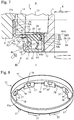
Fig. 1 is a cross-sectional view of a sealing device according to a first embodiment of the present invention; -
Fig. 2 is a front view of a bump in the sealing device ofFig. 1 ; -
Fig. 3 is a cross-sectional view taken along line III-III inFig. 2 ; -
Fig. 4 is a drawing showing an arrangement of bumps in a seal lip of the sealing device ofFig. 1 ; -
Fig. 5 is a cross-sectional view of the seal lip formed with a mold; -
Fig. 6 is a front view showing a part of the seal lip; -
Fig. 7 is a cross-sectional view of a sealing device according to a second embodiment of the present invention; -
Fig. 8 is a perspective view showing a rigid body part of the sealing device inFig. 7 ; -
Fig. 9 is a cross-sectional view showing the sealing device ofFig. 7 in removal from a rolling bearing; and -
Fig. 10 is a cross-sectional view of a sealing device according to a third embodiment of the present invention. - Hereinafter, with reference to the accompanying drawings, various embodiments according to the present invention will be described. It is of note that the drawings do not necessarily accurately show relative dimensional ratios of actual products according to the embodiments and some dimensions may be exaggerated.
-
Fig. 1 shows a bearing for an axle of a railroad vehicle, which is an example of a rolling bearing 2 in which asealing device 1 according to a first embodiment of the present invention is used. The present invention is not limited to bearings for railroad vehicles, and is applicable to axle bearings of large automotive vehicles such as trucks and buses. The illustrated rollingbearing 2 is an RCT (Rotating End Cap Tapered Roller) bearing. However, use of the present invention is not limited to RCT bearings, and the present invention is also applicable to other rolling bearings having other types of rolling elements, such as RCC (Rotating End Cap) bearings, ball bearings, and needle bearings. - As shown in
Fig. 1 , the rollingbearing 2 includes an inner race (inner member) 6 into which anaxle 4 is inserted, an outer race (outer member) 8 arranged outside theinner race 6,multiple rollers 10 aligned in a row between theinner race 6 and theouter race 8, an oil stopping member (inner member) 12 into which theaxle 4 is to be inserted, and aretainer 14 that retains the row of therollers 10 in a fixed position. Whereas theouter race 8 is stationary, theinner race 6 and theoil stopping member 12 rotate with rotation of theaxle 4. Theretainer 14 is fixed to theouter race 8. - The
oil stopping member 12 includes acylindrical part 12A with an outer diameter and an inner diameter that are the same as those of theinner race 6, aflange 12B extending from the end on the atmosphere side A of thecylindrical part 12A, and an outercylindrical part 12C extending from the outer edge of theflange 12B toward the bearing inner side B. Thecylindrical part 12A, theflange 12B, and the outercylindrical part 12C define acircumferential groove 12D. InFig. 1 , theoil stopping member 12 is depicted by phantom lines. - The
sealing device 1 is located between theoil stopping member 12 and theouter race 8, which rotate relative to each other, and acts to seal the gap between theoil stopping member 12 and theouter race 8. Thesealing device 1 acts to prevent or reduce outflow of grease, i.e., lubricant, from the inside of the rollingbearing 2, and to prevent or reduce ingress of foreign matter (water, including muddy water and salt water) and/or dust (including iron dust)) from the outside to the inside of the rollingbearing 2. InFig. 1 , arrow D indicates an example of the flow direction of foreign matter from the outside. - In
Fig. 1 , only the left side with respect to theaxle 4 is shown, but the rotational shapes ofsealing device 1 and the rollingbearing 2 are symmetric. The upper side ofFig. 1 is the bearing inner side B, and the lower side is the atmosphere side A. However, another sealing device similar to thesealing device 1 is provided on the opposite side of the rollingbearing 2 from thesealing device 1. - The
sealing device 1 includes three annular sealing members, i.e., anouter sealing member 16, anintermediate sealing member 18, and aninner sealing member 20. - The
outer sealing member 16 is made from a rigid material such as a metal. Theouter sealing member 16 includes an outercylindrical section 16A that is to be fixedly engaged in thehole 8A of theouter race 8, a circularannular section 16B, an intermediatecylindrical section 16C, a circularannular section 16D, and an innercylindrical section 16E. Thecylindrical sections - The outer
cylindrical section 16A is fixedly engaged in the inner peripheral surface of thehole 8A of theouter race 8 by interference fit. The end portion 16Aa on the bearing inner side B of the outercylindrical section 16A is hook-shaped and extends radially outward. Aridge 8B extending in a circumferential direction is formed in thehole 8A, and a circumferential groove into which theridge 8B is fitted is formed in the end portion 16Aa of the outercylindrical section 16A. - The circular
annular section 16B extends radially inward from the end on the atmosphere side A of the outercylindrical section 16A. The circularannular section 16B lies on a plane that is perpendicular to the axial direction of theaxle 4. - The intermediate
cylindrical section 16C extends from the inner edge of the circularannular section 16B toward the atmosphere side A. - The circular
annular section 16D extends radially inward from the end on the atmosphere side A of the intermediatecylindrical section 16C. The circularannular section 16D lies on a plane that is perpendicular to the axial direction of theaxle 4. - The inner
cylindrical section 16E extends from the inner edge of the circularannular section 16D toward the atmosphere side A. An annular clearance is provided between the inner peripheral surface of the innercylindrical section 16E and the outer peripheral surface of the outercylindrical part 12C of theoil stopping member 12. - The
intermediate sealing member 18 is formed from a rigid material, for example, a metal. Theintermediate sealing member 18 includes an outercylindrical section 18A that is to be fixed to the outer sealingmember 16, a circularannular section 18B, and an innercylindrical section 18C. The outercylindrical sections - The outer
cylindrical section 18A is engaged by interference fit with the inner peripheral surface of the intermediatecylindrical section 16C of the outer sealingmember 16. - The circular
annular section 18B extends radially inward from the end on the bearing inner side B of the outercylindrical section 18A. The circularannular section 18B generally lies on a plane that is perpendicular to the axial direction of theaxle 4, but is curved. - The inner
cylindrical section 18C extends from the inner edge of the circularannular section 18B toward the bearing inner side B. An annular clearance is provided between the inner peripheral surface of the inner cylindrical section 18c and the outer peripheral surface of thecylindrical part 12A of theoil stopping member 12. - The
inner sealing member 20 is arranged inside the outer sealingmember 16 and the intermediate sealingmember 18, and is disposed between the outer sealingmember 16 and theoil stopping member 12, which rotate relative to each other to seal the gap between the outer sealingmember 16 and theoil stopping member 12. Accordingly, the inner sealingmember 20 can be considered as a sealing device. - The inner sealing member (sealing device) 20 has a composite structure that includes a
rigid part 22 formed from a rigid material, for example, a metal, and anelastic part 24 formed from an elastic material, for example, an elastomer. Theelastic part 24 is fixed to therigid part 22, which reinforces theelastic part 24. - The
inner sealing member 20 includes a mountedcylindrical section 26 that is fixed to the intermediate sealingmember 18, a circular annular section 28, a seal lip (grease lip) 30, an auxiliary lip (dust lip) 32, and a side lip (dust lip) 34. - The mounted
cylindrical section 26 includes therigid part 22 and theelastic part 24, and is fixedly engaged with the inner peripheral surface of the outercylindrical section 18A of the intermediate sealingmember 18 by interference fit. - The circular annular section 28 includes the
rigid part 22 and theelastic part 24, and extends radially inward from the mountedcylindrical section 26. - The
elastic part 24 includeslips - The
seal lip 30 is a radial lip shaped as a truncated cone ring, and extends diagonally (radially inward and toward the bearing inner side B) from the inner end of the circular annular section 28. Theseal lip 30 extends toward the outer peripheral surface of thecylindrical part 12A of theoil stopping member 12, and the distal end of theseal lip 30 is in contact with the outer peripheral surface of thecylindrical part 12A so as to be slidable over the entire circumference. Primarily, theseal lip 30 acts to prevent or reduce leakage of the lubricant from the bearing inner side B to the atmosphere side A. - The
auxiliary lip 32 is a radial lip shaped as a truncated cone ring, and extends diagonally (radially inward and toward the atmosphere side A) from the inner end of the circular annular section 28. Theauxiliary lip 32 is located inside thecircumferential groove 12D of theoil stopping member 12, and extends to the outer peripheral surface of thecylindrical part 12A of theoil stopping member 12. In this embodiment, the distal end of theauxiliary lip 32 is in contact with the outer peripheral surface of thecylindrical part 12A of theoil stopping member 12 so as to be slidable over the entire circumference. Primarily, theauxiliary lip 32 acts to prevent or reduce ingress of foreign matter from the atmosphere side A to the bearing inner side B, but also acts to prevent or reduce leakage of the lubricant from the bearing inner side B to the atmosphere side A. - The
side lip 34 is a radial lip shaped as a truncated cone ring, and extends diagonally (radially outward and toward the atmosphere side A) from the inner end of the circular annular section 28. Theside lip 34 is located inside thecircumferential groove 12D of theoil stopping member 12, and extends to the inner peripheral surface of the outercylindrical part 12C of theoil stopping member 12. In this embodiment, the distal end of theside lip 34 is in contact with the inner peripheral surface of the outercylindrical part 12C of theoil stopping member 12 so as to be slidable over the entire circumference. Primarily, theside lip 34 acts to prevent or reduce ingress of foreign matter from the atmosphere side A to the bearing inner side B, but also acts to prevent or reduce leakage of the lubricant from the bearing inner side B to the atmosphere side A. -
Multiple bumps 36 are formed on the inner peripheral surface of theseal lip 30. As shown inFigs. 2 and 3 , eachbump 36 is arranged at a position that abuts thedistal edge 30A of theseal lip 30. Eachbump 36 has aparallel surface 36A, aninclined surface 36B, and aperpendicular surface 36C. Theparallel surface 36A is a flat surface parallel to the inner peripheral surface of theseal lip 30. Theinclined surface 36B is continuous with theparallel surface 36A, and the height thereof gradually decreases from theparallel surface 36A toward the inner peripheral surface of theseal lip 30. Theperpendicular surface 36C is perpendicular to the inner peripheral surface of theparallel surface 36A and theseal lip 30, and is flush with thedistal edge 30A of theseal lip 30. - As shown in
Fig. 4 , in this embodiment, there are provided three sets including twobumps 36. The three sets are equiangularly spaced; in other words, are spaced 120 degrees apart from one another. However, the arrangement and the number of thebumps 36 are not limited to this embodiment. - The
bumps 36 are always in slidable contact with the outer peripheral surface of thecylindrical part 12A of theoil stopping member 12. Thus, in the inner peripheral surface of theseal lip 30 shown inFig. 4 , there are provided clearances between theseal lip 30 and thecylindrical part 12A invicinities 30C of thebumps 36, althoughparts 30B that are distant from thebumps 36 are in contact with the outer peripheral surface of thecylindrical part 12A of theoil stopping member 12. - In this embodiment, as described above, the
seal lip 30 slidably contacts the outer peripheral surface of thecylindrical part 12A of theoil stopping member 12, and acts to seal the lubricant inside the rollingbearing 2, resulting in a superior ability to seal the lubricant. - On the other hand,
multiple bumps 36 formed on the inner peripheral surface of theseal lip 30 are always in slidable contact with the outer peripheral surface of thecylindrical part 12A of theoil stopping member 12, and small clearances exist between theseal lip 30 and the outer peripheral surface of thecylindrical part 12A of theoil stopping member 12 in thevicinities 30C of the bumps. - If the
seal lip 30 is in contact with the entire circumference of the outer peripheral surface of thecylindrical part 12A, when the pressure inside the rollingbearing 2 rises, theseal lip 30 is pressed against the outer peripheral surface of thecylindrical part 12A of theoil stopping member 12, thereby resulting in an increase in friction, and a consequent likelihood of heat being generated. However, in this embodiment, air flows through the small clearances between theseal lip 30 and the outer peripheral surface of thecylindrical part 12A ofoil stopping member 12, to/from the inside of the rolling bearing 2 (bearing inner side B) and from/to the outside of the rolling bearing 2 (atmosphere side A), thereby reducing a likelihood of heat generation due to an increase in friction even when the internal pressure in the rollingbearing 2 rises. - As described above, in this embodiment, each
bump 36 includes theparallel surface 36A, which is parallel to the inner peripheral surface of theseal lip 30, and theinclined surface 36B of which the heigh gradually decreases from theparallel surface 36A toward the inner peripheral surface of theseal lip 30. Accordingly, as described below, it is easy to form eachbump 36 to have a target height relative to the inner peripheral surface of theseal lip 30. - The
inner sealing member 20 in which thebumps 36 are formed can be shaped by use of, for example, a mold. Injection molding or press molding may be used to shape the inner sealingmember 20, for example.Fig. 5 is a cross-sectional view of theseal lip 30 formed by use of a mold. Immediately after molding, atrace portion 37 is formed integral with theseal lip 30. Thetrace portion 37 is a trace of the material path in the mold that spreads the elastic material in the desired cavity. Thetrace portion 37 extends from theseal lip 30 and has a portion that extends from thebump 36. By cutting the molded product at a virtual surface C to remove theunnecessary trace portion 37, theseal lip 30 can be finished together with thebumps 36. - If the
parallel surface 36A of abump 36 is not parallel to the inner peripheral surface of theseal lip 30 and lies on an extended surface of theinclined surface 36B, and the cutting position in the finish forming is not the target position, the height h of thebump 36 relative to the inner peripheral surface of theseal lip 30 will not be the target height. Accordingly, highly close attention is required cutting process. - On the other hand, in this embodiment, each
bump 36 has aparallel surface 36A that is parallel to the inner peripheral surface of theseal lip 30. Accordingly, even if the cutting position deviates from the target position, the height h of the bump 36 (the distance between theparallel surface 36A and the inner peripheral surface of the seal lip 30) relative to the inner peripheral surface of theseal lip 30 will have the target height. However, theparallel surface 36A of thebump 36 is not essential. - As shown in
Fig. 6 , it is preferable that minute convexities and concavities be formed on the inner peripheral surface of theseal lip 30 including thebumps 36. The minute convexities and concavities can be irregularly formed by matting. In this case, the minute convexities and concavities on the inner peripheral surface of theseal lip 30 reduce frictional resistance of theseal lip 30 and minimize heat generation and torque. - In addition, the minute convexities and concavities of the inner peripheral surface of the
seal lip 30 create minute gaps between theseal lip 30 and the outer peripheral surface of thecylindrical part 12A of theoil stopping member 12. Air flows through the minute gaps, to/from the inside of the rolling bearing 2 (bearing inner side B) and from/to the outside of the rolling bearing 2 (atmosphere side A). Accordingly, even when the internal pressure in the rollingbearing 2 rises, theseal lip 30 is not pressed against the outer peripheral surface of thecylindrical part 12A of theoil stopping member 12, thereby reducing a likelihood of heat generation due to an increase in friction. - The ten point height of irregularities Rz of the inner peripheral surface of the
seal lip 30 having minute convexities and concavities is preferably 15 µm or more and 30 µm or less. In a case in which the roughness of the inner peripheral surface of theseal lip 30 is less than 15 µm, the minute gaps are small and air flow is small. On the other hand, in a case in which the roughness of the inner peripheral surface ofseal lip 30 is greater than 30 µm, the lubricant may leak from the inside of the rollingbearing 2 to the outside through the minute gaps. In a case in which the ten point height of irregularities Rz of the inner peripheral surface of theseal lip 30 is equal to or greater than 15 µm and is equal to or less than 30 µm, sealing of the lubricant by theseal lip 30 and air flow can both be achieved. - As shown in
Fig. 1 , in the inner sealingmember 20 of this embodiment, the distal end of theauxiliary lip 32 slidably contacts the outer peripheral surface of thecylindrical part 12A of theoil stopping member 12. However, the distal end of theauxiliary lip 32 need not contact theoil stopping member 12, in which case an annular clearance will exist between the distal end of theauxiliary lip 32 and theoil stopping member 12. If the clearance is small, theauxiliary lip 32 can prevent or reduce ingress of foreign matter from the atmosphere side A to the bearing inner side B. - In addition, the distal end of the
side lip 34 slidably contacts the inner peripheral surface of the outercylindrical part 12C of theoil stopping member 12, but the distal end of theside lip 34 need not contact theoil stopping member 12. In this case, there will be an annular clearance between the distal end of theside lip 34 and theoil stopping member 12, but if the clearance is small, theside lip 34 can prevent or reduce ingress of foreign matter from the atmosphere side A to the bearing inner side B. - In the embodiment in which the distal end of the
auxiliary lip 32 slidably contacts the outer peripheral surface of thecylindrical part 12A of theoil stopping member 12,multiple bumps 38 are also formed on the inner peripheral surface of theauxiliary lip 32. Thebumps 38 are always in slidable contact with the outer peripheral surface of thecylindrical part 12A of theoil stopping member 12. Thus, in the inner peripheral surface of theauxiliary lip 32, there are provided clearances between theauxiliary lip 32 and the cylindrical part 12Ain vicinities of thebumps 38, although parts that are distant from thebumps 38 are in contact with the outer peripheral surface of thecylindrical part 12A of theoil stopping member 12. Accordingly, whereas an ability of theauxiliary lip 32 to seal the lubricant is high, even if the pressure inside the rollingbearing 2 falls, theauxiliary lip 32 is not strongly attracted to the outer peripheral surface of thecylindrical part 12A, and the risk of heat generation is reduced. - In a manner similar to that of the
bumps 36, there can be provided three sets including twobumps 38, and the three sets can be equiangularly spaced; in other words, spaced 120 degrees apart from one another. However, the arrangement and the number of thebumps 38 are not limited to this embodiment. - In this embodiment, each
bump 38 does not have a parallel surface corresponding to theparallel surface 36A of eachbump 36, and has only a surface inclined relative to the inner peripheral surface of theauxiliary lip 32. However, eachbump 38 may be placed at a position that abuts the distal edge of theauxiliary lip 32, and a parallel surface corresponding to theparallel surface 36A of eachbump 36 may be provided on eachbump 38. In this case, it is easy to form eachbump 38 to have a target height relative to the inner peripheral surface of theauxiliary lip 32. - Similar to the inner peripheral surface of the
seal lip 30, it is preferable that minute convexities and concavities be formed on the inner peripheral surface of theauxiliary lip 32 including thebumps 38. The minute convexities and concavities can be irregularly formed by matting. In this case, the minute convexities and concavities on the inner peripheral surface of theauxiliary lip 32 reduce frictional resistance of theauxiliary lip 32 and minimize heat generation and torque. In addition, air flows through minute gaps created by the minute convexities and concavities. Accordingly, even when the internal pressure in the rollingbearing 2 falls, theauxiliary lip 32 is not strongly attracted to the outer peripheral surface of thecylindrical part 12A of theoil stopping member 12, thereby reducing a likelihood of heat generation due to an increase in friction. - The ten point height of irregularities Rz of the inner peripheral surface of the
auxiliary lip 32 having minute convexities and concavities is preferably 15 µm or more and 30 µm or less. In a case in which the ten point height of irregularities Rz of the inner peripheral surface of theauxiliary lip 32 is equal to or greater than 15 µm and is equal to or less than 30 µm, sealing of the lubricant by theauxiliary lip 32 and air flow can both be achieved. - In the embodiment in which the distal end of the
side lip 34 slidably contacts the inner peripheral surface of the outercylindrical part 12C of theoil stopping member 12,multiple bumps 40 are also formed on the outer peripheral surface of theside lip 34. Thebumps 40 are always in slidable contact with the inner peripheral surface of the outercylindrical part 12C of theoil stopping member 12. Thus, in the outer peripheral surface of theside lip 34, there are provided clearances between theside lip 34 and the outercylindrical part 12C in vicinities of thebumps 40, although parts that are distant from thebumps 40 are in contact with the inner peripheral surface of the outercylindrical part 12C of theoil stopping member 12. Accordingly, whereas an ability of theside lip 34 with thebumps 40 to seal the lubricant is high, even if the pressure inside the rollingbearing 2 rises, theside lip 34 is not strongly pressed against the inner peripheral surface of the outercylindrical part 12C, and the risk of heat generation is reduced. - In a manner similar to that of the
bumps 36, there can be provided three sets including twobumps 40, and the three sets can be equiangularly spaced; in other words, spaced 120 degrees apart from one another. However, the arrangement and the number of thebumps 40 are not limited to this embodiment. - In this embodiment, each
bump 40 does not have a parallel surface corresponding to theparallel surface 36A of eachbump 36, and only has a surface inclined relative to the outer peripheral surface of theside lip 34. However, eachbump 40 may be placed at a position that abuts the distal edge of theside lip 34, and a parallel surface corresponding to theparallel surface 36A of eachbump 36 may be provided on eachbump 40. In this case, it is easy to form eachbump 40 such that it has a target height relative to the outer peripheral surface of theside lip 34. - Similar to the inner peripheral surface of the
seal lip 30, it is preferable that minute convexities and concavities be formed on the outer peripheral surface of theside lip 34 including thebumps 40. The minute convexities and concavities can be irregularly formed by matting. In this case, the minute convexities and concavities on the outer peripheral surface of theside lip 34 reduce the frictional resistance of theside lip 34 and minimize heat generation and torque. In addition, air flows through minute gaps created by the minute convexities and concavities. Accordingly, even when the internal pressure in the rollingbearing 2 rises, theside lip 34 is not strongly pressed against the inner peripheral surface of the outercylindrical part 12C of theoil stopping member 12, thereby reducing a likelihood of heat generation due to an increase in friction. - The ten point height of irregularities Rz of the outer peripheral surface of the
side lip 34 having minute convexities and concavities is preferably 15 µm or more and 30 µm or less. In a case in which the ten point height of irregularities Rz of the outer peripheral surface of theside lip 34 is equal to or greater than 15 µm and is equal to or less than 30 µm, sealing of the lubricant by theside lip 34 and air flow can both be achieved. -
Fig. 7 shows a sealingdevice 40 according to a second embodiment of the present invention. InFig. 7 and subsequent drawings, the same reference symbols are used to denote components already described, and such components will not be described in detail. - The sealing
device 40 is disposed between theinner race 6 and theouter race 8, which rotate relative to each other, and acts to seal the gap between theinner race 6 and theouter race 8. The sealingdevice 40 acts to prevent or reduce outflow of grease, i.e., lubricant, from the inside of the rollingbearing 2, and to prevent or reduce ingress of foreign matter from the outside to the inside of the rollingbearing 2. InFig. 7 , arrow D indicates an example of the flow direction of foreign matter from the outside. - In
Fig. 7 , only the left side with respect to theaxle 4 is shown, but thesealing device 40 and the rollingbearing 2 have rotationally symmetric shapes. The upper side ofFig. 7 is the bearing inner side B, and the lower side is the atmosphere side A. However, another sealing device similar to the sealingdevice 40 is provided on the opposite side of the rollingbearing 2 from the sealingdevice 40. - The sealing
device 40 includes an annular inner sealingmember 41 and an annularouter sealing member 50. Theinner sealing member 41 is fixed to theinner race 6. The outer sealingmember 50 is fixed to the internal surface of thehole 8A of theouter race 8, and the inner sealingmember 41 is in slidable contact with the outer sealingmember 50. - The
inner sealing member 41 is made from a rigid material, for example, a metal. Theinner sealing member 41 includes asleeve 42, aflange 44, and anouter sleeve 46. Thesleeve 42 is fixed to theinner race 6 by, for example, an interference fit method. Theflange 44 extends radially outside from the end portion of thesleeve 42 on the atmosphere side. Theouter sleeve 46 extends along the axial direction of the inner sealingmember 41 from the outer edge of theflange 44 toward the bearing inner side B. - The outer sealing
member 50 is disposed between theouter race 8 and the inner sealingmember 41, which rotate relative to each other, and acts to seal the gap between theouter race 8 and the inner sealingmember 41. Accordingly, the outer sealingmember 50 can be considered as a sealing device. - The outer sealing member (sealing device) 50 has a composite structure that includes a
rigid part 52 formed from a rigid material, for example, a metal, and anelastic part 54 formed from an elastic material, for example, an elastomer. Therigid part 52 is fixed to theelastic part 54 to reinforce theelastic part 54. - The
rigid part 52 includes acylindrical section 55 fixedly engaged with the internal surface of thehole 8A of theouter race 8, a circularannular section 56, multipleaxial direction projections 57, and multiple inner extendingsections 58. - The
cylindrical section 55 is engaged with the internal surface of thehole 8A of theouter race 8 by interference fit. Theend portion 55a on the bearing inner side B of thecylindrical section 55 is hook-shaped and extends radially outward. A circumferential groove, that is, aconcave portion 8C is formed in thehole 8A, in which theend portion 55a of thecylindrical section 55 is engaged. - The circular
annular section 56 extends radially inward from the end portion of thecylindrical section 55 on the atmosphere side A. The circularannular section 56 lies on a plane perpendicular to the axial direction of the outer sealingmember 50. - The
axial direction projections 57 protrude along the axial direction of the outer sealingmember 50 from the circularannular section 56 toward the atmosphere side A. As shown inFig. 8 , theaxial direction projections 57 have shapes in which multiple portions spaced apart at angular intervals from one another in the circumferential direction in the circularannular section 56 are folded. In addition, multiple portions in the circularannular section 56 at which the multipleaxial direction projections 57 are not formed are continuous with multiple inner extendingsections 58 that extend radially inward from the circularannular section 56. Preferably, theaxial direction projections 57 are arranged at equiangular intervals and the inner extendingsections 58 are also arranged at equiangular intervals, but the angular intervals need not be equal. In this embodiment, eightaxial direction projections 57 and eight inner extendingsections 58 are provided, but the number ofaxial direction projections 57 and the number of inner extendingsections 58 may be an unlimited number of two or more. - Referring back to
Fig. 7 , arecess 59 that extends inward in the radial direction is formed on the radial outer surface of eachaxial direction projection 57. In this embodiment, therecesses 59 are through-holes, but therecesses 59 need not penetrate theaxial direction projections 57. - The
elastic part 54 includes an annularproximal section 60 supported by therigid part 52, a seal lip (grease lip) 62, a dust lip (side lip) 64, aradial direction protrusion 66, and atubular wall section 68. - The
proximal section 60 of theelastic part 54 is an annular section located radially inward of theaxial direction projections 57 of therigid part 52, and is fixed to the inner extendingsections 58 of therigid part 52. The inner extendingsections 58 that are intermittently arranged in the circumferential direction are embedded in the annularproximal section 60 that is continuous in the circumferential direction, so that the inner extendingsections 58 reinforce theproximal section 60. - The
seal lip 62 is a plate-like ring that extends from theproximal section 60 and is in slidable contact with the outer peripheral surface of thesleeve 42 of the inner sealingmember 41. Primarily, theseal lip 62 acts to prevent or reduce leakage of the lubricant from the bearing inner side B to the atmosphere side A. Theseal lip 62 has aproximal end portion 62a shaped as a truncated cone ring that extends from theproximal section 60 toward the atmosphere side A and radially inward, and adistal end portion 62b shaped as a truncated cone ring and that obliquely extends from theproximal end portion 62a toward the bearing inner side B and radially inward. The distal end of thedistal end portion 62b is in contact with the outer peripheral surface of thesleeve 42 of the inner sealingmember 41 so as to be slidable over the entire circumference. The thickness of theproximal end portion 62a is greater than the thickness of thedistal end portion 62b. - The
dust lip 64 is a plate-like ring that extends from theproximal section 60 and is in slidable contact with the side surface of theflange 44 of the inner sealingmember 41 on the bearing inner side B. Primarily, thedust lip 64 acts to prevent or reduce ingress of foreign matter from the atmosphere side A to the bearing inner side B. Thedust lip 64 has aproximal end portion 64a that extends from theproximal section 60 toward the atmosphere side A and radially inward, and adistal end portion 64b that extends from theproximal end portion 64a toward the atmosphere side A and radially outward. Thedistal end portion 64b extends toward the side surface on the bearing inner side B of theflange 44 of the inner sealingmember 41. The thickness of theproximal end portion 64a is greater than the thickness of thedistal end portion 64b. - The
radial direction protrusion 66 protrudes radially inward from the inner edge of theproximal section 60. Theradial direction protrusion 66 has a trapezoidal cross section with a width that is broader at the radial outer side and narrower at the radial inner side. Theradial direction protrusion 66 is not in contact with the inner sealingmember 41, and a smallannular clearance 69 is provided between theradial direction protrusion 66 and thesleeve 42 of the inner sealingmember 41. Theclearance 69 assists the sealing ability of theseal lip 62 by impeding flow of lubricant from the bearing inner side B to the atmosphere side A and reducing the amount of lubricant reaching theseal lip 62. - The
tubular wall section 68 is a cylindrical section that extends from the outer edge of theproximal section 60 toward theflange 44 of the inner sealingmember 41, and is fixed to the multipleaxial direction projections 57 of therigid part 52. Theaxial direction projections 57, which are arranged intermittently in the circumferential direction, are embedded in the cylindricaltubular wall section 68 that is continuous in the circumferential direction, so that theaxial direction projections 57 reinforce thetubular wall section 68. - In the
elastic part 54, not only the inner extendingsections 58 of therigid part 52, but also a part of the circularannular section 56 and the entirety of theaxial direction projections 57 are embedded. Specifically, a part of the surface on the atmosphere side A of the circularannular section 56 is covered by a portion 70 of theelastic part 54, and a part of the surface on the bearing inner side B of the circularannular section 56 is covered by aportion 72 of theelastic part 54, whereas theaxial direction projections 57 are covered by thetubular wall section 68 of theelastic part 54. However, the circularannular section 56 need not be covered with an elastic material. - The
axial direction projections 57 provided intermittently on therigid part 52 of the outer sealingmember 50 and thetubular wall section 68 of theelastic part 54 extend toward theflange 44 of the inner sealingmember 41. Thetubular wall section 68 is not in contact with theflange 44, and anannular clearance 74 is provided between thetubular wall section 68 and theflange 44. - The
outer sleeve 46 of the inner sealingmember 41 is located outside thetubular wall section 68. Thetubular wall section 68 is not in contact with theouter sleeve 46, and anannular clearance 76 is provided between thetubular wall section 68 and theouter sleeve 46. - In this embodiment, since the
axial direction projections 57 are covered by thetubular wall section 68 of theelastic part 54, theelastic part 54 occludes therecesses 59 formed in theaxial direction projections 57. In a portion of thetubular wall section 68 of theelastic part 54 covering the radial outer surface of eachaxial direction projection 57,portions 72 of theelastic part 54 that occlude therecesses 59 are concave. In manufacturing thesealing device 40, the material of theelastic part 54 greatly contracts in the vicinity of therecesses 59, so that theportions 72 become concave. Alternatively, it is possible to perform work for making theportions 72 concave after manufacture of the sealingdevice 40. - When the rolling
bearing 2 is repaired it is necessary to replace thesealing device 40. With reference toFig. 9 , the removal operation of the sealingdevice 40 will be described. - First,
multiple jigs 80 are prepared. Thejig 80 has an elongatedhandle part 80a and adistal end part 80b that is bent relative to thehandle part 80a. A mechanic grips thehandle part 80a. - The
recesses 59 are captured by thejigs 80 by inserting thedistal end part 80b of eachjig 80 into arecess 59 formed in anaxial direction projection 57 of therigid part 52 of the outer sealingmember 50 of the sealingdevice 40. As in this embodiment, in a case in which therecesses 59 are occluded by portions of theelastic part 54, the portions are greatly compressed by thedistal end parts 80b. Breakage of the portions is allowed. - In this state, under application of forces F directed radially inward to the outer sealing
member 50 by thejigs 80, theelastic part 54, and thus therigid part 52 of the outer sealingmember 50, are compressed in radial directions, whereby thecylindrical section 55 of therigid part 52 of the outer sealingmember 50 is partially separated from the internal surface ofhole 8A ofouter race 8. - The outer sealing
member 50 is then moved along the axial direction by pulling thejigs 80, thedistal end portions 80b of which are inserted into therecesses 59, with a force S, whereby the outer sealingmember 50 can be extracted from thehole 8A of theouter race 8 of the rollingbearing 2. Once the circularannular section 56 of therigid part 52 of the outer sealingmember 50 is partially separated from the internal surface of thehole 8A of theouter race 8, the outer sealingmember 50 can be extracted with ease from thehole 8A of theouter race 8 of the rollingbearing 2 under elastic deformation of the outer sealingmember 50. As the outer sealingmember 50 is extracted, theflange 44 is pushed by thetubular wall section 68 of the outer sealingmember 50, so that the inner sealingmember 41 fixed to theinner race 6 can also be extracted together with the outer sealingmember 50. Thus, the sealingdevice 40 can be removed with ease. However, the outer sealingmember 50 and the inner sealingmember 41 need not necessarily be removed at the same time, and the outer sealingmember 50 may be pulled out from theouter race 8 after the inner sealingmember 41 is pulled out from theinner race 6. - This removal operation uses
multiple jigs 80, but a mechanic may manually perform the operation instead of thejigs 80. Even whenmultiple jigs 80 are used, thejigs 80 may be used to pull out only the outer sealingmember 50 from thehole 8A of theouter race 8 by applying the force S to the outer sealingmember 50. In other words, the outer sealingmember 50 may be compressed in radial directions by applying forces F radially inward to the outer sealingmember 50 either manually by the mechanic or by use of other jigs. - As shown in
Fig. 8 , therecesses 59 into which thejigs 80 are inserted are arranged at multiple locations separated by angular intervals in a circumferential direction. Eachrecess 59 is covered by aportion 72 of theelastic part 54. To insert thejig 80 or the mechanic's hand into one of therecesses 59, it is desirable to be able to easily locate therecess 59. - Accordingly, in this embodiment, as shown in
Figs. 7 and9 ,multiple marks 82 are formed on the portion 70 of theelastic part 54 fixed to the surface on the atmosphere side A of the circularannular section 56. Themarks 82 are arranged at positions that overlap therecesses 59 in radial directions. The mechanic can visually or tactilely recognize amark 82 and thereby easily insert thejig 80 or the hand into therecess 59 corresponding to themark 82. In this embodiment, eachmark 82 is a hemispherical protrusion, but the shape of themark 82 is not limited thereto, and may be a protrusion of another shape, a recess, or an engraved mark. Moreover, themark 82 is not limited to a three-dimensional shape, and may be a visually recognizable colored or patterned mark on a plane. - Similar to the
bumps 36 formed on theseal lip 30 in the first embodiment,multiple bumps 84 are formed on thedistal end portion 62b of theside lip 62. Thebumps 84 are always in slidable contact with the outer peripheral surface of thesleeve 42 of the inner sealingmember 41. Thus, in the inner peripheral surface of thedistal end portion 62b of theseal lip 62, there are provided clearances between thedistal end portion 62b of theseal lip 62 and thesleeve 42 in vicinities of thebumps 84, although parts that are distant from thebumps 84 are in contact with the outer peripheral surface of thesleeve 42. - As described above, the
seal lip 62 slidably contacts the outer peripheral surface of thesleeve 42 and seals the lubricant inside the rollingbearing 2, resulting in a superior ability to seal lubricant. On the other hand,multiple bumps 84 formed on the inner peripheral surface of theseal lip 62 are always in slidable contact with the outer peripheral surface of thesleeve 42, and small clearances exist between theseal lip 62 and the outer peripheral surface of thesleeve 42. Air flows through the small clearances between theseal lip 62 and the outer peripheral surface of thesleeve 42, to/from the inside of the rolling bearing 2 (bearing inner side B) and from/to the outside of the rolling bearing 2 (atmosphere side A), thereby reducing a likelihood of heat generation even when the internal pressure in the rollingbearing 2 rises. - Similar to the
bump 36 formed in theseal lip 30 of the first embodiment, eachbump 84 preferably has aparallel surface 84A that is parallel to the inner peripheral surface of thedistal end portion 62b of theseal lip 62, and aninclined surface 84B of which the height gradually decreases from theparallel surface 84A toward the inner peripheral surface of thedistal end portion 62b of theseal lip 62. In this case, it is easy to form eachbump 84 such that it has a target height relative to the inner peripheral surface of theseal lip 62. - In addition, similar to in the
seal lip 30 of the first embodiment, minute convexities and concavities (not shown) are formed on the inner peripheral surface, which includes thebumps 84, of thedistal end portion 62b of theseal lip 62. The ten point height of irregularities Rz of the inner peripheral surface of theseal lip 62 having minute convexities and concavities is preferably 15 µm or more and 30 µm or less. - In this embodiment, the
dust end portion 64b of thedust lip 64 is not in contact with theflange 44 of the inner sealingmember 41, and therefore, an annular clearance is provided between thedistal end portion 64b and theflange 44. However, thedistal end portion 64b of thedust lip 64 may be in contact with theflange 44 of the inner sealingmember 41, and in this case, multiple bumps (not shown) preferably are formed on the inner peripheral surface of thedistal end portion 64b of thedust lip 64 such that the bumps are always in slidable contact with theflange 44. In the inner peripheral surface of thedistal end portion 64b of thedust lip 64, there are provided clearances between thedistal end portion 64b of thedust lip 64 and theflange 44 in vicinities of the bumps, although parts that are distant from the bumps are in contact with theflange 44. Air flows through the small clearances to/from the inside of the rolling bearing 2 (bearing inner side B) and from/to the outside of the rolling bearing 2 (atmosphere side A). Each bump preferably has a parallel surface that is parallel to the inner peripheral surface of thedistal end portion 64b of thedust lip 64, and an inclined surface of which the height gradually decreases from the parallel surface toward the inner peripheral surface of thedistal end portion 64b of theseal lip 64. In addition, minute convexities and concavities are preferably formed on the inner peripheral surface, which includes the bumps, of thedistal end portion 64b of thedust lip 64. The ten point height of irregularities Rz of the inner peripheral surface of the seal lip 62_having minute convexities and concavities is preferably 15 µm or more and 30 µm or less. -
Fig. 10 shows a sealingdevice 90 according to a third embodiment of the present invention. - The sealing
device 90 is disposed between theinner race 6 and theouter race 8, which rotate relative to each other, and acts to seal the gap between theinner race 6 and theouter race 8. The sealingdevice 90 prevents or reduces the outflow of grease, i.e., lubricant, from the inside of the rollingbearing 2, and prevents or reduces the ingress of foreign matter from the outside to the inside of the rollingbearing 2. InFig. 10 , arrow D indicates an example of the flow direction of foreign matter from the outside. - In
Fig. 10 , only the left side with respect to theaxle 4 is shown, but thesealing device 90 and the rollingbearing 2 have symmetric rotational shapes. The upper side ofFig. 10 is the bearing inner side B, and the lower side is the atmosphere side A. However, another sealing device similar to the sealingdevice 90 is provided on the opposite side of the rollingbearing 2 from the sealingdevice 90. - The sealing
device 90 includes four annular sealing members, i.e., an outer sealingmember 16, anintermediate sealing member 18, aninner sealing member 91, and aslinger 110. - The outer sealing
member 16 and the intermediate sealingmember 18 of this embodiment are almost the same as those in the first embodiment, except that the circularannular section 16D of the outer sealingmember 16 of this embodiment is inclined and has a truncated cone shape. - The
slinger 110 is formed from a rigid material such as a metal. Theslinger 110 includes asleeve 112, aflange 114, and an outer sleeve 116. Thesleeve 112 is to be mounted to theinner race 6, by use of an interference fit method, for example. Theflange 114 extends radially outward from the end on the atmosphere side of thesleeve 112. The outer sleeve 116 extends from the outer edge of theflange 114 to the bearing inner side B along the axial direction of theslinger 110. - An annular clearance 117 is provided between the outer sleeve 116 and the inner
cylindrical section 16E of the outer sealingmember 16, and anotherannular gap 118 is provided between the end of the bearing inner side B of thesleeve 112 and the innercylindrical section 18C of the intermediate sealingmember 18. - The
inner sealing member 91 is arranged inside the outer sealingmember 16 and the intermediate sealingmember 18, and is disposed between the outer sealingmember 16 and theslinger 110, which rotate relative to each other to seal the gap between the outer sealingmember 16 and theslinger 110. Accordingly, the inner sealingmember 91 can be considered as a sealing device. - The inner sealing member (sealing device) 91 has a composite structure that includes a rigid part 92 formed from a rigid material, for example, a metal, and an elastic part 93 formed from an elastic material, for example, an elastomer. The elastic part 93 is fixed to the rigid part 92 to reinforce the elastic part 93.
- The
inner sealing member 91 includes a mountedcylindrical section 94 that is to be mounted to the intermediate sealingmember 18, a circularannular section 95, a seal lip (grease lip) 96, an auxiliary lip (dust lip) 97, and a side lip (dust lip) 98. - The mounted
cylindrical section 94 has a rigid part 92 and an elastic part 93, and is fixed to the inner peripheral surface of the outercylindrical section 18A of the intermediate sealingmember 18 by an interference fit. - The circular
annular section 95 has a rigid part 92 and an elastic part 93, and extends radially inward from the mountedcylindrical section 94. - The elastic part 93 includes
lips - The
seal lip 96 is a radial lip shaped as a truncated cone ring, and extends diagonally (radially inward and toward the bearing inner side B) from the inner end of the circularannular section 95. Theseal lip 96 extends toward the outer peripheral surface of thesleeve 112 of theslinger 110, and the distal end of theseal lip 96 is in contact with the outer peripheral surface of thesleeve 112 so as to be slidable over the entire circumference. Primarily, theseal lip 96 acts to prevent or reduce leakage of the lubricant from the bearing inner side B to the atmosphere side A. - The
auxiliary lip 97 is a radial lip shaped as a truncated cone ring, and extends diagonally (radially inward and toward the atmosphere side A) from the inner end of the circularannular section 95. Theauxiliary lip 97 is located inside the outer sleeve 116 of theslinger 110, and extends to the outer peripheral surface of thesleeve 112 of theslinger 110. In this embodiment, the distal end of theauxiliary lip 97 is in contact with the outer peripheral surface of thesleeve 112 of theslinger 110 so as to be slidable over the entire circumference. Primarily, theauxiliary lip 97 acts to prevent or reduce ingress of foreign matter from the atmosphere side A to the bearing inner side B, and also acts to prevent or reduce leakage of the lubricant from the bearing inner side B to the atmosphere side A. - The
side lip 98 is a radial lip shaped as a truncated cone ring, and extends diagonally (radially outward and toward the atmosphere side A) from the circularannular section 95. Theside lip 98 is located inside the outer sleeve 116 of theslinger 110, and extends to the inner peripheral surface of the outer sleeve 116 of theslinger 110. In this embodiment, the distal end of theside lip 98 is in contact with the inner peripheral surface of the outer sleeve 116 of theslinger 110 so as to be slidable over the entire circumference. Primarily, theside lip 98 acts to prevent or reduce ingress of foreign matter from the atmosphere side A to the bearing inner side B, and also acts to prevent or reduce leakage of the lubricant from the bearing inner side B to the atmosphere side A. - In a manner similar to that of the
bumps 36 formed on theseal lip 30 in the first embodiment,multiple bumps 100 are formed on the inner peripheral surface of theseal lip 96 in this embodiment. Thebumps 100 are always in slidable contact with the outer peripheral surface of thesleeve 112 of theslinger 110. Thus, in the inner peripheral surface of theseal lip 96, there are provided clearances between theseal lip 96 and the sleeve 1122 in vicinities of thebumps 100, although parts that are distant from thebumps 100 are in contact with the outer peripheral surface of thesleeve 112. - As described above, the
seal lip 96 slidably contacts the outer peripheral surface of thesleeve 112 and seals the lubricant inside the rollingbearing 2, resulting in a superior ability to seal lubricant. On the other hand,multiple bumps 100 formed on the inner peripheral surface of theseal lip 96 are always in slidable contact with the outer peripheral surface of thesleeve 112, and small clearances exist between theseal lip 96 and the outer peripheral surface of thesleeve 112. Air flows through the small clearances between theseal lip 96 and the outer peripheral surface of thesleeve 112, to/from the inside of the rolling bearing 2 (bearing inner side B) and from/to the outside of the rolling bearing 2 (atmosphere side A), thereby reducing a likelihood of heat generation even when the internal pressure in the rollingbearing 2 rises. - Similar to the
bump 36 formed in theseal lip 30 of the first embodiment, eachbump 100 preferably has aparallel surface 100A that is parallel to the inner peripheral surface of theseal lip 96, and aninclined surface 100B having a height gradually decreases from theparallel surface 100A toward the inner peripheral surface of theseal lip 96. In this case, it is easy to form eachbump 100 such that it has a target height relative to the inner peripheral surface of theseal lip 96. - In addition, similar to the
seal lip 30 of the first embodiment, minute convexities and concavities (not shown) are formed on the inner peripheral surface, which includes thebumps 100, of theseal lip 96. The ten point height of irregularities Rz of the inner peripheral surface of theseal lip 96 having minute convexities and concavities is preferably 15 µm or more and 30 µm or less. - In the inner sealing
member 91 according to this embodiment, the distal end of theauxiliary lip 97 is in slidable contact with the outer peripheral surface of thesleeve 112 of theslinger 110. However, the distal end of theauxiliary lip 97 need not be in contact with theslinger 110, in which case, there will be an annular clearance between the distal end of theauxiliary lip 97 and theslinger 110. If the clearance is small, theauxiliary lip 97 can prevent or reduce ingress of foreign matter from the atmosphere side A to the bearing inner side B. - In addition, the distal end of the
side lip 98 slidably contacts the inner peripheral surface of the outer sleeve 116 of theslinger 110, but the distal end of theside lip 98 need not contact theslinger 110. In this case, there will be an annular clearance between the distal end of theside lip 98 and theslinger 110, but if the clearance is small, theside lip 98 can prevent or reduce ingress of foreign matter from the atmosphere side A to the bearing inner side B. - In the embodiment in which the distal end of the
auxiliary lip 97 slidably contacts the outer peripheral surface of thesleeve 112 of theslinger 110,multiple bumps 102 are also formed on the inner peripheral surface of theauxiliary lip 97. Thebumps 102 are always in slidable contact with the outer peripheral surface of thesleeve 112 of theslinger 110. Thus, in the inner peripheral surface of theauxiliary lip 97, there are provided clearances between theauxiliary lip 97 and thecylindrical part 12A in vicinities of thebumps 102, although parts that are distant from thebumps 102 are in contact with the outer peripheral surface of thesleeve 112 of theslinger 110. Accordingly, whereas an ability of theauxiliary lip 97 to seal the lubricant is high, even if the pressure inside the rollingbearing 2 decreases, theauxiliary lip 97 is not strongly attracted to the outer peripheral surface of thesleeve 112, and the risk of heat generation is reduced. - In this embodiment, each
bump 102 does not have a parallel surface corresponding to theparallel surface 100A of eachbump 100, and has only a surface inclined relative to the inner peripheral surface of theauxiliary lip 97. However, eachbump 102 may be placed at a position that abuts the distal edge of theauxiliary lip 97, and a parallel surface corresponding to theparallel surface 100A of eachbump 100 may be provided on eachbump 102. In this case, it is easy to form eachbump 102 such that it has a target height relative to the inner peripheral surface of theauxiliary lip 97. - Similar to the inner peripheral surface of the
seal lip 96, it is preferable that minute convexities and concavities be formed on the inner peripheral surface of theauxiliary lip 97 that includes thebumps 102. The ten point height of irregularities Rz of the inner peripheral surface of theauxiliary lip 97 having minute convexities and concavities is preferably 15 µm or more and 30 µm or less. - In the embodiment in which the distal end of the
side lip 98 slidably contacts the inner peripheral surface of the outer sleeve 116 of theslinger 110,multiple bumps 104 are also formed on the outer peripheral surface ofside lip 98. Thebumps 104 are always in slidable contact with the inner peripheral surface of the outer sleeve 116 of theslinger 110. Thus, in the outer peripheral surface of theside lip 98, there are provided clearances between theside lip 98 and the outer sleeve 116 in vicinities of thebumps 104, although parts that are distant from thebumps 104 are in contact with the inner peripheral surface of the outer sleeve 116 of theslinger 110. Accordingly, whereas an ability of theside lip 98 to seal the lubricant is high, even if the pressure inside the rollingbearing 2 decreases, theside lip 98 is not strongly pressed against the inner peripheral surface of the outer sleeve 116, and the risk of heat generation is reduced. - In this embodiment, each
bump 104 does not have a parallel surface corresponding to theparallel surface 36A of eachbump 36, and has only a surface inclined relative to the outer peripheral surface of theside lip 98. However, eachbump 104 may be placed at a position that abuts the distal edge of theside lip 98, and a parallel surface corresponding to theparallel surface 36A of eachbump 36 may be provided on eachbump 104. In this case, it is easy to form eachbump 104 such that it has a target height relative to the outer peripheral surface of theside lip 98. - Similar to the inner peripheral surface of the
seal lip 96, it is preferable that minute convexities and concavities be formed on the inner peripheral surface of theside lip 98 that includes thebumps 104. The ten point height of irregularities Rz of the inner peripheral surface of theside lip 98 having minute convexities and concavities is preferably 15 µm or more and 30 µm or less. - Although the present invention has been described, the foregoing description is not intended to limit the present invention. Various modifications including one or more omissions, additions, and substitutions of structural elements may be made within the scope of the present invention.
- For example, the shape and number of lips of the sealing device are not limited to those described above.
- In the above embodiments, the
inner race 6 and theoil stopping member 12, which are the inner members, are rotating members, and theouter race 8, which is the outer member, is a stationary member. However, the present invention is not limited to the above embodiments, and is applicable to sealing multiple members that rotate relative to each other. For example, the inner members may be stationary, and the outer member may rotate, or all of the members may rotate. - Aspects of the present invention are also set out in the following numbered clauses:
-
Clause 1. A sealing device disposed between an inner member and an outer member of a rolling bearing, which rotate relative to each other, for sealing a gap between the inner member and the outer member, the sealing device comprising: - an annular rigid part that is to be fixed to an inside of a hole of the outer member, the rigid part being made from a rigid material; and
- an elastic part fixed to the rigid part, the elastic part being made from an elastic material,
- the elastic part comprising a seal lip shaped as a truncated cone ring that is to be in slidable contact with the inner member or a member fixed to the inner member,
- multiple bumps being formed on an inner peripheral surface of the seal lip, the bumps always being in slidable contact with the inner member or the member fixed to the inner member, clearances being provided between the seal lip and the inner member or the member fixed to the inner member in vicinities of the bumps.
-
Clause 2. The sealing device according toclause 1, wherein each of the bumps comprises a parallel surface that is parallel to the inner peripheral surface of the seal lip, and an inclined surface continuing from the parallel surface, the inclined surface having a height that decreases from the parallel surface to the inner peripheral surface. - In this case, since each bump has a surface that is parallel to the inner peripheral surface of the seal lip, even if a cutting position deviates from a target position when the seal lip is finished together with the bumps after the seal lip with the bumps is shaped, e.g., by use of a mold, the height of the bumps (the distance between the parallel surface and the inner peripheral surface) will have the target height.
- Clause 3. The sealing device according to
clause - In this case, minute convexities and concavities on the inner peripheral surface of the seal lip reduce frictional resistance of the seal lip and minimize heat generation and torque. In addition, the minute convexities and concavities of the inner peripheral surface of the seal lip create minute gaps between the seal lip and the inner member or the member fixed to the inner member. Air flows through the minute gaps to/from the inside of the bearing and from/to the outside of the bearing, so that the seal lip and/or another lip are not pressed against or attracted to the inner member or the member fixed to the inner member, thereby reducing a likelihood of heat generation due to an increase in friction even when the internal pressure in the bearing rises or falls.
-
Clause 4. The sealing device according to clause 3, wherein a ten point height of irregularities Rz of the inner peripheral surface is equal to or greater than 15 µm and is equal to or less than 30 µm. - In this case, the roughness of the inner peripheral surface with the minute convexities and concavities is sufficient, and therefore, sealing of the lubricant by the seal lip and air flow can both be achieved.
- Clause 5. The sealing device according to any one of
clauses 1 to 4, wherein the elastic part comprises a dust lip shaped as a truncated cone ring that is to be in slidable contact with the inner member or a member fixed to the inner member, convexities and concavities being formed on an inner peripheral surface of the dust lip. - In this case, minute convexities and concavities on the inner peripheral surface of the dust lip reduce frictional resistance of the dust lip and minimize heat generation and torque. In addition, the minute convexities and concavities of the inner peripheral surface of the dust lip create minute gaps between the dust lip and the inner member or the member fixed to the inner member. Air flows through the minute gaps to/from the inside of the bearing and from/to the outside of the bearing, so that the dust lip is not attracted to the inner member or the member fixed to the inner member, thereby reducing a likelihood of heat generation due to an increase in friction even when the internal pressure in the bearing rises or falls.
-
Clause 6. The sealing device according to clause 5, wherein a ten point height of irregularities Rz of the inner peripheral surface of the dust lip is equal to or greater than 15 µm and is equal to or less than 30 µm. - In this case, the roughness of the inner peripheral surface with the minute convexities and concavities is sufficient, and therefore, sealing of the lubricant by the dust lip and air flow can both be achieved.
-
- 1:
- Sealing device
- 2:
- Rolling bearing
- 4:
- Axle
- 6:
- Inner race (inner member)
- 8:
- Outer race (outer member)
- 8A:
- Hole
- 12:
- Oil stopping member (inner member)
- 16:
- Outer sealing member
- 18:
- Intermediate sealing member
- 20:
- Inner sealing member
- 20:
- Inner sealing member (sealing device)
- 22:
- Rigid part
- 24:
- Elastic part
- 26:
- Mounted cylindrical section
- 28:
- Circular annular section
- 30:
- Seal lip (grease lip)
- 32:
- Auxiliary lip (dust lip)
- 34:
- Side lip (dust lip)
- 36:
- Bump
- 36A:
- Parallel surface
- 36B:
- Inclined surface
- 38:
- Bump
- 40:
- Sealing device
- 41:
- Inner sealing member
- 50:
- Outer sealing member (sealing device)
- 52:
- Rigid part
- 54:
- Elastic part
- 55:
- Cylindrical section
- 56:
- Circular annular section
- 62:
- Seal lip (grease lip)
- 64:
- Dust lip (side lip)
- 84:
- Bump
- 84A:
- Parallel surface
- 84B:
- Inclined surface
- 90:
- Sealing device
- 91:
- Inner sealing member (sealing device)
- 92:
- Rigid part
- 93:
- Elastic part
- 94:
- Mounted cylindrical section
- 95:
- Circular annular section
- 96:
- Seal lip (grease lip)
- 97:
- Auxiliary lip (dust lip)
- 98:
- Side lip (dust lip)
- 100:
- Bump
- 100A:
- Parallel surface
- 100B:
- Inclined surface
- 102:
- Bump
- 104:
- Bump
- 110:
- Slinger
Claims (6)
- A sealing device disposed between an inner member and an outer member of a rolling bearing, which rotate relative to each other, for sealing a gap between the inner member and the outer member, the sealing device comprising:an annular rigid part that is to be fixed to an inside of a hole of the outer member, the rigid part made from a rigid material; andan elastic part fixed to the rigid part, the elastic part made from an elastic material,the elastic part comprising a seal lip shaped as a truncated cone ring that is to be in slidable contact with the inner member or a member fixed to the inner member,multiple bumps being formed on an inner peripheral surface of the seal lip, the bumps always being in slidable contact with the inner member or the member fixed to the inner member, and clearances being provided between the seal lip and the inner member or the member fixed to the inner member in vicinities of the bumps.
- The sealing device according to claim 1, wherein each of the bumps comprises a parallel surface that is parallel to the inner peripheral surface of the seal lip, and an inclined surface continuing from the parallel surface, the inclined surface having a height that decreases from the parallel surface to the inner peripheral surface.
- The sealing device according to claim 1 or 2, wherein convexities and concavities are formed on the inner peripheral surface of the seal lip.
- The sealing device according to claim 3, wherein a ten point height of irregularities Rz of the inner peripheral surface is equal to or greater than 15 µm and is equal to or less than 30 µm.
- The sealing device according to any one of claims 1 to 4, wherein the elastic part comprises a dust lip shaped as a truncated cone ring that is to be in slidable contact with the inner member or a member fixed to the inner member, convexities and concavities being formed on an inner peripheral surface of the dust lip.
- The sealing device according to claim 5, wherein a ten point height of irregularities Rz of the inner peripheral surface of the dust lip is equal to or greater than 15 µm and is equal to or less than 30 µm .
Applications Claiming Priority (2)
| Application Number | Priority Date | Filing Date | Title |
|---|---|---|---|
| JP2018223142 | 2018-11-29 | ||
| PCT/JP2019/043235 WO2020110623A1 (en) | 2018-11-29 | 2019-11-05 | Sealing device |
Publications (3)
| Publication Number | Publication Date |
|---|---|
| EP3889454A1 true EP3889454A1 (en) | 2021-10-06 |
| EP3889454A4 EP3889454A4 (en) | 2021-12-29 |
| EP3889454B1 EP3889454B1 (en) | 2023-01-04 |
Family
ID=70854256
Family Applications (1)
| Application Number | Title | Priority Date | Filing Date |
|---|---|---|---|
| EP19890437.7A Active EP3889454B1 (en) | 2018-11-29 | 2019-11-05 | Sealing device |
Country Status (6)
| Country | Link |
|---|---|
| US (1) | US11920636B2 (en) |
| EP (1) | EP3889454B1 (en) |
| JP (2) | JP7203862B2 (en) |
| KR (1) | KR102541095B1 (en) |
| CN (1) | CN112789420B (en) |
| WO (1) | WO2020110623A1 (en) |
Families Citing this family (4)
| Publication number | Priority date | Publication date | Assignee | Title |
|---|---|---|---|---|
| JP7562368B2 (en) | 2020-10-22 | 2024-10-07 | Nok株式会社 | Sealing device |
| WO2022091861A1 (en) * | 2020-10-29 | 2022-05-05 | Nok株式会社 | Sealing device |
| JP2024003437A (en) * | 2022-06-27 | 2024-01-15 | Nok株式会社 | sealing device |
| CN116989065A (en) * | 2023-09-27 | 2023-11-03 | 万向钱潮股份公司 | Sealing assembly for bearing and hub bearing |
Family Cites Families (29)
| Publication number | Priority date | Publication date | Assignee | Title |
|---|---|---|---|---|
| US3501155A (en) * | 1967-05-22 | 1970-03-17 | Gen Motors Corp | Bi-directional seal |
| JPS6016083B2 (en) * | 1977-10-31 | 1985-04-23 | キヤノン株式会社 | thermal head |
| JPS5463843U (en) * | 1977-10-14 | 1979-05-07 | ||
| FR2456888A1 (en) * | 1979-05-14 | 1980-12-12 | Procal | U=section annular elastic shaft seal - uses intersecting conical faces to form inner leg knife edge including angled V=shaped grooves which lead oil to edge |
| JPS6077818A (en) * | 1983-10-06 | 1985-05-02 | ストラパック株式会社 | Packer |
| JPS6077818U (en) * | 1983-10-31 | 1985-05-30 | 光洋精工株式会社 | Rolling bearing sealing device |
| FR2636691B1 (en) * | 1988-09-20 | 1994-12-09 | Roulements Soc Nouvelle | BEARING WITH SEAL |
| JPH0294920U (en) * | 1989-01-17 | 1990-07-27 | ||
| JPH04123871A (en) | 1990-09-10 | 1992-04-23 | Nippon Steel Corp | Butt welding method utilizing backing ring for tubes |
| JP2550393Y2 (en) | 1991-04-25 | 1997-10-08 | 光洋精工株式会社 | Bearing device for railway vehicles |
| US5511886A (en) | 1994-05-23 | 1996-04-30 | Brenco Incorporated | Bearing seal with oil deflectors |
| JPH0942461A (en) * | 1995-08-01 | 1997-02-14 | Koyo Seiko Co Ltd | Oil seal and its manufacturing method |
| JP3636786B2 (en) * | 1995-08-30 | 2005-04-06 | Ntn株式会社 | Bearing sealing device |
| JPH09144767A (en) * | 1995-11-24 | 1997-06-03 | Koyo Seiko Co Ltd | Sealing device of bearing |
| JP2000035136A (en) * | 1998-07-16 | 2000-02-02 | Nok Corp | Sealing device |
| JP2003004054A (en) * | 2001-06-20 | 2003-01-08 | Koyo Seiko Co Ltd | Sealing system of rolling bearing |
| JP2004316795A (en) * | 2003-04-17 | 2004-11-11 | Uchiyama Mfg Corp | Combined seal member and method of manufacture |
| JP3099152U (en) * | 2003-07-10 | 2004-03-25 | 株式会社 エス・ディ・エム | Door structure |
| JP2008019905A (en) * | 2006-07-11 | 2008-01-31 | Ntn Corp | Sealed roller bearing device |
| JP2009074602A (en) * | 2007-09-20 | 2009-04-09 | Nok Corp | Oil seal |
| JP2009185968A (en) | 2008-02-08 | 2009-08-20 | Nok Corp | Oil seal |
| JP2012072822A (en) * | 2010-09-28 | 2012-04-12 | Nok Corp | Sealing device |
| JP5741812B2 (en) * | 2011-02-24 | 2015-07-01 | Nok株式会社 | Sealing device |
| JP6054135B2 (en) * | 2012-10-23 | 2016-12-27 | Nok株式会社 | Oil seal |
| JP2015143564A (en) | 2013-12-27 | 2015-08-06 | 日本精工株式会社 | Wheel support bearing unit with seal |
| JP6290657B2 (en) * | 2014-03-07 | 2018-03-07 | 光洋シーリングテクノ株式会社 | Sealing device |
| EP3269989B1 (en) * | 2015-03-09 | 2021-07-21 | NTN Corporation | Sealed bearing |
| WO2018097233A1 (en) * | 2016-11-25 | 2018-05-31 | Nok株式会社 | Sealing device and hub bearing |
| JP6520976B2 (en) * | 2017-03-22 | 2019-05-29 | 株式会社ジェイテクト | Sealed thrust bearing |
-
2019
- 2019-11-05 JP JP2020558238A patent/JP7203862B2/en active Active
- 2019-11-05 US US17/280,117 patent/US11920636B2/en active Active
- 2019-11-05 CN CN201980064530.3A patent/CN112789420B/en active Active
- 2019-11-05 WO PCT/JP2019/043235 patent/WO2020110623A1/en not_active Ceased
- 2019-11-05 EP EP19890437.7A patent/EP3889454B1/en active Active
- 2019-11-05 KR KR1020217008659A patent/KR102541095B1/en active Active
-
2022
- 2022-08-26 JP JP2022135370A patent/JP7354381B2/en active Active
Also Published As
| Publication number | Publication date |
|---|---|
| WO2020110623A1 (en) | 2020-06-04 |
| CN112789420B (en) | 2023-08-01 |
| JP7354381B2 (en) | 2023-10-02 |
| EP3889454B1 (en) | 2023-01-04 |
| US20210341018A1 (en) | 2021-11-04 |
| JPWO2020110623A1 (en) | 2021-09-27 |
| CN112789420A (en) | 2021-05-11 |
| US11920636B2 (en) | 2024-03-05 |
| KR20210044874A (en) | 2021-04-23 |
| KR102541095B1 (en) | 2023-06-08 |
| EP3889454A4 (en) | 2021-12-29 |
| JP2022172228A (en) | 2022-11-15 |
| JP7203862B2 (en) | 2023-01-13 |
Similar Documents
| Publication | Publication Date | Title |
|---|---|---|
| US11920636B2 (en) | Sealing device | |
| JP3740219B2 (en) | Rolling bearing sealing device | |
| JP5348365B2 (en) | Universal joint sealing device | |
| WO2014100404A1 (en) | Seal ring with frictional load surface | |
| BR122019024860B1 (en) | retainer, deep groove ball bearing and sealed bearing | |
| DE102015225165B4 (en) | Rolling bearing comprising a sealing flange | |
| JP6609460B2 (en) | Manufacturing method of molding die and sealing device | |
| EP3859179A1 (en) | Sealing device | |
| EP3845782A1 (en) | Seal member manufacturing method and molding mold | |
| JP2020118267A (en) | Sealing device | |
| CN207634673U (en) | Sealing ring and roller bearing unit with sealing ring | |
| JP2011226576A (en) | Rolling bearing unit with sealing seal | |
| JP5019039B2 (en) | Seal ring mounting jig | |
| JP2013072499A (en) | Angular ball bearing | |
| DE102015225164B4 (en) | Rolling bearing comprising a sealing flange | |
| JP2009057998A (en) | Crown type cage for ball bearings and ball bearings | |
| CN212455205U (en) | Thrust bearing with outer cover structure | |
| KR20240022519A (en) | bearing with seal | |
| JP5104516B2 (en) | Bearing sealing device mounting structure | |
| JP7198054B2 (en) | Sensor holder for wheel bearing device and wheel bearing device provided with the same | |
| JP4013030B2 (en) | Angular contact ball bearings | |
| JP6986922B2 (en) | Sealing device | |
| DE102021204198A1 (en) | Bearing and associated sensor bearing unit | |
| JP2016205459A (en) | Manufacturing method of wheel bearing device | |
| CN209959709U (en) | Sealed bearing |
Legal Events
| Date | Code | Title | Description |
|---|---|---|---|
| STAA | Information on the status of an ep patent application or granted ep patent |
Free format text: STATUS: THE INTERNATIONAL PUBLICATION HAS BEEN MADE |
|
| PUAI | Public reference made under article 153(3) epc to a published international application that has entered the european phase |
Free format text: ORIGINAL CODE: 0009012 |
|
| STAA | Information on the status of an ep patent application or granted ep patent |
Free format text: STATUS: REQUEST FOR EXAMINATION WAS MADE |
|
| 17P | Request for examination filed |
Effective date: 20210329 |
|
| AK | Designated contracting states |
Kind code of ref document: A1 Designated state(s): AL AT BE BG CH CY CZ DE DK EE ES FI FR GB GR HR HU IE IS IT LI LT LU LV MC MK MT NL NO PL PT RO RS SE SI SK SM TR |
|
| A4 | Supplementary search report drawn up and despatched |
Effective date: 20211126 |
|
| RIC1 | Information provided on ipc code assigned before grant |
Ipc: F16C 19/34 20060101ALI20211122BHEP Ipc: F16C 19/22 20060101ALI20211122BHEP Ipc: F16J 15/3256 20160101ALI20211122BHEP Ipc: F16J 15/3232 20160101ALI20211122BHEP Ipc: F16C 33/78 20060101AFI20211122BHEP |
|
| DAV | Request for validation of the european patent (deleted) | ||
| DAX | Request for extension of the european patent (deleted) | ||
| GRAP | Despatch of communication of intention to grant a patent |
Free format text: ORIGINAL CODE: EPIDOSNIGR1 |
|
| STAA | Information on the status of an ep patent application or granted ep patent |
Free format text: STATUS: GRANT OF PATENT IS INTENDED |
|
| INTG | Intention to grant announced |
Effective date: 20220615 |
|
| GRAS | Grant fee paid |
Free format text: ORIGINAL CODE: EPIDOSNIGR3 |
|
| GRAA | (expected) grant |
Free format text: ORIGINAL CODE: 0009210 |
|
| STAA | Information on the status of an ep patent application or granted ep patent |
Free format text: STATUS: THE PATENT HAS BEEN GRANTED |
|
| AK | Designated contracting states |
Kind code of ref document: B1 Designated state(s): AL AT BE BG CH CY CZ DE DK EE ES FI FR GB GR HR HU IE IS IT LI LT LU LV MC MK MT NL NO PL PT RO RS SE SI SK SM TR |
|
| REG | Reference to a national code |
Ref country code: GB Ref legal event code: FG4D |
|
| REG | Reference to a national code |
Ref country code: CH Ref legal event code: EP |
|
| REG | Reference to a national code |
Ref country code: AT Ref legal event code: REF Ref document number: 1542135 Country of ref document: AT Kind code of ref document: T Effective date: 20230115 |
|
| REG | Reference to a national code |
Ref country code: DE Ref legal event code: R096 Ref document number: 602019024143 Country of ref document: DE |
|
| REG | Reference to a national code |
Ref country code: IE Ref legal event code: FG4D |
|
| REG | Reference to a national code |
Ref country code: LT Ref legal event code: MG9D |
|
| REG | Reference to a national code |
Ref country code: NL Ref legal event code: MP Effective date: 20230104 |
|
| REG | Reference to a national code |
Ref country code: AT Ref legal event code: MK05 Ref document number: 1542135 Country of ref document: AT Kind code of ref document: T Effective date: 20230104 |
|
| PG25 | Lapsed in a contracting state [announced via postgrant information from national office to epo] |
Ref country code: NL Free format text: LAPSE BECAUSE OF FAILURE TO SUBMIT A TRANSLATION OF THE DESCRIPTION OR TO PAY THE FEE WITHIN THE PRESCRIBED TIME-LIMIT Effective date: 20230104 |
|
| PG25 | Lapsed in a contracting state [announced via postgrant information from national office to epo] |
Ref country code: RS Free format text: LAPSE BECAUSE OF FAILURE TO SUBMIT A TRANSLATION OF THE DESCRIPTION OR TO PAY THE FEE WITHIN THE PRESCRIBED TIME-LIMIT Effective date: 20230104 Ref country code: PT Free format text: LAPSE BECAUSE OF FAILURE TO SUBMIT A TRANSLATION OF THE DESCRIPTION OR TO PAY THE FEE WITHIN THE PRESCRIBED TIME-LIMIT Effective date: 20230504 Ref country code: NO Free format text: LAPSE BECAUSE OF FAILURE TO SUBMIT A TRANSLATION OF THE DESCRIPTION OR TO PAY THE FEE WITHIN THE PRESCRIBED TIME-LIMIT Effective date: 20230404 Ref country code: LV Free format text: LAPSE BECAUSE OF FAILURE TO SUBMIT A TRANSLATION OF THE DESCRIPTION OR TO PAY THE FEE WITHIN THE PRESCRIBED TIME-LIMIT Effective date: 20230104 Ref country code: LT Free format text: LAPSE BECAUSE OF FAILURE TO SUBMIT A TRANSLATION OF THE DESCRIPTION OR TO PAY THE FEE WITHIN THE PRESCRIBED TIME-LIMIT Effective date: 20230104 Ref country code: HR Free format text: LAPSE BECAUSE OF FAILURE TO SUBMIT A TRANSLATION OF THE DESCRIPTION OR TO PAY THE FEE WITHIN THE PRESCRIBED TIME-LIMIT Effective date: 20230104 Ref country code: ES Free format text: LAPSE BECAUSE OF FAILURE TO SUBMIT A TRANSLATION OF THE DESCRIPTION OR TO PAY THE FEE WITHIN THE PRESCRIBED TIME-LIMIT Effective date: 20230104 Ref country code: AT Free format text: LAPSE BECAUSE OF FAILURE TO SUBMIT A TRANSLATION OF THE DESCRIPTION OR TO PAY THE FEE WITHIN THE PRESCRIBED TIME-LIMIT Effective date: 20230104 |
|
| PG25 | Lapsed in a contracting state [announced via postgrant information from national office to epo] |
Ref country code: SE Free format text: LAPSE BECAUSE OF FAILURE TO SUBMIT A TRANSLATION OF THE DESCRIPTION OR TO PAY THE FEE WITHIN THE PRESCRIBED TIME-LIMIT Effective date: 20230104 Ref country code: PL Free format text: LAPSE BECAUSE OF FAILURE TO SUBMIT A TRANSLATION OF THE DESCRIPTION OR TO PAY THE FEE WITHIN THE PRESCRIBED TIME-LIMIT Effective date: 20230104 Ref country code: IS Free format text: LAPSE BECAUSE OF FAILURE TO SUBMIT A TRANSLATION OF THE DESCRIPTION OR TO PAY THE FEE WITHIN THE PRESCRIBED TIME-LIMIT Effective date: 20230504 Ref country code: GR Free format text: LAPSE BECAUSE OF FAILURE TO SUBMIT A TRANSLATION OF THE DESCRIPTION OR TO PAY THE FEE WITHIN THE PRESCRIBED TIME-LIMIT Effective date: 20230405 Ref country code: FI Free format text: LAPSE BECAUSE OF FAILURE TO SUBMIT A TRANSLATION OF THE DESCRIPTION OR TO PAY THE FEE WITHIN THE PRESCRIBED TIME-LIMIT Effective date: 20230104 |
|
| REG | Reference to a national code |
Ref country code: DE Ref legal event code: R097 Ref document number: 602019024143 Country of ref document: DE |
|
| PG25 | Lapsed in a contracting state [announced via postgrant information from national office to epo] |
Ref country code: SM Free format text: LAPSE BECAUSE OF FAILURE TO SUBMIT A TRANSLATION OF THE DESCRIPTION OR TO PAY THE FEE WITHIN THE PRESCRIBED TIME-LIMIT Effective date: 20230104 Ref country code: RO Free format text: LAPSE BECAUSE OF FAILURE TO SUBMIT A TRANSLATION OF THE DESCRIPTION OR TO PAY THE FEE WITHIN THE PRESCRIBED TIME-LIMIT Effective date: 20230104 Ref country code: EE Free format text: LAPSE BECAUSE OF FAILURE TO SUBMIT A TRANSLATION OF THE DESCRIPTION OR TO PAY THE FEE WITHIN THE PRESCRIBED TIME-LIMIT Effective date: 20230104 Ref country code: DK Free format text: LAPSE BECAUSE OF FAILURE TO SUBMIT A TRANSLATION OF THE DESCRIPTION OR TO PAY THE FEE WITHIN THE PRESCRIBED TIME-LIMIT Effective date: 20230104 Ref country code: CZ Free format text: LAPSE BECAUSE OF FAILURE TO SUBMIT A TRANSLATION OF THE DESCRIPTION OR TO PAY THE FEE WITHIN THE PRESCRIBED TIME-LIMIT Effective date: 20230104 |
|
| PLBE | No opposition filed within time limit |
Free format text: ORIGINAL CODE: 0009261 |
|
| STAA | Information on the status of an ep patent application or granted ep patent |
Free format text: STATUS: NO OPPOSITION FILED WITHIN TIME LIMIT |
|
| PG25 | Lapsed in a contracting state [announced via postgrant information from national office to epo] |
Ref country code: SK Free format text: LAPSE BECAUSE OF FAILURE TO SUBMIT A TRANSLATION OF THE DESCRIPTION OR TO PAY THE FEE WITHIN THE PRESCRIBED TIME-LIMIT Effective date: 20230104 |
|
| 26N | No opposition filed |
Effective date: 20231005 |
|
| PG25 | Lapsed in a contracting state [announced via postgrant information from national office to epo] |
Ref country code: SI Free format text: LAPSE BECAUSE OF FAILURE TO SUBMIT A TRANSLATION OF THE DESCRIPTION OR TO PAY THE FEE WITHIN THE PRESCRIBED TIME-LIMIT Effective date: 20230104 |
|
| PG25 | Lapsed in a contracting state [announced via postgrant information from national office to epo] |
Ref country code: IT Free format text: LAPSE BECAUSE OF FAILURE TO SUBMIT A TRANSLATION OF THE DESCRIPTION OR TO PAY THE FEE WITHIN THE PRESCRIBED TIME-LIMIT Effective date: 20230104 |
|
| REG | Reference to a national code |
Ref country code: CH Ref legal event code: PL |
|
| PG25 | Lapsed in a contracting state [announced via postgrant information from national office to epo] |
Ref country code: MC Free format text: LAPSE BECAUSE OF FAILURE TO SUBMIT A TRANSLATION OF THE DESCRIPTION OR TO PAY THE FEE WITHIN THE PRESCRIBED TIME-LIMIT Effective date: 20230104 |
|
| PG25 | Lapsed in a contracting state [announced via postgrant information from national office to epo] |
Ref country code: LU Free format text: LAPSE BECAUSE OF NON-PAYMENT OF DUE FEES Effective date: 20231105 |
|
| PG25 | Lapsed in a contracting state [announced via postgrant information from national office to epo] |
Ref country code: CH Free format text: LAPSE BECAUSE OF NON-PAYMENT OF DUE FEES Effective date: 20231130 |
|
| GBPC | Gb: european patent ceased through non-payment of renewal fee |
Effective date: 20231105 |
|
| PG25 | Lapsed in a contracting state [announced via postgrant information from national office to epo] |
Ref country code: MC Free format text: LAPSE BECAUSE OF FAILURE TO SUBMIT A TRANSLATION OF THE DESCRIPTION OR TO PAY THE FEE WITHIN THE PRESCRIBED TIME-LIMIT Effective date: 20230104 Ref country code: LU Free format text: LAPSE BECAUSE OF NON-PAYMENT OF DUE FEES Effective date: 20231105 Ref country code: CH Free format text: LAPSE BECAUSE OF NON-PAYMENT OF DUE FEES Effective date: 20231130 |
|
| REG | Reference to a national code |
Ref country code: BE Ref legal event code: MM Effective date: 20231130 |
|
| REG | Reference to a national code |
Ref country code: IE Ref legal event code: MM4A |
|
| PG25 | Lapsed in a contracting state [announced via postgrant information from national office to epo] |
Ref country code: IE Free format text: LAPSE BECAUSE OF NON-PAYMENT OF DUE FEES Effective date: 20231105 |
|
| PG25 | Lapsed in a contracting state [announced via postgrant information from national office to epo] |
Ref country code: GB Free format text: LAPSE BECAUSE OF NON-PAYMENT OF DUE FEES Effective date: 20231105 |
|
| PG25 | Lapsed in a contracting state [announced via postgrant information from national office to epo] |
Ref country code: BE Free format text: LAPSE BECAUSE OF NON-PAYMENT OF DUE FEES Effective date: 20231130 |
|
| PG25 | Lapsed in a contracting state [announced via postgrant information from national office to epo] |
Ref country code: IE Free format text: LAPSE BECAUSE OF NON-PAYMENT OF DUE FEES Effective date: 20231105 Ref country code: GB Free format text: LAPSE BECAUSE OF NON-PAYMENT OF DUE FEES Effective date: 20231105 Ref country code: BE Free format text: LAPSE BECAUSE OF NON-PAYMENT OF DUE FEES Effective date: 20231130 |
|
| PG25 | Lapsed in a contracting state [announced via postgrant information from national office to epo] |
Ref country code: BG Free format text: LAPSE BECAUSE OF FAILURE TO SUBMIT A TRANSLATION OF THE DESCRIPTION OR TO PAY THE FEE WITHIN THE PRESCRIBED TIME-LIMIT Effective date: 20230104 |
|
| PG25 | Lapsed in a contracting state [announced via postgrant information from national office to epo] |
Ref country code: BG Free format text: LAPSE BECAUSE OF FAILURE TO SUBMIT A TRANSLATION OF THE DESCRIPTION OR TO PAY THE FEE WITHIN THE PRESCRIBED TIME-LIMIT Effective date: 20230104 |
|
| PG25 | Lapsed in a contracting state [announced via postgrant information from national office to epo] |
Ref country code: CY Free format text: LAPSE BECAUSE OF FAILURE TO SUBMIT A TRANSLATION OF THE DESCRIPTION OR TO PAY THE FEE WITHIN THE PRESCRIBED TIME-LIMIT; INVALID AB INITIO Effective date: 20191105 |
|
| PG25 | Lapsed in a contracting state [announced via postgrant information from national office to epo] |
Ref country code: HU Free format text: LAPSE BECAUSE OF FAILURE TO SUBMIT A TRANSLATION OF THE DESCRIPTION OR TO PAY THE FEE WITHIN THE PRESCRIBED TIME-LIMIT; INVALID AB INITIO Effective date: 20191105 |
|
| PGFP | Annual fee paid to national office [announced via postgrant information from national office to epo] |
Ref country code: FR Payment date: 20250930 Year of fee payment: 7 |
|
| PG25 | Lapsed in a contracting state [announced via postgrant information from national office to epo] |
Ref country code: TR Free format text: LAPSE BECAUSE OF FAILURE TO SUBMIT A TRANSLATION OF THE DESCRIPTION OR TO PAY THE FEE WITHIN THE PRESCRIBED TIME-LIMIT Effective date: 20230104 |
|
| PGFP | Annual fee paid to national office [announced via postgrant information from national office to epo] |
Ref country code: DE Payment date: 20250930 Year of fee payment: 7 |