EP3889340A1 - Dryer - Google Patents
Dryer Download PDFInfo
- Publication number
- EP3889340A1 EP3889340A1 EP19890726.3A EP19890726A EP3889340A1 EP 3889340 A1 EP3889340 A1 EP 3889340A1 EP 19890726 A EP19890726 A EP 19890726A EP 3889340 A1 EP3889340 A1 EP 3889340A1
- Authority
- EP
- European Patent Office
- Prior art keywords
- drum
- rear case
- dryer
- rotor
- shaft
- Prior art date
- Legal status (The legal status is an assumption and is not a legal conclusion. Google has not performed a legal analysis and makes no representation as to the accuracy of the status listed.)
- Pending
Links
- 238000012546 transfer Methods 0.000 claims description 76
- 238000009434 installation Methods 0.000 claims description 50
- 238000001035 drying Methods 0.000 claims description 31
- 230000001131 transforming effect Effects 0.000 claims description 20
- 230000008878 coupling Effects 0.000 description 60
- 238000010168 coupling process Methods 0.000 description 60
- 238000005859 coupling reaction Methods 0.000 description 60
- 238000010586 diagram Methods 0.000 description 18
- 238000010438 heat treatment Methods 0.000 description 12
- 238000007789 sealing Methods 0.000 description 8
- 235000012489 doughnuts Nutrition 0.000 description 7
- 238000004519 manufacturing process Methods 0.000 description 7
- 238000001816 cooling Methods 0.000 description 6
- 238000013461 design Methods 0.000 description 6
- 239000000463 material Substances 0.000 description 5
- 238000004891 communication Methods 0.000 description 4
- 230000003247 decreasing effect Effects 0.000 description 4
- 229910000831 Steel Inorganic materials 0.000 description 3
- 230000004323 axial length Effects 0.000 description 3
- 238000001746 injection moulding Methods 0.000 description 3
- 239000010959 steel Substances 0.000 description 3
- 229930040373 Paraformaldehyde Natural products 0.000 description 2
- 238000007599 discharging Methods 0.000 description 2
- 238000011038 discontinuous diafiltration by volume reduction Methods 0.000 description 2
- 230000000694 effects Effects 0.000 description 2
- 229920006351 engineering plastic Polymers 0.000 description 2
- 230000033001 locomotion Effects 0.000 description 2
- 238000005192 partition Methods 0.000 description 2
- 229920006324 polyoxymethylene Polymers 0.000 description 2
- 230000009467 reduction Effects 0.000 description 2
- 230000002787 reinforcement Effects 0.000 description 2
- 230000003319 supportive effect Effects 0.000 description 2
- 238000013459 approach Methods 0.000 description 1
- 239000000969 carrier Substances 0.000 description 1
- 230000008859 change Effects 0.000 description 1
- 230000005484 gravity Effects 0.000 description 1
- 230000006872 improvement Effects 0.000 description 1
- 238000003780 insertion Methods 0.000 description 1
- 230000037431 insertion Effects 0.000 description 1
- 230000002452 interceptive effect Effects 0.000 description 1
- 230000007246 mechanism Effects 0.000 description 1
- 238000000034 method Methods 0.000 description 1
- 229920003023 plastic Polymers 0.000 description 1
- 239000004033 plastic Substances 0.000 description 1
- 230000008569 process Effects 0.000 description 1
- 230000005855 radiation Effects 0.000 description 1
- 230000000630 rising effect Effects 0.000 description 1
- 238000005096 rolling process Methods 0.000 description 1
- 239000000243 solution Substances 0.000 description 1
- 238000011144 upstream manufacturing Methods 0.000 description 1
- 238000005406 washing Methods 0.000 description 1
- XLYOFNOQVPJJNP-UHFFFAOYSA-N water Substances O XLYOFNOQVPJJNP-UHFFFAOYSA-N 0.000 description 1
Images






Classifications
-
- D—TEXTILES; PAPER
- D06—TREATMENT OF TEXTILES OR THE LIKE; LAUNDERING; FLEXIBLE MATERIALS NOT OTHERWISE PROVIDED FOR
- D06F—LAUNDERING, DRYING, IRONING, PRESSING OR FOLDING TEXTILE ARTICLES
- D06F58/00—Domestic laundry dryers
- D06F58/02—Domestic laundry dryers having dryer drums rotating about a horizontal axis
- D06F58/04—Details
-
- D—TEXTILES; PAPER
- D06—TREATMENT OF TEXTILES OR THE LIKE; LAUNDERING; FLEXIBLE MATERIALS NOT OTHERWISE PROVIDED FOR
- D06F—LAUNDERING, DRYING, IRONING, PRESSING OR FOLDING TEXTILE ARTICLES
- D06F39/00—Details of washing machines not specific to a single type of machines covered by groups D06F9/00 - D06F27/00
- D06F39/12—Casings; Tubs
-
- D—TEXTILES; PAPER
- D06—TREATMENT OF TEXTILES OR THE LIKE; LAUNDERING; FLEXIBLE MATERIALS NOT OTHERWISE PROVIDED FOR
- D06F—LAUNDERING, DRYING, IRONING, PRESSING OR FOLDING TEXTILE ARTICLES
- D06F58/00—Domestic laundry dryers
- D06F58/02—Domestic laundry dryers having dryer drums rotating about a horizontal axis
- D06F58/04—Details
- D06F58/08—Driving arrangements
-
- D—TEXTILES; PAPER
- D06—TREATMENT OF TEXTILES OR THE LIKE; LAUNDERING; FLEXIBLE MATERIALS NOT OTHERWISE PROVIDED FOR
- D06F—LAUNDERING, DRYING, IRONING, PRESSING OR FOLDING TEXTILE ARTICLES
- D06F58/00—Domestic laundry dryers
- D06F58/20—General details of domestic laundry dryers
Definitions
- An object of one embodiment of the present disclosure is to provide a DD dryer capable of securing a space within a case and increasing degree of freedom in flow path design by disposing a motor in a space outside a case instead of an inner space of the case in which a drum is installed.
- the first planet gear and the second planet gear may have the same radius and a height (or thickness) of the second planet gear may be greater than that of the first planet gear.
- the dryer may include a flow path duct coupled to the rear case on an outside of the rear case so as to form an air flow space with the rear case in between by covering the air intake area and the air supply area.
- a prescribed section for supplying air into the drum may be preferably provided to a rear case outside, i.e., a case outside through the flow path duct.
- the dryer includes a connector provided between the stator and the rear case to fix the stator to the rear case and forming a front-rear space between the stator and the rear case.
- the first sun gear is located in front of the rotor shaft and formed with the rotor shaft as an integral part.
- the drive unit may include a power transfer unit transferring a rotation force of the rotor to the drum and the power transfer unit may be provided between the rotor and the drum.
- the power transfer unit may preferably transfer power so that the rotor and the drum can have the same axis.
- a portion of the connector may be inserted in the hollow part of the stator. Therefore, the stator may be fixed to the connector more solidly by stamping.
- the first carrier, the second sun gear and the middle shaft may be formed as an integral part.
- the heated air is guided into the flow path duct, which is a drying outside, by the blower fan.
- the heated air enters the drum from the rear side of the drum through the flow path duct.
- the air heat-exchanged in the drum is discharged through the front side of the drum.
- the discharged humid air is changed into dry air in a manner of being cooled in an evaporator of the heat pump to condense moisture, and the dry air is headed in a condenser of the heat pump.
- the heated air enters the drum again.
- an air circulation structure may be configured.
- the stator 280 is preferably provided to an outside of the rear case 130.
- the stator 280 is preferably provided as fixed to the outside of the rear case 130.
- the rear case 130 is configured to form an appearance of the dryer on the rear side of the dryer 10 and also form an inner space of the dryer.
- the rear case 130 is configured to be fixed.
- the stator 280 is fixed to the outside of the rear case 130, it can be fixed solidly.
- the decelerator housing 231 may be fixed and coupled to the rear side of the rear case 130.
- the drum shaft perforated hole 232 of the decelerator housing 231 may be further extended in the front direction by passing through the shaft perforated hole 130a.
- the drum rear wall and the drum shaft 210 are coupled together.
- the rotor 270 and the rotor shaft 220 are coupled together.
- the holes 26 are not formed in the radial bridges 27 and the circumferential bridge 28. Therefore, as a support structure supportive of the air intake area 24 of the mesh type attributed to a plurality of the holes 26, the radial bridges 27 and the circumferential bridge 28 may be formed. Preferably, to reinforce self-rigidity, the radial bridges 27 and the circumferential bridge 28 may be formed convex in front or rear direction.
- the inner gasket 40 includes a fixing part 41 and an extension part 42, and a fastening part 43 may be formed in the fixing part 41.
- the inner gasket 40 may be mounted on an inner surface of the rear case through the fixing part 41 and the fastening part 43, and the extension part 42 may be formed in a manner of being extended from the fixing part 41 in a direction of the drum rear wall 22.
- the extension part 42 is configured to contact with the drum rear wall, whereby sealing can be performed.
- the extension part 42 may be slantly extended toward an inside from a radial outside. Namely, the extension part 42 may be located on a radial inside of the fixing part 41.
- the extension part 42/52 of the inner/outer gasket 40/50 may be slantly extended from the fixing part 41/51 toward the drum rear wall. Through this, air sealing may be performed while the frictional force between the rotating drum and the end of the extension part 42/52.
- a plurality of openings 260a may be formed in the rotor 260. As the rotor rotates, air may flow into the rotor from an outside of the rotor. The inflow air may flow toward the stator 280.
- the fastening part 231c may be provided to the rear housing 231b.
- the rear housing 231b is inserted in the hollow part 250a of the connector and then coupled and fixed to the connector 250 through the fastening part 231c.
- the first planet gear 223 is provided rotatably centering on a roller shaft 222, and the roller shaft 222 may be fixed to a first carrier 243.
- a first carrier supporter 224 may be provided for the front-rear position fixing of the first planet gear and the fixing of the roller shaft.
- the first planet gear 223 may be rotatably provided to the first carrier 243.
- the first planet gear 223 revolves around the first sun gear 221, the first carrier 243 rotates.
- the middle shaft 241 may configure an integral part with the first carrier 243 and the second sun gear 242. Namely, they may include a single component or part. Hence, the middle shaft 241 and the first carrier 243 may rotate as an integral part. This means that a rotation speed of the first carrier is different from a rotation speed of each of the rotor shaft and the drum shaft.
Landscapes
- Engineering & Computer Science (AREA)
- Textile Engineering (AREA)
- Detail Structures Of Washing Machines And Dryers (AREA)
- Drying Of Solid Materials (AREA)
Abstract
Description
- The present disclosure relates to a dryer, and more particularly, to a dryer to a dryer for drying an object inside a rotating drum.
- A dryer is a device for drying an object, and may be referred to as a device for drying an object by supplying hot air to the inside of an object receiving unit.
- A drum dryer having an object receiving unit formed in a cylindrical drum shape so as to supply hot air into a drum by rotating the drum is popularly used. Particularly, a home dryer popularly includes a drum dryer that rotates with reference to a horizontal axis approximately.
- A motor for rotating a drum is used for such a drum dryer, and a driving force of the motor is transferred to the drum through a power transfer part such as a belt and the like so as to rotate the drum. A rotation axis of the motor is generally different from that of the drum, which may be called a belt type.
- Therefore, power loss may occur due to the power transfer part such as the belt and the like, and a separate space needs to be provided within a case to install the motor and the power transfer part such as the belt.
- Most of drum washers produced recently include drum type washers of a direct-connection (or direct-drive) type that is not a belt type. The direct connection type means a type that a rotation axis of a motor and a rotation axis of a drum are coaxially configured, and a stator of the motor is generally mounted on a rear (or bottom) wall of a tub. A motor generally used for a washer is referred to as a Direct Drive (DD) motor, and such a washer is called a DD washer.
- Compared to a belt type, a direct drive has various advantages. For example, a drum drive RPM and a drum torque can be controlled in a manner of being variously changed in various environments. In addition, a drum rotation direction control, a drum rotation angle control and the like can be further facilitated. In addition, as power loss is reduced to save energy advantageously.
- Of course, in case of a washer & dryer (referred to as 'combo'), as a tub is provided, a direct drive type is applicable. Yet, in case of a dryer having a dryer function only, as there is no configuration corresponding to a tub, implementation of a direct-drive type dryer is not facilitated. Namely, it is not easy to apply a direct drive type to a dryer despite that the direct drive type has various advantages in comparison to a belt type.
- Meanwhile, disclosed in
JP1982-124674 KR291966 - An object of the present disclosure is to provide a Direct Drive (DD) dryer.
- An object of one embodiment of the present disclosure is to provide a dryer capable of stably supporting a motor in a manner of installing a motor in a rear case forming and supporting a rear exterior of the dryer. Namely, it is intended to provide a stable dryer that minimizes an additional configuration in a manner of installing a motor in a rear case that is one of structural frames forming and supporting an exterior of the dryer.
- An object of one embodiment of the present disclosure is to provide a DD dryer capable of applying a circulation flow path of air for drying.
- An object of one embodiment of the present disclosure is to provide a dryer having a fan motor for circulating air and a motor separated from the fan motor so as to drive a drum, thereby providing a large airflow amount by individually controlling an RPM of a drum and an RPM of a fan and also effectively broadening a variable airflow amount region.
- An object of one embodiment of the present disclosure is to provide a dryer capable of reducing air flow resistance in a manner of preventing flow resistance from being generated by a motor isolated from a circulation flow path of air for drying.
- An object of one embodiment of the present disclosure is to provide a DD dryer capable of employing a flow path structure that dry air flows in through a rear side of a drum and that air is discharged from a front side of the drum.
- An object of one embodiment of the present disclosure is to provide a DD dryer capable of securing a space within a case and increasing degree of freedom in flow path design by disposing a motor in a space outside a case instead of an inner space of the case in which a drum is installed.
- An object of one embodiment of the present disclosure is to provide a DD dryer capable of driving a motor with optimal motor efficiency on an optimal motor efficiency band despite a difference between a drum rotation band of the dryer and an optimal efficiency band of the motor.
- An object of one embodiment of the present disclosure is to provide a DD dryer capable of improving drying efficiency by increasing an area for enabling air to flow into a drum.
- An object of one embodiment of the present disclosure is to provide a dryer for enabling hot air to flow into a drum in three dimensions in a manner that the hot air is led to flow into the drum through a donut-shape area except central and outer portions of a drum rear wall. Namely, it is intended to provide a dryer capable of increasing hot air and a heat transfer area of a drying object in a manner of supplying hot air in a cylindrical shape having a vacant center.
- An object of one embodiment of the present disclosure is to provide a DD dryer capable of preventing enlargement of a front-rear width of a dryer or reduction of a drum volume in a manner of forming a compact size of a power transfer part between a drum and a motor.
- An object of one embodiment of the present disclosure is to provide a DD dryer capable of minimizing the front-rear length increase of a drive part and stably fixing a stator and a decelerator to a rear case through a connector having one side coupled to the stator so as to overlap in a front-rear direction of the dryer and the other side coupled to the decelerator so as to overlap in the front-rear direction of the dryer.
- An object of one embodiment of the present disclosure is to provide a DD dryer capable of protecting a rear case in a manner that a repulsive force generated from a stator and decelerator is transferred to a connector instead of being directly transferred to the rear case. Particularly, it is intended to provide a DD dryer capable of facilitating the stamping coupling of the stator and decelerator by forming a connector by injection molding and also cancelling out the repulsive force transferred from the stator and decelerator autonomously.
- An object of one embodiment of the present disclosure is to provide a DD dryer that can be manufactured with ease. Particularly, it is intended to provide a DD dryer of which manufacturing is facilitated by skipping a step of coupling a decelerator and a stator to a rear case in a manner of coupling a connector to the rear case.
- An object of one embodiment of the present disclosure is to provide a DD dryer capable of facilitating the accurate location and rotation speed controls of a drum by directly driving the drum through a motor, enabling the implementation of various drum motions by reducing the inaccuracy and abrasivity due to the slip of a belt, and reducing power loss by implementing an optimal drum RPM.
- An object of one embodiment of the present disclosure is to provide a DD dryer capable of preventing volume reduction of a drum due to the thickness increase of a decelerator by applying an outer diameter increase instead of a thickness increase for the gear strength reinforcement of the decelerator.
- An object of one embodiment of the present disclosure is to provide a dryer capable of reducing a power loss due to the rotation support of a drum by excluding a rear supporter rotatably supporting a rear side of the drum in a manner of contacting with the rear side of the drum despite having a front supporter rotatably supporting a front side of the drum in a manner of contacting with the front side of the drum.
- In one technical aspect of the present disclosure, provided is a dryer including a case forming an appearance, a drum provided within the case to receive a drying object therein, and a drive unit configured to drive the drum and including a motor having a stator and a rotor, wherein the case may include a rear case forming to support a rear appearance of the dryer, wherein the rotor may be supported on an outside of the rear case in a manner of being coaxially rotatable to the rear case on a rotation axis of the drum, and wherein the stator may be fixed to the rear case on the outside of the rear case.
- The drive unit may include a power transfer unit transferring a rotation force of the rotor to the drum and the power transfer unit may be provided between the rotor and the drum. The power transfer unit may preferably transfer power so that the rotor and the drum can have the same axis.
- Preferably, the motor may include an outer rotor type motor having the rotor provided to be rotatable on a radial outside of the stator. The outer rotor type motor may use a motor used for a conventional washer.
- Preferably, the stator having a hollow part provided to a radial inside may be fixed to an outside of the rear case. At least one portion of the power transfer unit may be inserted in the hollow part, thereby preventing a front-rear distance of the power transfer unit or the drive unit from being increased.
- The dryer may include a connector provided between the stator and the rear case to fix the stator to the rear case and form a front-rear space between the stator and the rear case. Through the connector, the stator may be solidly fixed to the rear case and the rotor may rotate without interfering with the rear case.
- A portion of the connector may be inserted in the hollow part of the stator. Therefore, the stator may be fixed to the connector more solidly by stamping.
- Preferably, the connector may have a hollow part provided to a radial inside. A prescribed configuration of the power transfer unit is inserted in the hollow part, thereby preventing a front-rear length of the power transfer unit and the drive unit from being increased.
- The power transfer unit may include a decelerator transforming high-RPM low-torque of the rotor into low-RPM high-torque of the drum and at least one portion of the decelerator may be preferably located by being inserted in the hollow part of the connector.
- The power transfer unit may include a drum shaft connected to a rear side of the drum, a rotor shaft connected to the rotor, and a decelerator provided between the drum shaft and the rotor shaft.
- A shaft perforated hole perforated by the drum shaft may be formed in the rear case.
- The decelerator may include a housing and a transforming device provided within the housing to transform high-RPM low-torque of the rotor into low-RPM high-torque of the drum. The transforming device may include a plurality of gears.
- The housing of the decelerator may be fixed to an outside of the rear case. The decelerator housing may be directly fixed to the rear case.
- The decelerator housing may be first fixed to the connector. Thereafter, the connector may be directly fixed to the rear case. The connector may be configured to enclose the decelerator housing. In this case, at a point having a greater radius in the shaft perforated hole, the connector may be fixed to the rear case. Hence, it is more preferable that the decelerator housing may be fixed to the rear case through the connector instead of being directly coupled to the rear case.
- The housing of the decelerator may include a drum shaft perforated hole projected in prescribed length in front direction to be perforated by the drum shaft and having a bearing installed inside to support the drum shaft rotatably and a rotor shaft perforated hole projected in prescribed length in rear direction to be perforated by the rotor shaft and having a bearing installed inside to support the rotor shaft rotatably.
- Preferably, the drum shaft perforated hole may be located by being inserted in the shaft perforated hole of the rear case and the rotor shaft perforated hole may be located in a hollow part formed in a radial inside of the stator.
- Through the above perforated holes, sufficient support can be performed as well as bearing support points of the rotating shafts are secured. Moreover, positions of the perforated holes may substantially include a space between the drum rear wall and the rear case and an inner space of the stator. Therefore, the front-rear length of the power transfer unit or the drive unit may be prevented from increasing. Namely, a compact power transfer unit or a compact drive unit may be implemented.
- The decelerator may include a first sun gear rotating with the rotor shaft as an integral part, a ring gear, a plurality of first planet gears provided between the ring gear and the first sun gear, and a first carrier rotatably supporting a plurality of the first planet gears.
- Power of the rotor shaft may be transformed into a first stage on the first carrier.
- The first sun gear is located in front of the rotor shaft and may be formed with the rotor shaft as an integral part.
- The decelerator may include a second sun gear rotating with the first carrier as an integral part, a ring gear, a plurality of second planet gears provided between the ring gear and the second sun gear, and a second carrier rotatably supporting a plurality of the second planet gears and rotating with the drum shaft as an integral part.
- Power of the rotor shaft may be transformed into a second state on the second carrier.
- The second carrier may be located in rear of the drum shat and be formed with the drum shaft as an integral part.
- The first carrier may be formed with the second sun gear as an integral part.
- The decelerator may include a middle shaft extended from the first carrier in rear direction, extended from the second sun gear in the front direction, and forming a co-axis between the drum shaft and the rotor shaft.
- The first carrier, the second sun gear and the middle shaft may be formed as an integral part.
- Preferably, one end of the middle shaft may be supported to enable independent rotation on a co-axis with the rotor shaft within the rotor shaft through a bearing, and the other end of the middle shaft may be supported to enable independent rotation on a co-axis with the drum shaft within the drum shaft through a bearing.
- Preferably, a ring gear for the first stage transform and a ring gear for the second stage transform may include a single ring gear.
- Preferably, the first stage transform ratio and the second stage transform ratio may be set equal to each other. Hence, implementation of a very compact decelerator is possible. A 2-stage planet gear decelerator may be implemented.
- A plurality of the gears may include a single ring gear, a first sun gear rotating with the rotor shaft as an integral part on an inner rear side of the ring gear, a plurality of first planet gears provided between the ring gear and the first sun gear, a first carrier rotatably supporting a plurality of the first planet gears, a second sun gear rotating with the first carrier as an integral part, a plurality of second planet gears provided between the ring gear and the second sun gear, and a second carrier rotating with the drum shaft as an integral part on an inner front side of the ring gear, and a plurality of the gears may preferably include a helical gear.
- Preferably, the first planet gear and the second planet gear may have the same radius and a height (or thickness) of the second planet gear may be greater than that of the first planet gear.
- Preferably, a front-rear width of the gears for the second stage transform is greater than that of the gears for the first stage transform.
- A shaft perforated hole perforated by a drum shaft connected to the drum to transfer power of the rotor to the drum may be formed in the rear case and an installation area for installation of the drive unit may be formed on a radial outside centering on the shaft perforated hole in the rear case.
- An air supply area for supplying air into the drum may be formed in the rear case and the air supply area may be formed on a radial outside of the installation area centering on the installation area.
- An air intake area for sucking air from the drum may be formed in the rear case and the air intake area may be formed on a radial outside of the air supply area.
- The air intake area may be formed in a manner of excluding a radial central portion and a most outer portion from the rear wall of the drum. Hence, hot air may be evenly supplied to the whole drum. Particularly, as the air supply area can be increased, deviation for an air flow speed can be significantly reduced toward a front side from the drum rear wall. Therefore, uniform drying can be performed.
- Preferably, the dryer may include a flow path duct coupled to the rear case on an outside of the rear case so as to form an air flow space with the rear case in between by covering the air intake area and the air supply area. Namely, a prescribed section for supplying air into the drum may be preferably provided to a rear case outside, i.e., a case outside through the flow path duct.
- Preferably, the flow path duct may include an inner coupling part coupled to the rear case between the installation area and the air supply area of the rear case, an outer coupling part coupled to the rear case by enclosing both of the air supply area and the air intake area of the rear case, and an extension part forming an air flow space by being extended in rear direction of the rear case between the inner coupling part and the outer coupling part.
- Therefore, the air flowing into the flow path duct from a bottom of one side of the rear case may flow into the drum through the flow path duct with a very wide area except center and rim portions of the drum.
- To cover the drive unit exposed to an outside of the dryer from a radial inside of the inner coupling part, a drive unit cover coupled to the flow path duct in rear of the flow path duct to cover the inner coupling part may be included.
- Preferably, a plurality of openings for letting air to flow in or out of a space for receiving the power transfer unit may be formed in the drive unit cover. The power transfer unit may be cooled down by letting air at low temperature to enter the power transfer unit, and air at the relatively high temperature may be discharged. Namely, cooling can be performed through natural convection generated from temperature difference. Particularly, if a rotor is provided to the power transfer unit, air can be forced to flow by rotation of the rotor. Such air flow may include air inflow through the opening in the drive unit cover and air discharge through another opening in the drive unit cover.
- A wire draw-out hole for drawing out a wire from an inside of the dryer case to an outside may be formed in a top portion of the rear case, and the wire may be connected to the stator by being extended to the installation area of the rear case through an outside of the flow path duct.
- A wire cover covering the wire may be provided to an outside of the rear case.
- A seat part having the wire cover seated thereon may be formed on the flow path duct in a manner of being recessed in front direction, and both ends of the wire cover may be coupled to the rear case.
- A wire cover coupling area for coupling one end of the wire cover may be formed between the installation area and the air supply area of the rear case.
- Preferably, an installation area confronting the installation area of the rear case and an air intake area confronting the air supply area of the rear case may be formed in a rear wall of the drum.
- The dryer may include a gasket provided between the rear case and the rear wall of the drum to enable air supplied from the air supply area of the rear case to flow into the air intake area of the drum.
- The gasket may include an inner gasket provided between the rear case and the rear wall of the drum to prevent air from leaking through a radial inside of the drum rather than the air intake area of the drum and an outer gasket provided between the rear case and the rea wall of the drum to prevent air from leaking through a radial outside of the drum rather than the air intake area of the drum.
- The inner gasket may include an extension part slantly extending toward the radial inside and the rear wall of the drum, and the outer gasket may include an extension part slantly extending toward the radial outside and the rear wall of the drum.
- The gasket may be preferably provided to be fixed to an inside of the rear case and then extended toward the drum. Namely, the gasket may be preferably mounted on the fixed rear case instead of the rotating drum.
- Preferably, a blower fan for enabling air to flow into the flow path duct and a heating part for heating the air flowing into the flow path duct may be provided to an inner space of the case. The heating part may be implemented using a heat pump. Through the heat pump, air may be heated and moisture in the air may be condensed.
- The heated air is guided into the flow path duct, which is a drying outside, by the blower fan. The heated air enters the drum from the rear side of the drum through the flow path duct. The air heat-exchanged in the drum is discharged through the front side of the drum. The discharged humid air is changed into dry air in a manner of being cooled in an evaporator of the heat pump to condense moisture, and the dry air is headed in a condenser of the heat pump. The heated air enters the drum again. Thus, an air circulation structure may be configured.
- In another technical aspect of the present disclosure, provided is a dryer including a rear case forming a rear appearance of the dryer, a drum provided in front of the rear case to receive a drying object therein, a motor including a stator fixed to the rear case on a rear outside of the rear case and a rotor rotatably supported to the rear case on the rear outside of the rear case and configured to rotate on a radial outside of the stator, and a flow path duct fixed to the rear case by being located on a circumference of the motor on the rear outside of the rear case and configured to guide hot air flowing from a front side of the rear case to an inside of the drum.
- In another technical aspect of the present disclosure, provided is a dryer including a rear case forming a rear appearance of the dryer, a drum provided in front of the rear case to receive a drying object therein, a power transfer unit configured to drive the drum and fixed rotatably to the rear case on a rear outside of the rear case, and a flow path duct fixed to the rear case by being located on a circumference of the drive unit on a rear outside of the rear case and configured to guide hot air flowing from a front side of the rear case to an inside of the drum.
- The power transfer unit is located to correspond to a rotation center part of the drum, whereby hot air may be supplied to a radial outside of the rotation center part of the drum via the flow path duct. Namely, hot air may be supplied into the drum in form of donut. Through this, a three-dimensional and large air volume may be supplied into the drum.
- The rear case and the flow path duct are coupled to each other, thereby forming an air flow space inside. Therefore, one portion of the rear case may form one portion of the duct. Namely, the flow path duct may form the air flow space with the rear case in between. Hence, a flow path duct having an open front side is closely coupled to the rear case, thereby forming a duct with ease.
- The flow path duct may include an inner coupling part coupled to the rear case, an outer coupling part coupled to the rear case on an outside of the inner coupling part, and an extension part extended in rear direction of the rear case between the inner coupling part and the outer coupling part to form an air flow space.
- In rear of the rear case, a space having the motor provided therein and the air flow space may be preferably partitioned by the flow path duct. Namely, the space having the motor provided therein is isolated from an inner space of the flow path duct by the flow path duct and the rear case. Therefore, air flow resistance by the motor is not generated.
- The inner coupling part may be coupled to the rear case on a radial outside of the stator or the rotor.
- Therefore, the flow path duct may have a donut shape enclosing an installation space of the motor. Of course, a prescribed portion of the donut shape may be modified.
- To cover the drive unit exposed to an outside of the dryer on a radial inside of the inner coupling part, a drive unit cover coupled to the flow path duct in rear of the flow path duct may be preferably included. Namely, a center portion in a donut shape is preferably covered through the drive unit cover. Hence, it is able to prevent the rotating rotor and the wire connected stator from being exposed to a n outside of the dryer.
- In the rear case, an air supply area for supplying air to the drum inside and an air intake area for sucking air from the drum inside are preferably formed. Namely, air passes through the above areas from a front side of the rear case to a rear side of the rear case, and vice versa. Here, the front side of the rear case may mean an inner space of the dryer enclosed by the case.
- The air intake area may be formed on a radial outside of the air supply area. When the air supply area substantially corresponds to top, bottom, right, left and center portions of the rear case, the air intake area may be formed at a left bottom portion of the rear case.
- Namely, the air discharged from the dryer inside through the left bottom portion of the rear case may flow in right top direction along an inside of the flow path duct and be then supplied into the drum.
- The flow path duct may be configured to cover both of the air intake area and the air supply area. Hence, the donut-shaped flow path duct may have a shape having one portion extended to the left bottom portion of the rear case.
- A blower fan for generating an air flow and a heating part for heating air may be included. The blower fan and the heating part may be located on a front side of the rear case, i.e., within the case. Hence, configurations for air heating and flow generation are not provided to the rear side of the rear case. Thus, the increase of the degree of flow path design freedom and the simple structure may be implemented.
- Air may pass through from the front side to the rear side of the air intake area of the rear case and then enter the flow path duct. Air may pass through from the rear side to the front side of the air supply area of the rear case and then enter the drum.
- Preferably, in the rear case, a shaft perforated hole perforated by the drum shaft for transferring power of the rotor to the drum be being connected to the drum may be formed and an installation area for installation of the motor may be formed on a radial outside centering on the shaft perforated hole.
- Preferably, the flow path duct is coupled to the rear case on a radial outside of the installation rea, whereby an air flow space within the flow path duct is partitioned into the installation area and the motor.
- An air supply area for supplying air into the drum may be formed in the rear case by being covered with the flow path duct, and an air intake area confronting the air supply area of the rear case may be formed in the rear wall of the drum.
- The air supply area of the rear case may have a donut shape, and the air intake area of the drum confronting the air supply area may have a donut shape as well.
- The air intake area in donut shape may supply 3-dimensional hot air into the drum. Namely, hollow cylindrical hot air may be supplied into the drum. Preferably, the air intake area is not formed in an outer part of the drum rear wall. Through the 3-dimensional cylindrical hot air, a size of heat exchange with a drying object within the drum may be increased effectively.
- Preferably, to enable the air, which is supplied from the air supply area of the rear case, to flow into the air intake area of the drum, a gasket provided between the rear case and the rear wall of the drum is included.
- The gasket may include an inner gasket provided to prevent air from leaking toward a radial inside rather than the air intake area of the drum between the rear case and the rear wall of the drum and an outer gasket provided to prevent air from leaking toward a radial outside rather than the air intake area of the drum between the rear case and the rear wall of the drum.
- Therefore, it is able to prevent hot air from leaking externally between the drum and the rear case and also flowing into the decelerator or motor.
- Preferably, the inner gasket includes an extension part extended slantly toward a radial inside and the rear wall of the drum and the outer gasket includes an extension part extended slantly toward a radial outside and the rear wall of the drum.
- Through such extension parts, sealing efficiency can be raised and friction and damage of the gasket can be minimized.
- A wire draw-out hole for drawing a wire from a front side to a rear side is formed in a top portion of the rear case, and the wire is preferably connected to the motor by being extended to the installation area of the rear case through an outside of the flow path duct.
- After the motor and the flow path duct have been installed on the rear case, wire connection can be performed easily and the wire can be protected through a wire cover. After the wire cover has been installed, a drive unit cover may be coupled to the flow path duct or the rear case.
- In another technical aspect of the present disclosure, provided is a dryer a including a case forming an appearance of the dryer, a drum provided within the case to receive a drying object therein, a drive unit including a motor having a stator and a rotor to drive the drum, and a flow path duct enabling air sucked from an inside of the drum to flow in the inside of the drum, wherein the case may include a rear case forming a rear appearance of the dryer and having an installation area of a power transfer unit transferring a drive force to the drum, an air intake area and an air supply area, wherein the power transfer unit may be installed in the installation area in rear of the rear case, and wherein the flow path duct may be coupled to the rear case by covering the air intake area and the air supply area except the installation area so as to form an air flow space between the flow path duct and the rear case.
- In another technical aspect of the present disclosure, provided is a dryer a including a case forming an appearance, a drum provided within the case to receive a drying object therein, and a drive unit including a motor having a stator and a rotor to drive the drum, wherein the case may include a rear case forming a rear appearance of the dryer, wherein the rotor may be supported on an outside of the rear case to be coaxially rotatable to the rear case on an axis of the drum, and wherein the stator may be fixed to the rear case on the outside of the rear case.
- In another technical aspect of the present disclosure, provided is a dryer including a rear case forming a rear appearance of the dryer, a drum provided in front of the rear case to receive a drying object therein, a motor including a stator fixed to the rear case on a rear outside of the rear case and a rotor rotatably supported to the rear case on the rear outside of the rear case and configured to rotate on a radial outside of the stator, a rotor shaft rotating with the rotor as an integral part and extended from a rear wall of the drum in rear direction of the rear case by perforating the rear case, a drum shaft rotating with the drum as an integral part, and a decelerator performing power transform between the rotor shaft and the drum shaft and including a middle shaft coaxially connected to the rotor shaft and the drum shaft.
- As the middle shaft is inserted in a hollow part of the drum shaft and a hollow part of the rotor shaft, the three shafts may be configured coaxially. As the three shafts are connected by simple insertion, a manufacturing process may be significantly facilitated.
- The drum shaft, the decelerator and the rotor shaft may be manufactured and handled as a single assembly. The drum shaft and the drum may be coupled within the rotor, and the rotor shaft and the rotor may be coupled on the rear outside of the rotor. Therefore, the coupling of the drum, drum shaft, decelerator, rotor shaft and rotor can be performed very easily.
- The rotor shaft, the drum shaft and the middle shaft may be formed individually and connected sequentially for power transfer. Preferably, such coupling positions are located within the housing of the decelerator. Therefore, through the housing of the decelerator, disconnection between shafts may be prevented.
- The rotor shaft and the middle shaft may be connected to be independently rotated through a bearing, and the drum shaft and the middle shaft may be connected to be independently rotated through a bearing.
- The stator may have a hollow part in a radial inside and be fixed to a rear outside of the rear case.
- Preferably, the dryer includes a connector provided between the stator and the rear case to fix the stator to the rear case and forming a front-rear space between the stator and the rear case.
- A portion of the connector may be inserted in the hollow part of the stator. Namely, the stator and the connector may be coupled together so as to overlap each other in front-rear direction of the dryer. Through this, the increase of the front-rear length of the drive unit may be minimized. And, coupling strength may be further raised through the stamping coupling of the stator and the connector.
- The connector may have a hollow part in a radial inside.
- The decelerator may include the housing and the middle shaft, and also include a transforming device provided within the housing to transform high-RPM low-torque of the rotor into low-RPM high-torque of the drum.
- At least one portion of the decelerator may be located by being inserted in the hollow part of the connector. Namely, at least one portion of the decelerator housing may be inserted in the hollow part of the connector. Hence, the decelerator and the connector may be coupled together to overlap each other in front-rear direction of the dryer. Through this, the front-rear length increase of the drive unit can be minimized. In addition, through the stamping coupling of the decelerator and connector, coupling strength can be further raised.
- The housing of the decelerator may be provided to be fixed to an outside of the rear case.
- The connector may be coupled and fixed to the rear side of the rear case. The decelerator housing and the stator may be coupled and fixed to the connector. Hence, the decelerator housing and the stator may be indirectly fixed to the rear case through the connector. Namely, after the decelerator housing and the stator have been coupled and fixed to the connector, the connector may be coupled and fixed to the rear housing. Thus, it is able to skip a process and coupling components (e.g., studs, bolts or screws) for coupling and fixing the decelerator housing and the stator to the rear case.
- Therefore, a repulsive force generated from the decelerator and the stator may be transferred to the connector without being transferred to the rear case directly. Through this, the rear case can be protected.
- The connector may be formed by injection molding. The connector may be formed with plastics, and more particularly, with engineering plastics. The repulsive force may be self-cancelled owing to material properties. As shape forming is facilitated, the stamping structure of the stator and decelerator can be formed very precisely.
- The transforming device may include a first sun gear rotating with the rotor shaft as an integral part, a ring gear, a plurality of planet gears provided between the ring gear and the first sun gear, and a first carrier rotatably supporting a plurality of the first planet gears, and power of the rotor shaft may be transformed into a first stage on the first carrier.
- Preferably, the first sun gear is located in front of the rotor shaft and formed with the rotor shaft as an integral part.
- The transforming device may include a second sun gear rotating with the first carrier as an integral part, a ring gear, a plurality of second planet gears provided between the ring gear and the second sun gear, and a second carrier rotatably supporting a plurality of the second planet gears and rotating with the drum shaft as an integral part, and power of the rotor shaft may be transformed into a second stage on the second carrier.
- Preferably, the second carrier is located in rear of the drum shaft and formed with the drum shaft as an integral part.
- Preferably, the first carrier is formed with the second sun gear as an integral part.
- The middle shaft may be formed in a manner of being extended from the first carrier in rear direction and extended from the second sun gear in front direction.
- Preferably, the first carrier, the second sun gear and the middle shaft are formed as an integral part.
- One end of the middle shaft may be supported within the rotor shaft to enable independent rotation on a same axis of the rotor shaft through a bearing, and the other end of the middle shaft may be supported within the drum shaft to enable independent rotation on a same axis of the drum shaft through a bearing.
- The decelerator may include a 2-stage gear decelerator, and a first stage transform ratio and a second stage transform ratio may be set equal to each other.
- The decelerator may include a single ring gear, a first sun gear rotating with the rotor shaft as an integral part on an inner rear side of the ring gear, a plurality of first planet gears provided between the ring gear and the first sun gear, a first carrier rotatably supporting a plurality of the first planet gears, a second sun gear rotating with the first carrier as an integral part, a plurality of second planet gears provided between the ring gear and the second sun gear, and a second carrier rotating with the drum shaft as an integral part on an inner front side of the ring gear
- Preferably, the first planet gear and the second planet gear may have the same radius and a height (or thickness) of the second planet gear may be greater than that of the first planet gear.
- In another technical aspect of the present disclosure, provided is a dryer including a rear case forming and supporting a rear appearance of the dryer, a rum provided in front of the rear case to receive a drying object therein, a motor provided to drive the drum and including a stator having a hollow part and a rotor provided to rotate on a radial outside of the stator, a connector having one side coupled to the stator by being inserted in the hollow part of the stator and the other side coupled to the rear case in rear direction of the rear case and having a hollow part, and a decelerator coupled to the connector by being inserted in the hollow part of the connector and configured to transform and transfer power of the rotor to the drum.
- In further technical aspect of the present disclosure, provided is a dryer including a case forming an appearance, a drum provided within the case to receive a drying object therein, and a drive unit configured to drive the drum and including a motor having a stator and a rotor, wherein the case may include a rear case forming to support a rear appearance of the dryer, wherein the rotor may be supported on an outside of the rear case in a manner of being coaxially rotatable to the rear case on a rotation axis of the drum, and wherein the stator may be fixed to the rear case on the outside of the rear case.
- The drive unit may include a power transfer unit transferring a rotation force of the rotor to the drum and the power transfer unit may be provided between the rotor and the drum. The power transfer unit may preferably transfer power so that the rotor and the drum can have the same axis.
- The drive unit may include a power transfer unit transferring a rotation force of the rotor to the drum and the power transfer unit may be provided between the rotor and the drum. The power transfer unit may preferably transfer power so that the rotor and the drum can have the same axis.
- Preferably, the stator having a hollow part provided to a radial inside may be fixed to an outside of the rear case. At least one portion of the power transfer unit may be inserted in the hollow part, thereby preventing a front-rear distance of the power transfer unit or the drive unit from being increased.
- Preferably, the stator having a hollow part provided to a radial inside may be fixed to an outside of the rear case. At least one portion of the power transfer unit may be inserted in the hollow part, thereby preventing a front-rear distance of the power transfer unit or the drive unit from being increased.
- A portion of the connector may be inserted in the hollow part of the stator. Therefore, the stator may be fixed to the connector more solidly by stamping.
- Preferably, the connector may have a hollow part provided to a radial inside. A prescribed configuration of the power transfer unit is inserted in the hollow part, thereby preventing a front-rear length of the power transfer unit and the drive unit from being increased.
- The power transfer unit may include a decelerator transforming high-RPM low-torque of the rotor into low-RPM high-torque of the drum and at least one portion of the decelerator may be preferably located by being inserted in the hollow part of the connector.
- The power transfer unit may include a drum shaft connected to a rear side of the drum, a rotor shaft connected to the rotor, and a decelerator provided between the drum shaft and the rotor shaft.
- A shaft perforated hole perforated by the drum shaft may be formed in the rear case.
- The decelerator may include a housing and a transforming device provided within the housing to transform high-RPM low-torque of the rotor into low-RPM high-torque of the drum. The transforming device may include a plurality of gears.
- The housing of the decelerator may be fixed to an outside of the rear case. The decelerator housing may be directly fixed to the rear case.
- The decelerator housing may be first fixed to the connector. Thereafter, the connector may be directly fixed to the rear case. The connector may be configured to enclose the decelerator housing. In this case, at a point having a greater radius in the shaft perforated hole, the connector may be fixed to the rear case. Hence, it is more preferable that the decelerator housing may be fixed to the rear case through the connector instead of being directly coupled to the rear case.
- The housing of the decelerator may include a drum shaft perforated hole projected in prescribed length in front direction to be perforated by the drum shaft and having a bearing installed inside to support the drum shaft rotatably and a rotor shaft perforated hole projected in prescribed length in rear direction to be perforated by the rotor shaft and having a bearing installed inside to support the rotor shaft rotatably.
- Preferably, the drum shaft perforated hole may be located by being inserted in the shaft perforated hole of the rear case and the rotor shaft perforated hole may be located in a hollow part formed in a radial inside of the stator.
- Through the above perforated holes, sufficient support can be performed as well as bearing support points of the rotating shafts are secured. Moreover, positions of the perforated holes may substantially include a space between the drum rear wall and the rear case and an inner space of the stator. Therefore, the front-rear length of the power transfer unit or the drive unit may be prevented from increasing. Namely, a compact power transfer unit or a compact drive unit may be implemented.
- The decelerator may include a first sun gear rotating with the rotor shaft as an integral part, a ring gear, a plurality of first planet gears provided between the ring gear and the first sun gear, and a first carrier rotatably supporting a plurality of the first planet gears.
- Power of the rotor shaft may be transformed into a first stage on the first carrier.
- The first sun gear is located in front of the rotor shaft and may be formed with the rotor shaft as an integral part.
- The decelerator may include a second sun gear rotating with the first carrier as an integral part, a ring gear, a plurality of second planet gears provided between the ring gear and the second sun gear, and a second carrier rotatably supporting a plurality of the second planet gears and rotating with the drum shaft as an integral part.
- Power of the rotor shaft may be transformed into a second state on the second carrier.
- The second carrier may be located in rear of the drum shat and be formed with the drum shaft as an integral part.
- The first carrier may be formed with the second sun gear as an integral part.
- The decelerator may include a middle shaft extended from the first carrier in rear direction, extended from the second sun gear in the front direction, and forming a co-axis between the drum shaft and the rotor shaft.
- The first carrier, the second sun gear and the middle shaft may be formed as an integral part.
- Preferably, one end of the middle shaft may be supported to enable independent rotation on a co-axis with the rotor shaft within the rotor shaft through a bearing, and the other end of the middle shaft may be supported to enable independent rotation on a co-axis with the drum shaft within the drum shaft through a bearing.
- Preferably, a ring gear for the first stage transform and a ring gear for the second stage transform may include a single ring gear.
- Preferably, the first stage transform ratio and the second stage transform ratio may be set equal to each other. Hence, implementation of a very compact decelerator is possible. A 2-stage planet gear decelerator may be implemented.
- A plurality of the gears may include a single ring gear, a first sun gear rotating with the rotor shaft as an integral part on an inner rear side of the ring gear, a plurality of first planet gears provided between the ring gear and the first sun gear, a first carrier rotatably supporting a plurality of the first planet gears, a second sun gear rotating with the first carrier as an integral part, a plurality of second planet gears provided between the ring gear and the second sun gear, and a second carrier rotating with the drum shaft as an integral part on an inner front side of the ring gear, and a plurality of the gears may preferably include a helical gear.
- Preferably, the first planet gear and the second planet gear may have the same radius and a height (or thickness) of the second planet gear may be greater than that of the first planet gear.
- Preferably, a front-rear width of the gears for the second stage transform is greater than that of the gears for the first stage transform.
- A shaft perforated hole perforated by a drum shaft connected to the drum to transfer power of the rotor to the drum may be formed in the rear case and an installation area for installation of the drive unit may be formed on a radial outside centering on the shaft perforated hole in the rear case.
- An air supply area for supplying air into the drum may be formed in the rear case and the air supply area may be formed on a radial outside of the installation area centering on the installation area.
- An air intake area for sucking air from the drum may be formed in the rear case and the air intake area may be formed on a radial outside of the air supply area.
- The air intake area may be formed in a manner of excluding a radial central portion and a most outer portion from the rear wall of the drum. Hence, hot air may be evenly supplied to the whole drum. Particularly, as the air supply area can be increased, deviation for an air flow speed can be significantly reduced toward a front side from the drum rear wall. Therefore, uniform drying can be performed.
- Preferably, the dryer may include a flow path duct coupled to the rear case on an outside of the rear case so as to form an air flow space with the rear case in between by covering the air intake area and the air supply area. Namely, a prescribed section for supplying air into the drum may be preferably provided to a rear case outside, i.e., a case outside through the flow path duct.
- Preferably, the flow path duct may include an inner coupling part coupled to the rear case between the installation area and the air supply area of the rear case, an outer coupling part coupled to the rear case by enclosing both of the air supply area and the air intake area of the rear case, and an extension part forming an air flow space by being extended in rear direction of the rear case between the inner coupling part and the outer coupling part.
- Therefore, the air flowing into the flow path duct from a bottom of one side of the rear case may flow into the drum through the flow path duct with a very wide area except center and rim portions of the drum.
- To cover the drive unit exposed to an outside of the dryer from a radial inside of the inner coupling part, a drive unit cover coupled to the flow path duct in rear of the flow path duct to cover the inner coupling part may be included.
- A wire draw-out hole for drawing out a wire from an inside of the dryer case to an outside may be formed in a top portion of the rear case, and the wire may be connected to the stator by being extended to the installation area of the rear case through an outside of the flow path duct.
- A wire cover covering the wire may be provided to an outside of the rear case.
- A seat part having the wire cover seated thereon may be formed on the flow path duct in a manner of being recessed in front direction, and both ends of the wire cover may be coupled to the rear case.
- A wire cover coupling area for coupling one end of the wire cover may be formed between the installation area and the air supply area of the rear case.
- Preferably, an installation area confronting the installation area of the rear case and an air intake area confronting the air supply area of the rear case may be formed in a rear wall of the drum.
- The dryer may include a gasket provided between the rear case and the rear wall of the drum to enable air supplied from the air supply area of the rear case to flow into the air intake area of the drum.
- The gasket may include an inner gasket provided between the rear case and the rear wall of the drum to prevent air from leaking through a radial inside of the drum rather than the air intake area of the drum and an outer gasket provided between the rear case and the rea wall of the drum to prevent air from leaking through a radial outside of the drum rather than the air intake area of the drum.
- The inner gasket may include an extension part slantly extending toward the radial inside and the rear wall of the drum, and the outer gasket may include an extension part slantly extending toward the radial outside and the rear wall of the drum.
- The gasket may be preferably provided to be fixed to an inside of the rear case and then extended toward the drum. Namely, the gasket may be preferably mounted on the fixed rear case instead of the rotating drum.
- Preferably, a blower fan for enabling air to flow into the flow path duct and a heating part for heating the air flowing into the flow path duct may be provided to an inner space of the case. The heating part may be implemented using a heat pump. Through the heat pump, air may be heated and moisture in the air may be condensed.
- The heated air is guided into the flow path duct, which is a drying outside, by the blower fan. The heated air enters the drum from the rear side of the drum through the flow path duct. The air heat-exchanged in the drum is discharged through the front side of the drum. The discharged humid air is changed into dry air in a manner of being cooled in an evaporator of the heat pump to condense moisture, and the dry air is headed in a condenser of the heat pump. The heated air enters the drum again. Thus, an air circulation structure may be configured.
- According to the present disclosure, a DD dryer may be provided. Particularly, a DD dryer capable of using a DD motor used for a related art washer may be provided.
- According to one embodiment of the present disclosure, it may provide a dryer capable of stably supporting a motor in a manner of installing a motor in a rear case forming and supporting a rear exterior of the dryer.
- The present disclosure may provide a stable dryer that minimizes an additional configuration in a manner of installing a motor in a rear case that is one of structural frames forming and supporting an exterior of the dryer.
- According to one embodiment of the present disclosure, it may provide a DD dryer capable of applying a circulation flow path of air for drying.
- According to one embodiment of the present disclosure, it may provide a dryer having a fan motor for circulating air and a motor separated from the fan motor so as to drive a drum, thereby providing a large airflow amount by individually controlling an RPM of a drum and an RPM of a fan and also effectively broadening a variable airflow amount region.
- According to one embodiment of the present disclosure, it may provide a dryer capable of reducing air flow resistance in a manner of preventing flow resistance from being generated by a motor isolated from a circulation flow path of air for drying.
- According to one embodiment of the present disclosure, it may provide a DD dryer capable of employing a flow path structure that dry air flows in through a rear side of a drum and that air is discharged from a front side of the drum.
- According to one embodiment of the present disclosure, it may provide a DD dryer capable of securing a space within a case and increasing degree of freedom in flow path design by disposing a motor in a space outside a case instead of an inner space of the case in which a drum is installed.
- According to one embodiment of the present disclosure, it may provide a DD dryer capable of driving a motor with optimal motor efficiency on an optimal motor efficiency band despite a difference between a drum rotation band of the dryer and an optimal efficiency band of the motor.
- According to one embodiment of the present disclosure, it may provide a DD dryer capable of improving drying efficiency by increasing an area for enabling air to flow into a drum.
- According to one embodiment of the present disclosure, it is intended to provide a dryer for enabling hot air to flow into a drum in three dimensions in a manner that the hot air is led to flow into the drum through a donut-shape area except central and outer portions of a drum rear wall. Namely, it may provide a dryer capable of increasing hot air and a heat transfer area of a drying object in a manner of supplying hot air in a cylindrical shape having a vacant center.
- According to one embodiment of the present disclosure, it may provide a DD dryer capable of preventing enlargement of a front-rear width of a dryer or reduction of a drum volume in a manner of forming a compact size of a power transfer part between a drum and a motor.
- According to one embodiment of the present disclosure, it may provide a DD dryer capable of minimizing the front-rear length increase of a drive part and stably fixing a stator and a decelerator to a rear case through a connector having one side coupled to the stator so as to overlap in a front-rear direction of the dryer and the other side coupled to the decelerator so as to overlap in the front-rear direction of the dryer.
- According to one embodiment of the present disclosure, it may provide a DD dryer capable of protecting a rear case in a manner that a repulsive force generated from a stator and decelerator is transferred to a connector instead of being directly transferred to the rear case. Particularly, it is intended to provide a DD dryer capable of facilitating the stamping coupling of the stator and decelerator by forming a connector by injection molding and also cancelling out the repulsive force transferred from the stator and decelerator autonomously.
- According to one embodiment of the present disclosure, it is intended to provide a DD dryer that can be manufactured with ease. Particularly, it may provide a DD dryer of which manufacturing is facilitated by skipping a step of coupling a decelerator and a stator to a rear case in a manner of coupling a connector to the rear case.
- According to one embodiment of the present disclosure, it may provide a DD dryer capable of facilitating the accurate location and rotation speed controls of a drum by directly driving the drum through a motor, enabling the implementation of various drum motions by reducing the inaccuracy and abrasivity due to the slip of a belt, and reducing power loss by implementing an optimal drum RPM.
- According to one embodiment of the present disclosure, it may provide a DD dryer capable of preventing volume reduction of a drum due to the thickness increase of a decelerator by applying an outer diameter increase instead of a thickness increase for the gear strength reinforcement of the decelerator.
- According to one embodiment of the present disclosure, it may provide a dryer capable of reducing a power loss due to the rotation support of a drum by excluding a rear supporter rotatably supporting a rear side of the drum in a manner of contacting with the rear side of the drum despite having a front supporter rotatably supporting a front side of the drum in a manner of contacting with the front side of the drum.
-
-
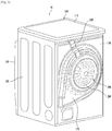
FIG. 1 is a cross-sectional diagram of a dryer according to one embodiment of the present disclosure. -
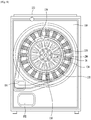
FIG. 2 is a diagram showing a rear view of a dryer according to one embodiment of the present disclosure. -
FIG. 3 is an enlarged diagram of a drive unit of a dryer according to one embodiment of the present disclosure. -
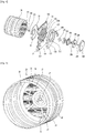
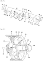
FIG. 4 is an exploded diagram showing components of a drum, rear case and drive unit of a dryer according to one embodiment of the present disclosure. -
FIG. 5 is a diagram showing a front view of a drum according to one embodiment of the present disclosure. -
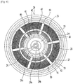
FIG. 6 is a diagram showing a rear view of a drum according to one embodiment of the present disclosure. -
FIG. 7 is a diagram showing an air inflow structure in a drive unit of a dryer according to one embodiment of the present disclosure. -
FIG. 8 is a diagram showing an external view of a rear case of a dryer according to one embodiment of the present disclosure. -
FIG. 9 is a diagram showing an internal view of a rear case of a dryer according to one embodiment of the present disclosure. -
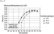
FIG. 10 is a graph showing the necessity and deceleration rate of a decelerator in a dryer according to an embodiment of the present disclosure. -
FIG. 11 is an exploded diagram of components of a decelerator of a dryer according to one embodiment of the present disclosure. -
FIG. 12 is a diagram showing the components engaged for a first-stage shift of a decelerator. -
FIG. 13 is a diagram showing the components engaged for a second-stage shift of a decelerator. -
FIG. 14 is a graph of comparison of speed standard deviation depending on a position of a cross section of a drum between a dryer according to one embodiment of the present disclosure and a related art dryer. - Reference will now be made in detail to the preferred embodiments of the present disclosure, examples of which are illustrated in the accompanying drawings.
- First of all, major components of a dryer will be described with reference to
FIG. 1 andFIG. 2 . In the present specification, for clarity of description, a direction of adoor 140 of a dryer shown inFIG. 1 may be defined as a front direction and a direction of adrive unit 200 may be defined as a rear direction. - A
dryer 10 includes acase drum 20 provided within the case. Drying objects may be placed within thedrum 20. In case of a laundry dryer, laundry may be put in thedrum 20 and then dried. - The case may include a
top case 100 forming a top surface of the dryer, afront case 120 forming a front surface arear case 130 forming a rear surface and alateral case 150 forming a lateral surface. In addition, the case may include adryer base 155 forming a bottom part of the dryer. The cabinet forms an inner surface, and various components including thedrum 20 are received in the inner space. - The
top case 100, thefront case 120, therear case 130, thelateral case 150 and the base 155 are structurally coupled together. Hence, each of the cases and the base forms a support structure supportive of an outer shape of the dryer as well as an exterior in a prescribed direction of the dryer. - A
door 140 is provided to the front case. After thedoor 140 has been open, laundry may be put into the drum. - The
drum 20 may be rotatably provided with reference to a horizontal axis parallel to a ground surface. - The
drum 20 is formed in a cylindrical shape, and a front side of thedrum 20 is open to put laundry in the drum. - A plurality of
lifters 30 may be provided on an inner wall of thedrum 20. Thelifter 30 may be provided in a manner of extending in front-rear direction. Thelifter 30 may be configured to be rotated together with the drum as an integral part. As thedrum 20 is rotated, thelifter 30 lifts laundry. If the drum is further rotated, the laundry leaves thelifter 30 and then falls down by gravity. Owing to the rotation of thedrum 20, the shaking of the laundry may be further smoothened and activated within thedrum 20 by thelifter 30. Therefore, the laundry may be evenly exposed to hot air. - According to the present embodiment, a
drive unit 200 configured to drive thedrum 20 is located in rear of thedrum 20. Thedrive unit 200 includes amotor 260 including arotor 270 and astator 280. A rotation axis of therotor 270 and a rotation axis of the drum may be formed coaxially. Namely, thedrum 20 and therotor 270 are rotated with the same center of rotation. Hence, the dryer according to the present embodiment may be referred to as a Direct Drive (DD) dryer. - To transfer the power of the
rotor 270 to thedrum 20, adrum shaft 210 is provided to thedrum 20. Thedrum shaft 210 is connected to the center of arear wall 22 of thedrum 20. Hence, as thedrum shaft 210 is rotated, thedrum 20 is rotated with thedrum shaft 210 as an integral part. - To support a front side of the
drum 20, afront supporter 160 may be provided. Thefront supporter 160 may be coupled to a rear side of thefront case 120 or formed as a portion of thefront case 120. - In the belt type dryer of the related art, an opening is formed in the rear side of a drum as well as in the front side of the drum and the drum substantially includes a cylindrical sidewall having open front and rear sides only. And, a rear supporter is provided to the rear opening of the drum. Namely, the drum is supported by the rear supporter while the rear opening of the drum is closed. As the rear supporter is a fixed component, the sidewall of the drum is rotated only by a belt.
- Yet, according to the present embodiment, the
drum 20 includes therear wall 22 as well as thesidewall 21 of the cylindrical type, and thesidewall 21 and therear wall 22 are rotated as an integral part. Therefore, the drum rear support structure of the present embodiment is different from the belt type dryer of the related art. - Regarding the drum of the present embodiment, unlike the drum of the related art dryer, the
sidewall 21 and therear wall 22 of thedrum 20 are rotated as an integral part. The drum of the present embodiment may be similar to a drum of a washer. Yet, since the drum of the present embodiment is not provided for washing, through-holes for air or water entrance are not formed on the sidewall of the drum. Instead, a plurality of perforated holes or a perforated portion for allowing air communication but excluding entrance of laundry may be formed in therear wall 22. This will be described later. - The rear side of the
drum 20 may be rotatably supported by thedrum shaft 210. Particularly, as thedrum shaft 210 is rotatably supported to therear case 130, the rear side of the drum may be eventually regarded as rotatably supported to therear case 130. Therear case 130 is configured to form a support structure of the whole dryer. Hence, the rear side of thedrum 20 may be supported rotatably and solidly through therear case 130 that is the support structure of the dryer. - As shown in
FIG. 3 , thedrum shaft 210 is extended in the rear direction from the center of therear wall 22 of thedrum 20. And, thedrive unit 200 and thepower transfer unit rear wall 22. Thepower transfer unit drum shaft 210, and thedrive unit 200 includes themotor 260 and thepower transfer unit - The
power transfer unit drum 20 and arotor 270 of themotor 260, thereby transferring a drive force of the rotor to the drum. Hence, thedrive unit 200 including thepower transfer unit drum 200. - The
motor 260 may include astator 280 and therotor 270 rotatably provided outside in a radial direction of thestator 280. Thus, themotor 260 may be referred to as an outer rotor type motor. Such an outer motor type motor is popularly used for a Direct Drive (DD) washer. Yet, as described above, since the related art dryer has difficulty in implementing a DD dryer, it is difficult to apply an outer rotor type motor to the related art dryer. - According to the present embodiment, the
stator 280 is preferably provided to an outside of therear case 130. Particularly, thestator 280 is preferably provided as fixed to the outside of therear case 130. Therear case 130 is configured to form an appearance of the dryer on the rear side of thedryer 10 and also form an inner space of the dryer. Hence, therear case 130 is configured to be fixed. Thus, as thestator 280 is fixed to the outside of therear case 130, it can be fixed solidly. - As the
motor 260 is provided to the outside of therear case 130, a space between an inner side of therear case 130 and the drumrear wall 22 may be provided enough to avoid a rotation interference of the drum. In addition, as themotor 260 is provided outside therear case 130, the manufacturing is considerably facilitated. - The
stator 280 may be provided so as to be spaced apart from a rear surface of therear case 130. Namely, it is preferable that thestator 280 is not coupled to contact with therear case 130 in direct. Aconnector 250 is provided between therear case 130 and thestator 280. Thestator 280 may be coupled to therear case 130 through theconnector 250. - A
decelerator 230 may be provided to an inside of theconnector 250, and more particularly, to ahollow part 250a located at a radial inside of the connector. Namely, thedecelerator 230 may be inserted in theconnector 250. Hence, it is able to minimize that a front-rear space of thedrive unit 200 or thepower transfer unit decelerator 230. - The
decelerator 230 may be located between therotor 270 and thedrum 20. Thedecelerator 230 may be configured to transform and transfer the drive force of therotor 270 to thedrum 20. Particularly, thedecelerator 240 may be configured to transform high RPM and low torque of therotor 270 into low RPM and high torque of thedrum 20. - The
drum shaft 210 coupled to thedrum 20 is located in front of thedecelerator 230, and arotor shaft 220 coupled to therotor 270 is located in rear of thedecelerator 230. Therotor shaft 220 is rotated with the rotor as an integral part, and thedrum shaft 210 is rotated with thedrum 20 as an integral part. Hence, thedecelerator 230 may configure the power transfer unit that transforms and transfers the power of the rotor shaft to the drum shaft. To secure efficiency and facilitation of such power transfer, it is preferable that thedrum shaft 210 and therotor shaft 220 are formed coaxially. - The
decelerator 230 may be installed in therear case 130. Thedecelerator 230 may be installed in a manner of directly contacting with the rear surface of therear case 130. Theconnector 250 is provided to a radial outside of thedecelerator 230, and thestator 280 may be installed in therear case 130 through theconnector 250. - The
rotor 270 rotates on the radial outside of thestator 280, and is substantially configured in a manner of being further extended in a front direction from the radial outside of the stator toward the rear case. Hence, securing a front-rear spaced distance between therear case 130 and thestator 280 through theconnector 250 may be necessary to secure a rotation space of therotor 270. - In addition, the
decelerator 230 is located in a manner of being inserted in theconnector 250. Therefore, a front-rear with of thedrive unit 200 by thedecelerator 230 and themotor 260 may be formed to be very compact, whereby the external width extension of therear case 130 can be minimized. - In some implementations, the
drive unit 200 including thepower transfer unit - According to the present embodiment, since the
motor 260 and thedecelerator 230 are located in rear of therear case 130, such components may be externally exposed and need protection. To this end, as shown inFIG. 4 , adrive unit cover 180 may be provided to cover the drive unit in rear of thedryer 10. - Among the components configuring the
drive unit 200, the largest component in a radial direction may be therotor 270. Hence, except therotor 270, all the components configuring thedrive unit 200 are located within a radial inside of therotor 270. Hence, it is necessary for thedrive unit cover 180 to fully cover therotor 270 only. Namely, thedrive unit cover 180 may be formed in a circular dish having an outer diameter slightly greater than that of therotor 270. - The
drive unit cover 180 may be coupled to therear case 130 in the rear direction of the rear case. Alternatively, thedrive unit cover 180 may be coupled to aflow path duct 170 described later. Thedrive unit cover 180 and theflow path duct 170 are just located in rear of therear case 130 but may not be the components that configure the support structure of the dryer. Therefore, although thedrive unit cover 180 and theflow path duct 170 are removed, the support structure of the dryer may not change. Yet, according to the present embodiment, in a manner that thedrive unit 200 and the air flow path are partially extended to a rear outside of therear case 130 instead of an inside of thecase 10, thedrive unit cover 180 and theflow path duct 170 may be provided. - According to the present embodiment, a rear air inflow structure for providing air to the
drum 20 from an outside of therear case 130 may be provided. Particularly, as theflow path duct 170 is installed in therear case 130, air may be supplied into thedrum 20 through theflow path duct 170. - The
flow path duct 170 is mounted on the rear surface of therear case 130, thereby forming aspace 171 inside to enable air to flow therein. Theflow path duct 170 may be formed on a radial outside of thedrive unit 200. Namely, theflow path duct 170 may be configured to enclose thedrive unit 200. - Therefore, the
air flow space 171 in theflow path duct 170, themotor 260 and thedecelerator 230 may be structurally divided or separated outside therear case 130. Thus, air flow may be performed smoothly, and hot or humid air may be prevented from entering themotor 260 or thedecelerator 230. - An air communication structure among the
flow path duct 170, therear case 130 and thedrum 20 will be described in detail later. - The
motor 260 is located on a rear outside of therear case 130. And, themotor 260 is enclosed by theflow path duct 170 on the rear outside of therear case 130. Hence, a wire or signal line extended from an inside of thecase 100 has difficulty in being connected to themotor 260. - According to the present embodiment, a wire or signal line passing through the
rear case 130 may be extended to a radial inside from a radial outside of theflow path duct 170 and then connected to themotor 260. In this case, the wire or signal line may be exposed externally. To prevent such exposure, awire cover 190 may be provided. - The connection and position relation among the drum
rear wall 22, therear case 130 and thedrive unit 200 will be described in detail with reference toFIG. 3 andFIG. 4 as follows.FIG. 3 is an enlarged cross-sectional diagram of the rear part of the dryer shown inFIG. 1 , andFIG. 4 is an exploded perspective diagram of the drum, rear case and drive unit. - The
rear case 130 is located in rear of the drumrear wall 22. As the drumrear wall 22 is rotatably configured, it is located in a manner of being spaced apart from therear case 130. - The
motor 260 is provided to an outside of therear case 130. Thestator 280 of the motor is located in a manner of being spaced apart from the rear surface of the rear case toward a rear direction by theconnector 250 and fixed to therear case 130. - To transfer a drive force of the
rotor 270 of the motor to thedrum 20, thepower transfer unit power transfer unit drum shaft 210, thedecelerator 230 and therotor shaft 220. - To transfer a drive force of the
rotor 270, therotor 270 is coupled to therotor shaft 220. Therotor shaft 220 forms the same axis with a rotation axis of a rotor and rotates with the rotor as an integral part. Hence, to secure the coupling rigidity and the power transfer reliability, acoupler 296 may be provided. Thecoupler 296 may be referred to as arotor coupler 296. - The
rotor coupler 296 may be coupled to an inner surface of the rotor through a plurality of bolts. Therotor shaft 220 may pass through therotor coupler 296 and be coupled to therotor 270 by astud 294. To rigidify the coupling by the stud, awasher 295 may be inserted between thestud 294 and therotor 270. - Regarding the
stud 294, a female screw may be formed at the center of therotor shaft 220 so as to be coupled with the stud. - In addition, the
rotor shaft 220 may be coupled to therotor coupler 296 by serration. A serration may be formed on an outer circumference of therotor shaft 220 and a serration may be formed on the rotor coupler through which the rotor shaft passes. Hence, a drive force of the rotor may be solidly transferred to therotor shaft 220. - A drive force of the
rotor shaft 220 is transformed through thedecelerator 230 and then transferred to thedrum shaft 210. Thedrum shaft 210 may have the coupling structure identical or similar to that of therotor shaft 220 and be coupled to the drumrear wall 22. - Namely, a
stud 291, awasher 292 and adrum coupler 293 may be provided. Shapes and structures of them may be identical or similar to those of thestud 294,washer 295 androtor coupler 296 for the coupling of therotor shaft 220. - The
stud 291 may pass through a studperforated hole 29a from an inside of the drum to an outside (i.e., from a front side to a rear side) and be then coupled to thedrum shaft 210. On the other hand, thestud 294 may pass through a stud perforated hole from an inside of the rotor to an outside of the rotor (i.e., from a rear side to a front side) and be then coupled to therotor shaft 220. - The
rotor shaft 220 rotates with therotor 270 as an integral part, and thedrum shaft 210 rotates with thedrum 20 as an integral part. Hence, thedecelerator 230 may be referred to as a device for performing power transform between therotor shaft 220 and thedrum shaft 210. - The
decelerator 230 includes a transformingdevice 240 provided within the housing. The transforming device may include various gears. Therotor shaft 220 and thedrum shaft 210 may be extended into thehousing 231 and then connected to the transforming device. Therotor shaft 220 and thedrum shaft 210 may be parts of thedecelerator 230 or partial configuration of the transforming device. - A drum shaft perforated
hole 232 is provided to a front side of thehousing 231 so that thedrum shaft 210 can pass through the drum shaft perforatedhole 232. The drum shaft perforatedhole 232 may be configured in a manner of being extended in the front direction. Namely, it may be configured to form a prescribed front straight-line distance. The drum shaft perforatedhole 232 may pass through a shaftperforated hole 130a formed in therear case 130. - The shaft perforated
hole 130a is formed to enable thedrum shaft 210 to be extended from therear wall 22 of thedrum 20 to thedecelerator 230 in a manner of passing through the rear case q130. Here, it is not preferable that thedrum shaft 210 is rotatably supported through the shaft perforatedhole 130a. Namely, since therear case 130 is formed using a plate such as a thin steel sheet, if a bearing support structure is formed in a perforated hole formed in a plate, it is not easy and preferable. - Therefore, it is preferable that the shaft perforated
hole 130a is formed to have a diameter so that the drum shaft perforatedhole 232 of thedecelerator housing 231 as well as thedrum shaft 210 can pass through the shaft perforatedhole 130a. - The
decelerator housing 231 may be fixed and coupled to the rear side of therear case 130. The drum shaft perforatedhole 232 of thedecelerator housing 231 may be further extended in the front direction by passing through the shaft perforatedhole 130a. - A bearing 234 may be provided within the drum shaft perforated
hole 232. Thedrum shaft 210 may be inserted into thebearing 234. Therefore, thedrum shaft 210 may be rotatably supported to the housing through thebearing 234. As thehousing 231 is fixed to therear case 130, thedrum shaft 210 may be rotatably provided to therear case 130 through the housing. - In addition, the
decelerator housing 231 may be fixed and coupled to theconnector 250. Thedecelerator housing 231 may be coupled in a manner of being fixed to an inside of theconnector 250 by stamping. Theconnector 250 may be fixed to the rear case in the rear direction of the rear case in a manner of enclosing thedecelerator housing 231. - Therefore, the
decelerator 230 may be solidly fixed to therear case 30 through theconnector 250. This is because a radius of a part (e.g., a coupling part through a bolt or stud) for coupling theconnector 250 to therear case 130 is greater than that of thedecelerator housing 231. - As described above, the
motor 260 may include an outer rotor type motor. Therefore, therotor 260 rotates on a radial outside of thestator 280. Based on such a structure, ahollow part 280a may be formed in a radial inside of thestator 280. - A portion of the
connector 250 may be inserted in thehollow part 280a. Through this, the front-rear length increase of thedrive unit 200 may be prevented and thestator 280 may be solidly coupled to theconnector 250. - By the
decelerator 230, a front-rear length for the connection of a rotation axis (i.e., a rotation axis including a drum shaft, a middle shaft described later, and a rotor shaft) between therotor 270 and thedrum 20 may be increased. Therefore, it is important to secure a rotatable support point of the rotation axis. However, it is not preferable that an overall length of a rotation axis is increased for the support point securing. - A portion of the rear side of the
decelerator housing 231 is preferably inserted in thehollow part 280a of thestator 280. - A rotor shaft perforated
hole 233, through which therotor shaft 220 passes, is formed in the rear side of the decelerator housing. The rotor shaft perforatedhole 233 may be formed in a manner of extending in a rear direction. Namely, it may be provided to form a prescribed rear straight-line distance. The rotor shaft perforatedhole 233 is preferably inserted in thehollow part 280a of thestator 280. - A bearing 236 may be provided within the rotor shaft perforated
hole 233. Therotor shaft 220 may be inserted in thebearing 236. Hence, therotor shaft 220 may be rotatably supported to thehousing 231 through thebearing 236. As thehousing 231 is fixed to therear case 130, and more particularly, may be fixed through the connector, therotor shaft 220 may be regarded as provided rotatably to therear case 130 as well. - As described above, the bearing support point of the
drum shaft 210 is substantially located in a space between the drumrear wall 22 and the front side of therear case 130. In addition, the bearing support point of therotor shaft 220 is substantially located within thestator 280, i.e., thehollow part 280a. Therefore, the bearing support point of the overall rotation axis can be secured smoothly, thereby preventing an overall length of the rotation axis from being increased. - In addition, since the
bearings decelerator housing 231 in advance, the manufacturing is further facilitated. - The
decelerator 230 may include amiddle shaft 241. The transformingdevice 240 of the decelerator may include themiddle shaft 241. Themiddle shaft 241 is theshaft 241 for connecting therotor shaft 220 and thedrum shaft 210 coaxially and is configured to be rotated independently from thedrum shaft 210 or therotor shaft 220. - The
middle shaft 241 is inserted in the center of each of therotor shaft 220 and thedrum shaft 210, whereby those shafts are configured coaxially. A bearing is 235 provided to an outside of themiddle shaft 241 and an inside of thedrum shaft 210. Through thebearing 235, the middle shaft and the drum shaft may be rotated independently. Abearing 237 is provided to an outside of themiddle shaft 241 and an inside of therotor shaft 220. Through thebearing 237, the middle shaft and the rotor shaft may be rotated independently. - By the aforementioned structures of the
drum 20, therear case 130, the power transfer unit and the drive unit, the assembly may be further facilitated. - First of all, the
decelerator 230 and theconnector 250 are coupled together. Theconnector 250 is coupled to therear case 130. After thestator 280 has been coupled to theconnector 250, theconnector 250 may be coupled to therear case 130. Thereafter, the stator is coupled to theconnector 250. As therotor shaft 220 is semi-coupled by being inserted in the center of therotor 260. Likewise, thedrum shaft 210 may be semi-coupled by being inserted in the center of the drumrear wall 22. - Inside the drum, through the
stud 291, the drum rear wall and thedrum shaft 210 are coupled together. On the outer rear side of therotor 270, through thestud 294, therotor 270 and therotor shaft 220 are coupled together. - Through such a sequence, the coupling of the
drum 20, therear case 130, thepower transfer unit motor 260 may be facilitated. Thereafter, theflow path duct 170 may be coupled to therear case 130 in the rear direction of the rear case, and thedrive unit cover 180 may be coupled to theflow path duct 270 so as to protect thedrive unit 200. Wires or signal lines exposed after having been connected to themotor 260 may be protected by thewire cover 190. One end of thewire cover 190 may be coupled to therear case 130 on the radial outside of the flow path duct, and the other end may be coupled to the flow path duct or therear case 130 on the radial inside of theflow path 170. Alternatively, after thewire cover 190 has been coupled, thedrive unit cover 180 may be coupled. - In the following, with reference to
FIG. 5 andFIG. 6 , thedrum 20 applicable to the present embodiment will be described in detail. -
FIG. 5 is a perspective diagram of a front side of a drum, andFIG. 6 is a front diagram of a rear side of the drum. - The
drum 20 may include thesidewall 21 and therea wall 22 in a manner that a front side is open. The drum may be configured in a cylindrical shape of which rear side is blocked by therear wall 22. Here, the 'blocked' means that entrance of laundry is impossible and that air communication is possible. - An
installation area 23 is formed at a central portion of therear wall 22. Theinstallation area 23 may include an area in which thedrum shaft 210 is installed and indicate an area that confronts thedecelerator 230. Anair intake area 24 may be formed on a radial outside of theinstallation area 23. A rearwall rim area 25 is formed on a radial outside of theair intake area 24 and may be connected to thesidewall 21. - Assuming that the
rear wall 22 has a circular shape, theinstallation area 23 may be formed to exclude the air communication for the installation of the drum shaft at the central portion, and theair intake area 24 may be formed on a radial outside of theinstallation area 23 to enable air to pass therethrough. - To enable air to communicate, a plurality of
holes 26 are formed in theair intake area 24. Particularly, theair intake area 24 of a mesh type is formed. If theair intake area 24 becomes wider, air may be supplied with the drum more evenly, whereby drying efficiency can be raised. A diameter of thehole 26 is very small. This is to prevent laundry from entering thehole 26 and being damaged. Therefore, the number of theholes 26 will be very high to enable air to be supplied into the drum smoothly. - However, the rigidity of the
rea wall 22 may become vulnerable by theholes 26. To reinforce the rigidity of therear wall 22 from theair intake area 24, a plurality ofradial bridges 27 and acircumferential bridge 28 may be included. The radial bridges 27 may be provided to divide theair intake area 24 along a circumferential direction, and thecircumferential bridge 28 may be provided to divide theair intake area 24 into a radial inside and a radial outside. - The
radial bridge 27 may be extended from the installation are 23 to the rearwall rim area 25 via theair intake area 24. Theradial bridge 27 may be connected to thecircumferential bridge 28. - It is preferable that the
holes 26 are not formed in theradial bridges 27 and thecircumferential bridge 28. Therefore, as a support structure supportive of theair intake area 24 of the mesh type attributed to a plurality of theholes 26, the radial bridges 27 and thecircumferential bridge 28 may be formed. Preferably, to reinforce self-rigidity, the radial bridges 27 and thecircumferential bridge 28 may be formed convex in front or rear direction. - Preferably, the
holes 26 are not formed in the rearwall rim area 25 as well. As the rearwall rim area 25 is connected to thesidewall 21, it is necessary to prevent the rigidity of the rearwall rim area 25 from being weakened. Moreover, in case that air flows in the rearwall rim area 25, the air may be supplied to laundry closely attached to an inner wall of the drum or a place in which laundry does not exist. Therefore, to raise the drying efficiency, it is preferable that air supply is focused not on the rearwall rim area 25 but on theair intake area 24. - A
stud hole 29a may be formed at the center of theinstallation area 29 of the central portion of the drumrear wall 22. Awasher seat part 29c may be formed on a radial outside that encloses thestud hole 29. A plurality ofbolt fastening parts 29b may be formed in a radial outside of thewasher seat part 29. Here, a stud, bolt or screw in the present embodiment may be named for convenience according to a relative size of a fastening means. Therefore, the fastening means may be non-limited by the specific names. - The
installation area 29 may be the area that is fastened with thedrum shaft 210. To fasten thedrum shaft 210 to thedrum 20 rigidly and secure reliability of power transfer, a coupler is provided. This may be referred to as a drum coupler 293 (seeFIG. 3 ). - It is not preferable that hot air substantially flows into the drum through the central portion of the drum rear wall. Therefore, it is preferable that the
installation area 29 is more extended to a further radial outside of the drum coupler. -
FIG. 6 shows that agasket rear wall 22. Thegasket rear wall 22 and therear case 130. Namely, air flowing in from an outside of therear case 130 flows into the drum through theair intake area 24 by the sealing provided by the gasket between the drumrear wall 22 and therear case 130. - The position, structure and function of the
gasket FIG. 7. FIG. 7 is a cross-sectional diagram of the drum, drive unit and flow path duct in a gasket part. - The
gasket inner gasket 40 of a radial inside and anouter gasket 50 of a radial outside. Theinner gasket 40 partitions theinstallation area 29 and theair intake area 24 of the drum. Therefore, it is able to prevent hot air from leaking in an installation area direction (toward a radial inside) of the drum from an outside of the drum. Theouter gasket 50 partitions theair intake area 24 and the rearwall rim area 25 of the drum. Therefore, it is able to prevent hot air from leaking into the rearwall rim area 25 of the drum from an outside of the drum. - The
inner gasket 40 includes a fixingpart 41 and anextension part 42, and afastening part 43 may be formed in the fixingpart 41. Theinner gasket 40 may be mounted on an inner surface of the rear case through the fixingpart 41 and thefastening part 43, and theextension part 42 may be formed in a manner of being extended from the fixingpart 41 in a direction of the drumrear wall 22. Theextension part 42 is configured to contact with the drum rear wall, whereby sealing can be performed. Theextension part 42 may be slantly extended toward an inside from a radial outside. Namely, theextension part 42 may be located on a radial inside of the fixingpart 41. - Likewise, the
outer gasket 50 includes a fixingpart 51 and anextension part 52, and afastening part 53 may be formed in the fixingpart 51. Theouter gasket 50 may be mounted on an inner surface of the rear case through the fixingpart 51 and thefastening part 53, and theextension part 52 may be formed in a manner of being extended from the fixingpart 51 in a direction of the drumrear wall 22. Theextension part 52 is configured to contact with the drum rear wall, whereby sealing can be performed. Theextension part 52 may be slantly extended toward an outside from a radial inside. Namely, theextension part 52 may be located on a radial outside of the fixingpart 51. - The
extension part 42/52 of the inner/outer gasket 40/50 may be slantly extended from the fixingpart 41/51 toward the drum rear wall. Through this, air sealing may be performed while the frictional force between the rotating drum and the end of theextension part 42/52. - Of course, unlike the above description, the
gasket rear case 130 but in thedrum 20. Yet, it will be preferable that the gasket is installed not in the rotatably-configureddrum 20 but in the fixedrear case 130. Through this, as the sealing point may be formed not in the upstream of an air flow path but in the downstream thereof, it becomes more advantageous in aspect of sealing as well as manufacturing facilitation. - Meanwhile, as shown in
FIG. 7 , the power transfer unit may be placed in a hermetically sealed space. For example, the motor including thestator 280 and therotor 260 and the decelerator may be located within a space enclosed by therear case 130, theflow path duct 170 and thedrive unit cover 180. - As the drum is driven, heat is generated from the decelerator and the motor, and more particularly, from the stator. If such a heat problem is resolved, it is very advantageous in securing performance. Therefore, it is preferable that a component for heat radiation or cooling is added.
- Instead of adding such a component as a separate cooling fan, cooling performance may be secured using natural convection or convection through rotation of a rotor.
- A plurality of
openings 260a may be formed in therotor 260. As the rotor rotates, air may flow into the rotor from an outside of the rotor. The inflow air may flow toward thestator 280. - Meanwhile, the air flowing into the
rotor 260 preferably includes external air. To this end, anopening 180a may be provided to thedrive unit cover 180. A plurality of theopenings 180a may be provided. - The air flowing in through the
opening 180a of thedrive unit cover 180 cools down the stator within the rotor through theopening 260a of the rotor. Here, if the air having cooled down the rotor is discharged externally, effective air circulation or flow can be generated. Therefore, adischarge part 180b for discharging air externally is preferably formed in thedrive unit cover 180. - By such a structure, as shown in
FIG. 7 , an air flow is generated, whereby effective cooling can be performed. - Here, it is preferable that the
opening 260a of the rotor and theopening 180a of thedrive unit cover 180 are located to confront each other. Through this, air flow resistance can be minimized. Meanwhile, in case that air flows in from an outside, it is not preferable that an inflow pressure becomes excessively high. Therefore, the number and total size of theopenings 180a may be preferably greater than those of the rotor, respectively. - In addition, to perform the inflow and discharge of air smoothly, a position of an inflow part of air is preferably different from that of a discharge part of air. Namely, the position of the discharge part is located at a radial outside of the position of the inflow part.
- Accordingly, by forming the openings for the air inflow and discharge in the
drive unit cover 180 with ease, effective cooling of the motor and decelerator can be performed. - With reference to
FIG. 8 andFIG. 9 , an air flow path of a dryer according to one embodiment of the present disclosure is described in detail. - An
outlet 131 for discharging air from a dryer inside externally may be formed in therear case 130. Aninlet 135 for the air discharged through theoutlet 131 to flow into the dryer may be formed in therear case 130. Theoutlet 131 is a single outlet but a plurality of theinlets 135 may be formed. - The inlet may be formed in an
air supply area 134 of therear case 130, and theair supply area 134 may be formed on a radial outside of aninstallation area 136. Theair supply area 134 may be configured to enclose theinstallation area 136. - The
outlet 131 may be formed in the air intake area of therear case 130. The air intake area may be provided to a radial outside of theair supply area 134. As theoutlet 131 may be configured as a single outlet, the outlet may be regarded as the air intake area. - The air having flown into the
flow path duct 170 via theoutlet 135 flows into the dryer through theinlet 135. Particularly, a flow path passing through theinlet 135 may enter the drum in a manner of passing through a space between the drumrear wall 22 sealed by thegasket - To reduce resistance of a flow of air that flows in via the
inlet 135, it is preferable that a size of theinlet 135 is greater than that of ahole 26 through which air flows into the drum. As shown in the drawing, the number of theholes 26 of the drum projected onto thesingle inlet 135 may be equal to or greater than 10. - The area in which the
holes 26 of the drum are formed is formed continuously along a circumferential direction except aradial rib 27. On the other hand, theinlet 135 and theinlet 135 may be configured in a manner of being spaced apart from each other along the circumferential direction. A size of a portion of theair inflow area 134, in which theinlet 135 is formed, may be similar to that of a portion in which the inlet is not formed. - Moreover, it is preferable that a radial direction width of the
inlet 135 is preferably smaller than a radial width of theair intake area 24 of the drum. Namely, it is preferable that a size for sucking air from the drum is greater than a size for supplying air to the drum from the rear case. Through this, air inflow may be performed more smoothly and air can be evenly flow into the drum. - The
flow path duct 170 may be configured to cover both of theair intake area 131 and theair supply area 134 of the rear case except the installation area of the rear case. Therefore, the air having flown into theflow path duct 170 via the air intake are 131 may diverge into both sides of the installation area and then flow along an installation area circumference, thereby being discharged from the flow path duct through theinlet 134. - The air discharged through the
inlet 134 flows into the drum through a plurality ofholes 29 formed in theair intake area 24 formed in the drumrear wall 22. The air having flown into the drum is discharged to a drum front side, passes through aheat pump 300 and afan 179, and is then discharged out of the dryerrear case 130 through theoutlet 131 of the rear case. - In some implementations, the
heat pump 300 may be substituted with a heating part (not shown). Namely, a configuration for condensing moisture in air may be omitted. So to speak, air outside the dryer is made to flow into the dryer and then heated, - Through such a structure, air can be dried in a manner of circulating in the dryer according to the present embodiment. A
fan 179 for generating circulation flow of air, aheat pump 300 as an exemplary configuration for heating and condensing air, aflow path duct 170 forming a flow path of air, a connectingduct 179 forming the flow path of the air and the like may be included. - Meanwhile, a
fan mount part 132 projected in rear direction may be provided to therear case 130. Theoutlet 131 may be formed in thefan mount part 132. A wire draw-outhole 133 may be formed in a top portion of therear case 130. - The
flow path duct 170 may include aninner coupling part 172 and anouter coupling part 171. Theinner coupling part 172 may be coupled to the rear case between the mount area of the rear case and the air supply area. Theouter coupling part 171 may be coupled to the rear case in a manner of enclosing both of the air supply area and the air intake area of the rear case. Anextension part 173 is formed between theouter coupling part 171 and theinner coupling part 172 so as to form anair flow space 171. - The
extension part 173 may be configured in a manner of being convex in rear of therear case 130. Hence, a wire extended to a rear case outside through the wire draw-outhole 133 needs to be connected to the motor located at a radial inside of theinner coupling part 172 of theflow path duct 170 by crossing theextension part 173. Hence, awire cover 133 for protecting the crossing wire crosses theextension part 173 as well. The front-rear width of the dryer may be increased by thewire cover 133. Therefore, aseat part 173 recessed in front direction is preferably formed at a prescribed portion of theextension part 173 so that the wire cover is seated on theseat part 173. - A wire coupling area or a wire cover coupling area 137 may be formed between the
air supply area 134 and theinstallation area 136 of therear case 130. The wire coupling area 137 may include an area formed in a manner that a prescribed portion of theinstallation area 136 is extended to a radial outside. Hence, a radial width of theinlet 135 formed in the radial outside of the wire coupling area may be decreased by the wire coupling area 137. - A wire coupling area may be formed in the flow path duct to correspond to the wire coupling area of the rear case. Through the wire coupling area, one end of the
wire cover 190 may be fixed and coupled thereto. - As described above, the
decelerator 230 is preferably included in the dryer according to one embodiment of the present disclosure. In the following, why the decelerator is required for one embodiment of the present disclosure and what is an optimal deceleration ratio will be described with reference toFIG. 10 . - To facilitate the torque and RPM control of a motor, an outer rotor type motor having a permanent magnet provided to a rotor is popularly used for a Direct Drive type device. In order to apply such an outer rotor type motor to the present embodiment, it is necessary to consider efficiency of a motor.
FIG. 10 shows efficiency of a motor according to a current phase angle in case of using a motor of 269-W power consumption. - As shown in the drawing, it is observed that efficiency of an outer rotor type motor is high in a high-speed drive range, e.g., 600 ∼ 750 RPM range. Yet, in a low sped drive at about 50 RPM that is a general drive RPM of a dryer drum, efficiency is noticeably decreased or a drum is not rotated due to the insufficient torque. Namely, there may occur a case that it is impossible to drive a drum. Thus, there may be a demand for a decelerator capable of driving a drum at about 50 RPM while driving a motor at the RPM having optimal efficiency. Therefore, according to the present embodiment, a decelerator having a deceleration ratio of 15:1 may be provided. Although an optimal deceleration ratio may be changed due to the difference of a motor and the difference of a drum drive RPM, it may be similar to 15:1 approximately.
- Generally, a decelerator that uses a planet gear is manufactured for the purpose of deceleration of a servo motor and the like and fastened to a front side of a motor. Hence, due the outer diameter limit of a decelerator by a motor, a safety rate is generally secured in a manner of increasing a thickness of a planet gear (e.g., an axial length of a gear).
- However, a decelerator of a dryer according to one embodiment of the present disclosure may require a compact design for a height (i.e., an axial length) of the decelerator rather than an outer diameter thereof. Namely, since a motor of the present embodiment is a motor of an outer rotor type, an outer diameter of a decelerator may be set to approach an outer diameter of a rotor as close as possible.
- To implement a high deceleration ratio (e.g., 15:1), a decelerator of a 2-stage planet gear type may be applicable. A decelerator of a 1-stage planet gear type is normally used at a deceleration ratio of about 9:1. If a deceleration ratio of about 15:1 is implemented in a decelerator of a 1-stage planetary type, the number of planet gears becomes two according to the geometrical feature of implementing the deceleration mechanism. Therefore, stability becomes very low. According to the present embodiment, to implement a high deceleration ratio and secure stability, it is able to apply a decelerator of a 2-stage planet gear type that eventually performs 2-stage deceleration by performing deceleration through four planet gears in 1-stage deceleration.
- Meanwhile, in case of using a 2-stage gear, as thickness (i.e., axial length of decelerator) due to gears is increased, the demand for the compact and light-weight design is considerably rising. According to the present embodiment, a decelerator capable of 2-stage changing high-RPM low-torque into low RPM high-torque between a rotor and a drum can be provided. And, a decelerator capable of implementing compactness and lightweight in consideration of power transform features in a dryer can be provided.
- In 1-stage power transform, a thickness of a gear may be decreased in consideration of a feature that a torque of an input shaft (e.g., a rotor shaft in the present embodiment) is low. And, it is able to form a gear not through steel series materials but through engineering plastics such as Poly Oxy Methylene (POM) series materials. Therefore, by decreasing thickness and weight of a gear in proportion to strength of a gear, the compact and lightweight design will be possible.
- Yet, in 2-stage power transform, since a torque of an output shaft (e.g., a drum shaft in the present embodiment) is raised through 1-stage power transform, higher gear strength may be required. Therefore, in the 2-stage power transform, it will be preferable that a height of a gear is relatively increased and that a gear of steel materials is formed.
- In this respect, it may be difficult to implement a compact decelerator due to a thickness of a gear for power transform, and particularly, in 2-stage power transform,
- One embodiment of the present disclosure pays attention to gear strength improvement through an outer diameter increase of a gear instead of a thickness increase of a gear.
- By increasing a total outer diameter of a planet gear using the same deceleration ratio and the same-rated configurations, gear strength can be improved. Namely, if an outer diameter is increased in a gear having the same number of gear teeth, a size of a support part of the gear tooth is increased. So to speak, it is able to increase a size of a support part of a gear tooth in a manner of increasing a size of the gear tooth instead of increasing a thickness of a gear.
- Such gear strength securing is identically applicable to 2-stage power transform as well as 1-stage power transform. Hence, it is able to implement a decelerator that is very compact in front-rear direction in all of 1-stage gears and 2-stage gears having the same outer diameter. Particularly, since a decelerator of the present embodiment transforms power of an outer rotor type motor, an outer diameter increase of the decelerator can be allowed sufficiently. Specifically, it is possible to increase an outer diameter of a decelerator to correspond to an inner diameter of the
hollow part 250a of the connector that fixes the stator to the rear case. - In the following, a decelerator and deceleration principle according to one embodiment of the present disclosure will be described in detail with reference to
FIGs. 11 to 13 .FIG. 11 is an exploded perspective diagram of a decelerator,FIG. 12 shows a connection structure of decelerator components for 1-stage transform of power, andFIG. 13 shows a connection structure of decelerator components for 2-stage transform of power. - A
decelerator 230 includes ahousing 231, and the housing may include a front housing 231a and a rear housing 231b. Various components for a transforming device may be received in thehousing 231. Afastening part 231c may be provided to thehousing 231. The rear housing 231b may substantially receive the components for the transforming device therein, the front housing 231a may perform a cover function of covering the rear housing, and vice versa. - When the rear housing 231b substantially receives the components for the transforming device, the
fastening part 231c may be provided to the rear housing 231b. The rear housing 231b is inserted in thehollow part 250a of the connector and then coupled and fixed to theconnector 250 through thefastening part 231c. - A
perforated hole 233 of arotor shaft 220 is formed in a central portion of the rear housing 231b, and abearing 236 is provided within theperforated hole 233, whereby therotor shaft 220 is rotatably supported. - A
perforated hole 232 of adrum shaft 210 is formed in a central portion of the front housing 231a, and abearing 234 is provided within theperforated hole 232, whereby thedrum shaft 210 is rotatably supported. - An input RPM in 1-stage power transform may be regarded as a high RPM. Hence, the bearing 236 supporting the
rotor shaft 220 preferably includes a ball bearing. In addition, two ball bearings are preferably provided along therotor shaft 220. An output RPM in 2-stage power transform may be regarded as a low RPM. Hence, a bearing supporting thedrum shaft 210 preferably uses an oilless bearing. This is to secure reliability and save manufacturing costs. - Power of the
rotor 260 is directly transferred to therotor shaft 220. Therotor shaft 220 is solidly coupled to therotor 260 through therotor coupler 296, thewasher 295 and the stud 194. One side of therotor shaft 220 is coupled to the rotor, and the other side may configure afirst sun ear 221. Hence, therotor shaft 220 and thefirst sun gear 221 may be regarded as a single part or component, and may be the component formed of a single material. - The same
first planet gear 223 is located on a radial outside of thefirst sun gear 221, and the first sun gear and the first planet gear are engaged. If the first planet gear is provided to leave the same space in between along a circumferential direction of the first sun gear, four first planet gears may be provided for example. - The
first planet gear 223 is provided rotatably centering on aroller shaft 222, and theroller shaft 222 may be fixed to afirst carrier 243. For the front-rear position fixing of the first planet gear and the fixing of the roller shaft, afirst carrier supporter 224 may be provided. Hence, thefirst planet gear 223 may be rotatably provided to thefirst carrier 243. As thefirst planet gear 223 revolves around thefirst sun gear 221, thefirst carrier 243 rotates. - All the first planet gears 223 may be engaged in a manner of being inscribed in a
ring gear 244. - When a deceleration ratio in each step is set to 'a', if the
ring gear 244 is provided to be fixed within thedecelerator housing 231, 'a' has the value resulting from adding 1 to a value obtained from dividing the number of gear teeth of thering gear 244 by the number of teeth of the sun gear. - If a motor power of N RPM and T torque is inputted to the
rotor shaft 220, thefirst sun gear 221 has the same N RPM and the same T torque. - As the
rotor shaft 220 rotates, thefirst planet gear 223 and thefirst carrier 243 rotate. In doing so, thefirst carrier 243 has a deceleration ratio 'a', N/a RPM, and T*a torque. Hence, the power of therotor shaft 220 is 1-stage transformed through thefirst carrier 243. - The
first planet gear 223 is rotatably provided to one side (e.g., a rotor shaft side) of thefirst carrier 243. And, asecond sun gear 242 may be provided to the other side (e.g., a drum shaft side) of thesecond carrier 243. Thesecond carrier 243 and thesecond sun gear 242 may be configured as an integral part. Thus, thesecond carrier 243 and thesecond sun gear 242 rotate as an integral part. Therefore, thesecond sun gear 242 has a deceleration ratio 'a', N/a RPM, and T*a torque. - As the second sun gear rotates, the
second planet gear 213 and thesecond carrier 211 rotate. Thesecond planet gear 213 may be rotatably provided to thesecond carrier 211 through aroller shaft 212. For the front-rear position fixing of thesecond planet gear 213 and the fixing of theroller shaft 212, asecond carrier supporter 214 may be provided. - As the
second planet gear 213 revolves around thesecond sun gear 242, thesecond carrier 211 rotates. - In this case, the
second carrier 211 has a deceleration ratio 'a', N/a/a RPM, and T*a*a torque. - The
second carrier 211 may be coupled to thedrum shaft 210. Preferably, thesecond carrier 211 and thedrum shaft 210 may be provided as a single part or component. Hence, thedrum shaft 210 has N/a/a RPM and T*a*a torque. - As described above, a deceleration ratio of a decelerator in the present embodiment is 15:1. Hence, if each of a first-stage deceleration ratio and a second-stage deceleration ratio has the same value 'a', the value of 'a' may have the square root of 15, i.e., 3.871.
- Here, it is very effective to have a final deceleration ratio of the square root of 'a' by setting the second stage deceleration ratio to 'a' with the first stage deceleration ratio 'a'. This is because a ring gear used for the first stage deceleration and the second stage deceleration may be implemented as a single ring gear. Namely, a rear side of a fixed single ring gear may be engaged with the first planet gears and a front side of the single ring gear may be engaged with the second planet gears. Therefore, implementation of a decelerator can be very facilitated.
- In addition, there is an effect that radius sizes of planet gears and carriers can be set equally. Hence, it is able to implement a decelerator having a cylindrical shape and the same front-rear diameter. Of course, a fastening part structure for the fixed coupling of a decelerator is out of the question.
- The
drum shaft 210 may be solidly fixed to the drum rear wall through adrum shaft coupler 293, awasher 292 and astud 291. - Eventually, according to the present embodiment, there decelerator 230 is provided between the drum rear wall and the rotor inner wall, thereby transforming high-RPM and low-torque of the rotor into low-RPM and high-torque of the drum.
- Meanwhile, the
rotor shaft 220 and thedrum shaft 210 are spaced apart from each other in front-rear direction. Therotor shaft 220 and thedrum shaft 210 are configured to form a co-axis, and the co-axis needs to be maintained solidly. - To this end, a
middle shaft 241 may be provided. One side of the middle shaft may form a co-axis by being connected to therotor shaft 220, and the other side may form the co-axis by being connected to thedrum shaft 210. - The
middle shaft 241 may configure an integral part with thefirst carrier 243 and thesecond sun gear 242. Namely, they may include a single component or part. Hence, themiddle shaft 241 and thefirst carrier 243 may rotate as an integral part. This means that a rotation speed of the first carrier is different from a rotation speed of each of the rotor shaft and the drum shaft. - Therefore, a structure for supporting that the
middle shift 241, thedrum shaft 210 and therotor shaft 220 may rotate at different rotation speeds, respectively or rotate independently is necessary. Of course, such a support structure may include a structure for forming and maintaining a co-axis. - The
middle shaft 241 is positioned in a manner of being inserted in the center of thedrum shaft 210 and the center of therotor shaft 220. The middle shaft may be inserted in a hollow formed at prescribed portions of the drum and rotor shafts. Abearing 235 is provided between the drum shaft and the middle shaft. Likewise, abearing 237 may be provided between the rotor shaft and the middle shaft. - A thrust generated between the
rotor 260 and the drumrear wall 22 may be supported theaforementioned bearings oilless bearing 234 comes in contact with a circumference of the drum shaft and a lateral side of theball bearing 236 comes in contact with an annular ring (no reference number inFIG. 10 ) coupled to the shafts. Therefore, a frictional force due to the thrust in the drive unit or the power transfer unit can be minimized. - Meanwhile, a decelerator different from the above-described planet gear decelerator of one embodiment of the present disclosure may be applicable to a dryer according to one embodiment of the present disclosure. For example, a cyclo-decelerator is applicable.
- A cyclo-decelerator is a decelerator that uses a decelerating device having a cyclo-tooth shape. The cyclo-decelerator is a decelerator of which gear tooth shape forms a continuous curve of a cyclo-tooth shape to enable rolling contact. As an input shaft and an output shaft may form a co-axis, it is applicable to the present embodiment.
- In a dryer according to one embodiment of the present disclosure, uniform drying can be performed. As shown in
FIG. 14 , it can be observed that an air flow speed is uniform irrespective of a front-rear position of a drum in a dryer according to one embodiment of the present disclosure. - The speed standard deviation means a deviation of an air flow speed in a whole cross section at a drum cross section position. If a speed standard deviation is small, it means that a speed difference in a whole area of a specific cross section is insignificant.
- Therefore, according to the present embodiment, it can be observed that a speed standard deviation at seven cross section positions between front and rear sides of a drum is about 0.7 or below, and more particularly, about 0.6 or below except the rear side of the drum. Since air inflow is performed in a predetermined area of the drum rear side only, such a result is predictable.
- On the contrary, in a related art dryer having a structure that air flows in through a drum rear side, it is observed that a speed standard deviation increases significantly depending on a drum cross section position. Particularly, it can be observed that the speed standard deviation is greater than that of the present disclosure at all positions. In addition, it can be observed that the speed standard deviation is significantly high near the rear side of the drum. This paradoxically shows that the speed standard deviation is significantly low at the rear side of the drum in one embodiment of the present disclosure.
- It can be assumed that the speed standard deviation characteristics of a dryer according to one embodiment of the present disclosure are attributed to the annular air supply area of the rear case and the annular air intake area of the rear wall of the drum. That is, since the position of air entering the drum is the same regardless of whether the drum is rotated or a rotation speed of the drum, it can be assumed that such characteristics are provided. In addition, it can be assumed that the area where air enters the drum and the area where air is supplied to the drum are increased in comparison to conventional dryers.
- In particular, according to the present embodiment, air can flow into a drum throughout 360 degrees inside. Therefore, a larger volume of air can be supplied into the drum, and air can be supplied evenly. In addition, in a dryer according to the present embodiment, drying efficiency can be increased and uniform drying can be performed.
Claims (20)
- A dryer, comprising:a case forming to support an appearance of the dryer;a drum provided within the case to receive a drying object therein; anda drive unit configured to drive the drum and including a motor having a stator and a rotor,wherein the case includes a rear case forming to support a rear appearance of the dryer,wherein the rotor is supported on an outside of the rear case in a manner of being coaxially rotatable to the rear case on a rotation axis of the drum, andwherein the stator is fixed to the rear case on the outside of the rear case.
- The dryer of claim 1, wherein the drive unit comprises a power transfer unit transferring a rotation force of the rotor to the drum and wherein the power transfer unit is provided between the rotor and the drum.
- The dryer of claim 2, wherein the motor comprises an outer rotor type motor having the rotor provided to be rotatable on a radial outside of the stator.
- The dryer of claim 2, wherein the stator having a hollow part provided to a radial inside is fixed to an outside of the rear case.
- The dryer of claim 4, comprising a connector provided between the stator and the rear case to fix the stator to the rear case and form a front-rear space between the stator and the rear case.
- The dryer of claim 5, wherein a portion of the connector is inserted in the hollow part of the stator.
- The dryer of claim 5, wherein the connector has a hollow part provided to a radial inside.
- The dryer of claim 7, wherein the power transfer unit includes a decelerator transforming high-RPM low-torque of the rotor into low-RPM high-torque of the drum and wherein at least one portion of the decelerator is located by being inserted in the hollow part of the connector.
- The dryer of claim 2, the power transfer unit comprising:a drum shaft connected to a rear side of the drum;a rotor shaft connected to the rotor; anda decelerator provided between the drum shaft and the rotor shaft.
- The dryer of claim 9, wherein a shaft perforated hole perforated by the drum shaft is formed in the rear case.
- The dryer of claim 10, the decelerator comprising:a housing; anda transforming device provided within the housing to transform high-RPM low-torque of the rotor into low-RPM high-torque of the drum.
- The dryer of claim 11, wherein the housing of the decelerator is fixed to an outside of the rear case.
- The dryer of claim 12, the housing of the decelerator, comprising:a drum shaft perforated hole projected in prescribed length in front direction to be perforated by the drum shaft and having a bearing installed inside to support the drum shaft rotatably; anda rotor shaft perforated hole projected in prescribed length in rear direction to be perforated by the rotor shaft and having a bearing installed inside to support the rotor shaft rotatably.
- The dryer of claim 13, wherein the drum shaft perforated hole is located by being inserted in the shaft perforated hole of the rear case and wherein the rotor shaft perforated hole is located in a hollow part formed in a radial inside of the stator.
- The dryer of one of claims 1 to 14, wherein a shaft perforated hole perforated by a drum shaft connected to the drum to transfer power of the rotor to the drum is formed in the rear case and wherein an installation area for installation of the drive unit is formed on a radial outside centering on the shaft perforated hole in the rear case.
- The dryer of claim 15, wherein an air supply area for supplying air into the drum is formed in the rear case and wherein the air supply area is formed on a radial outside of the installation area centering on the installation area.
- The dryer of claim 16, wherein an air intake area for sucking air from the drum is formed in the rear case and wherein the air intake area is formed on a radial outside of the air supply area.
- The dryer of claim 17, comprising a flow path duct coupled to the rear case on an outside of the rear case so as to form an air flow space with the rear case in between by covering the air intake area and the air supply area.
- The dryer of claim 15, wherein a donut-shaped air intake area confronting the air supply area of the rear case is formed in a rear wall of the drum.
- The dryer of claim 19, comprising a gasket provided between the rear case and the rear wall of the drum to enable air supplied from the air supply area of the rear case to flow into the air intake area of the drum.
Applications Claiming Priority (3)
| Application Number | Priority Date | Filing Date | Title |
|---|---|---|---|
| KR20180152885 | 2018-11-30 | ||
| KR1020190136803A KR102791282B1 (en) | 2018-11-30 | 2019-10-30 | dryer |
| PCT/KR2019/016580 WO2020111817A1 (en) | 2018-11-30 | 2019-11-28 | Dryer |
Publications (2)
| Publication Number | Publication Date |
|---|---|
| EP3889340A1 true EP3889340A1 (en) | 2021-10-06 |
| EP3889340A4 EP3889340A4 (en) | 2022-07-20 |
Family
ID=71082108
Family Applications (1)
| Application Number | Title | Priority Date | Filing Date |
|---|---|---|---|
| EP19890726.3A Pending EP3889340A4 (en) | 2018-11-30 | 2019-11-28 | DRYER |
Country Status (5)
| Country | Link |
|---|---|
| US (1) | US20210404107A1 (en) |
| EP (1) | EP3889340A4 (en) |
| KR (1) | KR102791282B1 (en) |
| CN (12) | CN118374956A (en) |
| AU (11) | AU2019386525B2 (en) |
Cited By (1)
| Publication number | Priority date | Publication date | Assignee | Title |
|---|---|---|---|---|
| US20220074110A1 (en) * | 2020-09-04 | 2022-03-10 | Lg Electronics Inc. | Laundry treating apparatus |
Families Citing this family (25)
| Publication number | Priority date | Publication date | Assignee | Title |
|---|---|---|---|---|
| KR102747589B1 (en) * | 2020-09-04 | 2024-12-27 | 엘지전자 주식회사 | A laundry apparatus |
| KR102757404B1 (en) * | 2020-09-04 | 2025-01-20 | 엘지전자 주식회사 | dryer |
| KR102707196B1 (en) * | 2020-09-04 | 2024-09-20 | 엘지전자 주식회사 | Laundry Treatment Apparatus |
| KR102754833B1 (en) * | 2020-09-04 | 2025-01-14 | 엘지전자 주식회사 | Laundry Treatment Apparatus |
| KR102827374B1 (en) | 2020-09-04 | 2025-07-01 | 엘지전자 주식회사 | Laundry Treatment Apparatus and Control Method for the same |
| KR102758940B1 (en) * | 2020-09-04 | 2025-01-23 | 엘지전자 주식회사 | dryer |
| AU2021335999B2 (en) * | 2020-09-04 | 2025-01-02 | Lg Electronics Inc. | Dryer |
| US20220074111A1 (en) * | 2020-09-04 | 2022-03-10 | Lg Electronics Inc. | Laundry treating apparatus |
| KR102719447B1 (en) * | 2020-09-04 | 2024-10-22 | 엘지전자 주식회사 | Laundry Treatment Apparatus |
| US11549208B2 (en) * | 2020-09-04 | 2023-01-10 | Lg Electronics Inc. | Apparatus for treating laundry |
| KR102747588B1 (en) * | 2020-09-04 | 2024-12-27 | 엘지전자 주식회사 | A laundry apparatus |
| KR102664421B1 (en) * | 2020-09-04 | 2024-05-08 | 엘지전자 주식회사 | Laundry Treatment Apparatus |
| EP4737634A2 (en) | 2021-02-08 | 2026-05-06 | LG Electronics Inc. | Laundry treating apparatus and method for controlling the same |
| WO2022169325A1 (en) * | 2021-02-08 | 2022-08-11 | Lg Electronics Inc. | Laundry treatment apparatus |
| KR20260028045A (en) | 2021-02-08 | 2026-03-03 | 엘지전자 주식회사 | A laundry treating apparatus |
| TWI845892B (en) * | 2021-02-08 | 2024-06-21 | 南韓商Lg電子股份有限公司 | Laundry treatment apparatus |
| AU2022216141B2 (en) * | 2021-02-08 | 2025-08-14 | Lg Electronics Inc. | Laundry treating apparatus |
| KR20220122241A (en) | 2021-02-26 | 2022-09-02 | 엘지전자 주식회사 | clothes processing equipment |
| KR20220126428A (en) * | 2021-03-09 | 2022-09-16 | 엘지전자 주식회사 | clothes processing equipment |
| KR20220126429A (en) * | 2021-03-09 | 2022-09-16 | 엘지전자 주식회사 | clothes processing equipment |
| KR102776910B1 (en) * | 2021-04-21 | 2025-03-10 | 엘지전자 주식회사 | Laundry Treatment Apparatus |
| KR102776911B1 (en) * | 2021-04-21 | 2025-03-10 | 엘지전자 주식회사 | Laundry Treatment Apparatus |
| KR102776912B1 (en) * | 2021-04-21 | 2025-03-10 | 엘지전자 주식회사 | Laundry Treatment Apparatus |
| KR102761867B1 (en) * | 2021-11-02 | 2025-02-04 | 엘지전자 주식회사 | Laundry Treatment Apparatus |
| KR102761868B1 (en) | 2021-11-02 | 2025-02-04 | 엘지전자 주식회사 | Laundry Treatment Apparatus |
Family Cites Families (36)
| Publication number | Priority date | Publication date | Assignee | Title |
|---|---|---|---|---|
| US3060593A (en) * | 1959-08-07 | 1962-10-30 | Gen Motors Corp | Clothes drier |
| US3167409A (en) * | 1961-12-21 | 1965-01-26 | Gen Motors Corp | Rotary clothes dryer with direct drive motor and speed reducer assembly |
| US3333346A (en) * | 1965-03-30 | 1967-08-01 | Gen Motors Corp | Domestic clothes dryer |
| JPS5914888Y2 (en) * | 1978-03-25 | 1984-05-02 | 日本コロムビア株式会社 | Tone arm drive device |
| JPS576698A (en) * | 1980-06-16 | 1982-01-13 | Matsushita Electric Industrial Co Ltd | Driving device for rotating drum type drier |
| DE19547456A1 (en) * | 1995-12-19 | 1997-06-26 | Bosch Siemens Hausgeraete | Drive device for a washing machine that can be loaded from the front |
| JP2000000396A (en) * | 1998-06-12 | 2000-01-07 | Toshiba Corp | Clothes dryer |
| KR100786060B1 (en) * | 2000-12-05 | 2007-12-18 | 엘지전자 주식회사 | Drum Washing Machine |
| US7107798B2 (en) * | 2002-08-27 | 2006-09-19 | Whirlpool Corporation | Drive mechanism for an automatic washer |
| KR100463545B1 (en) * | 2002-12-23 | 2004-12-29 | 엘지전자 주식회사 | Drum Washer |
| KR100504867B1 (en) * | 2003-01-16 | 2005-07-29 | 엘지전자 주식회사 | Drum type washing machine with induction motor |
| KR20050052079A (en) * | 2003-11-29 | 2005-06-02 | 삼성전자주식회사 | Clothing dryer |
| KR100634802B1 (en) * | 2004-07-20 | 2006-10-16 | 엘지전자 주식회사 | Drum washing machine |
| KR100712912B1 (en) * | 2005-02-03 | 2007-05-02 | 엘지전자 주식회사 | Laundry treatment equipment and its control method |
| CN101086130A (en) * | 2006-06-08 | 2007-12-12 | 南京乐金熊猫电器有限公司 | Roller type clothes drying machine and control method thereof |
| JP4314283B2 (en) * | 2007-03-22 | 2009-08-12 | 株式会社東芝 | Washing and drying machine |
| KR100823328B1 (en) * | 2007-07-13 | 2008-04-17 | 주식회사 대일냉각기 | Filter assembly for clothes dryer |
| JP4930526B2 (en) * | 2009-02-19 | 2012-05-16 | パナソニック株式会社 | Washing and drying machine |
| KR20100096388A (en) * | 2009-02-24 | 2010-09-02 | 엘지전자 주식회사 | Dryer |
| KR20120070763A (en) * | 2010-12-22 | 2012-07-02 | 엘지전자 주식회사 | Drying device and controlling method thereof |
| KR101555897B1 (en) * | 2011-07-27 | 2015-10-07 | 삼성전자 주식회사 | Motor usable with washing machine and washing machine having the same |
| US9512551B2 (en) * | 2011-10-24 | 2016-12-06 | Lg Electronics Inc. | Washing machine to produce three-dimensional motion |
| ES2635545T3 (en) * | 2011-12-08 | 2017-10-04 | Lg Electronics Inc. | Dryer |
| EP2604746B1 (en) * | 2011-12-15 | 2020-03-11 | Whirlpool EMEA S.p.A | Laundry-drying machine |
| WO2014024400A1 (en) * | 2012-08-09 | 2014-02-13 | パナソニック株式会社 | Clothes dryer |
| EP2843114B1 (en) * | 2013-08-27 | 2018-05-02 | Electrolux Appliances Aktiebolag | Rotary-drum laundry dryer |
| JP6397254B2 (en) * | 2014-08-04 | 2018-09-26 | アクア株式会社 | Drum washing machine |
| KR20150016175A (en) * | 2014-08-04 | 2015-02-11 | 뉴모텍(주) | Motor assembly for washing machine |
| KR101644561B1 (en) * | 2014-09-24 | 2016-08-01 | 동아대학교 산학협력단 | Apparatus for Driving Washing Machine And Method for Driving Washing Machine Using the Same |
| KR101639022B1 (en) * | 2015-01-26 | 2016-07-13 | 주식회사 아모텍 | Rdum driving apparatus, drum washing machine having the same and driving method thereof |
| TWI710683B (en) * | 2016-08-26 | 2020-11-21 | 日商松下知識產權經營股份有限公司 | Drum washing machine and drum dryer |
| TR201705287A2 (en) * | 2017-04-10 | 2018-10-22 | Arcelik As | A HORIZONTAL AXIS WASHING MACHINE |
| CN106868828B (en) * | 2017-04-12 | 2023-07-25 | 广东美的厨房电器制造有限公司 | microwave clothes dryer |
| KR102351705B1 (en) * | 2017-05-12 | 2022-01-14 | 뉴모텍(주) | Direct Driven Driving Apparatus for Washing Machine |
| KR101885203B1 (en) * | 2017-05-12 | 2018-08-03 | 뉴모텍(주) | Direct Driven Driving Apparatus for Washing Machine with Deceleration Drive |
| CN108457047B (en) * | 2018-04-27 | 2019-09-27 | 广东威灵电机制造有限公司 | The drive system and roller washing machine of roller washing machine |
-
2019
- 2019-10-30 KR KR1020190136803A patent/KR102791282B1/en active Active
- 2019-11-28 CN CN202410639723.XA patent/CN118374956A/en active Pending
- 2019-11-28 CN CN202410639435.4A patent/CN118374952A/en active Pending
- 2019-11-28 US US17/298,401 patent/US20210404107A1/en active Pending
- 2019-11-28 CN CN202410640172.9A patent/CN118374959A/en active Pending
- 2019-11-28 CN CN202410639719.3A patent/CN118374955A/en active Pending
- 2019-11-28 CN CN202410639718.9A patent/CN118374954A/en active Pending
- 2019-11-28 CN CN202410640182.2A patent/CN118374961A/en active Pending
- 2019-11-28 AU AU2019386525A patent/AU2019386525B2/en active Active
- 2019-11-28 EP EP19890726.3A patent/EP3889340A4/en active Pending
- 2019-11-28 CN CN202410640169.7A patent/CN118374958A/en active Pending
- 2019-11-28 CN CN201980079267.5A patent/CN113167011B/en active Active
- 2019-11-28 CN CN202410640165.9A patent/CN118374957A/en active Pending
- 2019-11-28 CN CN202410639438.8A patent/CN118374953A/en active Pending
- 2019-11-28 CN CN202410639433.5A patent/CN118374951A/en active Pending
- 2019-11-28 CN CN202410640181.8A patent/CN118374960A/en active Pending
-
2023
- 2023-08-08 AU AU2023214251A patent/AU2023214251B2/en active Active
- 2023-11-10 AU AU2023263555A patent/AU2023263555B2/en active Active
- 2023-11-10 AU AU2023263559A patent/AU2023263559B2/en active Active
- 2023-11-10 AU AU2023263561A patent/AU2023263561B2/en active Active
- 2023-12-06 AU AU2023278044A patent/AU2023278044B2/en active Active
-
2024
- 2024-10-17 AU AU2024227423A patent/AU2024227423A1/en active Pending
- 2024-10-17 AU AU2024227424A patent/AU2024227424A1/en active Pending
- 2024-10-17 AU AU2024227425A patent/AU2024227425A1/en active Pending
- 2024-10-17 AU AU2024227426A patent/AU2024227426B2/en active Active
- 2024-10-17 AU AU2024227422A patent/AU2024227422B2/en active Active
Cited By (3)
| Publication number | Priority date | Publication date | Assignee | Title |
|---|---|---|---|---|
| US20220074110A1 (en) * | 2020-09-04 | 2022-03-10 | Lg Electronics Inc. | Laundry treating apparatus |
| US12241197B2 (en) * | 2020-09-04 | 2025-03-04 | Lg Electronics Inc. | Laundry treating apparatus |
| US12291814B2 (en) | 2020-09-04 | 2025-05-06 | Lg Electronics Inc. | Laundry treating apparatus |
Also Published As
Similar Documents
| Publication | Publication Date | Title |
|---|---|---|
| AU2023214251B2 (en) | Dryer | |
| KR102811268B1 (en) | dryer | |
| KR20200065931A (en) | dryer | |
| AU2024227420B2 (en) | Dryer | |
| TW202237935A (en) | Laundry treatment apparatus |
Legal Events
| Date | Code | Title | Description |
|---|---|---|---|
| STAA | Information on the status of an ep patent application or granted ep patent |
Free format text: STATUS: THE INTERNATIONAL PUBLICATION HAS BEEN MADE |
|
| PUAI | Public reference made under article 153(3) epc to a published international application that has entered the european phase |
Free format text: ORIGINAL CODE: 0009012 |
|
| STAA | Information on the status of an ep patent application or granted ep patent |
Free format text: STATUS: REQUEST FOR EXAMINATION WAS MADE |
|
| 17P | Request for examination filed |
Effective date: 20210630 |
|
| AK | Designated contracting states |
Kind code of ref document: A1 Designated state(s): AL AT BE BG CH CY CZ DE DK EE ES FI FR GB GR HR HU IE IS IT LI LT LU LV MC MK MT NL NO PL PT RO RS SE SI SK SM TR |
|
| DAV | Request for validation of the european patent (deleted) | ||
| DAX | Request for extension of the european patent (deleted) | ||
| REG | Reference to a national code |
Ref country code: DE Ref legal event code: R079 Free format text: PREVIOUS MAIN CLASS: D06F0058040000 Ipc: D06F0058080000 |
|
| A4 | Supplementary search report drawn up and despatched |
Effective date: 20220620 |
|
| RIC1 | Information provided on ipc code assigned before grant |
Ipc: D06F 58/04 20060101ALN20220614BHEP Ipc: D06F 39/12 20060101ALI20220614BHEP Ipc: D06F 58/08 20060101AFI20220614BHEP |
|
| STAA | Information on the status of an ep patent application or granted ep patent |
Free format text: STATUS: EXAMINATION IS IN PROGRESS |
|
| 17Q | First examination report despatched |
Effective date: 20230504 |