EP3889087A1 - Collecting and conveying device for collecting and conveying sheet-like printed products - Google Patents
Collecting and conveying device for collecting and conveying sheet-like printed products Download PDFInfo
- Publication number
- EP3889087A1 EP3889087A1 EP21160727.0A EP21160727A EP3889087A1 EP 3889087 A1 EP3889087 A1 EP 3889087A1 EP 21160727 A EP21160727 A EP 21160727A EP 3889087 A1 EP3889087 A1 EP 3889087A1
- Authority
- EP
- European Patent Office
- Prior art keywords
- printed products
- collecting
- further conveying
- conveying
- adjustable
- Prior art date
- Legal status (The legal status is an assumption and is not a legal conclusion. Google has not performed a legal analysis and makes no representation as to the accuracy of the status listed.)
- Withdrawn
Links
Images


Classifications
-
- B—PERFORMING OPERATIONS; TRANSPORTING
- B65—CONVEYING; PACKING; STORING; HANDLING THIN OR FILAMENTARY MATERIAL
- B65H—HANDLING THIN OR FILAMENTARY MATERIAL, e.g. SHEETS, WEBS, CABLES
- B65H31/00—Pile receivers
- B65H31/20—Pile receivers adjustable for different article sizes
-
- B—PERFORMING OPERATIONS; TRANSPORTING
- B65—CONVEYING; PACKING; STORING; HANDLING THIN OR FILAMENTARY MATERIAL
- B65H—HANDLING THIN OR FILAMENTARY MATERIAL, e.g. SHEETS, WEBS, CABLES
- B65H31/00—Pile receivers
- B65H31/30—Arrangements for removing completed piles
- B65H31/3054—Arrangements for removing completed piles by moving the surface supporting the lowermost article of the pile, e.g. by using belts or rollers
-
- B—PERFORMING OPERATIONS; TRANSPORTING
- B65—CONVEYING; PACKING; STORING; HANDLING THIN OR FILAMENTARY MATERIAL
- B65H—HANDLING THIN OR FILAMENTARY MATERIAL, e.g. SHEETS, WEBS, CABLES
- B65H31/00—Pile receivers
- B65H31/30—Arrangements for removing completed piles
- B65H31/3081—Arrangements for removing completed piles by acting on edge of the pile for moving it along a surface, e.g. by pushing
-
- B—PERFORMING OPERATIONS; TRANSPORTING
- B65—CONVEYING; PACKING; STORING; HANDLING THIN OR FILAMENTARY MATERIAL
- B65H—HANDLING THIN OR FILAMENTARY MATERIAL, e.g. SHEETS, WEBS, CABLES
- B65H31/00—Pile receivers
- B65H31/34—Apparatus for squaring-up piled articles
- B65H31/38—Apparatus for vibrating or knocking the pile during piling
-
- B—PERFORMING OPERATIONS; TRANSPORTING
- B65—CONVEYING; PACKING; STORING; HANDLING THIN OR FILAMENTARY MATERIAL
- B65H—HANDLING THIN OR FILAMENTARY MATERIAL, e.g. SHEETS, WEBS, CABLES
- B65H2301/00—Handling processes for sheets or webs
- B65H2301/30—Orientation, displacement, position of the handled material
- B65H2301/34—Modifying, selecting, changing direction of displacement
- B65H2301/341—Modifying, selecting, changing direction of displacement without change of plane of displacement
- B65H2301/3411—Right angle arrangement, i.e. 90 degrees
- B65H2301/34112—Right angle arrangement, i.e. 90 degrees changing leading edge
-
- B—PERFORMING OPERATIONS; TRANSPORTING
- B65—CONVEYING; PACKING; STORING; HANDLING THIN OR FILAMENTARY MATERIAL
- B65H—HANDLING THIN OR FILAMENTARY MATERIAL, e.g. SHEETS, WEBS, CABLES
- B65H2301/00—Handling processes for sheets or webs
- B65H2301/40—Type of handling process
- B65H2301/44—Moving, forwarding, guiding material
- B65H2301/447—Moving, forwarding, guiding material transferring material between transport devices
- B65H2301/4473—Belts, endless moving elements on which the material is in surface contact
-
- B—PERFORMING OPERATIONS; TRANSPORTING
- B65—CONVEYING; PACKING; STORING; HANDLING THIN OR FILAMENTARY MATERIAL
- B65H—HANDLING THIN OR FILAMENTARY MATERIAL, e.g. SHEETS, WEBS, CABLES
- B65H2404/00—Parts for transporting or guiding the handled material
- B65H2404/10—Rollers
- B65H2404/15—Roller assembly, particular roller arrangement
- B65H2404/152—Arrangement of roller on a movable frame
- B65H2404/1523—Arrangement of roller on a movable frame moving in parallel to its axis
-
- B—PERFORMING OPERATIONS; TRANSPORTING
- B65—CONVEYING; PACKING; STORING; HANDLING THIN OR FILAMENTARY MATERIAL
- B65H—HANDLING THIN OR FILAMENTARY MATERIAL, e.g. SHEETS, WEBS, CABLES
- B65H2404/00—Parts for transporting or guiding the handled material
- B65H2404/10—Rollers
- B65H2404/15—Roller assembly, particular roller arrangement
- B65H2404/154—Rollers conveyor
- B65H2404/1544—Rollers conveyor on a movable frame
-
- B—PERFORMING OPERATIONS; TRANSPORTING
- B65—CONVEYING; PACKING; STORING; HANDLING THIN OR FILAMENTARY MATERIAL
- B65H—HANDLING THIN OR FILAMENTARY MATERIAL, e.g. SHEETS, WEBS, CABLES
- B65H2404/00—Parts for transporting or guiding the handled material
- B65H2404/20—Belts
- B65H2404/25—Driving or guiding arrangements
- B65H2404/254—Arrangement for varying the guiding or transport length
-
- B—PERFORMING OPERATIONS; TRANSPORTING
- B65—CONVEYING; PACKING; STORING; HANDLING THIN OR FILAMENTARY MATERIAL
- B65H—HANDLING THIN OR FILAMENTARY MATERIAL, e.g. SHEETS, WEBS, CABLES
- B65H2404/00—Parts for transporting or guiding the handled material
- B65H2404/20—Belts
- B65H2404/26—Particular arrangement of belt, or belts
- B65H2404/264—Arrangement of side-by-side belts
- B65H2404/2641—Arrangement of side-by-side belts on movable frame
-
- B—PERFORMING OPERATIONS; TRANSPORTING
- B65—CONVEYING; PACKING; STORING; HANDLING THIN OR FILAMENTARY MATERIAL
- B65H—HANDLING THIN OR FILAMENTARY MATERIAL, e.g. SHEETS, WEBS, CABLES
- B65H2404/00—Parts for transporting or guiding the handled material
- B65H2404/20—Belts
- B65H2404/26—Particular arrangement of belt, or belts
- B65H2404/269—Particular arrangement of belt, or belts other arrangements
- B65H2404/2693—Arrangement of belts on movable frame
-
- B—PERFORMING OPERATIONS; TRANSPORTING
- B65—CONVEYING; PACKING; STORING; HANDLING THIN OR FILAMENTARY MATERIAL
- B65H—HANDLING THIN OR FILAMENTARY MATERIAL, e.g. SHEETS, WEBS, CABLES
- B65H2405/00—Parts for holding the handled material
- B65H2405/10—Cassettes, holders, bins, decks, trays, supports or magazines for sheets stacked substantially horizontally
- B65H2405/11—Parts and details thereof
- B65H2405/111—Bottom
- B65H2405/1116—Bottom with means for changing geometry
- B65H2405/11164—Rear portion extensible in parallel to transport direction
-
- B—PERFORMING OPERATIONS; TRANSPORTING
- B65—CONVEYING; PACKING; STORING; HANDLING THIN OR FILAMENTARY MATERIAL
- B65H—HANDLING THIN OR FILAMENTARY MATERIAL, e.g. SHEETS, WEBS, CABLES
- B65H2405/00—Parts for holding the handled material
- B65H2405/10—Cassettes, holders, bins, decks, trays, supports or magazines for sheets stacked substantially horizontally
- B65H2405/11—Parts and details thereof
- B65H2405/111—Bottom
- B65H2405/1117—Bottom pivotable, e.g. around an axis perpendicular to transport direction, e.g. arranged at rear side of sheet support
- B65H2405/11171—Bottom pivotable, e.g. around an axis perpendicular to transport direction, e.g. arranged at rear side of sheet support around an axis parallel to transport direction
-
- B—PERFORMING OPERATIONS; TRANSPORTING
- B65—CONVEYING; PACKING; STORING; HANDLING THIN OR FILAMENTARY MATERIAL
- B65H—HANDLING THIN OR FILAMENTARY MATERIAL, e.g. SHEETS, WEBS, CABLES
- B65H2701/00—Handled material; Storage means
- B65H2701/10—Handled articles or webs
- B65H2701/18—Form of handled article or web
- B65H2701/182—Piled package
Definitions
- the invention relates to a collecting and conveying device for collecting and conveying sheet-shaped printed products according to claim 1
- printed products are manufactured with a wide variety of requirements and formats.
- printed paper is stacked, aligned, glued, stapled and / or also folded or creased.
- the invention is based on the object of lowering the operating costs for processing printed products.
- the invention relates to a collecting and conveying device for collecting and conveying sheet-shaped printed products, preferably unstapled stacks of sheet-shaped printed products, such as. B. paper, in particular flat sheets, cardboard or the like, to a downstream conveyor line and / or to a downstream device further processing the printed products, with a housing and with conveying means for feeding the printed products into the collecting and further conveying device and with further conveying means for their further conveyance .
- This collecting and further conveying device is characterized in that the further conveying direction of the further conveying means is directed transversely to the conveying direction of the feeding means for the printed products to be collected and conveyed.
- a separate floor space for a collecting and further conveying device constructed in this way is not required in a space-saving and thus cost-saving manner. It can be placed directly in the line of a collecting line, e.g. a stapling machine, integrated, if necessary placed on top of it. Instead, for example, a supply of printed products to be processed can be positioned on the production area that is freely available next to the collecting line. For example in the form of a tower shelf, possibly with a delivery unit for delivering loose sheets or flat sheets, in particular in the form of a stack of such loose sheets or flat sheets, to the collecting and further conveying device.
- the collecting and further conveying device for collecting and further conveying sheet-shaped printed products is in particular a deflection unit which changes the conveying direction of an unstapled stack of sheets by preferably 90 ° in the horizontal plane, with the orientation of the stack of sheets remaining the same.
- variable-length adjustable conveyor path for adaptation to different formats of printed products to be collected and conveyed on can be provided for the feed means.
- the conveying length and / or the transfer line from the supply conveying means to the further conveying means can be adapted to different formats and lengths of printed products to be collected and further conveyed.
- an adjustment of their distance to the further conveying means is possible, which can be implemented, for example, in the form of a so-called cross belt comprising a transport belt, as described in more detail below. The distance in turn depends, among other things, on the format of the printed products to be processed.
- the formats of the collecting and further conveying device for collecting and further conveying sheet-shaped printed products can, for example, be between credit card format and A3.
- the conveying-side end of the variable-length conveying path is designed to be adjustable in position, in particular with respect to a longitudinal axis running through the further conveying means in the further conveying direction.
- the change in length of the conveyor line can take place directly at the point of transfer and, if necessary, an adaptation to different properties of different printed products can be made possible.
- Another advantage is that the position of the inlet or takeover area of the variable-length adjustable conveyor line can remain unchanged. This means that no time-consuming and therefore costly retooling is required when changing formats in this area.
- a variable-position, preferably vibratable stop can be provided for the printed products to be collected and conveyed on, in particular to adapt to different formats of such printed products and / or to align printed products on top of one another.
- the jarring of the stop can be generated, for example, by appropriately controlled actuators, e.g. to create a stack with clean edges from the printed products to be collected and conveyed on.
- an inlet unit is provided at the beginning, which takes over the stack from the outside from the direction of the haul-off tower and conveys it to a stop that can be adjusted depending on the format.
- a transverse conveyor for example a transverse belt consisting of two parallel transport belts.
- the distance between the two transport belts can be adjusted depending on the format. In between there is a grille so that nothing falls through.
- the cross belt During the entry into the deflection unit, the cross belt must be passed over by the stack of printed products to be fed in, without the loose stack of sheets getting stuck between the transport belts of the cross belt or on the pull grate.
- a so-called bridge slide It supports the incoming loose stack so that it does not fall between the crossbelt belts on the pull grate underneath, and pulls back before the crossbelt lifts the stack out.
- the side of the cross belt that is remote from the feed rises, lifting the stack out of the way and starting to transport it in the direction of further processing (downstream).
- the transverse belt is lowered again, and a further stack can now be fed into the area of the infeed belt while it is being transported towards the downstream device, e.g. the creasing and folding unit , which was "occupied" shortly before.
- the cross belt then conveys the stack further, e.g. B. in the creasing-folding unit, the creasing must be done exactly at right angles to the inlet edge, which is controlled by the fact that the two bands of the transverse belt can run at different speeds.
- the infeed belt (which comes from the take-off tower) must reach exactly to the infeed, generally speaking to the first or front transport belt of the cross belt, but this is adjustable, the length of the infeed belt must also be adjustable. This is because the position of the start of the infeed conveyor is fixed (invariable) in relation to the housing of the collecting and further conveying device, so that the same takeover or transfer position can always be ensured from the outside in relation to a feed device to be positioned upstream.
- Such a transfer position to be docked to the takeover position of the collecting and further conveying device can be implemented, for example, in the form of the end of an inclined elevator that feeds the printed products removed from the haul-off tower and assembled into a loose, unstapled stack.
- the transport direction is preferably changed by 90 °. So that all sheets or sheets are exactly on top of each other, the stop for the stack is positioned by means of a stopper cylinder.
- the two cross belts are driven by servomotors. As a result, they can be switched from one drive direction to the opposite direction and back again in very quick succession.
- This can be used to repeatedly "push” a stack of sheets fed and deposited thereon against a stop surface that can be positioned according to the format to be conveyed, so that the individual sheets slide together to form a stack with clean edges.
- So-called stopper cylinders are provided for positioning the stop surface in accordance with the format to be conveyed. Accordingly, so-called side stops can shake the stack on its other two sides. This means that the stack of loose, unstapled printed products to be fed in and on can be jogged together from the front and back as well as from the left and right.
- two drives in particular servo drives, are provided for the further conveying means, which drive the conveyor belts of the further conveying device on which the further conveying devices Printed products are conveyed further, each drive separately from one another in the further conveying direction.
- the further conveying means act on the printed products to be further conveyed in their left and right edge areas, in particular by means of conveyor rollers and / or conveyor belts, preferably from the underside of the printed products and in particular by means of cams provided on the conveyor belts Support of the stack, viewed in the conveying direction, from the rear.
- cams can protrude outward from the conveying surface of the respective conveyor belt, that is to say in the case of a circumferential belt upwards on the upper side and downward on the underside, in order to each form a so-called driver for the stack of sheets to be conveyed.
- the two drives of the further conveying means for aligning the printed products to be conveyed further can be designed to be controllable at least temporarily at different speeds and / or with different conveying directions.
- the stacks of printed products to be conveyed on can be delivered to a central conveyor line of a stapling device, e.g. to prepare a folding process preceding a stapling process, in particular a so-called creasing process. For this it is very important that the stacks are precisely aligned and fed with clean edges.
- the distance between the conveyor rollers and / or conveyor belts can be adjustable for setting the conveying width for the printed products to be conveyed on.
- so-called side stops can also be adjusted to adjust the conveyor width.
- the distance between the transverse belts should be able to follow this adjustment within a certain, relatively large framework in order, on the one hand, to guarantee the effectiveness of the alignment of the front edge over the two transport belts and, on the other hand, to avoid a stack jamming in the side stops.
- a support unit for the printed products to be collected and further conveyed can be arranged between the conveyor rollers and / or the conveyor belts, in particular a support unit that is preferably automatically adjustable in width in relation to the further conveying direction.
- the sides of the support unit facing the conveyor rollers and / or conveyor belts are preferably connected to them, so that when the distance is adjusted, the width of the support unit is also adjusted at the same time.
- the support unit can be designed as a support grille, in particular as a variable-width adjustable element, e.g. in the form of several elongated, flat, in particular upright or perpendicular elements, arranged side by side and connected at changing distances, comparable for example to steel rulers.
- the connections between the individual elements can, for example, alternate between the center and the outside. In this way, a good "accordion effect" can be achieved in terms of width, while at the same time providing high stability for supporting the printed products to be conveyed further and also low resistance in the further conveying direction.
- the support unit can be variably adjustable in position, preferably adjustable in height in the further conveying direction, in particular tiltable, preferably together with the conveyor rollers and / or conveyor belts.
- the entire cross belt, including the vibrator can be rotatably mounted around the drive shaft and can raise its upstream end so far that it protrudes beyond the infeed belt and thus lifts the stack of printed products to be fed and further conveyed that has come to a standstill on it, so that the cross transport can be initiated without the pile of loose sheets getting stuck on the infeed conveyor.
- the second (subsequent) stack slides on the conveying means for feeding the printed products into the collecting and further conveying device (the infeed) longitudinally above the first (previous) stack on the further conveying means (the transverse belt).
- the feed means (the infeed lengthways) are extremely narrow and cannot be adjusted in width.
- the stack entering from the front is only moved to its, in relation to the main conveying direction, which corresponds to the onward conveying direction of the Collecting and further conveying device matches, held upstream side in the inlet lengthways.
- the entire cross belt can tilt, including the jogger and stopper cylinder and the pull grate (it rotates a few degrees around the downstream drive shaft), but only for a short time so that the stack does not get stuck on the infeed belt.
- it lies horizontally in the rest position and at the level below the (always horizontal) infeed conveyor.
- the axis of the downstream (driven) deflection roller stops, and the upstream deflection roller (still behind the cross belt) is raised so far that it is above the level of the infeed conveyor and thus lifts the stack on the infeed conveyor.
- the upstream side of the transverse belt quickly lowers again as soon as the infeed belt is free.
- the second (incoming) stack is higher than the first (running out across it).
- the first stack runs on the infeed belt (transverse to the main conveying direction of the saddle stitcher) up to the rear stop, is then lifted by the cross belt (more precisely, from its upstream side), then the cross belt begins a movement downstream to the stopper cylinders, that is, to the vibrating station (the stack now moves diagonally downwards), and as soon as the upstream edge of the stack now lying on the transverse belt has left the infeed belt, the transverse belt is lowered again. Then the first stack (on the transverse belt after it has been lowered) is lower than the second one that now follows on the infeed belt, the downstream edge of which can slide over the first (previous one).
- leading edge of a stack can advantageously be aligned on the transverse belt with two servomotors.
- the collecting and further conveying device for collecting and further conveying sheet-shaped printed products it can be arranged in a height-adjustable manner in the housing, e.g. B. to make room for another desired unit to be arranged at this point for processing and / or conveying printed products.
- a possible structure for such a repositioning can be, for example, a spindle drive.
- spindle drives can be adjusted comparatively quickly and precisely, e.g. by means of a servo drive, and otherwise do not require any energy to reliably hold the set position. They can also take heavy loads.
- Such a unit for processing and / or conveying printed products can be, for example, a pass-through device for passing through and outputting printed products.
- printed products can also be fed from further locations arranged in a straight line upstream of the housing to the locations arranged downstream of the housing of the collecting and further conveying device for collecting and further conveying sheet-shaped printed products.
- This pass-through device can also be arranged in the housing for this purpose and can be positioned so that it outputs printed products to be passed through preferably to the same output point as the collecting and further conveying device for collecting and further conveying sheet-shaped printed products.
- the pass-through device for the pass-through and output of printed products can also be arranged in a height-adjustable manner in the housing.
- a spindle drive Preferably also by means of a spindle drive.
- that unit i.e. the collecting and further conveying device for collecting and further conveying sheet-shaped printed products or the transfer device, can be positioned at the position in the housing that is intended for the output of the relevant printed products.
- the collecting and further conveying device for collecting and further conveying sheet-shaped printed products or deflecting unit must also be fed.
- a collecting chain for example a folding machine (for individual folded sheets or single sheets) and transversely to the collecting direction, for example a haul-off tower for loose stacks or single sheets can be connected.
- sheets, folded sheets or stacks of sheets can be fed in by means of the deflecting unit which can be integrated into the plane of the collective flow and removed from it again - with unchanged sheet orientation.
- the deflection unit thus enables cross-feeding of printed products, e.g. B. from a take-off tower, because this is designed to feed transversely, so from the side to the chain transport direction, sheet stacks in the further processing machine. And for this, the transport direction of the sheets and / or stacks must be deflected, but not their alignment.
- the deflecting unit would be in the way of this upstream device, in order to transfer printed products on the direct path downstream, for example to a arranged there device, such as a creasing-folding unit to be able to promote. Therefore, the above-mentioned structures are provided for such repositioning, such as raising or lowering, for example spindle drives.
- a transfer table to be positioned by the upstream device, such as a folding machine, a Folded sheet or from a roll cutter or from a large format feeder to transfer a single sheet to the creasing-folding unit. If printed products from the tower are then to be processed again, the repositioning of the collecting and further conveying device just described for collecting and further conveying sheet-shaped printed products or deflecting device and, for example, transfer table is carried out in reverse order.
- both the 90 ° deflection unit and the transfer table arranged underneath can be arranged in an upper frame (stage) of the housing, which can be adjusted in height relative to a base frame by means of four spindle drives, so that either the deflection unit or the transfer table is on the height of the downstream part of the paper converting machine (preferably a crease-crease unit).
- the 90 ° deflection unit and the transfer table can preferably move up and down at the same time. This means that only one adjustment process is necessary.
- the lower position is selected for the deflection unit and the upper position for the transfer table, but it could also work the other way around.
- the transfer table is much flatter, so it is at the bottom. But because the transfer table is installed very flat (i.e. cramped) and because in practice you have to have access to it, e.g. because you have to clear a paper jam, the deflection unit above is preferably installed in an upper platform, i.e. in a frame opposite the one the stage can be raised again. Then the transfer table gets air above it and the operator has access to it.
- the collecting and further conveying device for collecting and further conveying sheet-shaped printed products is designed to be height-adjustable in relation to the transfer device for transferring and dispensing printed products in the housing and / or that the transfer device for transferring and dispensing printed products is opposite the collecting and further conveying device for collecting and further conveying sheet-shaped printed products in the housing is designed to be height-adjustable.
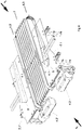
- the Figure 1 a collecting and conveying device 1 for collecting and conveying sheet-shaped printed products 5.
- the printed products are preferably in the form of unstapled stacks of sheet-shaped printed products, such as. B. paper, especially flat sheets, cardboard or the like. These are conveyed to a downstream conveyor line and / or to a device which processes the printed products further downstream.
- These unstapled stacks of sheet-shaped printed products can originate, for example, from an upstream intermediate store and be composed of, in particular, separately stored, different individual sheets.
- This Intermediate storage can be designed, for example, in a so-called tower (tower storage) with a large number of individual, preferably one above the other, partial storage (compartments).
- Loose sheets to be joined together to form a booklet or brochure can be temporarily stored therein, a set of sheets to be joined can be removed per machine cycle, combined into a stack and fed to the collecting and further conveying device 1.
- the collecting and further conveying device 1 is in a housing 2 (see Fig. Fig. 6 ) and has feed means 3 for feeding the printed products 5 into the collecting and further conveying device 1 and further conveying means 4 for their further conveyance.
- the further conveying direction 4.1 of the further conveying means 4 is directed transversely to the conveying direction 3.1 of the feeding means 3 for the printed products 5 to be collected and conveyed.
- variable length adjustable conveying path 3.2 is provided for adapting to different formats of printed products 5 to be collected and conveyed further (e.g. from credit card size to A3).
- the length variability of the conveyor line 3.2 can be achieved by one or more, e.g. B. two deflected conveyor belts 3.4 are effected, the distance between two deflection rollers 3.5, 3.6 at the opposite ends of the conveyor line 3.2 is variable, in that at least the deflection roller 3.5 closer to the further conveying means 4 is displaceable.
- a telescopic holder can be provided between the two end pulleys 3.5, 3.6.
- the roller 3.5 must give way to the belt 4.3 closely (cross belt becomes wider) or follow (cross belt becomes narrower), i.e. it must be adjustable.
- the deflection rollers 3.7, 3.8, 3.9, 3.10 of which at least one is also arranged to be adjustable.
- the roles 3.6, 3.8, 3.9 and 3.10 preferably remain fixed.
- the deflection rollers 3.5 and 3.6 form two end-side deflection rollers.
- the two pulleys 3.7 and 3.9 which are each located in a loop of the conveyor belt 3.4, are able to achieve length compensation for the corresponding conveyor belt 3.4 when the conveyor line 3.2 is adjusted by vertical adjustment.
- the length compensation can also take place by horizontal displacement of a deflection roller in a corresponding tape loop.
- the conveyor-side end 3.3 of the variable-length conveyor section 3.2 (see Sect. Figure 2 ) is designed to be position-adjustable, in particular with respect to a longitudinal axis 4.10 running through the further conveying means in the further conveying direction 4.1.
- conveyor rollers and / or conveyor belts 4.3; 4.3 ' for the further conveyance of the printed products 5 to be further conveyed, conveyor rollers and / or conveyor belts 4.3; 4.3 'for the further conveying means 4 on the printed products 5, in the illustrated embodiment from the underside of the printed products 5.
- additional cams are provided on the conveyor belts, which can act from behind to support the stack of paper. Such cams are in the figures on the downstream side of the conveyor belts 4.3; 4.3 ', protruding from the respective band.
- the distance 4.4 between the conveyor rollers and / or conveyor belts 4.3; 4.3 ' is adjustable for setting the conveyor width for the printed products 5 to be collected and further conveyed, for example by means of the in Figure 3 visible drive spindle 4.5 and supported and guided by two non-visible linear axes to the left and right of the drive spindle 4.5.
- the small rails 4.6 in Figure 3 serve to support the support plates 7.1.
- a support unit 7 is arranged for the printed products 5 to be collected and conveyed on.
- This support unit 7 can, in relation to the onward conveying direction 4.1, be adjustable in its width, as symbolized by the double arrow.
- the support unit 7 is designed as a support draw grid, in particular as a support draw grid that is adjustable in width.
- the support unit 7, that is to say the drawn grid 7, is fastened with one side to the housing of the belt 4.3 and with the other side to the housing of the belt 4.3 '.
- the support unit 7 that is to say the drawn grid 7, is fastened with one side to the housing of the belt 4.3 and with the other side to the housing of the belt 4.3 '.
- the entire transverse belt 4 including the vibrator is rotatably mounted around the front, downstream drive shaft and can raise its upstream end so far that it protrudes beyond the infeed belt 3 and thus lifts the stack that has come to rest on it, so that the transverse transport (in the main transport direction 4.10) is initiated without the stack of loose sheets getting stuck on the infeed belt 3.
- Figure 1 is the cross belt raised, in Figure 2 it is lowered.
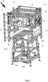
- the collecting and further conveying device 1 for collecting and further conveying sheet-shaped printed products 5 in the housing 2 is arranged in a height-adjustable manner.
- Spindle drives 1.1 are used for this in this version.
- a pass-through device 8 for the pass-through and output of printed products to the same output point as the collecting and further conveying device 1 for collecting and further conveying sheet-shaped printed products is arranged in the housing 2.
- This pass-through device 8 for the pass-through and output of printed products 5 is also arranged in the housing 2 in a height-adjustable manner.
- Spindle drives 8.1 can also be provided for this purpose.
Abstract
Die Erfindung betrifft eine Sammel- und Weiterfördervorrichtung (1) zum Sammeln und Weiterfördern von blattförmigen Druckereiprodukten (5), vorzugsweise ungehefteten Stapeln aus blattförmigen Druckereiprodukten, wie z. B. Papier, insbesondere Planobogen, Karton oder dergleichen, zu einer stromabwärtigen Förderstrecke und/oder zu einer stromabwärtig die Druckereiprodukte weiter bearbeitenden Vorrichtung, mit einem Gehäuse und Zufördermitteln (3) für die Zufuhr der Druckereiprodukte (5) in die Sammel- und Weiterfördervorrichtung und Weiterfördermitteln (4) für deren Weiterförderung. Diese zeichnet sich dadurch aus, dass die Weiterförderrichtung (4.1) der Weiterfördermittel (4) quer zur Förderrichtung (3.1) der Zufördermittel (3) für die zu sammelnden und zu fördernden Druckereiprodukte (5) gerichtet ist.The invention relates to a collecting and further conveying device (1) for collecting and further conveying sheet-shaped printed products (5), preferably unstapled stacks of sheet-shaped printed products, such as, for. B. paper, in particular flat sheets, cardboard or the like, to a downstream conveyor line and / or to a downstream device further processing the printed products, with a housing and feed means (3) for feeding the printed products (5) into the collecting and further conveying device and Further funding (4) for their further funding. This is characterized in that the further conveying direction (4.1) of the further conveying means (4) is directed transversely to the conveying direction (3.1) of the feeding means (3) for the printed products (5) to be collected and conveyed.
Description
Die Erfindung betrifft eine Sammel- und Fördervorrichtung zum Sammeln und Fördern von blattförmigen Druckereiprodukten nach Anspruch 1The invention relates to a collecting and conveying device for collecting and conveying sheet-shaped printed products according to
In Druckweiterverarbeitungsbetrieben und Verlagen werden Druckereiprodukte mit unterschiedlichsten Anforderungen und Formaten hergestellt. Dabei wird bedrucktes Papier unter anderem gestapelt, ausgerichtet, geklebt, geheftet und/oder auch gefaltet bzw. gefalzt.In print processing companies and publishing houses, printed products are manufactured with a wide variety of requirements and formats. Among other things, printed paper is stacked, aligned, glued, stapled and / or also folded or creased.
Insbesondere durch die fortschreitende Digitalisierung werden häufig auch verhältnismäßig kleine Lose verarbeitet. Dadurch bedingt steigen die Anzahl der zwischen den einzelnen Losen erforderlichen Umrüstungen der Maschinen zu deren Einstellung auf das nächste Format und die damit erforderlichen Umrüstzeiten von oft größer 30 Minuten verhältnismäßig stark an. Zusätzlich fallen die ständig steigenden Kosten für die zur Aufstellung der erforderlichen Vorrichtungen zur Verarbeitung von Druckereiprodukten benötigte Grundfläche immer mehr ins Gewicht.In particular, due to the advancing digitization, relatively small batches are often processed. As a result, the number of machine retooling required between the individual batches to adjust it to the next format, and the retooling times of often greater than 30 minutes required, increase relatively sharply. In addition, the constantly increasing costs for the floor space required to set up the necessary devices for processing printed products are becoming more and more important.
Der Erfindung liegt die Aufgabe zugrunde, die Betriebskosten für die Verarbeitung von Druckereiprodukten zu senken.The invention is based on the object of lowering the operating costs for processing printed products.
Die Lösung der Aufgabe erfolgt ausgehend von einer Vorrichtung gemäß dem Oberbegriff des Anspruchs 1 durch dessen kennzeichnende Merkmale. In den abhängigen Ansprüchen sind zweckmäßige und vorteilhafte Weiterbildungen angegeben.The object is achieved on the basis of a device according to the preamble of
Dementsprechend betrifft die Erfindung eine Sammel- und Weiterfördervorrichtung zum Sammeln und Weiterfördern von blattförmigen Druckereiprodukten, vorzugsweise ungehefteten Stapeln aus blattförmigen Druckereiprodukten, wie z. B. Papier, insbesondere Planobogen, Karton oder dergleichen, zu einer stromabwärtigen Förderstrecke und/oder zu einer stromabwärtig die Druckereiprodukte weiter bearbeitenden Vorrichtung, mit einem Gehäuse und mit Zufördermitteln für die Zufuhr der Druckereiprodukte in die Sammel- und Weiterfördervorrichtung und mit Weiterfördermitteln für deren Weiterförderung. Diese Sammel- und Weiterfördervorrichtung zeichnet sich dadurch aus, dass die Weiterförderrichtung der Weiterfördermittel quer zur Förderrichtung der Zufördermittel für die zu sammelnden und zu fördernden Druckereiprodukte gerichtet ist.Accordingly, the invention relates to a collecting and conveying device for collecting and conveying sheet-shaped printed products, preferably unstapled stacks of sheet-shaped printed products, such as. B. paper, in particular flat sheets, cardboard or the like, to a downstream conveyor line and / or to a downstream device further processing the printed products, with a housing and with conveying means for feeding the printed products into the collecting and further conveying device and with further conveying means for their further conveyance . This collecting and further conveying device is characterized in that the further conveying direction of the further conveying means is directed transversely to the conveying direction of the feeding means for the printed products to be collected and conveyed.
Eine separate Stellfläche für eine derart aufgebaute Sammel- und Weiterfördervorrichtung ist in platz- und damit kostensparender Weise nicht erforderlich. Sie kann direkt in die Linie einer Sammelstrecke, z.B. einer Heftmaschine, integriert werden, ggf. auf dieser aufgesetzt. Auf der dadurch frei verfügbaren Fertigungsfläche neben der Sammellinie kann anstelle dessen z.B. ein Vorrat an zu verarbeitenden Druckereiprodukten positioniert werden. Beispielsweise in der Form eines Turmregals, ggf. mit einer Abgabeeinheit zur Abgabe loser Blätter oder Planobogen, insbesondere in der Form eines Stapels solcher losen Blätter oder Planobogen, an die Sammel- und Weiterfördervorrichtung.A separate floor space for a collecting and further conveying device constructed in this way is not required in a space-saving and thus cost-saving manner. It can be placed directly in the line of a collecting line, e.g. a stapling machine, integrated, if necessary placed on top of it. Instead, for example, a supply of printed products to be processed can be positioned on the production area that is freely available next to the collecting line. For example in the form of a tower shelf, possibly with a delivery unit for delivering loose sheets or flat sheets, in particular in the form of a stack of such loose sheets or flat sheets, to the collecting and further conveying device.
Weitere Vorteile einer derartigen Sammel- und Weiterfördervorrichtung zum Sammeln und Weiterfördern von blattförmigen Druckereiprodukten sind eine damit mögliche kompaktere Anordnung und Integration in eine Fertigungslinie und damit einhergehend kürzere Wege für das Bedienpersonal zwischen den einzelnen Vorrichtungen zur Herstellung von Druckereiprodukten und damit eine, summarisch massiv mögliche Reduzierung der jeweils anteiligen Arbeitskosten durch reduzierten Weg- und damit Zeitaufwand.Further advantages of such a collecting and further conveying device for collecting and further conveying sheet-shaped printed products are a possible more compact arrangement and integration in a production line and, consequently, shorter distances for the operating personnel between the individual devices for the production of printed products and thus an overall massive possible reduction the respective pro rata labor costs due to reduced travel and thus time expenditure.
Denn der Anteil der Arbeitskosten am Klammerpreis bzw. am fertigen Druckereiprodukt ist etwa 10 mal so hoch wie der Anteil der Amortisationskosten. Konstruktive Maßnahmen, welche die Arbeitskosten senken, wirken sich deshalb vergleichsweise stark aus, ebenso wie die Verringerung der benötigten Grundfläche für die Verarbeitungsmaschine oder, besser, der Kette von Maschinen bzw. Vorrichtungen zur Herstellung von Druckereiprodukten. Daher nochmals aufgelistet die Vorteile einer solchen Sammel- und Weiterfördervorrichtung:
- platzsparend durch Integration mehrerer Verarbeitungsmöglichkeiten von Druckereiprodukten in eine Linie,
- platzsparend durch Übereinander-Anordnung verschiedener Verarbeitungswege,
- zeitsparend beim Einlernen durch einheitliches Bedienkonzept von vorn bis hinten,
- zeitsparend durch automatische Umrüstung (FormatUmstellung) durch Stellmotoren überall,
- vielfältig durch Ausbau der Linie mit zahlreichen unterschiedlichen Verarbeitungs-Optionen.
- space-saving thanks to the integration of several processing options for printed products in one line,
- space-saving thanks to the arrangement of different processing routes,
- time-saving when teaching-in thanks to a uniform operating concept from front to back,
- time-saving thanks to automatic conversion (format conversion) by servomotors everywhere,
- diverse by expanding the line with numerous different processing options.
Bei der Sammel- und Weiterfördervorrichtung zum Sammeln und Weiterfördern von blattförmigen Druckereiprodukten handelt es sich insbesondere um eine Umlenkeinheit, welche die Förderrichtung eines ungehefteten Bogenstapels um vorzugsweise 90° in der waagerechten Ebene ändert, wobei die Ausrichtung der Bogenstapel gleich bleibt.The collecting and further conveying device for collecting and further conveying sheet-shaped printed products is in particular a deflection unit which changes the conveying direction of an unstapled stack of sheets by preferably 90 ° in the horizontal plane, with the orientation of the stack of sheets remaining the same.
Dies ermöglicht einen alternativen Nebenstrom, von z.B. einem sogenannten Abzugsturm (mehrere Kassetten mit zu verarbeitenden Druckereiprodukten übereinander angeordnet) kommend, um quer zu einer Haupttransportrichtung einer Druckerzeugnis-Verarbeitungsanlage (z.B. eines Sammelhefters oder Klebebinders mit Digifinisher-Erweiterung) platzsparend einzuschleusen. Denn dies ist eine vorteilhafte Anordnung, damit der Bediener kurze Wege hat.This enables an alternative secondary flow, e.g. coming from a so-called haul-off tower (several cassettes with printed products to be processed, arranged one above the other), in order to smuggle in space-saving transversely to a main transport direction of a printed product processing system (e.g. a saddle stitcher or perfect binder with digifinisher extension). Because this is an advantageous arrangement so that the operator has short distances.
Hierbei ist es ggf. erforderlich, Länge und Breite der zur Erstellung eines Druckereiproduktes, z.B. einer Broschüre, der Zufuhr- und Umlenkfördermittel auf die zuzufördernden Bogenstapel einzustellen, um die korrekte Führung und den Zusammenhalt des ungehefteten Bogenstapels sicherzustellen. Dieser Stapel darf nicht auseinanderrutschen und muss exakt mittig und gerade ausgerichtet in die nachgeschaltete Vorrichtung, z.B. eine Rill-Falz-Einheit, übergeben werden. Weitere Details zur Sammel- und Weiterfördervorrichtung im Allgemeinen und im Speziellen hierzu werden weiter nachfolgend noch näher beschrieben.Here it may be necessary to adjust the length and width of the feed and deflection conveyor for the creation of a printed product, e.g. a brochure, on the stack of sheets to be fed in order to ensure the correct guidance and cohesion of the unstapled stack of sheets. This stack must not slide apart and must be exact be transferred centrally and aligned straight into the downstream device, eg a creasing-folding unit. Further details on the collecting and further conveying device in general and in particular on this are described in more detail below.
Gemäß einer bevorzugten Ausführungsform kann für die Zufördermittel eine längenvariabel verstellbare Förderstrecke zur Anpassung an verschiedene Formate von zu sammelnden und weiterzufördernden Druckereiprodukten vorgesehen sein.According to a preferred embodiment, a variable-length adjustable conveyor path for adaptation to different formats of printed products to be collected and conveyed on can be provided for the feed means.
Damit können die Förderlänge und/oder die Übergabelinie von den Zufuhrfördermitteln an die Weiterfördermittel an unterschiedliche Formate und Längen von zu sammelnden und weiterzufördernden Druckereiprodukten angepasst werden. Zudem ist dadurch eine Anpassung ihres Abstandes zu den Weiterfördermitteln möglich, welche z.B. in der Form eines Transportriemen umfassenden, sogenannten Querbands realisiert sein können, wie nachfolgend noch näher beschrieben. Der Abstand wiederum ist unter anderem abhängig vom Format der zu verarbeitenden Druckereiprodukte.In this way, the conveying length and / or the transfer line from the supply conveying means to the further conveying means can be adapted to different formats and lengths of printed products to be collected and further conveyed. In addition, an adjustment of their distance to the further conveying means is possible, which can be implemented, for example, in the form of a so-called cross belt comprising a transport belt, as described in more detail below. The distance in turn depends, among other things, on the format of the printed products to be processed.
Die Formate der Sammel- und Weiterfördervorrichtung zum Sammeln und Weiterfördern von blattförmigen Druckereiprodukten können beispielsweise zwischen Scheckkartenformat und A3 liegen.The formats of the collecting and further conveying device for collecting and further conveying sheet-shaped printed products can, for example, be between credit card format and A3.
Besonders bevorzugt ist dabei das förderseitige Ende der längenvariabel verstellbaren Förderstrecke positionsverstellbar ausgebildet, insbesondere gegenüber einer durch die Weiterfördermittel in Weiterförderrichtung verlaufenden Längsachse.Particularly preferably, the conveying-side end of the variable-length conveying path is designed to be adjustable in position, in particular with respect to a longitudinal axis running through the further conveying means in the further conveying direction.
Dadurch kann die Längenveränderung der Förderstrecke direkt am Ort der Übergabe erfolgen und ggf. eine Anpassung an unterschiedliche Eigenschaften verschiedener Druckereiprodukte ermöglicht werden.As a result, the change in length of the conveyor line can take place directly at the point of transfer and, if necessary, an adaptation to different properties of different printed products can be made possible.
Ein weiterer Vorteil liegt darin, dass die Position des Zulauf- oder Übernahmebereichs der längenvariabel verstellbaren Förderstrecke unverändert bleiben kann. D.h., es ist keine zeit- und damit kostentreibende Umrüstung bei einem Formatwechsel in diesem Bereich erforderlich.Another advantage is that the position of the inlet or takeover area of the variable-length adjustable conveyor line can remain unchanged. This means that no time-consuming and therefore costly retooling is required when changing formats in this area.
Gemäß einer weiter vorteilhaften Ausführungsform kann ein positionsvariabel verstellbarer, vorzugsweise rüttelbar ausgebildeter Anschlag für die zu sammelnden und weiterzufördernden Druckereiprodukte vorgesehen sein, insbesondere zur Anpassung an verschiedene Formate solcher Druckereiprodukte und/oder zur Ausrichtung übereinanderliegender Druckereiprodukte zueinander.According to a further advantageous embodiment, a variable-position, preferably vibratable stop can be provided for the printed products to be collected and conveyed on, in particular to adapt to different formats of such printed products and / or to align printed products on top of one another.
Das Rütteln des Anschlags kann z.B. durch entsprechend angesteuerte Stellantriebe erzeugt werden, z.B. zur Ausbildung eines Stapels mit sauberen Kanten aus den zu sammelnden und weiterzufördernden Druckereiprodukten.The jarring of the stop can be generated, for example, by appropriately controlled actuators, e.g. to create a stack with clean edges from the printed products to be collected and conveyed on.
Mit anderen Worten beschrieben, geht es darum, dem Stapel von losen Blättern auf seinem Förderweg eine Richtungsumkehr zu geben. Hierfür wird in der Sammel- und Weiterfördervorrichtung bzw. Umlenkeinheit, welche die Förderrichtung des ungehefteten Bogenstapels um vorzugsweise 90° in der waagerechten Ebene ändert, wobei die Ausrichtung der Bogenstapel gleich bleibt, am Anfang eine Einlauf-Einheit vorgesehen, die den Stapel von außen aus Richtung des Abzugsturms übernimmt und bis an einen formatabhängig einstellbaren Anschlag fördert. Danach übernimmt den weiteren Transport des Stapels, diesmal quer zur Einlaufrichtung und damit nun parallel zur Sammelrichtung, vorzugsweise einer Sammelkette, ein Querfördermittel, z.B. ein aus zwei parallelen Transportriemen bestehendes Querband.In other words, it is a matter of reversing the direction of the stack of loose sheets on its conveying path. For this purpose, in the collecting and further conveying device or deflection unit, which changes the conveying direction of the unstapled stack of sheets by preferably 90 ° in the horizontal plane, whereby the alignment of the stack of sheets remains the same, an inlet unit is provided at the beginning, which takes over the stack from the outside from the direction of the haul-off tower and conveys it to a stop that can be adjusted depending on the format. Then the further transport of the stack, this time transversely to the infeed direction and thus now parallel to the collecting direction, preferably a collecting chain, is carried out by a transverse conveyor, for example a transverse belt consisting of two parallel transport belts.
Der Abstand der beiden Transportriemen kann formatabhängig eingestellt werden. Dazwischen befindet sich ein Ziehgitter, damit nichts durchfällt.The distance between the two transport belts can be adjusted depending on the format. In between there is a grille so that nothing falls through.
Das Querband muss während des Einlaufs in die Umlenkeinheit vom zuzuführenden Stapel an Druckereiprodukten überfahren werden, ohne dass der lose Blattstapel zwischen den Transportriemen des Querbands oder am Ziehgitter hängenbleibt. Dafür gibt es eine Hilfsvorrichtung, einen sogenannten Brückenschlitten. Er stützt den einlaufenden losen Stapel ab, damit er nicht zwischen die Querband-Riemen auf das Ziehgitter darunter fällt, und zieht sich zurück, bevor das Querband den Stapel aushebt.During the entry into the deflection unit, the cross belt must be passed over by the stack of printed products to be fed in, without the loose stack of sheets getting stuck between the transport belts of the cross belt or on the pull grate. There is an auxiliary device for this, a so-called bridge slide. It supports the incoming loose stack so that it does not fall between the crossbelt belts on the pull grate underneath, and pulls back before the crossbelt lifts the stack out.
Um den Stapel sicher vom Einlaufband abzuheben, erhebt sich die zufuhrferne Seite des Querbands und hebt den Stapel dadurch aus, und beginnt, ihn in Richtung Weiterverarbeitung (stromabwärts) zu transportieren. Sobald die letzte Kante des losen Stapels das Einlaufband verlassen hat, senkt sich das Querband wieder ab, und noch während des Quertransports in Richtung der stromabwärtigen Vorrichtung, z.B. der Rill-Falz-Einheit, kann nun ein weiterer Stapel in den Bereich des Einlaufbands zugeführt werden, der kurz vorher noch "besetzt" war.In order to safely lift the stack off the infeed belt, the side of the cross belt that is remote from the feed rises, lifting the stack out of the way and starting to transport it in the direction of further processing (downstream). As soon as the last edge of the loose stack has left the infeed belt, the transverse belt is lowered again, and a further stack can now be fed into the area of the infeed belt while it is being transported towards the downstream device, e.g. the creasing and folding unit , which was "occupied" shortly before.
Das Querband befördert den Stapel dann weiter, z. B. in die Rill-Falz-Einheit, wobei die Rillung genau rechtwinklig zur Einlaufkante erfolgen muss, was dadurch gesteuert wird, dass die beiden Bänder des Querbands unterschiedlich schnell laufen können.The cross belt then conveys the stack further, e.g. B. in the creasing-folding unit, the creasing must be done exactly at right angles to the inlet edge, which is controlled by the fact that the two bands of the transverse belt can run at different speeds.
Damit kann Rillfehlern aktiv gegensteuert werden. Dazu ist es vorteilhaft, wenn die beiden Transportriemen des Querbands einen möglichst großen Abstand haben, weshalb ihr Abstand verstellbar ist. Dadurch können unterschiedliche Formate verarbeitet werden, insbesondere auch kleine Formate, bis hin zu Scheckkartenformaten.This means that creasing errors can be actively counteracted. For this purpose, it is advantageous if the two transport belts of the transverse belt are as far apart as possible, which is why their spacing is adjustable. As a result, different formats can be processed, especially small formats up to credit card formats.
Und weil das Einlaufband (das vom Abzugsturm kommt) genau bis an den einlaufnahen, allgemein gesprochen bis zum ersten oder vorderen Transportriemen des Querbands reichen muss, dieses aber verstellbar ist, muss auch die Länge des Einlaufbands verstellt werden können. Denn die Position des Anfangs des Einlaufbands ist fest (invariabel) in Bezug auf das Gehäuse der Sammel- und Weiterfördervorrichtung, damit von außen her immer die gleiche Übernahme- bzw. Übergabeposition gegenüber einer stromaufwärtig zu positionierenden Zuführvorrichtung sichergestellt werden kann.And because the infeed belt (which comes from the take-off tower) must reach exactly to the infeed, generally speaking to the first or front transport belt of the cross belt, but this is adjustable, the length of the infeed belt must also be adjustable. This is because the position of the start of the infeed conveyor is fixed (invariable) in relation to the housing of the collecting and further conveying device, so that the same takeover or transfer position can always be ensured from the outside in relation to a feed device to be positioned upstream.
Eine solche, an die Übernahmeposition der Sammel- und Weiterfördervorrichtung anzudockende Übergabeposition kann z.B. in der Form des Endes eines Schrägaufzugs realisiert sein, der die aus dem Abzugsturm entnommenen und zu einem losen, ungehefteten Stapel zusammengefügten Druckereiprodukte zuführt.Such a transfer position to be docked to the takeover position of the collecting and further conveying device can be implemented, for example, in the form of the end of an inclined elevator that feeds the printed products removed from the haul-off tower and assembled into a loose, unstapled stack.
Um die bei der Zufuhr (beim Einlauf), bezogen auf die Hauptstromförderrichtung, stromabwärts weisende und beim anschließenden Quertransport dann vordere Kante des Stapels -die Ausrichtung des losen, ungehefteten Stapels bleibt dabei unverändert, nur die Transportrichtung wird um vorzugsweise 90° geändert- zusammenzustoßen, damit alle Blätter oder Bogen genau übereinander liegen, wird der Anschlag für den Stapel mittels Stopperzylinder positioniert.In order to collide with the downstream edge of the stack, which is pointing downstream in relation to the main flow conveying direction, and which is then the front edge of the stack during the subsequent transverse transport - the orientation of the loose, unstapled stack remains unchanged, only the transport direction is preferably changed by 90 °. So that all sheets or sheets are exactly on top of each other, the stop for the stack is positioned by means of a stopper cylinder.
Die beiden Querbänder werden mit Servomotoren angetrieben. Dadurch können sie in sehr rascher Folge von einer Antriebsrichtung in die entgegengesetzt Richtung und auch wieder zurück umgeschaltet werden. Dies kann dazu genutzt werden, einen darauf zugeführten und abgelegten Blattstapel ggf. wiederholt gegen eine, entsprechend des zu fördernden Formats positionierbare Anschlagsfläche "aufzustoßen", so dass die einzelnen Blätter zu einem Stapel mit sauberen Kanten zusammenrutschen. Zur Positionierung der Anschlagsfläche entsprechend des zu fördernden Formats sind sogenannte Stopperzylinder vorgesehen. Entsprechend können sogenannte Seitenanschläge ein Rütteln des Stapels an dessen beiden anderen Seiten übernehmen. D.h., der zu- und weiterzufördernde Stapel loser, ungehefteter Druckereiprodukte kann sowohl von vorne und von hinten als auch von links und rechts zusammengerüttelt werden.The two cross belts are driven by servomotors. As a result, they can be switched from one drive direction to the opposite direction and back again in very quick succession. This can be used to repeatedly "push" a stack of sheets fed and deposited thereon against a stop surface that can be positioned according to the format to be conveyed, so that the individual sheets slide together to form a stack with clean edges. So-called stopper cylinders are provided for positioning the stop surface in accordance with the format to be conveyed. Accordingly, so-called side stops can shake the stack on its other two sides. This means that the stack of loose, unstapled printed products to be fed in and on can be jogged together from the front and back as well as from the left and right.
Im Weiteren ist es besonders bevorzugt, wenn für die Weiterfördermittel zwei Antriebe, insbesondere Servoantriebe vorgesehen sind, die die Transportriemen der Weiterfördervorrichtung, auf denen die weiterzufördernden Druckereiprodukte weitergefördert werden, jeweils separat voneinander in Weiterförderrichtung antreiben.In addition, it is particularly preferred if two drives, in particular servo drives, are provided for the further conveying means, which drive the conveyor belts of the further conveying device on which the further conveying devices Printed products are conveyed further, each drive separately from one another in the further conveying direction.
Damit kann auf jede der beiden Transportseiten der weiterzufördernden Druckereiprodukte einzeln eingewirkt werden.This means that each of the two transport sides of the printed products to be conveyed can be acted upon individually.
Vorteilhafter Weise wirken die Weiterfördermittel, in Weiterförderrichtung betrachtet, auf die weiterzufördernden Druckereiprodukte jeweils in deren linken und rechten Randbereich auf sie ein, insbesondere mittels Förderrollen und/oder Förderbändern, vorzugsweise von der Unterseite der Druckereiprodukte her und insbesondere mittels an den Förderbändern vorgesehenen Nocken, zur Stützung des Stapels, in Förderrichtung betrachtet, von hinten her. Diese Nocken können von der Förderfläche des jeweiligen Förderbandes nach außen abstehen, also bei einem rund umlaufenden Band an der Oberseite nach oben und an der Unterseite nach unten, um jeweils einen sogenannten Mitnehmer für den zu fördernden Bogenstapel auszubilden.The further conveying means, viewed in the further conveying direction, act on the printed products to be further conveyed in their left and right edge areas, in particular by means of conveyor rollers and / or conveyor belts, preferably from the underside of the printed products and in particular by means of cams provided on the conveyor belts Support of the stack, viewed in the conveying direction, from the rear. These cams can protrude outward from the conveying surface of the respective conveyor belt, that is to say in the case of a circumferential belt upwards on the upper side and downward on the underside, in order to each form a so-called driver for the stack of sheets to be conveyed.
Insbesondere können die beiden Antriebe der Weiterfördermittel zur Ausrichtung der damit weiterzufördernden Druckereiprodukte zumindest temporär mit unterschiedlichen Geschwindigkeiten und/oder mit unterschiedlichen Förderrichtungen ansteuerbar ausgebildet sein.In particular, the two drives of the further conveying means for aligning the printed products to be conveyed further can be designed to be controllable at least temporarily at different speeds and / or with different conveying directions.
Damit ist eine Ausrichtung der ungehefteten Bogenstapel auf kürzester Strecke und in kürzester Zeit, z.B. in Millisekunden, möglich, insbesondere aufgrund hoher Wirksamkeit und Genauigkeit durch die große Hebelwirkung der Antriebe auf die Bogenstapel an deren äußeren Bereichen.This enables the unstapled sheet stacks to be aligned over the shortest distance and in the shortest possible time, for example in milliseconds, in particular due to the high efficiency and accuracy due to the great leverage of the drives on the sheet stacks at their outer areas.
Die Ausbildung eines Stapels mit sauberen Kanten aus den zu sammelnden und weiterzufördernden Druckereiprodukten wirkt sich massiv auf die Qualität der Endprodukte aus. Dies ist um so wichtiger, wenn kein abschließender Zuschnitt der Seiten der fertigen Druckereiprodukte vorgesehen ist.The formation of a stack with clean edges from the printed products to be collected and forwarded has a massive effect on the quality of the end products. This is all the more important if no final cutting of the sides of the finished printed products is provided.
Beispielsweise können die Stapel weiterzufördender Druckereiprodukte auf eine zentrale Förderstrecke einer Heftvorrichtung abgegeben werden, z.B. zur Vorbereitung eines einem Heftvorgang vorangehenden Falzvorgangs, insbesondere eines sogenannten Rill-Falzvorgangs. Dafür ist es ganz entscheidend, dass die Stapel exakt ausgerichtet und mit sauberen Kanten zugeführt werden.For example, the stacks of printed products to be conveyed on can be delivered to a central conveyor line of a stapling device, e.g. to prepare a folding process preceding a stapling process, in particular a so-called creasing process. For this it is very important that the stacks are precisely aligned and fed with clean edges.
Zur Anpassung der Weiterfördervorrichtung an verschiedene Formate zu sammelnder und weiterzufördernder Druckereiprodukte kann in einer weiter vorteilhaften Ausführung der Abstand zwischen den Förderrollen und/oder Förderbändern zur Einstellung der Förderbreite für die weiterzufördernden Druckereiprodukte verstellbar sein.To adapt the onward conveying device to different formats of printed products to be collected and conveyed on, in a further advantageous embodiment the distance between the conveyor rollers and / or conveyor belts can be adjustable for setting the conveying width for the printed products to be conveyed on.
In einer insbesonders bevorzugten Ausführungsform können zur Einstellung der Förderbreite auch sogenannte Seitenanschläge verstellt werden. Dieser Verstellung sollte der Abstand der Querbänder in einem gewissen, relativ großen Rahmen folgen können, um zum einen die Wirksamkeit der Ausrichtung der Vorderkante über die beiden Transportriemen zu garantieren und zum anderen zu vermeiden, dass ein Stapel sich in den Seitenanschlägen verkantet.In a particularly preferred embodiment, so-called side stops can also be adjusted to adjust the conveyor width. The distance between the transverse belts should be able to follow this adjustment within a certain, relatively large framework in order, on the one hand, to guarantee the effectiveness of the alignment of the front edge over the two transport belts and, on the other hand, to avoid a stack jamming in the side stops.
Zur Abstützung der zu sammelnden und weiterzufördernden Druckereiprodukte kann gemäß einer weiteren Ausführungsform zwischen den Förderrollen und/oder den Förderbändern eine Auflageeinheit für die zu sammelnden und weiterzufördernden Druckereiprodukte angeordnet sein, insbesondere eine, bezogen auf die Weiterförderrichtung, in ihrer Breite vorzugsweise automatisch verstellbare Auflageeinheit.To support the printed products to be collected and further conveyed, according to a further embodiment, a support unit for the printed products to be collected and further conveyed can be arranged between the conveyor rollers and / or the conveyor belts, in particular a support unit that is preferably automatically adjustable in width in relation to the further conveying direction.
Dies erleichtert die Anpassung/Umrüstung der Weiterfördervorrichtung an verschiedene Formate von zu sammelnden und zu fördernden Druckereiprodukten, insbesondere deren automatisierte Umrüstung.This facilitates the adaptation / conversion of the further conveying device to different formats of printed products to be collected and conveyed, in particular their automated conversion.
Vorzugsweise sind die zu den Förderrollen und/oder Förderbändern weisenden Seiten der Auflageeinheit mit diesen verbunden, so dass bei deren Abstandsverstellung zugleich auch die Breite der Auflageeinheit mitverstellt wird.The sides of the support unit facing the conveyor rollers and / or conveyor belts are preferably connected to them, so that when the distance is adjusted, the width of the support unit is also adjusted at the same time.
Hierzu kann die Auflageeinheit als Auflage-Ziehgitter ausgebildet sein, insbesondere als breitenvariabel verstellbares, z.B. in der Form mehrerer aufgekantet nebeneinander angeordneter und in wechselnden Abständen miteinander verbundener, länglich flacher, insbesondere aufrecht bzw. senkrecht stehender Elemente, vergleichbar beispielsweise mit Stahllinealen. Die Verbindungen zwischen den einzelnen Elementen kann z.B. wechseln zwischen mittig und außen. Damit ist in der Breite eine gute "Zieharmonikawirkung" erzielbar, bei gleichzeitig hoher Stabilität zur Abstützung der weiterzufördernden Druckereiprodukte und auch geringem Widerstand in Weiterförderrichtung.For this purpose, the support unit can be designed as a support grille, in particular as a variable-width adjustable element, e.g. in the form of several elongated, flat, in particular upright or perpendicular elements, arranged side by side and connected at changing distances, comparable for example to steel rulers. The connections between the individual elements can, for example, alternate between the center and the outside. In this way, a good "accordion effect" can be achieved in terms of width, while at the same time providing high stability for supporting the printed products to be conveyed further and also low resistance in the further conveying direction.
Gemäß einer weiter bevorzugten Ausführungsform kann die Auflageeinheit positionsvariabel verstellbar, vorzugsweise in Weiterförderrichtung höhenverstellbar, insbesondere verkippbar ausgebildet sein, vorzugsweise zusammen mit den Förderrollen und/oder Förderbändern. Insbesondere bevorzugt kann das gesamte Querband einschließlich der Rüttler drehbar um die Antriebswelle gelagert sein und kann ihr stromaufwärtiges Ende so weit anheben, dass es das Einlaufband überragt und damit den darauf zur Ruhe gekommenen Stapel der zuzuführenden und weiterzufördernden Druckereiprodukte aushebt, damit der Quertransport eingeleitet werden kann, ohne dass der Stapel loser Blätter am Einlaufband hängenbleibt.According to a further preferred embodiment, the support unit can be variably adjustable in position, preferably adjustable in height in the further conveying direction, in particular tiltable, preferably together with the conveyor rollers and / or conveyor belts. Particularly preferably, the entire cross belt, including the vibrator, can be rotatably mounted around the drive shaft and can raise its upstream end so far that it protrudes beyond the infeed belt and thus lifts the stack of printed products to be fed and further conveyed that has come to a standstill on it, so that the cross transport can be initiated without the pile of loose sheets getting stuck on the infeed conveyor.
Dadurch kann eine gleichzeitige Verarbeitung zweier nacheinander zu sammelnder und weiterzufördernder Druckereiprodukte ermöglicht werden. Dies durch Abstützung des zweiten (nachfolgenden) Druckereiproduktes in gegenüber dem Ersten erhöhter Position, so dass das Erstere ohne Einwirkung des Letzteren, insbesondere auf dessen Ausrichtung und Stapelform der lose und ungeheftet aufeinander liegenden Blätter oder Bogen, weiter- und damit aus der Sammel- und Weiterfördervorrichtung abtransportiert werden kann.This enables the simultaneous processing of two printed products to be collected and conveyed one after the other. This is done by supporting the second (subsequent) printed product in an elevated position compared to the first, so that the former continues without any influence from the latter, in particular on its alignment and stacking form of the loose and unstapled sheets or sheets, and thus out of the collecting and Further conveying device can be transported away.
Der zweite (nachfolgende) Stapel gleitet auf den Zufördermitteln für die Zufuhr der Druckereiprodukte in die Sammel- und Weiterfördervorrichtung (dem Einlauf) längs über dem ersten (vorhergehenden) Stapel auf den Weiterfördermitteln (dem Querband). Die Zufördermittel (der Einlauf längs) sind dabei extrem schmal und in der Breite nicht verstellbar. Der von vorn einlaufende Stapel wird nur an seiner, in Bezug auf die Hauptförderrichtung, die mit der Weiterförderrichtung der Sammel- und Weiterfördervorrichtung übereinstimmt, stromaufwärtigen Seite im Einlauf längs festgehalten.The second (subsequent) stack slides on the conveying means for feeding the printed products into the collecting and further conveying device (the infeed) longitudinally above the first (previous) stack on the further conveying means (the transverse belt). The feed means (the infeed lengthways) are extremely narrow and cannot be adjusted in width. The stack entering from the front is only moved to its, in relation to the main conveying direction, which corresponds to the onward conveying direction of the Collecting and further conveying device matches, held upstream side in the inlet lengthways.
Die dieser gegenüberliegende Seite mit einer sehr großen freien Fläche überdeckt einen großen Teil des (relativ kurzen) Querbands. Aus diesem Grund ist es günstig, dass die Querbewegung zügig in die untere Etage verlegt wird, damit der Einlauf (von vorn) aus dem Abzugsturm genug Zeit hat, denn der braucht im Falle des Maximal-Formats entsprechend lange.The side opposite this with a very large free area covers a large part of the (relatively short) transverse band. For this reason, it is beneficial that the transverse movement is moved quickly to the lower level so that the entry (from the front) from the haul-off tower has enough time, because in the case of the maximum format it takes a correspondingly long time.
Dazu kann das gesamte Querband verkippen, einschließlich Rüttler und Stopperzylinder und Ziehgitter (es dreht sich dabei um wenige Grad um die stromabwärtige Antriebswelle), aber nur kurz zum Ausheben, damit der Stapel nicht am Einlaufband hängenbleibt. Dafür liegt es in der Ruhelage waagerecht und im Niveau unterhalb dem (immer waagerechten) Einlaufband. Zum Ausheben bleibt die Achse der stromabwärtigen (angetriebenen) Umlenkrolle stehen, und die stromaufwärtige Umlenkrolle (noch hinter dem Querband) hebt sich so weit, dass sie über der Ebene des Einlaufbands steht und damit den auf dem Einlaufband liegenden Stapel hochhebt.For this purpose, the entire cross belt can tilt, including the jogger and stopper cylinder and the pull grate (it rotates a few degrees around the downstream drive shaft), but only for a short time so that the stack does not get stuck on the infeed belt. In return, it lies horizontally in the rest position and at the level below the (always horizontal) infeed conveyor. For lifting, the axis of the downstream (driven) deflection roller stops, and the upstream deflection roller (still behind the cross belt) is raised so far that it is above the level of the infeed conveyor and thus lifts the stack on the infeed conveyor.
Zum Weitertransport stromabwärts senkt sich die stromaufwärtige Seite des Querbands schnell wieder ab, sobald das Einlaufband frei ist. Dadurch liegt der zweite (einlaufende) Stapel höher als der erste (quer dazu auslaufende).For further transport downstream, the upstream side of the transverse belt quickly lowers again as soon as the infeed belt is free. As a result, the second (incoming) stack is higher than the first (running out across it).
Dies kommt somit insbesondere bei vergleichsweise großen Abmessungen der zu sammelnden und weiterzufördernden Druckereiprodukte zum Tragen, z. B. größer als A5-Format, und erhöht massiv die Verarbeitungsgeschwindigkeit der Sammel- und Weiterfördervorrichtung, da während der Weiterförderung der Ersteren, ggf. bereits während der Ausrichtung eines Stapels auf den Förderrollen und/oder den Förderbändern, bereits Zweitere in die Sammel- und Weiterfördervorrichtung zugeführt und gesammelt werden können.This is particularly important in the case of comparatively large dimensions of the printed products to be collected and further conveyed, e.g. B. larger than A5 format, and massively increases the processing speed of the collection and Further conveying device, since during the further conveyance of the former, possibly already during the alignment of a stack on the conveyor rollers and / or the conveyor belts, the second can already be fed into the collecting and further conveying device and collected.
Um zu verhindern, dass bei starker Beschleunigung der Transportbänder die Blätter des Stapels auf den Transportbändern verrutschen können, sind an den Transportbändern zusätzlich Nocken vorgesehen, die von hinten stützend auf den Papierstapel einwirken können, um den Quertransport zu stabilisieren.In order to prevent the sheets of the stack from slipping on the conveyor belts when the conveyor belts accelerate rapidly, additional cams are provided on the conveyor belts, which can act on the stack of paper from behind in order to stabilize the transverse transport.
Mit anderen Worten läuft der erste Stapel auf dem Einlaufband (quer zur Hauptförderrichtung des Sammelhefters) ein, bis zum hinteren Anschlag, wird dann vom Querband (genauer, von dessen stromaufwärtiger Seite) ausgehoben, dann beginnt das Querband eine Bewegung stromabwärts bis zu den Stopperzylindern, also zur Rüttelstation (der Stapel fährt nun schräg nach unten), und sobald die stromaufwärts gerichtete Kante des nun auf dem Querband liegenden Stapels das Einlaufband verlassen hat, senkt sich das Querband wieder ab. Dann liegt der erste Stapel (auf dem Querband nach dessen Absenken) tiefer als der nun auf dem Einlaufband nachfolgende zweite, dessen stromabwärtige Kante über den ersten (vorhergehenden) hinweggleiten kann.In other words, the first stack runs on the infeed belt (transverse to the main conveying direction of the saddle stitcher) up to the rear stop, is then lifted by the cross belt (more precisely, from its upstream side), then the cross belt begins a movement downstream to the stopper cylinders, that is, to the vibrating station (the stack now moves diagonally downwards), and as soon as the upstream edge of the stack now lying on the transverse belt has left the infeed belt, the transverse belt is lowered again. Then the first stack (on the transverse belt after it has been lowered) is lower than the second one that now follows on the infeed belt, the downstream edge of which can slide over the first (previous one).
In vorteilhafter Weise kann damit die Vorderkante eines Stapels auf dem Querband mit zwei Servomotoren ausgerichtet werden.In this way, the leading edge of a stack can advantageously be aligned on the transverse belt with two servomotors.
Insbesondere ist es vorteilhaft, wenn die Vorrichtung umfasst:
- ein in der Breite verstellbares Querband und/oder
- einen längenverstellbaren Einlauf und/oder
- einen Brückenschlitten und/oder
- die Verwendung des Querbands als Rüttler längs der Transportbewegung und/oder
- die Verwendung von (z.B. Servo-)Motoren der Quer-Rüttler zum Ändern der Lage einer ggf. nachfolgend zu erstellenden Falzrille (indem die hierfür vorgesehene Position des Bogenstapels unsymmetrisch eingestellt wird), und/oder
- ein zwei-Ebenen-Konzept, so dass mit einem in der Höhe verstellbaren Gestell am gleichen Platz je nach Bedarf entweder eine 90°-Umlenkeinheit oder ein Überleittisch eingesetzt werden können, wie nachfolgend noch näher erläutert.
- a width-adjustable cross belt and / or
- a length-adjustable inlet and / or
- a bridge carriage and / or
- the use of the cross belt as a vibrator along the transport movement and / or
- the use of (eg servo) motors of the transverse jogger to change the position of a folding groove to be created subsequently (by setting the intended position of the sheet stack asymmetrically), and / or
- a two-level concept, so that either a 90 ° deflection unit or a transfer table can be used with a height-adjustable frame in the same place, as will be explained in more detail below.
Um die Sammel- und Weiterfördervorrichtung zum Sammeln und Weiterfördern von blattförmigen Druckereiprodukten umpositionieren zu können, kann diese im Gehäuse höhenverstellbar angeordnet sein, z. B. um Platz für eine andere an diese Stelle anzuordnende gewünschte Einheit zur Bearbeitung und/oder Förderung von Druckereiprodukten zu machen.In order to be able to reposition the collecting and further conveying device for collecting and further conveying sheet-shaped printed products, it can be arranged in a height-adjustable manner in the housing, e.g. B. to make room for another desired unit to be arranged at this point for processing and / or conveying printed products.
Eine mögliche Struktur für eine solche Umpositionierung kann beispielsweise ein Spindelantrieb sein. Solche Spindelantriebe sind vergleichsweise rasch und genau verstellbar, z.B. mittels eines Servoantriebs, und benötigen ansonsten keine Energie, um die eingestellte Position zuverlässig zu halten. Des Weiteren können sie hohe Lasten aufnehmen.A possible structure for such a repositioning can be, for example, a spindle drive. Such spindle drives can be adjusted comparatively quickly and precisely, e.g. by means of a servo drive, and otherwise do not require any energy to reliably hold the set position. They can also take heavy loads.
Eine solche Einheit zur Bearbeitung und/oder Förderung von Druckereiprodukten kann z.B. eine Durchschleusvorrichtung zur Durchschleusung und Ausgabe von Druckereiprodukten sein.Such a unit for processing and / or conveying printed products can be, for example, a pass-through device for passing through and outputting printed products.
Vorzugsweise eine mit einer linearen Durchschleusrichtung. Dadurch können bei Bedarf ggf. auch von weiteren, in gerader Linie stromaufwärts des Gehäuses angeordneten Stellen ebenfalls Druckereiprodukte an die stromabwärts des Gehäuses der Sammel- und Weiterfördervorrichtung zum Sammeln und Weiterfördern von blattförmigen Druckereiprodukten angeordneten Stellen zugeführt werden.Preferably one with a linear transit direction. As a result, if necessary, printed products can also be fed from further locations arranged in a straight line upstream of the housing to the locations arranged downstream of the housing of the collecting and further conveying device for collecting and further conveying sheet-shaped printed products.
Diese Durchschleusvorrichtung kann hierzu ebenfalls in dem Gehäuse angeordnet und so positionierbar sein, dass sie durchzuschleusende Druckereiprodukte vorzugsweise auf die gleiche Ausgabestelle wie die Sammel- und Weiterfördervorrichtung zum Sammeln und Weiterfördern von blattförmigen Druckereiprodukten ausgibt.This pass-through device can also be arranged in the housing for this purpose and can be positioned so that it outputs printed products to be passed through preferably to the same output point as the collecting and further conveying device for collecting and further conveying sheet-shaped printed products.
Dazu kann auch die Durchschleusvorrichtung zur Durchschleusung und Ausgabe von Druckereiprodukten höhenverstellbar im Gehäuse angeordnet sein. Vorzugsweise ebenfalls mittels eines Spindelantriebs. Dadurch kann bei Bedarf jeweils diejenige Einheit, also die Sammel- und Weiterfördervorrichtung zum Sammeln und Weiterfördern von blattförmigen Druckereiprodukten oder die Durchschleusvorrichtung, an der Position im Gehäuse positioniert werden, die für die Ausgabe der betreffenden Druckereiprodukte vorgesehen ist.For this purpose, the pass-through device for the pass-through and output of printed products can also be arranged in a height-adjustable manner in the housing. Preferably also by means of a spindle drive. As a result, if necessary, that unit, i.e. the collecting and further conveying device for collecting and further conveying sheet-shaped printed products or the transfer device, can be positioned at the position in the housing that is intended for the output of the relevant printed products.
Die Sammel- und Weiterfördervorrichtung zum Sammeln und Weiterfördern von blattförmigen Druckereiprodukten bzw. Umlenk-Einheit muss auch gespeist werden. Hierzu kann von papierflussmäßig stromaufwärts in Sammelrichtung vorzugsweise einer Sammelkette z.B. eine Falzmaschine (für einzelne Falzbogen oder Einzelblätter) und quer zur Sammelrichtung z.B. ein Abzugsturm für lose Stapel oder Einzelblätter angeschlossen werden.The collecting and further conveying device for collecting and further conveying sheet-shaped printed products or deflecting unit must also be fed. For this purpose, from the paper flow upstream in the collecting direction, preferably a collecting chain, for example a folding machine (for individual folded sheets or single sheets) and transversely to the collecting direction, for example a haul-off tower for loose stacks or single sheets can be connected.
Damit können Blätter, Falzbogen oder Blattstapel mittels der in die Ebene des Sammelstroms integrierbaren und aus dieser wieder entfernbaren Umlenkeinheit -mit unveränderter Blattausrichtung- eingespeist werden.In this way, sheets, folded sheets or stacks of sheets can be fed in by means of the deflecting unit which can be integrated into the plane of the collective flow and removed from it again - with unchanged sheet orientation.
Die Umlenk-Einheit ermöglicht damit eine Quereinspeisung von Druckereiprodukten, z. B. aus einem Abzugsturm, weil dieser dafür ausgelegt ist, quer, also von der Seite her zur Kettentransportrichtung, Bogenstapel in die Weiterverarbeitungsmaschine einzuspeisen. Und dazu muss die Transportrichtung der Bogen und/oder Stapel umgelenkt werden, nicht aber deren Ausrichtung.The deflection unit thus enables cross-feeding of printed products, e.g. B. from a take-off tower, because this is designed to feed transversely, so from the side to the chain transport direction, sheet stacks in the further processing machine. And for this, the transport direction of the sheets and / or stacks must be deflected, but not their alignment.
Wenn jedoch anstelle der Sammel- und Weiterfördervorrichtung zum Sammeln und Weiterfördern von blattförmigen Druckereiprodukten bzw. Umlenkvorrichtung stromaufwärts der Hauptförderrichtung z.B. eine weitere Falzmaschine betrieben werden soll, stünde die Umlenkeinheit im Weg, um von dieser stromaufwärtigen Vorrichtung Druckereiprodukte auf dem direkten Weg stromabwärts, beispielsweise zu einer dort angeordneten Vorrichtung, wie z.B. einer Rill-Falz-Einheit, fördern zu können. Deshalb sind o.a. Strukturen für eine solche Umpositionierung, wie eine Anhebung oder eine Absenkung, vorgesehen, beispielsweise Spindelantriebe.If, however, instead of the collecting and further conveying device for collecting and further conveying sheet-shaped printed products or deflecting device upstream of the main conveying direction, e.g. another folding machine is to be operated, the deflecting unit would be in the way of this upstream device, in order to transfer printed products on the direct path downstream, for example to a arranged there device, such as a creasing-folding unit to be able to promote. Therefore, the above-mentioned structures are provided for such repositioning, such as raising or lowering, for example spindle drives.
Damit kann sie hoch- oder runtergefahren und somit aus dem Weg geräumt und an deren Stelle eine andere Vorrichtung, wie z. B. ein Überleittisch, positioniert werden, um von der stromaufwärtigen Vorrichtung, wie einer Falzmaschine, einen Falzbogen oder von einem Rollenabschneider oder von einem Großformat-Anleger ein Einzelblatt an die Rill-Falz-Einheit zu übergeben. Sollen dann wieder Druckereiprodukte aus dem Turm verarbeitet werden, wird hierzu die eben beschriebene Umpositionierung von Sammel- und Weiterfördervorrichtung zum Sammeln und Weiterfördern von blattförmigen Druckereiprodukten bzw. Umlenkvorrichtung und z.B. Überleittisch in umgekehrter Reihenfolge durchgeführt.So it can be turned up or down and thus cleared out of the way and in its place another device, such as. B. a transfer table to be positioned by the upstream device, such as a folding machine, a Folded sheet or from a roll cutter or from a large format feeder to transfer a single sheet to the creasing-folding unit. If printed products from the tower are then to be processed again, the repositioning of the collecting and further conveying device just described for collecting and further conveying sheet-shaped printed products or deflecting device and, for example, transfer table is carried out in reverse order.
Vorzugsweise können sowohl die 90°-Umlenkeinheit als auch der insbesondere darunter angeordnete Überleittisch in einem Obergestell (Bühne) des Gehäuses angeordnet sein, welches mittels vierer Spindelantriebe in der Höhe gegenüber einem Grundgestell verstellt werden kann, so dass sich entweder die Umlenkeinheit oder der Überleittisch auf der Höhe des stromabwärtigen Teils der Papierverarbeitungsmaschine (vorzugsweise eine Rill-Falz-Einheit) befinden.Preferably, both the 90 ° deflection unit and the transfer table arranged underneath can be arranged in an upper frame (stage) of the housing, which can be adjusted in height relative to a base frame by means of four spindle drives, so that either the deflection unit or the transfer table is on the height of the downstream part of the paper converting machine (preferably a crease-crease unit).
Die 90°-Umlenkeinheit und der Überleittisch können bevorzugt gleichzeitig hoch und runter fahren. Damit ist nur ein Verstellvorgang von Nöten. Dabei ist die untere Position für die Umlenkeinheit gewählt und die obere für den Überleittisch, aber es ginge auch andersrum. Der Überleittisch baut jedoch deutlich flacher, also ist er unten. Weil nun aber der Überleittisch sehr flach (d.h. beengt) eingebaut ist und weil man in der Praxis Zugriff darauf haben muss, z.B. weil man einen Papierstau beseitigen muss, wird die darüber befindliche Umlenkeinheit bevorzugt in eine Oberbühne eingebaut, also in einen Rahmen, der gegenüber der Bühne noch mal angehoben werden kann. Dann bekommt der Überleittisch über sich Luft, und der Bediener hat darauf Zugriff.The 90 ° deflection unit and the transfer table can preferably move up and down at the same time. This means that only one adjustment process is necessary. The lower position is selected for the deflection unit and the upper position for the transfer table, but it could also work the other way around. However, the transfer table is much flatter, so it is at the bottom. But because the transfer table is installed very flat (i.e. cramped) and because in practice you have to have access to it, e.g. because you have to clear a paper jam, the deflection unit above is preferably installed in an upper platform, i.e. in a frame opposite the one the stage can be raised again. Then the transfer table gets air above it and the operator has access to it.
Auch für dieses Anheben der Oberbühne (=Freifahren der "Durchschleuseinheit") können bevorzugt Hubachsen bzw. Spindeln vorgesehen sein.Lifting axes or spindles can also preferably be provided for this lifting of the upper stage (= moving the "through-feed unit").
Demnach kann gemäß einer weiter bevorzugten Ausführungsform vorgesehen sein, dass die Sammel- und Weiterfördervorrichtung zum Sammeln und Weiterfördern von blattförmigen Druckereiprodukten gegenüber der Durchschleusvorrichtung zur Durchschleusung und Ausgabe von Druckereiprodukten im Gehäuse höhenverstellbar ausgebildet ist und/oder dass die Durchschleusvorrichtung zur Durchschleusung und Ausgabe von Druckereiprodukten gegenüber der Sammel- und Weiterfördervorrichtung zum Sammeln und Weiterfördern von blattförmigen Druckereiprodukten im Gehäuse höhenverstellbar ausgebildet ist.Accordingly, according to a further preferred embodiment, it can be provided that the collecting and further conveying device for collecting and further conveying sheet-shaped printed products is designed to be height-adjustable in relation to the transfer device for transferring and dispensing printed products in the housing and / or that the transfer device for transferring and dispensing printed products is opposite the collecting and further conveying device for collecting and further conveying sheet-shaped printed products in the housing is designed to be height-adjustable.
Für das Bedienpersonal bleiben in jedem Fall kurze, Zeit und damit Kosten sparende Wege erhalten.In any case, short, time-saving and thus cost-saving routes are retained for the operating personnel.
Nachfolgend wird unter Bezugnahme auf die beigefügten Figuren beispielhaft ein Ausführungsbeispiel näher erläutert.An exemplary embodiment is explained in more detail below with reference to the accompanying figures.
Es zeigen:
- Fig. 1 bis 5:
- jeweils beispielhaft eine perspektivische Ansicht auf eine Sammel- und Weiterfördervorrichtung, in unterschiedlich vervollständigten Zusammenbaustufen,
- Fig. 6:
- beispielhaft eine perspektivische Ansicht auf eine Sammel- und Weiterfördervorrichtung, zusammen mit einer Durchschleusvorrichtung in einem Gehäuse angeordnet.
- Fig. 1 to 5:
- each an example of a perspective view of a collecting and further conveying device, in differently completed assembly stages,
- Fig. 6:
- by way of example, a perspective view of a collecting and further conveying device, arranged together with a transfer device in a housing.
Dementsprechend zeigt die
Diese ungehefteten Stapel aus blattförmigen Druckereiprodukten können beispielsweise aus einem stromaufwärtigen Zwischenlager stammen und aus insbesondere separat gelagerten, unterschiedlichen Einzelbogen zusammengesetzt sein. Dieses Zwischenlager kann z.B. i.d.F. eines sogenannten Turms (Turmspeicher) mit einer Vielzahl einzelner, vorzugsweise übereinander angeordneter Teilspeicher (Fächer) ausgebildet sein. Darin können z.B. zu einem Heft oder Prospekt zusammenzufügende, lose Bogen zwischengelagert, jeweils pro Maschinentakt ein Satz zusammenzufügender Bogen entnommen, zu einem Stapel kombiniert und der Sammel- und Weiterfördervorrichtung 1 zugeführt werden.These unstapled stacks of sheet-shaped printed products can originate, for example, from an upstream intermediate store and be composed of, in particular, separately stored, different individual sheets. This Intermediate storage can be designed, for example, in a so-called tower (tower storage) with a large number of individual, preferably one above the other, partial storage (compartments). Loose sheets to be joined together to form a booklet or brochure can be temporarily stored therein, a set of sheets to be joined can be removed per machine cycle, combined into a stack and fed to the collecting and further conveying
Die Sammel- und Weiterfördervorrichtung 1 ist in einem Gehäuse 2 (s.
Die Weiterförderrichtung 4.1 der Weiterfördermittel 4 ist quer zur Förderrichtung 3.1 der Zufördermittel 3 für die zu sammelnden und zu fördernden Druckereiprodukte 5 gerichtet.The further conveying direction 4.1 of the further conveying
Bei den Zufördermitteln 3 ist eine längenvariabel verstellbare Förderstrecke 3.2 zur Anpassung an verschiedene Formate von zu sammelnden und weiterzufördernden Druckereiprodukten 5 (z.B. von Scheckkartengröße bis A3) vorgesehen.In the case of the conveying
Die Längenvariabilität der Förderstrecke 3.2 kann durch ein oder mehrere, z. B. zwei umgelenkte Förderbänder 3.4 bewirkt werden, wobei der Abstand zwischen zwei Umlenkrollen 3.5, 3.6 an den gegenüberliegenden Enden der Förderstrecke 3.2 variabel ist, indem wenigstens die dem Weiterfördermittel 4 näher liegende Umlenkrolle 3.5 verschiebbar ist. So kann beispielsweise eine teleskopierbare Halterung zwischen den beiden endseitigen Umlenkrollen 3.5, 3.6 vorgesehen werden.The length variability of the conveyor line 3.2 can be achieved by one or more, e.g. B. two deflected conveyor belts 3.4 are effected, the distance between two deflection rollers 3.5, 3.6 at the opposite ends of the conveyor line 3.2 is variable, in that at least the deflection roller 3.5 closer to the further conveying
Die Rolle 3.5 muss eng dem Band 4.3 ausweichen (Querband wird breiter) oder folgen (Querband wird schmaler), also verstellbar sein.The roller 3.5 must give way to the belt 4.3 closely (cross belt becomes wider) or follow (cross belt becomes narrower), i.e. it must be adjustable.
Für den notwendigen Längenausgleich der Förderbänder 3.4 sind weitere Umlenkrollen 3.7, 3.8, 3.9, 3.10 vorhanden, von denen wenigstens eine ebenfalls verstellbar angeordnet ist. Bevorzugt bleiben die Rollen 3.6, 3.8, 3.9 und 3.10 fest. Für die dargestellten Förderstrecke 3.2 bilden die Umlenkrollen 3.5 und 3.6 zwei endseitige Umlenkrollen. Von den weiteren Umlenkrollen sind die beiden Umlenkrollen 3.7 und 3.9, die jeweils in einer Schlaufe des Förderbandes 3.4 liegen, in der Lage, durch vertikale Verstellung einen Längenausgleich für das entsprechende Förderband 3.4 bei einer Längenverstellung der Förderstrecke 3.2 zu bewirken. Alternativ kann der Längenausgleich bei geeigneter, nicht dargestellter Bandführung auch durch eine horizontale Verschiebung einer Umlenkrolle in einer entsprechenden Bandschlaufe erfolgen.For the necessary length compensation of the conveyor belts 3.4, there are further deflection rollers 3.7, 3.8, 3.9, 3.10, of which at least one is also arranged to be adjustable. The roles 3.6, 3.8, 3.9 and 3.10 preferably remain fixed. For the conveying section 3.2 shown, the deflection rollers 3.5 and 3.6 form two end-side deflection rollers. Of the other pulleys, the two pulleys 3.7 and 3.9, which are each located in a loop of the conveyor belt 3.4, are able to achieve length compensation for the corresponding conveyor belt 3.4 when the conveyor line 3.2 is adjusted by vertical adjustment. Alternatively, with a suitable tape guide, not shown, the length compensation can also take place by horizontal displacement of a deflection roller in a corresponding tape loop.
Das förderseitige Ende 3.3 der längenvariabel verstellbaren Förderstrecke 3.2 (s.
Für die zu sammelnden und weiterzufördernden Druckereiprodukte 5 ist ein positionsvariabel verstellbarer, vorzugsweise rüttelbar ausgebildeter Anschlag 6 vorgesehen. Dieser dient insbesondere zur Anpassung an verschiedene Formate solcher Druckereiprodukte 5 und/oder zur Ausrichtung übereinanderliegender Druckereiprodukte 5 zueinander, z.B. zur Bildung eines Stapels mit sauberen/glatten Kanten.For the printed
Für die Weiterfördermittel 4 sind zwei Antriebe 4.2; 4.2' vorgesehen, insbesondere Servoantriebe, die die Seiten der weiterzufördernden Druckereiprodukte 5 jeweils separat voneinander in Weiterförderrichtung 4.1 antreiben, so dass sich der Stapel ganz leicht drehen kann und dadurch seine Vorderkante ausgerichtet wird.For the
In Weiterförderrichtung 4.1 betrachtet, wirken zur Weiterförderung der weiterzufördernden Druckereiprodukte 5 jeweils in deren linken und rechten Randbereich Förderrollen und/oder Förderbänder 4.3; 4.3' für die Weiterfördermittel 4 auf die Druckereiprodukte 5 ein, in der dargestellten Ausführung von der Unterseite der Druckereiprodukte 5 her. Um zu verhindern, dass bei starker Beschleunigung die Blätter des Stapels verrutschen können, sind an den Transportbändern zusätzlich Nocken vorgesehen, die von hinten stützend auf den Papierstapel einwirken können. Solche Nocken sind in den Figuren jeweils an der stromabwärtigen Seite der Förderbänder 4.3; 4.3', vom jeweiligen Band abstehend, dargestellt.Viewed in the further conveying direction 4.1, for the further conveyance of the printed
In
Die beiden Antriebe 4.2; 4.2' der Weiterfördermittel 4 können zur Ausrichtung der damit weiterzufördernden Druckereiprodukte 5 zumindest temporär mit unterschiedlichen Geschwindigkeiten und/oder mit unterschiedlichen Förderrichtungen ansteuerbar ausgebildet sein.The two drives 4.2; 4.
Der Abstand 4.4 zwischen den Förderrollen und/oder Förderbändern 4.3; 4.3' ist zur Einstellung der Förderbreite für die zu sammelnden und weiterzufördernden Druckereiprodukte 5 verstellbar, z.B. mittels der in
Die jeweiligen Antriebe für die Einstellung des Abstands 4.4 zwischen den Förderrollen und/oder Förderbändern 4.3, 4.3'und für die Positionierung und/oder das Rütteln der Anschläge 6, 6' sind in der Darstellung der
Dies zur Sichtbarmachung weiterer Details, wie z.B. weiterer Bauteile der Zufördermittel 3, insbesondere jener, für die längenvariable Einstellung deren Förderstrecke 3.2 erforderlichen Mechanik, sowie einer Antriebsspindel 4.5.This in order to make further details visible, such as further components of the feed means 3, in particular those mechanics required for the length-variable adjustment of their conveying path 3.2, as well as a drive spindle 4.5.
Ebenfalls nicht dargestellt sind darin die Bauteile eines in den
Zwischen den Förderrollen und/oder den Förderbändern 4.3; 4.3' ist eine Auflageeinheit 7 für die zu sammelnden und weiterzufördernden Druckereiprodukte 5 angeordnet. Diese Auflageeinheit 7 kann, bezogen auf die Weiterförderrichtung 4.1, in ihrer Breite verstellbar sein, wie durch den Doppelpfeil symbolisiert.Between the conveyor rollers and / or the conveyor belts 4.3; 4.3 ', a
Die Auflageeinheit 7 ist als Auflage-Ziehgitter ausgebildet, insbesondere als breitenvariabel verstellbares Auflage-Ziehgitter.The
Die Auflageeinheit 7, also das Ziehgitter 7, ist mit einer Seite am Gehäuse des Bandes 4.3 und mit der anderen Seite am Gehäuse des Bandes 4.3' befestigt. Beim Verkippen des gesamtem Querbands bleibt es parallel zu den Transportriemen. Beim Auseinanderfahren der Bänder 4.3 und 4.3' zieht es sich auseinander.The
Das gesamte Querband 4 einschließlich der Rüttler ist drehbar um die vordere, stromabwärtige Antriebswelle gelagert und kann ihr stromaufwärtiges Ende so weit anheben, dass es das Einlaufband 3 überragt und damit den darauf zur Ruhe gekommenen Stapel aushebt, damit der Quertransport (im Haupttransportrichtung 4.10) eingeleitet werden kann, ohne dass der Stapel loser Blätter am Einlaufband 3 hängenbleibt. In
Wie in
Des Weiteren ist im Gehäuse 2 eine Durchschleusvorrichtung 8 zur Durchschleusung und Ausgabe von Druckereiprodukten auf die gleiche Ausgabestelle wie die Sammel- und Weiterfördervorrichtung 1 zum Sammeln und Weiterfördern von blattförmigen Druckereiprodukten angeordnet.Furthermore, a pass-through
Auch diese Durchschleusvorrichtung 8 zur Durchschleusung und Ausgabe von Druckereiprodukten 5 ist höhenverstellbar im Gehäuse 2 angeordnet. Auch hierfür können Spindelantriebe 8.1 vorgesehen sein.This pass-through
- 1 Sammel- und Weiterfördervorrichtung zum Sammeln und Weiterfördern von blattförmigen Druckereiprodukten1 collecting and further conveying device for collecting and further conveying of sheet-shaped printed products
- 1.1 Spindelantrieb1.1 spindle drive
- 2 Gehäuse2 housings
- 3 Zufördermittel3 funding
- 3.1 Förderrichtung3.1 Direction of conveyance
- 3.2 Förderstrecke3.2 Conveyor line
- 3.3 förderseitiges Ende3.3 end on the funding side
- 4 Weiterfördermittel4 further funding
- 4.1 Weiterförderrichtung4.1 Direction of further conveyance
- 4.2 Antrieb4.2 Drive
- 4.3 Förderrollen und/oder Förderbänder4.3 Conveyor rollers and / or conveyor belts
- 4.4 Abstand4.4 Distance
- 4.5 Antriebsspindel4.5 drive spindle
- 4.6 Schiene4.6 rail
- 4.10 Längsachse4.10 longitudinal axis
- 5 Druckereiprodukte5 printed products
- 6 Anschlag6 stop
- 7 Auflageeinheit7 support unit
- 7.1 Auflageblech7.1 Support plate
- 8 Durchschleusvorrichtung8 pass-through device
- 8.1 Spindelantrieb8.1 spindle drive
Claims (15)
Applications Claiming Priority (1)
| Application Number | Priority Date | Filing Date | Title |
|---|---|---|---|
| DE102020109445.0A DE102020109445A1 (en) | 2020-04-03 | 2020-04-03 | Collecting and further conveying device for collecting and further conveying sheet-shaped printed products |
Publications (1)
| Publication Number | Publication Date |
|---|---|
| EP3889087A1 true EP3889087A1 (en) | 2021-10-06 |
Family
ID=74858340
Family Applications (1)
| Application Number | Title | Priority Date | Filing Date |
|---|---|---|---|
| EP21160727.0A Withdrawn EP3889087A1 (en) | 2020-04-03 | 2021-03-04 | Collecting and conveying device for collecting and conveying sheet-like printed products |
Country Status (2)
| Country | Link |
|---|---|
| EP (1) | EP3889087A1 (en) |
| DE (1) | DE102020109445A1 (en) |
Citations (5)
| Publication number | Priority date | Publication date | Assignee | Title |
|---|---|---|---|---|
| DE202004017090U1 (en) * | 2004-11-05 | 2004-12-30 | Man Roland Druckmaschinen Ag | Belt feed table for supplying sheets to e.g. printing machine, includes belt unit with adjustable input side drive roll and output side guide roll mounted in frame |
| US7942398B1 (en) * | 2009-12-07 | 2011-05-17 | Pitney Bowes Inc. | Buffering apparatus for collations |
| US20160378045A1 (en) * | 2015-06-29 | 2016-12-29 | Canon Kabushiki Kaisha | Image forming apparatus and sheet accommodation unit |
| EP3378813A1 (en) * | 2017-03-22 | 2018-09-26 | FOSBER S.p.A. | Sheet stacker and method for forming stacks of sheets containing different jobs of sheets |
| ES1227740U (en) * | 2019-03-18 | 2019-04-05 | Comercial Industrial Maqu Carton Ondulado S L | Installation for printing and cutting blanks (Machine-translation by Google Translate, not legally binding) |
-
2020
- 2020-04-03 DE DE102020109445.0A patent/DE102020109445A1/en not_active Withdrawn
-
2021
- 2021-03-04 EP EP21160727.0A patent/EP3889087A1/en not_active Withdrawn
Patent Citations (5)
| Publication number | Priority date | Publication date | Assignee | Title |
|---|---|---|---|---|
| DE202004017090U1 (en) * | 2004-11-05 | 2004-12-30 | Man Roland Druckmaschinen Ag | Belt feed table for supplying sheets to e.g. printing machine, includes belt unit with adjustable input side drive roll and output side guide roll mounted in frame |
| US7942398B1 (en) * | 2009-12-07 | 2011-05-17 | Pitney Bowes Inc. | Buffering apparatus for collations |
| US20160378045A1 (en) * | 2015-06-29 | 2016-12-29 | Canon Kabushiki Kaisha | Image forming apparatus and sheet accommodation unit |
| EP3378813A1 (en) * | 2017-03-22 | 2018-09-26 | FOSBER S.p.A. | Sheet stacker and method for forming stacks of sheets containing different jobs of sheets |
| ES1227740U (en) * | 2019-03-18 | 2019-04-05 | Comercial Industrial Maqu Carton Ondulado S L | Installation for printing and cutting blanks (Machine-translation by Google Translate, not legally binding) |
Also Published As
| Publication number | Publication date |
|---|---|
| DE102020109445A1 (en) | 2021-10-07 |
Similar Documents
| Publication | Publication Date | Title |
|---|---|---|
| EP0623542B1 (en) | Device for forming a stack of printed sheets, where these are piled on the edge | |
| EP0924091B1 (en) | Sheet printing machine with a finishing unit | |
| EP3585717B1 (en) | Method and device for stacking two-dimensional material sheets, and printing and/or coating machine | |
| EP2423137B1 (en) | Transport device | |
| EP3587136B1 (en) | System and method for positioning printed products in connection with a display | |
| EP0309745B1 (en) | Device for stacking printed products continuously arriving in an imbricated product stream | |
| CH710725B1 (en) | Hubtischabstapler and Behälterzargenschweissvorrichtung with such. | |
| EP2505536B1 (en) | Stack formation device | |
| AT412966B (en) | TRANSPORT DEVICE, ESPECIALLY FOR PLATED WORKPIECES | |
| EP2176151B1 (en) | Method and apparatus for the production of a folded sheet | |
| DE102017202749A1 (en) | Method and device for stacking flat sheets of material and a printing and / or varnishing machine | |
| EP1135319B1 (en) | Stack storage device for a printing device | |
| EP3889087A1 (en) | Collecting and conveying device for collecting and conveying sheet-like printed products | |
| EP1117609B1 (en) | Device for stacking sheets | |
| WO2009141119A2 (en) | Apparatus for forming stacked packs | |
| DE102009045319B4 (en) | Formateinstellvorrichtung | |
| EP1593633B1 (en) | Device for piling printing products | |
| DE102008023865A1 (en) | Saddle stitcher with variable chain pitch | |
| EP1412269B1 (en) | Device for stacking sheets, especially sheets of paper or cardboard transported by a stream feeder, onto pallets | |
| EP1348653A1 (en) | Method of forming stacked printed products and loading them onto a pallet and device for carrying out this method | |
| DE2038219B2 (en) | Automatic pile feeder | |
| DE102017202748A1 (en) | Method and device for stacking flat sheets of material and a printing and / or varnishing machine | |
| EP3210918A1 (en) | Thickness-variable printed product supply | |
| DE3819142A1 (en) | METHOD AND DEVICE FOR ROUNDING THE CORNERS OF STAGES | |
| DE20221038U1 (en) | Packaging and palletizing machine, for sheets of printed material, incorporates collecting station where small packets of sheets are added to stack |
Legal Events
| Date | Code | Title | Description |
|---|---|---|---|
| PUAI | Public reference made under article 153(3) epc to a published international application that has entered the european phase |
Free format text: ORIGINAL CODE: 0009012 |
|
| STAA | Information on the status of an ep patent application or granted ep patent |
Free format text: STATUS: THE APPLICATION HAS BEEN PUBLISHED |
|
| AK | Designated contracting states |
Kind code of ref document: A1 Designated state(s): AL AT BE BG CH CY CZ DE DK EE ES FI FR GB GR HR HU IE IS IT LI LT LU LV MC MK MT NL NO PL PT RO RS SE SI SK SM TR |
|
| STAA | Information on the status of an ep patent application or granted ep patent |
Free format text: STATUS: THE APPLICATION IS DEEMED TO BE WITHDRAWN |
|
| 18D | Application deemed to be withdrawn |
Effective date: 20220407 |