EP3889018B1 - Saddled vehicle - Google Patents
Saddled vehicle Download PDFInfo
- Publication number
- EP3889018B1 EP3889018B1 EP19890358.5A EP19890358A EP3889018B1 EP 3889018 B1 EP3889018 B1 EP 3889018B1 EP 19890358 A EP19890358 A EP 19890358A EP 3889018 B1 EP3889018 B1 EP 3889018B1
- Authority
- EP
- European Patent Office
- Prior art keywords
- oil
- chamber
- pump
- feed
- channel
- Prior art date
- Legal status (The legal status is an assumption and is not a legal conclusion. Google has not performed a legal analysis and makes no representation as to the accuracy of the status listed.)
- Active
Links
- 238000005192 partition Methods 0.000 claims description 32
- XLYOFNOQVPJJNP-UHFFFAOYSA-N water Substances O XLYOFNOQVPJJNP-UHFFFAOYSA-N 0.000 claims description 22
- 238000011144 upstream manufacturing Methods 0.000 claims description 8
- 239000003921 oil Substances 0.000 description 146
- 239000010705 motor oil Substances 0.000 description 48
- 239000000498 cooling water Substances 0.000 description 32
- 230000005540 biological transmission Effects 0.000 description 16
- 238000002485 combustion reaction Methods 0.000 description 11
- 239000000446 fuel Substances 0.000 description 7
- 230000005484 gravity Effects 0.000 description 5
- 230000004044 response Effects 0.000 description 5
- 239000000203 mixture Substances 0.000 description 4
- 238000012856 packing Methods 0.000 description 3
- 230000009467 reduction Effects 0.000 description 3
- 238000001816 cooling Methods 0.000 description 2
- 238000006073 displacement reaction Methods 0.000 description 2
- 238000002347 injection Methods 0.000 description 2
- 239000007924 injection Substances 0.000 description 2
- 230000007246 mechanism Effects 0.000 description 2
- 230000008859 change Effects 0.000 description 1
- 238000007599 discharging Methods 0.000 description 1
- 230000000694 effects Effects 0.000 description 1
- 238000005096 rolling process Methods 0.000 description 1
- 239000000243 solution Substances 0.000 description 1
- 239000007858 starting material Substances 0.000 description 1
Images


Classifications
-
- B—PERFORMING OPERATIONS; TRANSPORTING
- B62—LAND VEHICLES FOR TRAVELLING OTHERWISE THAN ON RAILS
- B62J—CYCLE SADDLES OR SEATS; AUXILIARY DEVICES OR ACCESSORIES SPECIALLY ADAPTED TO CYCLES AND NOT OTHERWISE PROVIDED FOR, e.g. ARTICLE CARRIERS OR CYCLE PROTECTORS
- B62J31/00—Installations of lubricating devices
-
- F—MECHANICAL ENGINEERING; LIGHTING; HEATING; WEAPONS; BLASTING
- F01—MACHINES OR ENGINES IN GENERAL; ENGINE PLANTS IN GENERAL; STEAM ENGINES
- F01M—LUBRICATING OF MACHINES OR ENGINES IN GENERAL; LUBRICATING INTERNAL COMBUSTION ENGINES; CRANKCASE VENTILATING
- F01M1/00—Pressure lubrication
- F01M1/02—Pressure lubrication using lubricating pumps
-
- F—MECHANICAL ENGINEERING; LIGHTING; HEATING; WEAPONS; BLASTING
- F01—MACHINES OR ENGINES IN GENERAL; ENGINE PLANTS IN GENERAL; STEAM ENGINES
- F01M—LUBRICATING OF MACHINES OR ENGINES IN GENERAL; LUBRICATING INTERNAL COMBUSTION ENGINES; CRANKCASE VENTILATING
- F01M1/00—Pressure lubrication
- F01M1/12—Closed-circuit lubricating systems not provided for in groups F01M1/02 - F01M1/10
-
- F—MECHANICAL ENGINEERING; LIGHTING; HEATING; WEAPONS; BLASTING
- F01—MACHINES OR ENGINES IN GENERAL; ENGINE PLANTS IN GENERAL; STEAM ENGINES
- F01M—LUBRICATING OF MACHINES OR ENGINES IN GENERAL; LUBRICATING INTERNAL COMBUSTION ENGINES; CRANKCASE VENTILATING
- F01M11/00—Component parts, details or accessories, not provided for in, or of interest apart from, groups F01M1/00 - F01M9/00
- F01M11/0004—Oilsumps
-
- F—MECHANICAL ENGINEERING; LIGHTING; HEATING; WEAPONS; BLASTING
- F02—COMBUSTION ENGINES; HOT-GAS OR COMBUSTION-PRODUCT ENGINE PLANTS
- F02B—INTERNAL-COMBUSTION PISTON ENGINES; COMBUSTION ENGINES IN GENERAL
- F02B61/00—Adaptations of engines for driving vehicles or for driving propellers; Combinations of engines with gearing
- F02B61/02—Adaptations of engines for driving vehicles or for driving propellers; Combinations of engines with gearing for driving cycles
-
- F—MECHANICAL ENGINEERING; LIGHTING; HEATING; WEAPONS; BLASTING
- F01—MACHINES OR ENGINES IN GENERAL; ENGINE PLANTS IN GENERAL; STEAM ENGINES
- F01M—LUBRICATING OF MACHINES OR ENGINES IN GENERAL; LUBRICATING INTERNAL COMBUSTION ENGINES; CRANKCASE VENTILATING
- F01M1/00—Pressure lubrication
- F01M1/12—Closed-circuit lubricating systems not provided for in groups F01M1/02 - F01M1/10
- F01M2001/126—Dry-sumps
-
- F—MECHANICAL ENGINEERING; LIGHTING; HEATING; WEAPONS; BLASTING
- F01—MACHINES OR ENGINES IN GENERAL; ENGINE PLANTS IN GENERAL; STEAM ENGINES
- F01M—LUBRICATING OF MACHINES OR ENGINES IN GENERAL; LUBRICATING INTERNAL COMBUSTION ENGINES; CRANKCASE VENTILATING
- F01M11/00—Component parts, details or accessories, not provided for in, or of interest apart from, groups F01M1/00 - F01M9/00
- F01M11/0004—Oilsumps
- F01M2011/0033—Oilsumps with special means for guiding the return of oil into the sump
-
- F—MECHANICAL ENGINEERING; LIGHTING; HEATING; WEAPONS; BLASTING
- F01—MACHINES OR ENGINES IN GENERAL; ENGINE PLANTS IN GENERAL; STEAM ENGINES
- F01M—LUBRICATING OF MACHINES OR ENGINES IN GENERAL; LUBRICATING INTERNAL COMBUSTION ENGINES; CRANKCASE VENTILATING
- F01M11/00—Component parts, details or accessories, not provided for in, or of interest apart from, groups F01M1/00 - F01M9/00
- F01M11/0004—Oilsumps
- F01M2011/0037—Oilsumps with different oil compartments
-
- F—MECHANICAL ENGINEERING; LIGHTING; HEATING; WEAPONS; BLASTING
- F01—MACHINES OR ENGINES IN GENERAL; ENGINE PLANTS IN GENERAL; STEAM ENGINES
- F01M—LUBRICATING OF MACHINES OR ENGINES IN GENERAL; LUBRICATING INTERNAL COMBUSTION ENGINES; CRANKCASE VENTILATING
- F01M11/00—Component parts, details or accessories, not provided for in, or of interest apart from, groups F01M1/00 - F01M9/00
- F01M11/0004—Oilsumps
- F01M2011/007—Oil pickup tube to oil pump, e.g. strainer
-
- F—MECHANICAL ENGINEERING; LIGHTING; HEATING; WEAPONS; BLASTING
- F01—MACHINES OR ENGINES IN GENERAL; ENGINE PLANTS IN GENERAL; STEAM ENGINES
- F01M—LUBRICATING OF MACHINES OR ENGINES IN GENERAL; LUBRICATING INTERNAL COMBUSTION ENGINES; CRANKCASE VENTILATING
- F01M11/00—Component parts, details or accessories, not provided for in, or of interest apart from, groups F01M1/00 - F01M9/00
- F01M11/0004—Oilsumps
- F01M2011/0083—Dry sumps
-
- F—MECHANICAL ENGINEERING; LIGHTING; HEATING; WEAPONS; BLASTING
- F01—MACHINES OR ENGINES IN GENERAL; ENGINE PLANTS IN GENERAL; STEAM ENGINES
- F01M—LUBRICATING OF MACHINES OR ENGINES IN GENERAL; LUBRICATING INTERNAL COMBUSTION ENGINES; CRANKCASE VENTILATING
- F01M11/00—Component parts, details or accessories, not provided for in, or of interest apart from, groups F01M1/00 - F01M9/00
- F01M11/03—Mounting or connecting of lubricant purifying means relative to the machine or engine; Details of lubricant purifying means
- F01M2011/031—Mounting or connecting of lubricant purifying means relative to the machine or engine; Details of lubricant purifying means characterised by mounting means
- F01M2011/035—Mounting or connecting of lubricant purifying means relative to the machine or engine; Details of lubricant purifying means characterised by mounting means comprising oil pumps
Definitions
- the present invention relates to a saddled vehicle including: a vehicle body frame; a crankcase defining a crank chamber for housing a counterweight of a crankshaft, the crankcase being coupled to the vehicle body frame to swing about a swing axis; a swing element coupled to the crankcase and rotatably holding a rear wheel; and a scavenge pump fixed to the crankcase and recovering oil in the crank chamber.
- JP 2018 - 075 975 A discloses a scavenge pump that recovers oil in a crank chamber.
- a crankcase defines the crank chamber for housing a counterweight.
- a scavenge pump is disposed outside the crank chamber and fixed to the crankcase.
- EP 3 321 480 A1 discloses a saddled vehicle with a vehicle body frame, a crankcase, a scavenge pump with a suction passage and a scavenge discharge port.
- the oil is discharged upward from the scavenge pump and hits the inner wall of the crankcase, to flow down the inner wall of the crankcase and directly flow into an oil reservoir.
- a suction passage continuous to a suction port of the feed pump is open. Since the distance from the discharge port of the scavenge pump to the suction passage is short, bubbles may remain in the oil. The bubbles in the oil reduce the pressure of the oil discharged from the feed pump.
- the present invention has been made in view of the foregoing, and an object thereof is to provide a saddled vehicle equipped with a crankcase where release of bubbles from oil is facilitated.
- a saddled vehicle includes: a vehicle body frame; a crankcase that defines a crank chamber for housing a counterweight of a crankshaft, the crankcase being coupled to the vehicle body frame to swing about a swing axis; a swing element that is coupled to the crankcase and rotatably holds a rear wheel; a scavenge pump that is fixed to the crankcase and recovers oil in the crank chamber; a scavenge suction passage that is open at the crank chamber and connected to a suction port of the scavenge pump; and a scavenge discharge port where the oil is discharged from the scavenge pump into an oil chamber that is separated from the crank chamber and provided in the crankcase below the crank chamber.
- the oil chamber includes a partition wall that laterally partitions the oil chamber to divide the oil chamber into a first channel space on an upper side and a second channel space on a lower side.
- the partition wall includes at least one communication hole that is continuous from the first channel space to the second channel space and that allows the oil to flow from the first channel space to the second channel space.
- the scavenge pump has its discharge port opposed to an inner wall of the crankcase.
- the saddled vehicle further includes a feed suction passage connected to a suction port of a feed pump and draws in the oil from the oil chamber, and a feed discharge passage that is connected to a discharge port of the feed pump and guides the oil toward bearing of the crankshaft. At least two out of the scavenge suction passage, the feed suction passage, and the feed discharge passage three-dimensionally cross each other.
- the saddled vehicle further includes a water pump that shares a drive shaft with the scavenge pump and the feed pump.
- the saddled vehicle further includes a first guide channel that passes through the communication hole to reach an upstream end of the feed suction passage, and a second guide channel that detours the first guide channel to reach the upstream end of the feed suction passage.
- the saddled vehicle further includes a filter that is opposed to the partition wall from below to define space with the partition wall, the space being connected to an entrance of the feed suction passage.
- the oil flows downward by gravity.
- the partition wall regulates the flow of the oil from the first channel space to the second channel space.
- the channel of the oil is set to a desired length.
- the channel of a sufficient length facilitates release of bubbles in the oil.
- the feed pump supplies the oil of a sufficient amount in response to the release of bubbles.
- the scavenge pump discharges the oil toward the inner wall of the crankcase.
- the oil flows down the wall. This suppresses generation of bubbles.
- the discharge port of the scavenge pump is directed to the crankshaft, the oil would be agitated by the rotation of the crankshaft and bubbles would be easily generated. If the discharge port of the scavenge pump is directed downward, the oil would splash into the surface of the accumulated oil and bubbles would be easily generated.
- the positioning relationship of the scavenge suction passage, the feed suction passage, and the feed discharge passage is flexible. Accordingly, the oil paths can be effectively designed without being constrained by the positional relationship of the scavenge suction passage, the feed suction passage, and the feed discharge passage.
- the water pump causes the cooling water to flow, to contribute to cooling the oil. Since the scavenge pump, the feed pump, and the water pump share the drive shaft, the number of components is reduced. The space efficiency improves.
- the first guide channel and the second guide channel forming branches provides a sufficient length to the feed suction passage.
- the channel of a sufficient length facilitates the release of bubbles from the oil.
- the feed pump supplies the oil of a sufficient amount in response to the release of bubbles.
- the oil flowing into the feed suction passage is purified by the filter.
- the wall provided between the crankshaft and the link boss improves solidity between the crankshaft and the link boss.
- FIG. 1 schematically illustrates a scooter-type motorcycle according to one embodiment of a saddled vehicle.
- a motorcycle 11 includes a vehicle body frame 12 and a vehicle body cover 13 mounted on the vehicle body frame 12.
- a head pipe of the vehicle body frame 12 holds in a steerable manner a front fork 15, which holds a front wheel WF to be rotatable about an axle 14, and a rod-like steering handle 16.
- the vehicle body cover 13 includes: a front cover 18 that covers the head pipe from the front side; a leg shield 19 that is continuous rearward from the front cover 18; a step floor 21 that is continuous from the lower end of the leg shield 19 and disposed above a main frame between the rider's seat 17 and the front wheel WF; and a rear cover 22 that supports the rider's seat 17 on the rear frame.
- a unit swing-type power unit 23 is disposed in the space below the rear cover 22 in the space below the rear cover 22 in the space below the rear cover 22, a unit swing-type power unit 23 is disposed.
- the power unit 23 is coupled, to be swingable in the top-bottom direction, via a link 25 to a bracket 24 coupled to the front end of the rear frame.
- the power unit 23 holds by its rear end a rear wheel WR to be rotatable about the horizontal axis.
- a rear cushion unit 26 is disposed at a point spaced apart from the link 25 and the bracket 24 and between the rear frame and the power unit 23, a rear cushion unit 26 is disposed.
- the power unit 23 includes a water-cooled single-cylinder engine 27 and a transmission case 28 that is coupled to an engine body 27a of the engine 27 and houses a transmission that transmits the output of the engine 27 to the rear wheel WR.
- the engine body 27a of the engine 27 includes: a crankcase 29 that holds a crankshaft (described later) to be rotatable about the rotation axis; a cylinder block 31 coupled to the crankcase 29; a cylinder head 32 coupled to the cylinder block 31; and a head cover 33 coupled to the cylinder head 32.
- an intake device 34 and an exhaust device 35 are connected to the cylinder head 32.
- the intake device 34 includes an air cleaner 36 held by the transmission case 28 to draw in and purifies the outside air and a throttle body 37 as an intake-system component that connects the air cleaner 36 to the cylinder head 32.
- a throttle functions to adjust the flow rate of the purified air supplied from the air cleaner 36.
- a fuel injection device 38 is mounted on the upper side wall of the cylinder head 32. The fuel injection device 38 injects fuel into the purified air to form an air-fuel mixture.
- the exhaust device 35 includes: an exhaust pipe 39 that extends rearward from the lower side wall of the cylinder head 32 beneath the engine 27; and an exhaust muffler (not illustrated) that is connected to the downstream end of the exhaust pipe 39 and coupled to the crankcase 29.
- the crankcase 29 includes a first case half 29a and a second case half 29b.
- the first case half 29a and the second case half 29b define a crank chamber 41 in combination.
- the crank chamber 41 houses a counterweight 42a of a crankshaft 42.
- a first sliding bearing 43a is mounted on the first case half 29a.
- the first sliding bearing 43a rotatably holds a first journal of the crankshaft 42.
- a second sliding bearing 43b is mounted on the second case half 29b.
- the second sliding bearing 43b rotatably holds a second journal of the crankshaft 42.
- a packing 44 is mounted on the second case half 29b coaxially to the crankshaft 42.
- the packing 44 is in contact with the outer circumference of the crankshaft 42 to seal the interface between the second case half 29b and the crankshaft 42.
- the packing 44 liquid-tightly seals the crank chamber 41.
- the crankcase 29 further includes: a generator cover 45 as a first case cover that is coupled to the first case half 29a and covers one end of the crankshaft 42, which projects outward from the first sliding bearing 43a; and a transmission cover 46 as a second case cover that is coupled to the second case half 29b and covers other end of the crankshaft 42, which projects outward from the second sliding bearing 43b.
- the generator cover 45 forms a generator chamber 47 with the first case half 29a.
- the generator chamber 47 houses an AC generator (ACG) 48 that is coupled to one end of the crankshaft 42.
- the AC generator 48 includes: a cylindrical rotor 48a that is fixed to one end of the crankshaft 42 projecting from the outer surface of the first case half 29a; and a stator 48b surrounded by the rotor 48a and disposed around the crankshaft 42.
- the stator 48b includes a plurality of stator cores that are fixed to the first case half 29a and annularly arranged. A coil is wrapped around each stator core.
- the rotor 48a includes a magnet that runs on an annular track on the radially outer side of the stator cores.
- the AC generator 48 generates power by relative rotation between the rotor 48a and the stator 48b.
- the AC generator 48 may be used as an ACG starter.
- the second case half 29b rotatably holds an axle 49 of the rear wheel WR.
- the transmission cover 46 forms a transmission chamber 52 with the second case half 29b.
- the transmission chamber 52 houses a belt-type continuously variable transmission (hereinafter referred to as "the transmission") 54 that transmits rotational drive force from the crankshaft 42 to the driven shaft 53 while continuously changing the gear.
- the transmission 54 will be detailed later.
- the second case half 29b and the transmission cover 46 form a transmission case 28.
- a gear cover 55 that covers one end of a driven shaft 53 projecting from the second case half 29b to the axle 49 side of the rear wheel WR is fastened.
- the gear cover 55 forms a gear chamber 56 with the second case half 29b.
- the gear chamber 56 houses a reduction gear mechanism 57 that transmits rotational drive force from the driven shaft 53 to the axle 49 of the rear wheel WR at a predetermined reduction ratio.
- the reduction gear mechanism 57 includes: a drive gear 58a fixed to the driven shaft 53 projecting from the gear chamber 56; a final gear 58b fixed to the axle 49 of the rear wheel WR; and idle gears 58c, 58d disposed between the drive gear 58a and the final gear 58b.
- the idle gears 58c, 58d are fixed to a shared intermediate shaft 59.
- the drive gear 58a meshes with the idle gear 58c and the final gear 58b meshes with the idle gear 58d.
- the rotation of the driven shaft 53 is reduced in speed to be transmitted to the axle 49 of the rear wheel WR.
- the transmission 54 includes: a drive pulley 61 mounted on the crankshaft 42 projecting from the outer surface of the second case half 29b; a driven pulley 62 mounted on the driven shaft 53; and a V-belt (drive belt) 63 wrapped around the drive pulley 61 and the driven pulley 62.
- the drive pulley 61 includes: a fixed umbrella element 61a that is fixed to the crankshaft 42 to be incapable of axially displacing and has its umbrella surface 64a opposed to the second case half 29b coaxially to the crankshaft 42; and a movable umbrella element 61b that is mounted on the crankshaft 42 to be axially displaceable between the fixed umbrella element 61a and the second case half 29b and has its umbrella surface 64b opposed to the umbrella surface 64a of the fixed umbrella element 61a coaxially to the crankshaft 42.
- the umbrella surface 64a of the fixed umbrella element 61a and the umbrella surface 64b of the movable umbrella element 61b define a belt groove.
- the V-belt 63 runs on the belt groove.
- the movable umbrella element 61b has its outward surface (the back side of the umbrella surface 64a) opposed to a weight retaining plate 65 fixed to the crankshaft 42 to be incapable of axially displacing. Between a cam surface 66 of the movable umbrella element 61b and the weight retaining plate 65, a roller weight 67 is interposed. The cam surface 66 becomes far from the fixed umbrella element 61a as it becomes far in the centrifugal direction from the rotation axis Rx of the crankshaft 42. As the crankshaft 42 rotates, centrifugal force occurs at the roller weight 67. The roller weight 67 is displaced in the centrifugal direction by the centrifugal force.
- the driven pulley 62 includes: an inner cylinder 68 that is cylindrical and coaxial to the driven shaft 53 and coaxially mounted on the driven shaft 53; a fixed umbrella element 62a that is fixed to the inner cylinder 68 and has its umbrella surface 69a opposed to the transmission cover 46 coaxially to the driven shaft 53; an outer cylinder 71 that is cylindrical and coaxial to the driven shaft 53 and coaxially mounted on the inner cylinder 68; and a movable umbrella element 62b that is fixed to the outer cylinder 71 between the fixed umbrella element 62a and the transmission cover 46 and has its umbrella surface 69b opposed to the umbrella surface 69a of the fixed umbrella element 62a coaxially to the driven shaft 53.
- the umbrella surface 69a of the fixed umbrella element 62a and the umbrella surface 69b of the movable umbrella element 62b define a belt groove.
- the V-belt 63 runs on the belt groove.
- the inner cylinder 68 is held by the driven shaft 53 to be relatively displaceable.
- the outer cylinder 71 is held by the inner cylinder 68 to be relatively displaceable and incapable of axially relatively displacing. According to the axial relative displacement between the outer cylinder 71 and the inner cylinder 68, the movable umbrella element 62b becomes near to or far from the fixed umbrella element 62a, to realize automatic gear change.
- a centrifugal clutch 72 is mounted on the driven shaft 53.
- the centrifugal clutch 72 includes a clutch plate 72a fixed to the inner cylinder 68.
- a helical spring 70 is disposed between the clutch plate 72a and the movable umbrella element 62b.
- the helical spring 70 exerts spring force that presses the movable umbrella element 62b against the fixed umbrella element 62a.
- the wrapping radius of the V-belt 63 increases on the drive pulley 61, on the driven pulley 62, the movable umbrella element 62b becomes far from the fixed umbrella element 62a against the spring force of the helical spring 70 and the wrapping radius of the V-belt 63 reduces.
- the centrifugal clutch 72 includes an outer plate 72b fixed to the driven shaft 53.
- the outer plate 72b is opposed to the clutch plate 72a.
- the clutch plate 72a rotates
- the outer plate 72b is coupled to the clutch plate 72a by the centrifugal force.
- the rotation of the driven pulley 62 is transmitted to the driven shaft 53.
- the centrifugal clutch 72 establishes the power transmission state.
- the cylinder block 31 is provided with a cylinder bore 73. Into the cylinder bore 73, a piston 74 is fitted to be slidable along a cylinder axis C. The piston 74 is coupled to the crank of the crankshaft 42 by a connecting rod 75. The cylinder axis C is slidably inclined frontward upward relative to the horizontal level. The cylinder block 31 guides the linear reciprocation movement of the piston 74 along the cylinder axis C. The linear reciprocation movement of the piston 74 is converted to the rotation movement of the crankshaft 42. A combustion chamber 76 is defined between the piston 74 and the cylinder head 32.
- the engine 27 includes a valvetrain 77 that exerts control on introducing the air-fuel mixture from the intake device 34 toward the combustion chamber 76 and on discharging the exhaust gas from the combustion chamber 76 through the exhaust device 35.
- the valvetrain 77 includes a camshaft 78 that is held on the cylinder head 32 to be rotatable about a rotation axis Cx parallel to the rotation axis Rx of the crankshaft 42.
- the camshaft 78 is brought into contact with the intake valve and an exhaust valve by its valve operating cam 78a.
- the intake valve opens and closes an intake path that is formed at the cylinder head 32 and open at the ceiling surface of the combustion chamber 76.
- the intake path is connected to an air path of the throttle body 37.
- the intake valve opens, the air-fuel mixture is introduced into the combustion chamber 76 from the intake path via the intake device 34.
- the exhaust valve opens and closes an exhaust path that is formed at the cylinder head 32 and open at the ceiling surface of the combustion chamber 76.
- the exhaust path is connected to the exhaust pipe.
- the valvetrain 77 includes a cam chain 81 that is wrapped around a sprocket 79a coaxially fixed to the crankshaft 42 and a sprocket 79b coaxially fixed to the camshaft 78.
- the cam chain 81 links the opening and closing operations of the intake valve and the exhaust valve to the reciprocation movement of the piston 74.
- the crankcase 29, the cylinder block 31, and the cylinder head 32 include a cam chain chamber 82 for housing the cam chain 81.
- the cam chain chamber 82 is spatially connected to the generator chamber 47.
- the valvetrain 77 includes: a tensioner shoe 84 that is held by the crankcase 29 to be swingable about a swing shaft 83 extending parallel to the rotation axis Rx of the crankshaft 42 and slidably in contact with the cam chain 81; and a hydraulic tensioner 85 that is mounted on the cylinder block 31 at a position spaced apart from the swing shaft 83 and generates drive of pressing the tensioner shoe 84 against the cam chain 81.
- the hydraulic tensioner 85 maintains the tension of the cam chain 81.
- the hydraulic tensioner 85 includes: a plunger 87 that is axially slidably fitted into a through hole 86; and an inner sleeve 88 that is fitted into the plunger 87 to be incapable of axially relatively displacing.
- the tip of the plunger 87 projects into the cam chain chamber 82 from the inner end of the through hole 86.
- the tip of the plunger 87 is pressed against the tensioner shoe 84 in the cam chain chamber 82.
- the through hole 86 is bored through a mount 89 that is formed at the cylinder block 31 and projects from the outer wall of the cam chain chamber 82.
- a tensioner cap 91 is overlaid on a mount surface 89a of the mount 89.
- the mount surface 89a is formed as a plane perpendicular to the center axis Px of the plunger 87.
- the tensioner cap 91 includes a stopper 91a that enters the through hole 86 to regulate the displacement of the inner sleeve 88 in becoming axially far from the tip of the plunger 87.
- the stopper 91a closes the outer end of the through hole 86.
- a gasket 92 is interposed between the mount surface 89a of the mount 89 and the tensioner cap 91. The gasket 92 seals the interface between the cylinder block 31 and the tensioner cap 91 around the through hole 86.
- An oil chamber 93 is defined in the stopper 91a.
- the oil chamber 93 is connected to a supply path 95 by a communication hole 94a formed at the stopper 91a, and connected to a return path 96 by a communication hole 94b formed at the stopper 91a.
- the communication hole 94a regulates the flow rate of the oil from the supply path 95 toward the oil chamber 93.
- the communication hole 94b regulates the flow rate of the oil from the oil chamber 93 to the return path 96.
- the return path 96 is open at the cam chain chamber 82.
- a low pressure chamber 97 continuous to the oil chamber 93 of the stopper 91a is defined inside the inner sleeve 88.
- the low pressure chamber 97 is connected to a high pressure chamber 99 defined between the inner sleeve 88 and the plunger 87 by a passage hole 98 formed at the inner sleeve 88.
- a spherical element 101 that closes the opening of the passage hole 98 is disposed in the high pressure chamber 99.
- a helical spring 102 is disposed between the spherical element 101 and the plunger 87. The helical spring 102 exerts spring force of pressing the spherical element 101 against the opening of the passage hole 98.
- a leak clearance 103 is connected to the high pressure chamber 99, to extend along the outer surface of the inner sleeve 88 and the outer surface of the plunger 87 and reach the cam chain chamber 82.
- the spherical element 101 leaves the inner sleeve 88 against the spring force of the helical spring 102.
- the oil flows from the passage hole 98 into the high pressure chamber 99.
- the pressure in the high pressure chamber 99 rises.
- the spherical element 101 closes the passage hole 98. This maintains the pressure in the high pressure chamber 99. So long as the pressure in the high pressure chamber 99 is maintained, the pressure in the low pressure chamber 97 will not exceed the pressure in the high pressure chamber 99. Therefore, the oil flowing into the low pressure chamber 97 is released form the return path 96 to the cam chain chamber 82.
- crankcase 29 and the cylinder block 31 are overlaid on each other by an interface 104 which is a plane perpendicular to the cylinder axis C.
- an interface 104 which is a plane perpendicular to the cylinder axis C.
- a gasket 105 is interposed at the interface 104 between the crankcase 29 and the cylinder block 31. The gasket 105 seals the interface 104 between the crankcase 29 and the cylinder block 31 around the cylinder.
- the cylinder block 31 and the cylinder head 32 are provided with water jackets 106a, 106b that guide the communication of the cooling water around the combustion chamber 76.
- the water jacket 106a in the cylinder block 31 is defined around the cylinder bore 73 along the interface between the cylinder block 31 and the cylinder head 32.
- the water jacket 106b in the cylinder head 32 extends along the ceiling wall of the combustion chamber 76 continuous to the water jacket 106a in the cylinder block 31.
- a water pump 107 is mounted on the generator cover 45.
- the water pump 107 includes a pump cover 108 that defines a pump chamber with the generator cover 45.
- the pump chamber houses an impeller 109 that rotates about a rotation axis Dx, which is parallel to the rotation axis Rx of the crankshaft 42.
- a discharge port 111 is defined in the generator cover 45. The cooling water is discharged from the discharge port 111 according to the rotation of the impeller 109.
- the first case half 29a of the crankcase 29 includes a first water channel 112 connected to the discharge port 111.
- the cylinder block 31 includes a second water channel 113 connected to the first water channel 112.
- the second water channel 113 is connected to the water jacket 106a in the cylinder block 31.
- the channel of the cooling water penetrates through the gasket 105 between the first water channel 112 and the second water channel 113.
- a thermostat 114 is connected to the water jacket 106b.
- the cooling water flows into the water jackets 106a, 106b via the first water channel 112 and the second water channel 113.
- the cooling water absorbs the thermal energy from the cylinder block 31 and the cylinder head 32 around the cylinder bore 73.
- the cooling water heated by the thermal energy flows into the thermostat 114.
- the pump cover 108 includes a first suction port 115a and a second suction port 115b.
- the first suction port 115a is connected to a thermostat 114 by a first pipe 116.
- the cooling water flows into the first suction port 115a via the first pipe 116 from the thermostat 114.
- the second suction port 115b is connected to the radiator 118 by the second pipe 117.
- the cooling water cooled by the radiator 118 flows into the pump chamber from the second suction port 115b.
- the radiator 118 is connected to the thermostat 114 by a third pipe 119.
- the cooling water is introduced into the radiator 118 from the thermostat 114, to be cooled by the radiator 118. Then, the cooling water flows into the pump chamber from the second suction port 115b.
- the thermostat 114 feeds cooling water to the first pipe 116 until the cooling water reaches a prescribed temperature.
- the cooling water circulates without access to the radiator 118.
- the engine 27 is prevented from being excessively cooled until its temperature reaches the prescribed temperature.
- the thermostat 114 feeds the cooling water to the third pipe 119.
- the cooling water is cooled by the radiator 118.
- the radiator 118 efficiently suppresses an increase in the temperature of the engine 27 when it exceeds a prescribed temperature.
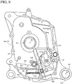
- the first case half 29a of the crankcase 29 is equipped with a scavenge pump 121 that recovers the oil in the crank chamber 41.
- the scavenge pump 121 includes a pump cover (hereinafter referred to as "the scavenge cover") 123 that defines a pump chamber 122 with the first case half 29a.
- the scavenge pump 121 is a trochoid pump. Accordingly, the pump chamber 122 is formed as the space of a circular column whose center axis Mx is parallel to the rotation axis Rx of the crankshaft 42.
- the pump chamber 122 rotatably houses an outer rotor whose cylindrical surface is slidably in contact with the inner circumferential surface of the circular column.
- the outer rotor accommodates an inner rotor that rotates about a rotation axis Dx eccentric from the center axis Mx of the pump chamber 122.
- the outer rotor and the inner rotor may be similar to those of a general trochoid pump.
- the scavenge cover 123 forms a suction passage (hereinafter referred to as "the scavenge suction passage") 124 that extends from the suction port 122a of the pump chamber 122 and is open at the crank chamber 41.
- a drive shaft 125 coaxial to the rotation axis Dx is fixed to the inner rotor. According to the rotation of the drive shaft 125, the inner rotor and the outer rotor rotate while meshing with each other. Outside the scavenge cover 123, a sprocket 126 is fixed to the drive shaft 125.
- a drive chain 128 is wrapped around the sprocket 126 and the sprocket 127 of the crankshaft 42. The drive chain 128 transmits the rotational drive force of the crankshaft 42 from the crankshaft 42 to the drive shaft 125. As the drive shaft 125 rotates, the oil is drawn into the scavenge pump 121 from the crank chamber 41.
- the scavenge pump 121 includes a discharge port 122b that is oriented upward and opposed to the inner wall 129 of the crankcase 29.
- the inner wall 129 includes a partition wall 132 that extends upward from an outer wall 131 that defines the first water channel 112.
- a partition wall 132 defines an oil reservoir space 133 that is continuous from the cam chain chamber 82.
- the inner wall 129 have a plurality of (at least one) ribs 134 opposed to the discharge port 122b of the scavenge pump 121.
- the oil chamber 135 is separated from the crank chamber 41 and defined between the first case half 29a and the second case half 29b below the crank chamber 41.
- the crank chamber 41 is surrounded by a surrounding wall 137 that is coaxial to the rotation axis Rx of the crankshaft 42 and extends along a virtual cylindrical plane that circumscribes the track of the crankshaft 42.
- an oil reservoir 138 is connected at the lowermost position in the gravity direction.
- the oil reservoir 138 is partitioned by a bottom wall 139, which is inclined frontward.
- a scavenge suction passage 124 is open. The oil in the crank chamber 41 is gathered into the oil reservoir 138 by gravity and efficiently drawn into the scavenge pump 121.
- the scavenge discharge port 122b is open at a position higher than the scavenge suction passage 124.
- the falling distance increases.
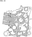
- an introduction port 141 for the oil is formed along the bottom of the oil chamber 135.
- a passage wall 142 is disposed in the oil chamber 135.
- the passage wall 142 includes a plurality of oil channels 143a, 143b, 143c that extend parallel to the rotation axis Rx of the crankshaft 42 at the first case half 29a and the second case half 29b coupled to each other.
- the oil channels include: a first oil channel 143a that is continuous to a flow-in port 144 of an oil filter removably mounted on the outer side of the second case half 29b; a second oil channel 143b that is continuous to a flow-out port 145 of the oil filter; and a third oil channel 143c that is connected to the second oil channel 143b by a connection path 146.
- the third oil channel 143c is connected to: a linear longitudinal oil channel 147a formed in the first case half 29a and connected to the first sliding bearing 43a; and a linear longitudinal oil channel 147b formed in the second case half 29b and connected to the second sliding bearing 43b.
- the oil purified by the oil filter passes through the second oil channel 143b and the third oil channel 143c, to flow into the first sliding bearing 43a and the second sliding bearing 43b.
- the second case half 29b includes, in addition to the longitudinal oil channel 147b and the third oil channel 143c connected to the second sliding bearing 43b of the crankshaft 42, a lateral oil channel 151 that linearly extends from an oil channel 148 around the second sliding bearing 43b to reach the interface 104 between the crankcase 29 and the cylinder block 31.
- the cylinder block 31 includes a supply path that is connected to the lateral oil channel 151 at the interface 104 between the crankcase 29 and the cylinder block 31 and connected to the oil channel of the camshaft 78.
- the oil channel between the lateral oil channel 151 and the supply path penetrates through the gasket 105.
- the passage wall 142 forms, in the oil chamber 135; a first guide channel 152a that passes behind the passage wall 142 to reach the introduction port 141; and a second guide channel 152b that is separated by the passage wall 142 from the first guide channel 152a and passes ahead the passage wall 142 to reach the introduction port 141.
- What is disposed in the first guide channel 152a is a partition wall 155 that extends in the horizontal direction in the oil chamber 135 to divide the oil chamber 135 into a first channel space 153 on the upper side and a second channel space 154 on the lower side.
- the first channel space 153 corresponds to the space surrounded by a bottom wall of the crank chamber 41 and the partition wall 155.
- the second channel space 154 corresponds to the space surrounded by the bottom wall of the crankcase 29 and the partition wall 155.
- the partition wall 155 includes at least one communication hole 156 continuous from the first channel space 153 to the second channel space 154.
- the partition wall 155 enters the generator chamber 47 to divide the space in the generator chamber 47.
- an introduction chamber 157 that is open by an introduction port 141 is defined.
- a filter 159 is disposed in the introduction chamber 157.
- the filter 159 is opposed to the partition wall 155 from below to define a clean chamber 158 with the partition wall 155.
- the oil in the oil chamber 135 flows from the introduction port 141 into the introduction chamber 157 to be filtered by the filter 159.
- the oil then flows into the clean chamber 158.
- the first case half 29a includes a first opening 161, a second opening 162, a third opening 163, and a fourth opening 164 that spatially connect the generator chamber 47 to the oil chamber 135.
- the first opening 161 and the second opening 162 are disposed in the second guide channel 152b.
- the third opening 163 is disposed above the partition wall 155.
- the third opening 163 is elongated in the front-rear direction along the partition wall 155.
- the fourth opening 164 is disposed below the partition wall 155.
- the generator chamber 47 includes a small hole 165 that connects the lower space to the upper space of the partition wall 155.
- the oil that flows from the first opening 161 and the second opening 162 into the generator chamber 47 flows from the small hole 165 and the fourth opening 164 along the partition wall 155.
- the oil flows from the fourth opening 164 into the first guide channel 152a in the oil chamber 135.
- the crankcase 29 includes a link boss 167 that rotatably holds a shaft element 166 about a swing axis Sx parallel to the rotation axis of the rear wheel WR and couples the crankcase 29 to the vehicle body frame 12.
- the shaft element 166 is coupled to the link 25.
- the link boss 167 is disposed lower than a horizontal plane Hr that is in contact with the crank chamber 41 from below.
- the scavenge pump 121 is disposed between the link boss 167 and the crankshaft 42 as seen in a side view of the vehicle.
- the axis of the drive shaft 125 is at least set to be coaxial to the swing axis Sx and positioned inner than a virtual cylindrical plane Sw that includes the rotation axis Rx of the crankshaft 42.
- the first case half 29a of the crankcase 29 is equipped with a feed pump 168 that supplies oil to the camshaft 78, the hydraulic tensioner 85, the crankshaft 42, the piston jet and others.
- the feed pump 168 is a trochoid pump.
- the feed pump 168 includes a pump body 169 that is overlaid on the outer surface of the first case half 29a and rotatably houses the outer rotor.
- a pump cover (hereinafter referred to as "the feed cover") 171 is coupled to the pump body 169.
- the feed cover 171 functions also as the pump body that includes a suction port and a discharge port.
- the outer rotor accommodates an inner rotor that is coupled to the drive shaft 125 and rotates coaxially to the inner rotor of the scavenge pump 121.
- the outer rotor and the inner rotor may be similar to those of a general trochoid pump.
- the scavenge pump 121 and the feed pump 168 include the shared drive shaft 125.
- a drive shaft 172 coupled to the impeller 109 of the water pump 107 is coaxially coupled. In this manner, the scavenge pump 121, the feed pump 168, and the water pump 107 share the drive shafts.
- the first case half 29a includes a linear suction passage (hereinafter referred to as "the feed suction passage") 173 that is open at the clean chamber 158 and connected to the suction port of the feed pump 168.
- the feed suction passage 173 As the drive shaft 125 rotates, the oil is drawn in from the oil chamber 135 via the feed suction passage 173.
- the discharge port of the feed pump 168 is connected to the first oil channel 143a.
- the oil discharged from the feed pump 168 flows into the oil filter.
- the feed suction passage 173 three-dimensionally crosses the scavenge suction passage 124.
- the feed suction passage 173 and the scavenge suction passage 124 three-dimensionally cross the longitudinal oil channels 147a, 147b.
- the first case half 29a includes, in addition to the longitudinal oil channel 147a and the third oil channel 143c connected to the first sliding bearing 43a of the crankshaft 42, a lateral oil channel 175 that linearly extends from an oil channel 174 around the first sliding bearing 43a to reach the interface 104 between the crankcase 29 and the cylinder block 31.
- the cylinder block 31 includes an oil supply path 176 that is connected to the lateral oil channel 175 at the interface 104 between the crankcase 29 and the cylinder block 31 and connected to the supply path 95 of the hydraulic tensioner 85.
- the oil channel between the lateral oil channel 175 and the oil supply path 176 penetrates through the gasket 105.
- the air-fuel mixture burns in the combustion chamber 76.
- the piston 74 reciprocates in the cylinder block 31.
- the crankshaft 42 rotates about the rotation axis Rx.
- the cylinder block 31 and the cylinder head 32 are heated by the combustion heat and the friction heat.
- the rotational drive force of the crankshaft 42 is transmitted to the drive shaft 172 of the water pump 107 via the drive chain 128.
- the cooling water flows from the discharge port 111 of the water pump 107 into the water jackets 106a, 106b via the first water channel 112 and the second water channel 113.
- the cooling water absorbs the thermal energy from the cylinder block 31 and the cylinder head 32 around the cylinder bore 73.
- the cylinder block 31 and the cylinder head 32 are cooled. Thus, any excessive increase in temperature is avoided.
- the cooling water warmed by the thermal energy flows into the thermostat 114.
- the thermostat 114 feeds the cooling water to the first pipe 116 until the cooling water reaches a prescribed temperature.
- the cooling water flows into the first suction port 115 of the water pump 107 via the first pipe 116.
- the cooling water circulates without access to the radiator 118.
- the engine 27 is prevented from being excessively cooled until its temperature reaches a prescribed temperature.
- the thermostat 114 feeds the cooling water to the third pipe 119.
- the cooling water flows into the radiator 118 via the third pipe 119.
- the radiator 118 releases the thermal energy of the cooling water to the outside air.
- the cooling water becomes cool.
- the cooled cooling water flows into the second suction port 115b of the water pump 107 via the second pipe 117. In this manner, the cooling water circulates via the radiator 118.
- the radiator 118 efficiently suppresses an increase in the temperature of the engine 27 when it exceeds a prescribed temperature.
- the oil chamber 135 stores the engine oil.
- the crankshaft 42 rotates, the drive shaft 125 rotates about the rotation axis Dx.
- the engine oil flows from the introduction port 141 into the introduction chamber 157.
- the engine oil is filtered by the filter 159 and drawn into the feed pump 168 from the feed suction passage 173.
- the feed pump 168 discharges the engine oil to the first oil channel 143a.
- the engine oil is filtered by the oil filter and flows from the second passage 143b into the third passage 143c.
- the engine oil of the third passage 143c flows into the longitudinal oil channel 147a as a first path connected to the first sliding bearing 43a and continuous to the oil supply path 176, and the longitudinal oil channel 147b as a second path connected to the second sliding bearing 43b and continuous to the camshaft 78. From the longitudinal oil channel 147a, the engine oil is supplied to the first sliding bearing 43a. The first sliding bearing 43a is lubricated with the engine oil. The engine oil flows from the first sliding bearing 43a into the crank chamber 41.
- the engine oil further flows from the oil channel 174 around the first sliding bearing 43a into the lateral oil channel 175.
- the engine oil is supplied from the lateral oil channel 175 to the hydraulic tensioner 85 via the oil supply path 176.
- the hydraulic tensioner 85 By the cause of the high pressure chamber 99, the hydraulic tensioner 85 fully secures the tension of the cam chain 81. Any redundant engine oil is released from the hydraulic tensioner 85 into the cam chain chamber 82.
- the engine oil is supplied to the second sliding bearing 143b.
- the second sliding bearing 43b is lubricated by the engine oil.
- the engine oil flows from the second sliding bearing 43b into the crank chamber 41.
- the engine oil further flows from the oil channel 148 around the second sliding bearing 43b into the lateral oil channel 151.
- the engine oil from the lateral oil channel 151 transverses the interface 104 and is supplied to the oil channel of the camshaft 78.
- the bearing of the camshaft 78 and the friction surface of the valve operating cam 78a are lubricated.
- the engine oil is gathered by the surrounding wall 137 of the crank chamber 41 and flows from the lowermost position of the crank chamber 41 into the oil reservoir 138.
- the inner rotor and the outer rotor rotate.
- the engine oil flows from the oil reservoir 138 into the scavenge suction passage 124.
- the generator chamber 47 the engine oil is drawn into the scavenge pump 121 via the suction passage 124.
- the scavenge pump 121 discharges the engine oil from the discharge port 122b toward the generator chamber 47.
- the engine oil is discharged from the discharge port 122b of the scavenge pump 121 and flows down along the wall in the generator chamber 47.
- the engine oil flows from the first opening 161 and the second opening 162 into the oil chamber 135.
- the engine oil flows into: the first guide channel 152a that passes through the communication hole 156 behind the passage wall 142 to reach the upstream end (the clean chamber 158) of the feed suction passage 173; and the second guide channel 152b that detours the first guide channel 152a ahead the passage wall 142 to reach the upstream end of the feed suction passage 173.
- the engine oil flows from the third opening 163 and the fourth opening 164 into the oil chamber 135.
- the engine oil of the generator chamber 47 merges with the engine oil of the first guide channel 152a.
- the crankcase 29 includes the scavenge suction passage 124 that is open at the crank chamber 41 and connected to the suction port 122a of the scavenge pump 121, and the scavenge discharge port 122b where the engine oil is discharged from the scavenge pump 121 to the oil chamber 135 that is separated from the crank chamber 41 and defined in the crankcase 29 below the crank chamber 41.
- What is disposed in the oil chamber 135 is the partition wall 155 that horizontally extends in the oil chamber 135 to divide the oil chamber 135 into the first channel space 153 on the upper side and the second channel space 154 on the lower side.
- the partition wall 155 includes at least one communication hole 156 continuous from the first channel space 153 to the second channel space 154.
- the engine oil flows downward by gravity.
- the partition wall 155 regulates the flow of the engine oil from the first channel space 153 to the second channel space 154.
- the channel of the engine oil is set to a desired length.
- the channel of a sufficient length facilitates the release of bubbles from the engine oil.
- the feed pump 168 supplies the engine oil of a sufficient amount in response to the release of bubbles.
- the scavenge pump 121 has its discharge port 122b opposed to the inner wall 129 of the crankcase 29.
- the scavenge pump 121 discharges the engine oil toward the inner wall 129 of the crankcase 29.
- the engine oil flows down the wall. This suppresses generation of bubbles.
- the discharge port 122b of the scavenge pump 121 is directed to the crankshaft 42, the engine oil would be agitated by the rotation of the crankshaft 42 and bubbles would be easily generated. If the discharge port 122b of the scavenge pump 121 is directed downward, the engine oil would splash into the surface of the accumulated engine oil and bubbles would be easily generated.
- the crankcase 29 includes: the scavenge suction passage 124 that is open at the crank chamber 41 and connected to the suction port 122a of the scavenge pump 121; the scavenge discharge port 122b where the engine oil is discharged from the scavenge pump 121 to the oil chamber 135; the feed suction passage 173 that is connected to the suction port of the feed pump 168 to draw in the engine oil from the oil chamber 135; and the longitudinal oil channels 147a, 147b and the third oil channel 143c (the feed discharge passages) connected to the discharge port of the feed pump 168 and guiding the engine oil toward the first sliding bearing 43a and the second sliding bearing 43b of the crankshaft 42.
- the feed suction passage 173 three-dimensionally crosses the scavenge suction passage 124.
- the feed suction passage 173 and the scavenge suction passage 124 three-dimensionally cross the longitudinal oil channels 147a, 147b.
- the positioning relationship of the feed suction passage 173, the scavenge suction passage 124, and the longitudinal oil channels 147a, 147b is flexible. Accordingly, the engine oil paths can be effectively designed without being constrained by the positional relationship of the feed suction passage 173, the scavenge suction passage 124, and the longitudinal oil channels 147a, 147b.
- the engine 27 further includes the water pump 107 that includes the drive shaft 172 coupled to the drive shaft 125 of the scavenge pump 121 and the feed pump 168. That is, the water pump 107 shares the drive shaft with the scavenge pump 121 and the feed pump 168.
- the water pump 107 causes the cooling water to flow, to contribute to cooling the engine oil. Since the scavenge pump 121, the feed pump 168, and the water pump 107 share the drive shafts 125, 172, the number of components is reduced. The space efficiency improves.
- the oil chamber 135 includes the first guide channel 152a that passes through the communication hole 156 to reach the upstream end of the feed suction passage 173, and the second guide channel 152b that detours the first guide channel 152a to reach the upstream end of the feed suction passage 173.
- the first guide channel 152a and the second guide channel 152b forming branches provides a sufficient length from the scavenge discharge passage 136 to the feed suction passage 173.
- the channel of a sufficient length facilitates the release of bubbles from the engine oil.
- the feed pump 168 supplies the engine oil of a sufficient amount in response to the release of bubbles.
- the engine 27 further includes a third guide channel that is continuous from the second guide channel 152b to the first channel space 153. This provides a fully added length from the second guide channel 152b to the feed suction passage 173. The channel of a sufficient length facilitates the release of bubbles from the engine oil.
- the feed pump 168 supplies the engine oil of a sufficient amount in response to the release of bubbles.
- the engine 27 includes the filter 159 that is opposed to the partition wall 155 from below to define the clean chamber 158 with the partition wall 155.
- the clean chamber 158 is connected to the entrance of the feed suction passage 173.
- the engine oil flowing into the feed suction passage 173 is purified by the filter 159.
Description
- The present invention relates to a saddled vehicle including: a vehicle body frame; a crankcase defining a crank chamber for housing a counterweight of a crankshaft, the crankcase being coupled to the vehicle body frame to swing about a swing axis; a swing element coupled to the crankcase and rotatably holding a rear wheel; and a scavenge pump fixed to the crankcase and recovering oil in the crank chamber.
-
JP 2018 - 075 975 A -
EP 3 321 480 A1 discloses a saddled vehicle with a vehicle body frame, a crankcase, a scavenge pump with a suction passage and a scavenge discharge port. - In this structure, the oil is discharged upward from the scavenge pump and hits the inner wall of the crankcase, to flow down the inner wall of the crankcase and directly flow into an oil reservoir. At the oil reservoir, a suction passage continuous to a suction port of the feed pump is open. Since the distance from the discharge port of the scavenge pump to the suction passage is short, bubbles may remain in the oil. The bubbles in the oil reduce the pressure of the oil discharged from the feed pump.
- The present invention has been made in view of the foregoing, and an object thereof is to provide a saddled vehicle equipped with a crankcase where release of bubbles from oil is facilitated.
- According to a first aspect of the present invention, a saddled vehicle includes: a vehicle body frame; a crankcase that defines a crank chamber for housing a counterweight of a crankshaft, the crankcase being coupled to the vehicle body frame to swing about a swing axis; a swing element that is coupled to the crankcase and rotatably holds a rear wheel; a scavenge pump that is fixed to the crankcase and recovers oil in the crank chamber; a scavenge suction passage that is open at the crank chamber and connected to a suction port of the scavenge pump; and a scavenge discharge port where the oil is discharged from the scavenge pump into an oil chamber that is separated from the crank chamber and provided in the crankcase below the crank chamber. The oil chamber includes a partition wall that laterally partitions the oil chamber to divide the oil chamber into a first channel space on an upper side and a second channel space on a lower side. The partition wall includes at least one communication hole that is continuous from the first channel space to the second channel space and that allows the oil to flow from the first channel space to the second channel space.
- According to a second aspect, in addition to the configuration of the first aspect, the scavenge pump has its discharge port opposed to an inner wall of the crankcase.
- According to a third aspect, in addition to the configuration of the first or second aspect, the saddled vehicle further includes a feed suction passage connected to a suction port of a feed pump and draws in the oil from the oil chamber, and a feed discharge passage that is connected to a discharge port of the feed pump and guides the oil toward bearing of the crankshaft. At least two out of the scavenge suction passage, the feed suction passage, and the feed discharge passage three-dimensionally cross each other.
- According to a fourth aspect, in addition to the configuration of the third aspect, the saddled vehicle further includes a water pump that shares a drive shaft with the scavenge pump and the feed pump.
- According to a fifth aspect, in addition to the configuration of the third or fourth aspect, the saddled vehicle further includes a first guide channel that passes through the communication hole to reach an upstream end of the feed suction passage, and a second guide channel that detours the first guide channel to reach the upstream end of the feed suction passage.
- According to a sixth aspect, in addition to the configuration of any one of the third to fifth aspects, the saddled vehicle further includes a filter that is opposed to the partition wall from below to define space with the partition wall, the space being connected to an entrance of the feed suction passage.
- According to the first aspect, in the oil chamber, the oil flows downward by gravity. The partition wall regulates the flow of the oil from the first channel space to the second channel space. By adjusting the position of the communication hole, the channel of the oil is set to a desired length. The channel of a sufficient length facilitates release of bubbles in the oil. The feed pump supplies the oil of a sufficient amount in response to the release of bubbles.
- According to the second aspect, the scavenge pump discharges the oil toward the inner wall of the crankcase. The oil flows down the wall. This suppresses generation of bubbles. On the other hand, if the discharge port of the scavenge pump is directed to the crankshaft, the oil would be agitated by the rotation of the crankshaft and bubbles would be easily generated. If the discharge port of the scavenge pump is directed downward, the oil would splash into the surface of the accumulated oil and bubbles would be easily generated.
- According to the third aspect, the positioning relationship of the scavenge suction passage, the feed suction passage, and the feed discharge passage is flexible. Accordingly, the oil paths can be effectively designed without being constrained by the positional relationship of the scavenge suction passage, the feed suction passage, and the feed discharge passage.
- According to the fourth aspect, the water pump causes the cooling water to flow, to contribute to cooling the oil. Since the scavenge pump, the feed pump, and the water pump share the drive shaft, the number of components is reduced. The space efficiency improves.
- According to the fifth aspect, the first guide channel and the second guide channel forming branches provides a sufficient length to the feed suction passage. The channel of a sufficient length facilitates the release of bubbles from the oil. The feed pump supplies the oil of a sufficient amount in response to the release of bubbles.
- According to the sixth aspect, the oil flowing into the feed suction passage is purified by the filter. The wall provided between the crankshaft and the link boss improves solidity between the crankshaft and the link boss.
-
-
FIG. 1 is a schematic side view of the whole saddled vehicle (motorcycle) according to one embodiment of the present invention (a first embodiment). -
FIG. 2 is an enlarged horizontal cross-sectional view of a power unit taken along line 2-2 inFIG. 1 (the first embodiment). -
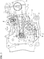
FIG. 3 is a schematic enlarged side view of the structure inside a generator chamber of a crankcase (the first embodiment). -
FIG. 4 is an enlarged sectional view of the range specified by arrow 4 inFIG. 3 (the first embodiment). -
FIG. 5 is an enlarged side view of an engine (the first embodiment). -
FIG. 6 is a schematic enlarged side view of the structure of the inner surface of a first case half (the first embodiment). -
FIG. 7 is a schematic enlarged side view of the structure of the inner surface of a second case half coupled to the first case half (the first embodiment). -
FIG. 8 is a schematic enlarged side view of the structure of the outer surface of the first case half (the first embodiment). -
FIG. 9 is an enlarged side view taken along line 9-9 inFIG. 3 including the axes of the drive shafts of a scavenge pump and a feed pump (the first embodiment). -
FIG. 10 is a schematic enlarged vertical cross-sectional view of oil supply paths in the first case half (the first embodiment). -
- 11: saddled vehicle (motorcycle)
- 12: vehicle body frame
- 29: crankcase
- 41: crank chamber
- 42: crankshaft
- 43a: bearing (first sliding bearing)
- 43b: bearing (second sliding bearing)
- 47: part of third guide channel (generator chamber)
- 51: swing element
- 107: water pump
- 121: scavenge pump
- 122a: suction port
- 122b: scavenge discharge port
- 124: scavenge suction passage
- 135: oil chamber
- 147a: feed discharge passage (longitudinal oil channel)
- 147b: feed discharge passage (longitudinal oil channel)
- 152a: first guide channel
- 152b: second guide channel
- 153: first channel space
- 154: second channel space
- 155: partition wall
- 156: communication hole
- 158: space (clean chamber) connected to feed suction passage
- 159: filter
- 161: part of third guide channel (first opening)
- 162: part of third guide channel (second opening)
- 163: part of third guide channel (third opening)
- 164: part of third guide channel (fourth opening)
- 168: feed pump
- 172: drive shaft (of impeller)
- 173: feed suction passage
- Sx: swing axis of (crankcase)
- WR: rear wheel
- In the following, with reference to the accompanying drawings, a description will be given of one embodiment of the present invention. Note that, in the following description, the front, rear, upper, lower, right, and left directions are based on the view of the rider on a motorcycle.
-
FIG. 1 schematically illustrates a scooter-type motorcycle according to one embodiment of a saddled vehicle. Amotorcycle 11 includes avehicle body frame 12 and a vehicle body cover 13 mounted on thevehicle body frame 12. A head pipe of thevehicle body frame 12 holds in a steerable manner a front fork 15, which holds a front wheel WF to be rotatable about anaxle 14, and a rod-like steering handle 16. - On the
vehicle body cover 13, a rider'sseat 17 is mounted above a rear frame. Thevehicle body cover 13 includes: afront cover 18 that covers the head pipe from the front side; aleg shield 19 that is continuous rearward from thefront cover 18; astep floor 21 that is continuous from the lower end of theleg shield 19 and disposed above a main frame between the rider'sseat 17 and the front wheel WF; and arear cover 22 that supports the rider'sseat 17 on the rear frame. - In the space below the
rear cover 22, a unit swing-type power unit 23 is disposed. Thepower unit 23 is coupled, to be swingable in the top-bottom direction, via alink 25 to abracket 24 coupled to the front end of the rear frame. Thepower unit 23 holds by its rear end a rear wheel WR to be rotatable about the horizontal axis. At a point spaced apart from thelink 25 and thebracket 24 and between the rear frame and thepower unit 23, arear cushion unit 26 is disposed. Thepower unit 23 includes a water-cooled single-cylinder engine 27 and atransmission case 28 that is coupled to anengine body 27a of theengine 27 and houses a transmission that transmits the output of theengine 27 to the rear wheel WR. - The
engine body 27a of theengine 27 includes: acrankcase 29 that holds a crankshaft (described later) to be rotatable about the rotation axis; acylinder block 31 coupled to thecrankcase 29; acylinder head 32 coupled to thecylinder block 31; and ahead cover 33 coupled to thecylinder head 32. To thecylinder head 32, anintake device 34 and an exhaust device 35 are connected. Theintake device 34 includes anair cleaner 36 held by thetransmission case 28 to draw in and purifies the outside air and athrottle body 37 as an intake-system component that connects theair cleaner 36 to thecylinder head 32. - In the
throttle body 37, a throttle functions to adjust the flow rate of the purified air supplied from theair cleaner 36. Afuel injection device 38 is mounted on the upper side wall of thecylinder head 32. Thefuel injection device 38 injects fuel into the purified air to form an air-fuel mixture. - The exhaust device 35 includes: an exhaust pipe 39 that extends rearward from the lower side wall of the
cylinder head 32 beneath theengine 27; and an exhaust muffler (not illustrated) that is connected to the downstream end of the exhaust pipe 39 and coupled to thecrankcase 29. - As illustrated in
FIG. 2 , thecrankcase 29 includes afirst case half 29a and asecond case half 29b. Thefirst case half 29a and thesecond case half 29b define a crankchamber 41 in combination. Thecrank chamber 41 houses acounterweight 42a of acrankshaft 42. On thefirst case half 29a, a first slidingbearing 43a is mounted. The first slidingbearing 43a rotatably holds a first journal of thecrankshaft 42. On thesecond case half 29b, a second slidingbearing 43b is mounted. The second slidingbearing 43b rotatably holds a second journal of thecrankshaft 42. - On the outer side of the second sliding
bearing 43b, a packing 44 is mounted on thesecond case half 29b coaxially to thecrankshaft 42. The packing 44 is in contact with the outer circumference of thecrankshaft 42 to seal the interface between thesecond case half 29b and thecrankshaft 42. The packing 44 liquid-tightly seals thecrank chamber 41. - The
crankcase 29 further includes: agenerator cover 45 as a first case cover that is coupled to thefirst case half 29a and covers one end of thecrankshaft 42, which projects outward from the first slidingbearing 43a; and atransmission cover 46 as a second case cover that is coupled to thesecond case half 29b and covers other end of thecrankshaft 42, which projects outward from the second slidingbearing 43b. The generator cover 45 forms agenerator chamber 47 with thefirst case half 29a. - The
generator chamber 47 houses an AC generator (ACG) 48 that is coupled to one end of thecrankshaft 42. The AC generator 48 includes: acylindrical rotor 48a that is fixed to one end of thecrankshaft 42 projecting from the outer surface of thefirst case half 29a; and astator 48b surrounded by therotor 48a and disposed around thecrankshaft 42. Thestator 48b includes a plurality of stator cores that are fixed to thefirst case half 29a and annularly arranged. A coil is wrapped around each stator core. Therotor 48a includes a magnet that runs on an annular track on the radially outer side of the stator cores. The AC generator 48 generates power by relative rotation between therotor 48a and thestator 48b. The AC generator 48 may be used as an ACG starter. - The
second case half 29b rotatably holds anaxle 49 of the rear wheel WR. The transmission cover 46 forms atransmission chamber 52 with thesecond case half 29b. Thetransmission chamber 52 houses a belt-type continuously variable transmission (hereinafter referred to as "the transmission") 54 that transmits rotational drive force from thecrankshaft 42 to the drivenshaft 53 while continuously changing the gear. Thetransmission 54 will be detailed later. Thesecond case half 29b and thetransmission cover 46 form atransmission case 28. - To the
second case half 29b, agear cover 55 that covers one end of a drivenshaft 53 projecting from the second case half 29b to theaxle 49 side of the rear wheel WR is fastened. The gear cover 55 forms agear chamber 56 with thesecond case half 29b. Thegear chamber 56 houses areduction gear mechanism 57 that transmits rotational drive force from the drivenshaft 53 to theaxle 49 of the rear wheel WR at a predetermined reduction ratio. - The
reduction gear mechanism 57 includes: adrive gear 58a fixed to the drivenshaft 53 projecting from thegear chamber 56; afinal gear 58b fixed to theaxle 49 of the rear wheel WR; andidle gears drive gear 58a and thefinal gear 58b. Theidle gears intermediate shaft 59. Thedrive gear 58a meshes with theidle gear 58c and thefinal gear 58b meshes with theidle gear 58d. Thus, the rotation of the drivenshaft 53 is reduced in speed to be transmitted to theaxle 49 of the rear wheel WR. - The
transmission 54 includes: adrive pulley 61 mounted on thecrankshaft 42 projecting from the outer surface of thesecond case half 29b; a drivenpulley 62 mounted on the drivenshaft 53; and a V-belt (drive belt) 63 wrapped around thedrive pulley 61 and the drivenpulley 62. - The
drive pulley 61 includes: a fixedumbrella element 61a that is fixed to thecrankshaft 42 to be incapable of axially displacing and has itsumbrella surface 64a opposed to thesecond case half 29b coaxially to thecrankshaft 42; and amovable umbrella element 61b that is mounted on thecrankshaft 42 to be axially displaceable between the fixedumbrella element 61a and thesecond case half 29b and has itsumbrella surface 64b opposed to theumbrella surface 64a of the fixedumbrella element 61a coaxially to thecrankshaft 42. Theumbrella surface 64a of the fixedumbrella element 61a and theumbrella surface 64b of themovable umbrella element 61b define a belt groove. The V-belt 63 runs on the belt groove. - The
movable umbrella element 61b has its outward surface (the back side of theumbrella surface 64a) opposed to aweight retaining plate 65 fixed to thecrankshaft 42 to be incapable of axially displacing. Between acam surface 66 of themovable umbrella element 61b and theweight retaining plate 65, aroller weight 67 is interposed. Thecam surface 66 becomes far from the fixedumbrella element 61a as it becomes far in the centrifugal direction from the rotation axis Rx of thecrankshaft 42. As thecrankshaft 42 rotates, centrifugal force occurs at theroller weight 67. Theroller weight 67 is displaced in the centrifugal direction by the centrifugal force. As theroller weight 67 is displaced in the centrifugal direction while making rolling contact with thecam surface 66, themovable umbrella element 61b is driven toward the fixedumbrella element 61a. Thus, as thecrankshaft 42 rotates, themovable umbrella element 61b axially shifts toward the fixedumbrella element 61a and the wrapping radius of the V-belt 63 increases. - The driven
pulley 62 includes: aninner cylinder 68 that is cylindrical and coaxial to the drivenshaft 53 and coaxially mounted on the drivenshaft 53; a fixedumbrella element 62a that is fixed to theinner cylinder 68 and has itsumbrella surface 69a opposed to thetransmission cover 46 coaxially to the drivenshaft 53; an outer cylinder 71 that is cylindrical and coaxial to the drivenshaft 53 and coaxially mounted on theinner cylinder 68; and amovable umbrella element 62b that is fixed to the outer cylinder 71 between the fixedumbrella element 62a and thetransmission cover 46 and has itsumbrella surface 69b opposed to theumbrella surface 69a of the fixedumbrella element 62a coaxially to the drivenshaft 53. Theumbrella surface 69a of the fixedumbrella element 62a and theumbrella surface 69b of themovable umbrella element 62b define a belt groove. The V-belt 63 runs on the belt groove. Theinner cylinder 68 is held by the drivenshaft 53 to be relatively displaceable. The outer cylinder 71 is held by theinner cylinder 68 to be relatively displaceable and incapable of axially relatively displacing. According to the axial relative displacement between the outer cylinder 71 and theinner cylinder 68, themovable umbrella element 62b becomes near to or far from the fixedumbrella element 62a, to realize automatic gear change. - A
centrifugal clutch 72 is mounted on the drivenshaft 53. The centrifugal clutch 72 includes aclutch plate 72a fixed to theinner cylinder 68. Ahelical spring 70 is disposed between theclutch plate 72a and themovable umbrella element 62b. Thehelical spring 70 exerts spring force that presses themovable umbrella element 62b against the fixedumbrella element 62a. As the wrapping radius of the V-belt 63 increases on thedrive pulley 61, on the drivenpulley 62, themovable umbrella element 62b becomes far from the fixedumbrella element 62a against the spring force of thehelical spring 70 and the wrapping radius of the V-belt 63 reduces. - The centrifugal clutch 72 includes an
outer plate 72b fixed to the drivenshaft 53. Theouter plate 72b is opposed to theclutch plate 72a. When theclutch plate 72a rotates, theouter plate 72b is coupled to theclutch plate 72a by the centrifugal force. Thus, the rotation of the drivenpulley 62 is transmitted to the drivenshaft 53. When the engine speed exceeds a set speed, the centrifugal clutch 72 establishes the power transmission state. - The
cylinder block 31 is provided with acylinder bore 73. Into the cylinder bore 73, apiston 74 is fitted to be slidable along a cylinder axis C. Thepiston 74 is coupled to the crank of thecrankshaft 42 by a connectingrod 75. The cylinder axis C is slidably inclined frontward upward relative to the horizontal level. Thecylinder block 31 guides the linear reciprocation movement of thepiston 74 along the cylinder axis C. The linear reciprocation movement of thepiston 74 is converted to the rotation movement of thecrankshaft 42. Acombustion chamber 76 is defined between thepiston 74 and thecylinder head 32. - The
engine 27 includes avalvetrain 77 that exerts control on introducing the air-fuel mixture from theintake device 34 toward thecombustion chamber 76 and on discharging the exhaust gas from thecombustion chamber 76 through the exhaust device 35. Thevalvetrain 77 includes acamshaft 78 that is held on thecylinder head 32 to be rotatable about a rotation axis Cx parallel to the rotation axis Rx of thecrankshaft 42. Thecamshaft 78 is brought into contact with the intake valve and an exhaust valve by itsvalve operating cam 78a. - According to the cam profile of the
valve operating cam 78a, the intake valve opens and closes an intake path that is formed at thecylinder head 32 and open at the ceiling surface of thecombustion chamber 76. The intake path is connected to an air path of thethrottle body 37. When the intake valve opens, the air-fuel mixture is introduced into thecombustion chamber 76 from the intake path via theintake device 34. - According to the cam profile of the
valve operating cam 78a, the exhaust valve opens and closes an exhaust path that is formed at thecylinder head 32 and open at the ceiling surface of thecombustion chamber 76. The exhaust path is connected to the exhaust pipe. When the exhaust valve opens, the exhaust gas is discharged from thecombustion chamber 76 toward the exhaust device 35. - The
valvetrain 77 includes acam chain 81 that is wrapped around asprocket 79a coaxially fixed to thecrankshaft 42 and asprocket 79b coaxially fixed to thecamshaft 78. Thecam chain 81 links the opening and closing operations of the intake valve and the exhaust valve to the reciprocation movement of thepiston 74. Thecrankcase 29, thecylinder block 31, and thecylinder head 32 include acam chain chamber 82 for housing thecam chain 81. Thecam chain chamber 82 is spatially connected to thegenerator chamber 47. - As illustrated in
FIG. 3 , thevalvetrain 77 includes: atensioner shoe 84 that is held by thecrankcase 29 to be swingable about aswing shaft 83 extending parallel to the rotation axis Rx of thecrankshaft 42 and slidably in contact with thecam chain 81; and ahydraulic tensioner 85 that is mounted on thecylinder block 31 at a position spaced apart from theswing shaft 83 and generates drive of pressing thetensioner shoe 84 against thecam chain 81. Thehydraulic tensioner 85 maintains the tension of thecam chain 81. - As illustrated in
FIG. 4 , thehydraulic tensioner 85 includes: aplunger 87 that is axially slidably fitted into a throughhole 86; and aninner sleeve 88 that is fitted into theplunger 87 to be incapable of axially relatively displacing. The tip of theplunger 87 projects into thecam chain chamber 82 from the inner end of the throughhole 86. The tip of theplunger 87 is pressed against thetensioner shoe 84 in thecam chain chamber 82. - The through
hole 86 is bored through amount 89 that is formed at thecylinder block 31 and projects from the outer wall of thecam chain chamber 82. Atensioner cap 91 is overlaid on amount surface 89a of themount 89. Themount surface 89a is formed as a plane perpendicular to the center axis Px of theplunger 87. - The
tensioner cap 91 includes astopper 91a that enters the throughhole 86 to regulate the displacement of theinner sleeve 88 in becoming axially far from the tip of theplunger 87. Thestopper 91a closes the outer end of the throughhole 86. Agasket 92 is interposed between themount surface 89a of themount 89 and thetensioner cap 91. Thegasket 92 seals the interface between thecylinder block 31 and thetensioner cap 91 around the throughhole 86. - An
oil chamber 93 is defined in thestopper 91a. Theoil chamber 93 is connected to asupply path 95 by acommunication hole 94a formed at thestopper 91a, and connected to areturn path 96 by acommunication hole 94b formed at thestopper 91a. Thecommunication hole 94a regulates the flow rate of the oil from thesupply path 95 toward theoil chamber 93. Thecommunication hole 94b regulates the flow rate of the oil from theoil chamber 93 to thereturn path 96. Thereturn path 96 is open at thecam chain chamber 82. - Inside the
inner sleeve 88, alow pressure chamber 97 continuous to theoil chamber 93 of thestopper 91a is defined. Thelow pressure chamber 97 is connected to ahigh pressure chamber 99 defined between theinner sleeve 88 and theplunger 87 by apassage hole 98 formed at theinner sleeve 88. In thehigh pressure chamber 99, aspherical element 101 that closes the opening of thepassage hole 98 is disposed. Ahelical spring 102 is disposed between thespherical element 101 and theplunger 87. Thehelical spring 102 exerts spring force of pressing thespherical element 101 against the opening of thepassage hole 98. Aleak clearance 103 is connected to thehigh pressure chamber 99, to extend along the outer surface of theinner sleeve 88 and the outer surface of theplunger 87 and reach thecam chain chamber 82. - As the pressure in the
low pressure chamber 97 rises, thespherical element 101 leaves theinner sleeve 88 against the spring force of thehelical spring 102. The oil flows from thepassage hole 98 into thehigh pressure chamber 99. Thus, the pressure in thehigh pressure chamber 99 rises. When the pressure in thelow pressure chamber 97 reduces, thespherical element 101 closes thepassage hole 98. This maintains the pressure in thehigh pressure chamber 99. So long as the pressure in thehigh pressure chamber 99 is maintained, the pressure in thelow pressure chamber 97 will not exceed the pressure in thehigh pressure chamber 99. Therefore, the oil flowing into thelow pressure chamber 97 is released form thereturn path 96 to thecam chain chamber 82. - As illustrated in
FIG. 3 , thecrankcase 29 and thecylinder block 31 are overlaid on each other by aninterface 104 which is a plane perpendicular to the cylinder axis C. At theinterface 104 between thecrankcase 29 and thecylinder block 31, agasket 105 is interposed. Thegasket 105 seals theinterface 104 between thecrankcase 29 and thecylinder block 31 around the cylinder. - As illustrated in
FIG. 2 , thecylinder block 31 and thecylinder head 32 are provided withwater jackets combustion chamber 76. Thewater jacket 106a in thecylinder block 31 is defined around the cylinder bore 73 along the interface between thecylinder block 31 and thecylinder head 32. Thewater jacket 106b in thecylinder head 32 extends along the ceiling wall of thecombustion chamber 76 continuous to thewater jacket 106a in thecylinder block 31. - As illustrated in
FIG. 5 , awater pump 107 is mounted on thegenerator cover 45. Thewater pump 107 includes apump cover 108 that defines a pump chamber with thegenerator cover 45. The pump chamber houses animpeller 109 that rotates about a rotation axis Dx, which is parallel to the rotation axis Rx of thecrankshaft 42. A discharge port 111 is defined in thegenerator cover 45. The cooling water is discharged from the discharge port 111 according to the rotation of theimpeller 109. - The
first case half 29a of thecrankcase 29 includes a first water channel 112 connected to the discharge port 111. Thecylinder block 31 includes asecond water channel 113 connected to the first water channel 112. Thesecond water channel 113 is connected to thewater jacket 106a in thecylinder block 31. The channel of the cooling water penetrates through thegasket 105 between the first water channel 112 and thesecond water channel 113. In thecylinder head 32, athermostat 114 is connected to thewater jacket 106b. The cooling water flows into thewater jackets second water channel 113. The cooling water absorbs the thermal energy from thecylinder block 31 and thecylinder head 32 around the cylinder bore 73. The cooling water heated by the thermal energy flows into thethermostat 114. - The
pump cover 108 includes afirst suction port 115a and asecond suction port 115b. Thefirst suction port 115a is connected to athermostat 114 by afirst pipe 116. The cooling water flows into thefirst suction port 115a via thefirst pipe 116 from thethermostat 114. - The
second suction port 115b is connected to theradiator 118 by the second pipe 117. The cooling water cooled by theradiator 118 flows into the pump chamber from thesecond suction port 115b. Theradiator 118 is connected to thethermostat 114 by athird pipe 119. The cooling water is introduced into theradiator 118 from thethermostat 114, to be cooled by theradiator 118. Then, the cooling water flows into the pump chamber from thesecond suction port 115b. - The
thermostat 114 feeds cooling water to thefirst pipe 116 until the cooling water reaches a prescribed temperature. The cooling water circulates without access to theradiator 118. Theengine 27 is prevented from being excessively cooled until its temperature reaches the prescribed temperature. - When the temperature of the cooling water exceeds the prescribed temperature, the
thermostat 114 feeds the cooling water to thethird pipe 119. The cooling water is cooled by theradiator 118. Thus, theradiator 118 efficiently suppresses an increase in the temperature of theengine 27 when it exceeds a prescribed temperature. - As illustrated in
FIG. 3 , thefirst case half 29a of thecrankcase 29 is equipped with ascavenge pump 121 that recovers the oil in thecrank chamber 41. Thescavenge pump 121 includes a pump cover (hereinafter referred to as "the scavenge cover") 123 that defines apump chamber 122 with thefirst case half 29a. Thescavenge pump 121 is a trochoid pump. Accordingly, thepump chamber 122 is formed as the space of a circular column whose center axis Mx is parallel to the rotation axis Rx of thecrankshaft 42. - The
pump chamber 122 rotatably houses an outer rotor whose cylindrical surface is slidably in contact with the inner circumferential surface of the circular column. The outer rotor accommodates an inner rotor that rotates about a rotation axis Dx eccentric from the center axis Mx of thepump chamber 122. The outer rotor and the inner rotor may be similar to those of a general trochoid pump. With thefirst case half 29a, thescavenge cover 123 forms a suction passage (hereinafter referred to as "the scavenge suction passage") 124 that extends from the suction port 122a of thepump chamber 122 and is open at thecrank chamber 41. - A
drive shaft 125 coaxial to the rotation axis Dx is fixed to the inner rotor. According to the rotation of thedrive shaft 125, the inner rotor and the outer rotor rotate while meshing with each other. Outside thescavenge cover 123, asprocket 126 is fixed to thedrive shaft 125. Adrive chain 128 is wrapped around thesprocket 126 and thesprocket 127 of thecrankshaft 42. Thedrive chain 128 transmits the rotational drive force of thecrankshaft 42 from thecrankshaft 42 to thedrive shaft 125. As thedrive shaft 125 rotates, the oil is drawn into thescavenge pump 121 from thecrank chamber 41. - The
scavenge pump 121 includes adischarge port 122b that is oriented upward and opposed to theinner wall 129 of thecrankcase 29. Theinner wall 129 includes apartition wall 132 that extends upward from anouter wall 131 that defines the first water channel 112. Apartition wall 132 defines anoil reservoir space 133 that is continuous from thecam chain chamber 82. Theinner wall 129 have a plurality of (at least one)ribs 134 opposed to thedischarge port 122b of thescavenge pump 121. - As illustrated in
FIGS. 6 and7 , theoil chamber 135 is separated from thecrank chamber 41 and defined between thefirst case half 29a and thesecond case half 29b below thecrank chamber 41. Thecrank chamber 41 is surrounded by a surroundingwall 137 that is coaxial to the rotation axis Rx of thecrankshaft 42 and extends along a virtual cylindrical plane that circumscribes the track of thecrankshaft 42. To the crankchamber 41, anoil reservoir 138 is connected at the lowermost position in the gravity direction. Theoil reservoir 138 is partitioned by abottom wall 139, which is inclined frontward. At the front end of theoil reservoir 138, ascavenge suction passage 124 is open. The oil in thecrank chamber 41 is gathered into theoil reservoir 138 by gravity and efficiently drawn into thescavenge pump 121. - As illustrated in
FIG. 3 , in theoil chamber 135, thescavenge discharge port 122b is open at a position higher than thescavenge suction passage 124. In theoil chamber 135, as compared to the configuration where the oil falls from theoil reservoir 138 by gravity, the falling distance increases. In thefirst case half 29a, anintroduction port 141 for the oil is formed along the bottom of theoil chamber 135. - As illustrated in
FIG. 6 , apassage wall 142 is disposed in theoil chamber 135. Thepassage wall 142 includes a plurality ofoil channels crankshaft 42 at thefirst case half 29a and thesecond case half 29b coupled to each other. The oil channels include: afirst oil channel 143a that is continuous to a flow-inport 144 of an oil filter removably mounted on the outer side of thesecond case half 29b; asecond oil channel 143b that is continuous to a flow-outport 145 of the oil filter; and athird oil channel 143c that is connected to thesecond oil channel 143b by aconnection path 146. Thethird oil channel 143c is connected to: a linearlongitudinal oil channel 147a formed in thefirst case half 29a and connected to the first slidingbearing 43a; and a linearlongitudinal oil channel 147b formed in thesecond case half 29b and connected to the second slidingbearing 43b. The oil purified by the oil filter passes through thesecond oil channel 143b and thethird oil channel 143c, to flow into the first slidingbearing 43a and the second slidingbearing 43b. - As illustrated in
FIG. 7 , thesecond case half 29b includes, in addition to thelongitudinal oil channel 147b and thethird oil channel 143c connected to the second sliding bearing 43b of thecrankshaft 42, alateral oil channel 151 that linearly extends from anoil channel 148 around the second sliding bearing 43b to reach theinterface 104 between thecrankcase 29 and thecylinder block 31. Thecylinder block 31 includes a supply path that is connected to thelateral oil channel 151 at theinterface 104 between thecrankcase 29 and thecylinder block 31 and connected to the oil channel of thecamshaft 78. The oil channel between thelateral oil channel 151 and the supply path penetrates through thegasket 105. - The
passage wall 142 forms, in theoil chamber 135; afirst guide channel 152a that passes behind thepassage wall 142 to reach theintroduction port 141; and asecond guide channel 152b that is separated by thepassage wall 142 from thefirst guide channel 152a and passes ahead thepassage wall 142 to reach theintroduction port 141. What is disposed in thefirst guide channel 152a is apartition wall 155 that extends in the horizontal direction in theoil chamber 135 to divide theoil chamber 135 into afirst channel space 153 on the upper side and asecond channel space 154 on the lower side. Thefirst channel space 153 corresponds to the space surrounded by a bottom wall of thecrank chamber 41 and thepartition wall 155. Thesecond channel space 154 corresponds to the space surrounded by the bottom wall of thecrankcase 29 and thepartition wall 155. Thepartition wall 155 includes at least onecommunication hole 156 continuous from thefirst channel space 153 to thesecond channel space 154. - As illustrated in
FIG. 8 , thepartition wall 155 enters thegenerator chamber 47 to divide the space in thegenerator chamber 47. Below thepartition wall 155, between thefirst case half 29a and thegenerator cover 45, anintroduction chamber 157 that is open by anintroduction port 141 is defined. In theintroduction chamber 157, afilter 159 is disposed. Thefilter 159 is opposed to thepartition wall 155 from below to define aclean chamber 158 with thepartition wall 155. The oil in theoil chamber 135 flows from theintroduction port 141 into theintroduction chamber 157 to be filtered by thefilter 159. The oil then flows into theclean chamber 158. - The
first case half 29a includes afirst opening 161, asecond opening 162, athird opening 163, and afourth opening 164 that spatially connect thegenerator chamber 47 to theoil chamber 135. Thefirst opening 161 and thesecond opening 162 are disposed in thesecond guide channel 152b. Thethird opening 163 is disposed above thepartition wall 155. Thethird opening 163 is elongated in the front-rear direction along thepartition wall 155. Thefourth opening 164 is disposed below thepartition wall 155. Thegenerator chamber 47 includes asmall hole 165 that connects the lower space to the upper space of thepartition wall 155. The oil that flows from thefirst opening 161 and thesecond opening 162 into thegenerator chamber 47 flows from thesmall hole 165 and thefourth opening 164 along thepartition wall 155. The oil flows from thefourth opening 164 into thefirst guide channel 152a in theoil chamber 135. - As illustrated in
FIG. 3 , thecrankcase 29 includes alink boss 167 that rotatably holds ashaft element 166 about a swing axis Sx parallel to the rotation axis of the rear wheel WR and couples thecrankcase 29 to thevehicle body frame 12. Theshaft element 166 is coupled to thelink 25. As illustrated inFIG. 6 , thelink boss 167 is disposed lower than a horizontal plane Hr that is in contact with thecrank chamber 41 from below. Thescavenge pump 121 is disposed between thelink boss 167 and thecrankshaft 42 as seen in a side view of the vehicle. The axis of thedrive shaft 125 is at least set to be coaxial to the swing axis Sx and positioned inner than a virtual cylindrical plane Sw that includes the rotation axis Rx of thecrankshaft 42. - As illustrated in
FIG. 9 , thefirst case half 29a of thecrankcase 29 is equipped with afeed pump 168 that supplies oil to thecamshaft 78, thehydraulic tensioner 85, thecrankshaft 42, the piston jet and others. Thefeed pump 168 is a trochoid pump. Thefeed pump 168 includes apump body 169 that is overlaid on the outer surface of thefirst case half 29a and rotatably houses the outer rotor. To thepump body 169, a pump cover (hereinafter referred to as "the feed cover") 171 is coupled. Thefeed cover 171 functions also as the pump body that includes a suction port and a discharge port. - The outer rotor accommodates an inner rotor that is coupled to the
drive shaft 125 and rotates coaxially to the inner rotor of thescavenge pump 121. The outer rotor and the inner rotor may be similar to those of a general trochoid pump. Thescavenge pump 121 and thefeed pump 168 include the shareddrive shaft 125. To thedrive shaft 125, adrive shaft 172 coupled to theimpeller 109 of thewater pump 107 is coaxially coupled. In this manner, thescavenge pump 121, thefeed pump 168, and thewater pump 107 share the drive shafts. - As illustrated in
FIG. 8 , thefirst case half 29a includes a linear suction passage (hereinafter referred to as "the feed suction passage") 173 that is open at theclean chamber 158 and connected to the suction port of thefeed pump 168. As thedrive shaft 125 rotates, the oil is drawn in from theoil chamber 135 via thefeed suction passage 173. The discharge port of thefeed pump 168 is connected to thefirst oil channel 143a. The oil discharged from thefeed pump 168 flows into the oil filter. Thefeed suction passage 173 three-dimensionally crosses thescavenge suction passage 124. Thefeed suction passage 173 and thescavenge suction passage 124 three-dimensionally cross thelongitudinal oil channels - As illustrated in
FIG. 10 , thefirst case half 29a includes, in addition to thelongitudinal oil channel 147a and thethird oil channel 143c connected to the first slidingbearing 43a of thecrankshaft 42, alateral oil channel 175 that linearly extends from anoil channel 174 around the first slidingbearing 43a to reach theinterface 104 between thecrankcase 29 and thecylinder block 31. Thecylinder block 31 includes anoil supply path 176 that is connected to thelateral oil channel 175 at theinterface 104 between thecrankcase 29 and thecylinder block 31 and connected to thesupply path 95 of thehydraulic tensioner 85. The oil channel between thelateral oil channel 175 and theoil supply path 176 penetrates through thegasket 105. - Next, a description will be given of the operation of the motorcycle according to the present embodiment. When the
engine 27 starts, the air-fuel mixture burns in thecombustion chamber 76. Thepiston 74 reciprocates in thecylinder block 31. According to the reciprocation movement of thepiston 74, thecrankshaft 42 rotates about the rotation axis Rx. Thecylinder block 31 and thecylinder head 32 are heated by the combustion heat and the friction heat. - The rotational drive force of the
crankshaft 42 is transmitted to thedrive shaft 172 of thewater pump 107 via thedrive chain 128. As theimpeller 109 rotates, the cooling water flows from the discharge port 111 of thewater pump 107 into thewater jackets second water channel 113. The cooling water absorbs the thermal energy from thecylinder block 31 and thecylinder head 32 around the cylinder bore 73. Thecylinder block 31 and thecylinder head 32 are cooled. Thus, any excessive increase in temperature is avoided. - The cooling water warmed by the thermal energy flows into the
thermostat 114. Thethermostat 114 feeds the cooling water to thefirst pipe 116 until the cooling water reaches a prescribed temperature. The cooling water flows into the first suction port 115 of thewater pump 107 via thefirst pipe 116. The cooling water circulates without access to theradiator 118. Theengine 27 is prevented from being excessively cooled until its temperature reaches a prescribed temperature. - When the temperature of the cooling water exceeds the prescribed temperature, the
thermostat 114 feeds the cooling water to thethird pipe 119. The cooling water flows into theradiator 118 via thethird pipe 119. Theradiator 118 releases the thermal energy of the cooling water to the outside air. The cooling water becomes cool. The cooled cooling water flows into thesecond suction port 115b of thewater pump 107 via the second pipe 117. In this manner, the cooling water circulates via theradiator 118. Thus, theradiator 118 efficiently suppresses an increase in the temperature of theengine 27 when it exceeds a prescribed temperature. - The
oil chamber 135 stores the engine oil. As thecrankshaft 42 rotates, thedrive shaft 125 rotates about the rotation axis Dx. When the inner rotor rotates in thefeed pump 168, according to the rotation of the inner rotor and the outer rotor, the engine oil flows from theintroduction port 141 into theintroduction chamber 157. The engine oil is filtered by thefilter 159 and drawn into thefeed pump 168 from thefeed suction passage 173. Thefeed pump 168 discharges the engine oil to thefirst oil channel 143a. The engine oil is filtered by the oil filter and flows from thesecond passage 143b into thethird passage 143c. - The engine oil of the
third passage 143c flows into thelongitudinal oil channel 147a as a first path connected to the first slidingbearing 43a and continuous to theoil supply path 176, and thelongitudinal oil channel 147b as a second path connected to the second sliding bearing 43b and continuous to thecamshaft 78. From thelongitudinal oil channel 147a, the engine oil is supplied to the first slidingbearing 43a. The first slidingbearing 43a is lubricated with the engine oil. The engine oil flows from the first sliding bearing 43a into thecrank chamber 41. - The engine oil further flows from the
oil channel 174 around the first sliding bearing 43a into thelateral oil channel 175. The engine oil is supplied from thelateral oil channel 175 to thehydraulic tensioner 85 via theoil supply path 176. By the cause of thehigh pressure chamber 99, thehydraulic tensioner 85 fully secures the tension of thecam chain 81. Any redundant engine oil is released from thehydraulic tensioner 85 into thecam chain chamber 82. - From the
longitudinal oil channel 147b, the engine oil is supplied to the second sliding bearing 143b. The second slidingbearing 43b is lubricated by the engine oil. The engine oil flows from the second sliding bearing 43b into thecrank chamber 41. - The engine oil further flows from the
oil channel 148 around the second sliding bearing 43b into thelateral oil channel 151. The engine oil from thelateral oil channel 151 transverses theinterface 104 and is supplied to the oil channel of thecamshaft 78. The bearing of thecamshaft 78 and the friction surface of thevalve operating cam 78a are lubricated. - The engine oil is gathered by the surrounding
wall 137 of thecrank chamber 41 and flows from the lowermost position of thecrank chamber 41 into theoil reservoir 138. In thescavenge pump 121, according to the rotation of thedrive shaft 125, the inner rotor and the outer rotor rotate. The engine oil flows from theoil reservoir 138 into thescavenge suction passage 124. In thegenerator chamber 47, the engine oil is drawn into thescavenge pump 121 via thesuction passage 124. - The
scavenge pump 121 discharges the engine oil from thedischarge port 122b toward thegenerator chamber 47. The engine oil is discharged from thedischarge port 122b of thescavenge pump 121 and flows down along the wall in thegenerator chamber 47. The engine oil flows from thefirst opening 161 and thesecond opening 162 into theoil chamber 135. The engine oil flows into: thefirst guide channel 152a that passes through thecommunication hole 156 behind thepassage wall 142 to reach the upstream end (the clean chamber 158) of thefeed suction passage 173; and thesecond guide channel 152b that detours thefirst guide channel 152a ahead thepassage wall 142 to reach the upstream end of thefeed suction passage 173. Additionally, the engine oil flows from thethird opening 163 and thefourth opening 164 into theoil chamber 135. The engine oil of thegenerator chamber 47 merges with the engine oil of thefirst guide channel 152a. - In the present embodiment, the
crankcase 29 includes thescavenge suction passage 124 that is open at thecrank chamber 41 and connected to the suction port 122a of thescavenge pump 121, and thescavenge discharge port 122b where the engine oil is discharged from thescavenge pump 121 to theoil chamber 135 that is separated from thecrank chamber 41 and defined in thecrankcase 29 below thecrank chamber 41. What is disposed in theoil chamber 135 is thepartition wall 155 that horizontally extends in theoil chamber 135 to divide theoil chamber 135 into thefirst channel space 153 on the upper side and thesecond channel space 154 on the lower side. Thepartition wall 155 includes at least onecommunication hole 156 continuous from thefirst channel space 153 to thesecond channel space 154. In theoil chamber 135, the engine oil flows downward by gravity. Thepartition wall 155 regulates the flow of the engine oil from thefirst channel space 153 to thesecond channel space 154. By adjusting the position of thecommunication hole 156, the channel of the engine oil is set to a desired length. The channel of a sufficient length facilitates the release of bubbles from the engine oil. Thefeed pump 168 supplies the engine oil of a sufficient amount in response to the release of bubbles. - The
scavenge pump 121 has itsdischarge port 122b opposed to theinner wall 129 of thecrankcase 29. Thescavenge pump 121 discharges the engine oil toward theinner wall 129 of thecrankcase 29. The engine oil flows down the wall. This suppresses generation of bubbles. On the other hand, if thedischarge port 122b of thescavenge pump 121 is directed to thecrankshaft 42, the engine oil would be agitated by the rotation of thecrankshaft 42 and bubbles would be easily generated. If thedischarge port 122b of thescavenge pump 121 is directed downward, the engine oil would splash into the surface of the accumulated engine oil and bubbles would be easily generated. - The
crankcase 29 according to the present embodiment includes: thescavenge suction passage 124 that is open at thecrank chamber 41 and connected to the suction port 122a of thescavenge pump 121; thescavenge discharge port 122b where the engine oil is discharged from thescavenge pump 121 to theoil chamber 135; thefeed suction passage 173 that is connected to the suction port of thefeed pump 168 to draw in the engine oil from theoil chamber 135; and thelongitudinal oil channels third oil channel 143c (the feed discharge passages) connected to the discharge port of thefeed pump 168 and guiding the engine oil toward the first slidingbearing 43a and the second sliding bearing 43b of thecrankshaft 42. Here, thefeed suction passage 173 three-dimensionally crosses thescavenge suction passage 124. Thefeed suction passage 173 and thescavenge suction passage 124 three-dimensionally cross thelongitudinal oil channels feed suction passage 173, thescavenge suction passage 124, and thelongitudinal oil channels feed suction passage 173, thescavenge suction passage 124, and thelongitudinal oil channels - The
engine 27 further includes thewater pump 107 that includes thedrive shaft 172 coupled to thedrive shaft 125 of thescavenge pump 121 and thefeed pump 168. That is, thewater pump 107 shares the drive shaft with thescavenge pump 121 and thefeed pump 168. Thewater pump 107 causes the cooling water to flow, to contribute to cooling the engine oil. Since thescavenge pump 121, thefeed pump 168, and thewater pump 107 share thedrive shafts - The
oil chamber 135 includes thefirst guide channel 152a that passes through thecommunication hole 156 to reach the upstream end of thefeed suction passage 173, and thesecond guide channel 152b that detours thefirst guide channel 152a to reach the upstream end of thefeed suction passage 173. Thefirst guide channel 152a and thesecond guide channel 152b forming branches provides a sufficient length from the scavenge discharge passage 136 to thefeed suction passage 173. The channel of a sufficient length facilitates the release of bubbles from the engine oil. Thefeed pump 168 supplies the engine oil of a sufficient amount in response to the release of bubbles. - The
engine 27 according to the present embodiment further includes a third guide channel that is continuous from thesecond guide channel 152b to thefirst channel space 153. This provides a fully added length from thesecond guide channel 152b to thefeed suction passage 173. The channel of a sufficient length facilitates the release of bubbles from the engine oil. Thefeed pump 168 supplies the engine oil of a sufficient amount in response to the release of bubbles. - The
engine 27 includes thefilter 159 that is opposed to thepartition wall 155 from below to define theclean chamber 158 with thepartition wall 155. Theclean chamber 158 is connected to the entrance of thefeed suction passage 173. The engine oil flowing into thefeed suction passage 173 is purified by thefilter 159.
Claims (6)
- A saddled vehicle (11) comprising:a vehicle body frame (12);a crankcase (29) that defines a crank chamber (41) for housing a counterweight (42a) of a crankshaft (42), the crankcase (29) being coupled to the vehicle body frame (12) to swing about a swing axis (Sx);a scavenge pump (121) that is fixed to the crankcase (29) and recovers oil in the crank chamber (41);a scavenge suction passage (124) that is open at the crank chamber (41) and connected to a suction port (122a) of the scavenge pump (121); anda scavenge discharge port (122b) where the oil is discharged from the scavenge pump (121) into an oil chamber (135) that is separated from the crank chamber (41) and provided in the crankcase (29) below the crank chamber (41), characterised in thatthe oil chamber (135) includes a partition wall (155) that laterally partitions the oil chamber (135) to divide the oil chamber (135) into a first channel space (153) on an upper side and a second channel space (154) on a lower side, andthe partition wall (155) includes at least one communication hole (156) that is continuous from the first channel space (153) to the second channel space (154) and that allows the oil to flow from the first channel space (153) to the second channel space (154).
- The saddled vehicle according to claim 1, wherein the scavenge pump (121) has its discharge port (122a) opposed to an inner wall (129) of the crankcase (29).
- The saddled vehicle according to claim 1 or 2, further comprisinga feed suction passage (173) connected to a suction port of a feed pump (168) and draws in the oil from the oil chamber (135), anda feed discharge passage (147a, 147b) that is connected to a discharge port of the feed pump (168) and guides the oil toward bearing (43a, 43b) of the crankshaft (42), whereinat least two out of the scavenge suction passage (124), the feed suction passage (173), and the feed discharge passage (174a, 174b) three-dimensionally cross each other.
- The saddled vehicle according to claim 3, further comprising a water pump (107) that shares a drive shaft (172) with the scavenge pump (121) and the feed pump (168).
- The saddled vehicle according to claim 3 or 4, further comprisinga first guide channel (152a) that passes through the communication hole (156) to reach an upstream end of the feed suction passage (173), anda second guide channel (152b) that detours the first guide channel (152a) to reach the upstream end of the feed suction passage (173).
- The saddled vehicle according to any one of claims 3 to 5, further comprising a filter (159) that is opposed to the partition wall (155) from below to define space (158) with the partition wall (155), the space (158) being connected to an entrance of the feed suction passage (173).
Applications Claiming Priority (2)
| Application Number | Priority Date | Filing Date | Title |
|---|---|---|---|
| JP2018226047 | 2018-11-30 | ||
| PCT/JP2019/046608 WO2020111188A1 (en) | 2018-11-30 | 2019-11-28 | Saddled vehicle |
Publications (3)
| Publication Number | Publication Date |
|---|---|
| EP3889018A1 EP3889018A1 (en) | 2021-10-06 |
| EP3889018A4 EP3889018A4 (en) | 2022-01-05 |
| EP3889018B1 true EP3889018B1 (en) | 2022-12-28 |
Family
ID=70853843
Family Applications (1)
| Application Number | Title | Priority Date | Filing Date |
|---|---|---|---|
| EP19890358.5A Active EP3889018B1 (en) | 2018-11-30 | 2019-11-28 | Saddled vehicle |
Country Status (3)
| Country | Link |
|---|---|
| EP (1) | EP3889018B1 (en) |
| JP (1) | JP7175329B2 (en) |
| WO (1) | WO2020111188A1 (en) |
Families Citing this family (1)
| Publication number | Priority date | Publication date | Assignee | Title |
|---|---|---|---|---|
| JP2022167314A (en) * | 2021-04-23 | 2022-11-04 | ヤマハ発動機株式会社 | Internal combustion engine and saddle-riding type vehicle |
Family Cites Families (13)
| Publication number | Priority date | Publication date | Assignee | Title |
|---|---|---|---|---|
| DE10029844B4 (en) * | 2000-06-16 | 2004-04-15 | Dr.Ing.H.C. F. Porsche Ag | Internal combustion engine, in particular for motorcycles |
| JP3820970B2 (en) * | 2001-11-28 | 2006-09-13 | スズキ株式会社 | Lubricating oil cooling structure for motorcycles |
| JP2008002455A (en) * | 2006-05-26 | 2008-01-10 | Yamaha Marine Co Ltd | Lubricating apparatus for four cycle engine |
| EP1905970B1 (en) * | 2006-09-29 | 2009-11-18 | Honda Motor Co., Ltd | Oil Passage Structure |
| JP2009092043A (en) * | 2007-10-11 | 2009-04-30 | Yamaha Motor Co Ltd | Drysump type four-cycle engine and saddle type vehicle |
| JP5202417B2 (en) * | 2009-03-31 | 2013-06-05 | 本田技研工業株式会社 | Engine oil sump structure |
| JP5480675B2 (en) * | 2010-03-10 | 2014-04-23 | 本田技研工業株式会社 | Case cover structure for internal combustion engine |
| JP5741229B2 (en) * | 2011-06-08 | 2015-07-01 | スズキ株式会社 | Oil lubrication structure of dry sump type engine |
| JP5796460B2 (en) * | 2011-11-08 | 2015-10-21 | スズキ株式会社 | Engine lubrication structure |
| JP6069183B2 (en) * | 2013-12-20 | 2017-02-01 | 本田技研工業株式会社 | Dry sump engine |
| JP6443108B2 (en) * | 2015-02-16 | 2018-12-26 | スズキ株式会社 | Unit swing type engine unit |
| JP6061407B2 (en) * | 2015-03-27 | 2017-01-18 | 本田技研工業株式会社 | Lubricating device for internal combustion engine |
| JP2018075975A (en) * | 2016-11-09 | 2018-05-17 | ヤマハ発動機株式会社 | Saddle-riding type vehicle |
-
2019
- 2019-11-28 JP JP2020557826A patent/JP7175329B2/en active Active
- 2019-11-28 EP EP19890358.5A patent/EP3889018B1/en active Active
- 2019-11-28 WO PCT/JP2019/046608 patent/WO2020111188A1/en active Application Filing
Also Published As
| Publication number | Publication date |
|---|---|
| WO2020111188A1 (en) | 2020-06-04 |
| EP3889018A4 (en) | 2022-01-05 |
| JPWO2020111188A1 (en) | 2021-09-30 |
| JP7175329B2 (en) | 2022-11-18 |
| EP3889018A1 (en) | 2021-10-06 |
Similar Documents
| Publication | Publication Date | Title |
|---|---|---|
| US4836156A (en) | Timing transmission device for an internal combustion engine | |
| US7093569B2 (en) | Power unit for saddle-ride type vehicle | |
| US8202181B2 (en) | Engine | |
| KR100558422B1 (en) | Engine | |
| US7669573B2 (en) | Scooter type vehicle | |
| US7434561B2 (en) | Engine | |
| US20040244761A1 (en) | Lubrication system for an engine | |
| JP4757060B2 (en) | Auxiliary structure of internal combustion engine for motorcycle | |
| US7290514B2 (en) | Valve train lubricating structure in internal combustion engine | |
| US20040244757A1 (en) | Balancer structure for engine | |
| EP3889018B1 (en) | Saddled vehicle | |
| CA2438495C (en) | Engine lubrication system | |
| US6651635B2 (en) | Breather apparatus for four-cycle engine | |
| EP3889017B1 (en) | Saddle type vehicle | |
| US7367293B2 (en) | Four-stroke engine | |
| CN111255539A (en) | Internal combustion engine | |
| CN111255540B (en) | Internal combustion engine | |
| JP7447762B2 (en) | Lubrication structure of power transmission mechanism | |
| EP3690283B1 (en) | Hydraulic tensioner | |
| JP2010071131A (en) | Structure of cooling oil passage in vehicular engine |
Legal Events
| Date | Code | Title | Description |
|---|---|---|---|
| STAA | Information on the status of an ep patent application or granted ep patent |
Free format text: STATUS: THE INTERNATIONAL PUBLICATION HAS BEEN MADE |
|
| STAA | Information on the status of an ep patent application or granted ep patent |
Free format text: STATUS: THE INTERNATIONAL PUBLICATION HAS BEEN MADE |
|
| PUAI | Public reference made under article 153(3) epc to a published international application that has entered the european phase |
Free format text: ORIGINAL CODE: 0009012 |
|
| STAA | Information on the status of an ep patent application or granted ep patent |
Free format text: STATUS: REQUEST FOR EXAMINATION WAS MADE |
|
| 17P | Request for examination filed |
Effective date: 20210512 |
|
| AK | Designated contracting states |
Kind code of ref document: A1 Designated state(s): AL AT BE BG CH CY CZ DE DK EE ES FI FR GB GR HR HU IE IS IT LI LT LU LV MC MK MT NL NO PL PT RO RS SE SI SK SM TR |
|
| REG | Reference to a national code |
Ref country code: DE Ref legal event code: R079 Ref document number: 602019023822 Country of ref document: DE Free format text: PREVIOUS MAIN CLASS: B62J0031000000 Ipc: F01M0001020000 |
|
| A4 | Supplementary search report drawn up and despatched |
Effective date: 20211203 |
|
| RIC1 | Information provided on ipc code assigned before grant |
Ipc: B62J 31/00 20060101ALI20211129BHEP Ipc: F02B 61/02 20060101ALI20211129BHEP Ipc: F01M 11/03 20060101ALI20211129BHEP Ipc: F01M 11/02 20060101ALI20211129BHEP Ipc: F01M 11/00 20060101ALI20211129BHEP Ipc: F01M 1/12 20060101ALI20211129BHEP Ipc: F01M 1/02 20060101AFI20211129BHEP |
|
| DAV | Request for validation of the european patent (deleted) | ||
| DAX | Request for extension of the european patent (deleted) | ||
| GRAP | Despatch of communication of intention to grant a patent |
Free format text: ORIGINAL CODE: EPIDOSNIGR1 |
|
| STAA | Information on the status of an ep patent application or granted ep patent |
Free format text: STATUS: GRANT OF PATENT IS INTENDED |
|
| INTG | Intention to grant announced |
Effective date: 20220824 |
|
| GRAS | Grant fee paid |
Free format text: ORIGINAL CODE: EPIDOSNIGR3 |
|
| GRAA | (expected) grant |
Free format text: ORIGINAL CODE: 0009210 |
|
| STAA | Information on the status of an ep patent application or granted ep patent |
Free format text: STATUS: THE PATENT HAS BEEN GRANTED |
|
| AK | Designated contracting states |
Kind code of ref document: B1 Designated state(s): AL AT BE BG CH CY CZ DE DK EE ES FI FR GB GR HR HU IE IS IT LI LT LU LV MC MK MT NL NO PL PT RO RS SE SI SK SM TR |
|
| REG | Reference to a national code |
Ref country code: GB Ref legal event code: FG4D |
|
| REG | Reference to a national code |
Ref country code: CH Ref legal event code: EP |
|
| REG | Reference to a national code |
Ref country code: DE Ref legal event code: R096 Ref document number: 602019023822 Country of ref document: DE |
|
| REG | Reference to a national code |
Ref country code: AT Ref legal event code: REF Ref document number: 1540626 Country of ref document: AT Kind code of ref document: T Effective date: 20230115 |
|
| REG | Reference to a national code |
Ref country code: IE Ref legal event code: FG4D |
|
| REG | Reference to a national code |
Ref country code: LT Ref legal event code: MG9D |
|
| PG25 | Lapsed in a contracting state [announced via postgrant information from national office to epo] |
Ref country code: SE Free format text: LAPSE BECAUSE OF FAILURE TO SUBMIT A TRANSLATION OF THE DESCRIPTION OR TO PAY THE FEE WITHIN THE PRESCRIBED TIME-LIMIT Effective date: 20221228 Ref country code: NO Free format text: LAPSE BECAUSE OF FAILURE TO SUBMIT A TRANSLATION OF THE DESCRIPTION OR TO PAY THE FEE WITHIN THE PRESCRIBED TIME-LIMIT Effective date: 20230328 Ref country code: LT Free format text: LAPSE BECAUSE OF FAILURE TO SUBMIT A TRANSLATION OF THE DESCRIPTION OR TO PAY THE FEE WITHIN THE PRESCRIBED TIME-LIMIT Effective date: 20221228 Ref country code: FI Free format text: LAPSE BECAUSE OF FAILURE TO SUBMIT A TRANSLATION OF THE DESCRIPTION OR TO PAY THE FEE WITHIN THE PRESCRIBED TIME-LIMIT Effective date: 20221228 |
|
| REG | Reference to a national code |
Ref country code: NL Ref legal event code: MP Effective date: 20221228 |
|
| REG | Reference to a national code |
Ref country code: AT Ref legal event code: MK05 Ref document number: 1540626 Country of ref document: AT Kind code of ref document: T Effective date: 20221228 |
|
| PG25 | Lapsed in a contracting state [announced via postgrant information from national office to epo] |
Ref country code: RS Free format text: LAPSE BECAUSE OF FAILURE TO SUBMIT A TRANSLATION OF THE DESCRIPTION OR TO PAY THE FEE WITHIN THE PRESCRIBED TIME-LIMIT Effective date: 20221228 Ref country code: LV Free format text: LAPSE BECAUSE OF FAILURE TO SUBMIT A TRANSLATION OF THE DESCRIPTION OR TO PAY THE FEE WITHIN THE PRESCRIBED TIME-LIMIT Effective date: 20221228 Ref country code: HR Free format text: LAPSE BECAUSE OF FAILURE TO SUBMIT A TRANSLATION OF THE DESCRIPTION OR TO PAY THE FEE WITHIN THE PRESCRIBED TIME-LIMIT Effective date: 20221228 Ref country code: GR Free format text: LAPSE BECAUSE OF FAILURE TO SUBMIT A TRANSLATION OF THE DESCRIPTION OR TO PAY THE FEE WITHIN THE PRESCRIBED TIME-LIMIT Effective date: 20230329 |
|
| PG25 | Lapsed in a contracting state [announced via postgrant information from national office to epo] |
Ref country code: NL Free format text: LAPSE BECAUSE OF FAILURE TO SUBMIT A TRANSLATION OF THE DESCRIPTION OR TO PAY THE FEE WITHIN THE PRESCRIBED TIME-LIMIT Effective date: 20221228 |
|
| PG25 | Lapsed in a contracting state [announced via postgrant information from national office to epo] |
Ref country code: SM Free format text: LAPSE BECAUSE OF FAILURE TO SUBMIT A TRANSLATION OF THE DESCRIPTION OR TO PAY THE FEE WITHIN THE PRESCRIBED TIME-LIMIT Effective date: 20221228 Ref country code: RO Free format text: LAPSE BECAUSE OF FAILURE TO SUBMIT A TRANSLATION OF THE DESCRIPTION OR TO PAY THE FEE WITHIN THE PRESCRIBED TIME-LIMIT Effective date: 20221228 Ref country code: PT Free format text: LAPSE BECAUSE OF FAILURE TO SUBMIT A TRANSLATION OF THE DESCRIPTION OR TO PAY THE FEE WITHIN THE PRESCRIBED TIME-LIMIT Effective date: 20230428 Ref country code: ES Free format text: LAPSE BECAUSE OF FAILURE TO SUBMIT A TRANSLATION OF THE DESCRIPTION OR TO PAY THE FEE WITHIN THE PRESCRIBED TIME-LIMIT Effective date: 20221228 Ref country code: EE Free format text: LAPSE BECAUSE OF FAILURE TO SUBMIT A TRANSLATION OF THE DESCRIPTION OR TO PAY THE FEE WITHIN THE PRESCRIBED TIME-LIMIT Effective date: 20221228 Ref country code: CZ Free format text: LAPSE BECAUSE OF FAILURE TO SUBMIT A TRANSLATION OF THE DESCRIPTION OR TO PAY THE FEE WITHIN THE PRESCRIBED TIME-LIMIT Effective date: 20221228 Ref country code: AT Free format text: LAPSE BECAUSE OF FAILURE TO SUBMIT A TRANSLATION OF THE DESCRIPTION OR TO PAY THE FEE WITHIN THE PRESCRIBED TIME-LIMIT Effective date: 20221228 |
|
| PG25 | Lapsed in a contracting state [announced via postgrant information from national office to epo] |
Ref country code: SK Free format text: LAPSE BECAUSE OF FAILURE TO SUBMIT A TRANSLATION OF THE DESCRIPTION OR TO PAY THE FEE WITHIN THE PRESCRIBED TIME-LIMIT Effective date: 20221228 Ref country code: PL Free format text: LAPSE BECAUSE OF FAILURE TO SUBMIT A TRANSLATION OF THE DESCRIPTION OR TO PAY THE FEE WITHIN THE PRESCRIBED TIME-LIMIT Effective date: 20221228 Ref country code: IS Free format text: LAPSE BECAUSE OF FAILURE TO SUBMIT A TRANSLATION OF THE DESCRIPTION OR TO PAY THE FEE WITHIN THE PRESCRIBED TIME-LIMIT Effective date: 20230428 Ref country code: AL Free format text: LAPSE BECAUSE OF FAILURE TO SUBMIT A TRANSLATION OF THE DESCRIPTION OR TO PAY THE FEE WITHIN THE PRESCRIBED TIME-LIMIT Effective date: 20221228 |
|
| REG | Reference to a national code |
Ref country code: DE Ref legal event code: R097 Ref document number: 602019023822 Country of ref document: DE |
|
| PG25 | Lapsed in a contracting state [announced via postgrant information from national office to epo] |
Ref country code: DK Free format text: LAPSE BECAUSE OF FAILURE TO SUBMIT A TRANSLATION OF THE DESCRIPTION OR TO PAY THE FEE WITHIN THE PRESCRIBED TIME-LIMIT Effective date: 20221228 |
|
| PLBE | No opposition filed within time limit |
Free format text: ORIGINAL CODE: 0009261 |
|
| STAA | Information on the status of an ep patent application or granted ep patent |
Free format text: STATUS: NO OPPOSITION FILED WITHIN TIME LIMIT |
|
| 26N | No opposition filed |
Effective date: 20230929 |
|
| PG25 | Lapsed in a contracting state [announced via postgrant information from national office to epo] |
Ref country code: SI Free format text: LAPSE BECAUSE OF FAILURE TO SUBMIT A TRANSLATION OF THE DESCRIPTION OR TO PAY THE FEE WITHIN THE PRESCRIBED TIME-LIMIT Effective date: 20221228 |
|
| PGFP | Annual fee paid to national office [announced via postgrant information from national office to epo] |
Ref country code: IT Payment date: 20231010 Year of fee payment: 5 |