EP3888980A1 - Side airbag device - Google Patents
Side airbag device Download PDFInfo
- Publication number
- EP3888980A1 EP3888980A1 EP21165452.0A EP21165452A EP3888980A1 EP 3888980 A1 EP3888980 A1 EP 3888980A1 EP 21165452 A EP21165452 A EP 21165452A EP 3888980 A1 EP3888980 A1 EP 3888980A1
- Authority
- EP
- European Patent Office
- Prior art keywords
- airbag
- vehicle
- occupant
- console box
- protection portion
- Prior art date
- Legal status (The legal status is an assumption and is not a legal conclusion. Google has not performed a legal analysis and makes no representation as to the accuracy of the status listed.)
- Granted
Links
Images

Classifications
-
- B—PERFORMING OPERATIONS; TRANSPORTING
- B60—VEHICLES IN GENERAL
- B60R—VEHICLES, VEHICLE FITTINGS, OR VEHICLE PARTS, NOT OTHERWISE PROVIDED FOR
- B60R21/00—Arrangements or fittings on vehicles for protecting or preventing injuries to occupants or pedestrians in case of accidents or other traffic risks
- B60R21/02—Occupant safety arrangements or fittings, e.g. crash pads
- B60R21/16—Inflatable occupant restraints or confinements designed to inflate upon impact or impending impact, e.g. air bags
- B60R21/20—Arrangements for storing inflatable members in their non-use or deflated condition; Arrangement or mounting of air bag modules or components
- B60R21/207—Arrangements for storing inflatable members in their non-use or deflated condition; Arrangement or mounting of air bag modules or components in vehicle seats
-
- B—PERFORMING OPERATIONS; TRANSPORTING
- B60—VEHICLES IN GENERAL
- B60R—VEHICLES, VEHICLE FITTINGS, OR VEHICLE PARTS, NOT OTHERWISE PROVIDED FOR
- B60R21/00—Arrangements or fittings on vehicles for protecting or preventing injuries to occupants or pedestrians in case of accidents or other traffic risks
- B60R21/02—Occupant safety arrangements or fittings, e.g. crash pads
- B60R21/16—Inflatable occupant restraints or confinements designed to inflate upon impact or impending impact, e.g. air bags
- B60R21/20—Arrangements for storing inflatable members in their non-use or deflated condition; Arrangement or mounting of air bag modules or components
-
- B—PERFORMING OPERATIONS; TRANSPORTING
- B60—VEHICLES IN GENERAL
- B60R—VEHICLES, VEHICLE FITTINGS, OR VEHICLE PARTS, NOT OTHERWISE PROVIDED FOR
- B60R21/00—Arrangements or fittings on vehicles for protecting or preventing injuries to occupants or pedestrians in case of accidents or other traffic risks
- B60R21/02—Occupant safety arrangements or fittings, e.g. crash pads
- B60R21/16—Inflatable occupant restraints or confinements designed to inflate upon impact or impending impact, e.g. air bags
- B60R21/23—Inflatable members
- B60R21/231—Inflatable members characterised by their shape, construction or spatial configuration
- B60R21/23138—Inflatable members characterised by their shape, construction or spatial configuration specially adapted for side protection
-
- B—PERFORMING OPERATIONS; TRANSPORTING
- B60—VEHICLES IN GENERAL
- B60R—VEHICLES, VEHICLE FITTINGS, OR VEHICLE PARTS, NOT OTHERWISE PROVIDED FOR
- B60R21/00—Arrangements or fittings on vehicles for protecting or preventing injuries to occupants or pedestrians in case of accidents or other traffic risks
- B60R2021/0002—Type of accident
- B60R2021/0006—Lateral collision
-
- B—PERFORMING OPERATIONS; TRANSPORTING
- B60—VEHICLES IN GENERAL
- B60R—VEHICLES, VEHICLE FITTINGS, OR VEHICLE PARTS, NOT OTHERWISE PROVIDED FOR
- B60R21/00—Arrangements or fittings on vehicles for protecting or preventing injuries to occupants or pedestrians in case of accidents or other traffic risks
- B60R2021/003—Arrangements or fittings on vehicles for protecting or preventing injuries to occupants or pedestrians in case of accidents or other traffic risks characterised by occupant or pedestian
- B60R2021/0039—Body parts of the occupant or pedestrian affected by the accident
- B60R2021/0044—Chest
-
- B—PERFORMING OPERATIONS; TRANSPORTING
- B60—VEHICLES IN GENERAL
- B60R—VEHICLES, VEHICLE FITTINGS, OR VEHICLE PARTS, NOT OTHERWISE PROVIDED FOR
- B60R21/00—Arrangements or fittings on vehicles for protecting or preventing injuries to occupants or pedestrians in case of accidents or other traffic risks
- B60R2021/003—Arrangements or fittings on vehicles for protecting or preventing injuries to occupants or pedestrians in case of accidents or other traffic risks characterised by occupant or pedestian
- B60R2021/0039—Body parts of the occupant or pedestrian affected by the accident
- B60R2021/0048—Head
-
- B—PERFORMING OPERATIONS; TRANSPORTING
- B60—VEHICLES IN GENERAL
- B60R—VEHICLES, VEHICLE FITTINGS, OR VEHICLE PARTS, NOT OTHERWISE PROVIDED FOR
- B60R21/00—Arrangements or fittings on vehicles for protecting or preventing injuries to occupants or pedestrians in case of accidents or other traffic risks
- B60R2021/003—Arrangements or fittings on vehicles for protecting or preventing injuries to occupants or pedestrians in case of accidents or other traffic risks characterised by occupant or pedestian
- B60R2021/0039—Body parts of the occupant or pedestrian affected by the accident
- B60R2021/0055—Pelvis
-
- B—PERFORMING OPERATIONS; TRANSPORTING
- B60—VEHICLES IN GENERAL
- B60R—VEHICLES, VEHICLE FITTINGS, OR VEHICLE PARTS, NOT OTHERWISE PROVIDED FOR
- B60R21/00—Arrangements or fittings on vehicles for protecting or preventing injuries to occupants or pedestrians in case of accidents or other traffic risks
- B60R21/02—Occupant safety arrangements or fittings, e.g. crash pads
- B60R21/16—Inflatable occupant restraints or confinements designed to inflate upon impact or impending impact, e.g. air bags
- B60R21/23—Inflatable members
- B60R21/231—Inflatable members characterised by their shape, construction or spatial configuration
- B60R21/23138—Inflatable members characterised by their shape, construction or spatial configuration specially adapted for side protection
- B60R2021/23146—Inflatable members characterised by their shape, construction or spatial configuration specially adapted for side protection seat mounted
-
- B—PERFORMING OPERATIONS; TRANSPORTING
- B60—VEHICLES IN GENERAL
- B60R—VEHICLES, VEHICLE FITTINGS, OR VEHICLE PARTS, NOT OTHERWISE PROVIDED FOR
- B60R21/00—Arrangements or fittings on vehicles for protecting or preventing injuries to occupants or pedestrians in case of accidents or other traffic risks
- B60R21/02—Occupant safety arrangements or fittings, e.g. crash pads
- B60R21/16—Inflatable occupant restraints or confinements designed to inflate upon impact or impending impact, e.g. air bags
- B60R21/23—Inflatable members
- B60R21/231—Inflatable members characterised by their shape, construction or spatial configuration
- B60R2021/23161—Inflatable members characterised by their shape, construction or spatial configuration specially adapted for protecting at least two passengers, e.g. preventing them from hitting each other
Definitions
- the present invention relates to side airbag devices. More specifically, the present invention relates to a side airbag device that inflates and deploys in a space beside an occupant during a lateral collision of a vehicle such as an automobile.
- Patent Literature 1 discloses a vehicle occupant restraint system that can effectively restrict movement of an airbag to an inner side in a vehicle width direction during restraint of an occupant.
- This vehicle occupant restraint system is described to have the sub bag abutted against the console box to restrict the main bag from moving to the inner side in the vehicle width direction when the main bag receives the occupant, thereby restricting movement of the occupant.
- Patent Literature 2 discloses an airbag to assist in keeping an occupant in the correct position during a lateral collision of a vehicle.
- the sub bag in the vehicle occupant restraint system disclosed in Patent Literature 1 is abutted against a corner of the console box.
- the main bag and the sub bag therefore would pivot about the corner of the console box until the top surface of the console box and the sub bag are abutted against each other. It would therefore take some time for the system to stop the movement of the occupant to the inner side in the vehicle width direction, resulting in a large amount of occupant movement.
- An airbag of a conventional side airbag device also tends to inflate and deploy at a shifted position relative to the corner of the console box when the airbag swings due to rapid inflation and deployment, possibly failing to restrict movement of the occupant to the inner side in the vehicle width direction in an early stage.
- the airbag disclosed in Patent Literature 2 can be improved by resolving this issue.
- the present invention was made in response to the above issue, and aims to provide a side airbag device capable of restricting movement of an occupant to an inner side in a vehicle width direction in an early stage.
- a side airbag device including: an inflator configured to generate a gas; and a bag-shaped airbag inflatable and deployable in a space above a console box and beside an occupant seated in a vehicle seat in response to the gas upon activation of the inflator to protect a lateral portion of the occupant, the console box provided on an inner side in a vehicle width direction relative to the vehicle seat, the airbag including a torso protection portion inflatable and deployable in a space beside a torso of the occupant, a support portion provided on a console box side of the torso protection portion and configured to be pushed onto a top surface of the console box in an inflated and deployed state, and a hip protection portion inflatable and deployable between a hip of the occupant and a lateral portion of the console box, the support portion and the hip protection portion being defined by a continuous chamber, the inflator being positioned from above to below the support portion in a side view of the vehicle, the airbag being mounted on a lateral
- the present invention can provide a side airbag device capable of restricting movement of an occupant to an inner side in a vehicle width direction.
- the directions herein are described relative to a vehicle unless otherwise mentioned.
- the "front side” indicates a side based on the forward direction of the vehicle;
- the "rear side” indicates a side based on the backward direction of the vehicle;
- the "upper side” indicates a side based on the upward direction of the vehicle;
- the “lateral side” indicates a side based on the inward direction of a vehicle width direction.
- the arrow FR, the arrow UP, the arrow IN, and the arrow OUT drawn in the figures as appropriate respectively indicate the forward direction of the vehicle, the upward direction of the vehicle, the inward direction of the vehicle width direction, and the outward direction of the vehicle width direction.
- the members placed inside a vehicle seat are illustrated in see-through figures of the vehicle seat.
- FIG. 1 is a schematic side view of a side airbag device of an embodiment before inflation and deployment of an airbag.
- FIG. 2 is a schematic front view of the side airbag device of the embodiment before inflation and deployment of the airbag.
- a side airbag device 1 is mounted on a lateral portion (lateral portion on an inner side in a vehicle width direction) of a seatback (backrest) 31 of a vehicle seat 30.
- the vehicle seat 30 may be a driver's seat or a passenger seat of a vehicle, for example.
- the side airbag device 1 includes an inflator 10 and an airbag 20.
- the inflator 10 is provided inside the airbag 20. Specifically, the whole inflator 10 is provided inside the airbag 20.
- the inflator 10 is a cylindrical (columnar) gas-generating device, and is provided along the extending direction (height direction) of the seatback 31.
- a pair of bolts 10A and 10B protrudes from upper and lower portions of the inflator 10, and this pair of bolts 10A and 10B penetrates the airbag 20.
- the bolts 10A and 10B fix the inflator 10 to the lateral portion (e.g., side frame) of the seatback 31.
- the inflator 10 is activated in a lateral collision of the vehicle. Specifically, first, when an impact sensor mounted on the vehicle detects the lateral collision of the vehicle, the sensor transmits a signal to an electronic control unit (ECU) and the ECU calculates and determines the collision level. If the determined collision level corresponds to a level at which the side airbag 20 should be inflated, the inflator 10 is ignited to generate a gas by a chemical reaction due to combustion. The gas generated in the inflator 10 is then introduced into the airbag 20.
- ECU electronice control unit
- the inflator 10 may be of any type, and may be a pyrotechnic inflator which utilizes a gas generated by combusting a gas-generating agent, a stored gas inflator utilizing a compressed gas, or a hybrid inflator utilizing a gas mixture of a gas generated by combusting a gas-generating agent and a compressed gas, for example.
- the airbag 20 houses the inflator 10.
- the airbag 20 before inflation and deployment is mounted in a folded state on the lateral portion of the vehicle seat 30, which is the lateral portion of the seatback 31 herein, via the inflator 10, and is stored together with a cushion pad while being covered with the outer layer of the seatback 31.
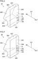
- FIG. 3 is a schematic perspective view showing an example of a deployed state of the airbag in FIG. 2 .
- the airbag 20 has a bag shape.
- the airbag 20 is formed into a three-dimensional bag shape by joining the peripheries of base fabric pieces together.
- the airbag 20 shown in FIG. 3 is prepared by joining the peripheries of a non-occupant side base fabric piece 20A on the inner side in the vehicle width direction, an occupant side base fabric piece 20B on the outer side in the vehicle width direction, middle base fabric pieces 20C on the front and rear sides in the vehicle, and base fabric pieces 20D on the upper and lower sides in the vehicle.
- the non-occupant side base fabric 20A is partly bended along the top surface and side surface of the console box 60.
- the middle base fabric pieces 20C each have a shape extending along the top surface and side surface of the console box 60 in a front-rear view of the vehicle.
- the base fabric piece on the front side in the vehicle preferably has a shape extending along the top surface and side surface of the console box 60 in a front-rear view of the vehicle.
- FIG. 4 is a schematic perspective view showing another example of the deployed state of the airbag in FIG. 2 .
- the base fabric piece on the front side in the vehicle has a shape extending along the top surface and side surface of the console box 60 in a front-rear view of the vehicle.
- the airbag 20 as shown in FIG. 4 can have a more reduced volume than the airbag 20 as shown in FIG. 3 .
- the occupant side base fabric piece 20B of the airbag 20 is provided with an inflator insertion opening 20P through which the inflator 10 is inserted into the airbag 20.
- FIG. 3 and FIG. 4 each show a case where the inflator insertion opening 20P has a slit shape.
- the airbag 20 in a folded state is mounted on the lateral portion of the seatback 31 via the inflator 10, so that the inflator insertion opening 20P comes opposite the seatback 31.
- the inflator insertion opening 20P is closed by the seatback 31 in inflation and deployment of the airbag 20, preventing leakage of a gas from the airbag 20.
- the base fabric pieces used in the airbag 20 may be pieces of cloth formed by weaving yarn such as yarn of nylon 66 or yarn of polyethylene terephthalate.
- the surfaces of the base fabric pieces may be coated with an inorganic substance such as silicon.
- the joining in formation of the base fabric pieces may be performed by any technique, such as sewing, bonding, welding, or any combination thereof.
- a world side impact dummy (World-SID) 40 is seated in the vehicle seat 30.
- the sitting position of the world side impact dummy 40 is in conformity with the side impact test (ECE R95) used in Japan and Europe or the side impact test (FMVSS214) used in the U.S. at present.
- the position and size of an airbag 20 in an inflated and deployed state are determined in accordance with the positions of parts such as a torso 41, a hip 42, a head 43, and an arm 44 of the world side impact dummy 40 shown in FIG. 1 .
- the world side impact dummy 40 is hereinafter referred to as the "occupant 40".
- the vehicle sidewall 50 may be any vehicle part placed on the outer side in the vehicle width direction relative to the occupant 40 seated in the vehicle seat 30 (the side opposing the console box 60), and collectively refers to parts such as side doors, pillars, and side windows.
- the console box 60 is provided on the inner side in the vehicle width direction relative to the vehicle seat 30.
- the console box 60 is provided in the central portion in the vehicle width direction between the driver's seat and the passenger seat.
- the console box 60 may function as an armrest that supports the arm 44 on the inner side in the vehicle width direction of the occupant 40.
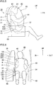
- FIG. 5 is a schematic side view of the side airbag device of the embodiment in an early stage of occupant restraint by the airbag.
- FIG. 6 is a schematic front view of the side airbag device of the embodiment in the early stage of occupant restraint by the airbag.
- the airbag 20 inflates and deploys in a space above the console box 60 and beside the occupant 40 seated in the vehicle seat 30 to protect the lateral portion of the occupant 40.
- the airbag 20 configured to inflate and deploy in this manner is also referred to as a far-side airbag.
- the airbag 20 inflates and deploys to have a torso protection portion 21, a support portion 22, and a hip protection portion 23.
- the torso protection portion 21 inflates and deploys in a space beside the torso 41 of the occupant 40 to come into contact with the torso 41.
- the support portion 22 is provided on the console box 60 side of the torso protection portion 21 and inflates and deploys to come into contact with the top surface of the console box 60.
- the hip protection portion 23 inflates and deploys between the hip 42 of the occupant 40 and the lateral portion of the console box 60.
- the support portion 22 and the hip protection portion 23 preferably extend along the top surface and side surface of the console box 60, respectively, in a front-rear view of the vehicle.
- the middle base fabric piece 20C has a shape extending along the top surface and side surface of the console box 60, and thus the support portion 22 inflates and deploys along the top surface of the console box 60 while keeping in contact with the top surface of the console box 60.
- the hip protection portion 23 inflates and deploys along the side surface of the console box 60 while keeping in contact with the side surface of the console box 60 in a front-rear view of the vehicle.
- the support portion 22 and the hip protection portion 23 are defined by a continuous chamber.
- the expression “parts (here, the support portion 22 and the hip protection portion 23) of the airbag 20 are defined by a continuous chamber” means that no wall partitioning the chamber is provided at the boundary between the parts of the airbag 20 or these parts are not formed using a plurality of bags.
- occurrence of a motion such as distortion between the support portion 22 and the hip protection portion 23 can be prevented as compared to, for example, the case where the hip protection portion 23 is formed by joining bag-shaped sub bags.
- the airbag 20 readily inflates and deploys at the support portion 22 and the hip protection portion 23, restraining the occupant 40 in an early stage.
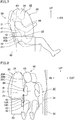
- FIG. 7 is a schematic side view of the side airbag device of the embodiment in a late stage of occupant restraint by the airbag.
- FIG. 8 is a schematic front view of the side airbag device of the embodiment in the late stage of occupant restraint by the airbag.
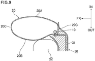
- FIG. 9 is a schematic top view showing a cross section of the vicinity of an inflator in the side airbag device in FIG. 7 and FIG. 8 .
- the hip protection portion 23 is pressed between the hip 42 of the occupant 40 and the lateral portion of the console box 60.
- the inner pressure of the support portion 22 defined by a chamber continuous to the hip protection portion 23 increases. Since the support portion 22 and the hip protection portion 23 are defined by a continuous chamber, the inner pressure of the support portion 22 easily increases when the hip protection portion 23 is pressed.
- the torso protection portion 21 leans toward the inner side in the vehicle width direction when it comes into contact with the torso 41 of the occupant 40 leaning toward the inner side in the vehicle width direction.
- the support portion 22 is immediately pushed onto the top surface of the console box 60, which generates a reaction force from the top surface of the console box 60.
- the inner pressure of the support portion 22 is high as described above, so that the magnitude of reaction force from the top surface of the console box 60 is large.
- the airbag 20 since the support portion 22 and the hip protection portion 23 inflate and deploy along the top surface and side surface of the console box 60, respectively, in a front-rear view of the vehicle, the airbag 20 has a stable deployment behavior without pivoting about the corner of the console box 60. Such a stable deployment behavior of the airbag 20 also contributes to restriction of movement of the occupant 40 to the inner side in the vehicle width direction in an early stage.
- a portion of the support portion 22 and a portion of the hip protection portion 23 respectively opposing the top surface and side surface of the console box 60 are preferably defined by a continuous single base fabric piece.
- the portion of the support portion 22 and the portion of the hip protection portion 23 respectively opposing the top surface and side surface of the console box 60 in an inflated and deployed state are defined by the continuous single base fabric piece 20A.
- the airbag 20 inflates and deploys to have a round shape with large inflation diameters at the portion of the support portion 22 and the portion of the hip protection portion 23 respectively opposing the top surface and side surface of the console box 60.
- the magnitude of reaction force from the top surface and side surface of the console box 60 in the inflated and deployed state increases.
- the airbag 20 torso protection portion 21
- such inflation and deployment of the airbag 20 allow the support portion 22 and the hip protection portion 23 to come into contact with the console box 60 in an early stage.
- the support portion 22 is preferably pushed onto half or more of the top surface of the console box 60 in a front-rear view of the vehicle, more preferably onto the entire top surface of the console box 60 in a front-rear view of the vehicle as shown in FIG. 8 .
- the support portion 22 is pushed onto half or more of the top surface of the console box 60 in an inflated and deployed state, the magnitude of reaction force from the top surface of the console box 60 further increases.
- the airbag 20 torso protection portion 21
- the torso protection portion 21, the support portion 22, and the hip protection portion 23 are defined by a continuous chamber, and in an inflated and deployed state, there is no depression on a portion between an upper end of the torso protection portion 21 and an end on the inner side in the vehicle width direction of the support portion 22 in a front-rear view of the vehicle as shown in FIG. 8 .
- Such a structure prevents the airbag 20 from bending between the torso protection portion 21 and the support portion 22 when the airbag 20 receives the occupant 40. As a result, the airbag 20 can stably receive the occupant 40.
- the airbag 20 may further include a head protection portion 24 as shown in FIG. 8 .
- the head protection portion 24 is provided on the upper side of the torso protection portion 21 and configured to protect the head 43 of the occupant 40. With the head protection portion 24, the airbag 20 can receive the whole body of the occupant 40. As a result, the airbag 20 can efficiently restrict movement of the occupant 40 to the inner side in the vehicle width direction.
- the inflator 10 is housed in the airbag 20, and is positioned from above to below the support portion 22, more specifically from the torso protection portion 21 to the hip protection portion 23, in a side view of the vehicle as shown in FIG. 7 . Also, the bolts 10A and 10B of the inflator 10 are positioned above and below the support portion 22, respectively. This means that the position where the gas is generated and the support portion 22 are relatively close to each other. Thus, when the airbag 20 inflates and deploys in response to the gas generated by the inflator 10, the gas pressure near the support portion 22 during inflation and deployment of the airbag 20 is maintained high, which secures self-supportability of the airbag 20 owing to the support portion 22.
- the torso protection portion 21, the support portion 22, and the hip protection portion 23 therefore do not easily swing even when the airbag 20 swings due to rapid inflation and deployment.
- the inflation and deployment position of the airbag 20 relative to the corner of the console box 60 is not easily shifted, so that the airbag 20 has a stable deployment behavior.
- the airbag 20 restricts movement of the occupant 40 to the inner side in the vehicle width direction in an early stage.
- the airbag 20 is, as shown in FIG. 9 , mounted on the lateral portion of the vehicle seat 30, which is the lateral portion of the seatback 31 herein, via the inflator 10.
- the torso protection portion 21, the support portion 22, and the hip protection portion 23 are fixed to the lateral portion of the vehicle seat 30, which is the lateral portion of the seatback 31 herein, via the inflator 10.
- This further restricts swinging of the support portion 22 near the fixed inflator 10 in the inflated and deployed state of the airbag 20.
- the inflation and deployment position of the airbag 20 relative to the corner of the console box 60 is not easily shifted, so that the airbag 20 has a stable deployment behavior.
- the airbag 20 restricts movement of the occupant 40 to the inner side in the vehicle width direction in an early stage.
- the hip protection portion 23 inflated and deployed between the hip 42 of the occupant 40 and the lateral portion of the console box 60 may be dragged out from the position.
- the hip protection portion 23 is fixed to the lateral portion of the vehicle seat 30, which is the lateral portion of the seatback 31 herein, as described above, the hip protection portion 23 is not easily dragged out and can stably protect the hip 42 of the occupant 40.
- the airbag 20 inflated and deployed in response to the gas generated from the inflator 10 inflates into a shape as round as possible with its inner pressure.
- the portion with the largest size in the vehicle width direction in an inflated and deployed state is positioned on the front side in the vehicle.
- the airbag 20 can more stably protect the occupant 40 by surrounding the occupant 40 between the portion of the airbag 20 with the largest size in the vehicle width direction and the seatback 31.
- the other components of the side airbag device 1 to be used may be similar to components of conventionally known side airbag devices as appropriate.
- the embodiment above describes the case where the inflator 10 is activated when an obstacle collides with a vehicle sidewall opposing the vehicle sidewall 50 in the vehicle width direction.
- the inflator 10 may be activated when an obstacle collides with the vehicle sidewall 50.
- the airbag 20 can restrain the occupant 40 in an early stage.
Landscapes
- Engineering & Computer Science (AREA)
- Mechanical Engineering (AREA)
- Air Bags (AREA)
Abstract
Description
- The present invention relates to side airbag devices. More specifically, the present invention relates to a side airbag device that inflates and deploys in a space beside an occupant during a lateral collision of a vehicle such as an automobile.
- Side airbag devices are known to prevent an occupant, in a lateral collision of a vehicle, from moving to an inner side in a vehicle width direction and coming into contact with an occupant in the next seat.
- For example,
Patent Literature 1 discloses a vehicle occupant restraint system that can effectively restrict movement of an airbag to an inner side in a vehicle width direction during restraint of an occupant. This vehicle occupant restraint system is described to have the sub bag abutted against the console box to restrict the main bag from moving to the inner side in the vehicle width direction when the main bag receives the occupant, thereby restricting movement of the occupant. - Patent Literature 2 discloses an airbag to assist in keeping an occupant in the correct position during a lateral collision of a vehicle.
-
- Patent Literature 1:
JP 2014-108740 A - Patent Literature 2:
WO 2019/228898 - The sub bag in the vehicle occupant restraint system disclosed in
Patent Literature 1 is abutted against a corner of the console box. The main bag and the sub bag therefore would pivot about the corner of the console box until the top surface of the console box and the sub bag are abutted against each other. It would therefore take some time for the system to stop the movement of the occupant to the inner side in the vehicle width direction, resulting in a large amount of occupant movement. - An airbag of a conventional side airbag device also tends to inflate and deploy at a shifted position relative to the corner of the console box when the airbag swings due to rapid inflation and deployment, possibly failing to restrict movement of the occupant to the inner side in the vehicle width direction in an early stage. For example, the airbag disclosed in Patent Literature 2 can be improved by resolving this issue.
- The present invention was made in response to the above issue, and aims to provide a side airbag device capable of restricting movement of an occupant to an inner side in a vehicle width direction in an early stage.
- One aspect of the present invention relates to a side airbag device including: an inflator configured to generate a gas; and a bag-shaped airbag inflatable and deployable in a space above a console box and beside an occupant seated in a vehicle seat in response to the gas upon activation of the inflator to protect a lateral portion of the occupant, the console box provided on an inner side in a vehicle width direction relative to the vehicle seat, the airbag including a torso protection portion inflatable and deployable in a space beside a torso of the occupant, a support portion provided on a console box side of the torso protection portion and configured to be pushed onto a top surface of the console box in an inflated and deployed state, and a hip protection portion inflatable and deployable between a hip of the occupant and a lateral portion of the console box, the support portion and the hip protection portion being defined by a continuous chamber, the inflator being positioned from above to below the support portion in a side view of the vehicle, the airbag being mounted on a lateral portion of the vehicle seat via the inflator.
- The present invention can provide a side airbag device capable of restricting movement of an occupant to an inner side in a vehicle width direction.
-
-
FIG. 1 is a schematic side view of a side airbag device of an embodiment before inflation and deployment of an airbag. -
FIG. 2 is a schematic front view of the side airbag device of the embodiment before inflation and deployment of the airbag. -
FIG. 3 is a schematic perspective view showing an example of a deployed state of the airbag inFIG. 2 . -
FIG. 4 is a schematic perspective view showing another example of the deployed state of the airbag inFIG. 2 . -
FIG. 5 is a schematic side view of the side airbag device of the embodiment in an early stage of occupant restraint by the airbag. -
FIG. 6 is a schematic front view of the side airbag device of the embodiment in the early stage of occupant restraint by the airbag. -
FIG. 7 is a schematic side view of the side airbag device of the embodiment in a late stage of occupant restraint by the airbag. -
FIG. 8 is a schematic front view of the side airbag device of the embodiment in the late stage of occupant restraint by the airbag. -
FIG. 9 is a schematic top view showing a cross section of the vicinity of an inflator in the side airbag device inFIG. 7 and FIG. 8 . - The side airbag device of an embodiment of the present invention is described with reference to the drawings.
- The directions herein are described relative to a vehicle unless otherwise mentioned. For example, the "front side" indicates a side based on the forward direction of the vehicle; the "rear side" indicates a side based on the backward direction of the vehicle; the "upper side" indicates a side based on the upward direction of the vehicle; and the "lateral side" indicates a side based on the inward direction of a vehicle width direction. The arrow FR, the arrow UP, the arrow IN, and the arrow OUT drawn in the figures as appropriate respectively indicate the forward direction of the vehicle, the upward direction of the vehicle, the inward direction of the vehicle width direction, and the outward direction of the vehicle width direction. The members placed inside a vehicle seat are illustrated in see-through figures of the vehicle seat.
-
FIG. 1 is a schematic side view of a side airbag device of an embodiment before inflation and deployment of an airbag.FIG. 2 is a schematic front view of the side airbag device of the embodiment before inflation and deployment of the airbag. - As shown in
FIG. 1 and FIG. 2 , aside airbag device 1 is mounted on a lateral portion (lateral portion on an inner side in a vehicle width direction) of a seatback (backrest) 31 of avehicle seat 30. - The
vehicle seat 30 may be a driver's seat or a passenger seat of a vehicle, for example. - The
side airbag device 1 includes aninflator 10 and anairbag 20. - The
inflator 10 is provided inside theairbag 20. Specifically, thewhole inflator 10 is provided inside theairbag 20. Theinflator 10 is a cylindrical (columnar) gas-generating device, and is provided along the extending direction (height direction) of theseatback 31. A pair ofbolts inflator 10, and this pair ofbolts airbag 20. Thebolts inflator 10 to the lateral portion (e.g., side frame) of theseatback 31. - The
inflator 10 is activated in a lateral collision of the vehicle. Specifically, first, when an impact sensor mounted on the vehicle detects the lateral collision of the vehicle, the sensor transmits a signal to an electronic control unit (ECU) and the ECU calculates and determines the collision level. If the determined collision level corresponds to a level at which theside airbag 20 should be inflated, theinflator 10 is ignited to generate a gas by a chemical reaction due to combustion. The gas generated in theinflator 10 is then introduced into theairbag 20. - The
inflator 10 may be of any type, and may be a pyrotechnic inflator which utilizes a gas generated by combusting a gas-generating agent, a stored gas inflator utilizing a compressed gas, or a hybrid inflator utilizing a gas mixture of a gas generated by combusting a gas-generating agent and a compressed gas, for example. - The
airbag 20 houses theinflator 10. Theairbag 20 before inflation and deployment is mounted in a folded state on the lateral portion of thevehicle seat 30, which is the lateral portion of theseatback 31 herein, via theinflator 10, and is stored together with a cushion pad while being covered with the outer layer of theseatback 31. -
FIG. 3 is a schematic perspective view showing an example of a deployed state of the airbag inFIG. 2 . As shown inFIG. 3 , theairbag 20 has a bag shape. Theairbag 20 is formed into a three-dimensional bag shape by joining the peripheries of base fabric pieces together. Specifically, theairbag 20 shown inFIG. 3 is prepared by joining the peripheries of a non-occupant sidebase fabric piece 20A on the inner side in the vehicle width direction, an occupant sidebase fabric piece 20B on the outer side in the vehicle width direction, middlebase fabric pieces 20C on the front and rear sides in the vehicle, andbase fabric pieces 20D on the upper and lower sides in the vehicle. As is clear from comparison with the later-describedFIG. 6 andFIG. 8 , the non-occupantside base fabric 20A is partly bended along the top surface and side surface of theconsole box 60. The middlebase fabric pieces 20C each have a shape extending along the top surface and side surface of theconsole box 60 in a front-rear view of the vehicle. - Of the base fabric pieces of the
airbag 20 on the front and rear sides in the vehicle, the base fabric piece on the front side in the vehicle preferably has a shape extending along the top surface and side surface of theconsole box 60 in a front-rear view of the vehicle.FIG. 4 is a schematic perspective view showing another example of the deployed state of the airbag inFIG. 2 . Of themiddle fabric pieces 20C of theairbag 20 shown inFIG. 4 on the front and rear sides in the vehicle, the base fabric piece on the front side in the vehicle has a shape extending along the top surface and side surface of theconsole box 60 in a front-rear view of the vehicle. Theairbag 20 as shown inFIG. 4 can have a more reduced volume than theairbag 20 as shown inFIG. 3 . - The occupant side
base fabric piece 20B of theairbag 20 is provided with an inflator insertion opening 20P through which theinflator 10 is inserted into theairbag 20.FIG. 3 and FIG. 4 each show a case where theinflator insertion opening 20P has a slit shape. There are bolt holes above and below theinflator insertion opening 20P, which allow the pair ofbolts airbag 20 from the bolt holes after thewhole inflator 10 is inserted into theairbag 20 through theinflator insertion opening 20P. Then, theairbag 20 in a folded state is mounted on the lateral portion of theseatback 31 via theinflator 10, so that theinflator insertion opening 20P comes opposite theseatback 31. Thereby, theinflator insertion opening 20P is closed by theseatback 31 in inflation and deployment of theairbag 20, preventing leakage of a gas from theairbag 20. - The base fabric pieces used in the
airbag 20 may be pieces of cloth formed by weaving yarn such as yarn of nylon 66 or yarn of polyethylene terephthalate. In order to improve the heat resistance and the airtightness, the surfaces of the base fabric pieces may be coated with an inorganic substance such as silicon. - The joining in formation of the base fabric pieces may be performed by any technique, such as sewing, bonding, welding, or any combination thereof.
- In the present embodiment, a world side impact dummy (World-SID) 40 is seated in the
vehicle seat 30. The sitting position of the worldside impact dummy 40 is in conformity with the side impact test (ECE R95) used in Japan and Europe or the side impact test (FMVSS214) used in the U.S. at present. The position and size of anairbag 20 in an inflated and deployed state are determined in accordance with the positions of parts such as atorso 41, ahip 42, ahead 43, and anarm 44 of the worldside impact dummy 40 shown inFIG. 1 . The worldside impact dummy 40 is hereinafter referred to as the "occupant 40". - The
vehicle sidewall 50 may be any vehicle part placed on the outer side in the vehicle width direction relative to theoccupant 40 seated in the vehicle seat 30 (the side opposing the console box 60), and collectively refers to parts such as side doors, pillars, and side windows. - The
console box 60 is provided on the inner side in the vehicle width direction relative to thevehicle seat 30. For example, theconsole box 60 is provided in the central portion in the vehicle width direction between the driver's seat and the passenger seat. Theconsole box 60 may function as an armrest that supports thearm 44 on the inner side in the vehicle width direction of theoccupant 40. -
FIG. 5 is a schematic side view of the side airbag device of the embodiment in an early stage of occupant restraint by the airbag.FIG. 6 is a schematic front view of the side airbag device of the embodiment in the early stage of occupant restraint by the airbag. - When a vehicle has a lateral collision with an obstacle (e.g., another vehicle), specifically, when an obstacle collides with a vehicle sidewall opposing a
vehicle sidewall 50 in the vehicle width direction (when thevehicle seat 30 is the driver's seat, the vehicle body portion on the outer side in the vehicle width direction relative to the passenger seat) and the inflator 10 is activated, the gas generated by theinflator 10 is introduced into theairbag 20 and theairbag 20 inflates while unfolded. The force applied from theinflated airbag 20 then tears open the outer layer of theseatback 31. Thereby, as shown inFIG. 5 and FIG. 6 , theairbag 20 inflates and deploys in a space above theconsole box 60 and beside theoccupant 40 seated in thevehicle seat 30 to protect the lateral portion of theoccupant 40. Theairbag 20 configured to inflate and deploy in this manner is also referred to as a far-side airbag. - In a lateral collision of the vehicle, the
occupant 40 seated in thevehicle seat 30 leans, while moving, toward the inner side in the vehicle width direction with thehip 42 at the center. Meanwhile, in the lateral collision of the vehicle, theairbag 20 inflates and deploys to have atorso protection portion 21, asupport portion 22, and ahip protection portion 23. When theairbag 20 inflates and deploys, thetorso protection portion 21 inflates and deploys in a space beside thetorso 41 of theoccupant 40 to come into contact with thetorso 41. Thesupport portion 22 is provided on theconsole box 60 side of thetorso protection portion 21 and inflates and deploys to come into contact with the top surface of theconsole box 60. Thehip protection portion 23 inflates and deploys between thehip 42 of theoccupant 40 and the lateral portion of theconsole box 60. - In the inflated and deployed state of the
airbag 20, thesupport portion 22 and thehip protection portion 23 preferably extend along the top surface and side surface of theconsole box 60, respectively, in a front-rear view of the vehicle. For example, in theairbag 20 as shown inFIG. 6 , in a front-rear view of the vehicle, the middlebase fabric piece 20C has a shape extending along the top surface and side surface of theconsole box 60, and thus thesupport portion 22 inflates and deploys along the top surface of theconsole box 60 while keeping in contact with the top surface of theconsole box 60. Thehip protection portion 23 inflates and deploys along the side surface of theconsole box 60 while keeping in contact with the side surface of theconsole box 60 in a front-rear view of the vehicle. - The
support portion 22 and thehip protection portion 23 are defined by a continuous chamber. The expression "parts (here, thesupport portion 22 and the hip protection portion 23) of theairbag 20 are defined by a continuous chamber" means that no wall partitioning the chamber is provided at the boundary between the parts of theairbag 20 or these parts are not formed using a plurality of bags. With thesupport portion 22 and thehip protection portion 23 defined by a continuous chamber, occurrence of a motion such as distortion between thesupport portion 22 and thehip protection portion 23 can be prevented as compared to, for example, the case where thehip protection portion 23 is formed by joining bag-shaped sub bags. As a result, theairbag 20 readily inflates and deploys at thesupport portion 22 and thehip protection portion 23, restraining theoccupant 40 in an early stage. -
FIG. 7 is a schematic side view of the side airbag device of the embodiment in a late stage of occupant restraint by the airbag.FIG. 8 is a schematic front view of the side airbag device of the embodiment in the late stage of occupant restraint by the airbag.FIG. 9 is a schematic top view showing a cross section of the vicinity of an inflator in the side airbag device inFIG. 7 and FIG. 8 . - As the
occupant 40 further moves to the inner side in the vehicle width direction, as shown inFIG. 8 , thehip protection portion 23 is pressed between thehip 42 of theoccupant 40 and the lateral portion of theconsole box 60. When thehip protection portion 23 is pressed, the inner pressure of thesupport portion 22 defined by a chamber continuous to thehip protection portion 23 increases. Since thesupport portion 22 and thehip protection portion 23 are defined by a continuous chamber, the inner pressure of thesupport portion 22 easily increases when thehip protection portion 23 is pressed. - Meanwhile, the
torso protection portion 21 leans toward the inner side in the vehicle width direction when it comes into contact with thetorso 41 of theoccupant 40 leaning toward the inner side in the vehicle width direction. When thetorso protection portion 21 leans toward the inner side in the vehicle width direction, thesupport portion 22 is immediately pushed onto the top surface of theconsole box 60, which generates a reaction force from the top surface of theconsole box 60. At this time, the inner pressure of thesupport portion 22 is high as described above, so that the magnitude of reaction force from the top surface of theconsole box 60 is large. Thus, when this large magnitude of reaction force is applied to thetorso protection portion 21 via thesupport portion 22, the force of thetorso protection portion 21 moving back to the position in the early stage of occupant restraint (to the outer side in the vehicle width direction) works intensely. As a result, theoccupant 40 is restricted from moving to the inner side in the vehicle width direction in an early stage. - Also, as described above, since the
support portion 22 and thehip protection portion 23 inflate and deploy along the top surface and side surface of theconsole box 60, respectively, in a front-rear view of the vehicle, theairbag 20 has a stable deployment behavior without pivoting about the corner of theconsole box 60. Such a stable deployment behavior of theairbag 20 also contributes to restriction of movement of theoccupant 40 to the inner side in the vehicle width direction in an early stage. - In the inflated and deployed state of the
airbag 20, a portion of thesupport portion 22 and a portion of thehip protection portion 23 respectively opposing the top surface and side surface of theconsole box 60 are preferably defined by a continuous single base fabric piece. For example, in theairbag 20 as shown inFIG. 3 and FIG. 4 , the portion of thesupport portion 22 and the portion of thehip protection portion 23 respectively opposing the top surface and side surface of theconsole box 60 in an inflated and deployed state are defined by the continuous singlebase fabric piece 20A. With the portion of thesupport portion 22 and the portion of thehip protection portion 23 respectively opposing the top surface and side surface of theconsole box 60 in the inflated and deployed state being defined by a continuous single base fabric piece, theairbag 20 inflates and deploys to have a round shape with large inflation diameters at the portion of thesupport portion 22 and the portion of thehip protection portion 23 respectively opposing the top surface and side surface of theconsole box 60. Thus, the magnitude of reaction force from the top surface and side surface of theconsole box 60 in the inflated and deployed state increases. As a result, the airbag 20 (torso protection portion 21) exerts a larger magnitude of restraint force to prevent theoccupant 40 from moving to the inner side in the vehicle width direction. Also, such inflation and deployment of theairbag 20 allow thesupport portion 22 and thehip protection portion 23 to come into contact with theconsole box 60 in an early stage. - In an inflated and deployed state, the
support portion 22 is preferably pushed onto half or more of the top surface of theconsole box 60 in a front-rear view of the vehicle, more preferably onto the entire top surface of theconsole box 60 in a front-rear view of the vehicle as shown inFIG. 8 . When thesupport portion 22 is pushed onto half or more of the top surface of theconsole box 60 in an inflated and deployed state, the magnitude of reaction force from the top surface of theconsole box 60 further increases. As a result, the airbag 20 (torso protection portion 21) has a larger magnitude of restraint force to prevent theoccupant 40 from moving to the inner side in the vehicle width direction. - Preferably, the
torso protection portion 21, thesupport portion 22, and thehip protection portion 23 are defined by a continuous chamber, and in an inflated and deployed state, there is no depression on a portion between an upper end of thetorso protection portion 21 and an end on the inner side in the vehicle width direction of thesupport portion 22 in a front-rear view of the vehicle as shown inFIG. 8 . Such a structure prevents theairbag 20 from bending between thetorso protection portion 21 and thesupport portion 22 when theairbag 20 receives theoccupant 40. As a result, theairbag 20 can stably receive theoccupant 40. - The
airbag 20 may further include ahead protection portion 24 as shown inFIG. 8 . Thehead protection portion 24 is provided on the upper side of thetorso protection portion 21 and configured to protect thehead 43 of theoccupant 40. With thehead protection portion 24, theairbag 20 can receive the whole body of theoccupant 40. As a result, theairbag 20 can efficiently restrict movement of theoccupant 40 to the inner side in the vehicle width direction. - The inflator 10 is housed in the
airbag 20, and is positioned from above to below thesupport portion 22, more specifically from thetorso protection portion 21 to thehip protection portion 23, in a side view of the vehicle as shown inFIG. 7 . Also, thebolts support portion 22, respectively. This means that the position where the gas is generated and thesupport portion 22 are relatively close to each other. Thus, when theairbag 20 inflates and deploys in response to the gas generated by theinflator 10, the gas pressure near thesupport portion 22 during inflation and deployment of theairbag 20 is maintained high, which secures self-supportability of theairbag 20 owing to thesupport portion 22. Thetorso protection portion 21, thesupport portion 22, and thehip protection portion 23 therefore do not easily swing even when theairbag 20 swings due to rapid inflation and deployment. As a result, the inflation and deployment position of theairbag 20 relative to the corner of theconsole box 60 is not easily shifted, so that theairbag 20 has a stable deployment behavior. Thereby, theairbag 20 restricts movement of theoccupant 40 to the inner side in the vehicle width direction in an early stage. - The
airbag 20 is, as shown inFIG. 9 , mounted on the lateral portion of thevehicle seat 30, which is the lateral portion of theseatback 31 herein, via theinflator 10. With the inflator 10 and theairbag 20 mounted in the above manner, thetorso protection portion 21, thesupport portion 22, and thehip protection portion 23 are fixed to the lateral portion of thevehicle seat 30, which is the lateral portion of theseatback 31 herein, via theinflator 10. This further restricts swinging of thesupport portion 22 near the fixedinflator 10 in the inflated and deployed state of theairbag 20. As a result, the inflation and deployment position of theairbag 20 relative to the corner of theconsole box 60 is not easily shifted, so that theairbag 20 has a stable deployment behavior. Thereby, theairbag 20 restricts movement of theoccupant 40 to the inner side in the vehicle width direction in an early stage. - Meanwhile, when the
airbag 20 receives theoccupant 40 moving to the inner side in the vehicle width direction, thehip protection portion 23 inflated and deployed between thehip 42 of theoccupant 40 and the lateral portion of theconsole box 60 may be dragged out from the position. However, since thehip protection portion 23 is fixed to the lateral portion of thevehicle seat 30, which is the lateral portion of theseatback 31 herein, as described above, thehip protection portion 23 is not easily dragged out and can stably protect thehip 42 of theoccupant 40. - The
airbag 20 inflated and deployed in response to the gas generated from the inflator 10 inflates into a shape as round as possible with its inner pressure. Thus, in theairbag 20 with the middlebase fabric piece 20C on the front side in the vehicle as shown inFIG. 9 , the portion with the largest size in the vehicle width direction in an inflated and deployed state is positioned on the front side in the vehicle. Thereby, theairbag 20 can more stably protect theoccupant 40 by surrounding theoccupant 40 between the portion of theairbag 20 with the largest size in the vehicle width direction and theseatback 31. - The other components of the
side airbag device 1 to be used may be similar to components of conventionally known side airbag devices as appropriate. - The above embodiment is not intended to limit the scope of the invention. Each of the features in the embodiment may appropriately be deleted, supplemented, modified, and/or combined within the spirit of the invention.
- For example, the embodiment above describes the case where the inflator 10 is activated when an obstacle collides with a vehicle sidewall opposing the
vehicle sidewall 50 in the vehicle width direction. However, the inflator 10 may be activated when an obstacle collides with thevehicle sidewall 50. In this case, when theoccupant 40 moves to the inner side in the vehicle width direction due to a cause such as swinging back after theoccupant 40 is restrained by a side airbag inflated and deployed on the outer side in the vehicle width direction relative to theoccupant 40 seated in thevehicle seat 30, theairbag 20 can restrain theoccupant 40 in an early stage. -
- 1:
- side airbag device
- 10:
- inflator
- 10A, 10B:
- bolt
- 20:
- airbag
- 20A:
- non-occupant side base fabric piece
- 20B:
- occupant side base fabric piece
- 20C:
- middle base fabric piece
- 20D:
- base fabric piece
- 20P:
- inflator insertion opening
- 21:
- torso protection portion
- 22:
- support portion
- 23:
- hip protection portion
- 24:
- head protection portion
- 30:
- vehicle seat
- 31:
- seatback (backrest)
- 40:
- occupant (world side impact dummy)
- 41:
- torso
- 42:
- hip
- 43:
- head
- 44:
- arm
- 50:
- vehicle sidewall
- 60:
- console box
Claims (6)
- A side airbag device comprising:an inflator configured to generate a gas; anda bag-shaped airbag inflatable and deployable in a space above a console box and beside an occupant seated in a vehicle seat in response to the gas upon activation of the inflator to protect a lateral portion of the occupant, the console box provided on an inner side in a vehicle width direction relative to the vehicle seat,the airbag including a torso protection portion inflatable and deployable in a space beside a torso of the occupant, a support portion provided on a console box side of the torso protection portion and configured to be pushed onto a top surface of the console box in an inflated and deployed state, and a hip protection portion inflatable and deployable between a hip of the occupant and a lateral portion of the console box,the support portion and the hip protection portion being defined by a continuous chamber,the inflator being positioned from above to below the support portion in a side view of the vehicle,the airbag being mounted on a lateral portion of the vehicle seat via the inflator.
- The side airbag device according to claim 1,
wherein in an inflated and deployed state, the support portion and the hip protection portion extend along the top surface and side surface of the console box, respectively, in a front-rear view of the vehicle, and a portion of the support portion and a portion of the hip protection portion respectively opposing the top surface and side surface of the console box are defined by a continuous single base fabric piece. - The side airbag device according to claim 1 or 2,
wherein in an inflated and deployed state, the support portion is pushed onto half or more of the top surface of the console box in a front-rear view of the vehicle. - The side airbag device according to claim 3,
wherein in an inflated and deployed state, the support portion is pushed onto an entire top surface of the console box in a front-rear view of the vehicle. - The side airbag device according to any one of claims 1 to 4,wherein the torso protection portion, the support portion, and the hip protection portion are defined by a continuous chamber, andin an inflated and deployed state, there is no depression on a portion between an upper end of the torso protection portion and an end on the inner side in the vehicle width direction of the support portion in a front-rear view of the vehicle.
- The side airbag device according to any one of claims 1 to 5,
wherein the airbag further includes a head protection portion provided on an upper side of the torso protection portion and configured to protect a head of the occupant.
Applications Claiming Priority (1)
| Application Number | Priority Date | Filing Date | Title |
|---|---|---|---|
| JP2020060783A JP7532065B2 (en) | 2020-03-30 | 2020-03-30 | Side airbag device |
Publications (2)
| Publication Number | Publication Date |
|---|---|
| EP3888980A1 true EP3888980A1 (en) | 2021-10-06 |
| EP3888980B1 EP3888980B1 (en) | 2025-01-08 |
Family
ID=75252546
Family Applications (1)
| Application Number | Title | Priority Date | Filing Date |
|---|---|---|---|
| EP21165452.0A Active EP3888980B1 (en) | 2020-03-30 | 2021-03-29 | Side airbag device |
Country Status (4)
| Country | Link |
|---|---|
| US (1) | US11440499B2 (en) |
| EP (1) | EP3888980B1 (en) |
| JP (1) | JP7532065B2 (en) |
| CN (1) | CN113459990B (en) |
Families Citing this family (12)
| Publication number | Priority date | Publication date | Assignee | Title |
|---|---|---|---|---|
| JP7568420B2 (en) * | 2020-05-01 | 2024-10-16 | 芦森工業株式会社 | Side airbag device |
| US11938882B2 (en) * | 2021-04-07 | 2024-03-26 | ZF Passive Safety Systems US Inc. | Side airbag packaged in side of seat |
| US11938885B2 (en) * | 2021-09-28 | 2024-03-26 | ZF Passive Safety Systems US Inc. | Curtain airbag for far-side impacts |
| CN216184982U (en) * | 2021-10-29 | 2022-04-05 | 奥托立夫开发公司 | Front row central airbag module and vehicle |
| JP7780920B2 (en) * | 2021-11-10 | 2025-12-05 | 芦森工業株式会社 | Far side airbag device |
| JP7574790B2 (en) * | 2021-12-01 | 2024-10-29 | 豊田合成株式会社 | Far side airbag device |
| CN118434601A (en) * | 2021-12-23 | 2024-08-02 | 奥托立夫开发公司 | Side airbag device |
| CN114291026B (en) * | 2021-12-29 | 2023-04-11 | 浙江零跑科技股份有限公司 | Vehicle occupant protection device |
| DE102022104373A1 (en) * | 2022-02-24 | 2023-08-24 | Zf Automotive Germany Gmbh | Vehicle occupant restraint system with a center gas bag |
| JP7851757B2 (en) * | 2022-03-14 | 2026-04-27 | 芦森工業株式会社 | Airbag system |
| KR20250084172A (en) * | 2022-11-04 | 2025-06-10 | 아우토리브 디벨롭먼트 아베 | Passenger restraint device |
| JP2024113833A (en) * | 2023-02-10 | 2024-08-23 | 株式会社Subaru | Airbag device |
Citations (5)
| Publication number | Priority date | Publication date | Assignee | Title |
|---|---|---|---|---|
| DE102011084093A1 (en) * | 2010-10-13 | 2012-04-19 | Gm Global Technology Operations, Inc. | Occupant restraint system |
| JP2014108740A (en) | 2012-12-03 | 2014-06-12 | Toyota Motor Corp | Occupant restraint system for vehicle |
| WO2019228898A1 (en) | 2018-05-30 | 2019-12-05 | Autoliv Development Ab | An air-bag |
| DE102018115408A1 (en) * | 2018-06-27 | 2020-01-02 | Trw Automotive Gmbh | Airbag for a vehicle safety system of a motor vehicle and airbag assembly |
| DE102018211851A1 (en) * | 2018-07-17 | 2020-01-23 | Bayerische Motoren Werke Aktiengesellschaft | Protection device for a motor vehicle, in particular for a motor vehicle |
Family Cites Families (13)
| Publication number | Priority date | Publication date | Assignee | Title |
|---|---|---|---|---|
| JP2010052619A (en) * | 2008-08-29 | 2010-03-11 | Toyoda Gosei Co Ltd | Airbag device |
| WO2011016107A1 (en) * | 2009-08-03 | 2011-02-10 | トヨタ自動車株式会社 | Side airbag device for vehicle |
| JP5900270B2 (en) | 2012-09-28 | 2016-04-06 | トヨタ自動車株式会社 | Vehicle occupant protection device |
| JP2014076702A (en) * | 2012-10-09 | 2014-05-01 | Toyota Motor Corp | Occupant protection device for vehicle |
| US8851511B1 (en) * | 2013-06-03 | 2014-10-07 | Key Safety Systems, Inc. | Shaped airbag |
| JP6601999B2 (en) * | 2014-06-03 | 2019-11-06 | Joyson Safety Systems Japan株式会社 | Airbag device |
| DE102014014028A1 (en) * | 2014-09-26 | 2016-03-31 | Trw Automotive Gmbh | A vehicle occupant restraint device and method of manufacturing a vehicle occupant restraint device |
| JP6799909B2 (en) | 2015-11-11 | 2020-12-16 | Joyson Safety Systems Japan株式会社 | Airbag device |
| KR101781387B1 (en) * | 2016-04-15 | 2017-09-25 | 아우토리브 디벨롭먼트 아베 | Far side airbag apparatus for vehicle |
| JP6631434B2 (en) | 2016-07-29 | 2020-01-15 | 豊田合成株式会社 | Far side airbag device |
| US9994185B2 (en) * | 2016-08-23 | 2018-06-12 | Ford Global Technologies, Llc | Vehicle side air curtain with tether including a hole |
| KR102518180B1 (en) * | 2017-12-08 | 2023-04-07 | 현대자동차주식회사 | Air bag for vehicle |
| EP4116153B1 (en) * | 2020-03-02 | 2025-08-20 | Autoliv Development AB | Side airbag device |
-
2020
- 2020-03-30 JP JP2020060783A patent/JP7532065B2/en active Active
-
2021
- 2021-03-25 US US17/211,929 patent/US11440499B2/en active Active
- 2021-03-29 CN CN202110333278.0A patent/CN113459990B/en active Active
- 2021-03-29 EP EP21165452.0A patent/EP3888980B1/en active Active
Patent Citations (5)
| Publication number | Priority date | Publication date | Assignee | Title |
|---|---|---|---|---|
| DE102011084093A1 (en) * | 2010-10-13 | 2012-04-19 | Gm Global Technology Operations, Inc. | Occupant restraint system |
| JP2014108740A (en) | 2012-12-03 | 2014-06-12 | Toyota Motor Corp | Occupant restraint system for vehicle |
| WO2019228898A1 (en) | 2018-05-30 | 2019-12-05 | Autoliv Development Ab | An air-bag |
| DE102018115408A1 (en) * | 2018-06-27 | 2020-01-02 | Trw Automotive Gmbh | Airbag for a vehicle safety system of a motor vehicle and airbag assembly |
| DE102018211851A1 (en) * | 2018-07-17 | 2020-01-23 | Bayerische Motoren Werke Aktiengesellschaft | Protection device for a motor vehicle, in particular for a motor vehicle |
Also Published As
| Publication number | Publication date |
|---|---|
| US11440499B2 (en) | 2022-09-13 |
| CN113459990A (en) | 2021-10-01 |
| JP2021160375A (en) | 2021-10-11 |
| EP3888980B1 (en) | 2025-01-08 |
| US20210300293A1 (en) | 2021-09-30 |
| JP7532065B2 (en) | 2024-08-13 |
| CN113459990B (en) | 2026-01-06 |
Similar Documents
| Publication | Publication Date | Title |
|---|---|---|
| US11440499B2 (en) | Side airbag device | |
| US11912225B2 (en) | Side airbag device | |
| US11400882B2 (en) | Side airbag device | |
| JP6426553B2 (en) | Occupant protection device | |
| US10882486B2 (en) | Side airbag device | |
| WO2021149576A1 (en) | Airbag device | |
| US11491946B2 (en) | Side airbag device | |
| JP2003285713A (en) | Side airbag device | |
| JPWO2020129386A1 (en) | Manufacturing method of side airbag device, vehicle seat equipped with it, and side airbag device | |
| JPH07315156A (en) | Method and device for inflating occupant restraint device for vehicle | |
| JP7542641B2 (en) | Airbag device | |
| JP2011116153A (en) | Airbag | |
| CN114763120A (en) | Occupant restraint system | |
| JP2017100682A (en) | Rear seat occupant protection airbag device for vehicle | |
| JP2025000977A (en) | Side air bag device | |
| JP2022145179A (en) | Air bag device for vehicle | |
| KR20240146012A (en) | Side airbag device for vehicle | |
| JP7404151B2 (en) | side airbag device | |
| JP7775493B2 (en) | Airbag system | |
| JP7742302B2 (en) | Airbag device | |
| JP7716869B2 (en) | Airbag device | |
| JP7165085B2 (en) | passenger protection device | |
| JP2023071086A (en) | Far-side air bag device | |
| JP2020152301A (en) | Crew protection device | |
| JP2003300449A (en) | Side airbag device |
Legal Events
| Date | Code | Title | Description |
|---|---|---|---|
| PUAI | Public reference made under article 153(3) epc to a published international application that has entered the european phase |
Free format text: ORIGINAL CODE: 0009012 |
|
| STAA | Information on the status of an ep patent application or granted ep patent |
Free format text: STATUS: THE APPLICATION HAS BEEN PUBLISHED |
|
| AK | Designated contracting states |
Kind code of ref document: A1 Designated state(s): AL AT BE BG CH CY CZ DE DK EE ES FI FR GB GR HR HU IE IS IT LI LT LU LV MC MK MT NL NO PL PT RO RS SE SI SK SM TR |
|
| STAA | Information on the status of an ep patent application or granted ep patent |
Free format text: STATUS: REQUEST FOR EXAMINATION WAS MADE |
|
| 17P | Request for examination filed |
Effective date: 20220404 |
|
| RBV | Designated contracting states (corrected) |
Designated state(s): AL AT BE BG CH CY CZ DE DK EE ES FI FR GB GR HR HU IE IS IT LI LT LU LV MC MK MT NL NO PL PT RO RS SE SI SK SM TR |
|
| STAA | Information on the status of an ep patent application or granted ep patent |
Free format text: STATUS: EXAMINATION IS IN PROGRESS |
|
| 17Q | First examination report despatched |
Effective date: 20230921 |
|
| GRAP | Despatch of communication of intention to grant a patent |
Free format text: ORIGINAL CODE: EPIDOSNIGR1 |
|
| STAA | Information on the status of an ep patent application or granted ep patent |
Free format text: STATUS: GRANT OF PATENT IS INTENDED |
|
| INTG | Intention to grant announced |
Effective date: 20240819 |
|
| GRAS | Grant fee paid |
Free format text: ORIGINAL CODE: EPIDOSNIGR3 |
|
| GRAA | (expected) grant |
Free format text: ORIGINAL CODE: 0009210 |
|
| STAA | Information on the status of an ep patent application or granted ep patent |
Free format text: STATUS: THE PATENT HAS BEEN GRANTED |
|
| AK | Designated contracting states |
Kind code of ref document: B1 Designated state(s): AL AT BE BG CH CY CZ DE DK EE ES FI FR GB GR HR HU IE IS IT LI LT LU LV MC MK MT NL NO PL PT RO RS SE SI SK SM TR |
|
| REG | Reference to a national code |
Ref country code: GB Ref legal event code: FG4D |
|
| REG | Reference to a national code |
Ref country code: CH Ref legal event code: EP |
|
| REG | Reference to a national code |
Ref country code: DE Ref legal event code: R096 Ref document number: 602021024555 Country of ref document: DE |
|
| REG | Reference to a national code |
Ref country code: IE Ref legal event code: FG4D |
|
| PGFP | Annual fee paid to national office [announced via postgrant information from national office to epo] |
Ref country code: AT Payment date: 20250417 Year of fee payment: 5 |
|
| REG | Reference to a national code |
Ref country code: LT Ref legal event code: MG9D |
|
| REG | Reference to a national code |
Ref country code: NL Ref legal event code: MP Effective date: 20250108 |
|
| REG | Reference to a national code |
Ref country code: AT Ref legal event code: MK05 Ref document number: 1758141 Country of ref document: AT Kind code of ref document: T Effective date: 20250108 |
|
| PG25 | Lapsed in a contracting state [announced via postgrant information from national office to epo] |
Ref country code: NL Free format text: LAPSE BECAUSE OF FAILURE TO SUBMIT A TRANSLATION OF THE DESCRIPTION OR TO PAY THE FEE WITHIN THE PRESCRIBED TIME-LIMIT Effective date: 20250108 |
|
| PG25 | Lapsed in a contracting state [announced via postgrant information from national office to epo] |
Ref country code: RS Free format text: LAPSE BECAUSE OF FAILURE TO SUBMIT A TRANSLATION OF THE DESCRIPTION OR TO PAY THE FEE WITHIN THE PRESCRIBED TIME-LIMIT Effective date: 20250408 |
|
| PG25 | Lapsed in a contracting state [announced via postgrant information from national office to epo] |
Ref country code: FI Free format text: LAPSE BECAUSE OF FAILURE TO SUBMIT A TRANSLATION OF THE DESCRIPTION OR TO PAY THE FEE WITHIN THE PRESCRIBED TIME-LIMIT Effective date: 20250108 |
|
| PG25 | Lapsed in a contracting state [announced via postgrant information from national office to epo] |
Ref country code: PL Free format text: LAPSE BECAUSE OF FAILURE TO SUBMIT A TRANSLATION OF THE DESCRIPTION OR TO PAY THE FEE WITHIN THE PRESCRIBED TIME-LIMIT Effective date: 20250108 |
|
| PG25 | Lapsed in a contracting state [announced via postgrant information from national office to epo] |
Ref country code: ES Free format text: LAPSE BECAUSE OF FAILURE TO SUBMIT A TRANSLATION OF THE DESCRIPTION OR TO PAY THE FEE WITHIN THE PRESCRIBED TIME-LIMIT Effective date: 20250108 |
|
| PG25 | Lapsed in a contracting state [announced via postgrant information from national office to epo] |
Ref country code: NO Free format text: LAPSE BECAUSE OF FAILURE TO SUBMIT A TRANSLATION OF THE DESCRIPTION OR TO PAY THE FEE WITHIN THE PRESCRIBED TIME-LIMIT Effective date: 20250408 Ref country code: IS Free format text: LAPSE BECAUSE OF FAILURE TO SUBMIT A TRANSLATION OF THE DESCRIPTION OR TO PAY THE FEE WITHIN THE PRESCRIBED TIME-LIMIT Effective date: 20250508 |
|
| PG25 | Lapsed in a contracting state [announced via postgrant information from national office to epo] |
Ref country code: HR Free format text: LAPSE BECAUSE OF FAILURE TO SUBMIT A TRANSLATION OF THE DESCRIPTION OR TO PAY THE FEE WITHIN THE PRESCRIBED TIME-LIMIT Effective date: 20250108 |
|
| PG25 | Lapsed in a contracting state [announced via postgrant information from national office to epo] |
Ref country code: LV Free format text: LAPSE BECAUSE OF FAILURE TO SUBMIT A TRANSLATION OF THE DESCRIPTION OR TO PAY THE FEE WITHIN THE PRESCRIBED TIME-LIMIT Effective date: 20250108 Ref country code: PT Free format text: LAPSE BECAUSE OF FAILURE TO SUBMIT A TRANSLATION OF THE DESCRIPTION OR TO PAY THE FEE WITHIN THE PRESCRIBED TIME-LIMIT Effective date: 20250508 |
|
| PG25 | Lapsed in a contracting state [announced via postgrant information from national office to epo] |
Ref country code: BG Free format text: LAPSE BECAUSE OF FAILURE TO SUBMIT A TRANSLATION OF THE DESCRIPTION OR TO PAY THE FEE WITHIN THE PRESCRIBED TIME-LIMIT Effective date: 20250108 Ref country code: GR Free format text: LAPSE BECAUSE OF FAILURE TO SUBMIT A TRANSLATION OF THE DESCRIPTION OR TO PAY THE FEE WITHIN THE PRESCRIBED TIME-LIMIT Effective date: 20250409 |
|
| PG25 | Lapsed in a contracting state [announced via postgrant information from national office to epo] |
Ref country code: AT Free format text: LAPSE BECAUSE OF FAILURE TO SUBMIT A TRANSLATION OF THE DESCRIPTION OR TO PAY THE FEE WITHIN THE PRESCRIBED TIME-LIMIT Effective date: 20250108 |
|
| PG25 | Lapsed in a contracting state [announced via postgrant information from national office to epo] |
Ref country code: SE Free format text: LAPSE BECAUSE OF FAILURE TO SUBMIT A TRANSLATION OF THE DESCRIPTION OR TO PAY THE FEE WITHIN THE PRESCRIBED TIME-LIMIT Effective date: 20250108 |
|
| PG25 | Lapsed in a contracting state [announced via postgrant information from national office to epo] |
Ref country code: SM Free format text: LAPSE BECAUSE OF FAILURE TO SUBMIT A TRANSLATION OF THE DESCRIPTION OR TO PAY THE FEE WITHIN THE PRESCRIBED TIME-LIMIT Effective date: 20250108 |
|
| REG | Reference to a national code |
Ref country code: DE Ref legal event code: R097 Ref document number: 602021024555 Country of ref document: DE |
|
| PG25 | Lapsed in a contracting state [announced via postgrant information from national office to epo] |
Ref country code: DK Free format text: LAPSE BECAUSE OF FAILURE TO SUBMIT A TRANSLATION OF THE DESCRIPTION OR TO PAY THE FEE WITHIN THE PRESCRIBED TIME-LIMIT Effective date: 20250108 |
|
| PG25 | Lapsed in a contracting state [announced via postgrant information from national office to epo] |
Ref country code: MC Free format text: LAPSE BECAUSE OF FAILURE TO SUBMIT A TRANSLATION OF THE DESCRIPTION OR TO PAY THE FEE WITHIN THE PRESCRIBED TIME-LIMIT Effective date: 20250108 |
|
| PG25 | Lapsed in a contracting state [announced via postgrant information from national office to epo] |
Ref country code: CZ Free format text: LAPSE BECAUSE OF FAILURE TO SUBMIT A TRANSLATION OF THE DESCRIPTION OR TO PAY THE FEE WITHIN THE PRESCRIBED TIME-LIMIT Effective date: 20250108 Ref country code: EE Free format text: LAPSE BECAUSE OF FAILURE TO SUBMIT A TRANSLATION OF THE DESCRIPTION OR TO PAY THE FEE WITHIN THE PRESCRIBED TIME-LIMIT Effective date: 20250108 |
|
| REG | Reference to a national code |
Ref country code: CH Ref legal event code: H13 Free format text: ST27 STATUS EVENT CODE: U-0-0-H10-H13 (AS PROVIDED BY THE NATIONAL OFFICE) Effective date: 20251023 |
|
| PG25 | Lapsed in a contracting state [announced via postgrant information from national office to epo] |
Ref country code: RO Free format text: LAPSE BECAUSE OF FAILURE TO SUBMIT A TRANSLATION OF THE DESCRIPTION OR TO PAY THE FEE WITHIN THE PRESCRIBED TIME-LIMIT Effective date: 20250108 |
|
| PG25 | Lapsed in a contracting state [announced via postgrant information from national office to epo] |
Ref country code: SK Free format text: LAPSE BECAUSE OF FAILURE TO SUBMIT A TRANSLATION OF THE DESCRIPTION OR TO PAY THE FEE WITHIN THE PRESCRIBED TIME-LIMIT Effective date: 20250108 |
|
| PLBE | No opposition filed within time limit |
Free format text: ORIGINAL CODE: 0009261 |
|
| STAA | Information on the status of an ep patent application or granted ep patent |
Free format text: STATUS: NO OPPOSITION FILED WITHIN TIME LIMIT |
|
| PG25 | Lapsed in a contracting state [announced via postgrant information from national office to epo] |
Ref country code: LU Free format text: LAPSE BECAUSE OF NON-PAYMENT OF DUE FEES Effective date: 20250329 |
|
| REG | Reference to a national code |
Ref country code: BE Ref legal event code: MM Effective date: 20250331 |
|
| 26N | No opposition filed |
Effective date: 20251009 |
|
| GBPC | Gb: european patent ceased through non-payment of renewal fee |
Effective date: 20250408 |
|
| PG25 | Lapsed in a contracting state [announced via postgrant information from national office to epo] |
Ref country code: GB Free format text: LAPSE BECAUSE OF NON-PAYMENT OF DUE FEES Effective date: 20250408 |
|
| PG25 | Lapsed in a contracting state [announced via postgrant information from national office to epo] |
Ref country code: FR Free format text: LAPSE BECAUSE OF NON-PAYMENT OF DUE FEES Effective date: 20250331 |
|
| PG25 | Lapsed in a contracting state [announced via postgrant information from national office to epo] |
Ref country code: BE Free format text: LAPSE BECAUSE OF NON-PAYMENT OF DUE FEES Effective date: 20250331 |
|
| PG25 | Lapsed in a contracting state [announced via postgrant information from national office to epo] |
Ref country code: CH Free format text: LAPSE BECAUSE OF NON-PAYMENT OF DUE FEES Effective date: 20250331 |
|
| PG25 | Lapsed in a contracting state [announced via postgrant information from national office to epo] |
Ref country code: IE Free format text: LAPSE BECAUSE OF NON-PAYMENT OF DUE FEES Effective date: 20250329 |
|
| PG25 | Lapsed in a contracting state [announced via postgrant information from national office to epo] |
Ref country code: IT Free format text: LAPSE BECAUSE OF FAILURE TO SUBMIT A TRANSLATION OF THE DESCRIPTION OR TO PAY THE FEE WITHIN THE PRESCRIBED TIME-LIMIT Effective date: 20250108 |
|
| PGFP | Annual fee paid to national office [announced via postgrant information from national office to epo] |
Ref country code: DE Payment date: 20260204 Year of fee payment: 6 |