EP3888932A1 - Image panel having composite image using color changing with backlight illumination - Google Patents
Image panel having composite image using color changing with backlight illumination Download PDFInfo
- Publication number
- EP3888932A1 EP3888932A1 EP21166634.2A EP21166634A EP3888932A1 EP 3888932 A1 EP3888932 A1 EP 3888932A1 EP 21166634 A EP21166634 A EP 21166634A EP 3888932 A1 EP3888932 A1 EP 3888932A1
- Authority
- EP
- European Patent Office
- Prior art keywords
- image
- layer
- major surface
- panel
- transparent substrate
- Prior art date
- Legal status (The legal status is an assumption and is not a legal conclusion. Google has not performed a legal analysis and makes no representation as to the accuracy of the status listed.)
- Pending
Links
- 239000002131 composite material Substances 0.000 title claims abstract description 32
- 238000005286 illumination Methods 0.000 title description 2
- 239000000758 substrate Substances 0.000 claims abstract description 53
- 230000003287 optical effect Effects 0.000 claims abstract description 21
- 239000011521 glass Substances 0.000 claims description 13
- 238000000034 method Methods 0.000 claims description 12
- 229920003023 plastic Polymers 0.000 claims description 4
- 238000007639 printing Methods 0.000 claims description 4
- 239000004033 plastic Substances 0.000 claims description 3
- 239000003086 colorant Substances 0.000 description 4
- 230000000694 effects Effects 0.000 description 4
- 230000007704 transition Effects 0.000 description 4
- 229910000323 aluminium silicate Inorganic materials 0.000 description 3
- 230000008901 benefit Effects 0.000 description 3
- 239000000463 material Substances 0.000 description 3
- 239000006059 cover glass Substances 0.000 description 2
- 238000007641 inkjet printing Methods 0.000 description 2
- 238000012986 modification Methods 0.000 description 2
- 230000004048 modification Effects 0.000 description 2
- 241000282575 Gorilla Species 0.000 description 1
- NIXOWILDQLNWCW-UHFFFAOYSA-N acrylic acid group Chemical group C(C=C)(=O)O NIXOWILDQLNWCW-UHFFFAOYSA-N 0.000 description 1
- 230000003213 activating effect Effects 0.000 description 1
- 239000003513 alkali Substances 0.000 description 1
- 238000007646 gravure printing Methods 0.000 description 1
- 239000004973 liquid crystal related substance Substances 0.000 description 1
- 238000007649 pad printing Methods 0.000 description 1
- 239000004417 polycarbonate Substances 0.000 description 1
- 229920000515 polycarbonate Polymers 0.000 description 1
- 239000002096 quantum dot Substances 0.000 description 1
- 238000007650 screen-printing Methods 0.000 description 1
- 150000004760 silicates Chemical class 0.000 description 1
- 238000004088 simulation Methods 0.000 description 1
- -1 soda lime silicates Chemical class 0.000 description 1
- 239000000126 substance Substances 0.000 description 1
Images
Classifications
-
- B—PERFORMING OPERATIONS; TRANSPORTING
- B41—PRINTING; LINING MACHINES; TYPEWRITERS; STAMPS
- B41F—PRINTING MACHINES OR PRESSES
- B41F35/00—Cleaning arrangements or devices
- B41F35/04—Cleaning arrangements or devices for inking rollers
-
- G—PHYSICS
- G02—OPTICS
- G02F—OPTICAL DEVICES OR ARRANGEMENTS FOR THE CONTROL OF LIGHT BY MODIFICATION OF THE OPTICAL PROPERTIES OF THE MEDIA OF THE ELEMENTS INVOLVED THEREIN; NON-LINEAR OPTICS; FREQUENCY-CHANGING OF LIGHT; OPTICAL LOGIC ELEMENTS; OPTICAL ANALOGUE/DIGITAL CONVERTERS
- G02F1/00—Devices or arrangements for the control of the intensity, colour, phase, polarisation or direction of light arriving from an independent light source, e.g. switching, gating or modulating; Non-linear optics
- G02F1/01—Devices or arrangements for the control of the intensity, colour, phase, polarisation or direction of light arriving from an independent light source, e.g. switching, gating or modulating; Non-linear optics for the control of the intensity, phase, polarisation or colour
- G02F1/13—Devices or arrangements for the control of the intensity, colour, phase, polarisation or direction of light arriving from an independent light source, e.g. switching, gating or modulating; Non-linear optics for the control of the intensity, phase, polarisation or colour based on liquid crystals, e.g. single liquid crystal display cells
- G02F1/133—Constructional arrangements; Operation of liquid crystal cells; Circuit arrangements
- G02F1/1333—Constructional arrangements; Manufacturing methods
- G02F1/133308—Support structures for LCD panels, e.g. frames or bezels
- G02F1/133331—Cover glasses
-
- G—PHYSICS
- G09—EDUCATION; CRYPTOGRAPHY; DISPLAY; ADVERTISING; SEALS
- G09F—DISPLAYING; ADVERTISING; SIGNS; LABELS OR NAME-PLATES; SEALS
- G09F9/00—Indicating arrangements for variable information in which the information is built-up on a support by selection or combination of individual elements
-
- B—PERFORMING OPERATIONS; TRANSPORTING
- B41—PRINTING; LINING MACHINES; TYPEWRITERS; STAMPS
- B41F—PRINTING MACHINES OR PRESSES
- B41F35/00—Cleaning arrangements or devices
- B41F35/001—Devices for cleaning parts removed from the printing machines
-
- B—PERFORMING OPERATIONS; TRANSPORTING
- B44—DECORATIVE ARTS
- B44C—PRODUCING DECORATIVE EFFECTS; MOSAICS; TARSIA WORK; PAPERHANGING
- B44C5/00—Processes for producing special ornamental bodies
- B44C5/04—Ornamental plaques, e.g. decorative panels, decorative veneers
- B44C5/0407—Ornamental plaques, e.g. decorative panels, decorative veneers containing glass elements
-
- B—PERFORMING OPERATIONS; TRANSPORTING
- B44—DECORATIVE ARTS
- B44F—SPECIAL DESIGNS OR PICTURES
- B44F1/00—Designs or pictures characterised by special or unusual light effects
- B44F1/08—Designs or pictures characterised by special or unusual light effects characterised by colour effects
-
- G—PHYSICS
- G09—EDUCATION; CRYPTOGRAPHY; DISPLAY; ADVERTISING; SEALS
- G09G—ARRANGEMENTS OR CIRCUITS FOR CONTROL OF INDICATING DEVICES USING STATIC MEANS TO PRESENT VARIABLE INFORMATION
- G09G3/00—Control arrangements or circuits, of interest only in connection with visual indicators other than cathode-ray tubes
- G09G3/20—Control arrangements or circuits, of interest only in connection with visual indicators other than cathode-ray tubes for presentation of an assembly of a number of characters, e.g. a page, by composing the assembly by combination of individual elements arranged in a matrix no fixed position being assigned to or needed to be assigned to the individual characters or partial characters
- G09G3/34—Control arrangements or circuits, of interest only in connection with visual indicators other than cathode-ray tubes for presentation of an assembly of a number of characters, e.g. a page, by composing the assembly by combination of individual elements arranged in a matrix no fixed position being assigned to or needed to be assigned to the individual characters or partial characters by control of light from an independent source
- G09G3/3406—Control of illumination source
- G09G3/3413—Details of control of colour illumination sources
-
- G—PHYSICS
- G09—EDUCATION; CRYPTOGRAPHY; DISPLAY; ADVERTISING; SEALS
- G09G—ARRANGEMENTS OR CIRCUITS FOR CONTROL OF INDICATING DEVICES USING STATIC MEANS TO PRESENT VARIABLE INFORMATION
- G09G3/00—Control arrangements or circuits, of interest only in connection with visual indicators other than cathode-ray tubes
- G09G3/20—Control arrangements or circuits, of interest only in connection with visual indicators other than cathode-ray tubes for presentation of an assembly of a number of characters, e.g. a page, by composing the assembly by combination of individual elements arranged in a matrix no fixed position being assigned to or needed to be assigned to the individual characters or partial characters
- G09G3/34—Control arrangements or circuits, of interest only in connection with visual indicators other than cathode-ray tubes for presentation of an assembly of a number of characters, e.g. a page, by composing the assembly by combination of individual elements arranged in a matrix no fixed position being assigned to or needed to be assigned to the individual characters or partial characters by control of light from an independent source
- G09G3/3406—Control of illumination source
- G09G3/342—Control of illumination source using several illumination sources separately controlled corresponding to different display panel areas, e.g. along one dimension such as lines
-
- B—PERFORMING OPERATIONS; TRANSPORTING
- B41—PRINTING; LINING MACHINES; TYPEWRITERS; STAMPS
- B41P—INDEXING SCHEME RELATING TO PRINTING, LINING MACHINES, TYPEWRITERS, AND TO STAMPS
- B41P2235/00—Cleaning
- B41P2235/10—Cleaning characterised by the methods or devices
- B41P2235/12—Cleaning characterised by the methods or devices using laser energy
-
- F—MECHANICAL ENGINEERING; LIGHTING; HEATING; WEAPONS; BLASTING
- F21—LIGHTING
- F21V—FUNCTIONAL FEATURES OR DETAILS OF LIGHTING DEVICES OR SYSTEMS THEREOF; STRUCTURAL COMBINATIONS OF LIGHTING DEVICES WITH OTHER ARTICLES, NOT OTHERWISE PROVIDED FOR
- F21V2200/00—Use of light guides, e.g. fibre optic devices, in lighting devices or systems
- F21V2200/20—Use of light guides, e.g. fibre optic devices, in lighting devices or systems of light guides of a generally planar shape
Definitions
- the disclosure relates to a decorative image panel, and more particularly to a decorative image panel displaying a first image in ambient light and a composite image when the image panel is backlit.
- Glass has been incorporated in decorative, architectural, and electronic designs. In many instances, glass is used specifically for its transparency. However, in other instances, images can be incorporated on or in the glass to provide decorative glass. As glass continues to be engineered for more and varied uses, designers and consumers have looked for different ways to provide decorative effects on the glass surface.
- inventions of the disclosure relate to an image panel.
- the image panel includes a transparent substrate having a first major surface and a second major surface. The second major surface is opposite the first major surface.
- the image panel also includes first image layer disposed on the second major surface of the transparent substrate.
- a diffuser layer is disposed on the first image layer, and a second image layer is disposed on the diffuser layer.
- the second image layer includes at least one mask region and at least one image region
- An optical density of the image panel is at least 3.0 in the at least one mask region and less than 3.0 in the at least one image region.
- the at least one image region is not visible from the first major surface of the transparent substrate when light is not incident upon the second major surface of the transparent substrate.
- the at least one image region is visible from the first major surface of the transparent substrate and forms a composite image with the first image layer when light is incident upon the second major surface of the transparent substrate.
- embodiments of the disclosure relate to a method of preparing an image panel.
- a first image layer is applied on a transparent substrate.
- the transparent substrate includes a first major surface and a second major surface opposite to the first major surface.
- the first image layer is disposed on the second major surface.
- a diffuser layer is applied on the first image layer, and a second image layer is applied on the diffuser layer.
- the second image layer includes at least one mask region and at least one image region.
- An optical density of the image panel is at least 3.0 in the at least one mask region and less than 3.0 in the at least one image region. Only the first image layer is visible from the first major surface when no light is incident upon the second major surface, and a composite image of the first image layer and the at least one image region of the second image layer is visible from the first major surface when light is incident on the second major surface.
- embodiments of the disclosure relate to a method of producing an image on an image panel.
- the image panel includes a transparent substrate, a first image layer disposed on the transparent substrate, a diffuser layer disposed on the first image layer, and a second image layer disposed on the diffuser layer.
- the second image layer has at least one mask region in which the optical density of the image panel is at least 3.0 and at least one image region in which the optical density of the image panel is less than 3.0.
- the second image layer of the image panel is illuminated with a backlight from a rear side of the image panel so that a composite image of the first image layer and the at least one image region is seen from a viewing side of the image panel opposite to the rear side.
- inventions of the disclosure relate to an image unit.
- the image unit includes an image panel having a viewing side and a rear side opposite to the viewing side and a backlight on the rear side of the image panel.
- the image panel includes a transparent substrate having a first major surface on the viewing side and a second major surface on the rear side.
- a first image layer is disposed on the second major surface of the transparent substrate, and a diffuser layer is disposed on the first image layer.
- a second image layer having at least one mask region and at least one image region is disposed on the diffuser layer.
- An optical density of the image panel is at least 3.0 in the at least one mask region and less than 3.0 in the at least one image region.
- the backlight is configured to illuminate the second major surface of transparent substrate such that a composite image of the first image layer and the at least one image region is seen from the viewing side.
- the image panel configured to display a composite image when illuminated by a backlight unit.
- the image panel may be a decorative or architectural panel that displays a first image in ambient light and an image that is a composite of the first image and an underlying image when the panel is backlit.
- the image panel includes a first image layer disposed on a transparent substrate. Disposed on the first image layer is a diffuser layer configured to block the underlying image layer in ambient light. The underlying image is disposed on the diffuser layer and includes opaque regions and an image regions.
- a backlight unit illuminates the underlying image layer, the first image is altered by changing color, adding effects to the image, and/or creating a new image. These effects are collectively referred to as a "composite image" because the image viewable to the user is a composite of the two image layers.
- the image panel is incorporated into an electronic device as, e.g., a back or side panel of the electronic device, and uses the backlight of the display unit to also illuminate the image panel.
- the back panel of the phone may display a first image when the cellphone is in sleep mode, but upon activating the front display, the back panel will then display a composite image using the activated backlight unit.
- the concept applies to other electronic devices, especially other electronic devices that include displays and already incorporate a backlight, such as laptops, tablets, monitors, etc.
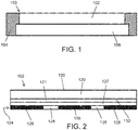
- FIG. 1 is a schematic cross-sectional view of a decorative or architectural panel, which will be referred to as an image unit 100.
- the image unit 100 includes an image panel 102 seated within a housing 104. Also disposed within the housing 104 is a backlight unit 106. The backlight unit 106 is positioned behind the image panel 102.
- the image unit 100 may be incorporated into another structure (e.g., an architectural structure, such as a wall, floor, ceiling, door, etc.) or device (e.g., an electronic device, such as a cellphone, laptop, monitor, tablet, etc.).
- the backlight unit 106 is at least one of an incandescent lamp, an LED array, an electroluminescent panel, cold cathode fluorescent lamps, hot cathode fluorescent lamps, external electrode fluorescent lamps, or an active display unit (as discussed below). In embodiments, the backlight unit 106 is configured to provide 300 lumens to 350 lumens of illumination on the image panel 102.
- FIG. 2 depicts the structure of the image panel 102.
- the image panel 102 includes a transparent substrate 120, a first image layer 121, a diffuser layer 122, and a second image layer 124.
- the second image layer 124 includes at least one opaque region 126 and at least one image region 128.
- the substrate 120 is a transparent glass or plastic.
- suitable glass substrates 120 may include at least one of silicates, soda lime silicates, borosilicates, aluminosilicates, aluminoborosilicates, alkali aluminosilicates, and alkaline earth aluminosilicates, among others.
- Such glasses may be chemically or thermally strengthened.
- a commercially available glass suitable for use is the transparent substrate is Gorilla® glass (available from Corning Incorporated, Corning, NY).
- Suitable transparent plastic substrates 120 include polycarbonate or acrylic panels.
- the substrate 120 has a first major surface 130 and a second major surface 132.
- the first major surface 130 is on the opposite side of the substrate 120 from the second major surface 132.
- the first major surface 130 is a viewing surface in that the first major surface is directed at a viewer.
- the second major surface 132 faces the backlight unit 106 (as shown in FIG. 1 ).
- the first image layer 121 is illuminated by ambient lighting such that the first image layer is seen by the viewer when the backlight unit 106 is inactive.
- the second major surface 132 is illuminated causing the viewer to see a composite image of the first image layer 121 and the image regions of the second image layer 124.
- the transparent substrate 120 has a thickness as defined by a distance between a first major surface 130 and a second major surface 132 of no more than 2 mm, no more than 0.7 mm, or no more than 0.55 mm. In embodiments, the transparent substrate 120 has a thickness of at least 0.1 mm, at least 0.2 mm, at least 0.3 mm, or at least 0.4 mm.
- the first image layer 121 is disposed on the first major surface 130 or the second major surface 132 of the substrate 120. In embodiments, the first image layer 121 is disposed on the second major surface 132 so that the substrate 120 is between the viewer and the first image layer 121 so as to protect the first image layer 121 from damage.
- the first image layer 121 can be applied on the substrate 120 in a variety of ways. In an embodiment, the first image layer 121 is printed on the substrate 120 using a technique such as inkjet printing, slot printing, screen printing, pad printing, or gravure printing, among others. In another embodiment, the first image layer 121 is a decal or transfer that is adhered to the substrate 120. In embodiments, the first image layer 121 is semitransparent, having an optical density of 0.5 or less.
- the diffuser layer 122 is disposed over the first image layer 121 and is designed to scatter and reflect light. In this way, the diffuser layer 122 enhances visibility of the first image layer 121 by reflecting ambient light passing through the semitransparent first image layer 121. Additionally, the diffuser layer 122 scatters light, including light that passes through the first image layer 121 and diffuser layer 122 to effectively hide the image regions 128 of the second image layer 124 when the backlight unit 106 is not active.
- the diffuser layer 122 has an optical density of 1.0 to 2.0.
- the diffuser layer 122 is a layer of white material. In particular embodiments, the diffuser layer 122 is a white ink layer.
- the diffuser layer 122 can be made up of multiple layers or applications of white material, such as a white ink, until the desired total optical density of the diffuser layer 122 is reached.
- the total optical density of the substrate 120, first image layer 121, and diffuser layer 122 is from 1.5 to 2.5.
- the second image layer 124 is disposed over the diffuser layer 122.
- the second image layer 124 includes one or more opaque regions 126 and one or more image regions 128.
- the opaque regions 126 are designed to block light from the backlight unit 106 from shining through the first image layer 121.
- the opaque regions 126 are made from a material configured to increase the overall optical density of the image panel to at least 3.0 in the opaque regions 126.
- the opaque regions 126 are a black ink layer.
- the image regions 128 are semitransparent like the first image layer 121 and have an optical density of 0.5 or less. In this way, light is configured to travel from the backlight unit 106 through the image panel 106 in the image regions 128.
- the optical density of the image panel 102 in the image regions 128 is less than 3.0.
- the second image layer 124 can be applied on the diffuser layer 122 using the above described printing or image transfer techniques. Further, in embodiments, the second image layer 124 can be applied to the image panel 106 in one or two steps. In an embodiment, the opaque regions 126 are applied in a first step to create essentially a negative of the second image. Thereafter, the image regions 124 are applied in a second step. Alternatively, the image regions 128 could be applied first, followed by the opaque regions 126. In another embodiment, the opaque regions 126 and the image regions 128 can be applied at the same time, e.g., by inkjet printing a continuous second image layer 124.
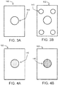
- FIGS. 3A and 3B depict an example of the image panel 102 converting from the first image 140 ( FIG. 3A ) of the first image layer 121 to the composite image 142 ( FIG. 3B ) of the first image layer 121 and image regions 128.
- the composite image 142 is one in which elements are added to the first image 140.
- the first image 140 consists of a shape in the center of the image panel 102.
- the image regions 128 add elements to the corners of the image panel 102 to create the composite image 142.
- FIGS. 4A and 4B depict another example of the image panel 102 converting from a first image 140 ( FIG. 4A ) to a composite image 142 ( FIG. 4B ).
- This example demonstrates a color change of the first image 140.
- the first image layer 140 is a first color (e.g., green) and the composite image 142 is a second color (e.g., orange).
- a simulation can be performed using color wheels printed on separate substrates.
- a first substrate can include a first image layer 121 of a first color wheel with a diffuser layer 122 disposed thereover.
- a second color wheel is printed as the second image layer 124.
- a desired first color is selected and, having a desired second color in mind, the second color wheel on the second substrate is illuminated with a backlight and is rotated until the desired second color is illuminated at the location of the desired first color.
- the color of the image regions 128 of the second image layer 124 can be determined in order to produce the desired second color of the composite image 142 when mixed with the first color of the first image 140.
- the selection of the colors can further be facilitated using the CMYK color model, which is a subtractive color model, along with halftoning.
- the backlight unit 106 may emit white light, and the first image 140 may subtract a combination of cyan, magenta, or yellow from the light to produce the first color.
- the second color may thus be selected to subtract additional amounts of cyan, magenta, or yellow from the light to produce the second color.
- the densities of the image layers 121, 124 can be determined to produce the exact color desired when the image panel 102 is illuminated.
- the first color is printed in varying densities horizontally or vertically across a first substrate, e.g., going from low density (10%) to high density (100%) in predetermined increments, and the diffuser layer is printed over the first color.
- the second color is then printed in the opposite direction (e.g., vertically if the first color is printed horizontally) across the second substrate.
- the substrates are then overlaid and placed over a backlight unit that illuminates the substrates, providing color mixing for the first and second colors at varying color densities.
- the layers 121, 122, 124 can be printed or applied on the substrate 120 of the image panel 102.
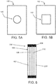
- FIGS. 5A and 5B depict an embodiment of creation of a new image as the composite image 142 ( FIG. 5B ) from the first image 140 ( FIG. 5A ).
- the first image 140 is of a circle
- the composite image 142 is of a square when the image panel 102 is illuminated by a backlight unit 106.
- the composite image 142 may include combinations of two or more of the example transitions.
- the first image shown in FIG. 3A may include a first color for the shape in the center of the image panel and a second color for the area surrounding the shape.
- the composite image 142 would exhibit both additional elements and a color change (e.g., as shown schematically in FIGS. 4A and 4B ).
- the center shape of FIG. 3A could also transform into a new image as demonstrated in FIG. 5B depending on the particular configuration of the second image layer 124.
- FIG. 6 depicts an embodiment of the image unit 100 incorporated into an electronic device 200 as a back panel of the electronic device.
- the electronic device 200 includes a display unit 210 disposed behind a cover glass 220.
- the display unit 210 and cover glass 220 may have various intervening layers, such as touch-sensitive layers that provide touch functionality for interacting with the display unit 210.
- the electronic device 200 is, e.g., a cellphone, a tablet, a laptop, or a monitor, among other possibilities.
- the display unit 210 may be any one of a light emitting diode (LED) display device, an organic LED (OLED) display device, quantum dot (QLED) display device, plasma display device, or liquid crystal display (LCD) device, among others.
- LED light emitting diode
- OLED organic LED
- QLED quantum dot
- plasma display device plasma display device
- LCD liquid crystal display
- the display unit 210 may incorporate a backlight unit 106 in which case the image panel 102 and display unit 210 may be backlit by the same backlight unit 106. In other embodiments, a separate backlight unit 106 is incorporated and faced rearward to provide backlighting for the image panel 102.
- electronic device 200 has a sleep mode or an off mode in which the display unit 210 and backlight 106 are not active. In this mode, the first image 140 of the image panel 102 will be seen by a user.
- the backlight unit 106 activates the display unit 210 and illuminates the image panel 102 to provide decorative or informational effect as the composite image 142 of the image panel 102.
Landscapes
- Physics & Mathematics (AREA)
- Engineering & Computer Science (AREA)
- General Physics & Mathematics (AREA)
- Theoretical Computer Science (AREA)
- Computer Hardware Design (AREA)
- Nonlinear Science (AREA)
- Chemical & Material Sciences (AREA)
- Crystallography & Structural Chemistry (AREA)
- Optics & Photonics (AREA)
- Mathematical Physics (AREA)
- Illuminated Signs And Luminous Advertising (AREA)
- Devices For Indicating Variable Information By Combining Individual Elements (AREA)
- Planar Illumination Modules (AREA)
Abstract
Description
- This application claims the benefit of priority under 35 U.S.C. §120 of
U.S. Provisional Application Serial No. 63/004,723 filed on April 03, 2020 - The disclosure relates to a decorative image panel, and more particularly to a decorative image panel displaying a first image in ambient light and a composite image when the image panel is backlit.
- Glass has been incorporated in decorative, architectural, and electronic designs. In many instances, glass is used specifically for its transparency. However, in other instances, images can be incorporated on or in the glass to provide decorative glass. As glass continues to be engineered for more and varied uses, designers and consumers have looked for different ways to provide decorative effects on the glass surface.
- In one aspect, embodiments of the disclosure relate to an image panel. The image panel includes a transparent substrate having a first major surface and a second major surface. The second major surface is opposite the first major surface. The image panel also includes first image layer disposed on the second major surface of the transparent substrate. A diffuser layer is disposed on the first image layer, and a second image layer is disposed on the diffuser layer. The second image layer includes at least one mask region and at least one image region An optical density of the image panel is at least 3.0 in the at least one mask region and less than 3.0 in the at least one image region. The at least one image region is not visible from the first major surface of the transparent substrate when light is not incident upon the second major surface of the transparent substrate. The at least one image region is visible from the first major surface of the transparent substrate and forms a composite image with the first image layer when light is incident upon the second major surface of the transparent substrate.
- In another aspect, embodiments of the disclosure relate to a method of preparing an image panel. In the method, a first image layer is applied on a transparent substrate. The transparent substrate includes a first major surface and a second major surface opposite to the first major surface. The first image layer is disposed on the second major surface. A diffuser layer is applied on the first image layer, and a second image layer is applied on the diffuser layer. The second image layer includes at least one mask region and at least one image region. An optical density of the image panel is at least 3.0 in the at least one mask region and less than 3.0 in the at least one image region. Only the first image layer is visible from the first major surface when no light is incident upon the second major surface, and a composite image of the first image layer and the at least one image region of the second image layer is visible from the first major surface when light is incident on the second major surface.
- In still another aspect, embodiments of the disclosure relate to a method of producing an image on an image panel. The image panel includes a transparent substrate, a first image layer disposed on the transparent substrate, a diffuser layer disposed on the first image layer, and a second image layer disposed on the diffuser layer. The second image layer has at least one mask region in which the optical density of the image panel is at least 3.0 and at least one image region in which the optical density of the image panel is less than 3.0. In the method, the second image layer of the image panel is illuminated with a backlight from a rear side of the image panel so that a composite image of the first image layer and the at least one image region is seen from a viewing side of the image panel opposite to the rear side.
- In a further aspect, embodiments of the disclosure relate to an image unit. The image unit includes an image panel having a viewing side and a rear side opposite to the viewing side and a backlight on the rear side of the image panel. The image panel includes a transparent substrate having a first major surface on the viewing side and a second major surface on the rear side. A first image layer is disposed on the second major surface of the transparent substrate, and a diffuser layer is disposed on the first image layer. A second image layer having at least one mask region and at least one image region is disposed on the diffuser layer. An optical density of the image panel is at least 3.0 in the at least one mask region and less than 3.0 in the at least one image region. Only a first image defined by the first image layer can be seen from the viewing side when no light is incident upon the rear side of the image panel. The backlight is configured to illuminate the second major surface of transparent substrate such that a composite image of the first image layer and the at least one image region is seen from the viewing side.
- Additional features and advantages will be set forth in the detailed description which follows, and in part will be readily apparent to those skilled in the art from that description or recognized by practicing the embodiments as described herein, including the detailed description which follows, the claims, as well as the appended drawings.
- It is to be understood that both the foregoing general description and the following detailed description are merely exemplary, and are intended to provide an overview or framework to understanding the nature and character of the claims.
- The accompanying drawings are included to provide a further understanding, and are incorporated in and constitute a part of this specification. The drawings illustrate one or more embodiment(s), and together with the description serve to explain principles and operation of the various embodiments. In the drawings:
-
FIG. 1 depicts a schematic, partial cross-sectional view of a backlit image unit having an image panel configured to display a composite image, according to an exemplary embodiment; -
FIG. 2 depicts a schematic cross-sectional view of an image panel, according to an exemplary embodiment; -
FIGS. 3A and 3B depict a transition of an image panel from a first image to a composite image having additional elements, according to an exemplary embodiment; -
FIGS. 4A and 4B depict a transition of an image panel from a first image of a first color to a composite image of a second color, according to an exemplary embodiment; -
FIGS. 5A and 5B depict a transition of an image panel from a first image to a new composite image, according to an exemplary embodiment; and -
FIG. 6 is a schematic depiction of an electronic device having an image unit as a back panel, according to an exemplary embodiment. - Referring generally to the figures, various embodiments of an image panel configured to display a composite image when illuminated by a backlight unit are provided. In embodiments, the image panel may be a decorative or architectural panel that displays a first image in ambient light and an image that is a composite of the first image and an underlying image when the panel is backlit. In embodiments, the image panel includes a first image layer disposed on a transparent substrate. Disposed on the first image layer is a diffuser layer configured to block the underlying image layer in ambient light. The underlying image is disposed on the diffuser layer and includes opaque regions and an image regions. When a backlight unit illuminates the underlying image layer, the first image is altered by changing color, adding effects to the image, and/or creating a new image. These effects are collectively referred to as a "composite image" because the image viewable to the user is a composite of the two image layers.
- In a particular embodiment, the image panel is incorporated into an electronic device as, e.g., a back or side panel of the electronic device, and uses the backlight of the display unit to also illuminate the image panel. Thus, taking as an example a cellphone, the back panel of the phone may display a first image when the cellphone is in sleep mode, but upon activating the front display, the back panel will then display a composite image using the activated backlight unit. The concept applies to other electronic devices, especially other electronic devices that include displays and already incorporate a backlight, such as laptops, tablets, monitors, etc. These and other aspects and advantages will be described below and in relation to the figures. Embodiments of the image panel discussed herein are provided by way of example and not by way of limitation.
-
FIG. 1 is a schematic cross-sectional view of a decorative or architectural panel, which will be referred to as animage unit 100. Theimage unit 100 includes animage panel 102 seated within ahousing 104. Also disposed within thehousing 104 is abacklight unit 106. Thebacklight unit 106 is positioned behind theimage panel 102. As will be discussed below, theimage unit 100 may be incorporated into another structure (e.g., an architectural structure, such as a wall, floor, ceiling, door, etc.) or device (e.g., an electronic device, such as a cellphone, laptop, monitor, tablet, etc.). In embodiments, thebacklight unit 106 is at least one of an incandescent lamp, an LED array, an electroluminescent panel, cold cathode fluorescent lamps, hot cathode fluorescent lamps, external electrode fluorescent lamps, or an active display unit (as discussed below). In embodiments, thebacklight unit 106 is configured to provide 300 lumens to 350 lumens of illumination on theimage panel 102. -
FIG. 2 depicts the structure of theimage panel 102. As can be seen inFIG. 2 , theimage panel 102 includes atransparent substrate 120, afirst image layer 121, adiffuser layer 122, and asecond image layer 124. Thesecond image layer 124 includes at least oneopaque region 126 and at least oneimage region 128. - In embodiments, the
substrate 120 is a transparent glass or plastic. For example,suitable glass substrates 120 may include at least one of silicates, soda lime silicates, borosilicates, aluminosilicates, aluminoborosilicates, alkali aluminosilicates, and alkaline earth aluminosilicates, among others. Such glasses may be chemically or thermally strengthened. A commercially available glass suitable for use is the transparent substrate is Gorilla® glass (available from Corning Incorporated, Corning, NY). Suitable transparentplastic substrates 120 include polycarbonate or acrylic panels. - The
substrate 120 has a firstmajor surface 130 and a secondmajor surface 132. The firstmajor surface 130 is on the opposite side of thesubstrate 120 from the secondmajor surface 132. In embodiments, the firstmajor surface 130 is a viewing surface in that the first major surface is directed at a viewer. The secondmajor surface 132 faces the backlight unit 106 (as shown inFIG. 1 ). As will be discussed more fully below, thefirst image layer 121 is illuminated by ambient lighting such that the first image layer is seen by the viewer when thebacklight unit 106 is inactive. When thebacklight unit 106 is active, the secondmajor surface 132 is illuminated causing the viewer to see a composite image of thefirst image layer 121 and the image regions of thesecond image layer 124. Thetransparent substrate 120 has a thickness as defined by a distance between a firstmajor surface 130 and a secondmajor surface 132 of no more than 2 mm, no more than 0.7 mm, or no more than 0.55 mm. In embodiments, thetransparent substrate 120 has a thickness of at least 0.1 mm, at least 0.2 mm, at least 0.3 mm, or at least 0.4 mm. - The
first image layer 121 is disposed on the firstmajor surface 130 or the secondmajor surface 132 of thesubstrate 120. In embodiments, thefirst image layer 121 is disposed on the secondmajor surface 132 so that thesubstrate 120 is between the viewer and thefirst image layer 121 so as to protect thefirst image layer 121 from damage. Thefirst image layer 121 can be applied on thesubstrate 120 in a variety of ways. In an embodiment, thefirst image layer 121 is printed on thesubstrate 120 using a technique such as inkjet printing, slot printing, screen printing, pad printing, or gravure printing, among others. In another embodiment, thefirst image layer 121 is a decal or transfer that is adhered to thesubstrate 120. In embodiments, thefirst image layer 121 is semitransparent, having an optical density of 0.5 or less. - The
diffuser layer 122 is disposed over thefirst image layer 121 and is designed to scatter and reflect light. In this way, thediffuser layer 122 enhances visibility of thefirst image layer 121 by reflecting ambient light passing through the semitransparentfirst image layer 121. Additionally, thediffuser layer 122 scatters light, including light that passes through thefirst image layer 121 anddiffuser layer 122 to effectively hide theimage regions 128 of thesecond image layer 124 when thebacklight unit 106 is not active. In embodiments, thediffuser layer 122 has an optical density of 1.0 to 2.0. In embodiments, thediffuser layer 122 is a layer of white material. In particular embodiments, thediffuser layer 122 is a white ink layer. Further, in embodiments, thediffuser layer 122 can be made up of multiple layers or applications of white material, such as a white ink, until the desired total optical density of thediffuser layer 122 is reached. In embodiments, the total optical density of thesubstrate 120,first image layer 121, anddiffuser layer 122 is from 1.5 to 2.5. - The
second image layer 124 is disposed over thediffuser layer 122. As discussed above, thesecond image layer 124 includes one or moreopaque regions 126 and one ormore image regions 128. Theopaque regions 126 are designed to block light from thebacklight unit 106 from shining through thefirst image layer 121. Thus, theopaque regions 126 are made from a material configured to increase the overall optical density of the image panel to at least 3.0 in theopaque regions 126. In an embodiment, theopaque regions 126 are a black ink layer. Theimage regions 128 are semitransparent like thefirst image layer 121 and have an optical density of 0.5 or less. In this way, light is configured to travel from thebacklight unit 106 through theimage panel 106 in theimage regions 128. Thus, the optical density of theimage panel 102 in theimage regions 128 is less than 3.0. - As with the
first image layer 121, thesecond image layer 124 can be applied on thediffuser layer 122 using the above described printing or image transfer techniques. Further, in embodiments, thesecond image layer 124 can be applied to theimage panel 106 in one or two steps. In an embodiment, theopaque regions 126 are applied in a first step to create essentially a negative of the second image. Thereafter, theimage regions 124 are applied in a second step. Alternatively, theimage regions 128 could be applied first, followed by theopaque regions 126. In another embodiment, theopaque regions 126 and theimage regions 128 can be applied at the same time, e.g., by inkjet printing a continuoussecond image layer 124. -
FIGS. 3A and 3B depict an example of theimage panel 102 converting from the first image 140 (FIG. 3A ) of thefirst image layer 121 to the composite image 142 (FIG. 3B ) of thefirst image layer 121 andimage regions 128. In this embodiment, thecomposite image 142 is one in which elements are added to thefirst image 140. As shown schematically, thefirst image 140 consists of a shape in the center of theimage panel 102. When the image panel is illuminated by abacklight unit 106, theimage regions 128 add elements to the corners of theimage panel 102 to create thecomposite image 142. -
FIGS. 4A and 4B depict another example of theimage panel 102 converting from a first image 140 (FIG. 4A ) to a composite image 142 (FIG. 4B ). This example demonstrates a color change of thefirst image 140. For example, thefirst image layer 140 is a first color (e.g., green) and thecomposite image 142 is a second color (e.g., orange). In order to arrive at the desiredsecond color 142, a simulation can be performed using color wheels printed on separate substrates. For example, a first substrate can include afirst image layer 121 of a first color wheel with adiffuser layer 122 disposed thereover. On the second substrate, a second color wheel is printed as thesecond image layer 124. Thereafter, a desired first color is selected and, having a desired second color in mind, the second color wheel on the second substrate is illuminated with a backlight and is rotated until the desired second color is illuminated at the location of the desired first color. In this way, the color of theimage regions 128 of thesecond image layer 124 can be determined in order to produce the desired second color of thecomposite image 142 when mixed with the first color of thefirst image 140. - In embodiments, the selection of the colors can further be facilitated using the CMYK color model, which is a subtractive color model, along with halftoning. In particular, the
backlight unit 106 may emit white light, and thefirst image 140 may subtract a combination of cyan, magenta, or yellow from the light to produce the first color. The second color may thus be selected to subtract additional amounts of cyan, magenta, or yellow from the light to produce the second color. - Once the two colors for the
first image layer 121 and theimage regions 128 of thesecond image layer 124 are selected, the densities of the image layers 121, 124 can be determined to produce the exact color desired when theimage panel 102 is illuminated. In an embodiment, the first color is printed in varying densities horizontally or vertically across a first substrate, e.g., going from low density (10%) to high density (100%) in predetermined increments, and the diffuser layer is printed over the first color. The second color is then printed in the opposite direction (e.g., vertically if the first color is printed horizontally) across the second substrate. The substrates are then overlaid and placed over a backlight unit that illuminates the substrates, providing color mixing for the first and second colors at varying color densities. - Upon determining the colors for the
first image layer 121 and theimage regions 128 of thesecond image layer 124, thelayers substrate 120 of theimage panel 102. -
FIGS. 5A and 5B depict an embodiment of creation of a new image as the composite image 142 (FIG. 5B ) from the first image 140 (FIG. 5A ). As shown inFIG. 5A , thefirst image 140 is of a circle, and as shown inFIG. 5B , thecomposite image 142 is of a square when theimage panel 102 is illuminated by abacklight unit 106. - The examples depicted in
FIGS. 3A-3B, 4A-4B , and5A-5B are simplistic in nature and are meant to illustrate different possibilities for producingcomposite images 142. In practice, thecomposite image 142 may include combinations of two or more of the example transitions. For example, the first image shown inFIG. 3A may include a first color for the shape in the center of the image panel and a second color for the area surrounding the shape. Thus, when theimage regions 128 are illuminated, the shapes in the corners will not only be shown but also be a combination of the underlying color of theimage regions 128 and the surrounding color of thefirst image layer 121. In such an embodiment, thecomposite image 142 would exhibit both additional elements and a color change (e.g., as shown schematically inFIGS. 4A and 4B ). Similarly, the center shape ofFIG. 3A could also transform into a new image as demonstrated inFIG. 5B depending on the particular configuration of thesecond image layer 124. -
FIG. 6 depicts an embodiment of theimage unit 100 incorporated into anelectronic device 200 as a back panel of the electronic device. InFIG. 6 , theelectronic device 200 includes adisplay unit 210 disposed behind acover glass 220. Thedisplay unit 210 andcover glass 220 may have various intervening layers, such as touch-sensitive layers that provide touch functionality for interacting with thedisplay unit 210. In embodiments, theelectronic device 200 is, e.g., a cellphone, a tablet, a laptop, or a monitor, among other possibilities. Thedisplay unit 210 may be any one of a light emitting diode (LED) display device, an organic LED (OLED) display device, quantum dot (QLED) display device, plasma display device, or liquid crystal display (LCD) device, among others. Thedisplay unit 210 may incorporate abacklight unit 106 in which case theimage panel 102 anddisplay unit 210 may be backlit by thesame backlight unit 106. In other embodiments, aseparate backlight unit 106 is incorporated and faced rearward to provide backlighting for theimage panel 102. - In embodiments,
electronic device 200 has a sleep mode or an off mode in which thedisplay unit 210 andbacklight 106 are not active. In this mode, thefirst image 140 of theimage panel 102 will be seen by a user. When a user activates theelectronic device 200, thebacklight unit 106 activates thedisplay unit 210 and illuminates theimage panel 102 to provide decorative or informational effect as thecomposite image 142 of theimage panel 102. - Unless otherwise expressly stated, it is in no way intended that any method set forth herein be construed as requiring that its steps be performed in a specific order. Accordingly, where a method claim does not actually recite an order to be followed by its steps or it is not otherwise specifically stated in the claims or descriptions that the steps are to be limited to a specific order, it is in no way intended that any particular order be inferred. In addition, as used herein, the article "a" is intended to include one or more than one component or element, and is not intended to be construed as meaning only one.
- It will be apparent to those skilled in the art that various modifications and variations can be made without departing from the spirit or scope of the disclosed embodiments. Since modifications, combinations, sub-combinations and variations of the disclosed embodiments incorporating the spirit and substance of the embodiments may occur to persons skilled in the art, the disclosed embodiments should be construed to include everything within the scope of the appended claims and their equivalents.
Claims (15)
- An image panel, comprising:a transparent substrate comprising a first major surface and a second major surface, the second major surface being opposite the first major surface;a first image layer disposed on the second major surface of the transparent substrate;a diffuser layer disposed on the first image layer;a second image layer disposed on the diffuser layer, the second image layer comprising at least one mask region and at least one image region;wherein an optical density of the image panel is at least 3.0 in the at least one mask region and less than 3.0 in the at least one image region; andwherein the at least one image region is not visible from the first major surface of the transparent substrate when light is not incident upon the second major surface of the transparent substrate; andwherein the at least one image region is visible from the first major surface of the transparent substrate and forms a composite image with the first image layer when light is incident upon the second major surface of the transparent substrate.
- The image panel of claim 1, wherein the transparent substrate is at least one of a glass or a plastic.
- The image panel of claim 1 or claim 2, wherein the first image layer comprises an optical density of 0.5 or less.
- The image panel of any of the preceding claims, wherein the optical density of the diffuser layer is from 1.0 to 2.0.
- The image panel of any of the preceding claims, wherein the optical density of the at least one image region of the second image layer is 0.5 or less.
- The image panel of any of the preceding claims, wherein, in the at least one image region, the first image layer comprises a first color having first CMYK values, the second image layer comprises a second color having second CMYK values, and the composite image comprises a third color having third CMYK values that are different from the first CMYK values and the second CMYK values.
- The image panel of any of the preceding claims, wherein the first image layer comprises a decal adhered to the second major surface of the transparent substrate.
- The image panel of any of claims 1-6, wherein the first image layer comprises an ink layer printed onto the second major surface of the transparent substrate.
- The image panel of any of the preceding claims, wherein the diffuser layer comprises one or more white ink layers printed onto the first image layer.
- The image panel of any of the preceding claims, wherein the at least one mask region comprises black ink printed onto the diffuser layer.
- The image panel of any of the preceding claims, wherein the at least one image region comprises an ink region disposed on the diffuser layer.
- A method of preparing an image panel, comprising:applying a first image layer on a transparent substrate, the transparent substrate comprising a first major surface and a second major surface opposite to the first major surface, the first image layer being disposed on the second major surface;applying a diffuser layer on the first image layer; andapplying a second image layer comprising at least one mask region and at least one image region on the diffuser layer, wherein an optical density of the image panel is at least 3.0 in each of the at least one mask region and less than 3.0 in each of the at least one image region; andwherein only the first image layer is visible from the first major surface when no light is incident upon the second major surface and a composite image of the first image layer and the at least one image region of the second image layer is visible from the first major surface when light is incident on the second major surface.
- The method of claim 12, wherein the transparent substrate is at least one of a glass or a plastic.
- The method of claim 12 or claim 13, wherein the first image layer comprises an optical density of 0.5 or less, wherein the optical density of the diffuser layer is from 1.0 to 2.0, and wherein the optical density of the at least one image region of the second image layer is 0.5 or less.
- The method of any of claims 12-14, wherein applying the first image layer comprises adhering a decal to the second major surface of the transparent substrate, or printing an ink layer onto the second major surface of the transparent substrate,
wherein applying the diffuser layer comprises printing one or more white ink layers onto the first image layer, and
wherein applying the second image layer comprises applying the at least one mask region simultaneously with the at least one image region.
Applications Claiming Priority (1)
| Application Number | Priority Date | Filing Date | Title |
|---|---|---|---|
| US202063004723P | 2020-04-03 | 2020-04-03 |
Publications (1)
| Publication Number | Publication Date |
|---|---|
| EP3888932A1 true EP3888932A1 (en) | 2021-10-06 |
Family
ID=75362457
Family Applications (1)
| Application Number | Title | Priority Date | Filing Date |
|---|---|---|---|
| EP21166634.2A Pending EP3888932A1 (en) | 2020-04-03 | 2021-04-01 | Image panel having composite image using color changing with backlight illumination |
Country Status (3)
| Country | Link |
|---|---|
| US (2) | US11681173B2 (en) |
| EP (1) | EP3888932A1 (en) |
| CN (1) | CN113496649B (en) |
Families Citing this family (1)
| Publication number | Priority date | Publication date | Assignee | Title |
|---|---|---|---|---|
| WO2024072788A1 (en) * | 2022-09-30 | 2024-04-04 | Corning Incorporated | Deadfront articles with multi-layer optical structures and associated methods |
Citations (3)
| Publication number | Priority date | Publication date | Assignee | Title |
|---|---|---|---|---|
| BE420700Q (en) * | 1934-12-19 | 1937-04-30 | Transart Aktiebolag | Device and method for representing objects of all kinds |
| US9945539B1 (en) * | 2016-10-19 | 2018-04-17 | Lu Su | Backlit display assembly |
| WO2020014064A1 (en) * | 2018-07-12 | 2020-01-16 | Corning Incorporated | Deadfront configured for color matching |
Family Cites Families (29)
| Publication number | Priority date | Publication date | Assignee | Title |
|---|---|---|---|---|
| DE4426344C2 (en) | 1993-09-07 | 1998-02-26 | Ford Motor Co | Display instrument |
| JP4050802B2 (en) * | 1996-08-02 | 2008-02-20 | シチズン電子株式会社 | Color display device |
| JP2003255329A (en) * | 2002-02-28 | 2003-09-10 | Hitachi Chem Co Ltd | Manufacturing method of diffused reflecting plate for reflective liquid crystal display and photosensitive element for forming diffused reflective ground layer for manufacturing the same |
| GB2416063A (en) * | 2004-07-08 | 2006-01-11 | Kristjan Arnthorsson | Layered graphic display panel |
| JP2006279228A (en) * | 2005-03-28 | 2006-10-12 | Fuji Xerox Co Ltd | Image pickup apparatus |
| US8408773B2 (en) * | 2007-03-19 | 2013-04-02 | Innotec Corporation | Light for vehicles |
| GB2450090A (en) * | 2007-06-11 | 2008-12-17 | Frederick Douglas Williams | Fascia apparatus for use in a housing with a self-luminous light source |
| CN101859515B (en) * | 2009-04-10 | 2013-07-31 | 鸿富锦精密工业(深圳)有限公司 | Display module and light-emitting marker having same |
| US9595960B2 (en) | 2010-05-04 | 2017-03-14 | Whirlpool Corporation | Dead-front user interface |
| KR101876659B1 (en) * | 2014-02-21 | 2018-07-09 | 코니카 미놀타 가부시키가이샤 | Display device |
| US10699612B2 (en) * | 2014-10-27 | 2020-06-30 | Sharp Kabushiki Kaisha | Display system with specular reflective mode |
| DE202015008937U1 (en) | 2015-02-26 | 2016-03-16 | Schott Ag | Coated glass or glass ceramic article |
| KR20180016431A (en) | 2015-06-02 | 2018-02-14 | 코닝 인코포레이티드 | Multifunctional material system for surface display units |
| KR102438886B1 (en) | 2015-10-22 | 2022-09-01 | 삼성디스플레이 주식회사 | Array substrate and display device including same |
| JP6708462B2 (en) * | 2016-03-31 | 2020-06-10 | キヤノン株式会社 | Image processing apparatus and image processing method |
| US9861883B1 (en) * | 2016-06-17 | 2018-01-09 | Mohawk Fine Papers Inc. | Secure substrate for scratch-off products |
| TWI800484B (en) | 2016-06-28 | 2023-05-01 | 美商康寧公司 | Laminating thin strengthened glass to curved molded plastic surface for decorative and display cover application |
| WO2018009504A1 (en) | 2016-07-05 | 2018-01-11 | Corning Incorporated | Cold-formed glass article and assembly process thereof |
| US10712850B2 (en) | 2017-01-03 | 2020-07-14 | Corning Incorporated | Vehicle interior systems having a curved cover glass and a display or touch panel and methods for forming the same |
| EP3681847B1 (en) | 2017-09-12 | 2025-01-29 | Corning Incorporated | Tactile elements for deadfronted glass and methods of making the same |
| TWI873668B (en) | 2017-09-13 | 2025-02-21 | 美商康寧公司 | Light guide-based deadfront for display, related methods and vehicle interior systems |
| JP2019153436A (en) * | 2018-03-01 | 2019-09-12 | シャープ株式会社 | Luminaire and display device |
| TWI641779B (en) * | 2018-05-24 | 2018-11-21 | 和碩聯合科技股份有限公司 | Light-emitting case |
| WO2020098665A1 (en) * | 2018-11-14 | 2020-05-22 | 上海延锋金桥汽车饰件系统有限公司 | Vehicle interior trim piece |
| US10696218B1 (en) * | 2018-12-20 | 2020-06-30 | Panasonic Intellectual Property Management Co., Ltd. | Illumination device |
| US10962701B2 (en) * | 2019-04-04 | 2021-03-30 | S.V.V. Technology Innovations, Inc. | Wide-area solid-state illumination devices and systems |
| US10930259B2 (en) | 2019-04-25 | 2021-02-23 | Aaron Cunningham | Soundproof case for voice devices |
| US11745671B2 (en) * | 2020-03-27 | 2023-09-05 | Faurecia Interior Systems, Inc. | Backlit vehicle interior panel with specialty materials |
| US11772361B2 (en) | 2020-04-02 | 2023-10-03 | Corning Incorporated | Curved glass constructions and methods for forming same |
-
2021
- 2021-03-31 US US17/218,479 patent/US11681173B2/en active Active
- 2021-04-01 EP EP21166634.2A patent/EP3888932A1/en active Pending
- 2021-04-02 CN CN202110363823.0A patent/CN113496649B/en active Active
-
2023
- 2023-05-09 US US18/195,127 patent/US12228810B2/en active Active
Patent Citations (3)
| Publication number | Priority date | Publication date | Assignee | Title |
|---|---|---|---|---|
| BE420700Q (en) * | 1934-12-19 | 1937-04-30 | Transart Aktiebolag | Device and method for representing objects of all kinds |
| US9945539B1 (en) * | 2016-10-19 | 2018-04-17 | Lu Su | Backlit display assembly |
| WO2020014064A1 (en) * | 2018-07-12 | 2020-01-16 | Corning Incorporated | Deadfront configured for color matching |
Also Published As
| Publication number | Publication date |
|---|---|
| CN113496649B (en) | 2026-04-24 |
| US20210311348A1 (en) | 2021-10-07 |
| CN113496649A (en) | 2021-10-12 |
| US20230273470A1 (en) | 2023-08-31 |
| US12228810B2 (en) | 2025-02-18 |
| US11681173B2 (en) | 2023-06-20 |
Similar Documents
| Publication | Publication Date | Title |
|---|---|---|
| CN102466179B (en) | The display device of back light unit and use back light unit | |
| US8264135B2 (en) | Bezel-less electronic display | |
| CN106033156B (en) | Display device and display method | |
| US20040041504A1 (en) | Bezel-less electronic display | |
| JP7286943B2 (en) | Decorative film and display device | |
| WO2012036081A1 (en) | Display device | |
| US20170363797A1 (en) | Transparent display with improved contrast and transmission | |
| US12228810B2 (en) | Image panel having composite image using color changing with backlight illumination | |
| JP7671439B2 (en) | Decorative sheet, display device with decorative sheet, and article with decorative sheet | |
| WO2026012415A1 (en) | Display assembly, manufacturing method therefor, and vehicle interior component comprising same | |
| CN106597749A (en) | Backlight module and electronic equipment | |
| US20110193790A1 (en) | Touch panel module with illumination function | |
| US20250199351A1 (en) | Double-sided display device and driving method thereof | |
| JP7180278B2 (en) | Decorative film and display device | |
| US20140211455A1 (en) | Image display device with organic light-emitting diode | |
| WO2025035941A1 (en) | Display module | |
| TWM643856U (en) | Display device | |
| US20260063939A1 (en) | Display device | |
| JPH11264973A (en) | Planar light emitting device and liquid crystal display device using the same | |
| CN219497288U (en) | Glass display with back surface displaying image and text | |
| JP2026056230A (en) | display device | |
| CN121316722A (en) | A light-emitting interior trim system with transparent display function | |
| CN212540955U (en) | Panel assembly for realizing integrated black display by matching with TFT display screen | |
| CN121364575A (en) | Manufacturing method of luminous interior trim part with transparent display function | |
| CN212749467U (en) | Diffusion film of backlight module |
Legal Events
| Date | Code | Title | Description |
|---|---|---|---|
| PUAI | Public reference made under article 153(3) epc to a published international application that has entered the european phase |
Free format text: ORIGINAL CODE: 0009012 |
|
| STAA | Information on the status of an ep patent application or granted ep patent |
Free format text: STATUS: THE APPLICATION HAS BEEN PUBLISHED |
|
| AK | Designated contracting states |
Kind code of ref document: A1 Designated state(s): AL AT BE BG CH CY CZ DE DK EE ES FI FR GB GR HR HU IE IS IT LI LT LU LV MC MK MT NL NO PL PT RO RS SE SI SK SM TR |
|
| STAA | Information on the status of an ep patent application or granted ep patent |
Free format text: STATUS: REQUEST FOR EXAMINATION WAS MADE |
|
| 17P | Request for examination filed |
Effective date: 20220405 |
|
| RBV | Designated contracting states (corrected) |
Designated state(s): AL AT BE BG CH CY CZ DE DK EE ES FI FR GB GR HR HU IE IS IT LI LT LU LV MC MK MT NL NO PL PT RO RS SE SI SK SM TR |
|
| STAA | Information on the status of an ep patent application or granted ep patent |
Free format text: STATUS: EXAMINATION IS IN PROGRESS |
|
| 17Q | First examination report despatched |
Effective date: 20241213 |