EP3888877A1 - Setup supporting device and setup supporting method for injection molding machine - Google Patents
Setup supporting device and setup supporting method for injection molding machine Download PDFInfo
- Publication number
- EP3888877A1 EP3888877A1 EP21163848.1A EP21163848A EP3888877A1 EP 3888877 A1 EP3888877 A1 EP 3888877A1 EP 21163848 A EP21163848 A EP 21163848A EP 3888877 A1 EP3888877 A1 EP 3888877A1
- Authority
- EP
- European Patent Office
- Prior art keywords
- setup
- work
- information
- molding machine
- injection molding
- Prior art date
- Legal status (The legal status is an assumption and is not a legal conclusion. Google has not performed a legal analysis and makes no representation as to the accuracy of the status listed.)
- Granted
Links
Images



Classifications
-
- B—PERFORMING OPERATIONS; TRANSPORTING
- B29—WORKING OF PLASTICS; WORKING OF SUBSTANCES IN A PLASTIC STATE IN GENERAL
- B29C—SHAPING OR JOINING OF PLASTICS; SHAPING OF MATERIAL IN A PLASTIC STATE, NOT OTHERWISE PROVIDED FOR; AFTER-TREATMENT OF THE SHAPED PRODUCTS, e.g. REPAIRING
- B29C45/00—Injection moulding, i.e. forcing the required volume of moulding material through a nozzle into a closed mould; Apparatus therefor
- B29C45/17—Component parts, details or accessories; Auxiliary operations
- B29C45/76—Measuring, controlling or regulating
- B29C45/766—Measuring, controlling or regulating the setting or resetting of moulding conditions, e.g. before starting a cycle
-
- B—PERFORMING OPERATIONS; TRANSPORTING
- B29—WORKING OF PLASTICS; WORKING OF SUBSTANCES IN A PLASTIC STATE IN GENERAL
- B29C—SHAPING OR JOINING OF PLASTICS; SHAPING OF MATERIAL IN A PLASTIC STATE, NOT OTHERWISE PROVIDED FOR; AFTER-TREATMENT OF THE SHAPED PRODUCTS, e.g. REPAIRING
- B29C45/00—Injection moulding, i.e. forcing the required volume of moulding material through a nozzle into a closed mould; Apparatus therefor
- B29C45/17—Component parts, details or accessories; Auxiliary operations
- B29C45/76—Measuring, controlling or regulating
-
- B—PERFORMING OPERATIONS; TRANSPORTING
- B29—WORKING OF PLASTICS; WORKING OF SUBSTANCES IN A PLASTIC STATE IN GENERAL
- B29C—SHAPING OR JOINING OF PLASTICS; SHAPING OF MATERIAL IN A PLASTIC STATE, NOT OTHERWISE PROVIDED FOR; AFTER-TREATMENT OF THE SHAPED PRODUCTS, e.g. REPAIRING
- B29C45/00—Injection moulding, i.e. forcing the required volume of moulding material through a nozzle into a closed mould; Apparatus therefor
- B29C45/17—Component parts, details or accessories; Auxiliary operations
-
- B—PERFORMING OPERATIONS; TRANSPORTING
- B29—WORKING OF PLASTICS; WORKING OF SUBSTANCES IN A PLASTIC STATE IN GENERAL
- B29C—SHAPING OR JOINING OF PLASTICS; SHAPING OF MATERIAL IN A PLASTIC STATE, NOT OTHERWISE PROVIDED FOR; AFTER-TREATMENT OF THE SHAPED PRODUCTS, e.g. REPAIRING
- B29C45/00—Injection moulding, i.e. forcing the required volume of moulding material through a nozzle into a closed mould; Apparatus therefor
- B29C45/17—Component parts, details or accessories; Auxiliary operations
- B29C45/76—Measuring, controlling or regulating
- B29C45/78—Measuring, controlling or regulating of temperature
-
- B—PERFORMING OPERATIONS; TRANSPORTING
- B29—WORKING OF PLASTICS; WORKING OF SUBSTANCES IN A PLASTIC STATE IN GENERAL
- B29C—SHAPING OR JOINING OF PLASTICS; SHAPING OF MATERIAL IN A PLASTIC STATE, NOT OTHERWISE PROVIDED FOR; AFTER-TREATMENT OF THE SHAPED PRODUCTS, e.g. REPAIRING
- B29C45/00—Injection moulding, i.e. forcing the required volume of moulding material through a nozzle into a closed mould; Apparatus therefor
- B29C45/17—Component parts, details or accessories; Auxiliary operations
- B29C45/76—Measuring, controlling or regulating
- B29C2045/7606—Controlling or regulating the display unit
-
- B—PERFORMING OPERATIONS; TRANSPORTING
- B29—WORKING OF PLASTICS; WORKING OF SUBSTANCES IN A PLASTIC STATE IN GENERAL
- B29C—SHAPING OR JOINING OF PLASTICS; SHAPING OF MATERIAL IN A PLASTIC STATE, NOT OTHERWISE PROVIDED FOR; AFTER-TREATMENT OF THE SHAPED PRODUCTS, e.g. REPAIRING
- B29C2945/00—Indexing scheme relating to injection moulding, i.e. forcing the required volume of moulding material through a nozzle into a closed mould
- B29C2945/76—Measuring, controlling or regulating
- B29C2945/76344—Phase or stage of measurement
- B29C2945/76438—Start up
-
- B—PERFORMING OPERATIONS; TRANSPORTING
- B29—WORKING OF PLASTICS; WORKING OF SUBSTANCES IN A PLASTIC STATE IN GENERAL
- B29C—SHAPING OR JOINING OF PLASTICS; SHAPING OF MATERIAL IN A PLASTIC STATE, NOT OTHERWISE PROVIDED FOR; AFTER-TREATMENT OF THE SHAPED PRODUCTS, e.g. REPAIRING
- B29C2945/00—Indexing scheme relating to injection moulding, i.e. forcing the required volume of moulding material through a nozzle into a closed mould
- B29C2945/76—Measuring, controlling or regulating
- B29C2945/76494—Controlled parameter
- B29C2945/76551—Time
-
- B—PERFORMING OPERATIONS; TRANSPORTING
- B29—WORKING OF PLASTICS; WORKING OF SUBSTANCES IN A PLASTIC STATE IN GENERAL
- B29C—SHAPING OR JOINING OF PLASTICS; SHAPING OF MATERIAL IN A PLASTIC STATE, NOT OTHERWISE PROVIDED FOR; AFTER-TREATMENT OF THE SHAPED PRODUCTS, e.g. REPAIRING
- B29C2945/00—Indexing scheme relating to injection moulding, i.e. forcing the required volume of moulding material through a nozzle into a closed mould
- B29C2945/76—Measuring, controlling or regulating
- B29C2945/76822—Phase or stage of control
- B29C2945/76916—Start up
Definitions
- the present invention relate to a setup supporting device and a setup supporting method for an injection molding machine.
- a setup work including a plurality of setup items such as resin preparation, mold attachment, and connection of peripheral equipment is carried out in advance.
- Japanese Unexamined Patent Publication No. 2004-155088 discloses a setup supporting method for an injection molding machine as follows.
- a setup supporting method for the injection molding machine for supporting a predetermined setup relating to the injection molding machine during the setup, a setup screen is displayed on a display of a controller. While multiple item selection buttons provided corresponding to types of the setup are selected on the setup screen, a guidance message of individual work relating to a selected and predetermined setup is sequentially displayed by a guidance display unit in accordance with a work procedure.
- embodiments of the present invention aim to provide a setup supporting device and a setup supporting method for an injection molding machine that supports a setup work.
- a setup supporting device for an injection molding machine that supports a setup work including a plurality of setup items.
- the setup supporting device includes a storage unit that stores a table for calculating a work time of the setup items, and a setup work timing determination unit that determines a work start timing of the setup items, based on input information and the table.
- the setup supporting device and the setup supporting method for the injection molding machine that supports the setup work it is possible to provide the setup supporting device and the setup supporting method for the injection molding machine that supports the setup work.
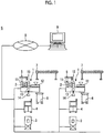
- FIG. 1 is a configuration diagram of an injection molding machine system S according to an embodiment.
- the injection molding machine system S includes an injection molding machine 1, peripheral equipment of the injection molding machine 1, a network 8, and a molding machine management server 9.
- the injection molding machine 1 includes a mold clamping unit 11 that opens and closes a mold unit 2, an ejector unit (not illustrated) that ejects a molding product molded by the mold unit 2, an injection unit 12 that injects a molding material (resin) into the mold unit 2, and a control device 13 that controls each component of the injection molding machine 1.
- the injection unit 12 includes a cylinder, and a heater for plasticizing the molding material is provided in the cylinder.
- the injection molding machine 1 includes an operation unit 14 that receives an input operation of a user and a display unit 15 that displays various information. The information input through the operation unit 14 is input to the control device 13.
- the control device 13 generates a display screen for displaying various information, and displays the display screen on the display unit 15.
- the injection molding machine system S illustrated in FIG. 1 includes a resin dryer 3, a mold temperature controller 4, a take-out machine 5, a crusher 6, and a conveyor 7.
- the resin dryer 3 dries the molding material to be supplied to the injection unit 12.
- the dried molding material is supplied to the injection unit 12 of the injection molding machine 1.
- the mold temperature controller 4 adjusts a temperature of the mold unit 2 to a predetermined temperature. For example, when a flow path is formed in the mold unit 2, the mold temperature controller 4 controls a temperature and/or a flow rate of a heat medium to be supplied to the flow path of the mold unit 2, thereby adjusting the temperature of the mold unit 2 to the predetermined temperature. In addition, when a heater is provided in the mold unit 2, the mold temperature controller 4 controls electric power to be supplied to the heater of the mold unit 2, thereby adjusting the temperature of the mold unit 2 to the predetermined temperature.
- the take-out machine 5 takes out the molding product molded by the mold unit 2, and conveys the molding product to the conveyor 7.
- the take-out machine 5 includes a chuck plate (not illustrated) having a chuck for suctioning the molding product.
- the molding product is accommodated in a product box (not illustrated) of the conveyor 7.
- the crusher 6 crushes a runner generated when the molding product is molded by the mold unit 2.
- the product box (not illustrated) for accommodating the molding product is placed on the conveyor 7.
- the conveyor 7 conveys the product box.
- the peripheral equipment of the injection molding machine 1 is connected to the control device 13 of the injection molding machine 1 to be communicable via the network 8.
- the control device 13 of the injection molding machine 1 is connected to the molding machine management server 9 to be communicable via the network 8.
- the control device 13 of the injection molding machine 1 transmits various information on the injection molding machine 1 to the molding machine management server 9.
- the peripheral equipment of the injection molding machine 1 is connected to the molding machine management server 9 to be communicable via the network 8.
- the peripheral equipment of the injection molding machine 1 transmits various information on the peripheral equipment to the molding machine management server 9.
- the peripheral equipment of the injection molding machine 1 may be configured to transmit various information on the peripheral equipment to the control device 13 of the injection molding machine 1, and to transmit various information on the peripheral equipment to the molding machine management server 9 from the control device 13 of the injection molding machine 1.
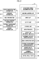
- FIG. 2 is a functional block diagram of a setup supporting device of the injection molding machine 1.
- the setup supporting device of the injection molding machine 1 is installed as one function of the control device 13.
- the control device 13 as the setup supporting device includes a setup work timing determination unit 31, a machine learning unit 32, an input unit 33, an output unit 34, and a storage unit 35.
- the setup work timing determination unit 31 determines a work start time (work start timing) of each setup item, based on input information (information 21 to 26 to be described later) and data (data 41 to 48 described later) stored in advance in the storage unit 35. That is, the setup work timing determination unit 31 prepares a schedule of a setup work by determining the work start time of each setup item.
- the machine learning unit 32 generates learning correction data 47, based on an actual value (actual result data 48 to be described later) of the setup work in the past, and stores the learning correction data 47 in the storage unit 35.
- Input information is input to the input unit 33.
- the information input to the input unit 33 may be information input by the operation unit 14, or may be information transmitted from the peripheral equipment of the injection molding machine 1 or the molding machine management server 9 via the network 8.
- the information may be acquired by a sensor provided in the injection molding machine 1.
- setup completion time information 21, equipment information 22, mold information 23, molding condition information 24, external environment information 25, and worker information 26 are input to the input unit 33.
- the setup completion time information 21 includes a time at which the setup work is completed, in other words, a time at which mass production of the molding product starts.
- the equipment information 22 includes information on the peripheral equipment of the injection molding machine 1.
- the mold information 23 includes information on the mold unit 2 attached to the injection molding machine 1.
- the molding condition information 24 includes information such as a type of the molding material (resin) and temperature raising of the cylinder.
- the external environment information 25 includes information on an external environment (for example, external air temperature or external air humidity) of the injection molding machine 1.
- the worker information 26 includes information on a worker who carries out the setup work.
- the output unit 34 outputs various information.
- the work start time of each generated setup item may be displayed on the display unit 15.
- the output unit 34 may transmit a control signal to directly control each unit of the injection molding machine 1 or the peripheral equipment.
- Various data are stored in advance in the storage unit 35.
- the learning correction data 47 generated by the machine learning unit 32 is stored.
- the actual value of the past setup work of the injection molding machine 1 is stored in the storage unit 35 as the actual result data 48.
- the setup work includes a plurality of items (setup items) .
- setup items of the setup work are stored.
- description will be made on an assumption that the setup items of the setup work have "resin preparation”, “resin drying”, “heater temperature raising”, “mold attachment”, “mold temperature raising”, “crusher preparation”, “conveyor installation”, “product box preparation”, “take-out machine chuck plate attachment”, “take-out machine teaching”, “purge”, and "condition adjustment”.
- the "resin preparation” refers to a work by which the molding material (resin) can be supplied to the resin dryer 3.
- the “resin drying” refers to a work by which the resin dryer 3 is driven to dry the molding material (resin).
- the “heater temperature raising” refers to a work by which the heater of the injection unit 12 is operated to raise the temperature of the cylinder. The molding material inside the cylinder is plasticized by raising the temperature of the cylinder.
- the “mold attachment” refers to a work by which the mold unit 2 is attached to the mold clamping unit 11.
- the “mold temperature raising” refers to a work by which the mold temperature controller 4 is operated to control the temperature of the mold unit 2 to a predetermined temperature.
- the "crusher preparation” refers to a work by which the crusher 6 is brought into an operable state.
- the “conveyor installation” refers to a work by which the conveyor 7 is disposed around the injection molding machine 1 to bring the conveyor 7 into an operable state.
- the “product box preparation” refers to a work by which a product box is prepared on the conveyor 7.
- the “take-out machine chuck plate attachment” refers to a work by which a chuck plate corresponding to the mold unit 2 is attached to the take-out machine 5.
- the “take-out machine teaching” refers to a work for teaching a position of the chuck plate when the molding product is chucked by the take-out machine 5 and a position of the chuck plate when the molding product is accommodated in the product box.
- the “purge” refers to a work by which the molding material (resin) is supplied to the injection unit 12 and is plasticized inside the cylinder so that the molding material (resin) inside the cylinder is purged (discharged).
- the “condition adjustment” refers to a work by which the molding material is injected from the injection unit 12 into the mold unit 2, and while trial molding is performed, molding conditions (a mold clamping force of the mold clamping unit 11, a resin amount of the injection unit 12, and an injection pressure) are adjusted.
- a work sequence may be determined.
- Information indicating the work sequence is stored in the setup item data 41.
- the "resin preparation” is performed prior to the “resin drying” .
- the “mold attachment” is performed prior to the “mold temperature raising” .
- the “mold attachment” is performed prior to the “take-out machine teaching”.
- the “conveyor installation” is performed prior to the “product box preparation”.
- the “take-out machine chuck plate attachment” is performed prior to the “take-out machine teaching”.
- the "heater temperature raising” is performed prior to the "purge” .
- the “purge” is performed prior to the "condition adjustment”.
- the setup items are classified into a setup item in which the worker needs to actually carry out a work (hereinafter, also referred to as a "human work”) and a setup item in which an automatic operation can be performed under the control of the control device 13 (hereinafter, also referred to as an "automatic operation”) .
- the setup item data 41 stores information indicating whether each of the setup items is the human work or the automatic operation.
- the "resin preparation”, the "mold attachment”, the “crusher preparation”, the “conveyor installation”, the “product box preparation”, the “take-out machine chuck plate attachment”, the “take-out machine teaching”, and the “condition adjustment” are the setup items belonging to the human work.
- the “resin drying”, the “heater temperature raising”, the “mold temperature raising”, and the “purge” are the setup items belonging to the automatic operation.
- Each of the setup items described as the human work may be automatically performed in some cases.
- the setup item data 41 may store information indicating the setup items that can be concurrently performed.
- the setup item reference time data 42 stores a reference work time for each of the setup items.
- the equipment capacity correction data 43 stores data for calculating the work time in the setup item in which the work time varies in accordance with the peripheral equipment of the injection molding machine 1.
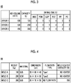
- FIG. 3 illustrates an example of the equipment capacity correction data 43.
- the equipment capacity correction data 43 of the resin dryer 3 is stored.
- the equipment capacity correction data 43 stores an air volume of the resin dryer 3, capacity of the resin dryer 3, and a drying time (work time) for each of the molding materials.
- the mold correction data 44 stores data of the mold unit 2 attached to the mold clamping unit 11 of the injection molding machine 1.
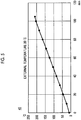
- FIG. 4 illustrates an example of the mold correction data 44.
- the mold correction data 44 stores a weight of the mold unit 2, a material of the mold unit 2, dimensions of the mold unit 2, the presence or absence of a flow path formed in the mold unit 2, a type of the flow path, the presence or absence of the heater provided in the mold unit 2, and a calorific value of the heater.
- a temperature raising time (work time) in the "mold temperature raising" can be calculated by performing heat conduction analysis, based on the mold correction data 44 illustrated in FIG. 4 .
- the external environment correction data 45 stores data for calculating the work time in the setup item in which the work time varies in accordance with the external environment information 25.
- FIG. 5 illustrates an example of the external environment correction data 45.
- the external environment correction data 45 in the "heater temperature raising” is illustrated.
- the external environment correction data 45 stores the temperature raising time and the temperature of the cylinder in association with each other for each external air temperature. Based on the external environment correction data 45 illustrated in FIG. 5 , the temperature raising time (work time) in the "heater temperature raising" can be calculated.
- the worker ability correction data 46 stores data for calculating the work time in the setup item in which the work time varies in accordance with the worker.
- FIG. 6 illustrates an example of the worker ability correction data 46.
- the worker ability correction data 46 in the "take-out machine teaching" is illustrated.
- the worker ability correction data 46 stores qualifications possessed by the worker and years of experience.
- the worker ability correction data 46 stores an average time (work time) required for the teaching of the take-out machine 5 designated based on information on the worker.
- the learning correction data 47 stores data for calculating the work time learned by the machine learning unit 32.
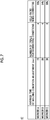
- FIG. 7 illustrates an example of the learning correction data 47.
- the learning correction data 47 in the "condition adjustment" is illustrated.
- the learning correction data 47 stores an average time required for adjusting the molding conditions, the number of trials for correcting conditions, and a yield rate when the conditions are corrected.
- the average time (work time) required for adjusting the molding conditions, the number of trials for correcting the conditions, and the yield rate at when the conditions are corrected are calculated, based on the actual result data 48.
- the actual result data 48 the actual result data of the setup work of the injection molding machine 1 is stored.
- the worker and a time required for each setup item are stored.
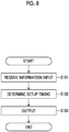
- FIG. 8 is a flowchart illustrating an example of the operation of the setup supporting device.
- the setup work timing determination unit 31 receives an input of input information.
- the worker operates the operation unit 14 to input various information (setup completion time information 21, equipment information 22, mold information 23, external environment information 25, and worker information 26).
- the information input by the operation unit 14 is input to the setup work timing determination unit 31 via the input unit 33.
- the input of various information is not limited to the input of the worker, and may be an input from the molding machine management server 9 via the network 8.
- the setup work timing determination unit 31 calculates a work start timing of each setup item, based on the input information (setup completion time information 21, equipment information 22, mold information 23, molding condition information 24, external environment information 25, worker information 26) and correction data (setup item data 41, setup item reference time data 42, equipment capacity correction data 43, mold correction data 44, external environment correction data 45, worker ability correction data 46, learning correction data 47, and actual result data 48) stored in the storage unit 35.
- the setup work timing determination unit 31 first calculates the work time of each setup item, based on the input information. For example, with reference to the equipment capacity correction data 43 (refer to FIG. 3 ), the setup work timing determination unit 31 calculates the work time of the "resin drying", based on model information on the resin dryer 3 included in the equipment information 22 and a resin name included in the molding condition information 24. With reference to the mold correction data 44 (refer to FIG. 4 ), the setup work timing determination unit 31 calculates the work time of the "mold temperature raising", based on the mold information 23. With reference to the external environment correction data 45 (refer to FIG.
- the setup work timing determination unit 31 calculates the work time of the "heater temperature raising", based on the temperature raising of the cylinder which is included in the molding condition information 24 and the external temperature included in the external environment information 25. With reference to the worker ability correction data 46 (refer to FIG. 6 ), the setup work timing determination unit 31 calculates the work time of the "take-out machine teaching", based on the worker information 26. With reference to the learning correction data 47 (refer to FIG. 7 ), the setup work timing determination unit 31 calculates the work time of the "condition adjustment", based on the worker information 26. In addition, the work time of the "resin preparation" or the "mold attachment" is acquired from the setup item reference time data 42.
- the setup work timing determination unit 31 determines each work start timing of the respective setup items, based on the calculated work time of each setup item, the setup completion time information 21, information indicating a sequence of the setup items of setup item data 41, or information indicating the setup items for which the worker can concurrently carry out the work in the setup item data 41.
- the setup work timing determination unit 31 outputs a work start time (work start timing) of each calculated setup item.
- the setup work timing determination unit 31 causes the display unit 15 to display the work start time of each calculated setup item via the output unit 34.
- the worker can identify the work start time of each setup item.
- the setup item for the human work the worker can carry out the work for each setup item in accordance with the work start time presented on the display unit 15.
- the control device 13 can carry out the work for each setup item in accordance with the determined work start time.
- FIG. 9 illustrates an example of a display screen displayed on the display unit 15.
- An item name of a setup item 201 is displayed on the display screen.
- a time bar 202 of work times (work start time and work end time) of each setup item is displayed.
- the time bar 202 displays a schedule column 202a generated by the setup work timing determination unit 31.
- An actual result column 202b that displays an actual result time may be provided in the time bar 202.
- a comment column 203 corresponding to the item name is provided on the display screen.
- the comment column 203 displays a reason for correcting the work time and a correction time. In this manner, it is possible to easily identify an increase or a decrease from a reference time for each setup item stored in setup item reference time data 42.
- FIG. 10 illustrates an example of the display screen displayed on the display unit 15 after the setup work.
- the actual result column 202b may display the work times (work start time and work end time) of each setup item.
- FIG. 11 illustrates an example of a work timetable for the setup work in a reference example.
- FIG. 11 illustrates that the start time of the "purge” is delayed since the "purge” takes time for the "the take-out machine teaching” due to an inexperienced skill of the worker. As a result, a waiting time is wastefully used after the "resin drying” and the “heater temperature raising".
- the end time of the "purge” and the start time of the "condition adjustment” are also delayed due to a delay in the start time of the "purge”.
- the work time of the "condition adjustment” is further prolonged due to the inexperienced skill of the worker. As a result, the setup work is not completed until 12:00 when mass production starts, and productivity of the injection molding machine 1 is degraded.
- the setup supporting device of the present embodiment corrects the work time and the work start time in each setup step in accordance with equipment capacity, an external environment, mold information, capacity of the worker, or learning data.
- the setup work timing determination unit 31 sets (corrects) the work time of the "resin drying" to be 10 minutes shorter than a normal time (reference time), based on the model information of the resin dryer 3 which is included in the equipment information 22 and a resin name included in the molding condition information 24.
- the external environment correction data 45 (refer to FIG.
- the setup work timing determination unit 31 sets (corrects) the work time of the "heater temperature raising" to be 10 minutes longer than the normal time (reference time), based on the temperature raising of the cylinder included in the molding condition information 24 and the external temperature included in the external environment information 25.
- the setup work timing determination unit 31 sets (corrects) the work time of the "mold temperature raising” to be 10 minutes longer than the normal time (reference time), based on the mold information 23.
- the worker ability correction data 46 (refer to FIG.
- the setup work timing determination unit 31 sets (corrects) the work time of "take-out machine teaching" to be 10 minutes longer than the normal time (reference time), based on the worker information 26.
- the setup work timing determination unit 31 sets (corrects) the work time of the "condition adjustment” to 10 minutes longer than the normal time (reference time), based on the worker information 26.
- the setup work timing determination unit 31 sets the work time of the other setup items to the normal time (reference time) . Then, the setup work timing determination unit 31 calculates the work start timing of each setup item, based on the set work time of each setup item and information indicating a sequence of the work included in the setup item data 41.
- the worker carries out the work in accordance with the generated work start time in each setup item. Accordingly, the worker can efficiency carry out the setup work. In addition, a wasteful waiting time can be reduced. In addition, the setup work can be completed until the mass production starts.
- the setup supporting device according to the present embodiment has been described as an example in which the setup supporting device is installed in the control device 13 of the injection molding machine 1.
- the present invention is not limited thereto.
- a configuration may be adopted in which the setup supporting device is installed in the molding machine management server 9.
Landscapes
- Engineering & Computer Science (AREA)
- Manufacturing & Machinery (AREA)
- Mechanical Engineering (AREA)
- Injection Moulding Of Plastics Or The Like (AREA)
Abstract
Description
- The present invention relate to a setup supporting device and a setup supporting method for an injection molding machine.
- When molding is performed by an injection molding machine, a setup work including a plurality of setup items such as resin preparation, mold attachment, and connection of peripheral equipment is carried out in advance.
- Japanese Unexamined Patent Publication No.
2004-155088 - In the related art, how to carry out a setup work often depends on experience of a worker. Therefore, after a temperature of a cylinder is completely raised or after a resin is completely dried, there is a possibility that a stopped state may be continuously maintained at a raised temperature for a long time without completing other setup items. Consequently, there is a possibility that problems may arise such as wastefully consumed electric power, resin burning, and excessive drying.
- Therefore, embodiments of the present invention aim to provide a setup supporting device and a setup supporting method for an injection molding machine that supports a setup work.
- According to an aspect of the embodiments, there is provided a setup supporting device for an injection molding machine that supports a setup work including a plurality of setup items. The setup supporting device includes a storage unit that stores a table for calculating a work time of the setup items, and a setup work timing determination unit that determines a work start timing of the setup items, based on input information and the table.
- According to the aspect of the present invention, it is possible to provide the setup supporting device and the setup supporting method for the injection molding machine that supports the setup work.
-
-
FIG. 1 is a configuration diagram of an injection molding machine system according to an embodiment. -
FIG. 2 is a functional block diagram of a setup supporting device for an injection molding machine. -
FIG. 3 illustrates an example of equipment capacity correction data. -
FIG. 4 illustrates an example of mold correction data. -
FIG. 5 illustrates an example of external environment correction data. -
FIG. 6 illustrates an example of worker ability correction data. -
FIG. 7 illustrates an example of learning correction data. -
FIG. 8 is a flowchart illustrating an example of an operation of the setup supporting device. -
FIG. 9 illustrates an example of a display screen displayed on a display unit. -
FIG. 10 illustrates an example of a display screen displayed on the display unit after setup work. -
FIG. 11 illustrates an example of a work timetable for setup work in a reference example. - Hereinafter, embodiments according to the present invention will be described with reference to the drawings. In each drawing, the same or corresponding reference numerals will be assigned to the same or corresponding configurations, and description thereof will be omitted.
-
FIG. 1 is a configuration diagram of an injection molding machine system S according to an embodiment. - The injection molding machine system S includes an
injection molding machine 1, peripheral equipment of theinjection molding machine 1, anetwork 8, and a molding machine management server 9. - The
injection molding machine 1 includes amold clamping unit 11 that opens and closes amold unit 2, an ejector unit (not illustrated) that ejects a molding product molded by themold unit 2, aninjection unit 12 that injects a molding material (resin) into themold unit 2, and acontrol device 13 that controls each component of theinjection molding machine 1. Theinjection unit 12 includes a cylinder, and a heater for plasticizing the molding material is provided in the cylinder. In addition, theinjection molding machine 1 includes anoperation unit 14 that receives an input operation of a user and adisplay unit 15 that displays various information. The information input through theoperation unit 14 is input to thecontrol device 13. Thecontrol device 13 generates a display screen for displaying various information, and displays the display screen on thedisplay unit 15. - For example, as peripheral equipment of the
injection molding machine 1, the injection molding machine system S illustrated inFIG. 1 includes aresin dryer 3, amold temperature controller 4, a take-out machine 5, acrusher 6, and aconveyor 7. - The
resin dryer 3 dries the molding material to be supplied to theinjection unit 12. The dried molding material is supplied to theinjection unit 12 of theinjection molding machine 1. - The
mold temperature controller 4 adjusts a temperature of themold unit 2 to a predetermined temperature. For example, when a flow path is formed in themold unit 2, themold temperature controller 4 controls a temperature and/or a flow rate of a heat medium to be supplied to the flow path of themold unit 2, thereby adjusting the temperature of themold unit 2 to the predetermined temperature. In addition, when a heater is provided in themold unit 2, themold temperature controller 4 controls electric power to be supplied to the heater of themold unit 2, thereby adjusting the temperature of themold unit 2 to the predetermined temperature. - The take-
out machine 5 takes out the molding product molded by themold unit 2, and conveys the molding product to theconveyor 7. The take-out machine 5 includes a chuck plate (not illustrated) having a chuck for suctioning the molding product. The molding product is accommodated in a product box (not illustrated) of theconveyor 7. - The
crusher 6 crushes a runner generated when the molding product is molded by themold unit 2. - The product box (not illustrated) for accommodating the molding product is placed on the
conveyor 7. Theconveyor 7 conveys the product box. - The peripheral equipment of the
injection molding machine 1 is connected to thecontrol device 13 of theinjection molding machine 1 to be communicable via thenetwork 8. - The
control device 13 of theinjection molding machine 1 is connected to the molding machine management server 9 to be communicable via thenetwork 8. Thecontrol device 13 of theinjection molding machine 1 transmits various information on theinjection molding machine 1 to the molding machine management server 9. In addition, the peripheral equipment of theinjection molding machine 1 is connected to the molding machine management server 9 to be communicable via thenetwork 8. The peripheral equipment of theinjection molding machine 1 transmits various information on the peripheral equipment to the molding machine management server 9. The peripheral equipment of theinjection molding machine 1 may be configured to transmit various information on the peripheral equipment to thecontrol device 13 of theinjection molding machine 1, and to transmit various information on the peripheral equipment to the molding machine management server 9 from thecontrol device 13 of theinjection molding machine 1. -
FIG. 2 is a functional block diagram of a setup supporting device of theinjection molding machine 1. Here, the setup supporting device of theinjection molding machine 1 is installed as one function of thecontrol device 13. - The
control device 13 as the setup supporting device includes a setup worktiming determination unit 31, amachine learning unit 32, aninput unit 33, anoutput unit 34, and astorage unit 35. - The setup work
timing determination unit 31 determines a work start time (work start timing) of each setup item, based on input information (information 21 to 26 to be described later) and data (data 41 to 48 described later) stored in advance in thestorage unit 35. That is, the setup worktiming determination unit 31 prepares a schedule of a setup work by determining the work start time of each setup item. - The
machine learning unit 32 generateslearning correction data 47, based on an actual value (actual result data 48 to be described later) of the setup work in the past, and stores thelearning correction data 47 in thestorage unit 35. - Input information is input to the
input unit 33. Here, the information input to theinput unit 33 may be information input by theoperation unit 14, or may be information transmitted from the peripheral equipment of theinjection molding machine 1 or the molding machine management server 9 via thenetwork 8. In addition, the information may be acquired by a sensor provided in theinjection molding machine 1. - For example, setup
completion time information 21,equipment information 22,mold information 23,molding condition information 24,external environment information 25, andworker information 26 are input to theinput unit 33. - The setup
completion time information 21 includes a time at which the setup work is completed, in other words, a time at which mass production of the molding product starts. Theequipment information 22 includes information on the peripheral equipment of theinjection molding machine 1. Themold information 23 includes information on themold unit 2 attached to theinjection molding machine 1. Themolding condition information 24 includes information such as a type of the molding material (resin) and temperature raising of the cylinder. Theexternal environment information 25 includes information on an external environment (for example, external air temperature or external air humidity) of theinjection molding machine 1. Theworker information 26 includes information on a worker who carries out the setup work. - The
output unit 34 outputs various information. Here, the work start time of each generated setup item may be displayed on thedisplay unit 15. In addition, theoutput unit 34 may transmit a control signal to directly control each unit of theinjection molding machine 1 or the peripheral equipment. - Various data (
data 41 to 46) are stored in advance in thestorage unit 35. In addition, the learningcorrection data 47 generated by themachine learning unit 32 is stored. In addition, the actual value of the past setup work of theinjection molding machine 1 is stored in thestorage unit 35 as theactual result data 48. - Here, the setup work includes a plurality of items (setup items) . As the
setup item data 41, setup items of the setup work are stored. Here, description will be made on an assumption that the setup items of the setup work have "resin preparation", "resin drying", "heater temperature raising", "mold attachment", "mold temperature raising", "crusher preparation", "conveyor installation", "product box preparation", "take-out machine chuck plate attachment", "take-out machine teaching", "purge", and "condition adjustment". - Here, the "resin preparation" refers to a work by which the molding material (resin) can be supplied to the
resin dryer 3. The "resin drying" refers to a work by which theresin dryer 3 is driven to dry the molding material (resin). The "heater temperature raising" refers to a work by which the heater of theinjection unit 12 is operated to raise the temperature of the cylinder. The molding material inside the cylinder is plasticized by raising the temperature of the cylinder. The "mold attachment" refers to a work by which themold unit 2 is attached to themold clamping unit 11. The "mold temperature raising" refers to a work by which themold temperature controller 4 is operated to control the temperature of themold unit 2 to a predetermined temperature. The "crusher preparation" refers to a work by which thecrusher 6 is brought into an operable state. The "conveyor installation" refers to a work by which theconveyor 7 is disposed around theinjection molding machine 1 to bring theconveyor 7 into an operable state. The "product box preparation" refers to a work by which a product box is prepared on theconveyor 7. The "take-out machine chuck plate attachment" refers to a work by which a chuck plate corresponding to themold unit 2 is attached to the take-outmachine 5. The "take-out machine teaching" refers to a work for teaching a position of the chuck plate when the molding product is chucked by the take-outmachine 5 and a position of the chuck plate when the molding product is accommodated in the product box. The "purge" refers to a work by which the molding material (resin) is supplied to theinjection unit 12 and is plasticized inside the cylinder so that the molding material (resin) inside the cylinder is purged (discharged). The "condition adjustment" refers to a work by which the molding material is injected from theinjection unit 12 into themold unit 2, and while trial molding is performed, molding conditions (a mold clamping force of themold clamping unit 11, a resin amount of theinjection unit 12, and an injection pressure) are adjusted. - In addition, as the setup items, a work sequence may be determined. Information indicating the work sequence is stored in the
setup item data 41. For example, the "resin preparation" is performed prior to the "resin drying" . The "mold attachment" is performed prior to the "mold temperature raising" . The "mold attachment" is performed prior to the "take-out machine teaching". The "conveyor installation" is performed prior to the "product box preparation". The "take-out machine chuck plate attachment" is performed prior to the "take-out machine teaching". The "heater temperature raising" is performed prior to the "purge" . The "purge" is performed prior to the "condition adjustment". - In addition, the setup items are classified into a setup item in which the worker needs to actually carry out a work (hereinafter, also referred to as a "human work") and a setup item in which an automatic operation can be performed under the control of the control device 13 (hereinafter, also referred to as an "automatic operation") . The
setup item data 41 stores information indicating whether each of the setup items is the human work or the automatic operation. For example, the "resin preparation", the "mold attachment", the "crusher preparation", the "conveyor installation", the "product box preparation", the "take-out machine chuck plate attachment", the "take-out machine teaching", and the "condition adjustment" are the setup items belonging to the human work. The "resin drying", the "heater temperature raising", the "mold temperature raising", and the "purge" are the setup items belonging to the automatic operation. Each of the setup items described as the human work may be automatically performed in some cases. - In addition, some of the setup items can be concurrently performed. The
setup item data 41 may store information indicating the setup items that can be concurrently performed. - The setup item
reference time data 42 stores a reference work time for each of the setup items. - The equipment
capacity correction data 43 stores data for calculating the work time in the setup item in which the work time varies in accordance with the peripheral equipment of theinjection molding machine 1.FIG. 3 illustrates an example of the equipmentcapacity correction data 43. Here, as the peripheral equipment of theinjection molding machine 1, the equipmentcapacity correction data 43 of theresin dryer 3 is stored. In the example illustrated inFIG. 3 , for each of theresin dryers 3, the equipmentcapacity correction data 43 stores an air volume of theresin dryer 3, capacity of theresin dryer 3, and a drying time (work time) for each of the molding materials. - The
mold correction data 44 stores data of themold unit 2 attached to themold clamping unit 11 of theinjection molding machine 1.FIG. 4 illustrates an example of themold correction data 44. In the example illustrated inFIG. 4 , for each of themold units 2, themold correction data 44 stores a weight of themold unit 2, a material of themold unit 2, dimensions of themold unit 2, the presence or absence of a flow path formed in themold unit 2, a type of the flow path, the presence or absence of the heater provided in themold unit 2, and a calorific value of the heater. A temperature raising time (work time) in the "mold temperature raising" can be calculated by performing heat conduction analysis, based on themold correction data 44 illustrated inFIG. 4 . - The external
environment correction data 45 stores data for calculating the work time in the setup item in which the work time varies in accordance with theexternal environment information 25.FIG. 5 illustrates an example of the externalenvironment correction data 45. Here, as an example of the setup item in which the work time varies in accordance with theexternal environment information 25, the externalenvironment correction data 45 in the "heater temperature raising" is illustrated. In the example illustrated inFIG. 5 , the externalenvironment correction data 45 stores the temperature raising time and the temperature of the cylinder in association with each other for each external air temperature. Based on the externalenvironment correction data 45 illustrated inFIG. 5 , the temperature raising time (work time) in the "heater temperature raising" can be calculated. - The worker
ability correction data 46 stores data for calculating the work time in the setup item in which the work time varies in accordance with the worker.FIG. 6 illustrates an example of the workerability correction data 46. Here, as an example of the setup item in which the work time varies in accordance with the worker, the workerability correction data 46 in the "take-out machine teaching" is illustrated. In the example illustrated inFIG. 6 , for each worker, the workerability correction data 46 stores qualifications possessed by the worker and years of experience. In addition, the workerability correction data 46 stores an average time (work time) required for the teaching of the take-outmachine 5 designated based on information on the worker. - The learning
correction data 47 stores data for calculating the work time learned by themachine learning unit 32.FIG. 7 illustrates an example of the learningcorrection data 47. Here, the learningcorrection data 47 in the "condition adjustment" is illustrated. In the example illustrated inFIG. 7 , for each worker, the learningcorrection data 47 stores an average time required for adjusting the molding conditions, the number of trials for correcting conditions, and a yield rate when the conditions are corrected. The average time (work time) required for adjusting the molding conditions, the number of trials for correcting the conditions, and the yield rate at when the conditions are corrected are calculated, based on theactual result data 48. - In the
actual result data 48, the actual result data of the setup work of theinjection molding machine 1 is stored. For example, in the setup work, the worker and a time required for each setup item are stored. - Next, an operation of the setup supporting device will be described with reference to
FIG. 8. FIG. 8 is a flowchart illustrating an example of the operation of the setup supporting device. - In Step S101, the setup work
timing determination unit 31 receives an input of input information. Here, the worker operates theoperation unit 14 to input various information (setupcompletion time information 21,equipment information 22,mold information 23,external environment information 25, and worker information 26). The information input by theoperation unit 14 is input to the setup worktiming determination unit 31 via theinput unit 33. The input of various information is not limited to the input of the worker, and may be an input from the molding machine management server 9 via thenetwork 8. - In Step S102, the setup work
timing determination unit 31 calculates a work start timing of each setup item, based on the input information (setupcompletion time information 21,equipment information 22,mold information 23,molding condition information 24,external environment information 25, worker information 26) and correction data (setup item data 41, setup itemreference time data 42, equipmentcapacity correction data 43,mold correction data 44, externalenvironment correction data 45, workerability correction data 46, learningcorrection data 47, and actual result data 48) stored in thestorage unit 35. - Specifically, the setup work
timing determination unit 31 first calculates the work time of each setup item, based on the input information. For example, with reference to the equipment capacity correction data 43 (refer toFIG. 3 ), the setup worktiming determination unit 31 calculates the work time of the "resin drying", based on model information on theresin dryer 3 included in theequipment information 22 and a resin name included in themolding condition information 24. With reference to the mold correction data 44 (refer toFIG. 4 ), the setup worktiming determination unit 31 calculates the work time of the "mold temperature raising", based on themold information 23. With reference to the external environment correction data 45 (refer toFIG. 5 ), the setup worktiming determination unit 31 calculates the work time of the "heater temperature raising", based on the temperature raising of the cylinder which is included in themolding condition information 24 and the external temperature included in theexternal environment information 25. With reference to the worker ability correction data 46 (refer toFIG. 6 ), the setup worktiming determination unit 31 calculates the work time of the "take-out machine teaching", based on theworker information 26. With reference to the learning correction data 47 (refer toFIG. 7 ), the setup worktiming determination unit 31 calculates the work time of the "condition adjustment", based on theworker information 26. In addition, the work time of the "resin preparation" or the "mold attachment" is acquired from the setup itemreference time data 42. - Next, the setup work
timing determination unit 31 determines each work start timing of the respective setup items, based on the calculated work time of each setup item, the setupcompletion time information 21, information indicating a sequence of the setup items ofsetup item data 41, or information indicating the setup items for which the worker can concurrently carry out the work in thesetup item data 41. - In Step S103, the setup work
timing determination unit 31 outputs a work start time (work start timing) of each calculated setup item. For example, the setup worktiming determination unit 31 causes thedisplay unit 15 to display the work start time of each calculated setup item via theoutput unit 34. In this manner, the worker can identify the work start time of each setup item. In addition, with regard to the setup item for the human work, the worker can carry out the work for each setup item in accordance with the work start time presented on thedisplay unit 15. In addition, with regard to the setup item for the automatic operation, thecontrol device 13 can carry out the work for each setup item in accordance with the determined work start time. -
FIG. 9 illustrates an example of a display screen displayed on thedisplay unit 15. An item name of asetup item 201 is displayed on the display screen. Corresponding to the item name, in a next column of a column of the setup item 201 (next column on the right inFIG. 9 ), atime bar 202 of work times (work start time and work end time) of each setup item is displayed. In addition, thetime bar 202 displays aschedule column 202a generated by the setup worktiming determination unit 31. Anactual result column 202b that displays an actual result time may be provided in thetime bar 202. In addition, acomment column 203 corresponding to the item name is provided on the display screen. Thecomment column 203 displays a reason for correcting the work time and a correction time. In this manner, it is possible to easily identify an increase or a decrease from a reference time for each setup item stored in setup itemreference time data 42. -
FIG. 10 illustrates an example of the display screen displayed on thedisplay unit 15 after the setup work. As illustrated inFIG. 10 , theactual result column 202b may display the work times (work start time and work end time) of each setup item. - Here,
FIG. 11 illustrates an example of a work timetable for the setup work in a reference example. Here,FIG. 11 illustrates that the start time of the "purge" is delayed since the "purge" takes time for the "the take-out machine teaching" due to an inexperienced skill of the worker. As a result, a waiting time is wastefully used after the "resin drying" and the "heater temperature raising". In addition, it will be understood that the end time of the "purge" and the start time of the "condition adjustment" are also delayed due to a delay in the start time of the "purge". In addition, the work time of the "condition adjustment" is further prolonged due to the inexperienced skill of the worker. As a result, the setup work is not completed until 12:00 when mass production starts, and productivity of theinjection molding machine 1 is degraded. - In contrast, as illustrated in
FIG. 10 , the setup supporting device of the present embodiment corrects the work time and the work start time in each setup step in accordance with equipment capacity, an external environment, mold information, capacity of the worker, or learning data. Specifically, in the example illustrated inFIG. 10 , with reference to the equipment capacity correction data 43 (refer toFIG. 3 ), the setup worktiming determination unit 31 sets (corrects) the work time of the "resin drying" to be 10 minutes shorter than a normal time (reference time), based on the model information of theresin dryer 3 which is included in theequipment information 22 and a resin name included in themolding condition information 24. In addition, with reference to the external environment correction data 45 (refer toFIG. 5 ), the setup worktiming determination unit 31 sets (corrects) the work time of the "heater temperature raising" to be 10 minutes longer than the normal time (reference time), based on the temperature raising of the cylinder included in themolding condition information 24 and the external temperature included in theexternal environment information 25. In addition, with reference to the mold correction data 44 (refer toFIG. 4 ), the setup worktiming determination unit 31 sets (corrects) the work time of the "mold temperature raising" to be 10 minutes longer than the normal time (reference time), based on themold information 23. In addition, with reference to the worker ability correction data 46 (refer toFIG. 6 ), the setup worktiming determination unit 31 sets (corrects) the work time of "take-out machine teaching" to be 10 minutes longer than the normal time (reference time), based on theworker information 26. In addition, with reference to the learning correction data 47 (refer toFIG. 7 ), the setup worktiming determination unit 31 sets (corrects) the work time of the "condition adjustment" to 10 minutes longer than the normal time (reference time), based on theworker information 26. The setup worktiming determination unit 31 sets the work time of the other setup items to the normal time (reference time) . Then, the setup worktiming determination unit 31 calculates the work start timing of each setup item, based on the set work time of each setup item and information indicating a sequence of the work included in thesetup item data 41. In this manner, the worker carries out the work in accordance with the generated work start time in each setup item. Accordingly, the worker can efficiency carry out the setup work. In addition, a wasteful waiting time can be reduced. In addition, the setup work can be completed until the mass production starts. - Hitherto, the embodiments of the
injection molding machine 1 have been described. However, the present invention is not limited to the above-described embodiments. Various modifications and improvements can be made within the scope of the concept of the present invention described in the appended claims. - The setup supporting device according to the present embodiment has been described as an example in which the setup supporting device is installed in the
control device 13 of theinjection molding machine 1. However, the present invention is not limited thereto. A configuration may be adopted in which the setup supporting device is installed in the molding machine management server 9. -
- S injection molding machine system
- 1 Injection molding machine
- 2 mold unit
- 3 resin dryer
- 4 mold temperature controller
- 5 take-out machine
- 6 crusher
- 7 conveyor
- 8 network
- 9 molding machine management server
- 11 mold clamping unit
- 12 injection unit
- 13 control device
- 14 operation unit
- 15 display unit
- 21 setup completion time information
- 22 equipment information (input information)
- 23 mold information (input information)
- 24 molding condition information (input information)
- 25 external environment information (input information)
- 26 worker information (input information)
- 31 setup work timing determination unit
- 32 machine learning unit (learning unit)
- 33 input unit
- 34 output unit
- 35 storage unit
- 41 setup item data
- 42 setup item reference time data
- 43 equipment capacity correction data (table)
- 44 mold correction data (table)
- 45 external environment correction data (table)
- 46 worker ability correction data (table)
- 47 learning correction data (table)
- 48 actual result data (table)
Claims (5)
- A setup supporting device for an injection molding machine (1) that supports a setup work including a plurality of setup items, the device comprising:a storage unit (35) that stores a table (43, 44, 45, 46, 47, 48) for calculating a work time of the setup items; anda setup work timing determination unit (31) that determines a work start timing of the setup items, based on input information and the table (43, 44, 45, 46, 47, 48).
- The setup supporting device for an injection molding machine (1) according to claim 1,
wherein the setup work timing determination unit determines a work procedure of the setup items. - The setup supporting device for an injection molding machine (1) according to claim 1 or 2,
wherein the input information includes at least one of equipment information (22), mold information (23), molding condition information (24), external environment information (25), and worker information (26) of the injection molding machine (1). - The setup supporting device for an injection molding machine (1) according to any one of claims 1 to 3, further comprising:
a learning unit (32) that corrects the table (43, 44, 45, 46, 47, 48), based on an actual value of the setup work. - A setup supporting method for supporting a setup work including a plurality of setup items, the method comprising:a step of inputting input information; anda step of determining a work start timing of the setup items, based on the input information and a table (43, 44, 45, 46, 47, 48) for calculating a work time of the setup items.
Applications Claiming Priority (1)
| Application Number | Priority Date | Filing Date | Title |
|---|---|---|---|
| JP2020065114A JP7460428B2 (en) | 2020-03-31 | 2020-03-31 | Setup support device and setup support method for injection molding machine |
Publications (2)
| Publication Number | Publication Date |
|---|---|
| EP3888877A1 true EP3888877A1 (en) | 2021-10-06 |
| EP3888877B1 EP3888877B1 (en) | 2022-12-21 |
Family
ID=75143454
Family Applications (1)
| Application Number | Title | Priority Date | Filing Date |
|---|---|---|---|
| EP21163848.1A Active EP3888877B1 (en) | 2020-03-31 | 2021-03-22 | Setup supporting device and setup supporting method for injection molding machine |
Country Status (3)
| Country | Link |
|---|---|
| EP (1) | EP3888877B1 (en) |
| JP (1) | JP7460428B2 (en) |
| CN (1) | CN113459451B (en) |
Families Citing this family (2)
| Publication number | Priority date | Publication date | Assignee | Title |
|---|---|---|---|---|
| US12157258B2 (en) * | 2020-08-25 | 2024-12-03 | Kabushiki Kaisha Harmo | Molded product take-out apparatus |
| JP7781495B2 (en) * | 2022-02-07 | 2025-12-08 | Yushin株式会社 | Molded Product Manufacturing System |
Citations (4)
| Publication number | Priority date | Publication date | Assignee | Title |
|---|---|---|---|---|
| US20030154004A1 (en) * | 1999-07-21 | 2003-08-14 | Kroeger Charles R. | Closed loop interactive controller |
| JP2004155088A (en) | 2002-11-07 | 2004-06-03 | Nissei Plastics Ind Co | Program support method for injection molding machine |
| US20130253696A1 (en) * | 2010-12-14 | 2013-09-26 | Husky Injection Molding Systems Ltd. | Thermal Management of Molding System |
| JP2017170776A (en) * | 2016-03-24 | 2017-09-28 | 株式会社トーエネック | Operation support system for resin molding factory, computer program therefor, computer-readable recording medium storing the program, and operation support method for resin molding factory |
Family Cites Families (14)
| Publication number | Priority date | Publication date | Assignee | Title |
|---|---|---|---|---|
| JPH04199401A (en) * | 1990-11-29 | 1992-07-20 | Sekisui Chem Co Ltd | Molding process control system |
| JPH0612544A (en) * | 1992-06-25 | 1994-01-21 | Kao Corp | Operating process prediction device |
| JP2530546B2 (en) * | 1992-09-30 | 1996-09-04 | 有限会社佐倉プラスチック工業 | Automatic operation system in injection molding |
| JPH06254932A (en) * | 1993-03-02 | 1994-09-13 | Ricoh Co Ltd | Management system for injection molding processing system |
| JP2810841B2 (en) * | 1993-07-15 | 1998-10-15 | 松下電工株式会社 | Creating a production plan for the molding process |
| JP4579863B2 (en) * | 2006-05-19 | 2010-11-10 | ファナック株式会社 | Display device, injection molding machine, management device for injection molding machine |
| JP4177399B2 (en) * | 2006-10-27 | 2008-11-05 | 日精樹脂工業株式会社 | Control method of injection molding machine |
| AT10596U1 (en) * | 2008-02-26 | 2009-06-15 | Keba Ag | CONFIGURATION OF MACHINE RUNS |
| JP5653599B2 (en) * | 2008-08-29 | 2015-01-14 | 住友重機械工業株式会社 | Molding condition setting screen, molding condition setting device, and molding condition setting method |
| CN101591730B (en) * | 2009-07-01 | 2011-08-31 | 东北大学 | Method and device for improving operating efficiency of material handling equipment of bell type furnace units of steel enterprises |
| JP5346840B2 (en) * | 2010-02-17 | 2013-11-20 | 日精樹脂工業株式会社 | Setup support method and apparatus for injection molding machine |
| JP2017154311A (en) * | 2016-02-29 | 2017-09-07 | 住友重機械工業株式会社 | Injection molding machine |
| CN109262963A (en) * | 2018-09-27 | 2019-01-25 | 南京塑维网络科技有限公司 | It is a kind of for being molded the Workforce Management and method of production line |
| CN109359884B (en) * | 2018-10-31 | 2021-07-27 | 南京航空航天大学 | Workshop operation plan and rescheduling method for complex aviation equipment structure |
-
2020
- 2020-03-31 JP JP2020065114A patent/JP7460428B2/en active Active
-
2021
- 2021-01-05 CN CN202110005360.0A patent/CN113459451B/en active Active
- 2021-03-22 EP EP21163848.1A patent/EP3888877B1/en active Active
Patent Citations (4)
| Publication number | Priority date | Publication date | Assignee | Title |
|---|---|---|---|---|
| US20030154004A1 (en) * | 1999-07-21 | 2003-08-14 | Kroeger Charles R. | Closed loop interactive controller |
| JP2004155088A (en) | 2002-11-07 | 2004-06-03 | Nissei Plastics Ind Co | Program support method for injection molding machine |
| US20130253696A1 (en) * | 2010-12-14 | 2013-09-26 | Husky Injection Molding Systems Ltd. | Thermal Management of Molding System |
| JP2017170776A (en) * | 2016-03-24 | 2017-09-28 | 株式会社トーエネック | Operation support system for resin molding factory, computer program therefor, computer-readable recording medium storing the program, and operation support method for resin molding factory |
Also Published As
| Publication number | Publication date |
|---|---|
| EP3888877B1 (en) | 2022-12-21 |
| JP2021160279A (en) | 2021-10-11 |
| CN113459451B (en) | 2023-06-13 |
| JP7460428B2 (en) | 2024-04-02 |
| CN113459451A (en) | 2021-10-01 |
Similar Documents
| Publication | Publication Date | Title |
|---|---|---|
| EP3888877B1 (en) | Setup supporting device and setup supporting method for injection molding machine | |
| US20200103862A1 (en) | Deterioration determining apparatus and deterioration determining system | |
| US20160101559A1 (en) | Injection molding machine including a plurality of injection units | |
| JP2007537537A (en) | Improved temperature control | |
| JP2004318262A (en) | Management support apparatus, and system, method, program thereof, and recording medium recording program | |
| KR20140091991A (en) | A Molding Information Extraction Symtem of Emitting Mold Press | |
| JPH06180613A (en) | Heating temperature controller | |
| US20230364842A1 (en) | Molding condition setting device and molding condition setting method | |
| US20060235568A1 (en) | Display controller for injection molding machine | |
| JP7530687B2 (en) | Information processing device, information processing system, and program | |
| US20220080634A1 (en) | Method for viewing and selecting production resources, in particular peripheral devices, for the injection molding industry, and an industrial installation | |
| JP2010000717A (en) | Molding machine management device and molding machine management method | |
| JP2020157705A (en) | Injection molding system | |
| JP2020082701A (en) | Injection molding device system | |
| CN108284585A (en) | A kind of inflation film manufacturing machine automatically controls film blowing method | |
| JP2020131629A (en) | Molded product take-out device | |
| US8865035B2 (en) | Method for controlling RF energy applied to molds | |
| JP7216434B2 (en) | Molded product take-out device | |
| JP5360182B2 (en) | Resin sealing device and control method of resin sealing device | |
| US12157258B2 (en) | Molded product take-out apparatus | |
| JPH06190887A (en) | Molding machine with function to analyze the cause of defects in molded products | |
| CN112566768A (en) | Hot runner device | |
| JP2004155125A (en) | Display method for molding data of molding machine and molding data control system | |
| JP2010076432A (en) | Molding condition setting screen, molding condition setting apparatus, and molding condition setting method | |
| KR20170101607A (en) | Method for manufacturing a product using injection molding device |
Legal Events
| Date | Code | Title | Description |
|---|---|---|---|
| PUAI | Public reference made under article 153(3) epc to a published international application that has entered the european phase |
Free format text: ORIGINAL CODE: 0009012 |
|
| STAA | Information on the status of an ep patent application or granted ep patent |
Free format text: STATUS: REQUEST FOR EXAMINATION WAS MADE |
|
| STAA | Information on the status of an ep patent application or granted ep patent |
Free format text: STATUS: EXAMINATION IS IN PROGRESS |
|
| 17P | Request for examination filed |
Effective date: 20210322 |
|
| AK | Designated contracting states |
Kind code of ref document: A1 Designated state(s): AL AT BE BG CH CY CZ DE DK EE ES FI FR GB GR HR HU IE IS IT LI LT LU LV MC MK MT NL NO PL PT RO RS SE SI SK SM TR |
|
| 17Q | First examination report despatched |
Effective date: 20210914 |
|
| GRAP | Despatch of communication of intention to grant a patent |
Free format text: ORIGINAL CODE: EPIDOSNIGR1 |
|
| STAA | Information on the status of an ep patent application or granted ep patent |
Free format text: STATUS: GRANT OF PATENT IS INTENDED |
|
| INTG | Intention to grant announced |
Effective date: 20220711 |
|
| GRAS | Grant fee paid |
Free format text: ORIGINAL CODE: EPIDOSNIGR3 |
|
| GRAA | (expected) grant |
Free format text: ORIGINAL CODE: 0009210 |
|
| STAA | Information on the status of an ep patent application or granted ep patent |
Free format text: STATUS: THE PATENT HAS BEEN GRANTED |
|
| AK | Designated contracting states |
Kind code of ref document: B1 Designated state(s): AL AT BE BG CH CY CZ DE DK EE ES FI FR GB GR HR HU IE IS IT LI LT LU LV MC MK MT NL NO PL PT RO RS SE SI SK SM TR |
|
| REG | Reference to a national code |
Ref country code: GB Ref legal event code: FG4D |
|
| REG | Reference to a national code |
Ref country code: DE Ref legal event code: R096 Ref document number: 602021001018 Country of ref document: DE |
|
| REG | Reference to a national code |
Ref country code: CH Ref legal event code: EP |
|
| REG | Reference to a national code |
Ref country code: AT Ref legal event code: REF Ref document number: 1538783 Country of ref document: AT Kind code of ref document: T Effective date: 20230115 |
|
| REG | Reference to a national code |
Ref country code: IE Ref legal event code: FG4D |
|
| REG | Reference to a national code |
Ref country code: LT Ref legal event code: MG9D |
|
| REG | Reference to a national code |
Ref country code: NL Ref legal event code: MP Effective date: 20221221 |
|
| PG25 | Lapsed in a contracting state [announced via postgrant information from national office to epo] |
Ref country code: SE Free format text: LAPSE BECAUSE OF FAILURE TO SUBMIT A TRANSLATION OF THE DESCRIPTION OR TO PAY THE FEE WITHIN THE PRESCRIBED TIME-LIMIT Effective date: 20221221 Ref country code: NO Free format text: LAPSE BECAUSE OF FAILURE TO SUBMIT A TRANSLATION OF THE DESCRIPTION OR TO PAY THE FEE WITHIN THE PRESCRIBED TIME-LIMIT Effective date: 20230321 Ref country code: LT Free format text: LAPSE BECAUSE OF FAILURE TO SUBMIT A TRANSLATION OF THE DESCRIPTION OR TO PAY THE FEE WITHIN THE PRESCRIBED TIME-LIMIT Effective date: 20221221 Ref country code: FI Free format text: LAPSE BECAUSE OF FAILURE TO SUBMIT A TRANSLATION OF THE DESCRIPTION OR TO PAY THE FEE WITHIN THE PRESCRIBED TIME-LIMIT Effective date: 20221221 |
|
| REG | Reference to a national code |
Ref country code: AT Ref legal event code: MK05 Ref document number: 1538783 Country of ref document: AT Kind code of ref document: T Effective date: 20221221 |
|
| PG25 | Lapsed in a contracting state [announced via postgrant information from national office to epo] |
Ref country code: RS Free format text: LAPSE BECAUSE OF FAILURE TO SUBMIT A TRANSLATION OF THE DESCRIPTION OR TO PAY THE FEE WITHIN THE PRESCRIBED TIME-LIMIT Effective date: 20221221 Ref country code: LV Free format text: LAPSE BECAUSE OF FAILURE TO SUBMIT A TRANSLATION OF THE DESCRIPTION OR TO PAY THE FEE WITHIN THE PRESCRIBED TIME-LIMIT Effective date: 20221221 Ref country code: HR Free format text: LAPSE BECAUSE OF FAILURE TO SUBMIT A TRANSLATION OF THE DESCRIPTION OR TO PAY THE FEE WITHIN THE PRESCRIBED TIME-LIMIT Effective date: 20221221 Ref country code: GR Free format text: LAPSE BECAUSE OF FAILURE TO SUBMIT A TRANSLATION OF THE DESCRIPTION OR TO PAY THE FEE WITHIN THE PRESCRIBED TIME-LIMIT Effective date: 20230322 |
|
| PG25 | Lapsed in a contracting state [announced via postgrant information from national office to epo] |
Ref country code: NL Free format text: LAPSE BECAUSE OF FAILURE TO SUBMIT A TRANSLATION OF THE DESCRIPTION OR TO PAY THE FEE WITHIN THE PRESCRIBED TIME-LIMIT Effective date: 20221221 |
|
| PG25 | Lapsed in a contracting state [announced via postgrant information from national office to epo] |
Ref country code: SM Free format text: LAPSE BECAUSE OF FAILURE TO SUBMIT A TRANSLATION OF THE DESCRIPTION OR TO PAY THE FEE WITHIN THE PRESCRIBED TIME-LIMIT Effective date: 20221221 Ref country code: RO Free format text: LAPSE BECAUSE OF FAILURE TO SUBMIT A TRANSLATION OF THE DESCRIPTION OR TO PAY THE FEE WITHIN THE PRESCRIBED TIME-LIMIT Effective date: 20221221 Ref country code: PT Free format text: LAPSE BECAUSE OF FAILURE TO SUBMIT A TRANSLATION OF THE DESCRIPTION OR TO PAY THE FEE WITHIN THE PRESCRIBED TIME-LIMIT Effective date: 20230421 Ref country code: ES Free format text: LAPSE BECAUSE OF FAILURE TO SUBMIT A TRANSLATION OF THE DESCRIPTION OR TO PAY THE FEE WITHIN THE PRESCRIBED TIME-LIMIT Effective date: 20221221 Ref country code: EE Free format text: LAPSE BECAUSE OF FAILURE TO SUBMIT A TRANSLATION OF THE DESCRIPTION OR TO PAY THE FEE WITHIN THE PRESCRIBED TIME-LIMIT Effective date: 20221221 Ref country code: CZ Free format text: LAPSE BECAUSE OF FAILURE TO SUBMIT A TRANSLATION OF THE DESCRIPTION OR TO PAY THE FEE WITHIN THE PRESCRIBED TIME-LIMIT Effective date: 20221221 Ref country code: AT Free format text: LAPSE BECAUSE OF FAILURE TO SUBMIT A TRANSLATION OF THE DESCRIPTION OR TO PAY THE FEE WITHIN THE PRESCRIBED TIME-LIMIT Effective date: 20221221 |
|
| PG25 | Lapsed in a contracting state [announced via postgrant information from national office to epo] |
Ref country code: SK Free format text: LAPSE BECAUSE OF FAILURE TO SUBMIT A TRANSLATION OF THE DESCRIPTION OR TO PAY THE FEE WITHIN THE PRESCRIBED TIME-LIMIT Effective date: 20221221 Ref country code: PL Free format text: LAPSE BECAUSE OF FAILURE TO SUBMIT A TRANSLATION OF THE DESCRIPTION OR TO PAY THE FEE WITHIN THE PRESCRIBED TIME-LIMIT Effective date: 20221221 Ref country code: IS Free format text: LAPSE BECAUSE OF FAILURE TO SUBMIT A TRANSLATION OF THE DESCRIPTION OR TO PAY THE FEE WITHIN THE PRESCRIBED TIME-LIMIT Effective date: 20230421 Ref country code: AL Free format text: LAPSE BECAUSE OF FAILURE TO SUBMIT A TRANSLATION OF THE DESCRIPTION OR TO PAY THE FEE WITHIN THE PRESCRIBED TIME-LIMIT Effective date: 20221221 |
|
| REG | Reference to a national code |
Ref country code: DE Ref legal event code: R097 Ref document number: 602021001018 Country of ref document: DE |
|
| PLBE | No opposition filed within time limit |
Free format text: ORIGINAL CODE: 0009261 |
|
| STAA | Information on the status of an ep patent application or granted ep patent |
Free format text: STATUS: NO OPPOSITION FILED WITHIN TIME LIMIT |
|
| PG25 | Lapsed in a contracting state [announced via postgrant information from national office to epo] |
Ref country code: MC Free format text: LAPSE BECAUSE OF FAILURE TO SUBMIT A TRANSLATION OF THE DESCRIPTION OR TO PAY THE FEE WITHIN THE PRESCRIBED TIME-LIMIT Effective date: 20221221 Ref country code: DK Free format text: LAPSE BECAUSE OF FAILURE TO SUBMIT A TRANSLATION OF THE DESCRIPTION OR TO PAY THE FEE WITHIN THE PRESCRIBED TIME-LIMIT Effective date: 20221221 |
|
| 26N | No opposition filed |
Effective date: 20230922 |
|
| REG | Reference to a national code |
Ref country code: BE Ref legal event code: MM Effective date: 20230331 |
|
| PG25 | Lapsed in a contracting state [announced via postgrant information from national office to epo] |
Ref country code: LU Free format text: LAPSE BECAUSE OF NON-PAYMENT OF DUE FEES Effective date: 20230322 |
|
| REG | Reference to a national code |
Ref country code: IE Ref legal event code: MM4A |
|
| PG25 | Lapsed in a contracting state [announced via postgrant information from national office to epo] |
Ref country code: SI Free format text: LAPSE BECAUSE OF FAILURE TO SUBMIT A TRANSLATION OF THE DESCRIPTION OR TO PAY THE FEE WITHIN THE PRESCRIBED TIME-LIMIT Effective date: 20221221 Ref country code: IE Free format text: LAPSE BECAUSE OF NON-PAYMENT OF DUE FEES Effective date: 20230322 Ref country code: FR Free format text: LAPSE BECAUSE OF NON-PAYMENT OF DUE FEES Effective date: 20230331 |
|
| PG25 | Lapsed in a contracting state [announced via postgrant information from national office to epo] |
Ref country code: BE Free format text: LAPSE BECAUSE OF NON-PAYMENT OF DUE FEES Effective date: 20230331 |
|
| PG25 | Lapsed in a contracting state [announced via postgrant information from national office to epo] |
Ref country code: IT Free format text: LAPSE BECAUSE OF FAILURE TO SUBMIT A TRANSLATION OF THE DESCRIPTION OR TO PAY THE FEE WITHIN THE PRESCRIBED TIME-LIMIT Effective date: 20221221 |
|
| REG | Reference to a national code |
Ref country code: CH Ref legal event code: PL |
|
| PG25 | Lapsed in a contracting state [announced via postgrant information from national office to epo] |
Ref country code: BG Free format text: LAPSE BECAUSE OF FAILURE TO SUBMIT A TRANSLATION OF THE DESCRIPTION OR TO PAY THE FEE WITHIN THE PRESCRIBED TIME-LIMIT Effective date: 20221221 |
|
| PG25 | Lapsed in a contracting state [announced via postgrant information from national office to epo] |
Ref country code: BG Free format text: LAPSE BECAUSE OF FAILURE TO SUBMIT A TRANSLATION OF THE DESCRIPTION OR TO PAY THE FEE WITHIN THE PRESCRIBED TIME-LIMIT Effective date: 20221221 |
|
| PG25 | Lapsed in a contracting state [announced via postgrant information from national office to epo] |
Ref country code: CH Free format text: LAPSE BECAUSE OF NON-PAYMENT OF DUE FEES Effective date: 20240331 |
|
| PG25 | Lapsed in a contracting state [announced via postgrant information from national office to epo] |
Ref country code: CY Free format text: LAPSE BECAUSE OF FAILURE TO SUBMIT A TRANSLATION OF THE DESCRIPTION OR TO PAY THE FEE WITHIN THE PRESCRIBED TIME-LIMIT; INVALID AB INITIO Effective date: 20210322 |
|
| PG25 | Lapsed in a contracting state [announced via postgrant information from national office to epo] |
Ref country code: HU Free format text: LAPSE BECAUSE OF FAILURE TO SUBMIT A TRANSLATION OF THE DESCRIPTION OR TO PAY THE FEE WITHIN THE PRESCRIBED TIME-LIMIT; INVALID AB INITIO Effective date: 20210322 |
|
| GBPC | Gb: european patent ceased through non-payment of renewal fee |
Effective date: 20250322 |
|
| PG25 | Lapsed in a contracting state [announced via postgrant information from national office to epo] |
Ref country code: TR Free format text: LAPSE BECAUSE OF FAILURE TO SUBMIT A TRANSLATION OF THE DESCRIPTION OR TO PAY THE FEE WITHIN THE PRESCRIBED TIME-LIMIT Effective date: 20221221 |
|
| PG25 | Lapsed in a contracting state [announced via postgrant information from national office to epo] |
Ref country code: GB Free format text: LAPSE BECAUSE OF NON-PAYMENT OF DUE FEES Effective date: 20250322 |
|
| PGFP | Annual fee paid to national office [announced via postgrant information from national office to epo] |
Ref country code: DE Payment date: 20260128 Year of fee payment: 6 |