EP3888837A1 - Laser marker - Google Patents
Laser marker Download PDFInfo
- Publication number
- EP3888837A1 EP3888837A1 EP19888438.9A EP19888438A EP3888837A1 EP 3888837 A1 EP3888837 A1 EP 3888837A1 EP 19888438 A EP19888438 A EP 19888438A EP 3888837 A1 EP3888837 A1 EP 3888837A1
- Authority
- EP
- European Patent Office
- Prior art keywords
- housing
- rotation position
- sensor
- case
- laser light
- Prior art date
- Legal status (The legal status is an assumption and is not a legal conclusion. Google has not performed a legal analysis and makes no representation as to the accuracy of the status listed.)
- Granted
Links
Images








Classifications
-
- B—PERFORMING OPERATIONS; TRANSPORTING
- B23—MACHINE TOOLS; METAL-WORKING NOT OTHERWISE PROVIDED FOR
- B23K—SOLDERING OR UNSOLDERING; WELDING; CLADDING OR PLATING BY SOLDERING OR WELDING; CUTTING BY APPLYING HEAT LOCALLY, e.g. FLAME CUTTING; WORKING BY LASER BEAM
- B23K26/00—Working by laser beam, e.g. welding, cutting or boring
- B23K26/70—Auxiliary operations or equipment
- B23K26/702—Auxiliary equipment
- B23K26/707—Auxiliary equipment for monitoring laser beam transmission optics
-
- G—PHYSICS
- G06—COMPUTING OR CALCULATING; COUNTING
- G06K—GRAPHICAL DATA READING; PRESENTATION OF DATA; RECORD CARRIERS; HANDLING RECORD CARRIERS
- G06K1/00—Methods or arrangements for marking the record carrier in digital fashion
- G06K1/12—Methods or arrangements for marking the record carrier in digital fashion otherwise than by punching
- G06K1/126—Methods or arrangements for marking the record carrier in digital fashion otherwise than by punching by photographic or thermographic registration
-
- B—PERFORMING OPERATIONS; TRANSPORTING
- B23—MACHINE TOOLS; METAL-WORKING NOT OTHERWISE PROVIDED FOR
- B23K—SOLDERING OR UNSOLDERING; WELDING; CLADDING OR PLATING BY SOLDERING OR WELDING; CUTTING BY APPLYING HEAT LOCALLY, e.g. FLAME CUTTING; WORKING BY LASER BEAM
- B23K26/00—Working by laser beam, e.g. welding, cutting or boring
- B23K26/08—Devices involving relative movement between laser beam and workpiece
- B23K26/082—Scanning systems, i.e. devices involving movement of the laser beam relative to the laser head
-
- B—PERFORMING OPERATIONS; TRANSPORTING
- B23—MACHINE TOOLS; METAL-WORKING NOT OTHERWISE PROVIDED FOR
- B23K—SOLDERING OR UNSOLDERING; WELDING; CLADDING OR PLATING BY SOLDERING OR WELDING; CUTTING BY APPLYING HEAT LOCALLY, e.g. FLAME CUTTING; WORKING BY LASER BEAM
- B23K26/00—Working by laser beam, e.g. welding, cutting or boring
- B23K26/08—Devices involving relative movement between laser beam and workpiece
- B23K26/10—Devices involving relative movement between laser beam and workpiece using a fixed support, i.e. involving moving the laser beam
- B23K26/103—Devices involving relative movement between laser beam and workpiece using a fixed support, i.e. involving moving the laser beam the laser beam rotating around the fixed workpiece
-
- B—PERFORMING OPERATIONS; TRANSPORTING
- B23—MACHINE TOOLS; METAL-WORKING NOT OTHERWISE PROVIDED FOR
- B23K—SOLDERING OR UNSOLDERING; WELDING; CLADDING OR PLATING BY SOLDERING OR WELDING; CUTTING BY APPLYING HEAT LOCALLY, e.g. FLAME CUTTING; WORKING BY LASER BEAM
- B23K26/00—Working by laser beam, e.g. welding, cutting or boring
- B23K26/352—Working by laser beam, e.g. welding, cutting or boring for surface treatment
- B23K26/355—Texturing
-
- B—PERFORMING OPERATIONS; TRANSPORTING
- B23—MACHINE TOOLS; METAL-WORKING NOT OTHERWISE PROVIDED FOR
- B23K—SOLDERING OR UNSOLDERING; WELDING; CLADDING OR PLATING BY SOLDERING OR WELDING; CUTTING BY APPLYING HEAT LOCALLY, e.g. FLAME CUTTING; WORKING BY LASER BEAM
- B23K26/00—Working by laser beam, e.g. welding, cutting or boring
- B23K26/36—Removing material
- B23K26/362—Laser etching
-
- B—PERFORMING OPERATIONS; TRANSPORTING
- B23—MACHINE TOOLS; METAL-WORKING NOT OTHERWISE PROVIDED FOR
- B23K—SOLDERING OR UNSOLDERING; WELDING; CLADDING OR PLATING BY SOLDERING OR WELDING; CUTTING BY APPLYING HEAT LOCALLY, e.g. FLAME CUTTING; WORKING BY LASER BEAM
- B23K26/00—Working by laser beam, e.g. welding, cutting or boring
- B23K26/70—Auxiliary operations or equipment
- B23K26/702—Auxiliary equipment
- B23K26/706—Protective screens
-
- B—PERFORMING OPERATIONS; TRANSPORTING
- B23—MACHINE TOOLS; METAL-WORKING NOT OTHERWISE PROVIDED FOR
- B23K—SOLDERING OR UNSOLDERING; WELDING; CLADDING OR PLATING BY SOLDERING OR WELDING; CUTTING BY APPLYING HEAT LOCALLY, e.g. FLAME CUTTING; WORKING BY LASER BEAM
- B23K37/00—Auxiliary devices or processes, not specially adapted for a procedure covered by only one of the other main groups of this subclass
- B23K37/006—Safety devices for welding or cutting
-
- B—PERFORMING OPERATIONS; TRANSPORTING
- B41—PRINTING; LINING MACHINES; TYPEWRITERS; STAMPS
- B41J—TYPEWRITERS; SELECTIVE PRINTING MECHANISMS, i.e. MECHANISMS PRINTING OTHERWISE THAN FROM A FORME; CORRECTION OF TYPOGRAPHICAL ERRORS
- B41J2/00—Typewriters or selective printing mechanisms characterised by the printing or marking process for which they are designed
- B41J2/435—Typewriters or selective printing mechanisms characterised by the printing or marking process for which they are designed characterised by selective application of radiation to a printing material or impression-transfer material
- B41J2/47—Typewriters or selective printing mechanisms characterised by the printing or marking process for which they are designed characterised by selective application of radiation to a printing material or impression-transfer material using the combination of scanning and modulation of light
Definitions
- the present disclosure relates to a laser marker.
- the technology disclosed in PTL 1 relates to a printing system having a bearing for enabling a printing beam exit member to rotate with respect to a housing.
- the printing beam exit member rotates via the bearing while a printing beam is emitted outward from the printing beam exit member, the printing beam may be emitted in an unexpected direction, which is dangerous.
- the present disclosure has been made in view of the above situations, and is to provide a laser marker that ensures safety by making it impossible for laser light to be emitted outward when a second housing in which a scanning unit configured to scan the laser light outward is accommodated is rotated and is not in a predetermined position.
- a laser marker including a laser light source configured to emit laser light, a scanning unit configured to scan the laser light outward, a first housing accommodating the laser light source, a second housing connected to the first housing and accommodating the scanning unit, the second housing being rotatable with respect to the first housing, and a sensor configured to output a detection signal indicative of a rotation position of the second housing, wherein in a case a detection signal indicating that the rotation position of the second housing is a first rotation position or a second rotation position is output from the sensor, it becomes possible for the laser light to be emitted outward, and in a case the detection signal indicating that the rotation position of the second housing is the first rotation position or the second rotation position is not output from the sensor, it becomes impossible for the laser light to be emitted outward.
- the laser marker ensures safety by making it impossible for the laser light to be emitted outward when the second housing in which the scanning unit configured to scan the laser light outward is accommodated is rotated and is not in a predetermined position.
- FIGS. 1 to 12 and 16 used for descriptions below, some of the basic configuration are omitted, and the dimensional ratios of the shown parts are not always accurate. Note that, in descriptions below, the upper and lower direction, the front and back direction, and the right and left direction are as shown in FIGS. 2 to 12 and 16 .
- a laser marker 1 of the present embodiment includes a laser unit 10, a dichroic mirror 12, a reflecting mirror 14, a galvano scanner 16, an f ⁇ lens 18, a visible semiconductor laser 19, and the like.
- the laser unit 10 has a laser oscillator 10A, a beam expander 10B, and the like.
- the laser oscillator 10A is constituted by CO2 laser, YAG laser and the like, and is configured to emit laser light Q.
- a light diameter of the laser light Q is adjusted (for example, expanded) by the beam expander 10B.
- the visible semiconductor laser 19 is configured to emit visible laser light R, for example, red laser light, which is visible interfering light.
- the visible laser light R is used so as to project a print pattern image, which is to be marked (printed) by the laser light Q, to a processing target W, for example.
- a wavelength of the visible laser light R is different from a wavelength of the laser light Q.
- the wavelength of the laser light Q is 1064nm
- the wavelength of the visible laser light R is 650nm.
- the dichroic mirror 12 In the dichroic mirror 12, almost all of the incident laser light Q is penetrated.
- the visible laser light R In the dichroic mirror 12, the visible laser light R is incident at an incident angle of 45 degrees and is reflected onto a light path of the laser light Q at a reflection angle of 45 degrees, in a substantially central position in which the laser light Q is penetrated.
- the reflectance of the dichroic mirror 12 depends on wavelengths. Specifically, the dichroic mirror 12 is surface-treated with a multi-layered structure of a dielectric layer and a metal layer, has high reflectance for the wavelength of the visible laser light R, and is configured to cause most (99%) of light of other wavelengths to be penetrated therethrough.
- the dotted line in FIG. 1 indicates an optical axis of the visible laser light R.
- the dashed-dotted line in FIG. 1 indicates an optical axis of the laser light Q.
- the dashed-dotted line between the dichroic mirror 12 and the processing target W also indicates the optical axis of the visible laser light R.
- the laser light Q penetrating the dichroic mirror 12 and the visible laser light R reflected on the dichroic mirror 12 are reflected on the reflecting mirror 14 toward the galvano scanner 16.
- the galvano scanner 16 is to two-dimensionally scan the laser light Q and the visible laser light R reflected on the reflecting mirror 14.
- a galvano X-axis motor 17X and a galvano Y-axis motor 17Y shown in FIG. 13 , which will be described later, are arranged such that motor shafts thereof are orthogonal to each other, and scanning mirrors 16X and 16Y attached to tip end portions of each of the motor shafts face each other on inner sides.
- each of the scanning mirrors 16X and 16Y is rotated, so that the laser light Q and the visible laser light R are two-dimensionally scanned.
- the two-dimensional scanning directions are X and Y directions.
- the f ⁇ lens 18 is to focus the laser light Q and the visible laser light R two-dimensionally scanned by the galvano scanner 16 onto the processing target W. Therefore, the laser light Q and the visible laser light R are two dimensionally scanned on the processing target W under drive control on each of the motors 17X and 17Y.
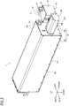
- the laser marker 1 of the present embodiment includes a first housing 20, a second housing 30 and the like.
- the first housing 20 is constituted by a rear first housing 20A and a front first housing 20B.
- the rear first housing 20A, the front first housing 20B, and the second housing 30 each have a substantially cuboid shape.
- the rear first housing 20A has the laser unit 10 and the like housed therein, and has a rear main body 22A and a rear cover 24A.
- the laser unit 10 and the like are attached to the rear main body 22A, and the rear cover 24A is fixed to the rear main body by a plurality of screws 26A. Thereby, the laser unit 10 is accommodated in the first housing 20.
- the front first housing 20B is attached to the rear main body 22A of the rear first housing 20A from a front direction-side.
- the front first housing 20B has the dichroic mirror 12, the reflecting mirror 14, the visible semiconductor laser 19 and the like housed therein, and has a front main body 22B and a front cover 24B.
- the dichroic mirror 12, the reflecting mirror 14, the visible semiconductor laser 19 and the like are attached to the front main body 22B, and the front cover 24B is fixed to the front main body by a plurality of screws 26B. Thereby, the dichroic mirror 12, the reflecting mirror 14, and the visible semiconductor laser 19 are accommodated in the first housing 20.
- the second housing 30 has the galvano scanner 16 and the like housed therein, and has a main body 32 and a cover 34.
- the galvano scanner 16 and the like are attached to the main body 32 (refer to FIGS. 6 and 10 which will be described later), and the cover 34 is fixed to the main body by a plurality of screws 36.
- the galvano scanner 16 is accommodated in the second housing 30.
- the f ⁇ lens 18 is fitted to the main body 32 of the second housing 30 (refer to FIGS. 4 and 6 which will be described later).
- the galvano scanner 16 can two-dimensionally scan the laser light Q and the visible laser light R reflected on each of the scanning mirrors 16X and 16Y via the f ⁇ lens 18 at an outside of the laser marker 1 of the present embodiment.
- a cable C of the galvano scanner 16 is bridged between the second housing 30 and the rear first housing 20A.
- the cable C is taken in the second housing 30 and the rear first housing 20A via cable grounds 200.
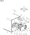
- FIGS. 3 and 4 are perspective views depicting a front part of the laser marker 1 of the present embodiment, in which the front cover 24B is removed from the front main body 22B.
- the laser marker 1 of the present embodiment can change a direction of the second housing 30 to a direction shown in FIG. 3 or a direction shown in FIG. 4 .
- the second housing 30 is provided so as to be rotatable with respect to the front first housing 20B by a connecting member 60 shown in FIG. 5 and the like, which will be described later. Note that, the connecting member 60 will be described in detail later.
- a case where the direction of the second housing 30 is the direction shown in FIG. 3 is referred to as "(the rotation position of) the second housing 30 is in a first rotation position.” In this case, the f ⁇ lens 18 faces downward.
- a case where the direction of the second housing 30 is the direction shown in FIG. 4 is referred to as "(the rotation position of) the second housing 30 is in a second rotation position.” In this case, the f ⁇ lens 18 faces forward.
- the laser marker 1 of the present embodiment can rotate the second housing 30 with respect to the first housing 20 within a range from 0 degree to 90 degrees.
- the rotation position of the second housing 30 can be fixed to the first rotation position shown in FIG. 3 or the second rotation position shown in FIG. 4 by a lock mechanism L shown in FIG. 6 and the like, which will be described later.
- the lock mechanism L has a pin 50, an attaching plate 52 and the like provided to the front main body 22B of the front first housing 20B, and they will be described in detail later.
- a transmission window 11 is provided over the front main body 22B and the rear main body 22A.
- the laser light Q emitted from the laser unit 10 passes through the transmission window 11 from the rear first housing 20A toward the front first housing 20B.
- the front main body 22B of the front first housing 20B is provided with a holder 13, a circular plate 40, a first sensor S1, a second sensor S2, the reflecting mirror 14 and the like.
- the holder 13 is attached to the front main body 22B.
- the visible semiconductor laser 19 is attached with being incorporated to a substrate (not shown) to the holder 13.
- the dichroic mirror 12 and the like are also attached to the holder 13.
- the first sensor S1 and the second sensor S2 are attached to a front wall surface of the holder13.
- the first sensor S1 and the second sensor S2 are microswitches.
- the circular plate 40 has an opening formed at a center thereof, and is configured to rotate together with the second housing 30. The details thereof will be described later.
- the circular plate 40 is formed with a protrusion 42 protruding toward the rear first housing 20A, in a predetermined area of an outer periphery.
- the protrusion 42 is formed with a detected portion 44 protruding toward the rear first housing 20A.
- the detected portion 44 is pressed against an actuator unit of the first sensor S1 in a case where the rotation position of the second housing 30 is in the first rotation position.
- the first sensor S1 detects that the rotation position of the second housing 30 is in the first rotation position.
- the detected portion 44 is pressed against an actuator unit of the second sensor S2 in a case where the rotation position of the second housing 30 is in the second rotation position.
- the second sensor S2 detects that the rotation position of the second housing 30 is in the second rotation position.
- any type of a sensor can be used as long as it can detect that the rotation position of the second housing 30 is in the first rotation position.
- any type of a sensor can be used as long as it can detect that the rotation position of the second housing 30 is in the second rotation position.
- the reflecting mirror 14 is attached in an opposite position to an opening portion of the circular plate 40 in the front and back direction and in the upper and lower direction of the front main body 22B of the front first housing 20B. Note that, the reflecting mirror 14 is omitted in FIGS. 3 and 4 . The same also applies to FIGS. 5 , 7 , 9 and 11 , which will be described later.
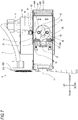
- FIGS. 5 to 8 depict a front part of the laser marker 1 of the present embodiment in the case where the rotation position of the second housing 30 is in the first rotation position.
- the front cover 24B is removed from the front main body 22B.
- the connecting member 60 has a substantially circular cylinder shape whose end faces face in the right and left direction, and is arranged over the front first housing 20B and the second housing 30.
- a left end of the connecting member 60 is fixed to the main body 32 of the second housing 30 via an O-ring 62 (refer to FIG. 6 ) by a screw 74 (refer to FIG. 5 ).
- a right end of the connecting member 60 is attached with being inserted in the front main body 22B of the front first housing 20B via an X-ring 64 (refer to FIG. 6 ).
- the connecting member 60 enables the second housing 30 to be rotatable with respect to the front first housing 20B.
- a right end face of the connecting member 60 is arranged in the front first housing 20B.
- the circular plate 40 is fixed to the right end face of the connecting member 60 by a screw 46 (refer to FIG. 7 ). Thereby, the circular plate 40 is configured to rotate together with the second housing 30 via the connecting member 60.
- the protrusion 42 and the detected portion 44 protrude from an outer peripheral surface of the right end of the connecting member 60 away from a rotation center 68 (refer to FIG. 8 ) of the connecting member 60.
- an outer peripheral surface of the circular plate 40 and the protrusion 42 and the detected portion 44 protruding from the circular plate 40 further protrude to an outside of the connecting member 60 than an outer peripheral surface of the right end of the connecting member 60.
- the connecting member 60 does not come off from the front first housing 20B.
- the protrusion 42 and the detected portion 44 may also protrude from the outer peripheral surface of the connecting member 60 away from the rotation center 68 of the connecting member 60, in the vicinity of the right end of the connecting member 60.
- the circular plate 40, the protrusion 42, and the detected portion 44 are inscribed in the front first housing 20B.
- the left end of the connecting member 60 protrudes outward from the circular cylinder part of the connecting member 60, and is fixed with being sandwiched between the front main body 22B of the front first housing 20B and the main body 32 of the second housing 30. Thereby, the second housing 30 can rotate with respect to the front first housing 20B without being displaced in the right and left direction.
- the connecting member 60 has a hollow structure 66 whose void is penetrated on both end faces thereof.
- the left void of the hollow structure 66 communicates with a through-hole 38 provided to the main body 32 of the second housing 30.
- the right void of the hollow structure 66 communicates with the opening portion of the circular plate 40 in the front first housing 20B.
- the hollow structure 66 is not limited to the tubular structure as along as it is a structure where the laser light Q and the visible laser light R pass from the front first housing 20B toward the second housing 30. Therefore, for example, the hollow structure 66 may have a structure where the void is exposed on side surfaces of the connecting member 60. In this case, however, the place where the void of the hollow structure 66 is exposed is shielded by the front main body 22B of the front first housing 20B or the main body 32 of the second housing 30.
- the lock mechanism L has a housing-side hole portion 29, a first hole portion 70, a second hole portion 72 and the like, in addition to the pin 50 and the attaching plate 52.
- the pin 50 has a collar portion 54 protruding outward from an outer peripheral surface of a shaft thereof.
- a tip end 56 of the pin 50 has a tapered shape.
- the shaft of the pin 50 is formed with a male screw 50A between the collar portion 54 and the tapered tip end 56.
- the housing-side hole portion 29 penetrates up to a hole, in which the right end of the connecting member 60 is inserted, of the front main body 22B of the front first housing 20B, and has a stepped shape in the upper and lower direction.
- An inner diameter of the housing-side hole portion 29 is smaller on a lower end-side than an upper and-side.
- an inner peripheral surface of the lower end-side of the housing-side hole portion 29 is formed with a female screw 29A that is engaged with the male screw 50A of the pin 50.
- the attaching plate 52 is attached with being convexly bent on the upper surface of the front main body 22B of the front first housing 20B.
- the pin 50 is inserted in the housing-side hole portion 29 with penetrating the attaching plate 52.
- the collar portion 54 of the pin 50 is arranged between the upper end-side of the housing-side hole portion 29 and the attaching plate 52.
- a coil spring 80 in which the shaft of the pin 50 is inserted is arranged between the collar portion 54 of the pin 50 and the stepped surface of the housing-side hole portion 29.
- An upper end of the coil spring 80 is stopped by the collar portion 54 of the pin 50, and a lower end of the coil spring 80 is stopped by the stepped surface of the housing-side hole portion 29.
- the pin 50 is urged upward.
- the collar portion 54 is butted against the attaching plate 52.
- the pin 50 is prevented from coming off from the attaching plate 52.
- the first hole portion 70 and the second hole portion 72 are provided to the connecting member 60.
- the first hole portion 70 and the second hole portion 72 are each formed such that an inner diameter thereof gradually decreases inward, thereby enabling guiding and fitting of the tip end 56 of the tapered pin 50. Therefore, the inner diameters of the first hole portion 70 and the second hole portion 72 are preferably formed to gradually decrease inward in a predetermined depth area where at least the first hole portion 70 and the second hole portion 72 can guide and fit the tip end 56 of the pin 50.
- the first hole portion 70 and the second hole portion 72 are each formed from the outer peripheral surface of the connecting member 60 toward the rotation center 68 of the connecting member 60, as seen in a direction (right and left direction) in which the right end of the connecting member 60 is inserted in the front first housing 20B.
- a direction (upper and lower direction, in FIG. 8 ) from the first hole portion 70 toward the rotation center 68 of the connecting member 60 and a direction (right and left direction, in FIG. 8 ) from the second hole portion 72 toward the rotation center 68 of the connecting member 60 intersect at 90 degrees.
- a direction from the actuator unit of the first sensor S1 toward the rotation center 68 of the second housing 30 and a direction from the actuator unit of the second sensor S2 toward the rotation center 68 of the second housing 30 intersect at 90 degrees.
- the housing-side hole portion 29 of the front first housing 20B and the first hole portion 70 of the connecting member 60 communicate with each other.
- the tip end 56 of the pin 50 protrudes downward from the housing-side hole portion 29 and is fitted in the first hole portion 70.
- the second housing 30 is fixed in the first rotation position.
- the male screw 50A of the pin 50 separates from the female screw 29A of the housing-side hole portion 29 and the tip end 56 of the pin 50 comes off from the first hole portion 70.
- the pin 50 is moved upward by the urging force of the coil spring 80 and is thus separated from the connecting member 60, and the tip end 56 of the pin 50 is moved to a position in which the pin comes off from the first hole portion 70. Thereby, the fixed state of the second housing 30 in the first rotation position is released.
- the front main body 22B of the front first housing 20B is provided therein with a first wall surface part 27 on a further upward side than the circular plate 40 and a second wall surface part 28 on a further downward side than the circular plate 40.
- the circular plate 40 is formed with a first end face part 42A and a second end face part 42B of the protrusion 42 by a step between an outer peripheral surface of the circular plate 40 and an outer peripheral surface of the protrusion 42.
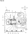
- FIGS. 9 to 12 depict a front part of the laser marker 1 of the present embodiment in a state when the rotation position of the second housing 30 is in the second rotation position.
- the front cover 24B is removed from the front main body 22B.
- FIGS. 9 to 12 correspond to FIGS. 5 to 8 where the rotation position of the second housing 30 is in the first rotation position. For this reason, in the following descriptions, the matters that are common to the state where the rotation position of the second housing 30 is in the first rotation position are omitted.
- the rotation position of the second housing 30 is in the second rotation position.
- the male screw 50A of the pin 50 separates from the female screw 29A of the housing-side hole portion 29 and the tip end 56 of the pin 50 comes off from the first hole portion 70.
- the pin 50 is moved upward by the urging force of the coil spring 80 and is thus separated from the connecting member 60, and the tip end 56 of the pin 50 is moved to a position in which the pin comes off from the second hole portion 72. Thereby, the fixed state of the second housing 30 in the second rotation position is released.
- the first wall surface part 27 and the second wall surface part 28 provided to the front main body 22B of the front first housing 20B are butted against the first end face part 42A or the second end face part 42B of the protrusion 42 as the connecting member 60 is rotated together with the second housing 30, thereby limiting the rotating range of the second housing 30 between the first rotation position and the second rotation position.
- the first hole portion 70 of the connecting member 60 corresponds to the first rotation position
- the second hole portion 72 of the connecting member 60 corresponds to the second rotation position.
- the lock mechanism L fixes the rotation of the connecting member 60 in the front first housing 20B, thereby fixing the second housing 30 to the first rotation position or the second rotation position.
- the laser marker 1 of the present embodiment is constituted by a print information preparation unit 2 and a laser processing unit 3.
- the print information preparation unit 2 includes an input operation unit 101, a control unit 103, a CD-R/W 113, a liquid crystal monitor (LCD) 115, and the like.
- the control unit 103 is connected to the input operation unit 101, the CD-R/W 113, the liquid crystal monitor 115 and the like via an input/output interface which is not shown.
- the input operation unit 101 is constituted by a mouse, a keyboard and the like (not shown), and is used in a case where a user designates any one of the first rotation position and the second rotation position, as the rotation position of the second housing 30, for example.
- the CD-R/W 113 is configured to read out or to write various data, application software and the like from or to a CD-ROM 117.
- the control unit 103 is configured to control the entire print information preparation unit 2, and includes a CPU 105, a RAM 107, a ROM 109, a hard disk drive (hereinbelow, referred to as "HDD") 111, and the like.
- the CPU 105 is an arithmetic device and a control device configured to control the entire print information preparation unit 2.
- the CPU 105, the RAM 107, and the ROM 109 are connected to each other via bus lines (not shown), and are configured to mutually transmit and receive data.
- the CPU 105 and HDD 111 are also connected to each other via an input/output interface (not shown), and are configured to mutually transmit and receive data.
- the RAM 107 is configured to temporarily store a variety of calculation results and the like calculated by the CPU 105.
- the ROM 109 is configured to store diverse programs and the like. In the HDD 111, programs of diverse application software, diverse data files, and the like are stored.
- the laser processing unit 3 includes a controller 201, a galvano driver 213, a semiconductor laser driver 215, the first sensor S1, the second sensor S2, a power supply unit for 24V DC/DC (24VDCDC) 217, and the like.
- the controller 201 is configured to control the entire laser processing unit 3.
- the controller 201 is electrically connected to the galvano driver 213, the semiconductor laser driver 215, the first sensor S1, the second sensor S2, the power supply unit for 24V DC/DC 217, and the like.
- the controller 201 is connected to the print information preparation unit 2 such that interactive communication can be performed, and is configured to receive each information (for example, print information, control parameters on the laser processing unit 3, a variety of instruction information from the user, and the like) transmitted from the print information preparation unit 2.
- the diverse instruction information from the user includes designation information indicating a result that the user designates, as the rotation position of the second housing 30, the first rotation position or the second rotation position.
- the controller 201 includes a CPU 203, a RAM 205, a ROM 207, an FPGA (Field-Programmable Gate Array) 211, and the like.
- the CPU 203 is an arithmetic device and a control device configured to control the entire laser processing unit 3.
- the CPU 203, the RAM 205, the ROM 207, and the FPGA 211 are mutually connected by bus lines (not shown) to mutually transmit and receive data.
- the RAM 205 is to temporarily store a variety of calculation results calculated by the CPU 203, XY coordinate data of a print pattern, and the like.
- the ROM 207 is configured to store a variety of programs, and for example, stores a program configured to calculate XY coordinate data of a print pattern, based on print information transmitted from the print information preparation unit 2, and to store the same in the RAM 205.
- the diverse programs include, for example, a program configured to store, in the RAM 205, a variety of control parameters indicative of a thickness, a depth and a number of a print pattern corresponding to print information input from the print information preparation unit 2, a speed of scanning the laser light Q by the galvano scanner 16, and the like, in addition to the above program.
- data such as a start point, an end point, a focus, a curvature and the like of a font of each of linear and elliptical characters is stored for each type of fonts.
- the CPU 203 is configured to perform diverse calculations and controls, based on the diverse programs stored in the ROM 207.
- the CPU 203 is configured to calculate XY coordinate data of a print pattern and galvano scanning speed information indicative of a speed of scanning the laser light Q by the galvano scanner 16, based on the print information input from the print information preparation unit 2.
- the CPU 203 is also configured to calculate drive angles, rotating speeds and the like of the galvano X-axis motor 17X and the galvano Y-axis motor 17Y, based on the diverse information (for example, the XY coordinate data of the print pattern, the galvano scanning speed information, and the like) and to output motor drive information indicative of the drive angles and rotating speeds to the galvano driver 213.
- the galvano driver 213 is configured to drive control the galvano X-axis motor 17X and the galvano Y-axis motor 17Y, based on the motor drive information input from the controller 201, to scan two dimensionally the laser light Q and the visible laser light R.
- the CPU 203 is configured to output an on-signal or an off-signal for instructing lighting or lights-out of the visible semiconductor laser 19 to the semiconductor laser driver 215.
- the semiconductor laser driver 215 is configured to turn on or turn off the visible semiconductor laser 19, based on the on-signal or the off-signal input from the controller 201.
- the FPGA211 is embedded in the controller 201, and is electrically connected to the galvano driver 213, the semiconductor laser driver 215, the first sensor S1, the second sensor S2, the power supply unit for 24V DC/DC 217, and the like.
- the power supply unit for 24V DC/DC 217 is electrically connected to a safety relay unit (hereinbelow, referred to as "SRU") 219 having a manual reset motor. Thereby, the SRU 219 can receive power from the power supply unit for 24V DC/DC 217.
- the SRU 219 is electrically connected to a DC power relay (DCPR) 221.
- the DC power relay 221 is wired between the laser supplying power source 223 and the laser unit 10.
- the laser supplying power source 223 is to supply power to the laser unit 10.
- the SRU 219 opens a contact point of the DC power relay 221. For this reason, the power cannot be supplied to the laser unit 10 by the laser supplying power source 223. At this time, in a case where a manual reset mode of the SRU 219 is set, the SRU 219 does not perform self-recovery.
- the SRU 219 executes manual reset and closes the contact point of the DC power relay 221. For this reason, the power can be supplied to the laser unit 10 by the laser supplying power source 223.
- the constitutional elements of the laser processing unit 3 are accommodated in the first housing 20 or the second housing 30.
- the galvano driver 213 is accommodated in the rear first housing 20A, and the galvano X-axis motor 17X and the galvano Y-axis motor 17Y are accommodated in the second housing 30.
- the galvano driver 213 and each of the motors 17X and 17Y are electrically connected to each other by the cable C.
- a logic indicated by a truth table 225 of FIG. 14 is incorporated in the FPGA211.
- “1" indicates that the contact point of the first sensor S1 is closed.
- the contact point of the first sensor S1 is closed in a case where the detected portion 44 is pressed against the actuator unit of the first sensor S1.
- the first sensor S1 outputs, as a detection signal, an on-signal indicating that the rotation position of the second housing 30 is in the first rotation position.
- the output on-signal is input to the FPGA 211.
- "0" indicates that the contact point of the first sensor S1 is opened.
- the contact point of the first sensor S1 is opened in a case where the detected portion 44 separates from the actuator unit of the first sensor S1.
- the on-signal is not output from the first sensor S1, and an off-signal indicating that the rotation position of the second housing 30 is not in the first rotation position is output as a detection signal.
- the output off-signal is input to the FPGA 211.
- a “second sensor” column of the truth table 225 “1" indicates that the contact point of the second sensor S2 is closed.
- the contact point of the second sensor S2 is closed in a case where the detected portion 44 is pressed against the actuator unit of the second sensor S2.
- the second sensor S2 outputs, as a detection signal, an on-signal indicating that the rotation position of the second housing 30 is in the second rotation position.
- the output on-signal is input to the FPGA 211.
- "0" indicates that the contact point of the second sensor S2 is opened.
- the contact point of the second sensor S2 is opened in a case where the detected portion 44 separates from the actuator unit of the second sensor S2.
- the on-signal is not output from the second sensor S2, and an off-signal indicating that the rotation position of the second housing 30 is not in the second rotation position is output as a detection signal.
- the output off-signal is input to the FPGA 211.
- “ON” indicates that the power supply unit for 24V DC/DC 217 becomes on. That is, in this case, the FPGA 211 outputs a signal for turning on the power supply unit for 24V DC/DC 217. The output signal is input to the power supply unit for 24V DC/DC 217. Thereby, the power supply unit for 24V DC/DC 217 becomes on, so that power can be supplied to the laser unit 10.
- “ON” indicates that the power supply unit for 24V DC/DC 217 becomes on. That is, in this case, the FPGA 211 outputs a signal for turning on the power supply unit for 24V DC/DC 217. The output signal is input to the power supply unit for 24V DC/DC 217. Thereby, the power supply unit for 24V DC/DC 217 becomes on, so that power can be supplied to the laser unit 10.
- the output of the FPGA 211 is performed, on condition that the rotation position of the second housing 30 detected by both the sensors S1 and S2 matches the rotation position of the second housing 30 designated from the input operation unit 101 by the user.
- the FPGA 211 when the signal for turning on the power supply unit 217 for 24V DC/DC is output, i.e., when the "first sensor” and “second sensor” columns in the truth table 225 is a combination of “1” and “0", in a case where the "first sensor” and “second sensor” columns is a combination of "0” and “1", the FPGA 211 outputs a signal to allow drive control of the galvano X-axis motor 17X and the galvano Y-axis motor 17Y to the galvano driver 213, and also outputs a signal to allow lighting of the visible semiconductor laser 19 to the semiconductor laser driver 215.
- each of the motors 17X and 17Y of the galvano scanner 16 can be drive-controlled, and the visible semiconductor laser 19 can be turned on.
- OFF is denoted in the "24VDCDC” column corresponding to this case.
- “OFF” indicates that the power supply unit for 24V DC/DC 217 becomes off. That is, in this case, the FPGA 211 outputs a signal for turning off the power supply unit for 24V DC/DC 217. The output signal is input to the power supply unit for 24V DC/DC 217. Thereby, the power supply unit for 24V DC/DC 217 becomes off, so that power cannot be supplied to the laser unit 10.
- NA is denoted in the "24VDCDC” column corresponding to this case. As described above, “NA” indicates that the detection signals of both the sensors S1 and S2 are not valid. However, in this case, the FPGA 211 outputs a signal to turn off the power supply unit for 24V DC/DC 217, in a similar manner to the above “OFF” case. The output signal is input to the power supply unit for 24V DC/DC 217. Thereby, the power supply unit for 24V DC/DC 217 becomes off, so that the power cannot be supplied to the laser unit 10.
- the FPGA 211 outputs a signal to stop drive control on the galvano X-axis motor 17X and the galvano Y-axis motor 17Y to the galvano driver 213, and also outputs an off-signal signal to instruct lights-out of the visible semiconductor laser 19 to the semiconductor laser driver 215.
- the drive control on each of the motors 17X and 17Y of the galvano scanner 16 is stopped, and the visible semiconductor laser 19 is turned off. Note that, in this case, the power supplying to the galvano scanner 16 and the visible semiconductor laser 19 may also be cut off.
- An emission control of the laser marker 1 of the present embodiment is described.
- An emission control program shown with a flowchart of FIG. 15 is stored in the ROM 207 of the controller 201, and is executed by the CPU 203 of the controller 201. The program is also executed as the power supply of the laser marker 1 becomes on.
- designation information obtaining processing is first executed in step (hereinbelow, simply denoted as "S") 10.
- designation information input from the print information preparation unit 2 to the controller 201 is obtained, and a designation result is specified based on the designation information.
- the designation result is a result indicating that the user designates, as the rotation position of the second housing 30, any one of the first rotation position or the second rotation position via the input operation unit 101. Note that, processing of a next step is not executed until the user's designation result is specified.
- detection signal obtaining processing S12 is executed. In this processing, the detection result of the first sensor S1 and the detection result of the second sensor S2 are obtained. The detection results of both the sensors S1 and S2 are an on-signal or off-signal.
- sensor state determining processing S14 is executed. This determination is performed based on the detection signals of both the sensors S1 and S2.
- emission impossible processing S16 is executed.
- This processing is executed as the detection signals of both the sensors S1 and S2 are input to the FPGA 211.
- notification processing S18 is executed.
- information is input from the controller 201 to the print information preparation unit 2, so that a message, which indicates that the rotation position of the second housing 30 is located in a position other than the first rotation position and the second rotation position, is displayed on the liquid crystal monitor 115.
- the notification may also be performed by a sound of a speaker, light of a rotating lamp, or the like.
- the designation information obtaining processing S10 is again executed.
- determination processing S20 of determining whether the sensor state matches the designation information is executed. This processing is executed, based on the detection signals of both the sensors S1 and S2 obtained in S12 and the designation result specified in S10. That is, it is determined whether the rotation position of the second housing 30 specified by the detection signals of both the sensors S1 and S2 matches the rotation position of the second housing 30 (any one of the first rotation position or the second rotation position) designated from the input operation unit 101 by the user.
- the emission impossible processing S16 is executed.
- the laser marker 1 of the present embodiment even in a case where the rotation position of the second housing 30 is in the first rotation position or the second rotation position, in a case where the rotation position of the second housing 30 does not match the rotation position designated by the user, the power cannot be supplied to the laser unit 10, the drive control on each of the motors 17X and 17Y of the galvano scanner 16 is stopped, and the visible semiconductor laser 19 is turned off.
- detection signal obtaining processing S22 is executed. This processing is similar to the detection signal obtaining processing S12.
- determination processing S24 of determining whether the sensor state has been changed is executed. In this processing, it is determined whether the detection signals of both the sensors S1 and S2 obtained in the detection signal obtaining processing S22 match the detection signals of both the sensors S1 and S2 obtained in the detection signal obtaining processing S12.
- the laser marker 1 of the present embodiment even in a case where the rotation position of the second housing 30 is in the first rotation position or the second rotation position and the rotation position of the second housing 30 matches the rotation position designated by the user, in a case where the rotation position of the second housing 30 is changed, the power cannot be supplied to the laser unit 10, the drive control on each of the motors 17X and 17Y of the galvano scanner 16 is stopped, and the visible semiconductor laser 19 is turned off.
- the power can be supplied to the laser unit 10, so that the laser light Q can be emitted to the outside of the second housing 30.
- each of the motors 17X and 17Y of the galvano scanner 16 can be drive-controlled, and the visible semiconductor laser 19 can be turned on.
- the laser marker 1 of the present embodiment in a case where the detection signals indicating that the rotation position of the second housing 30 is in the first rotation position or the second rotation position are output from both the sensors S1 and S2 (S14;1, 0) (S14;0, 1), the laser light Q can be emitted to the outside of the second housing 30 (S26).
- the detection signals indicating that the rotation position of the second housing 30 is in the first rotation position or the second rotation position are not output from both the sensors S1 and S2 (S14;0, 0) (S14;1, 1)
- the laser light Q cannot be emitted to the outside of the second housing 30 (S16).
- the laser marker 1 of the present embodiment in a case where the second housing 30 in which the galvano scanner 16 configured to scan the laser light Q to the outside of the second housing 30 is accommodated is rotated and the rotation position of the second housing 30 is not in the first rotation position and the second rotation position, the laser light Q cannot be emitted to the outside of the second housing 30, so that it is possible to ensure safety.
- the laser marker 1 of the present embodiment in a case where the rotation position of the second housing 30 indicated by the designation information input via the input operation unit 101 matches the rotation position of the second housing 30 indicated by the detection signals output from both the sensors S1 and S2 (S20: YES), the laser light Q can be emitted to the outside of the second housing 30 (S26). In a case where the rotation position of the second housing 30 indicated by the designation information input via the input operation unit 101 is different from the rotation position of the second housing 30 indicated by the detection signals output from both the sensors S1 and S2 (S20: NO), the laser light Q cannot be emitted to the outside of the second housing 30 (S16). Thereby, the safety is ensured because the laser marker 1 of the present embodiment can prevent the laser light Q from being emitted from the second housing 30 in an unintended direction of the user.
- the laser marker 1 of the present embodiment in a case where the rotation position of the second housing 30 is changed from one rotation position to the other rotation position of the first rotation position and the second rotation position (S20: YES) (S24: YES), the laser light Q cannot be emitted to the outside of the second housing 30 (S16). However, in a case where the designation information in which the other rotation position is designated as the rotation position of the second housing 30 is input by the input operation unit 101 (S20: YES) (S24: NO), the laser light Q can be emitted to the outside of the second housing 30 (S26).
- the laser light Q is prevented from being emitted from the second housing 30 in an unintended direction of the user, so that the laser marker 1 of the present embodiment is safe.
- the laser marker 1 of the present embodiment in the case where it is detected only by one of the first sensor S1 and the second sensor S2 that the rotation position of the second housing 30 is in the first rotation position or the second rotation position (S14;1, 0) (S14;0, 1), the laser light Q can be emitted to the outside of the second housing 30 (S26). Also, in the case where it is not detected by both the first sensor S1 and the second sensor S2 that the rotation position of the second housing 30 is in the first rotation position or the second rotation position (S14;0, 0), the laser light Q cannot be emitted to the outside of the second housing 30 (S16). Therefore, the laser marker 1 of the present embodiment is safe.
- the laser marker 1 of the present embodiment in the case where it is detected by both the first sensor S1 and the second sensor S2 that the rotation position of the second housing 30 is in the first rotation position and the second rotation position (S14;1, 1), the laser light Q cannot be emitted to the outside of the second housing 30 (S16). Therefore, the laser marker 1 of the present embodiment is safe.
- the laser marker 1 of the present embodiment in a case where the first sensor S1 and the second sensor S2 are seen in the direction (right and left direction) in which the front first housing 20B and the second housing 30 are aligned side by side, the direction from the actuator unit of the first sensor S1 toward the rotation center 68 of the second housing 30 and the direction from the actuator unit of the second sensor S2 toward the rotation center 68 of the second housing 30 are orthogonal to each other.
- the laser marker 1 of the present embodiment is configured such that the emission direction of the laser light Q in the case where the second housing 30 is in the first rotation position and the emission direction of the laser light Q in the case where the second housing 30 is in the second rotation position are orthogonal to each other.
- the laser marker 1 of the present embodiment in the case where the detection signals, which indicate that the rotation position of the second housing 30 is the first rotation position or the second rotation position, are output from both the sensors S1 and S2 (S14;1, 0) (S14;0, 1), the power can be supplied to the laser unit 10 (S26). Also, in a case where the detection signals, which indicate that the rotation position of the second housing 30 is the first rotation position or the second rotation position, are not output from both the sensors S1 and S2 (S14;0, 0) (S14;1, 1), the power cannot be supplied to the laser unit 10 (S16). Therefore, the laser marker 1 of the present embodiment is safe.
- the detection signals which indicate that the rotation position of the second housing 30 is the first rotation position or the second rotation position
- the detection signals are not output from both the sensors S1 and S2 (S14;0, 0) (S14;1, 1)
- the drive control on each of the motors 17X and 17Y of the galvano scanner 16 is stopped (S16).
- the drive control on each of the motors 17X and 17Y of the galvano scanner 16 is stopped during the rotation of the second housing 30, so that oscillation of the laser light Q by the galvano scanner 16 is prevented.
- the laser marker 1 of the present embodiment in a case where the detection signals, which indicate that the rotation position of the second housing 30 is the first rotation position or the second rotation position, are not output from both the sensors S1 and S2 (S14;0, 0) (S14;1, 1), the message indicating that the rotation position of the second housing 30 is in a position other than the first rotation position and the second rotation position is displayed on the liquid crystal monitor 115 (S18). Therefore, the laser marker 1 of the present embodiment is safe.
- the laser marker 1 of the present embodiment in a case where the detection signals, which indicate that the rotation position of the second housing 30 is the first rotation position or the second rotation position, are not output from both the sensors S1 and S2 (S14;0, 0) (S14;1, 1), the visible semiconductor laser 19 is turned off and the visible laser light R cannot be thus emitted to the outside of the second housing 30 (S16). Therefore, the laser marker 1 of the present embodiment is safe.
- the left end of the connecting member 60 is fixed to the main body 32 of the second housing 30, the right end of the connecting member 60 is attached with being inserted in the front main body 22B of the front first housing 20B, and the connecting member 60 connects the front first housing 20B and the second housing 30 each other, so that the second housing 30 can be rotated.
- the detected portion 44 protrudes from the outer peripheral surface of the right end of the connecting member 60 away from the rotation center 68 of the connecting member 60, and is pressed against the actuator units of both the sensors S1 and S2 in a case where the rotation position of the second housing 30 is the first rotation position or the second rotation position.
- both the sensors S1 and S2 can be easily arranged in the front main body 22B of the front first housing 20B, and it is possible to accurately detect that the rotation position of the second housing 30 is in the first rotation position or the second rotation position.
- the laser unit 10 is an example of the "laser light source”.
- the galvano scanner 16 is an example of the "scanning unit”.
- the visible semiconductor laser 19 is an example of the "guide light source”.
- the connecting member 60 is an example of the "connecting part".
- the left end of the connecting member 60 is an example of "one end of the connecting part”.
- the right end of the connecting member 60 is an example of the "other end of the connecting part”.
- the rotation center 68 of the connecting member 60 is an example of the "rotation center of the connecting part”.
- the input operation unit 101 is an example of the "user interface”.
- the liquid crystal monitor 115 is an example of the "notification device".
- the visible laser light R is an example of the "visible light”.
- the first sensor S1 and the second sensor S2 are examples of the "sensor".
- the outside of the second housing 30 is an example of the "outside”.
- the right and left direction is an example of the "direction in which the first housing and the second housing are aligned side by side.
- the direction from the actuator unit of the first sensor S1 toward the rotation center 68 of the second housing 30 is an example of the "first direction”.
- the direction from the actuator unit of the second sensor S2 toward the rotation center 68 of the second housing 30 is an example of the "second direction”.
- the present disclosure is not limited to the present embodiment, and can be diversely changed without departing from the gist thereof.
- the laser marker 1 of the present embodiment may be constituted by the print information preparation unit 2 and the laser processing unit 3, or may be constituted only by the laser processing unit 3.
- the right end of the connecting member 60 may be fixed to the front main body 22B of the front first housing 20B, and the left end of the connecting member 60 may be rotatably inserted in the main body 32 of the second housing 30.
- the lock mechanism L fixes the rotation of the connecting member 60 in the second housing 30, thereby fixing the second housing 30 in the first rotation position or the second rotation position.
- the connecting member 60 may also protrude from the main body 32 of the second housing 30 or the front main body 22B of the front first housing 20B.
- the second housing 30 may also be provided on a forward side of the front first housing 20B.
- the second housing 30 is arranged on a light path of the laser light Q and the visible laser light R traversing the inside of the front first housing 20B. For this reason, the reflecting mirror 14 is not required.
- the coil spring 80 may also be arranged between the attaching plate 52 and the collar portion 54 of the pin 50.
- the pin 50 is urged (downward) from the housing-side hole portion 29 toward the connecting part 90 by the coil spring 80. For this reason, in the case where the rotation position of the second housing 30 is not in the first rotation position and the second rotation position, the pin 50 is in contact with the outer peripheral surface of the connecting member 60.
- the lock mechanism L may be constituted by providing one of the first housing 20 and the second housing 30 with a pin and providing the other with a hole portion through which the pin passes.
- the lock mechanism L may be constituted by providing both the first housing 20 and the second housing 30 with hole portions and enabling a pin to pass therethrough.
- the lock mechanism L may also be constituted by a clamp tightening and fixing the first housing 20 and the second housing 30.
- the lock mechanism L may be constituted by providing one housing of the first housing 20 and the second housing 30 with a claw portion and the other housing with a groove portion to which the claw portion is engaged.
- the claw portion is engaged to the groove portion in the case where the rotation position of the second housing 30 is in the first rotation position or the second rotation position by the rotation of the second housing 30, and separates from the groove portion in the case where the rotation position of the second housing 30 is between the first rotation position and the second rotation position.
- the claw portion or groove portion may also be provided to the connecting member 60.
- the tip end 56 of the pin 50 may not be tapered.
- the first hole portion 70 and the second hole portion 72 are formed such that the inner diameters thereof gradually decrease toward the inner sides, like the present embodiment. Thereby, the pin 50 is guided to the first hole portion 70 and the second hole portion 72.
- the first hole portion 70 and the second hole portion 72 may not be formed such that the inner diameters thereof gradually decrease toward the inner sides.
- the tip end 56 of the pin 50 is tapered, like the present embodiment, such that the pin 50 is guided to the first hole portion 70 and the second hole portion 72.
- the rotation position of the second housing 30 may also be indicated by a high signal and a low signal or may also be indicated by information, unlike the present embodiment where the rotation position is indicated by binary signals of the on-signal and the off-signal.
- the emission control of the laser marker 1 of the present embodiment may be executed only by the FGPA211 or only by the CPU 203.
- the emission impossible processing S16 may also be executed by moving a shield plate onto the light path of the laser light Q or the visible laser light R while keeping the state where the laser unit 10 emits the laser light Q or the state where the visible semiconductor laser 19 emits the visible laser light R.
- the emission possible processing S26 is executed by moving the shield plate from the light path of the laser light Q or the visible laser light R.
Landscapes
- Physics & Mathematics (AREA)
- Optics & Photonics (AREA)
- Engineering & Computer Science (AREA)
- Mechanical Engineering (AREA)
- Plasma & Fusion (AREA)
- General Physics & Mathematics (AREA)
- Theoretical Computer Science (AREA)
- Laser Beam Processing (AREA)
- Laser Beam Printer (AREA)
Abstract
Description
- The present disclosure relates to a laser marker.
- In the related art, suggested are a variety of technologies relating to a laser marker configured to emit laser light. For example, the technology disclosed in
PTL 1 relates to a printing system having a bearing for enabling a printing beam exit member to rotate with respect to a housing. - PTL 1:
JP-A-2003-531010 - According to the technology disclosed in the
PTL 1, in a case where the printing beam exit member rotates via the bearing while a printing beam is emitted outward from the printing beam exit member, the printing beam may be emitted in an unexpected direction, which is dangerous. - The present disclosure has been made in view of the above situations, and is to provide a laser marker that ensures safety by making it impossible for laser light to be emitted outward when a second housing in which a scanning unit configured to scan the laser light outward is accommodated is rotated and is not in a predetermined position.
- The present specification discloses a laser marker including a laser light source configured to emit laser light, a scanning unit configured to scan the laser light outward, a first housing accommodating the laser light source, a second housing connected to the first housing and accommodating the scanning unit, the second housing being rotatable with respect to the first housing, and a sensor configured to output a detection signal indicative of a rotation position of the second housing, wherein in a case a detection signal indicating that the rotation position of the second housing is a first rotation position or a second rotation position is output from the sensor, it becomes possible for the laser light to be emitted outward, and in a case the detection signal indicating that the rotation position of the second housing is the first rotation position or the second rotation position is not output from the sensor, it becomes impossible for the laser light to be emitted outward.
- According to the present disclosure, the laser marker ensures safety by making it impossible for the laser light to be emitted outward when the second housing in which the scanning unit configured to scan the laser light outward is accommodated is rotated and is not in a predetermined position.
-
- [
FIG. 1] FIG. 1 depicts a schematic configuration of a laser marker of the present embodiment. - [
FIG. 2] FIG. 2 is a perspective view depicting the laser marker. - [
FIG. 3] FIG. 3 is a perspective view depicting a part of the laser marker when a second housing is in a state where it is fixed in a first rotation position. - [
FIG. 4] FIG. 4 is a perspective view depicting a part of the laser marker in a case where the second housing is in a state where it is fixed in a second rotation position. - [
FIG. 5] FIG. 5 is a plan view depicting a part of the laser marker. - [
FIG. 6] FIG. 6 is a sectional view of the laser marker taken along a line X1-X1 ofFIG. 5 . - [
FIG. 7] FIG. 7 is a sectional view of the laser marker taken along a line Y1-Y1 ofFIG. 5 . - [
FIG. 8] FIG. 8 is a sectional view of the laser marker taken along a line Y2-Y2 ofFIG. 5 . - [
FIG. 9] FIG. 9 is a plan view depicting a part of the laser marker shown inFIG. 4 . - [
FIG. 10] FIG. 10 is a sectional view of the laser marker taken along a line X1-X1 ofFIG. 9 . - [
FIG. 11] FIG. 11 is a sectional view of the laser marker taken along a line Y1-Y1 ofFIG. 9 . - [
FIG. 12] FIG. 12 is a sectional view of the laser marker taken along a line Y2-Y2 ofFIG. 9 . - [
FIG. 13] FIG. 13 is a block diagram depicting an electrical configuration of the laser marker. - [
FIG. 14] FIG. 14 depicts a truth table of the laser marker. - [
FIG. 15] FIG. 15 is a flowchart depicting electrical operations of the laser marker. - [
FIG. 16] FIG. 16 depicts a modified example of the laser marker. - Hereinbelow, the laser marker of the present disclosure will be described with reference to the drawings, based on embodiments. In
FIGS. 1 to 12 and16 used for descriptions below, some of the basic configuration are omitted, and the dimensional ratios of the shown parts are not always accurate. Note that, in descriptions below, the upper and lower direction, the front and back direction, and the right and left direction are as shown inFIGS. 2 to 12 and16 . - As shown in
FIG. 1 , alaser marker 1 of the present embodiment includes alaser unit 10, adichroic mirror 12, a reflectingmirror 14, agalvano scanner 16, anfθ lens 18, avisible semiconductor laser 19, and the like. - The
laser unit 10 has alaser oscillator 10A, a beam expander 10B, and the like. Thelaser oscillator 10A is constituted by CO2 laser, YAG laser and the like, and is configured to emit laser light Q. A light diameter of the laser light Q is adjusted (for example, expanded) by thebeam expander 10B. - The
visible semiconductor laser 19 is configured to emit visible laser light R, for example, red laser light, which is visible interfering light. The visible laser light R is used so as to project a print pattern image, which is to be marked (printed) by the laser light Q, to a processing target W, for example. Note that, a wavelength of the visible laser light R is different from a wavelength of the laser light Q. In the present embodiment, for example, the wavelength of the laser light Q is 1064nm, and the wavelength of the visible laser light R is 650nm. - In the
dichroic mirror 12, almost all of the incident laser light Q is penetrated. In thedichroic mirror 12, the visible laser light R is incident at an incident angle of 45 degrees and is reflected onto a light path of the laser light Q at a reflection angle of 45 degrees, in a substantially central position in which the laser light Q is penetrated. The reflectance of thedichroic mirror 12 depends on wavelengths. Specifically, thedichroic mirror 12 is surface-treated with a multi-layered structure of a dielectric layer and a metal layer, has high reflectance for the wavelength of the visible laser light R, and is configured to cause most (99%) of light of other wavelengths to be penetrated therethrough. - Note that, the dotted line in
FIG. 1 indicates an optical axis of the visible laser light R. In contrast, the dashed-dotted line inFIG. 1 indicates an optical axis of the laser light Q. In addition, among the dashed-dotted lines inFIG. 1 , the dashed-dotted line between thedichroic mirror 12 and the processing target W also indicates the optical axis of the visible laser light R. - The laser light Q penetrating the
dichroic mirror 12 and the visible laser light R reflected on thedichroic mirror 12 are reflected on the reflectingmirror 14 toward thegalvano scanner 16. - The
galvano scanner 16 is to two-dimensionally scan the laser light Q and the visible laser light R reflected on the reflectingmirror 14. In thegalvano scanner 16, agalvano X-axis motor 17X and a galvano Y-axis motor 17Y shown inFIG. 13 , which will be described later, are arranged such that motor shafts thereof are orthogonal to each other, and scanningmirrors galvano scanner 16, in a case where each of themotors scanning mirrors - The
fθ lens 18 is to focus the laser light Q and the visible laser light R two-dimensionally scanned by thegalvano scanner 16 onto the processing target W. Therefore, the laser light Q and the visible laser light R are two dimensionally scanned on the processing target W under drive control on each of themotors - As shown in
FIG. 2 , thelaser marker 1 of the present embodiment includes afirst housing 20, asecond housing 30 and the like. Thefirst housing 20 is constituted by a rearfirst housing 20A and a frontfirst housing 20B. The rearfirst housing 20A, the frontfirst housing 20B, and thesecond housing 30 each have a substantially cuboid shape. - The rear
first housing 20A has thelaser unit 10 and the like housed therein, and has a rearmain body 22A and arear cover 24A. Thelaser unit 10 and the like are attached to the rearmain body 22A, and therear cover 24A is fixed to the rear main body by a plurality ofscrews 26A. Thereby, thelaser unit 10 is accommodated in thefirst housing 20. - The front
first housing 20B is attached to the rearmain body 22A of the rearfirst housing 20A from a front direction-side. The frontfirst housing 20B has thedichroic mirror 12, the reflectingmirror 14, thevisible semiconductor laser 19 and the like housed therein, and has a frontmain body 22B and afront cover 24B. Thedichroic mirror 12, the reflectingmirror 14, thevisible semiconductor laser 19 and the like are attached to the frontmain body 22B, and thefront cover 24B is fixed to the front main body by a plurality ofscrews 26B. Thereby, thedichroic mirror 12, the reflectingmirror 14, and thevisible semiconductor laser 19 are accommodated in thefirst housing 20. - The
second housing 30 has thegalvano scanner 16 and the like housed therein, and has amain body 32 and acover 34. Thegalvano scanner 16 and the like are attached to the main body 32 (refer toFIGS. 6 and10 which will be described later), and thecover 34 is fixed to the main body by a plurality ofscrews 36. Thereby, thegalvano scanner 16 is accommodated in thesecond housing 30. In addition, thefθ lens 18 is fitted to themain body 32 of the second housing 30 (refer toFIGS. 4 and6 which will be described later). Thereby, thegalvano scanner 16 can two-dimensionally scan the laser light Q and the visible laser light R reflected on each of the scanning mirrors 16X and 16Y via thefθ lens 18 at an outside of thelaser marker 1 of the present embodiment. - A cable C of the
galvano scanner 16 is bridged between thesecond housing 30 and the rearfirst housing 20A. The cable C is taken in thesecond housing 30 and the rearfirst housing 20A viacable grounds 200. -
FIGS. 3 and4 are perspective views depicting a front part of thelaser marker 1 of the present embodiment, in which thefront cover 24B is removed from the frontmain body 22B. Thelaser marker 1 of the present embodiment can change a direction of thesecond housing 30 to a direction shown inFIG. 3 or a direction shown inFIG. 4 . For this reason, thesecond housing 30 is provided so as to be rotatable with respect to the frontfirst housing 20B by a connectingmember 60 shown inFIG. 5 and the like, which will be described later. Note that, the connectingmember 60 will be described in detail later. - In the present embodiment, a case where the direction of the
second housing 30 is the direction shown inFIG. 3 is referred to as "(the rotation position of) thesecond housing 30 is in a first rotation position." In this case, thefθ lens 18 faces downward. In contrast, a case where the direction of thesecond housing 30 is the direction shown inFIG. 4 is referred to as "(the rotation position of) thesecond housing 30 is in a second rotation position." In this case, thefθ lens 18 faces forward. Thelaser marker 1 of the present embodiment can rotate thesecond housing 30 with respect to thefirst housing 20 within a range from 0 degree to 90 degrees. - In the
laser marker 1 of the present embodiment, the rotation position of thesecond housing 30 can be fixed to the first rotation position shown inFIG. 3 or the second rotation position shown inFIG. 4 by a lock mechanism L shown inFIG. 6 and the like, which will be described later. Note that, the lock mechanism L has apin 50, an attachingplate 52 and the like provided to the frontmain body 22B of the frontfirst housing 20B, and they will be described in detail later. - At a place where the front
first housing 20B is attached to the rearfirst housing 20A, atransmission window 11 is provided over the frontmain body 22B and the rearmain body 22A. The laser light Q emitted from thelaser unit 10 passes through thetransmission window 11 from the rearfirst housing 20A toward the frontfirst housing 20B. - The front
main body 22B of the frontfirst housing 20B is provided with aholder 13, acircular plate 40, a first sensor S1, a second sensor S2, the reflectingmirror 14 and the like. Theholder 13 is attached to the frontmain body 22B. Thevisible semiconductor laser 19 is attached with being incorporated to a substrate (not shown) to theholder 13. Thedichroic mirror 12 and the like are also attached to theholder 13. The first sensor S1 and the second sensor S2 are attached to a front wall surface of the holder13. The first sensor S1 and the second sensor S2 are microswitches. - The
circular plate 40 has an opening formed at a center thereof, and is configured to rotate together with thesecond housing 30. The details thereof will be described later. Thecircular plate 40 is formed with aprotrusion 42 protruding toward the rearfirst housing 20A, in a predetermined area of an outer periphery. Theprotrusion 42 is formed with a detectedportion 44 protruding toward the rearfirst housing 20A. - As shown in
FIG. 3 , the detectedportion 44 is pressed against an actuator unit of the first sensor S1 in a case where the rotation position of thesecond housing 30 is in the first rotation position. Thereby, the first sensor S1 detects that the rotation position of thesecond housing 30 is in the first rotation position. In contrast, as shown inFIG. 4 , the detectedportion 44 is pressed against an actuator unit of the second sensor S2 in a case where the rotation position of thesecond housing 30 is in the second rotation position. Thereby, the second sensor S2 detects that the rotation position of thesecond housing 30 is in the second rotation position. - Note that, for the first sensor S1, any type of a sensor can be used as long as it can detect that the rotation position of the
second housing 30 is in the first rotation position. Similarly, for the second sensor S2, any type of a sensor can be used as long as it can detect that the rotation position of thesecond housing 30 is in the second rotation position. - The reflecting
mirror 14 is attached in an opposite position to an opening portion of thecircular plate 40 in the front and back direction and in the upper and lower direction of the frontmain body 22B of the frontfirst housing 20B. Note that, the reflectingmirror 14 is omitted inFIGS. 3 and4 . The same also applies toFIGS. 5 ,7 ,9 and11 , which will be described later. -
FIGS. 5 to 8 depict a front part of thelaser marker 1 of the present embodiment in the case where the rotation position of thesecond housing 30 is in the first rotation position. InFIGS. 5 to 7 , thefront cover 24B is removed from the frontmain body 22B. - As shown in
FIGS. 5 to 7 , the connectingmember 60 has a substantially circular cylinder shape whose end faces face in the right and left direction, and is arranged over the frontfirst housing 20B and thesecond housing 30. A left end of the connectingmember 60 is fixed to themain body 32 of thesecond housing 30 via an O-ring 62 (refer toFIG. 6 ) by a screw 74 (refer toFIG. 5 ). In contrast, a right end of the connectingmember 60 is attached with being inserted in the frontmain body 22B of the frontfirst housing 20B via an X-ring 64 (refer toFIG. 6 ). Thereby, the connectingmember 60 enables thesecond housing 30 to be rotatable with respect to the frontfirst housing 20B. A right end face of the connectingmember 60 is arranged in the frontfirst housing 20B. - The
circular plate 40 is fixed to the right end face of the connectingmember 60 by a screw 46 (refer toFIG. 7 ). Thereby, thecircular plate 40 is configured to rotate together with thesecond housing 30 via the connectingmember 60. Theprotrusion 42 and the detectedportion 44 protrude from an outer peripheral surface of the right end of the connectingmember 60 away from a rotation center 68 (refer toFIG. 8 ) of the connectingmember 60. In the frontfirst housing 20B, an outer peripheral surface of thecircular plate 40 and theprotrusion 42 and the detectedportion 44 protruding from thecircular plate 40 further protrude to an outside of the connectingmember 60 than an outer peripheral surface of the right end of the connectingmember 60. Thereby, in the case where thesecond housing 30 is rotated with respect to the frontfirst housing 20B, the connectingmember 60 does not come off from the frontfirst housing 20B. Note that, theprotrusion 42 and the detectedportion 44 may also protrude from the outer peripheral surface of the connectingmember 60 away from therotation center 68 of the connectingmember 60, in the vicinity of the right end of the connectingmember 60. - In addition, the
circular plate 40, theprotrusion 42, and the detectedportion 44 are inscribed in the frontfirst housing 20B. The left end of the connectingmember 60 protrudes outward from the circular cylinder part of the connectingmember 60, and is fixed with being sandwiched between the frontmain body 22B of the frontfirst housing 20B and themain body 32 of thesecond housing 30. Thereby, thesecond housing 30 can rotate with respect to the frontfirst housing 20B without being displaced in the right and left direction. - As shown in
FIGS. 6 and7 , the connectingmember 60 has ahollow structure 66 whose void is penetrated on both end faces thereof. The left void of thehollow structure 66 communicates with a through-hole 38 provided to themain body 32 of thesecond housing 30. In contrast, the right void of thehollow structure 66 communicates with the opening portion of thecircular plate 40 in the frontfirst housing 20B. Thereby, the laser light Q and the visible laser light R pass through thehollow structure 66 of the connectingmember 60 after they are reflected on the reflectingmirror 14 in the front first housing 20Bto be incident on thegalvano scanner 16 in thesecond housing 30. - However, the
hollow structure 66 is not limited to the tubular structure as along as it is a structure where the laser light Q and the visible laser light R pass from the frontfirst housing 20B toward thesecond housing 30. Therefore, for example, thehollow structure 66 may have a structure where the void is exposed on side surfaces of the connectingmember 60. In this case, however, the place where the void of thehollow structure 66 is exposed is shielded by the frontmain body 22B of the frontfirst housing 20B or themain body 32 of thesecond housing 30. - As shown in
FIG. 8 , the lock mechanism L has a housing-side hole portion 29, afirst hole portion 70, asecond hole portion 72 and the like, in addition to thepin 50 and the attachingplate 52. Thepin 50 has acollar portion 54 protruding outward from an outer peripheral surface of a shaft thereof. Atip end 56 of thepin 50 has a tapered shape. The shaft of thepin 50 is formed with amale screw 50A between thecollar portion 54 and the taperedtip end 56. - The housing-
side hole portion 29 penetrates up to a hole, in which the right end of the connectingmember 60 is inserted, of the frontmain body 22B of the frontfirst housing 20B, and has a stepped shape in the upper and lower direction. An inner diameter of the housing-side hole portion 29 is smaller on a lower end-side than an upper and-side. In addition, an inner peripheral surface of the lower end-side of the housing-side hole portion 29 is formed with afemale screw 29A that is engaged with themale screw 50A of thepin 50. - The attaching
plate 52 is attached with being convexly bent on the upper surface of the frontmain body 22B of the frontfirst housing 20B. Thepin 50 is inserted in the housing-side hole portion 29 with penetrating the attachingplate 52. Thereby, thecollar portion 54 of thepin 50 is arranged between the upper end-side of the housing-side hole portion 29 and the attachingplate 52. In addition, acoil spring 80 in which the shaft of thepin 50 is inserted is arranged between thecollar portion 54 of thepin 50 and the stepped surface of the housing-side hole portion 29. An upper end of thecoil spring 80 is stopped by thecollar portion 54 of thepin 50, and a lower end of thecoil spring 80 is stopped by the stepped surface of the housing-side hole portion 29. For this reason, thepin 50 is urged upward. However, in a case where thepin 50 is moved upward, thecollar portion 54 is butted against the attachingplate 52. Thereby, thepin 50 is prevented from coming off from the attachingplate 52. - The
first hole portion 70 and thesecond hole portion 72 are provided to the connectingmember 60. Thefirst hole portion 70 and thesecond hole portion 72 are each formed such that an inner diameter thereof gradually decreases inward, thereby enabling guiding and fitting of thetip end 56 of the taperedpin 50. Therefore, the inner diameters of thefirst hole portion 70 and thesecond hole portion 72 are preferably formed to gradually decrease inward in a predetermined depth area where at least thefirst hole portion 70 and thesecond hole portion 72 can guide and fit thetip end 56 of thepin 50. - The
first hole portion 70 and thesecond hole portion 72 are each formed from the outer peripheral surface of the connectingmember 60 toward therotation center 68 of the connectingmember 60, as seen in a direction (right and left direction) in which the right end of the connectingmember 60 is inserted in the frontfirst housing 20B. In addition, a direction (upper and lower direction, inFIG. 8 ) from thefirst hole portion 70 toward therotation center 68 of the connectingmember 60 and a direction (right and left direction, inFIG. 8 ) from thesecond hole portion 72 toward therotation center 68 of the connectingmember 60 intersect at 90 degrees. - Note that, in a case where the first sensor S1 and the second sensor S2 are seen in a direction (right and left direction) in which the front
first housing 20B and thesecond housing 30 are arranged, a direction from the actuator unit of the first sensor S1 toward therotation center 68 of thesecond housing 30 and a direction from the actuator unit of the second sensor S2 toward therotation center 68 of thesecond housing 30 intersect at 90 degrees. - In the case where the rotation position of the
second housing 30 is in the first rotation position, the housing-side hole portion 29 of the frontfirst housing 20B and thefirst hole portion 70 of the connectingmember 60 communicate with each other. In this case, when thepin 50 is pushed downward against the urging force of thecoil spring 80 and is turned in a predetermined direction, thetip end 56 of thepin 50 protrudes downward from the housing-side hole portion 29 and is fitted in thefirst hole portion 70. Thereby, thesecond housing 30 is fixed in the first rotation position. At this time, though thepin 50 is urged upward by thecoil spring 80, themale screw 50A of thepin 50 and thefemale screw 29A of the housing-side hole portion 29 are fitted with each other, so that thetip end 56 of thepin 50 is prevented from coming off from thefirst hole portion 70. - In contrast, in a case where the
pin 50 is turned in an opposite direction to the predetermined direction, themale screw 50A of thepin 50 separates from thefemale screw 29A of the housing-side hole portion 29 and thetip end 56 of thepin 50 comes off from thefirst hole portion 70. At this time, thepin 50 is moved upward by the urging force of thecoil spring 80 and is thus separated from the connectingmember 60, and thetip end 56 of thepin 50 is moved to a position in which the pin comes off from thefirst hole portion 70. Thereby, the fixed state of thesecond housing 30 in the first rotation position is released. - As shown in
FIG. 7 , the frontmain body 22B of the frontfirst housing 20B is provided therein with a firstwall surface part 27 on a further upward side than thecircular plate 40 and a secondwall surface part 28 on a further downward side than thecircular plate 40. In contrast, thecircular plate 40 is formed with a firstend face part 42A and a secondend face part 42B of theprotrusion 42 by a step between an outer peripheral surface of thecircular plate 40 and an outer peripheral surface of theprotrusion 42. - For this reason, in a case where the
circular plate 40 fixed to the right end face of the connectingmember 60 is rotated together with thesecond housing 30, the firstend face part 42A of thecircular plate 40 is butted against the firstwall surface part 27 of the frontfirst housing 20B or the secondend face part 42B of thecircular plate 40 is butted against the secondwall surface part 28 of the frontfirst housing 20B. Thereby, a rotating range of thesecond housing 30 is limited. InFIG. 7 , the firstend face part 42A of thecircular plate 40 is butted against the firstwall surface part 27 of the frontfirst housing 20B. In such a state, the rotation position of thesecond housing 30 is in the first rotation position. -
FIGS. 9 to 12 depict a front part of thelaser marker 1 of the present embodiment in a state when the rotation position of thesecond housing 30 is in the second rotation position. InFIGS. 9 to 11 , thefront cover 24B is removed from the frontmain body 22B. Note that,FIGS. 9 to 12 correspond toFIGS. 5 to 8 where the rotation position of thesecond housing 30 is in the first rotation position. For this reason, in the following descriptions, the matters that are common to the state where the rotation position of thesecond housing 30 is in the first rotation position are omitted. - As shown in
FIG. 11 , in a case where the secondend face part 42B of thecircular plate 40 is butted against the secondwall surface part 28 of the frontfirst housing 20B, the rotation position of thesecond housing 30 is in the second rotation position. - In the state where the rotation position of the
second housing 30 is in the second rotation position, as shown inFIG. 12 , the housing-side hole portion 29 of the frontfirst housing 20B and thesecond hole portion 72 of the connectingmember 60 communicate with each other. In this case, when thepin 50 is pushed downward against the urging force of thecoil spring 80 and is turned in a predetermined direction, thetip end 56 of thepin 50 protrudes downward from the housing-side hole portion 29 and is fitted in thesecond hole portion 72. Thereby, thesecond housing 30 is fixed in the second rotation position. At this time, though thepin 50 is urged upward by thecoil spring 80, themale screw 50A of thepin 50 and thefemale screw 29A of the housing-side hole portion 29 are fitted with each other, so that thetip end 56 of thepin 50 is prevented from coming off from thefirst hole portion 70. - In contrast, in a case where the
pin 50 is turned in an opposite direction to the predetermined direction, themale screw 50A of thepin 50 separates from thefemale screw 29A of the housing-side hole portion 29 and thetip end 56 of thepin 50 comes off from thefirst hole portion 70. At this time, thepin 50 is moved upward by the urging force of thecoil spring 80 and is thus separated from the connectingmember 60, and thetip end 56 of thepin 50 is moved to a position in which the pin comes off from thesecond hole portion 72. Thereby, the fixed state of thesecond housing 30 in the second rotation position is released. - By the above configuration, the first
wall surface part 27 and the secondwall surface part 28 provided to the frontmain body 22B of the frontfirst housing 20B are butted against the firstend face part 42A or the secondend face part 42B of theprotrusion 42 as the connectingmember 60 is rotated together with thesecond housing 30, thereby limiting the rotating range of thesecond housing 30 between the first rotation position and the second rotation position. In addition, thefirst hole portion 70 of the connectingmember 60 corresponds to the first rotation position, and thesecond hole portion 72 of the connectingmember 60 corresponds to the second rotation position. - In this way, the lock mechanism L fixes the rotation of the connecting
member 60 in the frontfirst housing 20B, thereby fixing thesecond housing 30 to the first rotation position or the second rotation position. - Subsequently, an electrical configuration of the
laser marker 1 of the present embodiment is described. As shown inFIG. 13 , thelaser marker 1 of the present embodiment is constituted by a printinformation preparation unit 2 and alaser processing unit 3. First, an electrical configuration of the printinformation preparation unit 2 is described. The printinformation preparation unit 2 includes aninput operation unit 101, acontrol unit 103, a CD-R/W 113, a liquid crystal monitor (LCD) 115, and the like. Thecontrol unit 103 is connected to theinput operation unit 101, the CD-R/W 113, theliquid crystal monitor 115 and the like via an input/output interface which is not shown. - The
input operation unit 101 is constituted by a mouse, a keyboard and the like (not shown), and is used in a case where a user designates any one of the first rotation position and the second rotation position, as the rotation position of thesecond housing 30, for example. - The CD-R/
W 113 is configured to read out or to write various data, application software and the like from or to a CD-ROM 117. - The
control unit 103 is configured to control the entire printinformation preparation unit 2, and includes aCPU 105, aRAM 107, aROM 109, a hard disk drive (hereinbelow, referred to as "HDD") 111, and the like. TheCPU 105 is an arithmetic device and a control device configured to control the entire printinformation preparation unit 2. TheCPU 105, theRAM 107, and theROM 109 are connected to each other via bus lines (not shown), and are configured to mutually transmit and receive data. TheCPU 105 andHDD 111 are also connected to each other via an input/output interface (not shown), and are configured to mutually transmit and receive data. - The
RAM 107 is configured to temporarily store a variety of calculation results and the like calculated by theCPU 105. TheROM 109 is configured to store diverse programs and the like. In theHDD 111, programs of diverse application software, diverse data files, and the like are stored. - Subsequently, an electrical configuration of the
laser processing unit 3 is described. Thelaser processing unit 3 includes acontroller 201, agalvano driver 213, asemiconductor laser driver 215, the first sensor S1, the second sensor S2, a power supply unit for 24V DC/DC (24VDCDC) 217, and the like. - The
controller 201 is configured to control the entirelaser processing unit 3. Thecontroller 201 is electrically connected to thegalvano driver 213, thesemiconductor laser driver 215, the first sensor S1, the second sensor S2, the power supply unit for 24V DC/DC 217, and the like. Thecontroller 201 is connected to the printinformation preparation unit 2 such that interactive communication can be performed, and is configured to receive each information (for example, print information, control parameters on thelaser processing unit 3, a variety of instruction information from the user, and the like) transmitted from the printinformation preparation unit 2. - Note that, the diverse instruction information from the user includes designation information indicating a result that the user designates, as the rotation position of the
second housing 30, the first rotation position or the second rotation position. - The
controller 201 includes aCPU 203, aRAM 205, aROM 207, an FPGA (Field-Programmable Gate Array) 211, and the like. TheCPU 203 is an arithmetic device and a control device configured to control the entirelaser processing unit 3. TheCPU 203, theRAM 205, theROM 207, and theFPGA 211 are mutually connected by bus lines (not shown) to mutually transmit and receive data. TheRAM 205 is to temporarily store a variety of calculation results calculated by theCPU 203, XY coordinate data of a print pattern, and the like. - The
ROM 207 is configured to store a variety of programs, and for example, stores a program configured to calculate XY coordinate data of a print pattern, based on print information transmitted from the printinformation preparation unit 2, and to store the same in theRAM 205. Note that, the diverse programs include, for example, a program configured to store, in theRAM 205, a variety of control parameters indicative of a thickness, a depth and a number of a print pattern corresponding to print information input from the printinformation preparation unit 2, a speed of scanning the laser light Q by thegalvano scanner 16, and the like, in addition to the above program. In theROM 207, data such as a start point, an end point, a focus, a curvature and the like of a font of each of linear and elliptical characters is stored for each type of fonts. - The
CPU 203 is configured to perform diverse calculations and controls, based on the diverse programs stored in theROM 207. - The
CPU 203 is configured to calculate XY coordinate data of a print pattern and galvano scanning speed information indicative of a speed of scanning the laser light Q by thegalvano scanner 16, based on the print information input from the printinformation preparation unit 2. TheCPU 203 is also configured to calculate drive angles, rotating speeds and the like of the galvanoX-axis motor 17X and the galvano Y-axis motor 17Y, based on the diverse information (for example, the XY coordinate data of the print pattern, the galvano scanning speed information, and the like) and to output motor drive information indicative of the drive angles and rotating speeds to thegalvano driver 213. - The
galvano driver 213 is configured to drive control the galvanoX-axis motor 17X and the galvano Y-axis motor 17Y, based on the motor drive information input from thecontroller 201, to scan two dimensionally the laser light Q and the visible laser light R. - The
CPU 203 is configured to output an on-signal or an off-signal for instructing lighting or lights-out of thevisible semiconductor laser 19 to thesemiconductor laser driver 215. Thesemiconductor laser driver 215 is configured to turn on or turn off thevisible semiconductor laser 19, based on the on-signal or the off-signal input from thecontroller 201. - The FPGA211 is embedded in the
controller 201, and is electrically connected to thegalvano driver 213, thesemiconductor laser driver 215, the first sensor S1, the second sensor S2, the power supply unit for 24V DC/DC 217, and the like. The power supply unit for 24V DC/DC 217 is electrically connected to a safety relay unit (hereinbelow, referred to as "SRU") 219 having a manual reset motor. Thereby, theSRU 219 can receive power from the power supply unit for 24V DC/DC 217. TheSRU 219 is electrically connected to a DC power relay (DCPR) 221. TheDC power relay 221 is wired between the laser supplyingpower source 223 and thelaser unit 10. The laser supplyingpower source 223 is to supply power to thelaser unit 10. - When the
FPGA 211 turns off the power supply unit for 24V DC/DC 217 to cut off power supplying to theSRU 219, theSRU 219 opens a contact point of theDC power relay 221. For this reason, the power cannot be supplied to thelaser unit 10 by the laser supplyingpower source 223. At this time, in a case where a manual reset mode of theSRU 219 is set, theSRU 219 does not perform self-recovery. - In contrast, in a case where the
FPGA 211 turns on the power supply unit for 24V DC/DC 217 to execute power supplying to theSRU 219, theSRU 219 executes manual reset and closes the contact point of theDC power relay 221. For this reason, the power can be supplied to thelaser unit 10 by the laser supplyingpower source 223. - The constitutional elements of the
laser processing unit 3 are accommodated in thefirst housing 20 or thesecond housing 30. Specifically, thegalvano driver 213 is accommodated in the rearfirst housing 20A, and the galvanoX-axis motor 17X and the galvano Y-axis motor 17Y are accommodated in thesecond housing 30. Note that, thegalvano driver 213 and each of themotors - A logic indicated by a truth table 225 of
FIG. 14 is incorporated in the FPGA211. - In a "first sensor" column of the truth table 225, "1" indicates that the contact point of the first sensor S1 is closed. The contact point of the first sensor S1 is closed in a case where the detected
portion 44 is pressed against the actuator unit of the first sensor S1. In this case, the first sensor S1 outputs, as a detection signal, an on-signal indicating that the rotation position of thesecond housing 30 is in the first rotation position. The output on-signal is input to theFPGA 211. In contrast, "0" indicates that the contact point of the first sensor S1 is opened. The contact point of the first sensor S1 is opened in a case where the detectedportion 44 separates from the actuator unit of the first sensor S1. In this case, the on-signal is not output from the first sensor S1, and an off-signal indicating that the rotation position of thesecond housing 30 is not in the first rotation position is output as a detection signal. The output off-signal is input to theFPGA 211. - In a "second sensor" column of the truth table 225, "1" indicates that the contact point of the second sensor S2 is closed. The contact point of the second sensor S2 is closed in a case where the detected
portion 44 is pressed against the actuator unit of the second sensor S2. In this case, the second sensor S2 outputs, as a detection signal, an on-signal indicating that the rotation position of thesecond housing 30 is in the second rotation position. The output on-signal is input to theFPGA 211. In contrast, "0" indicates that the contact point of the second sensor S2 is opened. The contact point of the second sensor S2 is opened in a case where the detectedportion 44 separates from the actuator unit of the second sensor S2. In this case, the on-signal is not output from the second sensor S2, and an off-signal indicating that the rotation position of thesecond housing 30 is not in the second rotation position is output as a detection signal. The output off-signal is input to theFPGA 211. - In a "sensor state" column of the truth table 225, "0 degree" indicates that it is detected by both the sensors S1 and S2 that the rotation position of the
second housing 30 is in the first rotation position. That is, in a combination where the "first sensor" and "second sensor" columns are "1" and "0", since the on-signal of the first sensor S1 and the off-signal of the second sensor S2 are input to theFPGA 211, it is detected by both the sensors S1 and S2 that the rotation position of thesecond housing 30 is in the first rotation position. For this reason, "0 degree" is denoted in the "sensor state" corresponding to this case. Also, "ON" is denoted in a "24VDCDC" column corresponding to this case. "ON" indicates that the power supply unit for 24V DC/DC 217 becomes on. That is, in this case, theFPGA 211 outputs a signal for turning on the power supply unit for 24V DC/DC 217. The output signal is input to the power supply unit for 24V DC/DC 217. Thereby, the power supply unit for 24V DC/DC 217 becomes on, so that power can be supplied to thelaser unit 10. - In the "sensor state" column of the truth table 225, "90 degrees" indicates that it is detected by both the sensors S1 and S2 that the rotation position of the
second housing 30 is in the second rotation position. That is, in a combination where the "first sensor" and "second sensor" columns are "0" and "1 ", since the off-signal of the first sensor S1 and the on-signal of the second sensor S2 are input to theFPGA 211, it is detected by both the sensors S1 and S2 that the rotation position of thesecond housing 30 is in the second rotation position. For this reason, "90 degrees" is denoted in the "sensor state" corresponding to this case. Also, "ON" is denoted in the "24VDCDC" column corresponding to this case. "ON" indicates that the power supply unit for 24V DC/DC 217 becomes on. That is, in this case, theFPGA 211 outputs a signal for turning on the power supply unit for 24V DC/DC 217. The output signal is input to the power supply unit for 24V DC/DC 217. Thereby, the power supply unit for 24V DC/DC 217 becomes on, so that power can be supplied to thelaser unit 10. - The output of the
FPGA 211 is performed, on condition that the rotation position of thesecond housing 30 detected by both the sensors S1 and S2 matches the rotation position of thesecond housing 30 designated from theinput operation unit 101 by the user. - Note that, when the signal for turning on the
power supply unit 217 for 24V DC/DC is output, i.e., when the "first sensor" and "second sensor" columns in the truth table 225 is a combination of "1" and "0", in a case where the "first sensor" and "second sensor" columns is a combination of "0" and "1", theFPGA 211 outputs a signal to allow drive control of the galvanoX-axis motor 17X and the galvano Y-axis motor 17Y to thegalvano driver 213, and also outputs a signal to allow lighting of thevisible semiconductor laser 19 to thesemiconductor laser driver 215. - That is, in a case where the rotation position of the
second housing 30 is in the first rotation position or the second rotation position, the power can be supplied to thelaser unit 10, each of themotors galvano scanner 16 can be drive-controlled, and thevisible semiconductor laser 19 can be turned on. - In contrast, in the "sensor state" column of the truth table 225, "under rotation" indicates that it is detected by both the sensors S1 and S2 that the rotation position of the
second housing 30 is between the first rotation position and the second rotation position. That is, in a combination where the "first sensor" and "second sensor" columns are "0" and "0", since the off-signal of the first sensor S1 and the off-signal of the second sensor S2 are input to theFPGA 211, it is detected by both the sensors S1 and S2 that the rotation position of thesecond housing 30 is between the first rotation position and the second rotation position. For this reason, "under rotation" is denoted in the "sensor state" column corresponding to this case. Also, "OFF" is denoted in the "24VDCDC" column corresponding to this case. "OFF" indicates that the power supply unit for 24V DC/DC 217 becomes off. That is, in this case, theFPGA 211 outputs a signal for turning off the power supply unit for 24V DC/DC 217. The output signal is input to the power supply unit for 24V DC/DC 217. Thereby, the power supply unit for 24V DC/DC 217 becomes off, so that power cannot be supplied to thelaser unit 10. - In the "sensor state" column of the truth table 225, "NA" indicates that the detection signals of both the sensors S1 and S2 are not valid. That is, in a combination where the "first sensor" and "second sensor" columns are "1" and "1", the on-signal of the first sensor S1 and the on-signal of the second sensor S2 are input to the FPGA211. However, since it is difficult for the detected
portion 44 to be pressed against each actuator unit of both the sensors S1 and S2 at the same time, it is assumed that the detection signals of both the sensors S1 and S2 are not valid. For this reason, "NA" is denoted in the "sensor state" column corresponding to this case. Also, "NA" is denoted in the "24VDCDC" column corresponding to this case. As described above, "NA" indicates that the detection signals of both the sensors S1 and S2 are not valid. However, in this case, theFPGA 211 outputs a signal to turn off the power supply unit for 24V DC/DC 217, in a similar manner to the above "OFF" case. The output signal is input to the power supply unit for 24V DC/DC 217. Thereby, the power supply unit for 24V DC/DC 217 becomes off, so that the power cannot be supplied to thelaser unit 10. - Note that, in a case where the signal for turning off the power supply unit for 24V DC/
DC 217 is output, i.e., in a case where the "first sensor" and "second sensor" columns in the truth table 225 is a combination of "0" and "0", in a case where the "first sensor" and "second sensor" columns is a combination of "1" and "1", theFPGA 211 outputs a signal to stop drive control on the galvanoX-axis motor 17X and the galvano Y-axis motor 17Y to thegalvano driver 213, and also outputs an off-signal signal to instruct lights-out of thevisible semiconductor laser 19 to thesemiconductor laser driver 215. - That is, in a case where the rotation position of the
second housing 30 is between the first rotation position and the second rotation position, or in a case where the detection signals of both the sensors S1 and S2 are not valid, the power cannot be supplied to thelaser unit 10, the drive control on each of themotors galvano scanner 16 is stopped, and thevisible semiconductor laser 19 is turned off. Note that, in this case, the power supplying to thegalvano scanner 16 and thevisible semiconductor laser 19 may also be cut off. - Subsequently, an emission control of the
laser marker 1 of the present embodiment is described. An emission control program shown with a flowchart ofFIG. 15 is stored in theROM 207 of thecontroller 201, and is executed by theCPU 203 of thecontroller 201. The program is also executed as the power supply of thelaser marker 1 becomes on. In the emission control program shown with the flowchart ofFIG. 15 , designation information obtaining processing is first executed in step (hereinbelow, simply denoted as "S") 10. - In this processing, designation information input from the print
information preparation unit 2 to thecontroller 201 is obtained, and a designation result is specified based on the designation information. The designation result is a result indicating that the user designates, as the rotation position of thesecond housing 30, any one of the first rotation position or the second rotation position via theinput operation unit 101. Note that, processing of a next step is not executed until the user's designation result is specified. - In a case where the user's designation result is specified, detection signal obtaining processing S12 is executed. In this processing, the detection result of the first sensor S1 and the detection result of the second sensor S2 are obtained. The detection results of both the sensors S1 and S2 are an on-signal or off-signal.
- In a case where the detection signals of both the sensors S1 and S2 are obtained, sensor state determining processing S14 is executed. This determination is performed based on the detection signals of both the sensors S1 and S2.
- In a case where the detection signals of both the sensors S1 and S2 are all the off-signals (S14;0, 0), or in a case where the detection signals of both the sensors S1 and S2 are all the on-signals (S14;1, 1), emission impossible processing S16 is executed. This processing is executed as the detection signals of both the sensors S1 and S2 are input to the
FPGA 211. Thereby, in thelaser marker 1 of the present embodiment, in a case where the rotation position of thesecond housing 30 is between the first rotation position and the second rotation position or in a case where the detection signals of both the sensors S1 and S2 are not valid, the power cannot be supplied to thelaser unit 10, so that the laser light Q cannot be emitted to the outside of thesecond housing 30. In addition, in thelaser marker 1 of the present embodiment, the drive control on each of themotors galvano scanner 16 is stopped and thevisible semiconductor laser 19 is turned off. - In a case where the emission impossible processing S16 is executed, notification processing S18 is executed. In this processing, information is input from the
controller 201 to the printinformation preparation unit 2, so that a message, which indicates that the rotation position of thesecond housing 30 is located in a position other than the first rotation position and the second rotation position, is displayed on theliquid crystal monitor 115. Thereby, it is notified to the user that the rotation position of thesecond housing 30 is located in a position other than the first rotation position and the second rotation position. Note that, the notification may also be performed by a sound of a speaker, light of a rotating lamp, or the like. Thereafter, the designation information obtaining processing S10 is again executed. - In contrast, in a case where the detection result of the first sensor S1 is the on-signal and the detection result of the second sensor S2 is the off-signal (S14;1, 0), or in a case where the detection result of the first sensor S1 is the off-signal and the detection result of the second sensor S2 is the on-signal (S14;0, 1), determination processing S20 of determining whether the sensor state matches the designation information is executed. This processing is executed, based on the detection signals of both the sensors S1 and S2 obtained in S12 and the designation result specified in S10. That is, it is determined whether the rotation position of the
second housing 30 specified by the detection signals of both the sensors S1 and S2 matches the rotation position of the second housing 30 (any one of the first rotation position or the second rotation position) designated from theinput operation unit 101 by the user. - In a case where it is determined that the sensor state does not match the designation information (S20: NO), i.e., the rotation position of the
second housing 30 specified by the detection signals of both the sensors S1 and S2 does not match the rotation position of thesecond housing 30 designated from theinput operation unit 101 by the user, the emission impossible processing S16 is executed. Thereby, in thelaser marker 1 of the present embodiment, even in a case where the rotation position of thesecond housing 30 is in the first rotation position or the second rotation position, in a case where the rotation position of thesecond housing 30 does not match the rotation position designated by the user, the power cannot be supplied to thelaser unit 10, the drive control on each of themotors galvano scanner 16 is stopped, and thevisible semiconductor laser 19 is turned off. - Note that, in this case, information is input from the
controller 201 to the printinformation preparation unit 2, so that a popup window for urging the user to designate the rotation position of thesecond housing 30 via theinput operation unit 101 is displayed on theliquid crystal monitor 115. - In contrast, in a case where it is determined that the sensor state matches the designation information (S20: YES), i.e., the rotation position of the
second housing 30 specified by the detection signals of both the sensors S1 and S2 matches the rotation position of thesecond housing 30 designated from theinput operation unit 101 by the user, detection signal obtaining processing S22 is executed. This processing is similar to the detection signal obtaining processing S12. - In a case where the detection signal obtaining processing S22 is executed, determination processing S24 of determining whether the sensor state has been changed is executed. In this processing, it is determined whether the detection signals of both the sensors S1 and S2 obtained in the detection signal obtaining processing S22 match the detection signals of both the sensors S1 and S2 obtained in the detection signal obtaining processing S12.
- In a case where the detection signals of both the sensors S1 and S2 obtained in both the detection signal obtaining processing S12 and S22 are not matched, the rotation position of the
second housing 30 is different at the time of both the detection signal obtaining processing S12 and S22. Therefore, it is determined that the sensor state has been changed (S24: YES). In this case, the emission impossible processing S16 is executed. Thereby, in thelaser marker 1 of the present embodiment, even in a case where the rotation position of thesecond housing 30 is in the first rotation position or the second rotation position and the rotation position of thesecond housing 30 matches the rotation position designated by the user, in a case where the rotation position of thesecond housing 30 is changed, the power cannot be supplied to thelaser unit 10, the drive control on each of themotors galvano scanner 16 is stopped, and thevisible semiconductor laser 19 is turned off. - In contrast, in a case where the detection signals of both the sensors S1 and S2 obtained in both the detection signal obtaining processing S12 and S22 are matched, the rotation position of the
second housing 30 is the same at the time of both the detection signal obtaining processing S12 and S22. Therefore, it is determined that the sensor state has not been changed (S24: NO). In this case, emission possible processing S26 is executed. This processing is executed as the detection signals of both the sensors S1 and S2 are input to theFPGA 211. Thereby, in thelaser marker 1 of the present embodiment, in a case where the rotation position of thesecond housing 30 is in the first rotation position or the second rotation position, the rotation position of thesecond housing 30 matches the rotation position designated by the user, and the rotation position of thesecond housing 30 is not changed, the power can be supplied to thelaser unit 10, so that the laser light Q can be emitted to the outside of thesecond housing 30. In addition, in thelaser marker 1 of the present embodiment, each of themotors galvano scanner 16 can be drive-controlled, and thevisible semiconductor laser 19 can be turned on. - As described in detail above, according to the
laser marker 1 of the present embodiment, in a case where the detection signals indicating that the rotation position of thesecond housing 30 is in the first rotation position or the second rotation position are output from both the sensors S1 and S2 (S14;1, 0) (S14;0, 1), the laser light Q can be emitted to the outside of the second housing 30 (S26). When the detection signals indicating that the rotation position of thesecond housing 30 is in the first rotation position or the second rotation position are not output from both the sensors S1 and S2 (S14;0, 0) (S14;1, 1), the laser light Q cannot be emitted to the outside of the second housing 30 (S16). Thereby, according to thelaser marker 1 of the present embodiment, in a case where thesecond housing 30 in which thegalvano scanner 16 configured to scan the laser light Q to the outside of thesecond housing 30 is accommodated is rotated and the rotation position of thesecond housing 30 is not in the first rotation position and the second rotation position, the laser light Q cannot be emitted to the outside of thesecond housing 30, so that it is possible to ensure safety. - In addition, according to the
laser marker 1 of the present embodiment, in a case where the rotation position of thesecond housing 30 indicated by the designation information input via theinput operation unit 101 matches the rotation position of thesecond housing 30 indicated by the detection signals output from both the sensors S1 and S2 (S20: YES), the laser light Q can be emitted to the outside of the second housing 30 (S26). In a case where the rotation position of thesecond housing 30 indicated by the designation information input via theinput operation unit 101 is different from the rotation position of thesecond housing 30 indicated by the detection signals output from both the sensors S1 and S2 (S20: NO), the laser light Q cannot be emitted to the outside of the second housing 30 (S16). Thereby, the safety is ensured because thelaser marker 1 of the present embodiment can prevent the laser light Q from being emitted from thesecond housing 30 in an unintended direction of the user. - Further, according to the
laser marker 1 of the present embodiment, in a case where the rotation position of thesecond housing 30 is changed from one rotation position to the other rotation position of the first rotation position and the second rotation position (S20: YES) (S24: YES), the laser light Q cannot be emitted to the outside of the second housing 30 (S16). However, in a case where the designation information in which the other rotation position is designated as the rotation position of thesecond housing 30 is input by the input operation unit 101 (S20: YES) (S24: NO), the laser light Q can be emitted to the outside of the second housing 30 (S26). Thereby, in a case where thesecond housing 30 is rotated from the first rotation position or the second rotation position, the user is urged to check the direction of the laser light Q to be emitted from thesecond housing 30 by an input operation on theinput operation unit 101. Therefore, the laser light Q is prevented from being emitted from thesecond housing 30 in an unintended direction of the user, so that thelaser marker 1 of the present embodiment is safe. - In addition, according to the
laser marker 1 of the present embodiment, in the case where it is detected only by one of the first sensor S1 and the second sensor S2 that the rotation position of thesecond housing 30 is in the first rotation position or the second rotation position (S14;1, 0) (S14;0, 1), the laser light Q can be emitted to the outside of the second housing 30 (S26). Also, in the case where it is not detected by both the first sensor S1 and the second sensor S2 that the rotation position of thesecond housing 30 is in the first rotation position or the second rotation position (S14;0, 0), the laser light Q cannot be emitted to the outside of the second housing 30 (S16). Therefore, thelaser marker 1 of the present embodiment is safe. - Further, according to the
laser marker 1 of the present embodiment, in the case where it is detected by both the first sensor S1 and the second sensor S2 that the rotation position of thesecond housing 30 is in the first rotation position and the second rotation position (S14;1, 1), the laser light Q cannot be emitted to the outside of the second housing 30 (S16). Therefore, thelaser marker 1 of the present embodiment is safe. - In addition, according to the
laser marker 1 of the present embodiment, in a case where the first sensor S1 and the second sensor S2 are seen in the direction (right and left direction) in which the frontfirst housing 20B and thesecond housing 30 are aligned side by side, the direction from the actuator unit of the first sensor S1 toward therotation center 68 of thesecond housing 30 and the direction from the actuator unit of the second sensor S2 toward therotation center 68 of thesecond housing 30 are orthogonal to each other. For this reason, thelaser marker 1 of the present embodiment is configured such that the emission direction of the laser light Q in the case where thesecond housing 30 is in the first rotation position and the emission direction of the laser light Q in the case where thesecond housing 30 is in the second rotation position are orthogonal to each other. - Further, according to the
laser marker 1 of the present embodiment, in the case where the detection signals, which indicate that the rotation position of thesecond housing 30 is the first rotation position or the second rotation position, are output from both the sensors S1 and S2 (S14;1, 0) (S14;0, 1), the power can be supplied to the laser unit 10 (S26). Also, in a case where the detection signals, which indicate that the rotation position of thesecond housing 30 is the first rotation position or the second rotation position, are not output from both the sensors S1 and S2 (S14;0, 0) (S14;1, 1), the power cannot be supplied to the laser unit 10 (S16). Therefore, thelaser marker 1 of the present embodiment is safe. - In addition, according to the
laser marker 1 of the present embodiment, in the case where the detection signals, which indicate that the rotation position of thesecond housing 30 is the first rotation position or the second rotation position, are not output from both the sensors S1 and S2 (S14;0, 0) (S14;1, 1), the drive control on each of themotors galvano scanner 16 is stopped (S16). Thereby, according to thelaser marker 1 of the present embodiment, even in a case where a noise occurs in the cable C of thegalvano scanner 16 due to the rotation of thesecond housing 30, the drive control on each of themotors galvano scanner 16 is stopped during the rotation of thesecond housing 30, so that oscillation of the laser light Q by thegalvano scanner 16 is prevented. - In addition, according to the
laser marker 1 of the present embodiment, in a case where the detection signals, which indicate that the rotation position of thesecond housing 30 is the first rotation position or the second rotation position, are not output from both the sensors S1 and S2 (S14;0, 0) (S14;1, 1), the message indicating that the rotation position of thesecond housing 30 is in a position other than the first rotation position and the second rotation position is displayed on the liquid crystal monitor 115 (S18). Therefore, thelaser marker 1 of the present embodiment is safe. - In addition, according to the
laser marker 1 of the present embodiment, in a case where the detection signals, which indicate that the rotation position of thesecond housing 30 is the first rotation position or the second rotation position, are not output from both the sensors S1 and S2 (S14;0, 0) (S14;1, 1), thevisible semiconductor laser 19 is turned off and the visible laser light R cannot be thus emitted to the outside of the second housing 30 (S16). Therefore, thelaser marker 1 of the present embodiment is safe. - Further, according to the
laser marker 1 of the present embodiment, the left end of the connectingmember 60 is fixed to themain body 32 of thesecond housing 30, the right end of the connectingmember 60 is attached with being inserted in the frontmain body 22B of the frontfirst housing 20B, and the connectingmember 60 connects the frontfirst housing 20B and thesecond housing 30 each other, so that thesecond housing 30 can be rotated. Also, the detectedportion 44 protrudes from the outer peripheral surface of the right end of the connectingmember 60 away from therotation center 68 of the connectingmember 60, and is pressed against the actuator units of both the sensors S1 and S2 in a case where the rotation position of thesecond housing 30 is the first rotation position or the second rotation position. For this reason, since the actuator units are distant from therotation center 68 of the connectingmember 60, both the sensors S1 and S2 can be easily arranged in the frontmain body 22B of the frontfirst housing 20B, and it is possible to accurately detect that the rotation position of thesecond housing 30 is in the first rotation position or the second rotation position. - Additionally describing, in the present embodiment, the
laser unit 10 is an example of the "laser light source". Thegalvano scanner 16 is an example of the "scanning unit". Thevisible semiconductor laser 19 is an example of the "guide light source". The connectingmember 60 is an example of the "connecting part". The left end of the connectingmember 60 is an example of "one end of the connecting part". The right end of the connectingmember 60 is an example of the "other end of the connecting part". Therotation center 68 of the connectingmember 60 is an example of the "rotation center of the connecting part". Theinput operation unit 101 is an example of the "user interface". Theliquid crystal monitor 115 is an example of the "notification device". The visible laser light R is an example of the "visible light". The first sensor S1 and the second sensor S2 are examples of the "sensor". The outside of thesecond housing 30 is an example of the "outside". The right and left direction is an example of the "direction in which the first housing and the second housing are aligned side by side. The direction from the actuator unit of the first sensor S1 toward therotation center 68 of thesecond housing 30 is an example of the "first direction". The direction from the actuator unit of the second sensor S2 toward therotation center 68 of thesecond housing 30 is an example of the "second direction". - Note that, the present disclosure is not limited to the present embodiment, and can be diversely changed without departing from the gist thereof. For example, as described above, the
laser marker 1 of the present embodiment may be constituted by the printinformation preparation unit 2 and thelaser processing unit 3, or may be constituted only by thelaser processing unit 3. - In addition, the right end of the connecting
member 60 may be fixed to the frontmain body 22B of the frontfirst housing 20B, and the left end of the connectingmember 60 may be rotatably inserted in themain body 32 of thesecond housing 30. In this case, however, the lock mechanism L fixes the rotation of the connectingmember 60 in thesecond housing 30, thereby fixing thesecond housing 30 in the first rotation position or the second rotation position. - The connecting
member 60 may also protrude from themain body 32 of thesecond housing 30 or the frontmain body 22B of the frontfirst housing 20B. - The
second housing 30 may also be provided on a forward side of the frontfirst housing 20B. In this case, thesecond housing 30 is arranged on a light path of the laser light Q and the visible laser light R traversing the inside of the frontfirst housing 20B. For this reason, the reflectingmirror 14 is not required. - As shown in
FIG. 16 , thecoil spring 80 may also be arranged between the attachingplate 52 and thecollar portion 54 of thepin 50. In this case, thepin 50 is urged (downward) from the housing-side hole portion 29 toward the connectingpart 90 by thecoil spring 80. For this reason, in the case where the rotation position of thesecond housing 30 is not in the first rotation position and the second rotation position, thepin 50 is in contact with the outer peripheral surface of the connectingmember 60. - The lock mechanism L may be constituted by providing one of the
first housing 20 and thesecond housing 30 with a pin and providing the other with a hole portion through which the pin passes. Alternatively, the lock mechanism L may be constituted by providing both thefirst housing 20 and thesecond housing 30 with hole portions and enabling a pin to pass therethrough. - The lock mechanism L may also be constituted by a clamp tightening and fixing the
first housing 20 and thesecond housing 30. - Alternatively, the lock mechanism L may be constituted by providing one housing of the
first housing 20 and thesecond housing 30 with a claw portion and the other housing with a groove portion to which the claw portion is engaged. In this case, the claw portion is engaged to the groove portion in the case where the rotation position of thesecond housing 30 is in the first rotation position or the second rotation position by the rotation of thesecond housing 30, and separates from the groove portion in the case where the rotation position of thesecond housing 30 is between the first rotation position and the second rotation position. Note that, the claw portion or groove portion may also be provided to the connectingmember 60. - The
tip end 56 of thepin 50 may not be tapered. In this case, thefirst hole portion 70 and thesecond hole portion 72 are formed such that the inner diameters thereof gradually decrease toward the inner sides, like the present embodiment. Thereby, thepin 50 is guided to thefirst hole portion 70 and thesecond hole portion 72. Thefirst hole portion 70 and thesecond hole portion 72 may not be formed such that the inner diameters thereof gradually decrease toward the inner sides. In this case, thetip end 56 of thepin 50 is tapered, like the present embodiment, such that thepin 50 is guided to thefirst hole portion 70 and thesecond hole portion 72. - The rotation position of the
second housing 30 may also be indicated by a high signal and a low signal or may also be indicated by information, unlike the present embodiment where the rotation position is indicated by binary signals of the on-signal and the off-signal. - The emission control of the
laser marker 1 of the present embodiment may be executed only by the FGPA211 or only by theCPU 203. - The emission impossible processing S16 may also be executed by moving a shield plate onto the light path of the laser light Q or the visible laser light R while keeping the state where the
laser unit 10 emits the laser light Q or the state where thevisible semiconductor laser 19 emits the visible laser light R. In this case, the emission possible processing S26 is executed by moving the shield plate from the light path of the laser light Q or the visible laser light R. - 1: laser marker, 10: laser unit, 16: galvano scanner, 19: visible semiconductor laser, 20: first housing, 30: second housing, 44: detected portion, 60: connecting member, 68: rotation center of connecting member, 101: input operation unit, 115: liquid crystal monitor, 203: CPU, 205: RAM, 207: ROM, 211: FPGA, Q: laser light, R: visible laser light, S1: first sensor, S2: second sensor, S16: emission impossible processing, S18: notification processing, S26: emission possible processing
Claims (11)
- A laser marker comprising:a laser light source configured to emit laser light;a scanning unit configured to scan the laser light outward;a first housing accommodating the laser light source;a second housing connected to the first housing and accommodating the scanning unit, the second housing being rotatable with respect to the first housing; anda sensor configured to output a detection signal indicative of a rotation position of the second housing,wherein in a case a detection signal indicating that the rotation position of the second housing is a first rotation position or a second rotation position is output from the sensor, it becomes possible for the laser light to be emitted outward, andwherein in a case the detection signal indicating that the rotation position of the second housing is the first rotation position or the second rotation position is not output from the sensor, it becomes impossible for the laser light to be emitted outward.
- The laser marker according to claim 1, further comprising:a user interface with which designation information is input, the designation information designating any one of the first rotation position or the second rotation position as the rotation position of the second housing,wherein in a case a rotation position of the second housing indicated by the designation information input by the user interface matches the rotation position of the second housing indicated by the detection signal output from the sensor, it becomes possible for the laser light to be emitted outward, andwherein in a case the rotation position of the second housing indicated by the designation information input by the user interface is different from the rotation position of the second housing indicated by the detection signal output from the sensor, it becomes impossible for the laser light to be emitted outward.
- The laser marker according to claim 2, wherein in a case the rotation position of the second housing is changed from one rotation position of the first rotation position and the second rotation position to the other rotation position, it becomes impossible for the laser light to be emitted outward until designation information of designating said the other rotation position as the rotation position of the second housing is input by the user interface.
- The laser marker according to any one of claims 1 to 3,wherein the sensor comprises:a first sensor configured to detect the rotation position of the second housing in a case the second housing is in the first rotation position; anda second sensor configured to detect the rotation position of the second housing in a case the second housing is in the second rotation position,wherein in a case only one of the first sensor and the second sensor detects the rotation position of the second housing, it becomes possible for the laser light to be emitted outward, andwherein in a case both the first sensor and the second sensor do not detect the rotation position of the second housing, it becomes impossible for the laser light to be emitted outward.
- The laser marker according to claim 4, wherein in a case both the first sensor and the second sensor detect the rotation position of the second housing, it becomes impossible for the laser light to be emitted outward.
- The laser marker according to claim 4 or 5, wherein a first direction from the first sensor toward a rotation center of the second housing and a second direction from the second sensor toward the rotation center of the second housing are orthogonal to each other, as seen in a direction in which the first housing and the second housing are aligned side by side.
- The laser marker according to any one of claims 1 to 6,wherein in a case the detection signal is output from the sensor, the detection signal indicating that the rotation position of the second housing is the first rotation position or the second rotation position, power supplying to the laser light source is executed, andwherein in a case the detection signal is not output from the sensor, the detection signal indicating that the rotation position of the second housing is the first rotation position or the second rotation position, power supplying to the laser light source is cut off.
- The laser marker according to any one of claims 1 to 7, wherein in a case the detection signal is not output from the sensor, the detection signal indicating that the rotation position of the second housing is the first rotation position or the second rotation position, drive control on the scanning unit is stopped.
- The laser marker according to any one of claims 1 to 8, further comprising:a notification device configured to perform a notification notifying that the second housing is in a position other than the first rotation position and the second rotation position,wherein in a case the detection signal is not output from the sensor, the detection signal indicating that the rotation position of the second housing is the first rotation position or the second rotation position, the notification device performs the notification.
- The laser marker according to any one of claims 1 to 9, further comprising:a guide light source configured to emit visible light that is scanned outward by the scanning unit,wherein in a case the detection signal is not output from the sensor, the detection signal indicating that the rotation position of the second housing is the first rotation position or the second rotation position, it becomes impossible for the visible light to be emitted outward.
- The laser marker according to any one of claims 1 to 10, further comprising:a connecting part having one end fixed to the second housing and the other end rotatably inserted in the first housing, the connecting part being configured to connect the first housing and the second housing each other; anda detected portion protruding from an outer peripheral surface of said the other end of the connecting part away from a rotation center of the connecting part, the detected portion being detected by the sensor in a case the rotation position of the second housing is the first rotation position or the second rotation position.
Applications Claiming Priority (2)
| Application Number | Priority Date | Filing Date | Title |
|---|---|---|---|
| JP2018224323A JP6885388B2 (en) | 2018-11-30 | 2018-11-30 | Laser marker |
| PCT/JP2019/043220 WO2020110622A1 (en) | 2018-11-30 | 2019-11-05 | Laser marker |
Publications (3)
| Publication Number | Publication Date |
|---|---|
| EP3888837A1 true EP3888837A1 (en) | 2021-10-06 |
| EP3888837A4 EP3888837A4 (en) | 2022-09-28 |
| EP3888837B1 EP3888837B1 (en) | 2023-07-19 |
Family
ID=70852226
Family Applications (1)
| Application Number | Title | Priority Date | Filing Date |
|---|---|---|---|
| EP19888438.9A Active EP3888837B1 (en) | 2018-11-30 | 2019-11-05 | Laser marker |
Country Status (4)
| Country | Link |
|---|---|
| US (1) | US20210209317A1 (en) |
| EP (1) | EP3888837B1 (en) |
| JP (1) | JP6885388B2 (en) |
| WO (1) | WO2020110622A1 (en) |
Family Cites Families (32)
| Publication number | Priority date | Publication date | Assignee | Title |
|---|---|---|---|---|
| JPS6215878U (en) * | 1985-07-15 | 1987-01-30 | ||
| JPS63174983U (en) * | 1987-04-30 | 1988-11-14 | ||
| JP3798481B2 (en) * | 1996-10-16 | 2006-07-19 | 株式会社キーエンス | Laser marking device |
| CA2406085C (en) | 2000-04-18 | 2009-10-27 | Laserink | Printing a code on a product |
| JP3668962B2 (en) * | 2000-08-18 | 2005-07-06 | 日本ウエルディング株式会社 | Torch for laser processing |
| US6538230B2 (en) * | 2001-05-17 | 2003-03-25 | Preco Laser Systems, Llc | Method and apparatus for improving laser hole resolution |
| JP3950433B2 (en) * | 2003-05-09 | 2007-08-01 | パルステック工業株式会社 | Three-dimensional shape measuring apparatus and three-dimensional shape measuring method |
| JP4088233B2 (en) * | 2003-10-08 | 2008-05-21 | 株式会社ジェイテクト | Laser processing machine |
| US7046267B2 (en) * | 2003-12-19 | 2006-05-16 | Markem Corporation | Striping and clipping correction |
| JP4614443B2 (en) * | 2005-08-31 | 2011-01-19 | パナソニック電工Sunx株式会社 | Laser processing equipment |
| JP4691166B2 (en) * | 2005-12-23 | 2011-06-01 | トルンプフ ヴェルクツォイクマシーネン ゲゼルシャフト ミット ベシュレンクテル ハフツング ウント コンパニー コマンディートゲゼルシャフト | Scanner head and processing equipment using the scanner head |
| JP4818717B2 (en) * | 2005-12-28 | 2011-11-16 | パナソニック電工Sunx株式会社 | Laser processing equipment |
| JP4958489B2 (en) * | 2006-06-30 | 2012-06-20 | 株式会社キーエンス | Laser processing device, laser processing condition setting device, laser processing condition setting method, laser processing condition setting program |
| JP4795886B2 (en) * | 2006-07-27 | 2011-10-19 | 株式会社キーエンス | Laser processing device, laser processing condition setting device, laser processing condition setting method, laser processing condition setting program |
| JP5466807B2 (en) * | 2006-09-26 | 2014-04-09 | 株式会社トプコン | Laser scanner |
| US20080116183A1 (en) * | 2006-11-21 | 2008-05-22 | Palo Alto Research Center Incorporated | Light Scanning Mechanism For Scan Displacement Invariant Laser Ablation Apparatus |
| JP4981556B2 (en) * | 2007-07-12 | 2012-07-25 | 津田駒工業株式会社 | Machine tool spindle head |
| JP5178315B2 (en) * | 2008-05-14 | 2013-04-10 | 株式会社ハーモニック・ドライブ・システムズ | Galvano scanner |
| US8780406B2 (en) * | 2008-05-16 | 2014-07-15 | Harmonic Drive Systems Inc. | Method for creating drive pattern for galvano-scanner system |
| US8785811B2 (en) * | 2009-09-29 | 2014-07-22 | Preco, Inc. | System and method for efficient laser processing of a moving web-based material |
| JP5510214B2 (en) * | 2009-10-19 | 2014-06-04 | 株式会社リコー | Drawing control apparatus, laser irradiation apparatus, drawing control method, drawing control program, and recording medium recording the same |
| JP5642445B2 (en) * | 2010-07-23 | 2014-12-17 | 株式会社アマダミヤチ | Scanning laser processing equipment |
| WO2012043632A1 (en) * | 2010-09-29 | 2012-04-05 | 本田技研工業株式会社 | Layered body manufacturing device and layered body manufacturing method |
| US9358639B2 (en) * | 2013-09-16 | 2016-06-07 | Markem-Imaje Corporation | Connector for adjustable configurations |
| TW201544222A (en) * | 2014-02-21 | 2015-12-01 | Panasonic Ip Man Co Ltd | Laser beam machine |
| US9709189B2 (en) * | 2014-02-28 | 2017-07-18 | Itt Manufacturing Enterprises Llc | Final position locking feature of multi-turn rotational device having an axially translating wheel or a clocked lock passage gear |
| WO2015155812A1 (en) * | 2014-04-11 | 2015-10-15 | パナソニックIpマネジメント株式会社 | Mirror driving device, beam irradiation device, and laser radar |
| JP6217624B2 (en) * | 2014-12-26 | 2017-10-25 | ブラザー工業株式会社 | Laser processing apparatus and laser processing method |
| MX388706B (en) * | 2015-03-17 | 2025-03-20 | Ikergune A I E | Method and system for heat treatment of sheet metal |
| JP6601285B2 (en) * | 2016-03-15 | 2019-11-06 | オムロン株式会社 | Laser processing system and processing control method |
| US10814439B2 (en) * | 2018-05-31 | 2020-10-27 | General Electric Company | Turbomachine repair using additive manufacturing |
| US10858904B2 (en) * | 2018-08-03 | 2020-12-08 | Nabors Drilling Technologies Usa, Inc. | Rotating control device having an anti-rotation locking system |
-
2018
- 2018-11-30 JP JP2018224323A patent/JP6885388B2/en active Active
-
2019
- 2019-11-05 WO PCT/JP2019/043220 patent/WO2020110622A1/en not_active Ceased
- 2019-11-05 EP EP19888438.9A patent/EP3888837B1/en active Active
-
2021
- 2021-03-19 US US17/207,228 patent/US20210209317A1/en active Pending
Also Published As
| Publication number | Publication date |
|---|---|
| EP3888837B1 (en) | 2023-07-19 |
| JP6885388B2 (en) | 2021-06-16 |
| US20210209317A1 (en) | 2021-07-08 |
| EP3888837A4 (en) | 2022-09-28 |
| WO2020110622A1 (en) | 2020-06-04 |
| JP2020082172A (en) | 2020-06-04 |
Similar Documents
| Publication | Publication Date | Title |
|---|---|---|
| JP5707079B2 (en) | Laser processing equipment | |
| EP2482111B1 (en) | Autofocus device with rotation unit | |
| US10502555B2 (en) | Laser processing system having measurement function | |
| US11548160B2 (en) | Three-dimensional measuring device, controller, and robot system | |
| US10493561B2 (en) | Laser machining device provided with laser emitter emitting laser beam and machining chamber | |
| US10413994B2 (en) | Laser processing robot system for performing laser processing using robot | |
| US4815845A (en) | Axial alignment aid for remote control operations and related method | |
| JP2000193454A (en) | Rotary laser device | |
| CN203973050U (en) | Laser processing device | |
| JP2015018093A (en) | Head-up display device and display unit | |
| EP3888837B1 (en) | Laser marker | |
| JP2016130066A (en) | Head-up display, control method, program, and storage medium | |
| US20010023921A1 (en) | Laser beam scanner and photographic printer using the same | |
| JP2017177189A (en) | Laser processing device | |
| JP7003903B2 (en) | Laser marker | |
| CN117270297A (en) | Apparatus, computer-implemented method and computer program product for off-axis illumination projection and uses | |
| JP2020082171A (en) | Laser marker | |
| JP2009028773A (en) | Laser beam machining apparatus | |
| JP2013013905A (en) | Laser beam machining device | |
| WO2013108437A1 (en) | Laser processing device | |
| EP4414770A1 (en) | Image projecting device and image projecting method | |
| JP7263990B2 (en) | Laser processing equipment and power meter | |
| CN222953532U (en) | Hand-held laser | |
| US20240248176A1 (en) | Method and Device for Recognizing a Blockage of a Lidar System, and Vehicle | |
| JP2006158827A (en) | Eye image photographing device, authentication device, and guidance method |
Legal Events
| Date | Code | Title | Description |
|---|---|---|---|
| STAA | Information on the status of an ep patent application or granted ep patent |
Free format text: STATUS: THE INTERNATIONAL PUBLICATION HAS BEEN MADE |
|
| PUAI | Public reference made under article 153(3) epc to a published international application that has entered the european phase |
Free format text: ORIGINAL CODE: 0009012 |
|
| STAA | Information on the status of an ep patent application or granted ep patent |
Free format text: STATUS: REQUEST FOR EXAMINATION WAS MADE |
|
| 17P | Request for examination filed |
Effective date: 20210317 |
|
| AK | Designated contracting states |
Kind code of ref document: A1 Designated state(s): AL AT BE BG CH CY CZ DE DK EE ES FI FR GB GR HR HU IE IS IT LI LT LU LV MC MK MT NL NO PL PT RO RS SE SI SK SM TR |
|
| DAV | Request for validation of the european patent (deleted) | ||
| DAX | Request for extension of the european patent (deleted) | ||
| A4 | Supplementary search report drawn up and despatched |
Effective date: 20220830 |
|
| RIC1 | Information provided on ipc code assigned before grant |
Ipc: B23K 37/00 20060101ALI20220824BHEP Ipc: B23K 26/70 20140101ALI20220824BHEP Ipc: B23K 26/362 20140101ALI20220824BHEP Ipc: B23K 26/352 20140101ALI20220824BHEP Ipc: B23K 26/082 20140101ALI20220824BHEP Ipc: B41J 2/47 20060101AFI20220824BHEP |
|
| REG | Reference to a national code |
Ref country code: DE Ref country code: DE Ref legal event code: R079 Ref document number: 602019033283 Country of ref document: DE Free format text: PREVIOUS MAIN CLASS: B23K0026000000 Ipc: B41J0002470000 |
|
| GRAP | Despatch of communication of intention to grant a patent |
Free format text: ORIGINAL CODE: EPIDOSNIGR1 |
|
| STAA | Information on the status of an ep patent application or granted ep patent |
Free format text: STATUS: GRANT OF PATENT IS INTENDED |
|
| RIC1 | Information provided on ipc code assigned before grant |
Ipc: B23K 37/00 20060101ALI20230201BHEP Ipc: B23K 26/70 20140101ALI20230201BHEP Ipc: B23K 26/362 20140101ALI20230201BHEP Ipc: B23K 26/352 20140101ALI20230201BHEP Ipc: B23K 26/082 20140101ALI20230201BHEP Ipc: B41J 2/47 20060101AFI20230201BHEP |
|
| INTG | Intention to grant announced |
Effective date: 20230227 |
|
| GRAS | Grant fee paid |
Free format text: ORIGINAL CODE: EPIDOSNIGR3 |
|
| P01 | Opt-out of the competence of the unified patent court (upc) registered |
Effective date: 20230511 |
|
| GRAA | (expected) grant |
Free format text: ORIGINAL CODE: 0009210 |
|
| STAA | Information on the status of an ep patent application or granted ep patent |
Free format text: STATUS: THE PATENT HAS BEEN GRANTED |
|
| AK | Designated contracting states |
Kind code of ref document: B1 Designated state(s): AL AT BE BG CH CY CZ DE DK EE ES FI FR GB GR HR HU IE IS IT LI LT LU LV MC MK MT NL NO PL PT RO RS SE SI SK SM TR |
|
| REG | Reference to a national code |
Ref country code: GB Ref legal event code: FG4D |
|
| REG | Reference to a national code |
Ref country code: CH Ref legal event code: EP |
|
| REG | Reference to a national code |
Ref country code: DE Ref legal event code: R096 Ref document number: 602019033283 Country of ref document: DE |
|
| REG | Reference to a national code |
Ref country code: IE Ref legal event code: FG4D |
|
| REG | Reference to a national code |
Ref country code: LT Ref legal event code: MG9D |
|
| REG | Reference to a national code |
Ref country code: NL Ref legal event code: MP Effective date: 20230719 |
|
| REG | Reference to a national code |
Ref country code: AT Ref legal event code: MK05 Ref document number: 1589086 Country of ref document: AT Kind code of ref document: T Effective date: 20230719 |
|
| PG25 | Lapsed in a contracting state [announced via postgrant information from national office to epo] |
Ref country code: NL Free format text: LAPSE BECAUSE OF FAILURE TO SUBMIT A TRANSLATION OF THE DESCRIPTION OR TO PAY THE FEE WITHIN THE PRESCRIBED TIME-LIMIT Effective date: 20230719 |
|
| PG25 | Lapsed in a contracting state [announced via postgrant information from national office to epo] |
Ref country code: GR Free format text: LAPSE BECAUSE OF FAILURE TO SUBMIT A TRANSLATION OF THE DESCRIPTION OR TO PAY THE FEE WITHIN THE PRESCRIBED TIME-LIMIT Effective date: 20231020 |
|
| PG25 | Lapsed in a contracting state [announced via postgrant information from national office to epo] |
Ref country code: IS Free format text: LAPSE BECAUSE OF FAILURE TO SUBMIT A TRANSLATION OF THE DESCRIPTION OR TO PAY THE FEE WITHIN THE PRESCRIBED TIME-LIMIT Effective date: 20231119 |
|
| PG25 | Lapsed in a contracting state [announced via postgrant information from national office to epo] |
Ref country code: SE Free format text: LAPSE BECAUSE OF FAILURE TO SUBMIT A TRANSLATION OF THE DESCRIPTION OR TO PAY THE FEE WITHIN THE PRESCRIBED TIME-LIMIT Effective date: 20230719 Ref country code: RS Free format text: LAPSE BECAUSE OF FAILURE TO SUBMIT A TRANSLATION OF THE DESCRIPTION OR TO PAY THE FEE WITHIN THE PRESCRIBED TIME-LIMIT Effective date: 20230719 Ref country code: PT Free format text: LAPSE BECAUSE OF FAILURE TO SUBMIT A TRANSLATION OF THE DESCRIPTION OR TO PAY THE FEE WITHIN THE PRESCRIBED TIME-LIMIT Effective date: 20231120 Ref country code: NO Free format text: LAPSE BECAUSE OF FAILURE TO SUBMIT A TRANSLATION OF THE DESCRIPTION OR TO PAY THE FEE WITHIN THE PRESCRIBED TIME-LIMIT Effective date: 20231019 Ref country code: LV Free format text: LAPSE BECAUSE OF FAILURE TO SUBMIT A TRANSLATION OF THE DESCRIPTION OR TO PAY THE FEE WITHIN THE PRESCRIBED TIME-LIMIT Effective date: 20230719 Ref country code: LT Free format text: LAPSE BECAUSE OF FAILURE TO SUBMIT A TRANSLATION OF THE DESCRIPTION OR TO PAY THE FEE WITHIN THE PRESCRIBED TIME-LIMIT Effective date: 20230719 Ref country code: IS Free format text: LAPSE BECAUSE OF FAILURE TO SUBMIT A TRANSLATION OF THE DESCRIPTION OR TO PAY THE FEE WITHIN THE PRESCRIBED TIME-LIMIT Effective date: 20231119 Ref country code: HR Free format text: LAPSE BECAUSE OF FAILURE TO SUBMIT A TRANSLATION OF THE DESCRIPTION OR TO PAY THE FEE WITHIN THE PRESCRIBED TIME-LIMIT Effective date: 20230719 Ref country code: GR Free format text: LAPSE BECAUSE OF FAILURE TO SUBMIT A TRANSLATION OF THE DESCRIPTION OR TO PAY THE FEE WITHIN THE PRESCRIBED TIME-LIMIT Effective date: 20231020 Ref country code: FI Free format text: LAPSE BECAUSE OF FAILURE TO SUBMIT A TRANSLATION OF THE DESCRIPTION OR TO PAY THE FEE WITHIN THE PRESCRIBED TIME-LIMIT Effective date: 20230719 Ref country code: AT Free format text: LAPSE BECAUSE OF FAILURE TO SUBMIT A TRANSLATION OF THE DESCRIPTION OR TO PAY THE FEE WITHIN THE PRESCRIBED TIME-LIMIT Effective date: 20230719 |
|
| PG25 | Lapsed in a contracting state [announced via postgrant information from national office to epo] |
Ref country code: PL Free format text: LAPSE BECAUSE OF FAILURE TO SUBMIT A TRANSLATION OF THE DESCRIPTION OR TO PAY THE FEE WITHIN THE PRESCRIBED TIME-LIMIT Effective date: 20230719 |
|
| REG | Reference to a national code |
Ref country code: DE Ref legal event code: R097 Ref document number: 602019033283 Country of ref document: DE |
|
| PG25 | Lapsed in a contracting state [announced via postgrant information from national office to epo] |
Ref country code: ES Free format text: LAPSE BECAUSE OF FAILURE TO SUBMIT A TRANSLATION OF THE DESCRIPTION OR TO PAY THE FEE WITHIN THE PRESCRIBED TIME-LIMIT Effective date: 20230719 |
|
| PG25 | Lapsed in a contracting state [announced via postgrant information from national office to epo] |
Ref country code: SM Free format text: LAPSE BECAUSE OF FAILURE TO SUBMIT A TRANSLATION OF THE DESCRIPTION OR TO PAY THE FEE WITHIN THE PRESCRIBED TIME-LIMIT Effective date: 20230719 Ref country code: RO Free format text: LAPSE BECAUSE OF FAILURE TO SUBMIT A TRANSLATION OF THE DESCRIPTION OR TO PAY THE FEE WITHIN THE PRESCRIBED TIME-LIMIT Effective date: 20230719 Ref country code: ES Free format text: LAPSE BECAUSE OF FAILURE TO SUBMIT A TRANSLATION OF THE DESCRIPTION OR TO PAY THE FEE WITHIN THE PRESCRIBED TIME-LIMIT Effective date: 20230719 Ref country code: EE Free format text: LAPSE BECAUSE OF FAILURE TO SUBMIT A TRANSLATION OF THE DESCRIPTION OR TO PAY THE FEE WITHIN THE PRESCRIBED TIME-LIMIT Effective date: 20230719 Ref country code: DK Free format text: LAPSE BECAUSE OF FAILURE TO SUBMIT A TRANSLATION OF THE DESCRIPTION OR TO PAY THE FEE WITHIN THE PRESCRIBED TIME-LIMIT Effective date: 20230719 Ref country code: CZ Free format text: LAPSE BECAUSE OF FAILURE TO SUBMIT A TRANSLATION OF THE DESCRIPTION OR TO PAY THE FEE WITHIN THE PRESCRIBED TIME-LIMIT Effective date: 20230719 Ref country code: SK Free format text: LAPSE BECAUSE OF FAILURE TO SUBMIT A TRANSLATION OF THE DESCRIPTION OR TO PAY THE FEE WITHIN THE PRESCRIBED TIME-LIMIT Effective date: 20230719 |
|
| PLBE | No opposition filed within time limit |
Free format text: ORIGINAL CODE: 0009261 |
|
| STAA | Information on the status of an ep patent application or granted ep patent |
Free format text: STATUS: NO OPPOSITION FILED WITHIN TIME LIMIT |
|
| PG25 | Lapsed in a contracting state [announced via postgrant information from national office to epo] |
Ref country code: IT Free format text: LAPSE BECAUSE OF FAILURE TO SUBMIT A TRANSLATION OF THE DESCRIPTION OR TO PAY THE FEE WITHIN THE PRESCRIBED TIME-LIMIT Effective date: 20230719 |
|
| 26N | No opposition filed |
Effective date: 20240422 |
|
| REG | Reference to a national code |
Ref country code: CH Ref legal event code: PL |
|
| PG25 | Lapsed in a contracting state [announced via postgrant information from national office to epo] |
Ref country code: MC Free format text: LAPSE BECAUSE OF FAILURE TO SUBMIT A TRANSLATION OF THE DESCRIPTION OR TO PAY THE FEE WITHIN THE PRESCRIBED TIME-LIMIT Effective date: 20230719 |
|
| PG25 | Lapsed in a contracting state [announced via postgrant information from national office to epo] |
Ref country code: LU Free format text: LAPSE BECAUSE OF NON-PAYMENT OF DUE FEES Effective date: 20231105 |
|
| PG25 | Lapsed in a contracting state [announced via postgrant information from national office to epo] |
Ref country code: CH Free format text: LAPSE BECAUSE OF NON-PAYMENT OF DUE FEES Effective date: 20231130 |
|
| PG25 | Lapsed in a contracting state [announced via postgrant information from national office to epo] |
Ref country code: MC Free format text: LAPSE BECAUSE OF FAILURE TO SUBMIT A TRANSLATION OF THE DESCRIPTION OR TO PAY THE FEE WITHIN THE PRESCRIBED TIME-LIMIT Effective date: 20230719 Ref country code: LU Free format text: LAPSE BECAUSE OF NON-PAYMENT OF DUE FEES Effective date: 20231105 Ref country code: CH Free format text: LAPSE BECAUSE OF NON-PAYMENT OF DUE FEES Effective date: 20231130 Ref country code: SI Free format text: LAPSE BECAUSE OF FAILURE TO SUBMIT A TRANSLATION OF THE DESCRIPTION OR TO PAY THE FEE WITHIN THE PRESCRIBED TIME-LIMIT Effective date: 20230719 |
|
| REG | Reference to a national code |
Ref country code: BE Ref legal event code: MM Effective date: 20231130 |
|
| REG | Reference to a national code |
Ref country code: IE Ref legal event code: MM4A |
|
| PG25 | Lapsed in a contracting state [announced via postgrant information from national office to epo] |
Ref country code: IE Free format text: LAPSE BECAUSE OF NON-PAYMENT OF DUE FEES Effective date: 20231105 |
|
| PG25 | Lapsed in a contracting state [announced via postgrant information from national office to epo] |
Ref country code: BE Free format text: LAPSE BECAUSE OF NON-PAYMENT OF DUE FEES Effective date: 20231130 |
|
| PG25 | Lapsed in a contracting state [announced via postgrant information from national office to epo] |
Ref country code: IE Free format text: LAPSE BECAUSE OF NON-PAYMENT OF DUE FEES Effective date: 20231105 Ref country code: BE Free format text: LAPSE BECAUSE OF NON-PAYMENT OF DUE FEES Effective date: 20231130 |
|
| PG25 | Lapsed in a contracting state [announced via postgrant information from national office to epo] |
Ref country code: BG Free format text: LAPSE BECAUSE OF FAILURE TO SUBMIT A TRANSLATION OF THE DESCRIPTION OR TO PAY THE FEE WITHIN THE PRESCRIBED TIME-LIMIT Effective date: 20230719 |
|
| PG25 | Lapsed in a contracting state [announced via postgrant information from national office to epo] |
Ref country code: BG Free format text: LAPSE BECAUSE OF FAILURE TO SUBMIT A TRANSLATION OF THE DESCRIPTION OR TO PAY THE FEE WITHIN THE PRESCRIBED TIME-LIMIT Effective date: 20230719 |
|
| PG25 | Lapsed in a contracting state [announced via postgrant information from national office to epo] |
Ref country code: CY Free format text: LAPSE BECAUSE OF FAILURE TO SUBMIT A TRANSLATION OF THE DESCRIPTION OR TO PAY THE FEE WITHIN THE PRESCRIBED TIME-LIMIT; INVALID AB INITIO Effective date: 20191105 |
|
| PG25 | Lapsed in a contracting state [announced via postgrant information from national office to epo] |
Ref country code: HU Free format text: LAPSE BECAUSE OF FAILURE TO SUBMIT A TRANSLATION OF THE DESCRIPTION OR TO PAY THE FEE WITHIN THE PRESCRIBED TIME-LIMIT; INVALID AB INITIO Effective date: 20191105 |
|
| PGFP | Annual fee paid to national office [announced via postgrant information from national office to epo] |
Ref country code: FR Payment date: 20250930 Year of fee payment: 7 |
|
| PG25 | Lapsed in a contracting state [announced via postgrant information from national office to epo] |
Ref country code: TR Free format text: LAPSE BECAUSE OF FAILURE TO SUBMIT A TRANSLATION OF THE DESCRIPTION OR TO PAY THE FEE WITHIN THE PRESCRIBED TIME-LIMIT Effective date: 20230719 |
|
| PGFP | Annual fee paid to national office [announced via postgrant information from national office to epo] |
Ref country code: DE Payment date: 20250930 Year of fee payment: 7 |
|
| PGFP | Annual fee paid to national office [announced via postgrant information from national office to epo] |
Ref country code: GB Payment date: 20251001 Year of fee payment: 7 |