EP3888770A1 - Raw material feeder and n-vinylcarboxylic acid amide production method - Google Patents
Raw material feeder and n-vinylcarboxylic acid amide production method Download PDFInfo
- Publication number
- EP3888770A1 EP3888770A1 EP19888519.6A EP19888519A EP3888770A1 EP 3888770 A1 EP3888770 A1 EP 3888770A1 EP 19888519 A EP19888519 A EP 19888519A EP 3888770 A1 EP3888770 A1 EP 3888770A1
- Authority
- EP
- European Patent Office
- Prior art keywords
- raw material
- hole
- acid amide
- orifice
- material feeder
- Prior art date
- Legal status (The legal status is an assumption and is not a legal conclusion. Google has not performed a legal analysis and makes no representation as to the accuracy of the status listed.)
- Granted
Links
Images


Classifications
-
- B—PERFORMING OPERATIONS; TRANSPORTING
- B01—PHYSICAL OR CHEMICAL PROCESSES OR APPARATUS IN GENERAL
- B01D—SEPARATION
- B01D1/00—Evaporating
- B01D1/06—Evaporators with vertical tubes
- B01D1/065—Evaporators with vertical tubes by film evaporating
-
- B—PERFORMING OPERATIONS; TRANSPORTING
- B01—PHYSICAL OR CHEMICAL PROCESSES OR APPARATUS IN GENERAL
- B01D—SEPARATION
- B01D1/00—Evaporating
- B01D1/0064—Feeding of liquid into an evaporator
-
- B—PERFORMING OPERATIONS; TRANSPORTING
- B01—PHYSICAL OR CHEMICAL PROCESSES OR APPARATUS IN GENERAL
- B01D—SEPARATION
- B01D1/00—Evaporating
- B01D1/0064—Feeding of liquid into an evaporator
- B01D1/007—Feeding of liquid into an evaporator the liquid feed being split up in at least two streams before entering the evaporator
-
- B—PERFORMING OPERATIONS; TRANSPORTING
- B01—PHYSICAL OR CHEMICAL PROCESSES OR APPARATUS IN GENERAL
- B01D—SEPARATION
- B01D1/00—Evaporating
- B01D1/16—Evaporating by spraying
-
- B—PERFORMING OPERATIONS; TRANSPORTING
- B01—PHYSICAL OR CHEMICAL PROCESSES OR APPARATUS IN GENERAL
- B01D—SEPARATION
- B01D1/00—Evaporating
- B01D1/22—Evaporating by bringing a thin layer of the liquid into contact with a heated surface
-
- C—CHEMISTRY; METALLURGY
- C07—ORGANIC CHEMISTRY
- C07C—ACYCLIC OR CARBOCYCLIC COMPOUNDS
- C07C231/00—Preparation of carboxylic acid amides
- C07C231/12—Preparation of carboxylic acid amides by reactions not involving the formation of carboxamide groups
Definitions
- the present invention relates to a raw material feeder to distribute and feed a liquid compound as a raw material to a plurality of evaporation tubes of a falling film evaporator, and a method of producing N-vinylcarboxylic acid amide in which N-(1-alkoxyethyl)carboxylic acid amide is used as a raw material.
- N-vinylcarboxylic acid amide In relation to methods of producing N-vinylcarboxylic acid amide, a large number of methods have been proposed (see PTL 1, for example). In a production method described in PTL 1, a method of producing N-vinylcarboxylic acid amide involving evaporating and thermally decomposing a raw material of N-(2-alkoxyethyl)carboxylic acid amide is disclosed.
- N-vinylcarboxylic acid amide by thermal decomposition
- an important factor for stable operation is to stably evaporate the raw material in an evaporator and to introduce the material into a thermal decomposition reactor. Therefore, to stably evaporate the raw material, a multi-tube falling film evaporator comprising a plurality of evaporation tubes is typically used as the evaporator.
- a distributor (a distribution plate) system and a spray nozzle system are typically used, but these systems require a corresponding raw material feeding speed. If the speed is less than or equal to the feeding speed at which this performance can be maintained, raw material dispersibility drops. If the raw material dispersibility drops, for example, one-sided flow of the raw material occurs to hinder sufficient evaporation, and a liquid raw material flows into the thermal decomposition reactor. The inflow of the liquid raw material into the thermal decomposition reactor at a high temperature might generate tar or solid aggregates (referred to also as coagulum). The generation of coagulum results in a problem of the thermal decomposition reactor being blocked, thereby making it difficult to perform the stable operation.
- An object of the present invention is to solve the above problems and provide a raw material feeder and a method of producing N-vinylcarboxylic acid amide in which a raw material is fed to a plurality of evaporation tubes of a falling film evaporator with a stable raw material dispersibility, so that a problem of a thermal decomposition reactor being blocked due to coagulum can be inhibited, and an operation can be stably and continuously performed for a long period of time.
- the present invention relates to the following.
- a raw material feeder and a method of producing N-vinylcarboxylic acid amide can be provided in which a raw material is fed to a plurality of evaporation tubes of a falling film evaporator with a stable raw material dispersibility, so that a problem of a thermal decomposition reactor being blocked due to coagulum can be inhibited, and an operation can be stably and continuously performed for a long period of time.
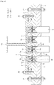
- a raw material feeder is, as shown in Fig. 1 , a raw material feeder to distribute and feed a liquid compound as a raw material to a plurality of evaporation tubes 8 of a falling film evaporator.
- the raw material feeder comprises a main body section 51 comprising a plurality of communication holes 50 facing the plurality of evaporation tubes 8, a restriction orifice 7 housed in an interior of each of the communication holes 50 comprising an orifice hole 7a, a liquid feeding tip 6 housed to face the restriction orifice 7 on an upstream side of the restriction orifice 7 in the interior of the communication hole 50, comprising a hole portion 6a facing the orifice hole 7a, a first O-ring 10 fitted into a side surface of the liquid feeding tip 6 from outside, sandwiched between the side surface of the liquid feeding tip 6 and an inner surface of the communication hole 50, and a second O-ring 11 sandwiched between the liquid feeding tip 6 and the restriction orifice 7 so that the orifice hole 7
- a first O-ring groove may be provided in which the first O-ring 10 is to be mounted. Furthermore, a surface of the liquid feeding tip 6 that faces the restriction orifice 7 may be provided with a second O-ring groove in which the second O-ring 11 is to be mounted.
- the main body section 51 comprises a first flange 2 and a second flange 3, and further comprises a feeding flange 1 comprising a raw material feeding port 1a to feed the raw material, the feeding flange 1 being provided on the first flange 2.
- the first O-ring 10 inhibits the raw material from flowing through a space between the side surface of the liquid feeding tip 6 and the inner surface of the communication hole 50.
- the second O-ring 11 inhibits the raw material from flowing through a space between the liquid feeding tip 6 and the restriction orifice 7. That is, the first O-ring 10 and the second O-ring 11 inhibit the raw material so that the raw material flows only through the orifice hole 7a.
- Examples of a material of the first O-ring 10 and the second O-ring 11 include ethylene propylene diene rubber (EPDM) and silicone rubber, from viewpoints of resistance to the raw material, heat resistance and durability.
- EPDM ethylene propylene diene rubber
- silicone rubber from viewpoints of resistance to the raw material, heat resistance and durability.
- the communication holes 50 as many as the evaporation tubes 8 to feed the raw material are prepared.
- a diameter of a downstream end of the communication hole 50 is determined in accordance with a tube diameter of each of the evaporation tubes 8 to which the raw material is fed.
- a hole diameter of the orifice hole 7a provided in the restriction orifice 7 may be set to an optimum hole diameter in accordance with a flow velocity of the raw material to be distributed through the evaporation tubes 8 and a number of the evaporation tubes 8 for use.
- the hole diameter of the orifice hole 7a is set so that a flow rate coefficient ⁇ calculated with the following equation (1) is preferably from 0.50 to 1.00, more preferably from 0.60 to 0.85, and further preferably from 0.65 to 0.75.
- Flow rate coefficient ⁇ Q / A ⁇ 2 ⁇ ⁇ P / ⁇ 0.5
- Equation (1) "Q” is a volumetric flow rate (m 3 /s) that means a volume of a fluid flowing through the orifice hole 7a per unit time, "A” is a cross-sectional area (m 2 ) of the orifice hole 7a, “ ⁇ P” is pressure loss (Pa) per unit flow rate of the fluid passing through the orifice hole 7a, and “p” is a density (kg/m 3 ) of the raw material passing through the orifice hole 7a.
- the flow rate coefficient ⁇ is measured in advance to prepare a required number of orifice holes 7a having less variations, so that the raw material can be dispersed more evenly.
- a range of a flow velocity of the raw material to be distributed through the orifice hole 7a can be set to be more than or equal to a range in which a differential pressure before and after the distribution of the raw material through the orifice hole 7a is not zero, and a range less than or equal to a feeding pressure upper limit.
- the range of the flow velocity of the raw material to be distributed through the orifice hole 7a can be set in accordance with the hole diameter of the orifice hole 7a. Therefore, from a viewpoint that the flow velocity meets operation conditions, the hole diameter of the orifice hole 7a is preferably from 0.10 to 1.0 mm, more preferably from 0.15 to 0.9 mm, and further preferably from 0.20 to 0.8 mm.
- the raw material feeder according to the embodiment of the present invention comprises a nozzle 5 housed to face the restriction orifice 7 on a downstream side of the restriction orifice 7 in an interior of the communication hole 50, comprising a nozzle hole 5a facing the orifice hole 7a, and a third O-ring 12 sandwiched between the nozzle 5 and the restriction orifice 7 so that the orifice hole 7a is present in an inner region.
- a third O-ring groove may be provided in which the third O-ring 12 is to be mounted.
- the third O-ring 12 inhibits the raw material from flowing through a space between the nozzle 5 and the restriction orifice 7. That is, the third O-ring 12 inhibits the raw material so that the raw material flows only through the orifice hole 7a.
- the same material as the above material of the first O-ring 10 and second O-ring 11 may be used.
- the nozzle hole 5a is configured to house a liquid diffuser 30 in an interior.
- fixing means for the liquid diffuser 30 include means for holding the liquid diffuser 30 with an inner wall surface of the nozzle hole 5a to fix the diffuser and means for integrally forming the liquid diffuser 30 in the nozzle hole 5a to fix the diffuser.
- the liquid diffuser 30 is formed in a shape with a gap between the diffuser and the nozzle 5, as shown in Fig. 3 , in order to diffuse the raw material distributed through the orifice hole 7a and distribute the raw material along an inner wall surface of the nozzle 5.
- the diffuser 30 may have a quadrangular shape shown in Fig. 3 , a triangular shape, a polygonal shape, or the like.
- the nozzle hole 5a comprises an upstream hole portion 5b on an upstream side and a downstream hole portion 5c communicating with a downstream end of the upstream hole portion 5b and having a diameter increasing toward a lower end of the nozzle 5, and the liquid diffuser 30 is housed in the upstream hole portion 5b.
- the liquid diffuser 30 diffuses the raw material distributed through the orifice hole 7a in the upstream hole portion 5b, and further diffuses the raw material in the downstream hole portion 5c having the diameter increasing toward the lower end of the nozzle 5, so that the raw material can be uniformly and stably distributed to an inner wall surface of the evaporation tube 8.
- the main body section 51 comprises the first flange 2 comprising a first hole portion 2a, and the second flange 3 facing a surface of the first flange 2 on a downstream side comprising a second hole portion 3a communicating with the first hole portion 2a, and the first hole portion 2a and the second hole portion 3a form the communication hole 50.
- the second hole portion 3a comprises a large diameter hole 3b on the upstream side, and a small diameter hole 3c communicating with the large diameter hole 3b, having a diameter smaller than a diameter of the large diameter hole 3b, a side portion of the nozzle 5 on the upstream side is a protrusion 5d protruding outward, and the protrusion 5d abuts on a bottom surface of the large diameter hole 3b on the downstream side.
- the nozzle 5 can be stably installed in the second flange 3.
- a circumferential surface of the first hole portion 2a of the first flange 2 on the downstream side may be cut and provided with a female thread, and a circumferential surface of the liquid feeding tip 6 on the downstream side may be cut and provided with a male thread. Consequently, the liquid feeding tip 6 can be screwed to the first hole portion 2a.
- the first O-ring 10 may be mounted to a side surface of the liquid feeding tip 6 on the upstream side that is not cut or provided with the male screw and may be sandwiched between this side surface and a circumferential surface of the first hole portion 2a of the first flange 2 on the upstream side that is not cut or provided with the female screw.
- downstream end of the nozzle 5 extends to a downstream side of a downstream end of the second flange 3. Consequently, the downstream end of the nozzle 5 can extend into the evaporation tube 8 of an evaporator 4, and the raw material can be securely guided into the evaporation tube 8.
- the feeding flange 1, the first flange 2 and the second flange 3 are prepared.
- the liquid feeding tip 6, the first O-ring 10 and the second O-ring 11 are prepared, and the first O-ring 10 and the second O-ring 11 are mounted to the liquid feeding tip 6. Then, the liquid feeding tip 6 to which the first O-ring 10 and the second O-ring 11 are mounted is disposed in the first hole portion 2a of the first flange 2.
- the nozzle 5 and the third O-ring 12 are next prepared, and the third O-ring 12 is mounted to the nozzle 5. Then, the nozzle 5 to which the third O-ring 12 is mounted is disposed in the second hole portion 3a of the second flange 3.
- restriction orifice 7 is then prepared and the restriction orifice 7 is disposed on the nozzle 5 disposed in the second flange 3.
- first flange 2 is disposed on the second flange 3.
- the arranged first flange 2 and second flange 3 are fixed with a fixing member such as a bolt (not shown).
- a fixing member such as a bolt (not shown).
- the liquid feeding tip 6 is then tightened by using a tool corresponding to a tool engagement portion 6b such as a hexagonal hole provided in the hole portion 6a of the liquid feeding tip 6 on an upstream side to seal the restriction orifice 7.
- a tool engagement portion 6b such as a hexagonal hole provided in the hole portion 6a of the liquid feeding tip 6 on an upstream side to seal the restriction orifice 7.
- the feeding flange 1 is disposed on the first flange 2.
- the arranged feeding flange 1, first flange 2 and second flange 3 are fixed with a fixing member 20 such as a bolt to form the raw material feeder according to the embodiment of the present invention.
- a fixing member 20 such as a bolt to form the raw material feeder according to the embodiment of the present invention.
- the raw material feeder is disposed in the evaporator 4 comprising a flange comprising a plurality of communication holes and the plurality of evaporation tubes 8 mounted to the communication holes.
- positions of the communication holes of the raw material feeder are matched with positions of the communication holes of the evaporator 4.
- the arranged raw material feeder and evaporator 4 are fixed with fixing members 21 such as bolts to complete installation.
- Fig. 4 shows a schematic overall diagram of a production device comprising a falling film evaporator in which the raw material feeder according to the embodiment of the present invention is installed.
- the production device shown in Fig. 4 comprises a raw material tank 100, a raw material feeder 101, an evaporator (the falling film evaporator) 102, a thermal decomposition reactor 103, a reaction solution receiver 104, and a reaction solution storage tank 105.
- a temperature adjustment device for example, configured to distribute heat medium through a jacket structure is provided, and temperatures of the evaporator 102 and the thermal decomposition reactor 103 can be adjusted with the temperature adjustment device.
- a pressure adjustment device such as a pressure pump is provided, and pressures of the raw material tank 100 and the raw material feeder 101 (the upstream side of the restriction orifice 7) can be adjusted on pressurizing conditions with the pressure adjustment device.
- a pressure adjustment device such as a pressure pump is provided, and pressures of the raw material feeder 101 (the downstream side of the restriction orifice 7), the evaporator 102, the thermal decomposition reactor 103 and the reaction solution receiver 104 can be adjusted on decompression conditions with the pressure adjustment device.
- a method of producing N-vinylcarboxylic acid amide according to the embodiment of the present invention comprises a feeding step S1, an evaporation step S2, and a thermal decomposition step S3.
- a feeding step S1 an evaporation step S2
- a thermal decomposition step S3 a thermal decomposition step S3.
- the feeding step S1 is a step of feeding, by the raw material feeder according to the embodiment of the present invention, a liquid compound of N-(1-alkoxyethyl)carboxylic acid amide as the raw material to the evaporator 4.
- raw material liquid fed from the raw material feeding port 1a is fed through the feeding flange 1 to the first flange 2.
- Gas (air) mixed in the raw material during the liquid feeding is discharged through a gas vent 9.
- the raw material liquid is distributed to all installed liquid feeding tips 6 and fed to the restriction orifices 7 of the second flange 3.
- the raw material liquid passed through the restriction orifices 7 is introduced at an almost even flow velocity into the respective evaporation tubes 8 of the evaporator 4.
- a feeding speed of the raw material to the evaporator is preferably from 5 to 350 kg/h, more preferably from 10 to 150 kg/h, and further preferably from 15 to 80 kg/h.
- the feeding speed of the raw material to the evaporator is in the above range, so that raw material dispersibility to the plurality of the evaporation tubes of the evaporator can be maintained, and the raw material can be stably evaporated.
- the raw material feeder feeds the raw material to each of the plurality of evaporation tubes at a flow rate variation coefficient of preferably 10.0% or less, more preferably 9.0% or less, and further preferably 8.0% or less.
- An upper limit of the variation coefficient of the flow rate is the above numeric value, so that the raw material dispersibility to the plurality of evaporation tubes of the evaporator can be maintained, and the raw material can be stably evaporated.
- the variation coefficient of the flow rate the flow rate of the raw material fed to each of the plurality of evaporation tubes in a certain time is measured, and a standard deviation to an average value of flow rates in all the evaporation tubes is calculated.
- the coefficient indicates a degree of flow rate variation obtained from the standard deviation.
- the variation coefficient of the flow rate is a coefficient calculated with the standard deviation ⁇ the average value ⁇ 100(%).
- the raw material feeder feeds the raw material to each of the plurality of evaporation tubes with a flow rate error of preferably - 20% or more and +30% or less, more preferably -15% or more and +25% or less, and further preferably -10% or more and +20% or less.
- the error of the flow rate is in the above range, so that the raw material dispersibility to the plurality of evaporation tubes of the evaporator can be maintained, and the raw material can be stably evaporated.
- the flow rate of the raw material fed to each of the plurality of evaporation tubes in a certain time is measured, and a relative error to the average value of the flow rates in all the evaporation tubes is calculated.
- the raw material feeder feeds the raw material to each of the plurality of evaporation tubes at a flow velocity of preferably 2.0 g/min or more and 80.0 g/min or less, more preferably 2.5 g/min or more and 78.0 g/min or less, and further preferably 3.0 g/min or more and 76.0 g/min or less.
- the flow velocity is in the above range, so that the raw material dispersibility to the plurality of evaporation tubes of the evaporator can be maintained, and the raw material can be stably evaporated.
- N-(1-alkoxyethyl)carboxylic acid amide represented by the following general formula (I) is used as the raw material.
- R 1 represents a C 1 to C 5 alkyl group
- R 2 represents a hydrogen atom or a C 1 to C 5 alkyl group
- R 3 represents a C 1 to C 5 alkyl group.
- N-(1-alkoxyethyl)carboxylic acid amide examples include N-(1-methoxyethyl)acetamide, N-(1-methoxyethyl)-N-methylacetamide, N-(1-ethoxyethyl)acetamide, N-(1-ethoxyethyl)-N-methylacetamide, N-(1-propxyethyl)acetamide, N-(1-isopropoxyethyl)acetamide, N-(1-butoxyethyl)acetamide, N-(1-isobutoxyethyl)acetamide, N-(1-methoxyethyl)propionamide, N-(1-ethoxyethyl)propionamide, N-(1-propoxyethyl)propionamide, N-(1-isopropoxyethyl)propionamide, N-(1-buthoxyethyl)propionamide, N-
- the examples preferably include N-(1-methoxyethyl)acetamide, N-(1-isopropxyethyl)acetamide and N-(1-methoxyethyl)isobutylamide, and more preferably include N-(1-methoxyethyl)acetamide.
- the evaporation step S2 is a step of evaporating, by the evaporator, the raw material, to form a vaporized raw material.
- the evaporation step S2 can be performed under reduced pressure or under normal pressure and is preferably performed under reduced pressure. Specifically, the evaporation step S2 is performed with a reaction pressure preferably from 1 to 30 kPa, more preferably from 3 to 25 kPa, and further preferably from 5 to 20 kPa.
- the evaporation step S2 is required to be performed specifically at a temperature to evaporate and vaporize the raw material, preferably from 100 to 200°C, more preferably from 110 to 190°C, and further preferably from 120 to 180°C.
- the thermal decomposition step S3 is a step of feeding the vaporized raw material to a thermal decomposition reactor to thermally decompose the raw material.
- a thermal decomposition reactor to thermally decompose the raw material.
- the flow may be ascending flow or descending flow.
- the thermal decomposition step S3 can be performed under reduced pressure or under normal pressure and is preferably performed under reduced pressure. Specifically, the thermal decomposition step S3 is performed with a reaction pressure preferably from 1 to 30 kPa, more preferably from 3 to 25 kPa, and further preferably from 5 to 20 kPa.
- the thermal decomposition step S3 is performed specifically at a temperature preferably from 250 to 500°C, more preferably from 300 to 480°C, and further preferably from 350 to 450°C.
- a staying time in the thermal decomposition step S3 is preferably from 0.1 to 10 seconds, more preferably from 0.2 to 9 seconds, and further preferably from 0.3 to 8 seconds.
- the thermal decomposition reactor has a multi-tube structure.
- a reactant thermal decomposed in the thermal decomposition step S3 is cooled to be liquefied and sent to a reaction solution receiver.
- the reactant stored in the reaction solution receiver is sent to and stored in a reaction solution storage tank.
- N-vinylcarboxylic acid amide obtained by the above steps is represented by the following general formula (II) and corresponds to N-(1-alkoxyethyl)carboxylic acid amide that is a suitable raw material represented by the general formula (I).
- R 2 represents a hydrogen atom or C 1 to C 5 alkyl group
- R 3 represents a C 1 to C 5 alkyl group.
- N-vinylcarboxylic acid amide examples include N-vinylacetamide, N-methyl-N-vinylacetamide, N-vinylpropionamide, N-methyl-N-vinylpropionamide, N-vinylisobutylamide and N-methyl-N-vinylisobutylamide, and preferably include N-vinylacetamide.
- a raw material feeder shown in Fig. 1 was installed in a shell and tube evaporator comprising 22 evaporation tubes (tubes) each having a diameter of 25.4 mm and a length of 2500 mm.
- a restriction orifice of the raw material feeder was prepared in a hole diameter of 0.25 mm.
- a flow rate coefficient ⁇ of the restriction orifice was measured, and 22 restriction orifices having a flow rate coefficient ⁇ of 0.7 were selected and incorporated in the raw material feeder.
- N-(1-methoxyethyl)acetamide was continuously fed to the raw material feeder to carry out distribution test.
- Example 2 A device similar to that of Example 1 was used, and N-(1-methoxyethyl)acetamide was continuously fed to a raw material feeder at a speed of 833 g/min for 5 minutes to carry out distribution test.
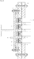
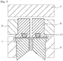
- a conventional raw material feeder shown in Figs. 6 , 7 was installed in the same shell and tube evaporator as in Example 1.
- the conventional raw material feeder is different from the raw material feeder shown in Fig. 1 in that a first O-ring 10 and a third O-ring 12 are not provided.
- a restriction orifice of the conventional raw material feeder was prepared in a hole diameter of 0.25 mm.
- a flow rate coefficient ⁇ of the restriction orifice was measured, and 22 restriction orifices having the flow rate coefficient ⁇ of 0.7 were selected and incorporated in the conventional raw material feeder.
- N-(1-methoxyethyl)acetamide was continuously fed to the conventional raw material feeder to carry out distribution test.
- a distributor type raw material distribution device was installed in the same shell and tube evaporator as in Example 1.
- 22 holes each having ⁇ 2 mm were provided in correspondence to respective evaporation tubes.
- N-(1-methoxyethyl)acetamide was continuously fed to the distributor type raw material distribution device to carry out distribution test.
- N-(1-methoxyethyl)acetamide was collected only from two evaporation tubes and was not evenly distributed or fed.
- a raw material feeder of the present invention for example, one-sided flow of a raw material does not occur even at a speed less than or equal to a feeding speed at which performance of a distributor (distribution plate) system can be maintained. That is, by use of the raw material feeder of the present invention, even at a low raw material feeding speed in production of N-vinylcarboxylic acid amide, the raw material can be fed with stabilized raw material dispersibility to a plurality of evaporation tubes of a falling film evaporator, a problem of a thermal decomposition reactor being blocked due to coagulum can be inhibited, and a continuous operation can be stably performed for a long period of time.
- N-vinylcarboxylic acid amide obtained in a production method in which a raw material feeder is used is a useful monomer in production of N-vinylcarboxylic acid amide polymer to be used in a coagulant, a liquid absorbent, a thickener, or the like, and additionally in various industrial applications.
Landscapes
- Chemical & Material Sciences (AREA)
- Chemical Kinetics & Catalysis (AREA)
- Organic Chemistry (AREA)
- Organic Low-Molecular-Weight Compounds And Preparation Thereof (AREA)
- Heat-Exchange Devices With Radiators And Conduit Assemblies (AREA)
- Vaporization, Distillation, Condensation, Sublimation, And Cold Traps (AREA)
- Feeding, Discharge, Calcimining, Fusing, And Gas-Generation Devices (AREA)
Abstract
Description
- The present invention relates to a raw material feeder to distribute and feed a liquid compound as a raw material to a plurality of evaporation tubes of a falling film evaporator, and a method of producing N-vinylcarboxylic acid amide in which N-(1-alkoxyethyl)carboxylic acid amide is used as a raw material.
- In relation to methods of producing N-vinylcarboxylic acid amide, a large number of methods have been proposed (see
PTL 1, for example). In a production method described inPTL 1, a method of producing N-vinylcarboxylic acid amide involving evaporating and thermally decomposing a raw material of N-(2-alkoxyethyl)carboxylic acid amide is disclosed. - Thus, in the method of producing N-vinylcarboxylic acid amide by thermal decomposition, an important factor for stable operation is to stably evaporate the raw material in an evaporator and to introduce the material into a thermal decomposition reactor. Therefore, to stably evaporate the raw material, a multi-tube falling film evaporator comprising a plurality of evaporation tubes is typically used as the evaporator.
- For feeding of the raw material to the evaporator and distribution of the raw material to the plurality of evaporation tubes, a distributor (a distribution plate) system and a spray nozzle system are typically used, but these systems require a corresponding raw material feeding speed. If the speed is less than or equal to the feeding speed at which this performance can be maintained, raw material dispersibility drops. If the raw material dispersibility drops, for example, one-sided flow of the raw material occurs to hinder sufficient evaporation, and a liquid raw material flows into the thermal decomposition reactor. The inflow of the liquid raw material into the thermal decomposition reactor at a high temperature might generate tar or solid aggregates (referred to also as coagulum). The generation of coagulum results in a problem of the thermal decomposition reactor being blocked, thereby making it difficult to perform the stable operation.
- PTL 1:
WO 2017/002494 (A1 ) - An object of the present invention is to solve the above problems and provide a raw material feeder and a method of producing N-vinylcarboxylic acid amide in which a raw material is fed to a plurality of evaporation tubes of a falling film evaporator with a stable raw material dispersibility, so that a problem of a thermal decomposition reactor being blocked due to coagulum can be inhibited, and an operation can be stably and continuously performed for a long period of time.
- The present invention relates to the following.
- (1) A raw material feeder to distribute and feed a liquid compound as a raw material to a plurality of evaporation tubes of a falling film evaporator, the raw material feeder comprising: a main body section comprising a plurality of communication holes facing the plurality of evaporation tubes, a restriction orifice housed in an interior of each of the communication holes, and comprising an orifice hole, a liquid feeding tip housed to face the restriction orifice on an upstream side of the restriction orifice in the interior of the communication hole, and comprising a hole portion facing the orifice hole, a first O-ring fitted into a side surface of the liquid feeding tip from outside, and sandwiched between the side surface of the liquid feeding tip and an inner surface of the communication hole, and a second O-ring sandwiched between the liquid feeding tip and the restriction orifice so that the orifice hole is present in an inner region.
- (2) The raw material feeder according to (1), wherein the liquid compound is N-(1-alkoxyethyl)carboxylic acid amide.
- (3) The raw material feeder according to (1) or (2), further comprising: a nozzle housed to face the restriction orifice on a downstream side of the restriction orifice in an interior of the communication hole, and comprising a nozzle hole facing the orifice hole, and a third O-ring sandwiched between the nozzle and the restriction orifice so that the orifice hole is present in an inner region.
- (4) The raw material feeder according to (3), wherein the nozzle hole houses a liquid diffuser in an interior.
- (5) The raw material feeder according to (3) or (4), wherein the nozzle hole comprises an upstream hole portion on an upstream side, and a downstream hole portion communicating with a downstream end of the upstream hole portion, and having a diameter increasing toward a lower end of the nozzle, and the liquid diffuser is housed in the upstream hole portion.
- (6) The raw material feeder according to any one of (3) to (5), wherein the main body section comprises a first flange comprising a first hole portion, and a second flange facing a surface of the first flange on a downstream side, and comprising a second hole portion facing the first hole portion, the first hole portion and the second hole portion form the communication hole, the second hole portion comprises a large diameter hole on an upstream side, and a small diameter hole communicating with the large diameter hole, and having a diameter smaller than a diameter of the large diameter hole, a side portion of the nozzle on the upstream side is a protrusion protruding outward, and the protrusion abuts on a bottom surface of the large diameter hole on the downstream side.
- (7) A method of producing N-vinylcarboxylic acid amide comprising: a feeding step of feeding, by the raw material feeder according to any one of (1) to (6), N-(1-alkoxyethyl)carboxylic acid amide as a raw material to a falling film evaporator, an evaporation step of evaporating, by the falling film evaporator, the raw material, to form a vaporized raw material, and a thermal decomposition step of feeding the vaporized raw material to a thermal decomposition reactor, to thermally decompose the raw material under reduced pressure.
- (8) The method of producing N-vinylcarboxylic acid amide according to (7), wherein the evaporation step is performed under reduced pressure.
- (9) The method of producing N-vinylcarboxylic acid amide according to (7) or (8), wherein the thermal decomposition step is performed under reduced pressure.
- (10) The method of producing N-vinylcarboxylic acid amide according to any one of (7) to (9), wherein the raw material feeder feeds the raw material to each of the plurality of evaporation tubes with a flow rate variation coefficient of 10.0% or less.
- (11) The method of producing N-vinylcarboxylic acid amide according to any one of (7) to (10), wherein the raw material feeder feeds the raw material to each of the plurality of evaporation tubes with a flow rate error of -20% or more and +30% or less.
- (12) The method of producing N-vinylcarboxylic acid amide according to any one of (7) to (11), wherein the raw material feeder feeds the raw material to each of the plurality of evaporation tubes at a flow velocity of 2.0 g/min or more and 80.0 g/min or less.
- (13) The method of producing N-vinylcarboxylic acid amide according to any one of (7) to (12), wherein the N-(1-alkoxyethyl)carboxylic acid amide is N-(1-methoxyethyl)acetamide.
- According to the present invention, a raw material feeder and a method of producing N-vinylcarboxylic acid amide can be provided in which a raw material is fed to a plurality of evaporation tubes of a falling film evaporator with a stable raw material dispersibility, so that a problem of a thermal decomposition reactor being blocked due to coagulum can be inhibited, and an operation can be stably and continuously performed for a long period of time.
-
- [
Fig. 1] Fig. 1 is a schematic cross-sectional view (an overall view) of a raw material feeder according to an embodiment of the present invention. - [
Fig. 2] Fig. 2 is a schematic cross-sectional view (an enlarged view) of the raw material feeder according to the embodiment of the present invention. - [
Fig. 3] Fig. 3 is a cross-sectional view in an A-A direction ofFig. 2 . - [
Fig. 4] Fig. 4 is a schematic overall diagram of a production device to produce N-vinylcarboxylic acid amide of the present invention. - [
Fig. 5] Fig. 5 is a flowchart showing a method of producing N-vinylcarboxylic acid amide of the present invention. - [
Fig. 6] Fig. 6 is a schematic cross-sectional view (an overall view) of a conventional raw material feeder shown as a comparative example. - [
Fig. 7] Fig. 7 is a schematic cross-sectional view (an enlarged view) of the conventional raw material feeder shown as the comparative example. - A raw material feeder according to an embodiment of the present invention is, as shown in
Fig. 1 , a raw material feeder to distribute and feed a liquid compound as a raw material to a plurality ofevaporation tubes 8 of a falling film evaporator. The raw material feeder comprises a main body section 51 comprising a plurality ofcommunication holes 50 facing the plurality ofevaporation tubes 8, arestriction orifice 7 housed in an interior of each of thecommunication holes 50 comprising anorifice hole 7a, aliquid feeding tip 6 housed to face therestriction orifice 7 on an upstream side of therestriction orifice 7 in the interior of thecommunication hole 50, comprising ahole portion 6a facing theorifice hole 7a, a first O-ring 10 fitted into a side surface of theliquid feeding tip 6 from outside, sandwiched between the side surface of theliquid feeding tip 6 and an inner surface of thecommunication hole 50, and a second O-ring 11 sandwiched between theliquid feeding tip 6 and therestriction orifice 7 so that theorifice hole 7a is present in an inner region. An example of the liquid compound is N-(1-alkoxyethyl)carboxylic acid amide. - In the side surface of the
liquid feeding tip 6, a first O-ring groove may be provided in which the first O-ring 10 is to be mounted. Furthermore, a surface of theliquid feeding tip 6 that faces therestriction orifice 7 may be provided with a second O-ring groove in which the second O-ring 11 is to be mounted. - The main body section 51 comprises a
first flange 2 and asecond flange 3, and further comprises afeeding flange 1 comprising a rawmaterial feeding port 1a to feed the raw material, thefeeding flange 1 being provided on thefirst flange 2. - The first O-
ring 10 inhibits the raw material from flowing through a space between the side surface of theliquid feeding tip 6 and the inner surface of thecommunication hole 50. The second O-ring 11 inhibits the raw material from flowing through a space between theliquid feeding tip 6 and therestriction orifice 7. That is, the first O-ring 10 and the second O-ring 11 inhibit the raw material so that the raw material flows only through theorifice hole 7a. - Examples of a material of the first O-
ring 10 and the second O-ring 11 include ethylene propylene diene rubber (EPDM) and silicone rubber, from viewpoints of resistance to the raw material, heat resistance and durability. - The
communication holes 50 as many as theevaporation tubes 8 to feed the raw material are prepared. A diameter of a downstream end of thecommunication hole 50 is determined in accordance with a tube diameter of each of theevaporation tubes 8 to which the raw material is fed. - A hole diameter of the
orifice hole 7a provided in therestriction orifice 7 may be set to an optimum hole diameter in accordance with a flow velocity of the raw material to be distributed through theevaporation tubes 8 and a number of theevaporation tubes 8 for use. - The hole diameter of the
orifice hole 7a is set so that a flow rate coefficient α calculated with the following equation (1) is preferably from 0.50 to 1.00, more preferably from 0.60 to 0.85, and further preferably from 0.65 to 0.75.
- In Equation (1), "Q" is a volumetric flow rate (m3/s) that means a volume of a fluid flowing through the
orifice hole 7a per unit time, "A" is a cross-sectional area (m2) of theorifice hole 7a, "ΔP" is pressure loss (Pa) per unit flow rate of the fluid passing through theorifice hole 7a, and "p" is a density (kg/m3) of the raw material passing through theorifice hole 7a. - For a purpose of decreasing an error in hole diameter of the
orifice hole 7a, the flow rate coefficient α is measured in advance to prepare a required number oforifice holes 7a having less variations, so that the raw material can be dispersed more evenly. - A range of a flow velocity of the raw material to be distributed through the
orifice hole 7a can be set to be more than or equal to a range in which a differential pressure before and after the distribution of the raw material through theorifice hole 7a is not zero, and a range less than or equal to a feeding pressure upper limit. The range of the flow velocity of the raw material to be distributed through theorifice hole 7a can be set in accordance with the hole diameter of theorifice hole 7a. Therefore, from a viewpoint that the flow velocity meets operation conditions, the hole diameter of theorifice hole 7a is preferably from 0.10 to 1.0 mm, more preferably from 0.15 to 0.9 mm, and further preferably from 0.20 to 0.8 mm. - It is preferable that, as shown in
Fig. 1 , the raw material feeder according to the embodiment of the present invention comprises anozzle 5 housed to face therestriction orifice 7 on a downstream side of therestriction orifice 7 in an interior of thecommunication hole 50, comprising anozzle hole 5a facing theorifice hole 7a, and a third O-ring 12 sandwiched between thenozzle 5 and therestriction orifice 7 so that theorifice hole 7a is present in an inner region. - In a surface of the
nozzle 5 that faces therestriction orifice 7, a third O-ring groove may be provided in which the third O-ring 12 is to be mounted. - The third O-
ring 12 inhibits the raw material from flowing through a space between thenozzle 5 and therestriction orifice 7. That is, the third O-ring 12 inhibits the raw material so that the raw material flows only through theorifice hole 7a. - As a material of the third O-
ring 12, the same material as the above material of the first O-ring 10 and second O-ring 11 may be used. - It is preferable that, as shown in
Fig. 1 andFig. 2 , thenozzle hole 5a is configured to house aliquid diffuser 30 in an interior. There are not any special restrictions on fixing means for theliquid diffuser 30. Examples of the fixing means include means for holding theliquid diffuser 30 with an inner wall surface of thenozzle hole 5a to fix the diffuser and means for integrally forming theliquid diffuser 30 in thenozzle hole 5a to fix the diffuser. Theliquid diffuser 30 is formed in a shape with a gap between the diffuser and thenozzle 5, as shown inFig. 3 , in order to diffuse the raw material distributed through theorifice hole 7a and distribute the raw material along an inner wall surface of thenozzle 5. There are not any special restrictions on a cross-sectional shape of theliquid diffuser 30 as long as the diffuser is formed in the shape with the gap between the diffuser and thenozzle 5. The diffuser may have a quadrangular shape shown inFig. 3 , a triangular shape, a polygonal shape, or the like. - A configuration is preferable in which, as shown in
Fig. 2 , thenozzle hole 5a comprises anupstream hole portion 5b on an upstream side and adownstream hole portion 5c communicating with a downstream end of theupstream hole portion 5b and having a diameter increasing toward a lower end of thenozzle 5, and theliquid diffuser 30 is housed in theupstream hole portion 5b. According to this configuration, theliquid diffuser 30 diffuses the raw material distributed through theorifice hole 7a in theupstream hole portion 5b, and further diffuses the raw material in thedownstream hole portion 5c having the diameter increasing toward the lower end of thenozzle 5, so that the raw material can be uniformly and stably distributed to an inner wall surface of theevaporation tube 8. - As shown in
Fig. 1 andFig. 2 , the main body section 51 comprises thefirst flange 2 comprising afirst hole portion 2a, and thesecond flange 3 facing a surface of thefirst flange 2 on a downstream side comprising asecond hole portion 3a communicating with thefirst hole portion 2a, and thefirst hole portion 2a and thesecond hole portion 3a form thecommunication hole 50. A configuration is preferable in which thesecond hole portion 3a comprises alarge diameter hole 3b on the upstream side, and asmall diameter hole 3c communicating with thelarge diameter hole 3b, having a diameter smaller than a diameter of thelarge diameter hole 3b, a side portion of thenozzle 5 on the upstream side is aprotrusion 5d protruding outward, and theprotrusion 5d abuts on a bottom surface of thelarge diameter hole 3b on the downstream side. According to this configuration, thenozzle 5 can be stably installed in thesecond flange 3. - A circumferential surface of the
first hole portion 2a of thefirst flange 2 on the downstream side may be cut and provided with a female thread, and a circumferential surface of theliquid feeding tip 6 on the downstream side may be cut and provided with a male thread. Consequently, theliquid feeding tip 6 can be screwed to thefirst hole portion 2a. In this case, the first O-ring 10 may be mounted to a side surface of theliquid feeding tip 6 on the upstream side that is not cut or provided with the male screw and may be sandwiched between this side surface and a circumferential surface of thefirst hole portion 2a of thefirst flange 2 on the upstream side that is not cut or provided with the female screw. - It is preferable that, as shown in
Fig. 2 , the downstream end of thenozzle 5 extends to a downstream side of a downstream end of thesecond flange 3. Consequently, the downstream end of thenozzle 5 can extend into theevaporation tube 8 of an evaporator 4, and the raw material can be securely guided into theevaporation tube 8. - Hereinafter, description will be made as to an installation method of the raw material feeder according to the embodiment of the present invention with reference to
Fig. 1 . - First, the feeding
flange 1, thefirst flange 2 and thesecond flange 3 are prepared. - Next, the
liquid feeding tip 6, the first O-ring 10 and the second O-ring 11 are prepared, and the first O-ring 10 and the second O-ring 11 are mounted to theliquid feeding tip 6. Then, theliquid feeding tip 6 to which the first O-ring 10 and the second O-ring 11 are mounted is disposed in thefirst hole portion 2a of thefirst flange 2. - The
nozzle 5 and the third O-ring 12 are next prepared, and the third O-ring 12 is mounted to thenozzle 5. Then, thenozzle 5 to which the third O-ring 12 is mounted is disposed in thesecond hole portion 3a of thesecond flange 3. - The
restriction orifice 7 is then prepared and therestriction orifice 7 is disposed on thenozzle 5 disposed in thesecond flange 3. - Next, the
first flange 2 is disposed on thesecond flange 3. The arrangedfirst flange 2 andsecond flange 3 are fixed with a fixing member such as a bolt (not shown). At this time, it is preferable to seal a space between thefirst flange 2 and thesecond flange 3 with an O-ring in order to improve close contact therebetween. - The
liquid feeding tip 6 is then tightened by using a tool corresponding to atool engagement portion 6b such as a hexagonal hole provided in thehole portion 6a of theliquid feeding tip 6 on an upstream side to seal therestriction orifice 7. - Subsequently, the feeding
flange 1 is disposed on thefirst flange 2. The arrangedfeeding flange 1,first flange 2 andsecond flange 3 are fixed with a fixingmember 20 such as a bolt to form the raw material feeder according to the embodiment of the present invention. At this time, it is preferable to seal a space between the feedingflange 1 and thefirst flange 2 by use of an O-ring in order to improve close contact therebetween. - Next, the raw material feeder is disposed in the evaporator 4 comprising a flange comprising a plurality of communication holes and the plurality of
evaporation tubes 8 mounted to the communication holes. When disposing the raw material feeder, positions of the communication holes of the raw material feeder are matched with positions of the communication holes of the evaporator 4. Then, the arranged raw material feeder and evaporator 4 are fixed with fixingmembers 21 such as bolts to complete installation. At this time, it is preferable to seal a space between the raw material feeder (the second flange 3) and the evaporator 4 by use of a spiral gasket in order to improve close contact therebetween. -
Fig. 4 shows a schematic overall diagram of a production device comprising a falling film evaporator in which the raw material feeder according to the embodiment of the present invention is installed. - The production device shown in
Fig. 4 comprises araw material tank 100, araw material feeder 101, an evaporator (the falling film evaporator) 102, athermal decomposition reactor 103, a reaction solution receiver 104, and a reactionsolution storage tank 105. - In the
evaporator 102 and thethermal decomposition reactor 103, a temperature adjustment device, for example, configured to distribute heat medium through a jacket structure is provided, and temperatures of theevaporator 102 and thethermal decomposition reactor 103 can be adjusted with the temperature adjustment device. - In the
raw material tank 100, a pressure adjustment device such as a pressure pump is provided, and pressures of theraw material tank 100 and the raw material feeder 101 (the upstream side of the restriction orifice 7) can be adjusted on pressurizing conditions with the pressure adjustment device. - In the reaction solution receiver 104, a pressure adjustment device such as a pressure pump is provided, and pressures of the raw material feeder 101 (the downstream side of the restriction orifice 7), the
evaporator 102, thethermal decomposition reactor 103 and the reaction solution receiver 104 can be adjusted on decompression conditions with the pressure adjustment device. - As shown in
Fig. 5 , a method of producing N-vinylcarboxylic acid amide according to the embodiment of the present invention comprises a feeding step S1, an evaporation step S2, and a thermal decomposition step S3. Hereinafter, the method of producing N-vinylcarboxylic acid amide according to the embodiment of the present invention will be described in detail. - The feeding step S1 is a step of feeding, by the raw material feeder according to the embodiment of the present invention, a liquid compound of N-(1-alkoxyethyl)carboxylic acid amide as the raw material to the evaporator 4.
- In the feeding step S1, raw material liquid fed from the raw
material feeding port 1a is fed through the feedingflange 1 to thefirst flange 2. Gas (air) mixed in the raw material during the liquid feeding is discharged through agas vent 9. In thefirst flange 2, the raw material liquid is distributed to all installedliquid feeding tips 6 and fed to therestriction orifices 7 of thesecond flange 3. The raw material liquid passed through therestriction orifices 7 is introduced at an almost even flow velocity into therespective evaporation tubes 8 of the evaporator 4. - In the feeding step S1, a feeding speed of the raw material to the evaporator is preferably from 5 to 350 kg/h, more preferably from 10 to 150 kg/h, and further preferably from 15 to 80 kg/h. The feeding speed of the raw material to the evaporator is in the above range, so that raw material dispersibility to the plurality of the evaporation tubes of the evaporator can be maintained, and the raw material can be stably evaporated.
- In the feeding step S1, the raw material feeder feeds the raw material to each of the plurality of evaporation tubes at a flow rate variation coefficient of preferably 10.0% or less, more preferably 9.0% or less, and further preferably 8.0% or less. An upper limit of the variation coefficient of the flow rate is the above numeric value, so that the raw material dispersibility to the plurality of evaporation tubes of the evaporator can be maintained, and the raw material can be stably evaporated.
- Note that as for the variation coefficient of the flow rate, the flow rate of the raw material fed to each of the plurality of evaporation tubes in a certain time is measured, and a standard deviation to an average value of flow rates in all the evaporation tubes is calculated. The coefficient indicates a degree of flow rate variation obtained from the standard deviation. Specifically, the variation coefficient of the flow rate is a coefficient calculated with the standard deviation ÷ the average value × 100(%).
- In the feeding step S1, the raw material feeder feeds the raw material to each of the plurality of evaporation tubes with a flow rate error of preferably - 20% or more and +30% or less, more preferably -15% or more and +25% or less, and further preferably -10% or more and +20% or less. The error of the flow rate is in the above range, so that the raw material dispersibility to the plurality of evaporation tubes of the evaporator can be maintained, and the raw material can be stably evaporated.
- Note that as for the error of the flow rate, the flow rate of the raw material fed to each of the plurality of evaporation tubes in a certain time is measured, and a relative error to the average value of the flow rates in all the evaporation tubes is calculated.
- In the feeding step S1, the raw material feeder feeds the raw material to each of the plurality of evaporation tubes at a flow velocity of preferably 2.0 g/min or more and 80.0 g/min or less, more preferably 2.5 g/min or more and 78.0 g/min or less, and further preferably 3.0 g/min or more and 76.0 g/min or less. The flow velocity is in the above range, so that the raw material dispersibility to the plurality of evaporation tubes of the evaporator can be maintained, and the raw material can be stably evaporated.
- In the method of producing N-vinylcarboxylic acid amide according to the embodiment of the present invention, as the raw material, preferably N-(1-alkoxyethyl)carboxylic acid amide represented by the following general formula (I) is used.

- Examples of N-(1-alkoxyethyl)carboxylic acid amide include N-(1-methoxyethyl)acetamide, N-(1-methoxyethyl)-N-methylacetamide, N-(1-ethoxyethyl)acetamide, N-(1-ethoxyethyl)-N-methylacetamide, N-(1-propxyethyl)acetamide, N-(1-isopropoxyethyl)acetamide, N-(1-butoxyethyl)acetamide, N-(1-isobutoxyethyl)acetamide, N-(1-methoxyethyl)propionamide, N-(1-ethoxyethyl)propionamide, N-(1-propoxyethyl)propionamide, N-(1-isopropoxyethyl)propionamide, N-(1-buthoxyethyl)propionamide, N-(1-isobuthoxyethyl)propionamide, N-(1-methoxyethyl)isobutylamide, N-(1-ethoxyethyl)isobutylamide, N-(1-propoxyethyl)isobutylamide, N-(1-isopropoxyethyl)isobutylamide, N-(1-buthoxyethyl)isobutylamide and N-(1-isobuthoxyethyl)isobutylamide. The examples preferably include N-(1-methoxyethyl)acetamide, N-(1-isopropxyethyl)acetamide and N-(1-methoxyethyl)isobutylamide, and more preferably include N-(1-methoxyethyl)acetamide.
- The evaporation step S2 is a step of evaporating, by the evaporator, the raw material, to form a vaporized raw material.
- The evaporation step S2 can be performed under reduced pressure or under normal pressure and is preferably performed under reduced pressure. Specifically, the evaporation step S2 is performed with a reaction pressure preferably from 1 to 30 kPa, more preferably from 3 to 25 kPa, and further preferably from 5 to 20 kPa.
- The evaporation step S2 is required to be performed specifically at a temperature to evaporate and vaporize the raw material, preferably from 100 to 200°C, more preferably from 110 to 190°C, and further preferably from 120 to 180°C.
- The thermal decomposition step S3 is a step of feeding the vaporized raw material to a thermal decomposition reactor to thermally decompose the raw material. There are not any special restrictions on flow of the vaporized raw material to be fed to the thermal decomposition reactor as long as the material flows into the thermal decomposition reactor. The flow may be ascending flow or descending flow.
- The thermal decomposition step S3 can be performed under reduced pressure or under normal pressure and is preferably performed under reduced pressure. Specifically, the thermal decomposition step S3 is performed with a reaction pressure preferably from 1 to 30 kPa, more preferably from 3 to 25 kPa, and further preferably from 5 to 20 kPa.
- From a viewpoint of efficiently performing thermal decomposition, the thermal decomposition step S3 is performed specifically at a temperature preferably from 250 to 500°C, more preferably from 300 to 480°C, and further preferably from 350 to 450°C.
- From a viewpoint of securely performing the thermal decomposition, a staying time in the thermal decomposition step S3 is preferably from 0.1 to 10 seconds, more preferably from 0.2 to 9 seconds, and further preferably from 0.3 to 8 seconds.
- From the viewpoint of efficiently performing the thermal decomposition, it is preferable that the thermal decomposition reactor has a multi-tube structure.
- A reactant thermal decomposed in the thermal decomposition step S3 is cooled to be liquefied and sent to a reaction solution receiver. The reactant stored in the reaction solution receiver is sent to and stored in a reaction solution storage tank.
- Preferably, N-vinylcarboxylic acid amide obtained by the above steps is represented by the following general formula (II) and corresponds to N-(1-alkoxyethyl)carboxylic acid amide that is a suitable raw material represented by the general formula (I).

- Examples of N-vinylcarboxylic acid amide include N-vinylacetamide, N-methyl-N-vinylacetamide, N-vinylpropionamide, N-methyl-N-vinylpropionamide, N-vinylisobutylamide and N-methyl-N-vinylisobutylamide, and preferably include N-vinylacetamide.
- Hereinafter, the present invention will be further specifically described by way of examples, and the present invention is not limited to the following examples without departing from the scope.
- A raw material feeder shown in
Fig. 1 was installed in a shell and tube evaporator comprising 22 evaporation tubes (tubes) each having a diameter of 25.4 mm and a length of 2500 mm. A restriction orifice of the raw material feeder was prepared in a hole diameter of 0.25 mm. A flow rate coefficient α of the restriction orifice was measured, and 22 restriction orifices having a flow rate coefficient α of 0.7 were selected and incorporated in the raw material feeder. - At a speed of 167 g/min for 5 minutes, N-(1-methoxyethyl)acetamide was continuously fed to the raw material feeder to carry out distribution test.
- As a result of calculation of variation of a flow rate in each evaporation tube from an amount of N-(1-methoxyethyl)acetamide collected from each evaporation tube, relative to an average value, an error was from -10 to +19%, a standard deviation σ was 2.7, and a variation coefficient was 7.2%.
- A device similar to that of Example 1 was used, and N-(1-methoxyethyl)acetamide was continuously fed to a raw material feeder at a speed of 833 g/min for 5 minutes to carry out distribution test.
- As a result of calculation of variation of a flow rate in each evaporation tube from an amount of N-(1-methoxyethyl)acetamide collected from each evaporation tube, relative to an average value, an error was from -11 to +17%, a standard deviation σ was 14.5, and a variation coefficient was 7.7%.
- A conventional raw material feeder shown in
Figs. 6 ,7 was installed in the same shell and tube evaporator as in Example 1. The conventional raw material feeder is different from the raw material feeder shown inFig. 1 in that a first O-ring 10 and a third O-ring 12 are not provided. A restriction orifice of the conventional raw material feeder was prepared in a hole diameter of 0.25 mm. - A flow rate coefficient α of the restriction orifice was measured, and 22 restriction orifices having the flow rate coefficient α of 0.7 were selected and incorporated in the conventional raw material feeder.
- At a speed of 833 g/min for 5 minutes, N-(1-methoxyethyl)acetamide was continuously fed to the conventional raw material feeder to carry out distribution test.
- As a result of calculation of variation of a flow rate in each evaporation tube from an amount of N-(1-methoxyethyl)acetamide collected from each evaporation tube, relative to an average value, an error was from -76 to +25%, a standard deviation σ was 44.1, and a variation coefficient was 23.3%.
- A distributor type raw material distribution device was installed in the same shell and tube evaporator as in Example 1. In the distributor type raw material distribution device, 22 holes each having Φ2 mm were provided in correspondence to respective evaporation tubes.
- At a speed of 833 g/min for 5 minutes, N-(1-methoxyethyl)acetamide was continuously fed to the distributor type raw material distribution device to carry out distribution test. N-(1-methoxyethyl)acetamide was collected only from two evaporation tubes and was not evenly distributed or fed.
Table 1 Example 1 Example 2 Comparative Example 1 Comparative Example 2 Evaporation tube Mass (g) Error of flow rate (%) Mass (g) Error of flow rate (%) Mass (g) Error of flow rate (%) Mass (g) Error of flow rate (%) 1 43.5 +15 194.7 +3 228.2 +20 3166.7 +1572 2 37.2 -2 189.4 0 45.5 -76 0 -100 3 37.2 -2 184.1 -3 217.5 +15 1000 +428 4 38.8 +2 184.1 -3 216.4 +14 0 -100 5 37.2 -2 189.4 0 182.8 -3 0 -100 6 35.7 -6 178.9 -6 236.4 +25 0 -100 7 37.2 -2 184.1 -3 189.8 0 0 -100 8 41.9 +11 215.7 +14 205.7 +9 0 -100 9 37.2 -2 184.1 -3 194.5 +3 0 -100 10 35.7 -6 199.9 +6 110.5 -42 0 -100 11 37.2 -2 194.7 +3 207.1 +9 0 -100 12 41.9 +11 189.4 0 194.5 +3 0 -100 13 38.8 +2 178.9 -6 184.9 -2 0 -100 14 35.7 -6 173.6 -8 190.9 +1 0 -100 15 34.1 -10 168.4 -11 135.0 -29 0 -100 16 35.7 -6 173.6 -8 146.8 -23 0 -100 17 45.0 +19 221.0 +17 208.4 +10 0 -100 18 35.7 -6 173.6 -8 182.8 -3 0 -100 19 35.7 -6 210.4 +11 225.0 +19 0 -100 20 37.2 -2 215.7 +14 229.3 +21 0 -100 21 37.2 -2 184.1 -3 205.4 +8 0 -100 22 37.2 -2 178.9 -6 229.3 +21 0 -100 Average 37.9 - 189.4 - 189.4 - 189.4 - Standard deviation σ 2.7 - 14.5 - 44.1 - 682.2 - Variation coefficient (%) 7.2 - 7.7 - 23.3 - 360.2 - - By use of a raw material feeder of the present invention, for example, one-sided flow of a raw material does not occur even at a speed less than or equal to a feeding speed at which performance of a distributor (distribution plate) system can be maintained. That is, by use of the raw material feeder of the present invention, even at a low raw material feeding speed in production of N-vinylcarboxylic acid amide, the raw material can be fed with stabilized raw material dispersibility to a plurality of evaporation tubes of a falling film evaporator, a problem of a thermal decomposition reactor being blocked due to coagulum can be inhibited, and a continuous operation can be stably performed for a long period of time.
- According to the present invention, N-vinylcarboxylic acid amide obtained in a production method in which a raw material feeder is used is a useful monomer in production of N-vinylcarboxylic acid amide polymer to be used in a coagulant, a liquid absorbent, a thickener, or the like, and additionally in various industrial applications.
-
- 1
- feeding flange
- 1a
- raw material feeding port
- 2
- first flange
- 2a
- first hole portion
- 3
- second flange
- 3a
- second hole portion
- 3b
- large diameter hole
- 4
- evaporator
- 5
- nozzle
- 5a
- nozzle hole
- 5b
- upstream hole portion
- 5c
- downstream hole portion
- 5d
- protrusion
- 6
- liquid feeding tip
- 6a
- hole portion
- 6b
- tool engagement portion
- 7
- restriction orifice
- 7a
- orifice hole
- 8
- evaporation tube
- 9
- gas vent
- 10
- first O-ring
- 11
- second O-ring
- 12
- third O-ring
- 20, 21
- fixing member
- 30
- liquid diffuser
- 50
- communication hole
- 51
- main body section
- 100
- raw material tank
- 101
- raw material feeder
- 102
- evaporator
- 103
- thermal decomposition reactor
- 104
- reaction solution receiver
- 105
- reaction solution storage tank
Claims (13)
- A raw material feeder to distribute and feed a liquid compound as a raw material to a plurality of evaporation tubes of a falling film evaporator, the raw material feeder comprising:a main body section comprising a plurality of communication holes facing the plurality of evaporation tubes,a restriction orifice housed in an interior of each of the communication holes, and comprising an orifice hole,a liquid feeding tip housed to face the restriction orifice on an upstream side of the restriction orifice in the interior of the communication hole, and comprising a hole portion facing the orifice hole,a first O-ring fitted into a side surface of the liquid feeding tip from outside, and sandwiched between the side surface of the liquid feeding tip and an inner surface of the communication hole, anda second O-ring sandwiched between the liquid feeding tip and the restriction orifice so that the orifice hole is present in an inner region.
- The raw material feeder according to claim 1, wherein the liquid compound is N-(1-alkoxyethyl)carboxylic acid amide.
- The raw material feeder according to claim 1 or 2, further comprising:a nozzle housed to face the restriction orifice on a downstream side of the restriction orifice in an interior of the communication hole, and comprising a nozzle hole facing the orifice hole, anda third O-ring sandwiched between the nozzle and the restriction orifice so that the orifice hole is present in an inner region.
- The raw material feeder according to claim 3, wherein the nozzle hole houses a liquid diffuser in an interior.
- The raw material feeder according to claim 3 or 4, wherein the nozzle hole comprises an upstream hole portion on an upstream side, and a downstream hole portion communicating with a downstream end of the upstream hole portion, and having a diameter increasing toward a lower end of the nozzle, and
the liquid diffuser is housed in the upstream hole portion. - The raw material feeder according to any one of claims 3 to 5, wherein the main body section comprises a first flange comprising a first hole portion, and a second flange facing a surface of the first flange on a downstream side, and comprising a second hole portion facing the first hole portion,the first hole portion and the second hole portion form the communication hole,the second hole portion comprises a large diameter hole on an upstream side, and a small diameter hole communicating with the large diameter hole, and having a diameter smaller than a diameter of the large diameter hole,a side portion of the nozzle on the upstream side is a protrusion protruding outward, andthe protrusion abuts on a bottom surface of the large diameter hole on the downstream side.
- A method of producing N-vinylcarboxylic acid amide comprising:a feeding step of feeding, by the raw material feeder according to any one of claims 1 to 6, N-(1-alkoxyethyl)carboxylic acid amide as a raw material to a falling film evaporator,an evaporation step of evaporating, by the falling film evaporator, the raw material, to form a vaporized raw material, anda thermal decomposition step of feeding the vaporized raw material to a thermal decomposition reactor, to thermally decompose the raw material under reduced pressure.
- The method of producing N-vinylcarboxylic acid amide according to claim 7, wherein the evaporation step is performed under reduced pressure.
- The method of producing N-vinylcarboxylic acid amide according to claim 7 or 8, wherein the thermal decomposition step is performed under reduced pressure.
- The method of producing N-vinylcarboxylic acid amide according to any one of claims 7 to 9, wherein the raw material feeder feeds the raw material to each of the plurality of evaporation tubes with a flow rate variation coefficient of 10.0% or less.
- The method of producing N-vinylcarboxylic acid amide according to any one of claims 7 to 10, wherein the raw material feeder feeds the raw material to each of the plurality of evaporation tubes with a flow rate error of -20% or more and +30% or less.
- The method of producing N-vinylcarboxylic acid amide according to any one of claims 7 to 11, wherein the raw material feeder feeds the raw material to each of the plurality of evaporation tubes at a flow velocity of 2.0 g/min or more and 80.0 g/min or less.
- The method of producing N-vinylcarboxylic acid amide according to any one of claims 7 to 12, wherein the N-(1-alkoxyethyl)carboxylic acid amide is N-(1-methoxyethyl)acetamide.
Applications Claiming Priority (2)
| Application Number | Priority Date | Filing Date | Title |
|---|---|---|---|
| JP2018224144 | 2018-11-29 | ||
| PCT/JP2019/043186 WO2020110615A1 (en) | 2018-11-29 | 2019-11-05 | Raw material feeder and n-vinylcarboxylic acid amide production method |
Publications (3)
| Publication Number | Publication Date |
|---|---|
| EP3888770A1 true EP3888770A1 (en) | 2021-10-06 |
| EP3888770A4 EP3888770A4 (en) | 2022-08-10 |
| EP3888770B1 EP3888770B1 (en) | 2023-09-20 |
Family
ID=70853749
Family Applications (1)
| Application Number | Title | Priority Date | Filing Date |
|---|---|---|---|
| EP19888519.6A Active EP3888770B1 (en) | 2018-11-29 | 2019-11-05 | Raw material feeder and n-vinylcarboxylic acid amide production method |
Country Status (5)
| Country | Link |
|---|---|
| EP (1) | EP3888770B1 (en) |
| JP (1) | JP7405094B2 (en) |
| CN (1) | CN113164827B (en) |
| TW (1) | TWI726481B (en) |
| WO (1) | WO2020110615A1 (en) |
Family Cites Families (13)
| Publication number | Priority date | Publication date | Assignee | Title |
|---|---|---|---|---|
| JPS55162304A (en) * | 1979-06-06 | 1980-12-17 | Asahi Chem Ind Co Ltd | Liquid disperser used for vertical thin-film flowing-down type evaporator |
| JPS60228894A (en) * | 1984-04-27 | 1985-11-14 | Hitachi Zosen C B I Kk | Flow down liquid film type heat exchanger |
| US4932468A (en) * | 1988-12-19 | 1990-06-12 | E. L. Nickell Co., Inc. | Vertical falling film multi-tube heat exchanger |
| JP2847265B2 (en) * | 1990-08-01 | 1999-01-13 | ダイセル化学工業株式会社 | High purity 1-amino-2,3-propanediol and method for producing the same |
| US6058623A (en) * | 1993-09-24 | 2000-05-09 | The Chemithon Corporation | Apparatus and process for removing volatile components from a composition |
| US5496448A (en) * | 1993-11-22 | 1996-03-05 | Texaco Inc. | Evaporation means and method |
| KR100881681B1 (en) * | 2001-01-18 | 2009-02-06 | 가부시키가이샤 와타나베 쇼코 | Vaporizer, Various Devices and Vaporization Method Using The Same |
| AT412951B (en) * | 2003-10-02 | 2005-09-26 | Vtu Engineering Planungs Und B | THIN FILM EVAPORATOR |
| JP4744330B2 (en) * | 2005-03-11 | 2011-08-10 | 株式会社コベルコ マテリアル銅管 | Heat transfer tube for falling film evaporator and method of use |
| JP2013212995A (en) * | 2012-03-30 | 2013-10-17 | Idemitsu Kosan Co Ltd | Method for producing olefin polymer |
| CN103851604B (en) * | 2014-02-28 | 2016-01-13 | 清华大学 | A kind of orifice union for once through steam generator |
| WO2017002494A1 (en) * | 2015-07-02 | 2017-01-05 | 昭和電工株式会社 | Method for producing n-vinyl carboxylic acid amide |
| JP2017211094A (en) * | 2016-05-23 | 2017-11-30 | パナソニックIpマネジメント株式会社 | Heat exchanger |
-
2019
- 2019-11-05 CN CN201980078292.1A patent/CN113164827B/en active Active
- 2019-11-05 JP JP2020558232A patent/JP7405094B2/en active Active
- 2019-11-05 WO PCT/JP2019/043186 patent/WO2020110615A1/en not_active Ceased
- 2019-11-05 EP EP19888519.6A patent/EP3888770B1/en active Active
- 2019-11-12 TW TW108140976A patent/TWI726481B/en active
Also Published As
| Publication number | Publication date |
|---|---|
| TWI726481B (en) | 2021-05-01 |
| EP3888770A4 (en) | 2022-08-10 |
| JPWO2020110615A1 (en) | 2021-10-14 |
| EP3888770B1 (en) | 2023-09-20 |
| TW202027852A (en) | 2020-08-01 |
| JP7405094B2 (en) | 2023-12-26 |
| CN113164827B (en) | 2022-10-28 |
| CN113164827A (en) | 2021-07-23 |
| WO2020110615A1 (en) | 2020-06-04 |
Similar Documents
| Publication | Publication Date | Title |
|---|---|---|
| KR102604998B1 (en) | Counter flow mixer for process chamber | |
| KR102558885B1 (en) | Systems and method for generating a conductive liquid comprising deionized water with ammonia gas dissolved therein | |
| CN115448256B (en) | Method and reaction device for synthesizing chlorine trifluoride by one-step method | |
| EP0324810A1 (en) | Quartz glass reactor for mocvd installations | |
| EP3888770B1 (en) | Raw material feeder and n-vinylcarboxylic acid amide production method | |
| CN117654419B (en) | Reaction equipment for preparing nitro compound by fluorination process and synthesis method | |
| BR0012788A (en) | Process and apparatus for reacting gaseous reactants containing solid particles | |
| US9169194B2 (en) | Metering ring | |
| KR20140094657A (en) | Liquid material vaporizer | |
| EP3156393A1 (en) | Heater, use thereof and method for preparing isocyanate using heater | |
| JP4743162B2 (en) | Diffuser and diffuser | |
| CN111241637B (en) | Calculation method for inner diameter of flow-limiting pore plate under known working condition and pressure drop requirement | |
| US8469046B2 (en) | Method for parallel operation of reactors that generate moisture | |
| CN101360554A (en) | Mobile laboratory ozonolysis equipment and method for performing ozonolysis reaction | |
| EP4074690B1 (en) | Method for producing n-vinylacetamide, and pyrolysis device | |
| CN215757598U (en) | Nozzle device for CVD reactor and CVD reactor | |
| KR101566920B1 (en) | Manufacturing Method for Disilane, Trisilane using Dielectric Barrier Discharge | |
| US4552139A (en) | Narcotics evaporator having a monitor equipped by-pass | |
| CN223233637U (en) | A gas-liquid mixing device | |
| US11885017B2 (en) | Vaporizer and method for manufacture thereof | |
| DE102021132320A1 (en) | Intrinsically safe catalytic recombiner and home power station | |
| CN221645051U (en) | A flow channel system of vacuum coating equipment | |
| CN119034623B (en) | Fluidized bed reactor | |
| CN216987594U (en) | Constant-temperature trickle bed reactor and reaction device | |
| CN224243185U (en) | Gas temperature control mixing device and cold screen equipment |
Legal Events
| Date | Code | Title | Description |
|---|---|---|---|
| STAA | Information on the status of an ep patent application or granted ep patent |
Free format text: STATUS: THE INTERNATIONAL PUBLICATION HAS BEEN MADE |
|
| PUAI | Public reference made under article 153(3) epc to a published international application that has entered the european phase |
Free format text: ORIGINAL CODE: 0009012 |
|
| STAA | Information on the status of an ep patent application or granted ep patent |
Free format text: STATUS: REQUEST FOR EXAMINATION WAS MADE |
|
| 17P | Request for examination filed |
Effective date: 20210614 |
|
| AK | Designated contracting states |
Kind code of ref document: A1 Designated state(s): AL AT BE BG CH CY CZ DE DK EE ES FI FR GB GR HR HU IE IS IT LI LT LU LV MC MK MT NL NO PL PT RO RS SE SI SK SM TR |
|
| DAV | Request for validation of the european patent (deleted) | ||
| DAX | Request for extension of the european patent (deleted) | ||
| A4 | Supplementary search report drawn up and despatched |
Effective date: 20220712 |
|
| RIC1 | Information provided on ipc code assigned before grant |
Ipc: B01D 1/16 20060101ALI20220706BHEP Ipc: F28D 3/02 20060101ALI20220706BHEP Ipc: C07C 233/05 20060101ALI20220706BHEP Ipc: C07C 231/12 20060101ALI20220706BHEP Ipc: B01J 4/00 20060101ALI20220706BHEP Ipc: B01D 1/22 20060101AFI20220706BHEP |
|
| RIC1 | Information provided on ipc code assigned before grant |
Ipc: B01D 1/16 20060101ALI20230316BHEP Ipc: F28D 3/02 20060101ALI20230316BHEP Ipc: C07C 233/05 20060101ALI20230316BHEP Ipc: C07C 231/12 20060101ALI20230316BHEP Ipc: B01J 4/00 20060101ALI20230316BHEP Ipc: B01D 1/22 20060101AFI20230316BHEP |
|
| GRAP | Despatch of communication of intention to grant a patent |
Free format text: ORIGINAL CODE: EPIDOSNIGR1 |
|
| STAA | Information on the status of an ep patent application or granted ep patent |
Free format text: STATUS: GRANT OF PATENT IS INTENDED |
|
| RAP1 | Party data changed (applicant data changed or rights of an application transferred) |
Owner name: RESONAC CORPORATION |
|
| INTG | Intention to grant announced |
Effective date: 20230425 |
|
| GRAS | Grant fee paid |
Free format text: ORIGINAL CODE: EPIDOSNIGR3 |
|
| GRAA | (expected) grant |
Free format text: ORIGINAL CODE: 0009210 |
|
| STAA | Information on the status of an ep patent application or granted ep patent |
Free format text: STATUS: THE PATENT HAS BEEN GRANTED |
|
| AK | Designated contracting states |
Kind code of ref document: B1 Designated state(s): AL AT BE BG CH CY CZ DE DK EE ES FI FR GB GR HR HU IE IS IT LI LT LU LV MC MK MT NL NO PL PT RO RS SE SI SK SM TR |
|
| REG | Reference to a national code |
Ref country code: GB Ref legal event code: FG4D |
|
| REG | Reference to a national code |
Ref country code: CH Ref legal event code: EP |
|
| REG | Reference to a national code |
Ref country code: IE Ref legal event code: FG4D |
|
| REG | Reference to a national code |
Ref country code: DE Ref legal event code: R096 Ref document number: 602019037991 Country of ref document: DE |
|
| REG | Reference to a national code |
Ref country code: LT Ref legal event code: MG9D |
|
| PG25 | Lapsed in a contracting state [announced via postgrant information from national office to epo] |
Ref country code: GR Free format text: LAPSE BECAUSE OF FAILURE TO SUBMIT A TRANSLATION OF THE DESCRIPTION OR TO PAY THE FEE WITHIN THE PRESCRIBED TIME-LIMIT Effective date: 20231221 |
|
| REG | Reference to a national code |
Ref country code: NL Ref legal event code: MP Effective date: 20230920 |
|
| PG25 | Lapsed in a contracting state [announced via postgrant information from national office to epo] |
Ref country code: SE Free format text: LAPSE BECAUSE OF FAILURE TO SUBMIT A TRANSLATION OF THE DESCRIPTION OR TO PAY THE FEE WITHIN THE PRESCRIBED TIME-LIMIT Effective date: 20230920 Ref country code: RS Free format text: LAPSE BECAUSE OF FAILURE TO SUBMIT A TRANSLATION OF THE DESCRIPTION OR TO PAY THE FEE WITHIN THE PRESCRIBED TIME-LIMIT Effective date: 20230920 Ref country code: NO Free format text: LAPSE BECAUSE OF FAILURE TO SUBMIT A TRANSLATION OF THE DESCRIPTION OR TO PAY THE FEE WITHIN THE PRESCRIBED TIME-LIMIT Effective date: 20231220 Ref country code: LV Free format text: LAPSE BECAUSE OF FAILURE TO SUBMIT A TRANSLATION OF THE DESCRIPTION OR TO PAY THE FEE WITHIN THE PRESCRIBED TIME-LIMIT Effective date: 20230920 Ref country code: LT Free format text: LAPSE BECAUSE OF FAILURE TO SUBMIT A TRANSLATION OF THE DESCRIPTION OR TO PAY THE FEE WITHIN THE PRESCRIBED TIME-LIMIT Effective date: 20230920 Ref country code: HR Free format text: LAPSE BECAUSE OF FAILURE TO SUBMIT A TRANSLATION OF THE DESCRIPTION OR TO PAY THE FEE WITHIN THE PRESCRIBED TIME-LIMIT Effective date: 20230920 Ref country code: GR Free format text: LAPSE BECAUSE OF FAILURE TO SUBMIT A TRANSLATION OF THE DESCRIPTION OR TO PAY THE FEE WITHIN THE PRESCRIBED TIME-LIMIT Effective date: 20231221 Ref country code: FI Free format text: LAPSE BECAUSE OF FAILURE TO SUBMIT A TRANSLATION OF THE DESCRIPTION OR TO PAY THE FEE WITHIN THE PRESCRIBED TIME-LIMIT Effective date: 20230920 |
|
| REG | Reference to a national code |
Ref country code: AT Ref legal event code: MK05 Ref document number: 1612973 Country of ref document: AT Kind code of ref document: T Effective date: 20230920 |
|
| PG25 | Lapsed in a contracting state [announced via postgrant information from national office to epo] |
Ref country code: NL Free format text: LAPSE BECAUSE OF FAILURE TO SUBMIT A TRANSLATION OF THE DESCRIPTION OR TO PAY THE FEE WITHIN THE PRESCRIBED TIME-LIMIT Effective date: 20230920 |
|
| PG25 | Lapsed in a contracting state [announced via postgrant information from national office to epo] |
Ref country code: IS Free format text: LAPSE BECAUSE OF FAILURE TO SUBMIT A TRANSLATION OF THE DESCRIPTION OR TO PAY THE FEE WITHIN THE PRESCRIBED TIME-LIMIT Effective date: 20240120 |
|
| PG25 | Lapsed in a contracting state [announced via postgrant information from national office to epo] |
Ref country code: AT Free format text: LAPSE BECAUSE OF FAILURE TO SUBMIT A TRANSLATION OF THE DESCRIPTION OR TO PAY THE FEE WITHIN THE PRESCRIBED TIME-LIMIT Effective date: 20230920 |
|
| PG25 | Lapsed in a contracting state [announced via postgrant information from national office to epo] |
Ref country code: ES Free format text: LAPSE BECAUSE OF FAILURE TO SUBMIT A TRANSLATION OF THE DESCRIPTION OR TO PAY THE FEE WITHIN THE PRESCRIBED TIME-LIMIT Effective date: 20230920 |
|
| PG25 | Lapsed in a contracting state [announced via postgrant information from national office to epo] |
Ref country code: SM Free format text: LAPSE BECAUSE OF FAILURE TO SUBMIT A TRANSLATION OF THE DESCRIPTION OR TO PAY THE FEE WITHIN THE PRESCRIBED TIME-LIMIT Effective date: 20230920 Ref country code: RO Free format text: LAPSE BECAUSE OF FAILURE TO SUBMIT A TRANSLATION OF THE DESCRIPTION OR TO PAY THE FEE WITHIN THE PRESCRIBED TIME-LIMIT Effective date: 20230920 Ref country code: IS Free format text: LAPSE BECAUSE OF FAILURE TO SUBMIT A TRANSLATION OF THE DESCRIPTION OR TO PAY THE FEE WITHIN THE PRESCRIBED TIME-LIMIT Effective date: 20240120 Ref country code: ES Free format text: LAPSE BECAUSE OF FAILURE TO SUBMIT A TRANSLATION OF THE DESCRIPTION OR TO PAY THE FEE WITHIN THE PRESCRIBED TIME-LIMIT Effective date: 20230920 Ref country code: EE Free format text: LAPSE BECAUSE OF FAILURE TO SUBMIT A TRANSLATION OF THE DESCRIPTION OR TO PAY THE FEE WITHIN THE PRESCRIBED TIME-LIMIT Effective date: 20230920 Ref country code: CZ Free format text: LAPSE BECAUSE OF FAILURE TO SUBMIT A TRANSLATION OF THE DESCRIPTION OR TO PAY THE FEE WITHIN THE PRESCRIBED TIME-LIMIT Effective date: 20230920 Ref country code: AT Free format text: LAPSE BECAUSE OF FAILURE TO SUBMIT A TRANSLATION OF THE DESCRIPTION OR TO PAY THE FEE WITHIN THE PRESCRIBED TIME-LIMIT Effective date: 20230920 Ref country code: SK Free format text: LAPSE BECAUSE OF FAILURE TO SUBMIT A TRANSLATION OF THE DESCRIPTION OR TO PAY THE FEE WITHIN THE PRESCRIBED TIME-LIMIT Effective date: 20230920 Ref country code: PT Free format text: LAPSE BECAUSE OF FAILURE TO SUBMIT A TRANSLATION OF THE DESCRIPTION OR TO PAY THE FEE WITHIN THE PRESCRIBED TIME-LIMIT Effective date: 20240122 |
|
| PG25 | Lapsed in a contracting state [announced via postgrant information from national office to epo] |
Ref country code: PL Free format text: LAPSE BECAUSE OF FAILURE TO SUBMIT A TRANSLATION OF THE DESCRIPTION OR TO PAY THE FEE WITHIN THE PRESCRIBED TIME-LIMIT Effective date: 20230920 Ref country code: IT Free format text: LAPSE BECAUSE OF FAILURE TO SUBMIT A TRANSLATION OF THE DESCRIPTION OR TO PAY THE FEE WITHIN THE PRESCRIBED TIME-LIMIT Effective date: 20230920 |
|
| REG | Reference to a national code |
Ref country code: DE Ref legal event code: R097 Ref document number: 602019037991 Country of ref document: DE |
|
| REG | Reference to a national code |
Ref country code: CH Ref legal event code: PL |
|
| PG25 | Lapsed in a contracting state [announced via postgrant information from national office to epo] |
Ref country code: MC Free format text: LAPSE BECAUSE OF FAILURE TO SUBMIT A TRANSLATION OF THE DESCRIPTION OR TO PAY THE FEE WITHIN THE PRESCRIBED TIME-LIMIT Effective date: 20230920 |
|
| PG25 | Lapsed in a contracting state [announced via postgrant information from national office to epo] |
Ref country code: DK Free format text: LAPSE BECAUSE OF FAILURE TO SUBMIT A TRANSLATION OF THE DESCRIPTION OR TO PAY THE FEE WITHIN THE PRESCRIBED TIME-LIMIT Effective date: 20230920 |
|
| PG25 | Lapsed in a contracting state [announced via postgrant information from national office to epo] |
Ref country code: LU Free format text: LAPSE BECAUSE OF NON-PAYMENT OF DUE FEES Effective date: 20231105 |
|
| PG25 | Lapsed in a contracting state [announced via postgrant information from national office to epo] |
Ref country code: CH Free format text: LAPSE BECAUSE OF NON-PAYMENT OF DUE FEES Effective date: 20231130 |
|
| PLBE | No opposition filed within time limit |
Free format text: ORIGINAL CODE: 0009261 |
|
| STAA | Information on the status of an ep patent application or granted ep patent |
Free format text: STATUS: NO OPPOSITION FILED WITHIN TIME LIMIT |
|
| PG25 | Lapsed in a contracting state [announced via postgrant information from national office to epo] |
Ref country code: MC Free format text: LAPSE BECAUSE OF FAILURE TO SUBMIT A TRANSLATION OF THE DESCRIPTION OR TO PAY THE FEE WITHIN THE PRESCRIBED TIME-LIMIT Effective date: 20230920 Ref country code: LU Free format text: LAPSE BECAUSE OF NON-PAYMENT OF DUE FEES Effective date: 20231105 Ref country code: DK Free format text: LAPSE BECAUSE OF FAILURE TO SUBMIT A TRANSLATION OF THE DESCRIPTION OR TO PAY THE FEE WITHIN THE PRESCRIBED TIME-LIMIT Effective date: 20230920 Ref country code: CH Free format text: LAPSE BECAUSE OF NON-PAYMENT OF DUE FEES Effective date: 20231130 |
|
| REG | Reference to a national code |
Ref country code: BE Ref legal event code: MM Effective date: 20231130 |
|
| 26N | No opposition filed |
Effective date: 20240621 |
|
| REG | Reference to a national code |
Ref country code: IE Ref legal event code: MM4A |
|
| PG25 | Lapsed in a contracting state [announced via postgrant information from national office to epo] |
Ref country code: IE Free format text: LAPSE BECAUSE OF NON-PAYMENT OF DUE FEES Effective date: 20231105 |
|
| PG25 | Lapsed in a contracting state [announced via postgrant information from national office to epo] |
Ref country code: BE Free format text: LAPSE BECAUSE OF NON-PAYMENT OF DUE FEES Effective date: 20231130 |
|
| PG25 | Lapsed in a contracting state [announced via postgrant information from national office to epo] |
Ref country code: SI Free format text: LAPSE BECAUSE OF FAILURE TO SUBMIT A TRANSLATION OF THE DESCRIPTION OR TO PAY THE FEE WITHIN THE PRESCRIBED TIME-LIMIT Effective date: 20230920 |
|
| PG25 | Lapsed in a contracting state [announced via postgrant information from national office to epo] |
Ref country code: SI Free format text: LAPSE BECAUSE OF FAILURE TO SUBMIT A TRANSLATION OF THE DESCRIPTION OR TO PAY THE FEE WITHIN THE PRESCRIBED TIME-LIMIT Effective date: 20230920 Ref country code: IE Free format text: LAPSE BECAUSE OF NON-PAYMENT OF DUE FEES Effective date: 20231105 Ref country code: BE Free format text: LAPSE BECAUSE OF NON-PAYMENT OF DUE FEES Effective date: 20231130 |
|
| PG25 | Lapsed in a contracting state [announced via postgrant information from national office to epo] |
Ref country code: BG Free format text: LAPSE BECAUSE OF FAILURE TO SUBMIT A TRANSLATION OF THE DESCRIPTION OR TO PAY THE FEE WITHIN THE PRESCRIBED TIME-LIMIT Effective date: 20230920 |
|
| PG25 | Lapsed in a contracting state [announced via postgrant information from national office to epo] |
Ref country code: BG Free format text: LAPSE BECAUSE OF FAILURE TO SUBMIT A TRANSLATION OF THE DESCRIPTION OR TO PAY THE FEE WITHIN THE PRESCRIBED TIME-LIMIT Effective date: 20230920 |
|
| PGFP | Annual fee paid to national office [announced via postgrant information from national office to epo] |
Ref country code: DE Payment date: 20241001 Year of fee payment: 6 |
|
| PGFP | Annual fee paid to national office [announced via postgrant information from national office to epo] |
Ref country code: GB Payment date: 20241002 Year of fee payment: 6 |
|
| PGFP | Annual fee paid to national office [announced via postgrant information from national office to epo] |
Ref country code: FR Payment date: 20241001 Year of fee payment: 6 |
|
| PG25 | Lapsed in a contracting state [announced via postgrant information from national office to epo] |
Ref country code: CY Free format text: LAPSE BECAUSE OF FAILURE TO SUBMIT A TRANSLATION OF THE DESCRIPTION OR TO PAY THE FEE WITHIN THE PRESCRIBED TIME-LIMIT; INVALID AB INITIO Effective date: 20191105 |
|
| PG25 | Lapsed in a contracting state [announced via postgrant information from national office to epo] |
Ref country code: HU Free format text: LAPSE BECAUSE OF FAILURE TO SUBMIT A TRANSLATION OF THE DESCRIPTION OR TO PAY THE FEE WITHIN THE PRESCRIBED TIME-LIMIT; INVALID AB INITIO Effective date: 20191105 |
|
| PG25 | Lapsed in a contracting state [announced via postgrant information from national office to epo] |
Ref country code: TR Free format text: LAPSE BECAUSE OF FAILURE TO SUBMIT A TRANSLATION OF THE DESCRIPTION OR TO PAY THE FEE WITHIN THE PRESCRIBED TIME-LIMIT Effective date: 20230920 |