EP3888581A1 - Magnetic field drive system - Google Patents
Magnetic field drive system Download PDFInfo
- Publication number
- EP3888581A1 EP3888581A1 EP19889185.5A EP19889185A EP3888581A1 EP 3888581 A1 EP3888581 A1 EP 3888581A1 EP 19889185 A EP19889185 A EP 19889185A EP 3888581 A1 EP3888581 A1 EP 3888581A1
- Authority
- EP
- European Patent Office
- Prior art keywords
- magnetic field
- magnetic
- core
- drive system
- support frame
- Prior art date
- Legal status (The legal status is an assumption and is not a legal conclusion. Google has not performed a legal analysis and makes no representation as to the accuracy of the status listed.)
- Granted
Links
Images




Classifications
-
- A—HUMAN NECESSITIES
- A61—MEDICAL OR VETERINARY SCIENCE; HYGIENE
- A61B—DIAGNOSIS; SURGERY; IDENTIFICATION
- A61B34/00—Computer-aided surgery; Manipulators or robots specially adapted for use in surgery
- A61B34/70—Manipulators specially adapted for use in surgery
- A61B34/73—Manipulators for magnetic surgery
-
- H—ELECTRICITY
- H01—ELECTRIC ELEMENTS
- H01F—MAGNETS; INDUCTANCES; TRANSFORMERS; SELECTION OF MATERIALS FOR THEIR MAGNETIC PROPERTIES
- H01F7/00—Magnets
- H01F7/06—Electromagnets; Actuators including electromagnets
- H01F7/064—Circuit arrangements for actuating electromagnets
-
- A—HUMAN NECESSITIES
- A61—MEDICAL OR VETERINARY SCIENCE; HYGIENE
- A61B—DIAGNOSIS; SURGERY; IDENTIFICATION
- A61B17/00—Surgical instruments, devices or methods
- A61B17/22—Implements for squeezing-off ulcers or the like on inner organs of the body; Implements for scraping-out cavities of body organs, e.g. bones; for invasive removal or destruction of calculus using mechanical vibrations; for removing obstructions in blood vessels, not otherwise provided for
-
- A—HUMAN NECESSITIES
- A61—MEDICAL OR VETERINARY SCIENCE; HYGIENE
- A61B—DIAGNOSIS; SURGERY; IDENTIFICATION
- A61B34/00—Computer-aided surgery; Manipulators or robots specially adapted for use in surgery
- A61B34/30—Surgical robots
- A61B34/35—Surgical robots for telesurgery
-
- H—ELECTRICITY
- H01—ELECTRIC ELEMENTS
- H01F—MAGNETS; INDUCTANCES; TRANSFORMERS; SELECTION OF MATERIALS FOR THEIR MAGNETIC PROPERTIES
- H01F27/00—Details of transformers or inductances, in general
- H01F27/24—Magnetic cores
-
- H—ELECTRICITY
- H01—ELECTRIC ELEMENTS
- H01F—MAGNETS; INDUCTANCES; TRANSFORMERS; SELECTION OF MATERIALS FOR THEIR MAGNETIC PROPERTIES
- H01F27/00—Details of transformers or inductances, in general
- H01F27/28—Coils; Windings; Conductive connections
-
- H—ELECTRICITY
- H01—ELECTRIC ELEMENTS
- H01F—MAGNETS; INDUCTANCES; TRANSFORMERS; SELECTION OF MATERIALS FOR THEIR MAGNETIC PROPERTIES
- H01F7/00—Magnets
- H01F7/06—Electromagnets; Actuators including electromagnets
- H01F7/20—Electromagnets; Actuators including electromagnets without armatures
-
- A—HUMAN NECESSITIES
- A61—MEDICAL OR VETERINARY SCIENCE; HYGIENE
- A61B—DIAGNOSIS; SURGERY; IDENTIFICATION
- A61B17/00—Surgical instruments, devices or methods
- A61B17/00234—Surgical instruments, devices or methods for minimally invasive surgery
- A61B2017/00345—Micromachines, nanomachines, microsystems
-
- A—HUMAN NECESSITIES
- A61—MEDICAL OR VETERINARY SCIENCE; HYGIENE
- A61B—DIAGNOSIS; SURGERY; IDENTIFICATION
- A61B17/00—Surgical instruments, devices or methods
- A61B2017/00367—Details of actuation of instruments, e.g. relations between pushing buttons, or the like, and activation of the tool, working tip, or the like
- A61B2017/00411—Details of actuation of instruments, e.g. relations between pushing buttons, or the like, and activation of the tool, working tip, or the like actuated by application of energy from an energy source outside the body
-
- A—HUMAN NECESSITIES
- A61—MEDICAL OR VETERINARY SCIENCE; HYGIENE
- A61B—DIAGNOSIS; SURGERY; IDENTIFICATION
- A61B34/00—Computer-aided surgery; Manipulators or robots specially adapted for use in surgery
- A61B34/30—Surgical robots
- A61B2034/303—Surgical robots specifically adapted for manipulations within body lumens, e.g. within lumen of gut, spine, or blood vessels
-
- A—HUMAN NECESSITIES
- A61—MEDICAL OR VETERINARY SCIENCE; HYGIENE
- A61B—DIAGNOSIS; SURGERY; IDENTIFICATION
- A61B34/00—Computer-aided surgery; Manipulators or robots specially adapted for use in surgery
- A61B34/70—Manipulators specially adapted for use in surgery
- A61B34/73—Manipulators for magnetic surgery
- A61B2034/731—Arrangement of the coils or magnets
-
- A—HUMAN NECESSITIES
- A61—MEDICAL OR VETERINARY SCIENCE; HYGIENE
- A61B—DIAGNOSIS; SURGERY; IDENTIFICATION
- A61B34/00—Computer-aided surgery; Manipulators or robots specially adapted for use in surgery
- A61B34/70—Manipulators specially adapted for use in surgery
- A61B34/73—Manipulators for magnetic surgery
- A61B2034/731—Arrangement of the coils or magnets
- A61B2034/732—Arrangement of the coils or magnets arranged around the patient, e.g. in a gantry
Definitions
- first core variable module may be configured to individually move the first magnetic cores
- second core variable module may be configured to individually move the second magnetic cores
Landscapes
- Engineering & Computer Science (AREA)
- Health & Medical Sciences (AREA)
- Surgery (AREA)
- Life Sciences & Earth Sciences (AREA)
- Power Engineering (AREA)
- Physics & Mathematics (AREA)
- Electromagnetism (AREA)
- Heart & Thoracic Surgery (AREA)
- General Health & Medical Sciences (AREA)
- Biomedical Technology (AREA)
- Nuclear Medicine, Radiotherapy & Molecular Imaging (AREA)
- Medical Informatics (AREA)
- Molecular Biology (AREA)
- Animal Behavior & Ethology (AREA)
- Veterinary Medicine (AREA)
- Public Health (AREA)
- Robotics (AREA)
- Orthopedic Medicine & Surgery (AREA)
- Vascular Medicine (AREA)
- Magnetic Resonance Imaging Apparatus (AREA)
- Linear Motors (AREA)
Abstract
Description
- The present disclosure relates to a magnetic field drive system, and more particularly, to a magnetic field drive system capable of generating a magnetic field in a target area.
- A magnetic robot equipped therein with a magnet is driven when receiving magnetic torque and magnetic force from an external magnetic field generated by a magnetic field drive system, and because the magnetic robot can be remotely controlled precisely, the magnetic robot is applied in various fields, and research and development on the magnetic robot are in progress. For instance, there are a magnetically driven capsule endoscope applied to the digestive system, a magnetic catheter applied to cardiac arrhythmia treatment, and the like. In addition, there are a magnetic robot for vascular treatment for the treatment of obstructive blood vessels, a micro robot for drug delivery in an eyeball, magnetic nanoparticles for targeted drug delivery in tissues, and the like.
- As described above, the positions of the human body and lesion portions to which the magnetic robot is applied are very diverse. The key to driving and controlling such a magnetic robot is a magnetic field drive system that generates an external magnetic field. However, in an existing magnetic field drive system, the position and arrangement of the electromagnet that generates the magnetic field are fixed, and thus the position and characteristics of the lesion portion are not considered, so that the magnetic field is inefficiently generated and controlled. In addition, there are limitations that a high-power high-frequency magnetic field cannot be generated due to the magnetic properties of a magnetic structure such as a magnetic core. Such limitations of the magnetic field drive system leads to limitations in diseases that can be dealt with the magnetic robot and motions that can be generated by the magnetic robot.
- The present disclosure provides a magnetic field drive system capable of optimizing the position and arrangement of a magnetic field generation unit according to the location and features of a lesion portion.
- In addition, the present disclosure provides a magnetic field drive system capable of generating a high-power high-frequency magnetic field.
- According to the present disclosure, a magnetic field drive system includes a rail; a first magnetic field generation unit installed on the rail; and a second magnetic field generation unit installed on the rail while facing the first magnetic field generation unit with a target area interposed therebetween, wherein the first and second magnetic field generation units may generate a magnetic field in the target area.
- In addition, the magnetic field drive system may further include a driving unit configured to move the first and second magnetic field generation units along the rail.
- In addition, the first magnetic field generation unit may include a first support frame installed on the rail; at least one first magnetic core supported by the first support frame and having ends disposed toward the target area; and a first coil wound around each of the first magnetic cores, wherein the second magnetic field generation unit includes a second support frame installed on the rail while facing the first support frame; at least one second magnetic core supported by the second support frame and having ends disposed toward the target area; and a second coil wound around each of the second magnetic cores.
- In addition, the first magnetic field generation unit may include a first core variable module configured to move the first magnetic core along the first support frame, and the second magnetic field generation unit may include a second core variable module configured to move the second magnetic core along the second support frame.
- In addition, the first core variable module may be configured to individually move the first magnetic cores, and the second core variable module may be configured to individually move the second magnetic cores.
- In addition, the first core variable module may be configured to linearly move the first magnetic core in a direction of a central axis of the first magnetic core, and the second core variable module may be configured to linearly move the second magnetic core in a direction of a central axis of the second magnetic core.
- In addition, the first and second support frames may have ring or arc shapes, respectively, and centers thereof are located on a same axis.
- In addition, the first and second magnetic cores, the first and second support frames and the rail may be formed of a magnetic material, and the magnetic field formed in the target area, and magnetic fields formed in the first magnetic core, the first support frame, the rail, the second support frame and the second magnetic core, respectively, may constitute a closed magnetic circuit.
- In addition, the magnetic field drive system may further include a power supply unit configured to supply power to the first coil through a first circuit and supply power to the second coil through a second circuit; and variable capacitors provided in the first circuit and the second circuit, respectively.
- In addition, the first support frame may have a structure in which a plurality of base frames formed of a magnetic material are stacked.
- In addition, the base frames may have a same radius as the first support frame, and are located on a same central axis.
- In addition, the first magnetic core may have a structure in which a plurality of base frames formed of a magnetic material are stacked, and the base frames may have a same length as the first magnetic core.
- In addition, the rail may have a structure in which a plurality of base frames formed of a magnetic material are stacked, and the base frames may have a same length as the rail.
- In addition, the first magnetic core may include a first core housing having an outer side surface around which the first coil is wound, an inner space, and one end in which an opening is formed; a first auxiliary core inserted into the inner space through the opening; and a first core driving unit configured to linearly move the first auxiliary core in a central direction thereof.
- In addition, a central axis of the first core housing and a central axis of the first auxiliary core may be located on a same line.
- In addition, a central axis of the first core housing may be parallel with a central axis of the first auxiliary core.
- In addition, a plurality of openings may be formed at one end of the first core housing, a plurality of first auxiliary cores may be inserted into the openings, respectively, and the first core driving unit may be configured to individually move the first auxiliary cores.
- In addition, the openings may have mutually different sizes, and the first auxiliary cores may have sizes corresponding to the openings, respectively.
- According to the present disclosure, since the magnetic cores can move along the support frame or linearly move in the axial direction, the generation of the magnetic field can be controlled according to the location and characteristics of the lesion.
- Further, according to the present disclosure, it is possible to generate a high-power high-frequency magnetic field in a target region by generating a waste magnetic circuit and providing a variable capacitor and a stacked magnetic structure.
-
-
FIG. 1 is a perspective view showing a magnetic field generating system according to an embodiment of the present disclosure. -
FIG. 2 is a front view of the magnetic field generating system ofFIG. 1 . -
FIG. 3 is a right side view of the magnetic field generating system ofFIG. 1 . -
FIG. 4 is a diagram (A) showing a connection (A) between a first magnetic field generation unit and a power supply unit according to an embodiment of the present disclosure, and an electrical circuit diagram (B) thereof. -
FIG. 5 is a diagram (A) showing a connection between a second magnetic field generation unit and a power supply unit according to an exemplary embodiment of the present disclosure, and an electric circuit diagram (B) thereof. -
FIGS. 6 and7 are diagrams showing flows of the magnetic fields generated by first and second magnetic field generation units according to an embodiment of the present disclosure.FIG. 8 is a diagram showing a flow of a magnetic field generated by a magnetic field generator according to a comparative example.FIG. 9 is a diagram showing a flow of a magnetic field in a magnetic field drive system according to an embodiment of the present disclosure. -
FIG. 10 is a diagram showing each cross section of a magnetic core, a support frame, and a rail according to an embodiment of the present disclosure. -
FIG. 11 is a diagram showing each cross section of a magnetic core, a support frame, and a rail according to another embodiment of the present disclosure. -
FIG. 12 is a cross sectional view of a magnetic core according to still another embodiment of the present disclosure. -
FIG. 13 is a graph showing the results of analytically calculating the intensity of a magnetic field that may be generated when a high-frequency magnetic field is generated according to the application of a variable capacitor and a stacked magnetic structure. -
FIG. 14 is a view showing the first and second magnetic cores according to another embodiment of the present disclosure. -
FIG. 15 is a front view showing the first and second magnetic cores ofFIG. 14 . -
FIG. 16 is a perspective view showing a first magnetic core according to still another embodiment of the present disclosure. -
FIG. 17 is a front view showing the first magnetic core ofFIG. 16 . -
FIG. 18 is a perspective view showing a first magnetic core according to still another embodiment of the present disclosure. -
FIG. 19 is a front view showing the first magnetic core ofFIG. 18 . -
FIGS. 20 to 23 are views sequentially illustrating a method of driving a magnetic field drive system according to an embodiment of the present disclosure. -
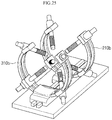
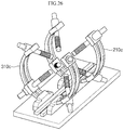
FIGS. 24 to 26 are perspective views showing magnetic field driving systems according to various embodiments of the present disclosure. - According to the present disclosure, a magnetic field drive system includes a rail; a first magnetic field generation unit installed on the rail; and a second magnetic field generation unit installed on the rail while facing the first magnetic field generation unit with a target area interposed therebetween, wherein the first and second magnetic field generation units may generate a magnetic field in the target area.
- Hereinafter, preferable embodiments of the present disclosure will be described in detail with reference to accompanying drawings. However, the spirit and technical scope of the present disclosure is not limited to the embodiments and may be modified variously in many different forms. Rather, the embodiments introduced herein are provided so that the disclosed contents may be thorough and complete, and the spirit of the present disclosure may be sufficiently conveyed to those skilled in the art.
- In the present specification, when it is mentioned that a certain component is on another component, it means that the component may be formed directly on another component or that a third component may be interposed therebetween. In addition, the thicknesses of the lines and the sizes of the components shown in the drawings may be exaggerated for clarity and convenience of explanation.
- In addition, in various embodiments of the present specification, terms, such as "first', "second", "third", and the like, are used to describe various components, but these components should not be limited by the terms. These terms are only used to distinguish one component from another component. Accordingly, what is referred to as a first component in one embodiment may be referred to as a second component in another embodiment. Each embodiment described and illustrated herein also includes its complementary embodiment. In the present disclosure, the term "and/or" indicates at least one of components listed before and after.
- In the present disclosure, the terms of a singular form may include plural forms unless the context clearly indicates otherwise. In addition, terms such as "include" and/or "have" may be construed to denote a certain characteristic, number, step, operation, constituent element, component or a combination thereof, but may not be construed to exclude the existence of or a possibility of addition of one or more other characteristics, numbers, steps, operations, constituent elements, components or combinations thereof. In the present disclosure, "connection" is used to include both indirectly and direct connection of a plurality of components.
- In addition, a detailed description of well-known features or functions will be ruled out in order not to unnecessarily obscure the gist of the present disclosure.
-
FIG. 1 is a perspective view showing a magnetic field generating system according to an embodiment of the present disclosure.FIG. 2 is a front view of the magnetic field generating system ofFIG. 1 ,FIG. 3 is a right-side view of the magnetic field generating system ofFIG. 1 . - Referring to
FIGS. 1 to 3 , the magnetic field generating system generates a magnetic field in a target area. The magneticfield generating system 10 includes arail 100, a first magneticfield generation unit 200, a second magneticfield generation unit 300, adriving unit 400, and apower supply unit 500. - The
rail 100 may have a predetermined length in one direction and be placed on the ground. According to an embodiment, therail 100 may be formed of a magnetic material. - The first and second magnetic
field generation units rail 100, respectively. The first and second magneticfield generation units rail 100. At least an area of the space between the first and second magneticfield generation units field generation units - The first magnetic
field generation unit 200 includes afirst support frame 210, a firstmagnetic core 220, afirst coil 230, and a firstcore variable module 240. - The
first support frame 210 is installed on therail 100. The lower end of thefirst support frame 210 is installed on therail 100. Thefirst support frame 210 may be formed of a magnetic material. Thefirst support frame 210 is provided as a passage through which the magnetic field generated by thefirst coil 230 passes. According to an embodiment, thefirst support frame 210 has a ring shape having a predetermined radius, and its central axis is arranged in parallel with the length direction of therail 100. According to an example, thefirst support frame 210 may be provided with a single frame. Alternatively, thefirst support frame 210 may be provided in a structure in which a pair offrames - The first
magnetic core 220 is supported by thefirst support frame 210 and extends from a predetermined position of thefirst support frame 210 toward the target area T. The firstmagnetic core 220 is a magnetic material having a predetermined shape, and the end is disposed toward the target area T. The firstmagnetic core 220 may have a cylindrical or polygonal column shape. At least one firstmagnetic core 220 may be provided. According to the embodiment, four firstmagnetic cores 220 are provided, and are disposed along the circumference of thefirst support frame 210 while spaced apart from each other by a predetermined interval. Each of the firstmagnetic cores 220 is inclined such that the ends are disposed toward the target area T. - The
first coil 230 is wound around each of the firstmagnetic cores 220. - The first
core variable module 240 is installed on thefirst support frame 210 and moves the firstmagnetic core 220. The firstcore variable module 240 moves the firstmagnetic core 220 along the circumference of thefirst support frame 210. In addition, the firstcore variable module 240 linearly moves the firstmagnetic core 220 in the direction of the central axis of the firstmagnetic core 220. The firstcore variable module 240 is provided to each of the firstmagnetic cores 220 and individually moves the firstmagnetic cores 220. As the firstmagnetic cores 220 move individually along the circumference of thefirst support frame 210, the interval between the firstmagnetic cores 220 may be adjusted. The first corevariable modules 240 may move the firstmagnetic cores 220 such that the intervals between the firstmagnetic cores 220 are the same. Alternatively, the first corevariable modules 240 may move the firstmagnetic cores 220 such that the intervals between the firstmagnetic cores 220 are different from each other. As the firstmagnetic cores 220 move forward or backward in the direction of the central axis by driving of the first corevariable modules 240, the size of the target area T and the intensity of the magnetic field formed in the target area T may be adjusted. In detail, when the firstmagnetic cores 220 move forward, the size of the target area T decreases, and a high-intensity magnetic field may be generated in the target area T. To the contrary, when the firstmagnetic cores 220 move backward, the size of the target area T increases, and a magnetic field having a relatively low intensity may be generated in the target area T. As described above, the size of the target area T and the intensity of the magnetic field formed in the target area T may be adjusted according to the linear movement of the firstmagnetic cores 220. - The second magnetic
field generation unit 300 includes asecond support frame 310, a secondmagnetic core 320, asecond coil 330, and a secondcore variable module 340. - The
second support frame 310 is installed on therail 100. Thesecond support frame 310 has the same shape, material, and size as thefirst support frame 210, and the lower end is placed on therail 100. Thesecond support frame 310 faces thefirst support frame 210, and the central axis is located on the same line as that of thefirst support frame 210. - The second
magnetic core 320 is supported by thesecond support frame 310 and extends from a predetermined position of thesecond support frame 310 toward the target area T. The secondmagnetic core 320 is a magnetic material having the same shape as the firstmagnetic core 220 and the end is disposed toward the target area T. At least one secondmagnetic core 320 may be provided. According to an embodiment, the number of secondmagnetic cores 320 is equal to that of the firstmagnetic cores 220. - The
second coil 330 is wound around the secondmagnetic cores 320, respectively. - The second
core variable module 340 is installed on thesecond support frame 310 and moves the secondmagnetic core 320. The secondcore variable module 340 moves the secondmagnetic core 320 along the circumference of thesecond support frame 310. In addition, the secondcore variable module 340 linearly moves the secondmagnetic core 320 in the direction of the central axis of the secondmagnetic core 320. The secondcore variable module 340 is provided to each of the secondmagnetic cores 320, and individually moves the secondmagnetic cores 320. - The driving
unit 400 moves the first magneticfield generation unit 200 and the second magneticfield generation unit 300 along therail 100. The drivingunit 400 may individually move the first magneticfield generation unit 200 and the second magneticfield generation unit 300. The drivingunit 400 includes afirst driving unit 410 for moving the first magneticfield generation unit 200 and asecond driving unit 420 for moving the second magneticfield generation unit 300. Thefirst driving part 410 is installed on therail 100 and is coupled to thefirst support frame 210. As thefirst driving unit 410 moves along therail 100, thefirst support frame 210 may move. Thesecond driving unit 420 is installed on therail 100 and is coupled to thesecond support frame 310. As thesecond driving unit 420 moves along therail 100, thesecond support frame 310 may move. The position and size of the target area T may be adjusted according to the movements of the first and second support frames 210 and 310. -
FIG. 4 is a diagram (A) showing a connection (A) between a first magnetic field generation unit and a power supply unit according to an embodiment of the present disclosure, and an electrical circuit diagram (B) thereof.FIG. 5 is a diagram (A) showing a connection between a second magnetic field generation unit and a power supply unit according to an exemplary embodiment of the present disclosure, and an electric circuit diagram (B) thereof. - Referring to
FIGS. 4 and 5 , thepower supply unit 500 supplies power to the first andsecond coils power supply unit 500 supplies power to a first circuit connected to thefirst coil 230 and a second circuit connected to thesecond coil 330, respectively. - The first magnetic
field generation unit 200 further includes a firstvariable capacitor 250 provided to the first circuit 201, and the second magneticfield generation unit 300 further includes a secondvariable capacitor 350 provided to the second circuit 301. Accordingly, the first and second circuits 201 and 301 are provided in closed circuits including power sources P1 and P2, resistors R1 and R2, inductances L1 and L2, and capacitances C1 and C2. In this case, the power supplies P1 and P2 refer to thepower supply unit 500, the resistances R1 and R2 and the inductances L1 and L2 refer to the first and secondmagnetic cores second coils variable capacitors - The first and second
variable capacitors variable capacitor - Therefore, by adjusting the capacitance C1 and/or the capacitance C2 of the first
variable capacitor 250 and/or the secondvariable capacitor 350 to cause resonance occurs at a desired frequency, it is possible to generate a magnetic field at a specific frequency (e.g., the frequency of the input voltage). - In this case, the currents flowing through the first and
second coils 
- Where Vs denotes the magnitude of an applied voltage, f denotes the frequency of the applied voltage, Rc and Lc denote the resistance and inductance of a coil, and Cv denotes the capacitance of a variable capacitor. The maximum voltage is obtained at the resonant frequency

-
FIGS. 6 and7 are diagrams showing flows of the magnetic fields generated by first and second magnetic field generation units according to an embodiment of the present disclosure.FIG. 8 is a diagram showing a flow of a magnetic field generated by a magnetic field generator according to a comparative example. - First, referring to
FIGS. 6 and7 , a magnetic field is generated in thefirst coil 230 by power supplied from thepower supply unit 500, and the generated magnetic field flows through the firstmagnetic core 220 and thefirst support frame 210. The magnetic field M1 formed in the firstmagnetic core 220, the magnetic field M2 formed in thefirst support frame 210, and the magnetic field M3 formed in the target area T1 form a closed magnetic circuit. - A magnetic field is generated in the
second coil 330 by power supplied from thepower supply unit 500, and the generated magnetic field flows along the secondmagnetic core 320 and thesecond support frame 310. The magnetic field M1 formed in the secondmagnetic core 320, the magnetic field M2 formed in thesecond support frame 310, and the magnetic field M3 formed in the target area T2 form a closed magnetic circuit. -
FIG. 7 shows that the first and secondmagnetic cores variable modules FIG. 6 , it is possible to generate a high-intensity magnetic field. - In an actual experimental example, in
FIG. 6 , the size of the target area T1 is set to a diameter of 500 mm, and inFIG. 7 , the size of the target area T2 is set to a diameter of 300 mm, where each coil is wound 1,000 times, and a current of 10A is approved thereto. The intensity of the magnetic field at the center point Tc of each of the target area T1 and T2 was 27 mT inFIG. 6 and 70 mT inFIG. 7 . - Unlike the above, the magnetic field generation unit according to
FIG. 8 forms an open magnetic circuit in which the magnetic field generated by thecoil 21 is blocked from flowing in themagnetic cores 22. Like inFIG. 6 , the size of the target area T1 was set to a diameter of 500 mm, and the winding number of a coil and the applied current were the same as above. As a result, the magnetic field intensity at the center point Tc of the target area T1 was 10 mT. - As described above, it may be understood that the closed magnetic circuit has improved magnetic field generation ability than the open magnetic circuit. In particular, it may be confirmed that a high-intensity magnetic field is effectively generated when a target area is formed by fitting a lesion portion.
-
FIG. 9 is a diagram showing a flow of a magnetic field in a magnetic field drive system according to an embodiment of the present disclosure. - Referring to
FIG. 9 , a magnetic field flowing along thefirst support frame 210 may flow to thesecond support frame 320 through therail 100 made of a magnetic material. To the contrary, the magnetic field flowing along thesecond support frame 320 may flow to thefirst support frame 210 through the rail. By such a magnetic field flow, the magnetic fields M1 and M2 formed in the firstmagnetic core 220 and thefirst support frame 210, the magnetic field M3 formed in therail 100, the magnetic fields M4 and M5 formed in the secondmagnetic core 320 and thesecond support frame 310, and the magnetic field Mt formed in the target area T form a closed magnetic circuit. The formation of the closed magnetic circuit maximizes the magnetic field generation ability in the target area (T). -
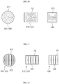
FIG. 10 is a diagram showing each cross section of a magnetic core, a support frame, and a rail according to an embodiment of the present disclosure.FIG. 11 is a diagram showing each cross section of a magnetic core, a support frame, and a rail according to another embodiment of the present disclosure. The cross sections of themagnetic cores FIG. 3 . The cross sections of the support frames 210 and 310 are shown taken along the line B1-B2 ofFIG. 3 . The cross sections of therail 100 are shown taken along line C1-C2 ofFIG. 2 . - First, referring to
FIG. 10 , the first and secondmagnetic cores rail 100 may be formed with a single frame in a solid form. - Differently, referring to
FIG. 11 , the first and secondmagnetic cores rail 100 may be formed by stacking a plurality of third base frames F3. The first to third base frames F1 to F3 are formed of a magnetic material. - The first and second
magnetic cores magnetic cores FIG. 12 , the first and secondmagnetic cores - The second base frames F2 have the same radius as the first and second support frames 210 and 220 and are provided as a ring-shaped plate having a thin thickness, and their central axis is located on the same axis. The second base frames F2 are stacked on each other to constitute the first and second support frames 210 and 220.
- The third base frame F3 constitutes the
rail 100 by stacking thin plates having the same length in the width direction of therail 100. - When a high-power high-frequency magnetic field is generated, eddy currents EC1 and EC2 flow through the first and second
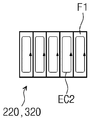
magnetic cores rail 100. Such eddy currents may be a factor that decreases the intensity of the high-frequency magnetic field. - In the embodiment of
FIG. 10 , because the first and secondmagnetic cores rail 100 have relatively large cross-sectional areas, the area through which the eddy current can flow increases, so that the intensity of the eddy current EC1 increases. - To the contrary, in the embodiments of
FIGS. 11 and12 , the first and secondmagnetic cores rail 100 generate the eddy currents EC2 inside base frames F1, F2 and F3, respectively. Compared with the embodiment ofFIG. 10 , since each of the base frames F1, F2, and F3 has a relatively small cross-sectional area, an area through which the eddy current EC2 can flow is reduced. Accordingly, the intensity of the eddy currents EC2 flowing inside the base frames F1, F2 and F3 may be reduced, and an effect of reducing the magnetic field intensity due to the eddy current may be reduced. -
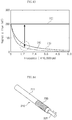
FIG. 13 is a graph showing the results of analytically calculating the intensity of a magnetic field that may be generated when a high-frequency magnetic field is generated according to the application of a variable capacitor and a stacked magnetic structure. A first graph A shows the intensity of the magnetic field according to an embodiment in which a variable capacitor and a stacked magnetic structure are not applied, A second graph B shows the intensity of a magnetic field according to an embodiment in which a variable capacitor is applied and a stacked magnetic structure is not applied, as shown inFIG. 10 . A third graph C shows the intensity of a magnetic field according to an embodiment in which both a variable capacitor and a stacked magnetic structure are applied as shown inFIG. 11 . - Referring to
FIG. 13 , the resistance of the magnetic field generation unit is set to about 8 Ω and the inductance is set to about 0.8 H, and the current intensity is applied to generate a magnetic field of about an intensity of 200 mT in the target area. Comparing the results according to the respective embodiments, it may be understood that the difference in the intensity of the magnetic field which is able to be generated increases rapidly as the frequency of the magnetic field increases. Accordingly, it may be understood that a variable capacitor and a stacked magnetic structure are essential in order to generate a high-power high-frequency magnetic field. -
FIG. 14 is a view showing the first and second magnetic cores according to another embodiment of the present disclosure.FIG. 15 is a front view showing the first and second magnetic cores ofFIG. 14 . The first and second magnetic cores may be provided in the same structure. An example of the first magnetic core will be described below. - Referring to
FIGS. 14 and15 , the firstmagnetic core 220 includes afirst core housing 211, a firstauxiliary core 213, and a first core driving unit (not shown). - The
first core housing 211 has afirst coil 230 wound on an outer surface thereof, and a space is formed therein. Anopening 211a is formed at one end of thefirst core housing 211. Theopening 211a communicates with the inside of thefirst core housing 211. - The first
auxiliary core 213 has a volume smaller than that of thefirst core housing 211 and is inserted into thefirst core housing 211 through theopening 211a. The firstauxiliary core 213 is formed of a magnetic material. According to an embodiment, the firstauxiliary core 213 may have a column shape having a diameter corresponding to theopening 211a. The central axis C of the firstauxiliary core 213 may be positioned on the same lien as the central axis C of thefirst core housing 211. - The first core driving unit linearly moves the first
auxiliary core 213 in the direction of the central axis C. Accordingly, the front end of the firstauxiliary core 213 may be located at the same point as one end of thefirst core housing 211 or may protrude forward of thefirst core housing 211. - The magnetic field generated by the
first coil 230 flows along thefirst core housing 211 and the firstauxiliary core 213 to generate a magnetic field in the target area T. The location of the end of the firstmagnetic core 210 may be changed according to the linear movement of the firstauxiliary core 213, and accordingly, the intensity and distribution of the magnetic field that can be generated may be variously adjusted. In addition, by moving the firstauxiliary core 213 having a relatively small weight, it is possible to minimize the occurrence of a load according to the movement. -
FIG. 16 is a perspective view showing a first magnetic core according to still another embodiment of the present disclosure.FIG. 17 is a front view showing the first magnetic core ofFIG. 16 . - Referring to
FIGS. 16 and17 , the firstauxiliary core 213 has a central axis C1 spaced apart from the central axis C of thefirst core housing 211 by a predetermined distance, so that the central axis C1 of the firstauxiliary core 213 is arranged parallel to the central axis C of thefirst core housing 211. The firstauxiliary core 213 is linearly moved in the direction of the central axis C1 by the first core driving unit. -
FIG. 18 is a perspective view showing a first magnetic core according to still another embodiment of the present disclosure.FIG. 19 is a front view showing the first magnetic core ofFIG. 18 . - Referring to
FIGS. 18 and 19 , a plurality ofopenings first core housing 211. Theopenings openings openings first core housing 211, and each of theopenings - The first
auxiliary cores 213 are inserted into theopenings auxiliary cores 213 have diameters corresponding to the insertedopenings auxiliary cores 213 are spaced apart from the central axis C of thefirst core housing 211 by a predetermined distance, so that the first central axes C1 and C2 are arranged parallel to the central axis C of thefirst core housing 211. - The first core drive unit linearly moves the first
auxiliary cores 213 individually in the direction of their central axes C1 and C2. Accordingly, the lengths of the firstauxiliary cores 213 protruding in front of thefirst core housing 211 may be adjusted. -
FIGS. 20 to 23 are views sequentially illustrating a method of driving a magnetic field drive system according to an embodiment of the present disclosure. - Referring to
FIGS. 20 to 23 , a method of driving the magneticfield drive system 10 first places a patient 20 on abed 30. In addition, the positions of the first and second magneticfield generation units patient 20 is located in the target area of the magneticfield drive system 10. In the present embodiment, the head region of thepatient 20 is located in the target area for the treatment of brain disease of thepatient 20. By driving of the first andsecond driving units field generation units rail 100 to cause a lesion portion of the patient 20 to located in the target area. The first and second corevariable modules magnetic cores magnetic cores x-ray imaging apparatus 40 is positioned, power is applied to the first andsecond coils patient 20 is tracked based on the perspective image obtained by thex-ray imaging apparatus 40, and the movement of the magnetic robot moves may be controlled by using the magnetic field generated by the magneticfield drive system 10. As described above, the intensity of the magnetic field generated in the target area may be increased by the formation of the closed magnetic circuit. -
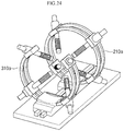
FIGS. 24 to 26 are perspective views showing magnetic field driving systems according to various embodiments of the present disclosure. - Referring to
FIGS. 24 to 26 , the first and second support frames of the magnetic field drive system may have a ring or arc shape. Referring toFIG. 24 , thefirst support frame 210a may have a ring shape, and thesecond support frame 310a may have an arc shape having an open top. Referring toFIG. 25 , both of the first and second support frames 210b and 310b may have an arc shape having an open top. Referring toFIG. 26 , both of the first and second support frames 210c and 310c may have an arc shape in which upper and lower portions are open. The combination of the first and second support frames is not limited thereto, and may be changed to various combinations of the above-described ring and arc shapes. - The shapes of the first and second support frames 210a to 210c and 310a to 310c described above maximize compatibility between an x-ray imaging apparatus including a C-arm and a magnetic field drive system. In addition, the first and second support frames 210a to 210c and 310a to 310c are lightened in weight.
- As described above, although the present disclosure has been described in detail using preferred embodiments, the scope of the present disclosure is not limited to specific embodiments, and should be interpreted by the appended claims. In addition, it should be understood that various modifications and alterations can be made from the disclosures above by a person having ordinary skill in the art, without departing from the scope of the present disclosure.
- The magnetic field drive system according to the present disclosure may drive a magnetic robot by generating a magnetic field in a target area.
Claims (18)
- A magnetic field drive system comprising:a rail;a first magnetic field generation unit installed on the rail; anda second magnetic field generation unit installed on the rail while facing the first magnetic field generation unit with a target area interposed therebetween,wherein the first and second magnetic field generation units generate a magnetic field in the target area.
- The magnetic field drive system of claim 1, further comprising:
a driving unit configured to move the first and second magnetic field generation units along the rail. - The magnetic field drive system of claim 1, wherein the first magnetic field generation unit includesa first support frame installed on the rail;at least one first magnetic core supported by the first support frame and having ends disposed toward the target area; anda first coil wound around each of the first magnetic cores,wherein the second magnetic field generation unit includesa second support frame installed on the rail while facing the first support frame;at least one second magnetic core supported by the second support frame and having ends disposed toward the target area; anda second coil wound around each of the second magnetic cores.
- The magnetic field drive system of claim 3, wherein the first magnetic field generation unit includes a first core variable module configured to move the first magnetic core along the first support frame, and
wherein the second magnetic field generation unit includes a second core variable module configured to move the second magnetic core along the second support frame. - The magnetic field drive system of claim 4, wherein the first core variable module is configured to individually move the first magnetic cores, and
the second core variable module is configured to individually move the second magnetic cores. - The magnetic field drive system of claim 4, wherein the first core variable module is configured to linearly move the first magnetic core in a direction of a central axis of the first magnetic core, and
the second core variable module is configured to linearly move the second magnetic core in a direction of a central axis of the second magnetic core. - The magnetic field drive system of claim 4, wherein the first and second support frames have ring or arc shapes, respectively, and centers thereof are located on a same axis.
- The magnetic field drive system of claim 3, wherein the first and second magnetic cores, the first and second support frames and the rail are formed of a magnetic material, and
the magnetic field formed in the target area, and magnetic fields formed in the first magnetic core, the first support frame, the rail, the second support frame and the second magnetic core, respectively, constitute a closed magnetic circuit. - The magnetic field drive system of claim 3, further comprising:a power supply unit configured to supply power to the first coil through a first circuit and supply power to the second coil through a second circuit; andvariable capacitors provided in the first circuit and the second circuit, respectively.
- The magnetic field drive system of claim 3, wherein the first support frame has a structure in which a plurality of base frames formed of a magnetic material are stacked.
- The magnetic field drive system of claim 10, wherein the base frames have a same radius as the first support frame, and are located on a same central axis.
- The magnetic field drive system of claim 3, wherein the first magnetic core has a structure in which a plurality of base frames formed of a magnetic material are stacked, and
the base frames have a same length as the first magnetic core. - The magnetic field drive system of claim 3, wherein the rail has a structure in which a plurality of base frames formed of a magnetic material are stacked, and
the base frames have a same length as the rail. - The magnetic field drive system of claim 3, wherein the first magnetic core includes:a first core housing having an outer side surface around which the first coil is wound, an inner space, and one end in which an opening is formed;a first auxiliary core inserted into the inner space through the opening; anda first core driving unit configured to linearly move the first auxiliary core in a central direction thereof.
- The magnetic field drive system of claim 14, wherein a central axis of the first core housing and a central axis of the first auxiliary core are located on a same line.
- The magnetic field drive system of claim 14, wherein the central axis of the first core housing is parallel with the central axis of the first auxiliary core.
- The magnetic field drive system of claim 14, wherein a plurality of openings are formed at one end of the first core housing,a plurality of first auxiliary cores are inserted into the openings, respectively, andthe first core driving unit is configured to individually move the first auxiliary cores.
- The magnetic field drive system of claim 17, wherein the openings have mutually different sizes, and
the first auxiliary cores have sizes corresponding to the openings, respectively.
Applications Claiming Priority (3)
| Application Number | Priority Date | Filing Date | Title |
|---|---|---|---|
| KR20180150004 | 2018-11-28 | ||
| KR1020190026745A KR102256332B1 (en) | 2018-11-28 | 2019-03-08 | Magnetic navigation system |
| PCT/KR2019/014660 WO2020111539A1 (en) | 2018-11-28 | 2019-11-01 | Magnetic field drive system |
Publications (3)
| Publication Number | Publication Date |
|---|---|
| EP3888581A1 true EP3888581A1 (en) | 2021-10-06 |
| EP3888581A4 EP3888581A4 (en) | 2022-08-17 |
| EP3888581B1 EP3888581B1 (en) | 2024-12-04 |
Family
ID=71089279
Family Applications (1)
| Application Number | Title | Priority Date | Filing Date |
|---|---|---|---|
| EP19889185.5A Active EP3888581B1 (en) | 2018-11-28 | 2019-11-01 | Magnetic field drive system |
Country Status (4)
| Country | Link |
|---|---|
| US (1) | US12014869B2 (en) |
| EP (1) | EP3888581B1 (en) |
| KR (1) | KR102256332B1 (en) |
| CN (1) | CN113056237B (en) |
Families Citing this family (7)
| Publication number | Priority date | Publication date | Assignee | Title |
|---|---|---|---|---|
| EP3499529A4 (en) * | 2016-08-10 | 2020-04-29 | IUCF-HYU (Industry-University Cooperation Foundation Hanyang University) | Magnetic field control system |
| EP4005519B1 (en) | 2019-07-26 | 2025-09-10 | Iucf-Hyu (Industry-University Cooperation Foundation Hanyang University) | Magnetic drive system for controlling movements of a microrobot |
| KR102421465B1 (en) * | 2020-07-03 | 2022-07-18 | 한양대학교 산학협력단 | Magnetic navigation system |
| CN112959311B (en) * | 2021-02-24 | 2023-11-07 | 哈尔滨工业大学 | High-frequency strong magnetic field generation device and magnetic field control method based on multi-stage electromagnets |
| KR102548278B1 (en) * | 2021-06-14 | 2023-06-28 | 재단법인 한국마이크로의료로봇연구원 | Movable integrated system for actuating and recognizing position of magnetic body |
| KR20250030079A (en) * | 2023-08-24 | 2025-03-05 | 재단법인대구경북과학기술원 | Magnetic actuation system |
| US20250100129A1 (en) * | 2023-09-27 | 2025-03-27 | Purdue Research Foundation | Microrobot control system and method |
Family Cites Families (17)
| Publication number | Priority date | Publication date | Assignee | Title |
|---|---|---|---|---|
| US6459924B1 (en) * | 1997-11-12 | 2002-10-01 | Stereotaxis, Inc. | Articulated magnetic guidance systems and devices and methods for using same for magnetically-assisted surgery |
| US6330467B1 (en) * | 1999-02-04 | 2001-12-11 | Stereotaxis, Inc. | Efficient magnet system for magnetically-assisted surgery |
| US6702804B1 (en) * | 1999-10-04 | 2004-03-09 | Stereotaxis, Inc. | Method for safely and efficiently navigating magnetic devices in the body |
| KR100615881B1 (en) * | 2004-06-21 | 2006-08-25 | 한국과학기술연구원 | Capsule Endoscope Control System |
| US20070244388A1 (en) * | 2004-12-17 | 2007-10-18 | Ryoji Sato | Position Detection System, Guidance System, Position Detection Method, Medical Device, and Medical Magnetic-Induction and Position-Detection System |
| US8027714B2 (en) * | 2005-05-27 | 2011-09-27 | Magnetecs, Inc. | Apparatus and method for shaped magnetic field control for catheter, guidance, control, and imaging |
| CN101719714B (en) * | 2009-11-05 | 2011-12-21 | 江苏大学 | Eddy current retarder of magnetic track of railway vehicle |
| WO2011072060A2 (en) * | 2009-12-08 | 2011-06-16 | Magnetecs Corporation | Diagnostic and therapeutic magnetic propulsion capsule and method for using the same |
| US20130303878A1 (en) * | 2011-01-20 | 2013-11-14 | Enav Medical Ltd. | System and method to estimate location and orientation of an object |
| CN203733601U (en) * | 2014-03-25 | 2014-07-23 | 哈尔滨理工大学 | Double-magnetic-core adjustable reactor |
| CN105816174A (en) * | 2015-01-08 | 2016-08-03 | 西门子(深圳)磁共振有限公司 | Magnetic resonance device |
| KR101647020B1 (en) * | 2015-03-12 | 2016-08-11 | 전남대학교산학협력단 | Electromagnetic based actuation device with adjustable movement of coil-module |
| JP2017000354A (en) * | 2015-06-09 | 2017-01-05 | セイコーエプソン株式会社 | Magnetic field measurement device and magnetic field measurement method |
| KR101740553B1 (en) | 2016-03-14 | 2017-05-26 | 재단법인대구경북과학기술원 | Magnetic field precise control system with x-ray apparatus |
| US12020861B2 (en) * | 2016-05-26 | 2024-06-25 | The Trustees Of The University Of Pennsylvania | Laminated magnetic cores |
| KR101765015B1 (en) * | 2016-09-30 | 2017-08-10 | 한양대학교 산학협력단 | Apparatus for generating magnetic field |
| CN206991865U (en) * | 2017-04-05 | 2018-02-09 | 湖南城市学院 | A kind of adjustable magnetic field intensity and the field generator for magnetic in direction |
-
2019
- 2019-03-08 KR KR1020190026745A patent/KR102256332B1/en active Active
- 2019-11-01 CN CN201980076124.9A patent/CN113056237B/en active Active
- 2019-11-01 US US17/298,220 patent/US12014869B2/en active Active
- 2019-11-01 EP EP19889185.5A patent/EP3888581B1/en active Active
Also Published As
| Publication number | Publication date |
|---|---|
| CN113056237A (en) | 2021-06-29 |
| KR20200063942A (en) | 2020-06-05 |
| CN113056237B (en) | 2024-05-28 |
| EP3888581B1 (en) | 2024-12-04 |
| EP3888581A4 (en) | 2022-08-17 |
| KR102256332B1 (en) | 2021-05-26 |
| US20220122752A1 (en) | 2022-04-21 |
| US12014869B2 (en) | 2024-06-18 |
Similar Documents
| Publication | Publication Date | Title |
|---|---|---|
| EP3888581B1 (en) | Magnetic field drive system | |
| US11957848B2 (en) | Magnetically controlled medical devices for interventional medical procedures and methods of making and controlling the same | |
| US11890487B2 (en) | Method and apparatus for multi-channel simultaneously high power magnetic coil driver | |
| KR101647020B1 (en) | Electromagnetic based actuation device with adjustable movement of coil-module | |
| KR102665851B1 (en) | Apparatus for controlling magnetic field | |
| US12478446B2 (en) | Magnetic drive system and microrobot control method | |
| WO2001037926A1 (en) | Apparatus for transferring energy across a boundary | |
| KR102436113B1 (en) | Magnetic field generator for precision procedure | |
| EP3325091B1 (en) | Focused power transfer for implantable medical device | |
| EP2105163B1 (en) | Varying magnetic field application device for heating magnetic or magnetisable substances in biological tissue | |
| WO2020111539A1 (en) | Magnetic field drive system | |
| KR102407223B1 (en) | Nano particle control apparatus | |
| KR102314636B1 (en) | Electromagnetic drive system for micro robot | |
| KR102421465B1 (en) | Magnetic navigation system | |
| EP4360532A1 (en) | Magnetic field generation module and magnetic field generation device comprising same | |
| KR102260162B1 (en) | Apparatus for Controlling Micro Robot | |
| CN112439123B (en) | Nano robot control system | |
| Qin et al. | Design and Control of a Dual‐Coil Magnetic Guidewire for Smooth and Adaptive Curvature Steering in Vascular Intervention | |
| CN115814278B (en) | Magnetic stimulation coil assembly and medical magnetic stimulation equipment | |
| CN110127771B (en) | Controlled Aggregation of Ferrous Oxide Nanoparticles | |
| EP1170032B1 (en) | Magnetic field generator for an electromedical treatment apparatus | |
| CN222565938U (en) | Three-dimensional interventional instrument electromagnetic generating equipment and electromagnetic navigation control system | |
| CN112438835A (en) | Control device and control system of nano robot | |
| KR20250030079A (en) | Magnetic actuation system | |
| WO2002004072A1 (en) | Magnetic generator for an electromedical treatment apparatus |
Legal Events
| Date | Code | Title | Description |
|---|---|---|---|
| STAA | Information on the status of an ep patent application or granted ep patent |
Free format text: STATUS: THE INTERNATIONAL PUBLICATION HAS BEEN MADE |
|
| PUAI | Public reference made under article 153(3) epc to a published international application that has entered the european phase |
Free format text: ORIGINAL CODE: 0009012 |
|
| STAA | Information on the status of an ep patent application or granted ep patent |
Free format text: STATUS: REQUEST FOR EXAMINATION WAS MADE |
|
| 17P | Request for examination filed |
Effective date: 20210625 |
|
| AK | Designated contracting states |
Kind code of ref document: A1 Designated state(s): AL AT BE BG CH CY CZ DE DK EE ES FI FR GB GR HR HU IE IS IT LI LT LU LV MC MK MT NL NO PL PT RO RS SE SI SK SM TR |
|
| DAV | Request for validation of the european patent (deleted) | ||
| DAX | Request for extension of the european patent (deleted) | ||
| A4 | Supplementary search report drawn up and despatched |
Effective date: 20220720 |
|
| RIC1 | Information provided on ipc code assigned before grant |
Ipc: A61B 17/00 20060101ALI20220714BHEP Ipc: A61B 34/30 20160101ALI20220714BHEP Ipc: A61B 17/22 20060101ALI20220714BHEP Ipc: A61B 34/35 20160101ALI20220714BHEP Ipc: A61B 34/00 20160101AFI20220714BHEP |
|
| GRAP | Despatch of communication of intention to grant a patent |
Free format text: ORIGINAL CODE: EPIDOSNIGR1 |
|
| STAA | Information on the status of an ep patent application or granted ep patent |
Free format text: STATUS: GRANT OF PATENT IS INTENDED |
|
| INTG | Intention to grant announced |
Effective date: 20240705 |
|
| GRAS | Grant fee paid |
Free format text: ORIGINAL CODE: EPIDOSNIGR3 |
|
| GRAA | (expected) grant |
Free format text: ORIGINAL CODE: 0009210 |
|
| STAA | Information on the status of an ep patent application or granted ep patent |
Free format text: STATUS: THE PATENT HAS BEEN GRANTED |
|
| AK | Designated contracting states |
Kind code of ref document: B1 Designated state(s): AL AT BE BG CH CY CZ DE DK EE ES FI FR GB GR HR HU IE IS IT LI LT LU LV MC MK MT NL NO PL PT RO RS SE SI SK SM TR |
|
| REG | Reference to a national code |
Ref country code: CH Ref legal event code: EP |
|
| REG | Reference to a national code |
Ref country code: DE Ref legal event code: R096 Ref document number: 602019063193 Country of ref document: DE |
|
| REG | Reference to a national code |
Ref country code: IE Ref legal event code: FG4D |
|
| REG | Reference to a national code |
Ref country code: LT Ref legal event code: MG9D |
|
| REG | Reference to a national code |
Ref country code: NL Ref legal event code: MP Effective date: 20241204 |
|
| PG25 | Lapsed in a contracting state [announced via postgrant information from national office to epo] |
Ref country code: HR Free format text: LAPSE BECAUSE OF FAILURE TO SUBMIT A TRANSLATION OF THE DESCRIPTION OR TO PAY THE FEE WITHIN THE PRESCRIBED TIME-LIMIT Effective date: 20241204 |
|
| PG25 | Lapsed in a contracting state [announced via postgrant information from national office to epo] |
Ref country code: FI Free format text: LAPSE BECAUSE OF FAILURE TO SUBMIT A TRANSLATION OF THE DESCRIPTION OR TO PAY THE FEE WITHIN THE PRESCRIBED TIME-LIMIT Effective date: 20241204 |
|
| PG25 | Lapsed in a contracting state [announced via postgrant information from national office to epo] |
Ref country code: BG Free format text: LAPSE BECAUSE OF FAILURE TO SUBMIT A TRANSLATION OF THE DESCRIPTION OR TO PAY THE FEE WITHIN THE PRESCRIBED TIME-LIMIT Effective date: 20241204 |
|
| PG25 | Lapsed in a contracting state [announced via postgrant information from national office to epo] |
Ref country code: ES Free format text: LAPSE BECAUSE OF FAILURE TO SUBMIT A TRANSLATION OF THE DESCRIPTION OR TO PAY THE FEE WITHIN THE PRESCRIBED TIME-LIMIT Effective date: 20241204 |
|
| PG25 | Lapsed in a contracting state [announced via postgrant information from national office to epo] |
Ref country code: NO Free format text: LAPSE BECAUSE OF FAILURE TO SUBMIT A TRANSLATION OF THE DESCRIPTION OR TO PAY THE FEE WITHIN THE PRESCRIBED TIME-LIMIT Effective date: 20250304 |
|
| PG25 | Lapsed in a contracting state [announced via postgrant information from national office to epo] |
Ref country code: LV Free format text: LAPSE BECAUSE OF FAILURE TO SUBMIT A TRANSLATION OF THE DESCRIPTION OR TO PAY THE FEE WITHIN THE PRESCRIBED TIME-LIMIT Effective date: 20241204 Ref country code: GR Free format text: LAPSE BECAUSE OF FAILURE TO SUBMIT A TRANSLATION OF THE DESCRIPTION OR TO PAY THE FEE WITHIN THE PRESCRIBED TIME-LIMIT Effective date: 20250305 |
|
| PG25 | Lapsed in a contracting state [announced via postgrant information from national office to epo] |
Ref country code: RS Free format text: LAPSE BECAUSE OF FAILURE TO SUBMIT A TRANSLATION OF THE DESCRIPTION OR TO PAY THE FEE WITHIN THE PRESCRIBED TIME-LIMIT Effective date: 20250304 |
|
| PG25 | Lapsed in a contracting state [announced via postgrant information from national office to epo] |
Ref country code: NL Free format text: LAPSE BECAUSE OF FAILURE TO SUBMIT A TRANSLATION OF THE DESCRIPTION OR TO PAY THE FEE WITHIN THE PRESCRIBED TIME-LIMIT Effective date: 20241204 |
|
| REG | Reference to a national code |
Ref country code: AT Ref legal event code: MK05 Ref document number: 1747296 Country of ref document: AT Kind code of ref document: T Effective date: 20241204 |
|
| PG25 | Lapsed in a contracting state [announced via postgrant information from national office to epo] |
Ref country code: SM Free format text: LAPSE BECAUSE OF FAILURE TO SUBMIT A TRANSLATION OF THE DESCRIPTION OR TO PAY THE FEE WITHIN THE PRESCRIBED TIME-LIMIT Effective date: 20241204 |
|
| PG25 | Lapsed in a contracting state [announced via postgrant information from national office to epo] |
Ref country code: PL Free format text: LAPSE BECAUSE OF FAILURE TO SUBMIT A TRANSLATION OF THE DESCRIPTION OR TO PAY THE FEE WITHIN THE PRESCRIBED TIME-LIMIT Effective date: 20241204 |
|
| PG25 | Lapsed in a contracting state [announced via postgrant information from national office to epo] |
Ref country code: IS Free format text: LAPSE BECAUSE OF FAILURE TO SUBMIT A TRANSLATION OF THE DESCRIPTION OR TO PAY THE FEE WITHIN THE PRESCRIBED TIME-LIMIT Effective date: 20250404 |
|
| PG25 | Lapsed in a contracting state [announced via postgrant information from national office to epo] |
Ref country code: PT Free format text: LAPSE BECAUSE OF FAILURE TO SUBMIT A TRANSLATION OF THE DESCRIPTION OR TO PAY THE FEE WITHIN THE PRESCRIBED TIME-LIMIT Effective date: 20250404 |
|
| PG25 | Lapsed in a contracting state [announced via postgrant information from national office to epo] |
Ref country code: EE Free format text: LAPSE BECAUSE OF FAILURE TO SUBMIT A TRANSLATION OF THE DESCRIPTION OR TO PAY THE FEE WITHIN THE PRESCRIBED TIME-LIMIT Effective date: 20241204 |
|
| PG25 | Lapsed in a contracting state [announced via postgrant information from national office to epo] |
Ref country code: AT Free format text: LAPSE BECAUSE OF FAILURE TO SUBMIT A TRANSLATION OF THE DESCRIPTION OR TO PAY THE FEE WITHIN THE PRESCRIBED TIME-LIMIT Effective date: 20241204 Ref country code: RO Free format text: LAPSE BECAUSE OF FAILURE TO SUBMIT A TRANSLATION OF THE DESCRIPTION OR TO PAY THE FEE WITHIN THE PRESCRIBED TIME-LIMIT Effective date: 20241204 |
|
| PG25 | Lapsed in a contracting state [announced via postgrant information from national office to epo] |
Ref country code: SK Free format text: LAPSE BECAUSE OF FAILURE TO SUBMIT A TRANSLATION OF THE DESCRIPTION OR TO PAY THE FEE WITHIN THE PRESCRIBED TIME-LIMIT Effective date: 20241204 |
|
| PG25 | Lapsed in a contracting state [announced via postgrant information from national office to epo] |
Ref country code: CZ Free format text: LAPSE BECAUSE OF FAILURE TO SUBMIT A TRANSLATION OF THE DESCRIPTION OR TO PAY THE FEE WITHIN THE PRESCRIBED TIME-LIMIT Effective date: 20241204 |
|
| PG25 | Lapsed in a contracting state [announced via postgrant information from national office to epo] |
Ref country code: IT Free format text: LAPSE BECAUSE OF FAILURE TO SUBMIT A TRANSLATION OF THE DESCRIPTION OR TO PAY THE FEE WITHIN THE PRESCRIBED TIME-LIMIT Effective date: 20241204 |
|
| REG | Reference to a national code |
Ref country code: DE Ref legal event code: R097 Ref document number: 602019063193 Country of ref document: DE |
|
| PG25 | Lapsed in a contracting state [announced via postgrant information from national office to epo] |
Ref country code: SE Free format text: LAPSE BECAUSE OF FAILURE TO SUBMIT A TRANSLATION OF THE DESCRIPTION OR TO PAY THE FEE WITHIN THE PRESCRIBED TIME-LIMIT Effective date: 20241204 |
|
| PG25 | Lapsed in a contracting state [announced via postgrant information from national office to epo] |
Ref country code: DK Free format text: LAPSE BECAUSE OF FAILURE TO SUBMIT A TRANSLATION OF THE DESCRIPTION OR TO PAY THE FEE WITHIN THE PRESCRIBED TIME-LIMIT Effective date: 20241204 |
|
| PLBE | No opposition filed within time limit |
Free format text: ORIGINAL CODE: 0009261 |
|
| STAA | Information on the status of an ep patent application or granted ep patent |
Free format text: STATUS: NO OPPOSITION FILED WITHIN TIME LIMIT |
|
| REG | Reference to a national code |
Ref country code: CH Ref legal event code: L10 Free format text: ST27 STATUS EVENT CODE: U-0-0-L10-L00 (AS PROVIDED BY THE NATIONAL OFFICE) Effective date: 20251015 |
|
| PGFP | Annual fee paid to national office [announced via postgrant information from national office to epo] |
Ref country code: GB Payment date: 20250922 Year of fee payment: 7 |
|
| PGFP | Annual fee paid to national office [announced via postgrant information from national office to epo] |
Ref country code: FR Payment date: 20250925 Year of fee payment: 7 |
|
| 26N | No opposition filed |
Effective date: 20250905 |
|
| REG | Reference to a national code |
Ref country code: CH Ref legal event code: U11 Free format text: ST27 STATUS EVENT CODE: U-0-0-U10-U11 (AS PROVIDED BY THE NATIONAL OFFICE) Effective date: 20251201 |
|
| PGFP | Annual fee paid to national office [announced via postgrant information from national office to epo] |
Ref country code: DE Payment date: 20250922 Year of fee payment: 7 |
|
| PGFP | Annual fee paid to national office [announced via postgrant information from national office to epo] |
Ref country code: CH Payment date: 20251201 Year of fee payment: 7 |