EP3888488A1 - Printer - Google Patents
Printer Download PDFInfo
- Publication number
- EP3888488A1 EP3888488A1 EP19888787.9A EP19888787A EP3888488A1 EP 3888488 A1 EP3888488 A1 EP 3888488A1 EP 19888787 A EP19888787 A EP 19888787A EP 3888488 A1 EP3888488 A1 EP 3888488A1
- Authority
- EP
- European Patent Office
- Prior art keywords
- head
- nozzle cap
- nozzle
- cap
- printer
- Prior art date
- Legal status (The legal status is an assumption and is not a legal conclusion. Google has not performed a legal analysis and makes no representation as to the accuracy of the status listed.)
- Granted
Links
Images






Classifications
-
- B—PERFORMING OPERATIONS; TRANSPORTING
- B41—PRINTING; LINING MACHINES; TYPEWRITERS; STAMPS
- B41J—TYPEWRITERS; SELECTIVE PRINTING MECHANISMS, i.e. MECHANISMS PRINTING OTHERWISE THAN FROM A FORME; CORRECTION OF TYPOGRAPHICAL ERRORS
- B41J2/00—Typewriters or selective printing mechanisms characterised by the printing or marking process for which they are designed
- B41J2/005—Typewriters or selective printing mechanisms characterised by the printing or marking process for which they are designed characterised by bringing liquid or particles selectively into contact with a printing material
- B41J2/01—Ink jet
- B41J2/135—Nozzles
- B41J2/165—Prevention or detection of nozzle clogging, e.g. cleaning, capping or moistening for nozzles
- B41J2/16517—Cleaning of print head nozzles
- B41J2/16535—Cleaning of print head nozzles using wiping constructions
- B41J2/16544—Constructions for the positioning of wipers
-
- B—PERFORMING OPERATIONS; TRANSPORTING
- B41—PRINTING; LINING MACHINES; TYPEWRITERS; STAMPS
- B41J—TYPEWRITERS; SELECTIVE PRINTING MECHANISMS, i.e. MECHANISMS PRINTING OTHERWISE THAN FROM A FORME; CORRECTION OF TYPOGRAPHICAL ERRORS
- B41J2/00—Typewriters or selective printing mechanisms characterised by the printing or marking process for which they are designed
- B41J2/005—Typewriters or selective printing mechanisms characterised by the printing or marking process for which they are designed characterised by bringing liquid or particles selectively into contact with a printing material
- B41J2/01—Ink jet
-
- B—PERFORMING OPERATIONS; TRANSPORTING
- B41—PRINTING; LINING MACHINES; TYPEWRITERS; STAMPS
- B41J—TYPEWRITERS; SELECTIVE PRINTING MECHANISMS, i.e. MECHANISMS PRINTING OTHERWISE THAN FROM A FORME; CORRECTION OF TYPOGRAPHICAL ERRORS
- B41J2/00—Typewriters or selective printing mechanisms characterised by the printing or marking process for which they are designed
- B41J2/005—Typewriters or selective printing mechanisms characterised by the printing or marking process for which they are designed characterised by bringing liquid or particles selectively into contact with a printing material
- B41J2/01—Ink jet
- B41J2/135—Nozzles
- B41J2/165—Prevention or detection of nozzle clogging, e.g. cleaning, capping or moistening for nozzles
-
- B—PERFORMING OPERATIONS; TRANSPORTING
- B41—PRINTING; LINING MACHINES; TYPEWRITERS; STAMPS
- B41J—TYPEWRITERS; SELECTIVE PRINTING MECHANISMS, i.e. MECHANISMS PRINTING OTHERWISE THAN FROM A FORME; CORRECTION OF TYPOGRAPHICAL ERRORS
- B41J2/00—Typewriters or selective printing mechanisms characterised by the printing or marking process for which they are designed
- B41J2/005—Typewriters or selective printing mechanisms characterised by the printing or marking process for which they are designed characterised by bringing liquid or particles selectively into contact with a printing material
- B41J2/01—Ink jet
- B41J2/135—Nozzles
- B41J2/165—Prevention or detection of nozzle clogging, e.g. cleaning, capping or moistening for nozzles
- B41J2/16505—Caps, spittoons or covers for cleaning or preventing drying out
- B41J2/16508—Caps, spittoons or covers for cleaning or preventing drying out connected with the printer frame
-
- B—PERFORMING OPERATIONS; TRANSPORTING
- B41—PRINTING; LINING MACHINES; TYPEWRITERS; STAMPS
- B41J—TYPEWRITERS; SELECTIVE PRINTING MECHANISMS, i.e. MECHANISMS PRINTING OTHERWISE THAN FROM A FORME; CORRECTION OF TYPOGRAPHICAL ERRORS
- B41J2/00—Typewriters or selective printing mechanisms characterised by the printing or marking process for which they are designed
- B41J2/005—Typewriters or selective printing mechanisms characterised by the printing or marking process for which they are designed characterised by bringing liquid or particles selectively into contact with a printing material
- B41J2/01—Ink jet
- B41J2/135—Nozzles
- B41J2/165—Prevention or detection of nozzle clogging, e.g. cleaning, capping or moistening for nozzles
- B41J2/16505—Caps, spittoons or covers for cleaning or preventing drying out
- B41J2/16508—Caps, spittoons or covers for cleaning or preventing drying out connected with the printer frame
- B41J2/16511—Constructions for cap positioning
-
- B—PERFORMING OPERATIONS; TRANSPORTING
- B41—PRINTING; LINING MACHINES; TYPEWRITERS; STAMPS
- B41J—TYPEWRITERS; SELECTIVE PRINTING MECHANISMS, i.e. MECHANISMS PRINTING OTHERWISE THAN FROM A FORME; CORRECTION OF TYPOGRAPHICAL ERRORS
- B41J2/00—Typewriters or selective printing mechanisms characterised by the printing or marking process for which they are designed
- B41J2/005—Typewriters or selective printing mechanisms characterised by the printing or marking process for which they are designed characterised by bringing liquid or particles selectively into contact with a printing material
- B41J2/01—Ink jet
- B41J2/135—Nozzles
- B41J2/165—Prevention or detection of nozzle clogging, e.g. cleaning, capping or moistening for nozzles
- B41J2/16517—Cleaning of print head nozzles
- B41J2/16535—Cleaning of print head nozzles using wiping constructions
- B41J2/16538—Cleaning of print head nozzles using wiping constructions with brushes or wiper blades perpendicular to the nozzle plate
-
- B—PERFORMING OPERATIONS; TRANSPORTING
- B41—PRINTING; LINING MACHINES; TYPEWRITERS; STAMPS
- B41J—TYPEWRITERS; SELECTIVE PRINTING MECHANISMS, i.e. MECHANISMS PRINTING OTHERWISE THAN FROM A FORME; CORRECTION OF TYPOGRAPHICAL ERRORS
- B41J2/00—Typewriters or selective printing mechanisms characterised by the printing or marking process for which they are designed
- B41J2/005—Typewriters or selective printing mechanisms characterised by the printing or marking process for which they are designed characterised by bringing liquid or particles selectively into contact with a printing material
- B41J2/01—Ink jet
- B41J2/135—Nozzles
- B41J2/165—Prevention or detection of nozzle clogging, e.g. cleaning, capping or moistening for nozzles
- B41J2/16517—Cleaning of print head nozzles
- B41J2/16535—Cleaning of print head nozzles using wiping constructions
- B41J2/16544—Constructions for the positioning of wipers
- B41J2/16547—Constructions for the positioning of wipers the wipers and caps or spittoons being on the same movable support
-
- B—PERFORMING OPERATIONS; TRANSPORTING
- B41—PRINTING; LINING MACHINES; TYPEWRITERS; STAMPS
- B41J—TYPEWRITERS; SELECTIVE PRINTING MECHANISMS, i.e. MECHANISMS PRINTING OTHERWISE THAN FROM A FORME; CORRECTION OF TYPOGRAPHICAL ERRORS
- B41J25/00—Actions or mechanisms not otherwise provided for
- B41J25/001—Mechanisms for bodily moving print heads or carriages parallel to the paper surface
-
- B—PERFORMING OPERATIONS; TRANSPORTING
- B41—PRINTING; LINING MACHINES; TYPEWRITERS; STAMPS
- B41J—TYPEWRITERS; SELECTIVE PRINTING MECHANISMS, i.e. MECHANISMS PRINTING OTHERWISE THAN FROM A FORME; CORRECTION OF TYPOGRAPHICAL ERRORS
- B41J3/00—Typewriters or selective printing or marking mechanisms characterised by the purpose for which they are constructed
- B41J3/407—Typewriters or selective printing or marking mechanisms characterised by the purpose for which they are constructed for marking on special material
-
- A—HUMAN NECESSITIES
- A45—HAND OR TRAVELLING ARTICLES
- A45D—HAIRDRESSING OR SHAVING EQUIPMENT; EQUIPMENT FOR COSMETICS OR COSMETIC TREATMENTS, e.g. FOR MANICURING OR PEDICURING
- A45D29/00—Manicuring or pedicuring implements
- A45D2029/005—Printing or stamping devices for applying images or ornaments to nails
-
- A—HUMAN NECESSITIES
- A45—HAND OR TRAVELLING ARTICLES
- A45D—HAIRDRESSING OR SHAVING EQUIPMENT; EQUIPMENT FOR COSMETICS OR COSMETIC TREATMENTS, e.g. FOR MANICURING OR PEDICURING
- A45D29/00—Manicuring or pedicuring implements
-
- B—PERFORMING OPERATIONS; TRANSPORTING
- B41—PRINTING; LINING MACHINES; TYPEWRITERS; STAMPS
- B41J—TYPEWRITERS; SELECTIVE PRINTING MECHANISMS, i.e. MECHANISMS PRINTING OTHERWISE THAN FROM A FORME; CORRECTION OF TYPOGRAPHICAL ERRORS
- B41J2/00—Typewriters or selective printing mechanisms characterised by the printing or marking process for which they are designed
- B41J2/005—Typewriters or selective printing mechanisms characterised by the printing or marking process for which they are designed characterised by bringing liquid or particles selectively into contact with a printing material
- B41J2/01—Ink jet
- B41J2/135—Nozzles
- B41J2/165—Prevention or detection of nozzle clogging, e.g. cleaning, capping or moistening for nozzles
- B41J2/16517—Cleaning of print head nozzles
- B41J2002/16576—Cleaning means pushed or actuated by print head movement
Definitions
- the present disclosure relates to a printer for printing on objects.
- Printers for printing manicure colors or motifs on fingernails of hands of users using an ink jet method are known (see PTL 1, for example).
- the printer of this type includes a head having a nozzle face which ejects ink to a fingernail, and a driving mechanism which moves the head in a first direction and a second direction approximately orthogonal to the first direction.
- Such a printer is configured to cap the nozzle face with a nozzle cap to prevent clogging caused by drying of the nozzle face when the head is in a standby position.
- the printer described above is carried to a variety of places in a house for use, for example.
- vibration when the printer is being carried may unexpectedly move the head in the first direction and the second direction with respect to the nozzle cap, so that the nozzle cap may be removed from the nozzle face.
- the present disclosure has been made to solve such a problem above, and an object of the present disclosure is to provide a printer which ensures capping of a nozzle face of a head with a nozzle cap.
- the printer is a printer for printing on an object, the printer including: a head including a nozzle face which ejects ink toward the object; a driving mechanism which moves the head in a first direction and a second direction approximately orthogonal to the first direction; a nozzle cap movable between a first position where the nozzle face is capped and a second position where the nozzle face is uncapped; and a lock mechanism which regulates movement of the head in the first direction and the second direction in a state where the nozzle cap is in the first position.
- the lock mechanism regulates the movement of the head in the first direction and the second direction in the state where the nozzle cap is in the first position.
- the head can be prevented from unexpected movement in the first direction and the second direction with respect to the nozzle cap.
- removal of the nozzle cap from the nozzle face of the head can be prevented, ensuring capping of the nozzle face of the head with the nozzle cap.
- the driving mechanism may be configured to include a driving source; a worm gear rotatable by the driving source; a worm wheel engaged with the worm gear; and a drive conversion mechanism which converts rotation of the worm wheel to movement of the head in the first direction.
- the lock mechanism may regulate the movement of the head in the first direction by utilizing a self-locking characteristic of the worm gear in the state where the nozzle cap is in the first position.
- the lock mechanism regulates the movement of the head in the first direction by utilizing a self-locking characteristic of the worm gear in the state where the nozzle cap is in the first position
- the driving mechanism can also serve as the lock mechanism.
- the number of parts of the printer can be reduced, resulting in a smaller printer.
- the printer may be configured to further include an interlocking mechanism which moves the nozzle cap from the second position to the first position in conjunction with movement of the head from one side to an other side in the first direction.
- the nozzle cap can be moved from the second position to the first position by the interlocking mechanism in conjunction with the movement of the head.
- the interlocking mechanism may be configured to include a first engaging part disposed in the head; a cap holder which holds the nozzle cap; and a second engaging part which is disposed in the cap holder and is engageable with the first engaging part.
- the first engaging part may be configured to engage with the second engaging part when the head moves from the one side to the other side in the first direction, causing the nozzle cap to move from the second position to the first position in conjunction with the movement of the head
- the lock mechanism may configured to regulate movement of the head in the second direction by utilizing engagement between the first engaging part and the second engaging part in the state where the nozzle cap is in the first position.
- the interlocking mechanism can also serve as the lock mechanism.
- the number of parts of the printer can be reduced, resulting in a smaller printer.
- the printer may be configured to further include a holding mechanism which holds the nozzle cap in a third position between the first position and the second position; and a wiper held by the cap holder.
- the head may move in the second direction with respect to the nozzle cap in the state where the nozzle cap is held in the third position, causing the wiper to wipe the nozzle face.
- the holding mechanism holds the nozzle cap in the third position, the nozzle face of the head can be held in a position allowing wiping by the wiper.
- the holding mechanism may be configured to include an urging member which urges the nozzle cap from the first position toward the second position; a lever member rotatably held by the cap holder; and a nail member which is engageable with the lever member.
- the nozzle cap may move from the first position toward the third position by an urging force from the urging member, the lever member swings to engage with the nail member, causing the nozzle cap to be held in the third position.
- the lever member may swing to disengage from the nail member, allowing the urging force from the urging member to move the nozzle cap from the third position to the second position.
- the holding mechanism can be implemented with a relatively simple configuration.
- the printer according to one aspect of the present disclosure can ensure capping of the nozzle face of the head with the nozzle cap.
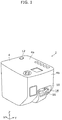
- FIG. 1 is a perspective view illustrating the appearance of printer 2 according to Embodiment 1.
- FIG. 2 is a perspective view illustrating printing unit 6 of printer 2 according to Embodiment 1. For convenience of the description, part of housing 4 is not illustrated in FIG. 2 .
- printer 2 includes housing 4, and printing unit 6 disposed inside housing 4.
- printer 2 is a so-called nail printer for printing a manicure color or motif on nail 10 of finger 8 of a hand of a user (one example of an object).
- Printer 2 can wirelessly communicate with an external terminal (not illustrated) such as a smartphone or a tablet terminal.
- the user can operate printer 2 using application software installed in the external terminal as an interface.
- housing 4 is made of a resin, and has a boxed shape.
- Top surface 4a of housing 4 includes power supply switch 12 for turning on/off the power supply of printer 2.
- front surface 4b of housing 4 includes opening 14 into which finger 8 of the user is inserted.
- finger holder 16 for placing finger 8 of the user is disposed in a lower portion of opening 14 (on the minus side of the Z-axis).
- press cover 18 for pressing finger 8 of the user from above is disposed above opening 14 (on the plus side of the Z-axis).
- Finger holder 16 can move vertically to press cover 18 (in the Z-axis direction), and is urged with a spring (not illustrated) in a direction approaching to press cover 18.
- mirror 17 is disposed on a lateral side of finger holder 16.
- Mirror 17 is a side view mirror having mirror surface 17a for reflecting a side of the surface of nail 10 of finger 8 placed on finger holder 16.
- Mirror 17 is disposed inclined to the vertical direction (Z-axis direction) such that mirror surface 17a faces obliquely upward.
- the user inserts finger 8 into opening 14 of housing 4 such that finger 8 extends straight and nail 10 of finger 8 faces upward (see FIG. 1 ), and places the palm side of finger 8 on finger holder 16.
- a portion of finger 8 including nail 10 (for example, a portion from the tip of finger 8 to near the first joint thereof) is disposed inside housing 4.
- finger holder 16 is urged in a direction approaching to press cover 18.
- a portion of finger 8 near the first joint is held from above and below the portion by finger holder 16 and press cover 18.
- Nail 10 of finger 8 disposed inside housing 4 is captured by camera unit 19 disposed above finger holder 16 to face finger holder 16.
- Camera unit 19 includes wiring substrate 19a disposed above finger holder 16 to face finger holder 16, and image capturer 19b mounted on a bottom surface of wiring substrate 19a.
- Wiring substrate 19a is held by an inner cover (not illustrated) disposed inside housing 4, for example.
- Image capturer 19b directly captures an image of the top of the surface of nail 10 of finger 8 placed on finger holder 16, and captures an image of the side of the surface of nail 10 of finger 8 reflected on mirror surface 17a of mirror 17.
- the image data of nail 10 captured by image capturer 19b is wirelessly transmitted from printer 2 to the external terminal, and is displayed on a display screen of the external terminal. The user views the image data of nail 10 presented on the display screen of the external terminal to check the position of nail 10 on finger holder 16.
- Printing unit 6 is a unit for performing manicure printing on nail 10 of finger 8 disposed inside housing 4.
- the printing method for printing unit 6 is an ink jet method of printing by spraying a mist of ink onto nail 10 of finger 8.
- printing unit 6 includes head 20, driving mechanism 22, head maintaining mechanism 24, interlocking mechanism 26 (see FIG. 4 described later), and lock mechanism 28 (see FIGs. 3 and 4 described later).
- Head 20 includes head holder 30 and ink head 31 mounted on head holder 30.
- Ink head 31 contains several color inks inside thereof.
- the bottom surface of head 20 includes nozzle face 32 (see FIGs. 4 and 6 described later) which ejects the ink downwardly toward nail 10 of finger 8.
- Driving mechanism 22 is a mechanism for two-dimensionally moving head 20 in a first direction (X-axis direction) and a second direction (Y-axis direction) approximately orthogonal to the first direction. A specific configuration of driving mechanism 22 will be described later.
- Head maintaining mechanism 24 is a mechanism for maintaining nozzle face 32 of head 20. Head maintaining mechanism 24 is disposed on one side (on the plus side of the Y-axis) with respect to the central portion of the moving region of head 20 in the second direction, and is disposed below nozzle face 32 of head 20. Head maintaining mechanism 24 includes cap holder 34, nozzle cap 36, and wiper 38.
- Cap holder 34 can move in a direction approaching to nozzle face 32 of head 20 and in a direction away from nozzle face 32.
- Nozzle cap 36 is a cap for capping (sealing) nozzle face 32 of head 20 in a standby position (described later), and is held by cap holder 34.
- Wiper 38 is a wiper blade for wiping (cleaning) nozzle face 32 of head 20, and is held by cap holder 34.
- Wiper 38 is made of a rubber or elastomer resin having flexibility, for example.
- Interlocking mechanism 26 is a mechanism for moving nozzle cap 36 held by cap holder 34 in the direction approaching to nozzle face 32 of head 20 in conjunction with the movement of head 20 from one side to the other side of the first direction (from the minus side to the plus side of the X-axis). A specific configuration of interlocking mechanism 26 will be described later.
- Lock mechanism 28 is a mechanism for regulating the movement of head 20 in the first direction and the second direction in the state where nozzle face 32 of head 20 is capped with nozzle cap 36. A specific configuration of lock mechanism 28 will be described later.
- FIG. 3 is a perspective view illustrating printing unit 6 of printer 2 according to Embodiment 1 where head 20 and Y-axis driving mechanism 22b are omitted.
- Driving mechanism 22 includes X-axis driving mechanism 22a for moving head 20 in the first direction, and Y-axis driving mechanism 22b for moving head 20 in the second direction.
- Y-axis driving mechanism 22b includes movable table 40, Y-axis guide shaft 42, Y-axis motor 44, and timing belt 46.
- Y-axis guide shaft 42 is held by movable table 40 disposed inside housing 4, and extends in the second direction in an elongated form. Head 20 is movably held by Y-axis guide shaft 42.
- Y-axis motor 44 is configured with a servomotor, for example, and is held by the bottom surface of movable table 40.
- the driving force of Y-axis motor 44 is transmitted through timing belt 46 to head 20.
- head 20 reciprocally moves on movable table 40 along Y-axis guide shaft 42 in the second direction.
- X-axis driving mechanism 22a includes movable table 40 (see FIG. 2 ), bearing member 48, X-axis guide shaft 50, X-axis motor 52 (one example of a driving source), worm gear 54, worm wheel 56, and drive conversion mechanism 58.
- X-axis guide shaft 50 is held by support plate 59 disposed inside housing 4, and extends in the first direction in an elongated form.
- Bearing member 48 fixed to the bottom surface of movable table 40 is movably held by X-axis guide shaft 50.
- movable table 40 is movably held by X-axis guide shaft 50 through bearing member 48.
- X-axis motor 52 is configured with a servomotor, for example, and is held by support plate 59.
- Worm gear 54 is rotatably held by the driving shaft of X-axis motor 52.
- Worm wheel 56 is rotatably held by support plate 59, and is engaged with worm gear 54.
- Drive conversion mechanism 58 is a mechanism for converting the rotation of worm wheel 56 to linear movement of head 20 in the first direction.
- Drive conversion mechanism 58 includes pinion gear 60 disposed in worm wheel 56, and rack gear 62 disposed in bearing member 48. Pinion gear 60 and rack gear 62 are engaged with each other.
- X-axis motor 52 The driving force of X-axis motor 52 is transmitted through worm gear 54, worm wheel 56, pinion gear 60, and rack gear 62 to movable table 40.
- head 20 reciprocally moves together with movable table 40 along X-axis guide shaft 50 in the first direction.
- Nail 10 of finger 8 is printed by ejecting the ink from nozzle face 32 of head 20 toward nail 10 of finger 8 in the state where head 20 is moving from the other side to one side of the first direction (from the plus side to the minus side of the X-axis) while reciprocally moving in the second direction.
- head 20 moves from the current location to the other side to one side of the first direction (from the plus side to the minus side of the X-axis), moves from the other side to one side of the second direction (from the minus side to the plus side of Y-axis), and once stops at the position (hereinafter, referred to as "relay position") illustrated in FIG. 2 and FIG. 4 (described later). Subsequently, head 20 further moves from one side to the other side of the first direction (from the minus side to the plus side of the X-axis), and stops at the position (hereinafter, referred to as "standby position") illustrated in FIG. 7 (described later).
- FIG. 4 is a side view illustrating printing unit 6 of printer 2 according to Embodiment 1 where nozzle cap 36 is in the second position.
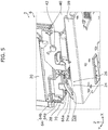
- FIG. 5 is a perspective view illustrating printing unit 6 of printer 2 according to Embodiment 1 where nozzle cap 36 is in the second position.
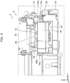
- FIG. 6 is a partially enlarged diagram illustrating printing unit 6 of printer 2 according to Embodiment 1 where nozzle cap 36 is in the second position.
- FIG. 7 is a side view illustrating printing unit 6 of printer 2 according to Embodiment 1 where nozzle cap 36 is in the first position.
- FIG. 8 is a perspective view illustrating printing unit 6 of printer 2 according to Embodiment 1 where nozzle cap 36 is in the first position.
- FIG. 9 is a partially enlarged diagram illustrating printing unit 6 of printer 2 according to Embodiment 1 where nozzle cap 36 is in the first position.
- housing 4 and the like are not illustrated in FIGs. 4 to 9 .
- interlocking mechanism 26 includes first engaging part 64, a pair of guide plates 66a and 66b, cap holder 34, urging member 68 (see FIG. 7 ), and second engaging part 70.
- first engaging part 64 is disposed at a lower end of the lateral surface of head 20.
- the shape thereof in an X-Y cross-section of first engaging part 64 is approximately L-shaped.
- first engaging part 64 includes first wall 64a extending approximately vertical from the lateral surface of head 20, and second wall 64b further extending approximately vertical from an end of first wall 64a.
- second wall 64b is disposed facing the lateral surface of head 20.
- a pair of guide plates 66a and 66b are held by support plate 59, and are disposed at an interval in the second direction.
- the pair of guide plates 66a and 66b include guide holes 72a and 72b, respectively.
- Guide holes 72a and 72b extend obliquely upward from one side to the other side of the first direction (from the minus side to the plus side of the X-axis).
- a pair of lateral surfaces of cap holder 34 facing each other in the second direction include protrusions 74a and 74b, respectively.
- Protrusions 74a and 74b are movably inserted into guide holes 72a and 72b, respectively.
- Protrusions 74a and 74b move along guide holes 72a and 72b, respectively, and as a result, nozzle cap 36 moves between the first position where nozzle face 32 of head 20 is capped (the position illustrated in FIGs. 7 to 9 ) and the second position away from nozzle face 32 where nozzle face 32 is uncapped (the position illustrated in FIGs. 4 to 6 ).
- urging member 68 is configured with a coil spring, for example, and urges nozzle cap 36 from the first position toward the second position.
- One end of urging member 68 is held by one of the lateral surfaces of cap holder 34, and the other end of urging member 68 is held by support plate 59.
- second engaging part 70 is formed into a plate shape, and extends from the upper end of one of the lateral surfaces of cap holder 34 toward head 20. When head 20 moves from the relay position to the standby position, second engaging part 70 engages with first engaging part 64.
- interlocking mechanism 26 As illustrated in FIGs. 4 to 6 , in the state where head 20 is in the relay position, nozzle cap 36 is held in the second position by the urging force from urging member 68, and first engaging part 64 is disengaged from second engaging part 70.
- Head 20 moves from the relay position toward the standby position (from one side to the other side of the first direction), and reaches a position between the relay position and the standby position (hereinafter, referred to as "intermediate position").
- intermediate position a position between the relay position and the standby position.
- second engaging part 70 is engaged with first wall 64a of first engaging part 64.
- head 20 further moves from the intermediate position toward the standby position in the state where first wall 64a of first engaging part 64 is engaged with second engaging part 70.
- nozzle cap 36 moves from the second position to the first position in conjunction with the movement of head 20 while nozzle cap 36 is resisting against the urging force from urging member 68.
- nozzle cap 36 reaches the first position to cap nozzle face 32 of head 20.
- first wall 64a of first engaging part 64 disengages from second engaging part 70.
- nozzle cap 36 moves from the first position to the second position by the urging force from urging member 68.
- lock mechanism 28 to regulate the movement of head 20 in the first direction will be described with reference to FIG. 3 , where nozzle cap 36 is in the first position.
- lock mechanism 28 is implemented with worm gear 54 and worm wheel 56.
- the lead helix angle of worm gear 54 is set to be less than or equal to the angle of friction. For this reason, in the state where the rotations of worm gear 54 and worm wheel 56 are stopped, the frictional resistance generated on the surfaces of the engaging teeth of worm gear 54 prevents worm gear 54 from being rotated from worm wheel 56 side, that is, a so-called self-locking acts. In other words, in the state where the driving of X-axis motor 52 is stopped, the rotation of worm gear 54 is self-locked even if an external force in the first direction is applied to head 20. Thus, head 20 is held in the standby position.
- lock mechanism 28 regulates the movement of head 20 in the first direction in the state where nozzle cap 36 is in the first position.
- lock mechanism 28 to regulate the movement of head 20 in the second direction will be described with reference to FIG. 8 , where nozzle cap 36 is in the first position.
- lock mechanism 28 is implemented with first engaging part 64 and second engaging part 70.
- second wall 64b of first engaging part 64 is engaged with second engaging part 70 in the state where head 20 is in the standby position. For this reason, head 20 is held in the standby position even if an external force from one side to the other side of the second direction (from the minus side to the plus side of the Y-axis) is applied to head 20.
- lock mechanism 28 regulates the movement of head 20 in the second direction in the state where nozzle cap 36 is in the first position.
- lock mechanism 28 regulates the movement of head 20 in the first direction and the second direction in the state where nozzle cap 36 is in the first position.
- head 20 can be prevented from unexpected movement in the first direction and the second direction with respect to nozzle cap 36.
- removal of nozzle cap 36 from nozzle face 32 of head 20 can be prevented, further ensuring capping of nozzle face 32 of head 20 with nozzle cap 36.
- FIG. 10 is a perspective view illustrating printing unit 6A of printer 2A according to Embodiment 2 in the state where nozzle cap 36 is in a first position.
- FIG. 11 is a perspective view illustrating printing unit 6A of printer 2A according to Embodiment 2 in the state where nozzle cap 36 is in a third position.
- FIG. 12 is a perspective view illustrating printing unit 6A of printer 2A according to Embodiment 2 in the state where nozzle cap 36 is in a second position.
- the same referential numerals will be given to the same components as those in Embodiment 1, and the descriptions thereof will be omitted.
- printer 2A includes printing unit 6A including holding mechanism 76.
- Holding mechanism 76 is a mechanism for holding nozzle cap 36 at a third position (the position illustrated in FIGs. 11 , 13 , and 14 (described later)) between a first position (the position illustrated in FIG. 10 ) and a second position (the position illustrated in FIG. 12 ).
- Holding mechanism 76 includes lever member 78, urging member 68A, and nail member 80. Nozzle face 32 of head 20 is wiped by wiper 38 in the state where holding mechanism 76 holds nozzle cap 36 in the third position.
- Lever member 78 is formed into a shape of an elongated plate. One end of lever member 78 in the longitudinal direction is rotatably held by rotary shaft 82 disposed on one of the lateral surfaces of cap holder 34. Lever member 78 extends from rotary shaft 82 to the other side of the first direction (the plus side of the X-axis). In other words, lever member 78 can swing around rotary shaft 82 vertically (within an X-Z plane).
- One lateral surface of lever member 78 in the lateral direction (the lateral surface facing head 20) includes cut-off portion 84 extending in the longitudinal direction of lever member 78.
- urging member 68A is held by one end of lever member 78, and the other end of urging member 68A is held by support plate 59.
- Nail member 80 is disposed at the upper end of support wall 86 erected from the top surface of support plate 59. Nail member 80 is engageable with one end 84a (the end close to rotary shaft 82) of cut-off portion 84 of lever member 78 and the other end 84b (the end remote from rotary shaft 82) thereof.
- FIG. 13 is a side view illustrating printing unit 6A of printer 2A according to Embodiment 2 in the state where nozzle cap 36 is in the third position.
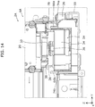
- FIG. 14 is a partially enlarged diagram illustrating printing unit 6A of printer 2A according to Embodiment 2 in the state where nozzle cap 36 is in the third position.
- nozzle face 32 of head 20 is capped with nozzle cap 36 (see FIG. 9 described above) in the first position in the state where head 20 is in the standby position.
- nail member 80 is engaged with one end 84a of cut-off portion 84 of lever member 78.
- nozzle cap 36 moves from the first position toward the third position by the urging force from urging member 68A, as illustrated in FIGs. 11 , 13 , and 14 .
- lever member 78 swings, and nail member 80 engages with the other end 84b of cut-off portion 84 of lever member 78.
- nozzle cap 36 stops moving, and is held in the third position.
- first engaging part 64 is disengaged from second engaging part 70.
- head 20 reciprocally moves in the second direction with respect to nozzle cap 36 in the state where nozzle cap 36 is held in the third position.
- nozzle face 32 of head 20 is wiped by wiper 38.
- nozzle face 32 of head 20 is held in a position allowing wiping by wiper 38 in the state where nozzle cap 36 is held in the third position.
- the tip of wiper 38 comes into contact with nozzle face 32 of head 20, so that wiper 38 elastically deforms and curves in the second direction.
- head 20 moves in the second direction, and returns to the position illustrated in FIG. 14 .
- head 20 further moves from the other side to one side of the first direction (from the plus side to the minus side of the X-axis) in the first direction in the state where nozzle cap 36 is held in the third position
- movable table 40 comes into contact with the other end of lever member 78.
- lever member 78 swings to disengage from nail member 80.
- nozzle cap 36 moves from the third position to the second position by the urging force of urging member 68A.
- nozzle face 32 of head 20 is held in a position not allowing wiping by wiper 38. For this reason, the tip of wiper 38 is not in contact with nozzle face 32 of head 20 when head 20 reciprocally moves in the second direction with respect to nozzle cap 36 in the state where nozzle cap 36 is in the second position.
- holding mechanism 76 holds nozzle cap 36 in the third position, nozzle face 32 of head 20 can be held in a position allowing wiping by wiper 38.
- Embodiments 1 and 2 of the present disclosure have been described above, but these embodiments should not be construed as limitations to the present disclosure. For example, the embodiments above may be combined.
- the present disclosure can be used as a printer for performing manicure printing on fingernails of hands of a user.
Landscapes
- Ink Jet (AREA)
Abstract
Description
- The present disclosure relates to a printer for printing on objects.
- Printers for printing manicure colors or motifs on fingernails of hands of users using an ink jet method are known (see
PTL 1, for example). The printer of this type includes a head having a nozzle face which ejects ink to a fingernail, and a driving mechanism which moves the head in a first direction and a second direction approximately orthogonal to the first direction. - Such a printer is configured to cap the nozzle face with a nozzle cap to prevent clogging caused by drying of the nozzle face when the head is in a standby position.
- [PTL 1]
Japanese Unexamined Patent Application Publication No. 2013-59579 - The printer described above is carried to a variety of places in a house for use, for example. However, vibration when the printer is being carried may unexpectedly move the head in the first direction and the second direction with respect to the nozzle cap, so that the nozzle cap may be removed from the nozzle face.
- The present disclosure has been made to solve such a problem above, and an object of the present disclosure is to provide a printer which ensures capping of a nozzle face of a head with a nozzle cap.
- To solve the above object, the printer according to one aspect of the present disclosure is a printer for printing on an object, the printer including: a head including a nozzle face which ejects ink toward the object; a driving mechanism which moves the head in a first direction and a second direction approximately orthogonal to the first direction; a nozzle cap movable between a first position where the nozzle face is capped and a second position where the nozzle face is uncapped; and a lock mechanism which regulates movement of the head in the first direction and the second direction in a state where the nozzle cap is in the first position.
- According to this aspect, the lock mechanism regulates the movement of the head in the first direction and the second direction in the state where the nozzle cap is in the first position. Thus, for example, even if any vibration is applied to the printer when the printer is being carried, the head can be prevented from unexpected movement in the first direction and the second direction with respect to the nozzle cap. As a result, removal of the nozzle cap from the nozzle face of the head can be prevented, ensuring capping of the nozzle face of the head with the nozzle cap.
- For example, in the printer according to one aspect of the present disclosure, the driving mechanism may be configured to include a driving source; a worm gear rotatable by the driving source; a worm wheel engaged with the worm gear; and a drive conversion mechanism which converts rotation of the worm wheel to movement of the head in the first direction. The lock mechanism may regulate the movement of the head in the first direction by utilizing a self-locking characteristic of the worm gear in the state where the nozzle cap is in the first position.
- According to this aspect, because the lock mechanism regulates the movement of the head in the first direction by utilizing a self-locking characteristic of the worm gear in the state where the nozzle cap is in the first position, the driving mechanism can also serve as the lock mechanism. As a result, the number of parts of the printer can be reduced, resulting in a smaller printer.
- For example, in the printer according to one aspect of the present disclosure, the printer may be configured to further include an interlocking mechanism which moves the nozzle cap from the second position to the first position in conjunction with movement of the head from one side to an other side in the first direction.
- According to this aspect, the nozzle cap can be moved from the second position to the first position by the interlocking mechanism in conjunction with the movement of the head.
- For example, in the printer according to one aspect of the present disclosure, the interlocking mechanism may be configured to include a first engaging part disposed in the head; a cap holder which holds the nozzle cap; and a second engaging part which is disposed in the cap holder and is engageable with the first engaging part. The first engaging part may be configured to engage with the second engaging part when the head moves from the one side to the other side in the first direction, causing the nozzle cap to move from the second position to the first position in conjunction with the movement of the head, and the lock mechanism may configured to regulate movement of the head in the second direction by utilizing engagement between the first engaging part and the second engaging part in the state where the nozzle cap is in the first position.
- According to this aspect, because the lock mechanism regulates the movement of the head in the second direction by utilizing the engagement between the first engaging part and the second engaging part in the state where the nozzle cap is in the first position, the interlocking mechanism can also serve as the lock mechanism. As a result, the number of parts of the printer can be reduced, resulting in a smaller printer.
- For example, in the printer according to one aspect of the present disclosure, the printer may be configured to further include a holding mechanism which holds the nozzle cap in a third position between the first position and the second position; and a wiper held by the cap holder. The head may move in the second direction with respect to the nozzle cap in the state where the nozzle cap is held in the third position, causing the wiper to wipe the nozzle face.
- According to this aspect, because the holding mechanism holds the nozzle cap in the third position, the nozzle face of the head can be held in a position allowing wiping by the wiper.
- For example, in the printer according to one aspect of the present disclosure, the holding mechanism may be configured to include an urging member which urges the nozzle cap from the first position toward the second position; a lever member rotatably held by the cap holder; and a nail member which is engageable with the lever member. When the head moves from the other side to the one side in the first direction in the state where the nozzle cap is in the first position, the nozzle cap may move from the first position toward the third position by an urging force from the urging member, the lever member swings to engage with the nail member, causing the nozzle cap to be held in the third position. When the head further moves from the other side to the one side in the first direction in the state where the nozzle cap is held in the third position, the lever member may swing to disengage from the nail member, allowing the urging force from the urging member to move the nozzle cap from the third position to the second position.
- According to this aspect, the holding mechanism can be implemented with a relatively simple configuration.
- The printer according to one aspect of the present disclosure can ensure capping of the nozzle face of the head with the nozzle cap.
-
- [
FIG. 1 ]
FIG. 1 is a perspective view illustrating the appearance of the printer according toEmbodiment 1. - [
FIG. 2 ]
FIG. 2 is a perspective view illustrating a printing unit of the printer according to Embodiment 1. - [
FIG. 3 ]
FIG. 3 is a perspective view illustrating the printing unit of the printer according toEmbodiment 1 where the head and the Y-axis driving mechanism are omitted. - [
FIG. 4 ]
FIG. 4 is a side view illustrating the printing unit of the printer according to Embodiment 1 where the nozzle cap is in a second position. - [
FIG. 5 ]
FIG. 5 is a perspective view illustrating the printing unit of the printer according to Embodiment 1 where the nozzle cap is in the second position. - [
FIG. 6 ]
FIG. 6 is a partially enlarged diagram illustrating the printing unit of the printer according toEmbodiment 1 where the nozzle cap is in the second position. - [
FIG. 7 ]
FIG. 7 is a side view illustrating the printing unit of the printer according to Embodiment 1 where the nozzle cap is in a first position. - [
FIG. 8 ]
FIG. 8 is a perspective view illustrating the printing unit of the printer according to Embodiment 1 where the nozzle cap is in the first position. - [
FIG. 9 ]
FIG. 9 is a partially enlarged diagram illustrating the printing unit of the printer according toEmbodiment 1 where the nozzle cap is in the first position. - [
FIG. 10 ]
FIG. 10 is a perspective view illustrating a printing unit of the printer according to Embodiment 2 where the nozzle cap is in the first position. - [
FIG. 11 ]
FIG. 11 is a perspective view illustrating the printing unit of the printer according to Embodiment 2 where the nozzle cap is in a third position. - [
FIG. 12 ]
FIG. 12 is a perspective view illustrating the printing unit of the printer according to Embodiment 2 where the nozzle cap is in the second position. - [
FIG. 13 ]
FIG. 13 is a side view illustrating the printing unit of the printer according to Embodiment 2 where the nozzle cap is in the third position. - [
FIG. 14 ]
FIG. 14 is a partially enlarged diagram illustrating the printing unit of the printer according toEmbodiment 2 where the nozzle cap is in the third position. - Embodiments according to the present disclosure will now be described in detail with reference to the drawings. The embodiments described below all illustrate comprehensive or specific examples. Numeric values, shapes, materials, components, arrangements and positions of the components, and connection forms thereof shown in the following embodiments are exemplary, and should not be construed as limitations to the present disclosure. Moreover, among the components of the embodiments below, the components not described in an independent claim will be described as arbitrary components.
- First, the configuration of
printer 2 according toEmbodiment 1 will be described with reference toFIGs. 1 and2 .FIG. 1 is a perspective view illustrating the appearance ofprinter 2 according toEmbodiment 1.FIG. 2 is a perspective view illustratingprinting unit 6 ofprinter 2 according toEmbodiment 1. For convenience of the description, part ofhousing 4 is not illustrated inFIG. 2 . - As illustrated in
FIGs. 1 and2 ,printer 2 includeshousing 4, andprinting unit 6 disposed insidehousing 4. In the present embodiment,printer 2 is a so-called nail printer for printing a manicure color or motif onnail 10 offinger 8 of a hand of a user (one example of an object). -
Printer 2 can wirelessly communicate with an external terminal (not illustrated) such as a smartphone or a tablet terminal. The user can operateprinter 2 using application software installed in the external terminal as an interface. - As illustrated in
FIG. 1 ,housing 4 is made of a resin, and has a boxed shape.Top surface 4a ofhousing 4 includespower supply switch 12 for turning on/off the power supply ofprinter 2. - As illustrated in
FIG. 1 ,front surface 4b ofhousing 4 includesopening 14 into whichfinger 8 of the user is inserted. As illustrated inFIGs. 1 and2 ,finger holder 16 for placingfinger 8 of the user is disposed in a lower portion of opening 14 (on the minus side of the Z-axis). As illustrated inFIG. 1 ,press cover 18 for pressingfinger 8 of the user from above is disposed above opening 14 (on the plus side of the Z-axis).Finger holder 16 can move vertically to press cover 18 (in the Z-axis direction), and is urged with a spring (not illustrated) in a direction approaching to presscover 18. - As illustrated in
FIGs. 2 and3 described later,mirror 17 is disposed on a lateral side offinger holder 16.Mirror 17 is a side view mirror havingmirror surface 17a for reflecting a side of the surface ofnail 10 offinger 8 placed onfinger holder 16.Mirror 17 is disposed inclined to the vertical direction (Z-axis direction) such thatmirror surface 17a faces obliquely upward. - As illustrated in
FIG. 2 , the user insertsfinger 8 into opening 14 ofhousing 4 such thatfinger 8 extends straight and nail 10 offinger 8 faces upward (seeFIG. 1 ), and places the palm side offinger 8 onfinger holder 16. Thereby, a portion offinger 8 including nail 10 (for example, a portion from the tip offinger 8 to near the first joint thereof) is disposed insidehousing 4. At this time,finger holder 16 is urged in a direction approaching to presscover 18. As a result, a portion offinger 8 near the first joint is held from above and below the portion byfinger holder 16 andpress cover 18. -
Nail 10 offinger 8 disposed insidehousing 4 is captured bycamera unit 19 disposed abovefinger holder 16 to facefinger holder 16.Camera unit 19 includeswiring substrate 19a disposed abovefinger holder 16 to facefinger holder 16, and image capturer 19b mounted on a bottom surface ofwiring substrate 19a.Wiring substrate 19a is held by an inner cover (not illustrated) disposed insidehousing 4, for example. Image capturer 19b directly captures an image of the top of the surface ofnail 10 offinger 8 placed onfinger holder 16, and captures an image of the side of the surface ofnail 10 offinger 8 reflected onmirror surface 17a ofmirror 17. The image data ofnail 10 captured by image capturer 19b is wirelessly transmitted fromprinter 2 to the external terminal, and is displayed on a display screen of the external terminal. The user views the image data ofnail 10 presented on the display screen of the external terminal to check the position ofnail 10 onfinger holder 16. -
Printing unit 6 is a unit for performing manicure printing onnail 10 offinger 8 disposed insidehousing 4. The printing method for printingunit 6 is an ink jet method of printing by spraying a mist of ink ontonail 10 offinger 8. - As illustrated in
FIG. 2 ,printing unit 6 includeshead 20, drivingmechanism 22,head maintaining mechanism 24, interlocking mechanism 26 (seeFIG. 4 described later), and lock mechanism 28 (seeFIGs. 3 and4 described later). -
Head 20 includeshead holder 30 andink head 31 mounted onhead holder 30.Ink head 31 contains several color inks inside thereof. The bottom surface ofhead 20 includes nozzle face 32 (seeFIGs. 4 and6 described later) which ejects the ink downwardly towardnail 10 offinger 8. - Driving
mechanism 22 is a mechanism for two-dimensionally movinghead 20 in a first direction (X-axis direction) and a second direction (Y-axis direction) approximately orthogonal to the first direction. A specific configuration of drivingmechanism 22 will be described later. -
Head maintaining mechanism 24 is a mechanism for maintainingnozzle face 32 ofhead 20.Head maintaining mechanism 24 is disposed on one side (on the plus side of the Y-axis) with respect to the central portion of the moving region ofhead 20 in the second direction, and is disposed belownozzle face 32 ofhead 20.Head maintaining mechanism 24 includescap holder 34,nozzle cap 36, andwiper 38. -
Cap holder 34 can move in a direction approaching tonozzle face 32 ofhead 20 and in a direction away fromnozzle face 32.Nozzle cap 36 is a cap for capping (sealing)nozzle face 32 ofhead 20 in a standby position (described later), and is held bycap holder 34.Wiper 38 is a wiper blade for wiping (cleaning)nozzle face 32 ofhead 20, and is held bycap holder 34.Wiper 38 is made of a rubber or elastomer resin having flexibility, for example. -
Interlocking mechanism 26 is a mechanism for movingnozzle cap 36 held bycap holder 34 in the direction approaching tonozzle face 32 ofhead 20 in conjunction with the movement ofhead 20 from one side to the other side of the first direction (from the minus side to the plus side of the X-axis). A specific configuration of interlockingmechanism 26 will be described later. -
Lock mechanism 28 is a mechanism for regulating the movement ofhead 20 in the first direction and the second direction in the state where nozzle face 32 ofhead 20 is capped withnozzle cap 36. A specific configuration oflock mechanism 28 will be described later. - Next, the configuration of driving
mechanism 22 will be described with reference toFIGs. 2 and3. FIG. 3 is a perspective view illustratingprinting unit 6 ofprinter 2 according toEmbodiment 1 wherehead 20 and Y-axis driving mechanism 22b are omitted. - Driving
mechanism 22 includesX-axis driving mechanism 22a for movinghead 20 in the first direction, and Y-axis driving mechanism 22b for movinghead 20 in the second direction. - As illustrated in
FIG. 2 , Y-axis driving mechanism 22b includes movable table 40, Y-axis guide shaft 42, Y-axis motor 44, andtiming belt 46. - Y-
axis guide shaft 42 is held by movable table 40 disposed insidehousing 4, and extends in the second direction in an elongated form.Head 20 is movably held by Y-axis guide shaft 42. Y-axis motor 44 is configured with a servomotor, for example, and is held by the bottom surface of movable table 40. - The driving force of Y-
axis motor 44 is transmitted throughtiming belt 46 to head 20. As a result,head 20 reciprocally moves on movable table 40 along Y-axis guide shaft 42 in the second direction. - As illustrated in
FIG. 3 ,X-axis driving mechanism 22a includes movable table 40 (seeFIG. 2 ), bearingmember 48,X-axis guide shaft 50, X-axis motor 52 (one example of a driving source),worm gear 54,worm wheel 56, and driveconversion mechanism 58. -
X-axis guide shaft 50 is held bysupport plate 59 disposed insidehousing 4, and extends in the first direction in an elongated form. Bearingmember 48 fixed to the bottom surface of movable table 40 is movably held byX-axis guide shaft 50. In other words, movable table 40 is movably held byX-axis guide shaft 50 through bearingmember 48.X-axis motor 52 is configured with a servomotor, for example, and is held bysupport plate 59.Worm gear 54 is rotatably held by the driving shaft ofX-axis motor 52.Worm wheel 56 is rotatably held bysupport plate 59, and is engaged withworm gear 54. -
Drive conversion mechanism 58 is a mechanism for converting the rotation ofworm wheel 56 to linear movement ofhead 20 in the first direction.Drive conversion mechanism 58 includespinion gear 60 disposed inworm wheel 56, andrack gear 62 disposed in bearingmember 48.Pinion gear 60 andrack gear 62 are engaged with each other. - The driving force of
X-axis motor 52 is transmitted throughworm gear 54,worm wheel 56,pinion gear 60, andrack gear 62 to movable table 40. As a result,head 20 reciprocally moves together with movable table 40 alongX-axis guide shaft 50 in the first direction. -
Nail 10 offinger 8 is printed by ejecting the ink fromnozzle face 32 ofhead 20 towardnail 10 offinger 8 in the state wherehead 20 is moving from the other side to one side of the first direction (from the plus side to the minus side of the X-axis) while reciprocally moving in the second direction. - After the printing is completed,
head 20 moves from the current location to the other side to one side of the first direction (from the plus side to the minus side of the X-axis), moves from the other side to one side of the second direction (from the minus side to the plus side of Y-axis), and once stops at the position (hereinafter, referred to as "relay position") illustrated inFIG. 2 andFIG. 4 (described later). Subsequently,head 20 further moves from one side to the other side of the first direction (from the minus side to the plus side of the X-axis), and stops at the position (hereinafter, referred to as "standby position") illustrated inFIG. 7 (described later). - Next, the configuration of interlocking
mechanism 26 will be described with reference toFIG. 2 andFIGs. 4 to 9 .FIG. 4 is a side view illustratingprinting unit 6 ofprinter 2 according toEmbodiment 1 wherenozzle cap 36 is in the second position.FIG. 5 is a perspective view illustratingprinting unit 6 ofprinter 2 according toEmbodiment 1 wherenozzle cap 36 is in the second position.FIG. 6 is a partially enlarged diagram illustratingprinting unit 6 ofprinter 2 according toEmbodiment 1 wherenozzle cap 36 is in the second position. -
FIG. 7 is a side view illustratingprinting unit 6 ofprinter 2 according toEmbodiment 1 wherenozzle cap 36 is in the first position.FIG. 8 is a perspective view illustratingprinting unit 6 ofprinter 2 according toEmbodiment 1 wherenozzle cap 36 is in the first position.FIG. 9 is a partially enlarged diagram illustratingprinting unit 6 ofprinter 2 according toEmbodiment 1 wherenozzle cap 36 is in the first position. For convenience of the description,housing 4 and the like are not illustrated inFIGs. 4 to 9 . - As illustrated in
FIGs. 4 to 6 ,interlocking mechanism 26 includes first engagingpart 64, a pair ofguide plates cap holder 34, urging member 68 (seeFIG. 7 ), and second engagingpart 70. - As illustrated in
FIG. 4 , first engagingpart 64 is disposed at a lower end of the lateral surface ofhead 20. As illustrated inFIG. 5 , the shape thereof in an X-Y cross-section of first engagingpart 64 is approximately L-shaped. In other words, first engagingpart 64 includesfirst wall 64a extending approximately vertical from the lateral surface ofhead 20, andsecond wall 64b further extending approximately vertical from an end offirst wall 64a. In other words,second wall 64b is disposed facing the lateral surface ofhead 20. - As illustrated in
FIG. 2 andFIGs. 4 to 6 , a pair ofguide plates support plate 59, and are disposed at an interval in the second direction. The pair ofguide plates guide holes Guide holes - As illustrated in
FIG. 2 andFIGs. 4 to 6 , a pair of lateral surfaces ofcap holder 34 facing each other in the second direction includeprotrusions Protrusions guide holes Protrusions guide holes nozzle cap 36 moves between the first position where nozzle face 32 ofhead 20 is capped (the position illustrated inFIGs. 7 to 9 ) and the second position away fromnozzle face 32 where nozzle face 32 is uncapped (the position illustrated inFIGs. 4 to 6 ). - As illustrated in
FIGs. 7 and8 , urgingmember 68 is configured with a coil spring, for example, and urgesnozzle cap 36 from the first position toward the second position. One end of urgingmember 68 is held by one of the lateral surfaces ofcap holder 34, and the other end of urgingmember 68 is held bysupport plate 59. - As illustrated in
FIGs. 4 and5 , second engagingpart 70 is formed into a plate shape, and extends from the upper end of one of the lateral surfaces ofcap holder 34 towardhead 20. Whenhead 20 moves from the relay position to the standby position, second engagingpart 70 engages with first engagingpart 64. - Next, the operation of interlocking
mechanism 26 will be described with reference toFIGs. 4 to 9 . As illustrated inFIGs. 4 to 6 , in the state wherehead 20 is in the relay position,nozzle cap 36 is held in the second position by the urging force from urgingmember 68, and first engagingpart 64 is disengaged from second engagingpart 70. -
Head 20 moves from the relay position toward the standby position (from one side to the other side of the first direction), and reaches a position between the relay position and the standby position (hereinafter, referred to as "intermediate position"). At this timing, second engagingpart 70 is engaged withfirst wall 64a of first engagingpart 64. - As illustrated in
FIGs. 7 to 9 ,head 20 further moves from the intermediate position toward the standby position in the state wherefirst wall 64a of first engagingpart 64 is engaged with second engagingpart 70. As a result,nozzle cap 36 moves from the second position to the first position in conjunction with the movement ofhead 20 whilenozzle cap 36 is resisting against the urging force from urgingmember 68. At the timing whenhead 20 reaches the standby position,nozzle cap 36 reaches the first position to capnozzle face 32 ofhead 20. - For example, when
head 20 moves from the standby position to the relay position at the start of printing,first wall 64a of first engagingpart 64 disengages from second engagingpart 70. Thereby,nozzle cap 36 moves from the first position to the second position by the urging force from urgingmember 68. - Next, the configuration of
lock mechanism 28 will be described. - First, the function of
lock mechanism 28 to regulate the movement ofhead 20 in the first direction will be described with reference toFIG. 3 , wherenozzle cap 36 is in the first position. In this case, as illustrated inFIG. 3 ,lock mechanism 28 is implemented withworm gear 54 andworm wheel 56. - Specifically, the lead helix angle of
worm gear 54 is set to be less than or equal to the angle of friction. For this reason, in the state where the rotations ofworm gear 54 andworm wheel 56 are stopped, the frictional resistance generated on the surfaces of the engaging teeth ofworm gear 54 preventsworm gear 54 from being rotated fromworm wheel 56 side, that is, a so-called self-locking acts. In other words, in the state where the driving ofX-axis motor 52 is stopped, the rotation ofworm gear 54 is self-locked even if an external force in the first direction is applied tohead 20. Thus,head 20 is held in the standby position. - As described above, by utilizing such a self-locking characteristic of
worm gear 54,lock mechanism 28 regulates the movement ofhead 20 in the first direction in the state wherenozzle cap 36 is in the first position. - Next, the function of
lock mechanism 28 to regulate the movement ofhead 20 in the second direction will be described with reference toFIG. 8 , wherenozzle cap 36 is in the first position. In this case, as illustrated inFIG. 8 ,lock mechanism 28 is implemented with first engagingpart 64 and second engagingpart 70. - Specifically,
second wall 64b of first engagingpart 64 is engaged with second engagingpart 70 in the state wherehead 20 is in the standby position. For this reason,head 20 is held in the standby position even if an external force from one side to the other side of the second direction (from the minus side to the plus side of the Y-axis) is applied tohead 20. - As described above, by utilizing the engagement between first engaging
part 64 and second engagingpart 70,lock mechanism 28 regulates the movement ofhead 20 in the second direction in the state wherenozzle cap 36 is in the first position. - As described above,
lock mechanism 28 regulates the movement ofhead 20 in the first direction and the second direction in the state wherenozzle cap 36 is in the first position. Thus, for example, even if any vibration is applied toprinter 2 whenprinter 2 is being carried,head 20 can be prevented from unexpected movement in the first direction and the second direction with respect tonozzle cap 36. As a result, removal ofnozzle cap 36 fromnozzle face 32 ofhead 20 can be prevented, further ensuring capping ofnozzle face 32 ofhead 20 withnozzle cap 36. - The configuration of
printer 2A according toEmbodiment 2 will be described with reference toFIGs. 10 to 12 .FIG. 10 is a perspective view illustratingprinting unit 6A ofprinter 2A according toEmbodiment 2 in the state wherenozzle cap 36 is in a first position.FIG. 11 is a perspective view illustratingprinting unit 6A ofprinter 2A according toEmbodiment 2 in the state wherenozzle cap 36 is in a third position.FIG. 12 is a perspective view illustratingprinting unit 6A ofprinter 2A according toEmbodiment 2 in the state wherenozzle cap 36 is in a second position. In the present embodiment, the same referential numerals will be given to the same components as those inEmbodiment 1, and the descriptions thereof will be omitted. - As illustrated in
FIGs. 10 to 12 , unlikeprinter 2 according toEmbodiment 1,printer 2A according to the present embodiment includesprinting unit 6A including holdingmechanism 76.Holding mechanism 76 is a mechanism for holdingnozzle cap 36 at a third position (the position illustrated inFIGs. 11 ,13 , and14 (described later)) between a first position (the position illustrated inFIG. 10 ) and a second position (the position illustrated inFIG. 12 ).Holding mechanism 76 includeslever member 78, urgingmember 68A, andnail member 80.Nozzle face 32 ofhead 20 is wiped bywiper 38 in the state where holdingmechanism 76 holdsnozzle cap 36 in the third position. -
Lever member 78 is formed into a shape of an elongated plate. One end oflever member 78 in the longitudinal direction is rotatably held byrotary shaft 82 disposed on one of the lateral surfaces ofcap holder 34.Lever member 78 extends fromrotary shaft 82 to the other side of the first direction (the plus side of the X-axis). In other words,lever member 78 can swing aroundrotary shaft 82 vertically (within an X-Z plane). One lateral surface oflever member 78 in the lateral direction (the lateral surface facing head 20) includes cut-offportion 84 extending in the longitudinal direction oflever member 78. - One end of urging
member 68A is held by one end oflever member 78, and the other end of urgingmember 68A is held bysupport plate 59. -
Nail member 80 is disposed at the upper end ofsupport wall 86 erected from the top surface ofsupport plate 59.Nail member 80 is engageable with oneend 84a (the end close to rotary shaft 82) of cut-offportion 84 oflever member 78 and theother end 84b (the end remote from rotary shaft 82) thereof. - Next, the operation of holding
mechanism 76 will be described with reference toFIGs. 10 to 14 .FIG. 13 is a side view illustratingprinting unit 6A ofprinter 2A according toEmbodiment 2 in the state wherenozzle cap 36 is in the third position.FIG. 14 is a partially enlarged diagram illustratingprinting unit 6A ofprinter 2A according toEmbodiment 2 in the state wherenozzle cap 36 is in the third position. - As illustrated in
FIG. 10 , nozzle face 32 of head 20 (seeFIG. 9 described above) is capped with nozzle cap 36 (seeFIG. 9 described above) in the first position in the state wherehead 20 is in the standby position. At this time,nail member 80 is engaged with oneend 84a of cut-offportion 84 oflever member 78. - For example, when
head 20 moves from the other side to one side in the first direction (from the plus side to the minus side of the X-axis) in the first direction at the start of printing in the state wherenozzle cap 36 is in the first position,nozzle cap 36 moves from the first position toward the third position by the urging force from urgingmember 68A, as illustrated inFIGs. 11 ,13 , and14 . At this time,lever member 78 swings, andnail member 80 engages with theother end 84b of cut-offportion 84 oflever member 78. As a result,nozzle cap 36 stops moving, and is held in the third position. At this time, first engagingpart 64 is disengaged from second engagingpart 70. - As illustrated in
FIG. 14 ,head 20 reciprocally moves in the second direction with respect tonozzle cap 36 in the state wherenozzle cap 36 is held in the third position. As a result, nozzle face 32 ofhead 20 is wiped bywiper 38. In other words, nozzle face 32 ofhead 20 is held in a position allowing wiping bywiper 38 in the state wherenozzle cap 36 is held in the third position. During wiping, the tip ofwiper 38 comes into contact withnozzle face 32 ofhead 20, so thatwiper 38 elastically deforms and curves in the second direction. - After the wiping is completed,
head 20 moves in the second direction, and returns to the position illustrated inFIG. 14 . Whenhead 20 further moves from the other side to one side of the first direction (from the plus side to the minus side of the X-axis) in the first direction in the state wherenozzle cap 36 is held in the third position, movable table 40 comes into contact with the other end oflever member 78. As a result,lever member 78 swings to disengage fromnail member 80. Thereby, as illustrated inFIG. 12 ,nozzle cap 36 moves from the third position to the second position by the urging force of urgingmember 68A. - In the state where
nozzle cap 36 is in the second position, nozzle face 32 ofhead 20 is held in a position not allowing wiping bywiper 38. For this reason, the tip ofwiper 38 is not in contact withnozzle face 32 ofhead 20 whenhead 20 reciprocally moves in the second direction with respect tonozzle cap 36 in the state wherenozzle cap 36 is in the second position. - As described above, because holding
mechanism 76 holdsnozzle cap 36 in the third position, nozzle face 32 ofhead 20 can be held in a position allowing wiping bywiper 38. - The printers according to
Embodiments - Although printing is performed on
nail 10 offinger 8 of the hand of the user by printer 2 (2A) in the embodiments above, printing may be performed on any other objects such as a golf ball. - The present disclosure can be used as a printer for performing manicure printing on fingernails of hands of a user.
-
- 2, 2A
- printer
- 4
- housing
- 4a
- top surface
- 4b
- front surface
- 6, 6A
- printing unit
- 8
- finger
- 10
- nail
- 12
- power supply switch
- 14
- opening
- 16
- finger holder
- 17
- mirror
- 17a
- mirror surface
- 18
- press cover
- 19
- camera unit
- 19a
- wiring substrate
- 19b
- image capturer
- 20
- head
- 22
- driving mechanism
- 22a
- X-axis driving mechanism
- 22b
- Y-axis driving mechanism
- 24
- head maintaining mechanism
- 26
- interlocking mechanism
- 28
- lock mechanism
- 30
- head holder
- 31
- ink head
- 32
- nozzle face
- 34
- cap holder
- 36
- nozzle cap
- 38
- wiper
- 40
- movable table
- 42
- Y-axis guide shaft
- 44
- Y-axis motor
- 46
- timing belt
- 48
- bearing member
- 50
- X-axis guide shaft
- 52
- X-axis motor
- 54
- worm gear
- 56
- worm wheel
- 58
- drive conversion mechanism
- 59
- support plate
- 60
- pinion gear
- 62
- rack gear
- 64
- first engaging part
- 64a
- first wall
- 64b
- second wall
- 66a, 66b
- guide plate
- 68, 68A
- urging member
- 70
- second engaging part
- 72a, 72b
- guide hole
- 74a, 74b
- protrusion
- 76
- holding mechanism
- 78
- lever member
- 80
- nail member
- 82
- rotary shaft
- 84
- cut-off portion
- 84a
- one end
- 84b
- other end
- 86
- support wall
Claims (6)
- A printer for printing on an object, the printer comprising:a head including a nozzle face which ejects ink toward the object;a driving mechanism which moves the head in a first direction and a second direction approximately orthogonal to the first direction;a nozzle cap movable between a first position where the nozzle face is capped and a second position where the nozzle face is uncapped; anda lock mechanism which regulates movement of the head in the first direction and the second direction in a state where the nozzle cap is in the first position.
- The printer according to claim 1,wherein the driving mechanism includes:a driving source;a worm gear rotatable by the driving source;a worm wheel engaged with the worm gear; anda drive conversion mechanism which converts rotation of the worm wheel to movement of the head in the first direction, andthe lock mechanism regulates the movement of the head in the first direction by utilizing a self-locking characteristic of the worm gear in the state where the nozzle cap is in the first position.
- The printer according to claim 1 or 2, further comprising:
an interlocking mechanism which moves the nozzle cap from the second position to the first position in conjunction with movement of the head from one side to another side in the first direction. - The printer according to claim 3,
wherein the interlocking mechanism includes:a first engaging part disposed in the head;a cap holder which holds the nozzle cap; anda second engaging part which is disposed in the cap holder and is engageable with the first engaging part,the first engaging part engages with the second engaging part when the head moves from the one side to the other side in the first direction, causing the nozzle cap to move from the second position to the first position in conjunction with the movement of the head, andthe lock mechanism regulates movement of the head in the second direction by utilizing engagement between the first engaging part and the second engaging part in the state where the nozzle cap is in the first position. - The printer according to claim 4, further comprising:a holding mechanism which holds the nozzle cap in a third position between the first position and the second position; anda wiper held by the cap holder,wherein the head moves in the second direction with respect to the nozzle cap in the state where the nozzle cap is held in the third position, causing the wiper to wipe the nozzle face.
- The printer according to claim 5, wherein the holding mechanism includes:an urging member which urges the nozzle cap from the first position toward the second position;a lever member rotatably held by the cap holder; anda nail member which is engageable with the lever member,when the head moves from the other side to the one side in the first direction in the state where the nozzle cap is in the first position, the nozzle cap moves from the first position toward the third position by an urging force from the urging member, the lever member swings to engage with the nail member, causing the nozzle cap to be held in the third position, andwhen the head further moves from the other side to the one side in the first direction in the state where the nozzle cap is held in the third position, the lever member swings to disengage from the nail member, allowing the urging force from the urging member to move the nozzle cap from the third position to the second position.
Applications Claiming Priority (2)
| Application Number | Priority Date | Filing Date | Title |
|---|---|---|---|
| US201862773520P | 2018-11-30 | 2018-11-30 | |
| PCT/JP2019/021249 WO2020110352A1 (en) | 2018-11-30 | 2019-05-29 | Printer |
Publications (3)
| Publication Number | Publication Date |
|---|---|
| EP3888488A1 true EP3888488A1 (en) | 2021-10-06 |
| EP3888488A4 EP3888488A4 (en) | 2022-08-17 |
| EP3888488B1 EP3888488B1 (en) | 2024-07-03 |
Family
ID=70852754
Family Applications (1)
| Application Number | Title | Priority Date | Filing Date |
|---|---|---|---|
| EP19888787.9A Active EP3888488B1 (en) | 2018-11-30 | 2019-05-29 | Printer |
Country Status (5)
| Country | Link |
|---|---|
| US (1) | US11260663B2 (en) |
| EP (1) | EP3888488B1 (en) |
| JP (1) | JP7415942B2 (en) |
| CN (1) | CN111989009B (en) |
| WO (1) | WO2020110352A1 (en) |
Families Citing this family (2)
| Publication number | Priority date | Publication date | Assignee | Title |
|---|---|---|---|---|
| JP7512771B2 (en) * | 2020-08-27 | 2024-07-09 | カシオ計算機株式会社 | Maintenance device and printing device |
| JP2023018278A (en) * | 2021-07-27 | 2023-02-08 | キヤノン株式会社 | Droplet ejection device and its control method |
Family Cites Families (25)
| Publication number | Priority date | Publication date | Assignee | Title |
|---|---|---|---|---|
| JP2002187287A (en) | 2000-12-21 | 2002-07-02 | Seiko Epson Corp | Ink jet recording device |
| JP2003197998A (en) * | 2001-12-27 | 2003-07-11 | Denso Corp | Manufacturing method of laminated piezoelectric element |
| US7824001B2 (en) * | 2004-09-21 | 2010-11-02 | Z Corporation | Apparatus and methods for servicing 3D printers |
| JP2006130666A (en) | 2004-11-02 | 2006-05-25 | Seiko Epson Corp | Liquid ejector |
| KR100667847B1 (en) * | 2005-12-23 | 2007-01-11 | 삼성전자주식회사 | Inkjet image forming apparatus |
| JP5262471B2 (en) * | 2008-09-05 | 2013-08-14 | セイコーエプソン株式会社 | Recording apparatus and tray control method in recording apparatus |
| JP2011214792A (en) | 2010-04-01 | 2011-10-27 | Matex Kk | Motor type damper device |
| JP2012250396A (en) | 2011-06-01 | 2012-12-20 | Ricoh Co Ltd | Inkjet recording apparatus |
| US9434179B2 (en) | 2011-07-19 | 2016-09-06 | Casio Computer Co., Ltd. | Nail print apparatus |
| JP5321650B2 (en) * | 2011-07-19 | 2013-10-23 | カシオ計算機株式会社 | Nail printing device |
| JP5348214B2 (en) | 2011-09-15 | 2013-11-20 | カシオ計算機株式会社 | Nail printer |
| JP2014040020A (en) | 2012-08-21 | 2014-03-06 | Canon Inc | Colorimetric device |
| JP2014158638A (en) * | 2013-02-21 | 2014-09-04 | Casio Comput Co Ltd | Nail printing device |
| JP6127793B2 (en) * | 2013-07-18 | 2017-05-17 | カシオ計算機株式会社 | Nail printing apparatus and printing method for nail printing apparatus |
| JP6167728B2 (en) * | 2013-07-26 | 2017-07-26 | カシオ計算機株式会社 | Nail printing apparatus and control method for nail printing apparatus |
| JP6303413B2 (en) * | 2013-11-11 | 2018-04-04 | カシオ計算機株式会社 | Nail printing apparatus and printing method for nail printing apparatus |
| JP2015116429A (en) * | 2013-12-20 | 2015-06-25 | カシオ計算機株式会社 | Nail printing apparatus and printing control method for nail printing apparatus |
| JP6331409B2 (en) * | 2014-01-20 | 2018-05-30 | カシオ計算機株式会社 | Drawing apparatus and drawing control method of drawing apparatus |
| JP2016059735A (en) * | 2014-09-22 | 2016-04-25 | カシオ計算機株式会社 | Drawing device |
| JP6557485B2 (en) | 2015-03-12 | 2019-08-07 | 株式会社トプコン | Surveyor drive mechanism |
| JP6582611B2 (en) * | 2015-06-25 | 2019-10-02 | カシオ計算機株式会社 | Drawing apparatus and drawing method of drawing apparatus |
| JP2017118896A (en) * | 2015-12-28 | 2017-07-06 | カシオ計算機株式会社 | Drawing device |
| JP2017012897A (en) * | 2016-10-26 | 2017-01-19 | カシオ計算機株式会社 | Nail printing device |
| JP2018153940A (en) | 2017-03-15 | 2018-10-04 | 船井電機株式会社 | Image drawing apparatus |
| JP6344497B2 (en) * | 2017-03-30 | 2018-06-20 | カシオ計算機株式会社 | Nail printing apparatus and printing method for nail printing apparatus |
-
2019
- 2019-05-29 US US17/049,769 patent/US11260663B2/en active Active
- 2019-05-29 JP JP2020557547A patent/JP7415942B2/en active Active
- 2019-05-29 EP EP19888787.9A patent/EP3888488B1/en active Active
- 2019-05-29 WO PCT/JP2019/021249 patent/WO2020110352A1/en not_active Ceased
- 2019-05-29 CN CN201980026726.3A patent/CN111989009B/en active Active
Also Published As
| Publication number | Publication date |
|---|---|
| JPWO2020110352A1 (en) | 2021-10-21 |
| CN111989009B (en) | 2023-04-28 |
| EP3888488B1 (en) | 2024-07-03 |
| US11260663B2 (en) | 2022-03-01 |
| EP3888488A4 (en) | 2022-08-17 |
| WO2020110352A1 (en) | 2020-06-04 |
| CN111989009A (en) | 2020-11-24 |
| US20210235841A1 (en) | 2021-08-05 |
| JP7415942B2 (en) | 2024-01-17 |
Similar Documents
| Publication | Publication Date | Title |
|---|---|---|
| EP3888488B1 (en) | Printer | |
| CA2458598A1 (en) | Printer including printhead capping mechanism | |
| JP6167728B2 (en) | Nail printing apparatus and control method for nail printing apparatus | |
| EP1314564B1 (en) | Head maintenance mechanism for ink jet printer and ink jet printer incorporating the same | |
| CN106539270A (en) | Lid mechanism, drawing apparatus and plotting method | |
| CN106333468B (en) | Injection device | |
| US11331934B2 (en) | Printer | |
| EP1826008A3 (en) | Head capping member, head maintenance or recovery device, device for ejecting a liquid drop, and image forming apparatus | |
| HK1052322A1 (en) | Positive stop capping system for inkjet printheads | |
| CN105702513A (en) | Knob convenient to operate | |
| CN209707915U (en) | Handle box | |
| CN106114021A (en) | A kind of movement of electric pencil sharpener | |
| WO2017031997A1 (en) | Fastenable ink cartridge and ink cartridge connecting to cartridge retainer | |
| JP2021529109A (en) | Docking station | |
| CN207630751U (en) | A kind of service station of ink-jet printer | |
| CN110661958B (en) | Electronic device | |
| JP2008018552A (en) | Screw concealing cap device, recording device, and liquid ejecting device | |
| JP5126494B2 (en) | Cover opening / closing device, recording device | |
| CN105286266B (en) | Drawing apparatus | |
| EP1717037A3 (en) | Wiper device and liquid ejection apparatus | |
| JP2008081123A (en) | Trigger spray and spray container equipped with the same | |
| CN216423474U (en) | Shower nozzle protection device and 3D printer | |
| CN206030905U (en) | Electric pencil sharpener's core | |
| JP5523857B2 (en) | Connected structure | |
| CN216268207U (en) | But dustproof shower nozzle protection architecture of self-sealing |
Legal Events
| Date | Code | Title | Description |
|---|---|---|---|
| STAA | Information on the status of an ep patent application or granted ep patent |
Free format text: STATUS: THE INTERNATIONAL PUBLICATION HAS BEEN MADE |
|
| PUAI | Public reference made under article 153(3) epc to a published international application that has entered the european phase |
Free format text: ORIGINAL CODE: 0009012 |
|
| STAA | Information on the status of an ep patent application or granted ep patent |
Free format text: STATUS: REQUEST FOR EXAMINATION WAS MADE |
|
| 17P | Request for examination filed |
Effective date: 20201022 |
|
| AK | Designated contracting states |
Kind code of ref document: A1 Designated state(s): AL AT BE BG CH CY CZ DE DK EE ES FI FR GB GR HR HU IE IS IT LI LT LU LV MC MK MT NL NO PL PT RO RS SE SI SK SM TR |
|
| DAV | Request for validation of the european patent (deleted) | ||
| DAX | Request for extension of the european patent (deleted) | ||
| A4 | Supplementary search report drawn up and despatched |
Effective date: 20220719 |
|
| RIC1 | Information provided on ipc code assigned before grant |
Ipc: B41J 25/00 20060101ALI20220713BHEP Ipc: A45D 29/00 20060101ALI20220713BHEP Ipc: B41J 3/407 20060101ALI20220713BHEP Ipc: B41J 2/165 20060101ALI20220713BHEP Ipc: B41J 2/01 20060101ALI20220713BHEP Ipc: A45D 29/18 20060101AFI20220713BHEP |
|
| GRAP | Despatch of communication of intention to grant a patent |
Free format text: ORIGINAL CODE: EPIDOSNIGR1 |
|
| STAA | Information on the status of an ep patent application or granted ep patent |
Free format text: STATUS: GRANT OF PATENT IS INTENDED |
|
| INTG | Intention to grant announced |
Effective date: 20240228 |
|
| GRAS | Grant fee paid |
Free format text: ORIGINAL CODE: EPIDOSNIGR3 |
|
| GRAA | (expected) grant |
Free format text: ORIGINAL CODE: 0009210 |
|
| STAA | Information on the status of an ep patent application or granted ep patent |
Free format text: STATUS: THE PATENT HAS BEEN GRANTED |
|
| AK | Designated contracting states |
Kind code of ref document: B1 Designated state(s): AL AT BE BG CH CY CZ DE DK EE ES FI FR GB GR HR HU IE IS IT LI LT LU LV MC MK MT NL NO PL PT RO RS SE SI SK SM TR |
|
| REG | Reference to a national code |
Ref country code: CH Ref legal event code: EP |
|
| REG | Reference to a national code |
Ref country code: DE Ref legal event code: R096 Ref document number: 602019054791 Country of ref document: DE |
|
| REG | Reference to a national code |
Ref country code: LT Ref legal event code: MG9D |
|
| REG | Reference to a national code |
Ref country code: NL Ref legal event code: MP Effective date: 20240703 |
|
| PG25 | Lapsed in a contracting state [announced via postgrant information from national office to epo] |
Ref country code: PT Free format text: LAPSE BECAUSE OF FAILURE TO SUBMIT A TRANSLATION OF THE DESCRIPTION OR TO PAY THE FEE WITHIN THE PRESCRIBED TIME-LIMIT Effective date: 20241104 |
|
| REG | Reference to a national code |
Ref country code: AT Ref legal event code: MK05 Ref document number: 1698873 Country of ref document: AT Kind code of ref document: T Effective date: 20240703 |
|
| PG25 | Lapsed in a contracting state [announced via postgrant information from national office to epo] |
Ref country code: NL Free format text: LAPSE BECAUSE OF FAILURE TO SUBMIT A TRANSLATION OF THE DESCRIPTION OR TO PAY THE FEE WITHIN THE PRESCRIBED TIME-LIMIT Effective date: 20240703 |
|
| PG25 | Lapsed in a contracting state [announced via postgrant information from national office to epo] |
Ref country code: PT Free format text: LAPSE BECAUSE OF FAILURE TO SUBMIT A TRANSLATION OF THE DESCRIPTION OR TO PAY THE FEE WITHIN THE PRESCRIBED TIME-LIMIT Effective date: 20241104 Ref country code: NL Free format text: LAPSE BECAUSE OF FAILURE TO SUBMIT A TRANSLATION OF THE DESCRIPTION OR TO PAY THE FEE WITHIN THE PRESCRIBED TIME-LIMIT Effective date: 20240703 |
|
| PG25 | Lapsed in a contracting state [announced via postgrant information from national office to epo] |
Ref country code: NO Free format text: LAPSE BECAUSE OF FAILURE TO SUBMIT A TRANSLATION OF THE DESCRIPTION OR TO PAY THE FEE WITHIN THE PRESCRIBED TIME-LIMIT Effective date: 20241003 |
|
| PG25 | Lapsed in a contracting state [announced via postgrant information from national office to epo] |
Ref country code: FI Free format text: LAPSE BECAUSE OF FAILURE TO SUBMIT A TRANSLATION OF THE DESCRIPTION OR TO PAY THE FEE WITHIN THE PRESCRIBED TIME-LIMIT Effective date: 20240703 Ref country code: GR Free format text: LAPSE BECAUSE OF FAILURE TO SUBMIT A TRANSLATION OF THE DESCRIPTION OR TO PAY THE FEE WITHIN THE PRESCRIBED TIME-LIMIT Effective date: 20241004 Ref country code: PL Free format text: LAPSE BECAUSE OF FAILURE TO SUBMIT A TRANSLATION OF THE DESCRIPTION OR TO PAY THE FEE WITHIN THE PRESCRIBED TIME-LIMIT Effective date: 20240703 |
|
| PG25 | Lapsed in a contracting state [announced via postgrant information from national office to epo] |
Ref country code: BG Free format text: LAPSE BECAUSE OF FAILURE TO SUBMIT A TRANSLATION OF THE DESCRIPTION OR TO PAY THE FEE WITHIN THE PRESCRIBED TIME-LIMIT Effective date: 20240703 |
|
| PG25 | Lapsed in a contracting state [announced via postgrant information from national office to epo] |
Ref country code: LV Free format text: LAPSE BECAUSE OF FAILURE TO SUBMIT A TRANSLATION OF THE DESCRIPTION OR TO PAY THE FEE WITHIN THE PRESCRIBED TIME-LIMIT Effective date: 20240703 |
|
| PG25 | Lapsed in a contracting state [announced via postgrant information from national office to epo] |
Ref country code: AT Free format text: LAPSE BECAUSE OF FAILURE TO SUBMIT A TRANSLATION OF THE DESCRIPTION OR TO PAY THE FEE WITHIN THE PRESCRIBED TIME-LIMIT Effective date: 20240703 Ref country code: IS Free format text: LAPSE BECAUSE OF FAILURE TO SUBMIT A TRANSLATION OF THE DESCRIPTION OR TO PAY THE FEE WITHIN THE PRESCRIBED TIME-LIMIT Effective date: 20241103 |
|
| PG25 | Lapsed in a contracting state [announced via postgrant information from national office to epo] |
Ref country code: CZ Free format text: LAPSE BECAUSE OF FAILURE TO SUBMIT A TRANSLATION OF THE DESCRIPTION OR TO PAY THE FEE WITHIN THE PRESCRIBED TIME-LIMIT Effective date: 20240703 Ref country code: HR Free format text: LAPSE BECAUSE OF FAILURE TO SUBMIT A TRANSLATION OF THE DESCRIPTION OR TO PAY THE FEE WITHIN THE PRESCRIBED TIME-LIMIT Effective date: 20240703 |
|
| PG25 | Lapsed in a contracting state [announced via postgrant information from national office to epo] |
Ref country code: RS Free format text: LAPSE BECAUSE OF FAILURE TO SUBMIT A TRANSLATION OF THE DESCRIPTION OR TO PAY THE FEE WITHIN THE PRESCRIBED TIME-LIMIT Effective date: 20241003 Ref country code: ES Free format text: LAPSE BECAUSE OF FAILURE TO SUBMIT A TRANSLATION OF THE DESCRIPTION OR TO PAY THE FEE WITHIN THE PRESCRIBED TIME-LIMIT Effective date: 20240703 |
|
| PG25 | Lapsed in a contracting state [announced via postgrant information from national office to epo] |
Ref country code: RS Free format text: LAPSE BECAUSE OF FAILURE TO SUBMIT A TRANSLATION OF THE DESCRIPTION OR TO PAY THE FEE WITHIN THE PRESCRIBED TIME-LIMIT Effective date: 20241003 Ref country code: PL Free format text: LAPSE BECAUSE OF FAILURE TO SUBMIT A TRANSLATION OF THE DESCRIPTION OR TO PAY THE FEE WITHIN THE PRESCRIBED TIME-LIMIT Effective date: 20240703 Ref country code: NO Free format text: LAPSE BECAUSE OF FAILURE TO SUBMIT A TRANSLATION OF THE DESCRIPTION OR TO PAY THE FEE WITHIN THE PRESCRIBED TIME-LIMIT Effective date: 20241003 Ref country code: LV Free format text: LAPSE BECAUSE OF FAILURE TO SUBMIT A TRANSLATION OF THE DESCRIPTION OR TO PAY THE FEE WITHIN THE PRESCRIBED TIME-LIMIT Effective date: 20240703 Ref country code: IS Free format text: LAPSE BECAUSE OF FAILURE TO SUBMIT A TRANSLATION OF THE DESCRIPTION OR TO PAY THE FEE WITHIN THE PRESCRIBED TIME-LIMIT Effective date: 20241103 Ref country code: HR Free format text: LAPSE BECAUSE OF FAILURE TO SUBMIT A TRANSLATION OF THE DESCRIPTION OR TO PAY THE FEE WITHIN THE PRESCRIBED TIME-LIMIT Effective date: 20240703 Ref country code: GR Free format text: LAPSE BECAUSE OF FAILURE TO SUBMIT A TRANSLATION OF THE DESCRIPTION OR TO PAY THE FEE WITHIN THE PRESCRIBED TIME-LIMIT Effective date: 20241004 Ref country code: FI Free format text: LAPSE BECAUSE OF FAILURE TO SUBMIT A TRANSLATION OF THE DESCRIPTION OR TO PAY THE FEE WITHIN THE PRESCRIBED TIME-LIMIT Effective date: 20240703 Ref country code: ES Free format text: LAPSE BECAUSE OF FAILURE TO SUBMIT A TRANSLATION OF THE DESCRIPTION OR TO PAY THE FEE WITHIN THE PRESCRIBED TIME-LIMIT Effective date: 20240703 Ref country code: CZ Free format text: LAPSE BECAUSE OF FAILURE TO SUBMIT A TRANSLATION OF THE DESCRIPTION OR TO PAY THE FEE WITHIN THE PRESCRIBED TIME-LIMIT Effective date: 20240703 Ref country code: BG Free format text: LAPSE BECAUSE OF FAILURE TO SUBMIT A TRANSLATION OF THE DESCRIPTION OR TO PAY THE FEE WITHIN THE PRESCRIBED TIME-LIMIT Effective date: 20240703 Ref country code: AT Free format text: LAPSE BECAUSE OF FAILURE TO SUBMIT A TRANSLATION OF THE DESCRIPTION OR TO PAY THE FEE WITHIN THE PRESCRIBED TIME-LIMIT Effective date: 20240703 |
|
| REG | Reference to a national code |
Ref country code: DE Ref legal event code: R097 Ref document number: 602019054791 Country of ref document: DE |
|
| PG25 | Lapsed in a contracting state [announced via postgrant information from national office to epo] |
Ref country code: SM Free format text: LAPSE BECAUSE OF FAILURE TO SUBMIT A TRANSLATION OF THE DESCRIPTION OR TO PAY THE FEE WITHIN THE PRESCRIBED TIME-LIMIT Effective date: 20240703 Ref country code: DK Free format text: LAPSE BECAUSE OF FAILURE TO SUBMIT A TRANSLATION OF THE DESCRIPTION OR TO PAY THE FEE WITHIN THE PRESCRIBED TIME-LIMIT Effective date: 20240703 Ref country code: RO Free format text: LAPSE BECAUSE OF FAILURE TO SUBMIT A TRANSLATION OF THE DESCRIPTION OR TO PAY THE FEE WITHIN THE PRESCRIBED TIME-LIMIT Effective date: 20240703 |
|
| PG25 | Lapsed in a contracting state [announced via postgrant information from national office to epo] |
Ref country code: EE Free format text: LAPSE BECAUSE OF FAILURE TO SUBMIT A TRANSLATION OF THE DESCRIPTION OR TO PAY THE FEE WITHIN THE PRESCRIBED TIME-LIMIT Effective date: 20240703 |
|
| PG25 | Lapsed in a contracting state [announced via postgrant information from national office to epo] |
Ref country code: IT Free format text: LAPSE BECAUSE OF FAILURE TO SUBMIT A TRANSLATION OF THE DESCRIPTION OR TO PAY THE FEE WITHIN THE PRESCRIBED TIME-LIMIT Effective date: 20240703 Ref country code: SK Free format text: LAPSE BECAUSE OF FAILURE TO SUBMIT A TRANSLATION OF THE DESCRIPTION OR TO PAY THE FEE WITHIN THE PRESCRIBED TIME-LIMIT Effective date: 20240703 |
|
| PLBE | No opposition filed within time limit |
Free format text: ORIGINAL CODE: 0009261 |
|
| STAA | Information on the status of an ep patent application or granted ep patent |
Free format text: STATUS: NO OPPOSITION FILED WITHIN TIME LIMIT |
|
| 26N | No opposition filed |
Effective date: 20250404 |
|
| REG | Reference to a national code |
Ref country code: GB Ref legal event code: 732E Free format text: REGISTERED BETWEEN 20250529 AND 20250604 |
|
| REG | Reference to a national code |
Ref country code: LU Ref legal event code: PD Owner name: BRADY WORLDWIDE, INC.; US Free format text: FORMER OWNER: FUNAI ELECTRIC CO., LTD. Effective date: 20250605 |
|
| REG | Reference to a national code |
Ref country code: DE Ref legal event code: R081 Ref document number: 602019054791 Country of ref document: DE Owner name: BRADY WORLDWIDE, INC., MILWAUKEE, US Free format text: FORMER OWNER: FUNAI ELECTRIC CO., LTD., DAITO-SHI, OSAKA, JP Ref country code: DE Ref legal event code: R082 Ref document number: 602019054791 Country of ref document: DE Representative=s name: BOULT WADE TENNANT LLP, DE |
|
| PG25 | Lapsed in a contracting state [announced via postgrant information from national office to epo] |
Ref country code: SE Free format text: LAPSE BECAUSE OF FAILURE TO SUBMIT A TRANSLATION OF THE DESCRIPTION OR TO PAY THE FEE WITHIN THE PRESCRIBED TIME-LIMIT Effective date: 20240703 |
|
| REG | Reference to a national code |
Ref country code: BE Ref legal event code: PD Owner name: BRADY WORLDWIDE, INC.; US Free format text: DETAILS ASSIGNMENT: CHANGE OF OWNER(S), ASSIGNMENT; FORMER OWNER NAME: FUNAI ELECTRIC CO., LTD. Effective date: 20250801 |
|
| PG25 | Lapsed in a contracting state [announced via postgrant information from national office to epo] |
Ref country code: MC Free format text: LAPSE BECAUSE OF FAILURE TO SUBMIT A TRANSLATION OF THE DESCRIPTION OR TO PAY THE FEE WITHIN THE PRESCRIBED TIME-LIMIT Effective date: 20240703 |
|
| PGFP | Annual fee paid to national office [announced via postgrant information from national office to epo] |
Ref country code: GB Payment date: 20260304 Year of fee payment: 8 |
|
| REG | Reference to a national code |
Ref country code: CH Ref legal event code: U11 Free format text: ST27 STATUS EVENT CODE: U-0-0-U10-U11 (AS PROVIDED BY THE NATIONAL OFFICE) Effective date: 20260601 |
|
| PGFP | Annual fee paid to national office [announced via postgrant information from national office to epo] |
Ref country code: LU Payment date: 20260518 Year of fee payment: 8 |
|
| PG25 | Lapsed in a contracting state [announced via postgrant information from national office to epo] |
Ref country code: LT Free format text: LAPSE BECAUSE OF FAILURE TO SUBMIT A TRANSLATION OF THE DESCRIPTION OR TO PAY THE FEE WITHIN THE PRESCRIBED TIME-LIMIT Effective date: 20240703 |
|
| PGFP | Annual fee paid to national office [announced via postgrant information from national office to epo] |
Ref country code: DE Payment date: 20260522 Year of fee payment: 8 |
|
| PGFP | Annual fee paid to national office [announced via postgrant information from national office to epo] |
Ref country code: CH Payment date: 20260601 Year of fee payment: 8 Ref country code: IE Payment date: 20260519 Year of fee payment: 8 Ref country code: BE Payment date: 20260518 Year of fee payment: 8 |
|
| PGFP | Annual fee paid to national office [announced via postgrant information from national office to epo] |
Ref country code: FR Payment date: 20260521 Year of fee payment: 8 |
|
| PG25 | Lapsed in a contracting state [announced via postgrant information from national office to epo] |
Ref country code: CY Free format text: LAPSE BECAUSE OF FAILURE TO SUBMIT A TRANSLATION OF THE DESCRIPTION OR TO PAY THE FEE WITHIN THE PRESCRIBED TIME-LIMIT Effective date: 20240703 |