EP3887818B1 - System, method and program for calibrating moisture sensor - Google Patents
System, method and program for calibrating moisture sensor Download PDFInfo
- Publication number
- EP3887818B1 EP3887818B1 EP20769866.3A EP20769866A EP3887818B1 EP 3887818 B1 EP3887818 B1 EP 3887818B1 EP 20769866 A EP20769866 A EP 20769866A EP 3887818 B1 EP3887818 B1 EP 3887818B1
- Authority
- EP
- European Patent Office
- Prior art keywords
- calibration
- subject
- sensor
- moisture
- data
- Prior art date
- Legal status (The legal status is an assumption and is not a legal conclusion. Google has not performed a legal analysis and makes no representation as to the accuracy of the status listed.)
- Active
Links
Images







Classifications
-
- G—PHYSICS
- G01—MEASURING; TESTING
- G01N—INVESTIGATING OR ANALYSING MATERIALS BY DETERMINING THEIR CHEMICAL OR PHYSICAL PROPERTIES
- G01N29/00—Investigating or analysing materials by the use of ultrasonic, sonic or infrasonic waves; Visualisation of the interior of objects by transmitting ultrasonic or sonic waves through the object
- G01N29/22—Details, e.g. general constructional or apparatus details
- G01N29/30—Arrangements for calibrating or comparing, e.g. with standard objects
-
- G—PHYSICS
- G01—MEASURING; TESTING
- G01N—INVESTIGATING OR ANALYSING MATERIALS BY DETERMINING THEIR CHEMICAL OR PHYSICAL PROPERTIES
- G01N33/00—Investigating or analysing materials by specific methods not covered by groups G01N1/00 - G01N31/00
- G01N33/0004—Gaseous mixtures, e.g. polluted air
- G01N33/0006—Calibrating gas analysers
- G01N33/0008—Details concerning storage of calibration data, e.g. in EEPROM
-
- G—PHYSICS
- G01—MEASURING; TESTING
- G01N—INVESTIGATING OR ANALYSING MATERIALS BY DETERMINING THEIR CHEMICAL OR PHYSICAL PROPERTIES
- G01N29/00—Investigating or analysing materials by the use of ultrasonic, sonic or infrasonic waves; Visualisation of the interior of objects by transmitting ultrasonic or sonic waves through the object
- G01N29/02—Analysing fluids
- G01N29/022—Fluid sensors based on microsensors, e.g. quartz crystal-microbalance [QCM], surface acoustic wave [SAW] devices, tuning forks, cantilevers, flexural plate wave [FPW] devices
-
- G—PHYSICS
- G01—MEASURING; TESTING
- G01N—INVESTIGATING OR ANALYSING MATERIALS BY DETERMINING THEIR CHEMICAL OR PHYSICAL PROPERTIES
- G01N29/00—Investigating or analysing materials by the use of ultrasonic, sonic or infrasonic waves; Visualisation of the interior of objects by transmitting ultrasonic or sonic waves through the object
- G01N29/22—Details, e.g. general constructional or apparatus details
- G01N29/222—Constructional or flow details for analysing fluids
-
- G—PHYSICS
- G01—MEASURING; TESTING
- G01N—INVESTIGATING OR ANALYSING MATERIALS BY DETERMINING THEIR CHEMICAL OR PHYSICAL PROPERTIES
- G01N29/00—Investigating or analysing materials by the use of ultrasonic, sonic or infrasonic waves; Visualisation of the interior of objects by transmitting ultrasonic or sonic waves through the object
- G01N29/36—Detecting the response signal, e.g. electronic circuits specially adapted therefor
-
- G—PHYSICS
- G01—MEASURING; TESTING
- G01N—INVESTIGATING OR ANALYSING MATERIALS BY DETERMINING THEIR CHEMICAL OR PHYSICAL PROPERTIES
- G01N29/00—Investigating or analysing materials by the use of ultrasonic, sonic or infrasonic waves; Visualisation of the interior of objects by transmitting ultrasonic or sonic waves through the object
- G01N29/44—Processing the detected response signal, e.g. electronic circuits specially adapted therefor
- G01N29/4409—Processing the detected response signal, e.g. electronic circuits specially adapted therefor by comparison
-
- G—PHYSICS
- G01—MEASURING; TESTING
- G01N—INVESTIGATING OR ANALYSING MATERIALS BY DETERMINING THEIR CHEMICAL OR PHYSICAL PROPERTIES
- G01N29/00—Investigating or analysing materials by the use of ultrasonic, sonic or infrasonic waves; Visualisation of the interior of objects by transmitting ultrasonic or sonic waves through the object
- G01N29/44—Processing the detected response signal, e.g. electronic circuits specially adapted therefor
- G01N29/4409—Processing the detected response signal, e.g. electronic circuits specially adapted therefor by comparison
- G01N29/4436—Processing the detected response signal, e.g. electronic circuits specially adapted therefor by comparison with a reference signal
-
- G—PHYSICS
- G01—MEASURING; TESTING
- G01N—INVESTIGATING OR ANALYSING MATERIALS BY DETERMINING THEIR CHEMICAL OR PHYSICAL PROPERTIES
- G01N29/00—Investigating or analysing materials by the use of ultrasonic, sonic or infrasonic waves; Visualisation of the interior of objects by transmitting ultrasonic or sonic waves through the object
- G01N29/44—Processing the detected response signal, e.g. electronic circuits specially adapted therefor
- G01N29/4463—Signal correction, e.g. distance amplitude correction [DAC], distance gain size [DGS], noise filtering
-
- G—PHYSICS
- G01—MEASURING; TESTING
- G01N—INVESTIGATING OR ANALYSING MATERIALS BY DETERMINING THEIR CHEMICAL OR PHYSICAL PROPERTIES
- G01N33/00—Investigating or analysing materials by specific methods not covered by groups G01N1/00 - G01N31/00
- G01N33/0004—Gaseous mixtures, e.g. polluted air
- G01N33/0006—Calibrating gas analysers
-
- G—PHYSICS
- G01—MEASURING; TESTING
- G01N—INVESTIGATING OR ANALYSING MATERIALS BY DETERMINING THEIR CHEMICAL OR PHYSICAL PROPERTIES
- G01N33/00—Investigating or analysing materials by specific methods not covered by groups G01N1/00 - G01N31/00
- G01N33/0004—Gaseous mixtures, e.g. polluted air
- G01N33/0009—General constructional details of gas analysers, e.g. portable test equipment
- G01N33/0027—General constructional details of gas analysers, e.g. portable test equipment concerning the detector
- G01N33/0036—General constructional details of gas analysers, e.g. portable test equipment concerning the detector specially adapted to detect a particular component
-
- G—PHYSICS
- G01—MEASURING; TESTING
- G01N—INVESTIGATING OR ANALYSING MATERIALS BY DETERMINING THEIR CHEMICAL OR PHYSICAL PROPERTIES
- G01N33/00—Investigating or analysing materials by specific methods not covered by groups G01N1/00 - G01N31/00
- G01N33/0004—Gaseous mixtures, e.g. polluted air
- G01N33/0009—General constructional details of gas analysers, e.g. portable test equipment
- G01N33/0062—General constructional details of gas analysers, e.g. portable test equipment concerning the measuring method or the display, e.g. intermittent measurement or digital display
-
- G—PHYSICS
- G01—MEASURING; TESTING
- G01N—INVESTIGATING OR ANALYSING MATERIALS BY DETERMINING THEIR CHEMICAL OR PHYSICAL PROPERTIES
- G01N2291/00—Indexing codes associated with group G01N29/00
- G01N2291/02—Indexing codes associated with the analysed material
- G01N2291/028—Material parameters
- G01N2291/02845—Humidity, wetness
Definitions
- moisture analyzers are used for controlling trace moisture in the process gases as recited in non-patent literature (NPL) 1, and on-site calibration is required to achieve the reliability.
- NPL non-patent literature
- the calibration is performed where the output-response to trace moisture has reached a sufficient equilibrium by maintaining the moisture concentration in the sensor cell for several hours (NPL2).
- an object of the present invention is to provide a system, and a method for calibrating a moisture sensor, which can be performed in a short time and are applicable to on-site calibrations.
- the first aspect of the present invention is defined in claim 1 and inheres in a system for calibrating a moisture sensor encompassing a processing unit.
- the processing unit pertaining to the first aspect includes (a) a logic circuit configured to obtain reference data, which indicate temporal variation of moisture concentrations, after injecting water-vapor with known concentrations into an analyzer, (b) a logic circuit configured to measure subject data indicating temporal variation of output-responses of a subject sensor element of the analyzer under test, the subject data are obtained under same condition with the reference data was obtained, (c) a logic circuit configured to compare the subject data with the reference data, with same time-duration for obtaining the reference data, the time-duration is measured from a timing at which the water-vapor with the known concentrations is injected for calculating relationships between the output-responses of the subject sensor element and the known concentrations.
- the second aspect of the present invention is defined in claim 3 and inheres in a method for calibration of a moisture sensor, including (a) obtaining reference data, which indicate temporal variation of moisture concentrations, after injecting water-vapor with known concentrations into an analyzer of a calibration system, (b) measuring subject data indicating temporal variation of output-responses of a subject sensor element of the analyzer under test, the subject data are obtained under same condition with the reference data was obtained, (c) comparing the subject data with the reference data, with same time-duration for obtaining the reference data, the time-duration is measured from a timing at which the water-vapor with the known concentrations is injected, and (d) calculating relationships between the output-responses of the subject sensor element and the known concentrations.
- a non-transitory computer readable storage medium storing a calibration program of system for calibrating a moisture sensor, the calibration program causing a processing unit in the system to execute processing for calibration by a series of instructions for performing calibration.
- the series of instructions encompasses (a) obtaining reference data, which indicate temporal variation of moisture concentrations, after injecting water-vapor with known concentrations into an analyzer of a calibration system, (b) measuring subject data indicating temporal variation of output-responses of a subject sensor element of the analyzer under test, the subject data are obtained under same condition with the reference data was obtained,(c) comparing the subject data with the reference data, with same time-duration for obtaining the reference data, the time-duration is measured from a timing at which the water-vapor with the known concentrations is injected, and (d) calculating relationships between the output-responses of the subject sensor element and the known concentrations.
- the present invention it is possible to provide the system, and the method for calibrating the moisture sensor, which can be performed in a short time and are applicable to the on-site calibrations.
- a static calibration system pertaining to the illustrative example includes a first mass flow controller (MFC) 55a, a second MFC 55b, a third MFC 55c, a fourth MFC 55d, a fifth MFC 54, a first automatic pressure regulator (APR) 52 and a second APR 53 so as to implement a wet gas line through the fourth MFC 55d, a first dry gas line through the first MFC 55a and a second dry gas line through the third MFC 55c.
- the second dry gas line and the wet gas line are connected to implement a first mixed gas line through the second MFC 55b.
- the first dry gas line and the first mixed gas line are connected to implement a second mixed gas line through the fifth MFC 54.
- the first mixed gas line is branched to an exhaust gas line through the first APR 52.
- the exhaust gas line and the second mixed gas line are bypassed by a pressure control line through the second APR 53.
- the moisture concentration around the calibrating sensor 56 can be changed by controlling the flow ratio between the wet gas line through a saturator 51 and the first and second dry gas lines and the first mixed gas line.
- the saturator 51 is a 0.635 cm (1/4 inch) stainless steel pipe containing pure water and introduces a constant concentration of saturated water-vapor by controlling the temperature with a Peltier device.
- FIG. 5 is an example of the sensor response when the moisture concentration is changed stepwise using the system illustrated in FIG. 4 .
- the graph illustrated in FIG. 5 illustrates the temporal variation of the attenuation Alpha[GREEK] as the output-response of the ball SAW sensor in ten hours when the moisture concentration evaluated as the frost point (FP) was changed in steps from -76 degrees centigrade to - 17 degrees centigrade. From the data illustrated in FIG. 5 , a calibration curve of the relationship between the FP and the attenuation Alpha can be obtained. While the system illustrated in FIG. 4 is capable of accurate calibration, it is too huge to apply to on-site calibration.
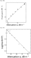
- FIG. 6A the relationships between the FP and the attenuation Alpha of the ball SAW sensor, which are obtained by the static calibration system illustrated in FIG. 4 , are plotted as open circles.
- the calibration of the ball SAW sensor means the determination of the coefficients A, B, C, and D.
- FIG. 6B illustrates the relationship between the attenuation Alpha and the values on the left-hand side of Eq. (3) using data in the low FP range.
- the coefficients C and D can be determined by a least squares fitting.
- a calibration system pertaining to a first embodiment of the present invention encompasses, a first pipe 45a through which background gas flows, a flowmeter 33 installed between the first pipe 45a and a second pipe 45b, an inlet 32 installed between the second pipe 45b and a third pipe 45c, an injector 31 for injecting a constant volume of the calibration gas to the inlet 32, and a quick response moisture sensor 35 installed at downstream of the inlet 32 through the third pipe 45c, which serve as "an introduction pipe”.
- the calibration system pertaining to the first embodiment further encompasses a processing unit 341 connected to the moisture sensor 35, a reference data memory 342 connected to the processing unit 341, and a subject data memory 343 connected to the processing unit 341.
- the moisture sensor 35, the processing unit 341, the reference data memory 342 and the subject data memory 343 implement a moisture analyzer 34.
- the water-vapor generator 36 illustrated in FIG. 1B produces saturated water-vapor in background gases on the head space provided above water, the water is contained in the lower portion of the water-vapor generator 36.
- a thermometer 37 is attached at an upper portion of the water-vapor generator 36.
- the thermometer 37 measures temperature of the background gases saturated with water-vapor.
- the tip of the injector 31 Prior to conducting calibration with the calibration system illustrated in FIG. 1A , the tip of the injector 31 is supposed to be inserted in the water-vapor generator 36. And, by the injector 31, the saturated water-vapor is sampled from the water-vapor generator 36.
- the background gas is introduced into the first pipe 45a illustrated in FIG. 1A , and the background gas flows at a controlled flow rate through the first pipe 45a, as the flow of the background gas is controlled or measured by the flowmeter 33.
- the saturated water-vapor is injected by the injector 31 into inlet 32, the water-vapor is carried through the third pipe 45c to the moisture sensor 35 by diffusion and drifting, and output-responses are obtained by the moisture sensor 35.
- the processing unit 341 include a reference-data obtaining logic-circuit (LCKT) 345, a subject-data obtaining logic-circuit (LCKT) 346, a relationship calculating logic-circuit (LCKT) 347 and control circuit configured to control time sequence of the operations of the reference-data obtaining LCKT 345, the subject-data obtaining LCKT 346 and the relationship calculating LCKT 347.
- LCKT reference-data obtaining logic-circuit
- LCKT subject-data obtaining logic-circuit
- LCKT relationship calculating logic-circuit
- the reference-data obtaining LCKT 345 obtains reference data, which indicate temporal memory of moisture concentrations, after injecting water-vapor with known concentrations into an analyzer of a calibration system.
- the subject-data obtaining LCKT 346 measures subject data indicating temporal variation of output-responses of a subject sensor element of the analyzer under test, the subject data are obtained under same condition with the reference data was obtained.
- the relationship calculating LCKT 347 compares the subject data with the reference data, with same time-duration for obtaining the reference data, the time-duration is measured from a timing at which the water-vapor with the known concentrations is injected. And the relationship calculating LCKT 347 further calculates relationships between the output-responses of the subject sensor element and the known concentrations.
- the reference data memory 342 stores the reference data obtained by reference-data obtaining LCKT 345.
- the subject data memory 343 stores the subject data obtained by the subject-data obtaining LCKT 346.
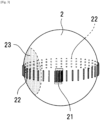
- the moisture sensor 35 is implemented by a ball SAW sensor illustrated in FIG. 3 , and the output-responses vary with time owing to the change in moisture concentration.
- a SAW is excited by the sensor electrode 21 with the specific condition.
- the SAW generates a naturally collimated beam 22 around the piezoelectric ball 2 so that multiple roundtrips along the equator of the ball can be realized. Since the sensitive film 23 coated on the propagation route of the SAW change the viscoelasticity due to adsorption of water, the concentration of moisture can be evaluated by the attenuation Alpha of the SAW.
- the processing unit 341 may be, for example, a central processing unit (CPU) of a computer system.
- the reference-data obtaining LCKT 345, the subject-data obtaining LCKT 346 and the relationship calculating LCKT 347 may be achieved by functional logical circuits arranged in a general-purpose semiconductor integrated circuit.
- the processor may include a programmable logic device (PLD) such as a field-programmable gate array (FPGA).
- PLD programmable logic device
- FPGA field-programmable gate array
- the FPGA is an integrated circuit designed to be configured by a customer or a designer after manufacturing.
- the FPGA configuration is generally specified using a hardware description language (HDL), similar to that used for an application-specific integrated circuit (ASIC).
- HDL hardware description language
- the processing unit 341 may contain the reference-data obtaining LCKT 345, the subject-data obtaining LCKT 346 and the relationship calculating LCKT 347 as an array of programmable logic blocks.
- the electronic hardware of the reference-data obtaining LCKT 345, the subject-data obtaining LCKT 346 and the relationship calculating LCKT 347 can be designed modularly, by creating subcomponents and then higher-level components to instantiate them.
- the output units 349 may be built in the PC, or may be composed integrally with the PC.
- the processing unit 341 is merged with the hybrid IC or module, it is also possible to assemble the processing unit 341 in an inside of the moisture analyzer 34.
- the reference-data obtaining LCKT 345, the subject-data obtaining LCKT 346 and the relationship calculating LCKT 347 may be implemented by architecture of a software program.
- a set of registers, cache memory and a main memory (data memory) as the primary storage, and further a program memory are connected to or built in the processing unit 341 according to the first embodiment of the present invention.
- the primary storage is directly connected to the processing unit 341 of the calibration system embodied by computer system.
- the set of registers are internal to the processing unit 341. Registers contain information that the arithmetic and logic unit needs to carry out the current instruction.
- Registers are technically the fastest of all forms of computer storage, being switching transistors integrated on the CPU's silicon chip, and functioning as electronic "flip-flops".
- Cache memory is a special type of internal memory used by processing unit 341 to increase the performance or "throughput". Some of the information in the main memory is duplicated in the cache memory, which is slightly slower but of much greater capacity than the processor registers, and faster but much smaller than main memory.
- main memory contains the current data and instructions that are currently being run, and is directly connected to the data bus 348a, 348b.
- the arithmetic LCKTs 345, 346 and 347 can very quickly transfer information between the set of register and locations in main storage, also known as a "memory addresses".
- the program memory can be composed of semiconductor memories, magnetic disks, optical disks, magneto-optical disks, magnetic tapes, and the like.
- varieties of input/output data and parameters, which are necessary for calibration, data under computation, and the like can be stored in the data memory such as SRAM.
- the processing unit 341 is configurable of the computer system such as the PC, and accordingly, illustration of the PC is omitted.
- the processing unit 341 may further include input units such as a PC keyboard, a mouse, and a light pen. Specifically, the mouse is clicked for the operator notation displayed on the output units 349, whereby measurement conditions or sensor specifications can be entered.
- a printer device or the like may be provided as well as the output units 349 illustrated in FIG. 1C .
- the effectiveness such that a measurement time as short as ten minutes can be achieved, while ten hours are required for static calibration pertaining to the illustrative examples. Since the calibration system pertaining to the first embodiment implemented by a small number of simple components, it is possible to downsize the scale of the calibration system, and apply the calibration system to on-site calibration. Moreover, since the calibration system pertaining to the first embodiment uses saturated water-vapor as calibration gases, it is easy to prepare high precision calibrated gases in the field without a detailed control.
- the water-vapor generator 36 illustrated in FIG. 1B we use a sampling gas bag for gas analysis, whose inner surface was inactivated, as illustrated in FIG. 7 . After purging the gas bag with nitrogen gas, pure water is injected into the bag and the bag is saturated with water-vapor at room temperature controlled by an air conditioner.
- the injector 31 illustrated in FIGs. 1A and 1B we use a gas-tight syringe, with which we can control the injection volume using the scale of the syringe.
- the saturated water-vapor is extracted from the gas bag using the gas-tight syringe serving as the injector 31, and injected into the inlet 32 provided 170 mm upstream of the ball SAW sensor as the moisture sensor 35 connected to the third pipe 45c.
- the nitrogen gas flow through the first pipe 45a, the second pipe 45b and third pipe 45c is controlled using a mass flow controller as the flow meter 33.
- FIG. 8A illustrates a temporal variation of the FP due to the injection of saturated water-vapor measured using the moisture sensor 35.
- the FP increased immediately after injection and then decreased gradually. The decrease took about ten minutes and is considered to represent a process at which the water adsorbed on the pipe surface was gradually desorbed.
- the expanded view of the peak is illustrated in FIG. 8B .
- the response time taken for 10% to 90% of the FP change from -70 to 10 degrees centigrade was only 0.64 s. Since the response time is less than one second, it can be regarded that the equilibrium between the moisture concentration within the sensitive film and that in the atmosphere is rapidly reached at any instance of the dynamic calibration process pertaining to the first embodiment, which takes ten minutes. This rapid equilibrium is the basis for the validity of the dynamic calibration process pertaining to the first embodiment.
- Step 11 of the procedure illustrated in FIG. 2 the reference-data obtaining LCKT 345 obtains reference data, which indicate temporal variation of moisture concentrations, after injecting water-vapor, which has known concentrations, into an analyzer under test.
- the reference sensor element has been already calibrated by the static calibration method pertaining to the illustrative example, which has been illustrated in FIG. 4 .
- the calibration system may be the dynamic calibration system pertaining to the first embodiment. Then, the calibration system measures the temporal variation of the attenuation Alpha by the injection of saturated water-vapor. The temporal variation of the FP can be obtained by substituting the attenuation Alpha at each time in Eq. (4).
- the reference-data obtaining LCKT 345 stores the obtained reference data into the reference data memory 342.
- the measurement result for the reference data is illustrated in FIGs. 9A and 9B at a background gas flow rate of 10 ml ⁇ min -1 , a saturated water-vapor injection volume of 1 ml, and a room temperature of 21 degrees centigrade.
- the temporal variation of FP was obtained using the calibration curve obtained using Eq. (4), as illustrated in FIG. 9B . Since the rising part of the peak changes rapidly, the rising part is not used for the calibration, and the gradually decreasing part of the curve illustrated in solid curve is used as reference data.
- Step 12 of the procedure illustrated in FIG. 2 the subject-data obtaining LCKT 346 measures subject data indicating temporal variation of output-responses of a subject sensor element of an analyzer under test, the subject data are obtained under same condition with the reference data was obtained.
- the temporal variation of the attenuation Alpha is measured for ten minutes under the same conditions as the condition when the reference data was measured.
- the subject sensor element is implemented by the ball SAW sensor.
- the subject-data obtaining LCKT 346 stores the obtained subject data into the subject data memory 343.
- the attenuation Alpha of a new sensor - -or the subject moisture sensor - - under the same condition as the measurement for the reference data is illustrated by the solid curve in FIG. 10A .
- the relationship calculating LCKT 347 reads out the reference data from the reference data memory 342, and furthermore, the relationship calculating LCKT 347 reads out the subject data from the subject data memory 343. Thereafter, the relationship calculating LCKT 347 compares the subject data with the reference data, with same time-duration for obtaining the reference data, the time-duration is measured from a timing at which the water-vapor with the known concentrations is injected.
- the relationship calculating LCKT 347 further calculates relationships between the output-responses of the subject sensor element and the known concentrations.
- FIG. 10B illustrates the relationship between the attenuation Alpha and the FP in the high concentration range as illustrated by closed circles.
- the RMS error of 2.12 degrees centigrade of the dynamic calibration in the FP range from -59 to -17 degrees centigrade is acceptable for a rough estimate of the sensor condition. Since this error is considered to be the accumulation of errors in the calibration curve obtained using Eq. (4) acquired as the reference data, errors in the amount of injected saturated water-vapor as the calibration gas, and subtle differences in temperature and atmospheric pressure, it can be reduced by improving the system components.
- the calibration program used with the first embodiment of the present invention is stored in a non-transitory computer readable storage medium, and the program memory of the processing unit 341 is caused to read a content recorded in the external recording medium, whereby the calibration program concerned can execute a series of processing of the calibration of the present invention.
- the calibration program which causes the processing unit 341 in the calibration system pertaining to the first embodiment to execute processing for calibration, includes a series of instructions for performing the procedure of the calibration.
- the series of instructions may include instructions to the reference-data obtaining LCKT 345 so that the reference-data obtaining LCKT 345 obtains reference data, which indicate temporal variation of moisture concentrations, after injecting water-vapor with known concentrations into an analyzer of a calibration system.
- the series of instructions still further includes instructions to the relationship calculating LCKT 347 so that compares the subject data with the reference data, with same time-duration for obtaining the reference data, the time-duration is measured from a timing at which the water-vapor with the known concentrations is injected,
- the series of instructions yet still further includes instructions to the relationship calculating LCKT 347 so that the relationship calculating LCKT 347calculates relationships between the output-responses of the subject sensor element and the known concentrations.
- non-transitory computer readable storage medium means such a medium that can record a program.
- the non-transitory computer readable storage medium includes, for example, an external memory device of a computer, a semiconductor memory, a magnetic disk, an optical disk, a magneto-optical disk, a magnetic tape, and the like.
- a flexible disk, a CD-ROM, an MO disk, an open-reel tape and the like are included in the "non-transitory computer readable storage medium".
- a main body of the processing unit 341 can be configured to build therein a flexible disk device and an optical disk device or to cause the flexible disk device and the optical disk device to be externally connected thereto.
- the flexible disk is inserted into the flexible disk drive from an insertion slot thereof, and the CD-ROM is inserted into the optical disk drive from an insertion slot thereof, and both of them are subjected to a predetermined reading operation, whereby the programs stored in these external recording mediums can be installed into the program memory that implements the processing unit 341.
- a predetermined drive device is connected to the processing unit 341, whereby, for example, the ROM and the magnetic tape device can be used as external recording mediums. Furthermore, it is possible to store the calibration program in the program memory via an information processing network such as the Internet in place of using the external recording medium.
- the effectiveness such that a measurement time as short as ten minutes can be achieved, while ten hours are required for static calibration pertaining to the illustrative examples. Therefore, it is possible to apply the calibration program to on-site calibration. Moreover, it is easy to prepare high precision calibrated gases in the field without a detailed control.
- the third pipe 44c is branched into a second branched pipe 44f having a third valve 42, and another branch of the third pipe 44c is connected to a moisture analyzer 34, and therefore the third pipe 44c serve as "an introduction pipe” for the moisture analyzer 34.
- the calibration system pertaining to the second embodiment further encompasses an inlet 32 installed between the first branched pipe 44e and the second branched pipe 44f and an injector 31 for injecting a constant volume of the calibration gas to the inlet 32.
- the background gas is introduced into the first pipe 44a illustrated in FIG. 13 , and the background gas flows at a controlled flow rate through the first pipe 44a, as the flow of the background gas is controlled or measured by the flowmeter 33.
- the saturated water-vapor is injected by the injector 31 into inlet 32, the water-vapor is carried through the third pipe 45c to the moisture analyzer 34 by diffusion and drifting, and output-responses are obtained by the moisture analyzer 34.
- the processing unit 341 encompasses the reference-data obtaining LCKT 345, the subject-data obtaining LCKT 346 and the relationship calculating LCKT 347, which are explained in the first embodiment. Since the calibration system pertaining to the second embodiment embraces simple components, it is possible to downsize the calibration system, and apply the calibration system to on-site calibration. Moreover, since the calibration system pertaining to the second embodiment uses saturated water vapor as calibration gases, it is easy to prepare high precision calibrated gases in the field without a detailed control.
- the effectiveness such that a measurement time as short as ten minutes can be achieved, while ten hours are required for static calibration pertaining to the illustrative examples. Since the calibration system pertaining to the second embodiment implemented by a small number of simple components, it is possible to downsize the scale of the calibration system, and apply the calibration system to on-site calibration. Moreover, since the calibration system pertaining to the second embodiment uses saturated water-vapor as calibration gases, it is easy to prepare high precision calibrated gases in the field without a detailed control.
- FIG. 14A illustrates a temporal variation of moisture concentration calculated from the output-responses of the ball SAW sensor. Each of the output-responses is plotted after shifted by 2000 ppmv.
- FIG. 14B illustrates the result of carrying out similar measurement at each flow rate.
- the dynamic calibration method pertaining to the second embodiment includes the step of the reference-data obtaining LCKT 345 obtains reference data, which indicate temporal variation of moisture concentrations, after injecting water-vapor with known concentrations into an analyzer of a calibration system.
- the dynamic calibration method pertaining to the second embodiment includes the step of the subject-data obtaining LCKT 346 measures subject data indicating temporal variation of responses of a subject sensor element of an analyzer under test, the subject data are obtained under same condition with the reference data was obtained.
- the dynamic calibration method pertaining to the second embodiment includes the step of the relationship calculating LCKT 347 comparers the subject data with the reference data, with same time-duration for obtaining the reference data, the time-duration is measured from a timing at which the water-vapor with the known concentrations is injected. Furthermore, the dynamic calibration method pertaining to the second embodiment includes the step of the relationship calculating LCKT 347 calculates relationships between the responses of the subject sensor element and the known concentrations.
- the dynamic calibration method pertaining to the second embodiment the effectiveness such that a measurement time as short as ten minutes can be achieved, while ten hours are required for static calibration pertaining to the illustrative examples. Therefore, it is possible to apply the dynamic calibration method to on-site calibration. Moreover, since the dynamic calibration method pertaining to the second embodiment uses saturated water-vapor as calibration gases, it is easy to prepare high precision calibrated gases in the field without a detailed control.
- the dynamic calibration method can be executed by the processing unit 341 by a calibration program pertaining to the second embodiment, which is essentially same as the calibration program pertaining to the first embodiment. Therefore, duplicated explanation of the calibration program is omitted. And, a series of instructions for performing the dynamic calibration method shall be stored in a non-transitory computer readable storage medium.
Landscapes
- Chemical & Material Sciences (AREA)
- Life Sciences & Earth Sciences (AREA)
- Health & Medical Sciences (AREA)
- Physics & Mathematics (AREA)
- Analytical Chemistry (AREA)
- General Health & Medical Sciences (AREA)
- Pathology (AREA)
- Immunology (AREA)
- General Physics & Mathematics (AREA)
- Biochemistry (AREA)
- Engineering & Computer Science (AREA)
- Food Science & Technology (AREA)
- Combustion & Propulsion (AREA)
- Medicinal Chemistry (AREA)
- Acoustics & Sound (AREA)
- Signal Processing (AREA)
- Investigating Or Analysing Materials By Optical Means (AREA)
- Investigating Or Analyzing Materials By The Use Of Electric Means (AREA)
- Investigating Or Analyzing Materials By The Use Of Ultrasonic Waves (AREA)
Description
- The present invention related to a system, a method and a program for realizing on-site calibration of a moisture sensor.
- In the process of manufacturing semiconductors and materials that react easily with water, moisture analyzers are used for controlling trace moisture in the process gases as recited in non-patent literature (NPL) 1, and on-site calibration is required to achieve the reliability. Generally, the calibration is performed where the output-response to trace moisture has reached a sufficient equilibrium by maintaining the moisture concentration in the sensor cell for several hours (NPL2).
- However, while such static calibration method enables accurate calibration, it is difficult to apply the static calibration method to on-site calibration because the calibration system is huge and the calibration takes as long as ten hours. In addition, since the earlier calibration system needs a large amount of calibration gases, it is difficult to apply it to processes using special gases for which there is no existing calibration system, or it is not easy to obtain a large amount of calibration gases.
-
US-5502659 discloses an apparatus and a method for calibrating a moisture sensor in a measuring device without removing the measuring device from its operating position, by means of a calibrating sensor coupled by means of a tube to said measuring device so as to expose the calibrating sensor to the same process air as the sensor to be calibrated, wherein a processor compares the data detected by the calibrating sensor to the data detected by the sensor to be calibrated. -
- [NPL 1]: H. Abe et al.: Sens. Actu. A 128, 202-208 (2006).
- [NPL 2]: H. Abe et al.: Sens. Actu. A 136, 723-729 (2007).
- In view of the above problems, an object of the present invention is to provide a system, and a method for calibrating a moisture sensor, which can be performed in a short time and are applicable to on-site calibrations.
- The first aspect of the present invention is defined in
claim 1 and inheres in a system for calibrating a moisture sensor encompassing a processing unit. The processing unit pertaining to the first aspect includes (a) a logic circuit configured to obtain reference data, which indicate temporal variation of moisture concentrations, after injecting water-vapor with known concentrations into an analyzer, (b) a logic circuit configured to measure subject data indicating temporal variation of output-responses of a subject sensor element of the analyzer under test, the subject data are obtained under same condition with the reference data was obtained, (c) a logic circuit configured to compare the subject data with the reference data, with same time-duration for obtaining the reference data, the time-duration is measured from a timing at which the water-vapor with the known concentrations is injected for calculating relationships between the output-responses of the subject sensor element and the known concentrations. - The second aspect of the present invention: is defined in claim 3 and inheres in a method for calibration of a moisture sensor, including (a) obtaining reference data, which indicate temporal variation of moisture concentrations, after injecting water-vapor with known concentrations into an analyzer of a calibration system, (b) measuring subject data indicating temporal variation of output-responses of a subject sensor element of the analyzer under test, the subject data are obtained under same condition with the reference data was obtained, (c) comparing the subject data with the reference data, with same time-duration for obtaining the reference data, the time-duration is measured from a timing at which the water-vapor with the known concentrations is injected, and (d) calculating relationships between the output-responses of the subject sensor element and the known concentrations.
- There is also described herein a non-transitory computer readable storage medium storing a calibration program of system for calibrating a moisture sensor, the calibration program causing a processing unit in the system to execute processing for calibration by a series of instructions for performing calibration. The series of instructions encompasses (a) obtaining reference data, which indicate temporal variation of moisture concentrations, after injecting water-vapor with known concentrations into an analyzer of a calibration system, (b) measuring subject data indicating temporal variation of output-responses of a subject sensor element of the analyzer under test, the subject data are obtained under same condition with the reference data was obtained,(c) comparing the subject data with the reference data, with same time-duration for obtaining the reference data, the time-duration is measured from a timing at which the water-vapor with the known concentrations is injected, and (d) calculating relationships between the output-responses of the subject sensor element and the known concentrations.
- According to the present invention, it is possible to provide the system, and the method for calibrating the moisture sensor, which can be performed in a short time and are applicable to the on-site calibrations.
-
-
fig.1A]FIG. 1A is a conceptual diagram of a dynamic calibration system pertaining to a first embodiment of the present invention; - [
fig.1B]FIG. 1B is a conceptual diagram of saturated water-vapor generator used for the dynamic calibration system illustrated inFIG. 1A ; - [
fig.1C]FIG. 1C is an example of a logical structure of a processing unit implementing the dynamic calibration system illustrated inFIG. 1A ; - [
fig.2]FIG. 2 is an example of a flowchart illustrating a flow of a procedure of a dynamic calibration method pertaining to a first embodiment; - [
fig.3]FIG. 3 is a schematic view of an example of a ball SAW sensor; - [
fig.4]FIG. 4 is a schematic view illustrating an outline of a static calibration system pertaining to an illustrative example not falling under the scope of the present invention; - [
fig.5]FIG. 5 is a diagram illustrating an example of the sensor response when the moisture concentration is changed stepwise using the static calibration system pertaining to the illustrative example; - [
fig.6A]FIG. 6A is a diagram illustrating relationship between output-response as the attenuation Alpha[GREEK] of a ball SAW sensor and moisture concentration equivalent to frost point (FP) obtained by the static calibration system pertaining to the illustrative example; - [
fig.6B]FIG. 6B is a diagram illustrating relationship between the attenuation Alpha and FP in the low concentration range; - [
fig.7]FIG. 7 is a photograph illustrating gas bag for saturated water-vapor generator and gas-tight syringe as injector; - [
fig.8A]FIG. 8A is a diagram illustrating temporal variation of FP measured by ball SAW trace moisture analyzer; - [
fig.8B]FIG. 8B is a diagram enlarging the range of time from 15 to 20 seconds inFIG. 8A ; - [
fig.9A]FIG. 9A is a diagram illustrating a temporal variation of attenuation of SAW after injection of saturated water-vapor. - [
fig.9B]FIG. 9B is a diagram illustrating reference data, that illustrates a temporal variation of FP calculated using calibration curve determined by static calibration; [fig.10A]FIG. 10A is a diagram illustrating reference data and output-response of subject sensor element; - [
fig.10B]FIG. 10B is a diagram illustrating relationship between attenuation Alpha and FP in high concentration range; - [
fig.10C]FIG. 10C is a diagram illustrating relationship between the attenuation Alpha and FP in low concentration range; - [
fig.11]FIG. 11 is a diagram illustrating calibration curves obtained by the dynamic calibration method pertaining to the first embodiment and the static calibration method pertaining to the illustrative example; - [
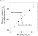
fig. 12] FIG. 12 is a diagram illustrating relationships between set FP and measured FP determined using the dynamic calibration method pertaining to the first embodiment and earlier calibration curves obtained by the static calibration method pertaining to the illustrative example. - [
fig. 13] FIG. 13 is a conceptual diagram of a calibration system pertaining to a second embodiment of the present invention; - [
fig. 14A] FIG. 14A is a diagram illustrating temporal variation of moisture concentration by injection of saturated water vapor obtained by a calibration system pertaining to the second embodiment; and; - [
fig. 14B] FIG. 14B is a diagram illustrating relationship between integrated concentration and flow rate of background gas obtained by the calibration system pertaining to the second embodiment. - Before describing first and second embodiments of the present invention, with reference to
FIGs. 3 ,4 , 5A and 5B, we will introduce an illustrative example for static calibration system, which does not fall under the scope of the present invention but has led to the first and second embodiments of the present invention. - As illustrated in
FIG. 4 , a static calibration system pertaining to the illustrative example includes a first mass flow controller (MFC) 55a, asecond MFC 55b, athird MFC 55c, afourth MFC 55d, afifth MFC 54, a first automatic pressure regulator (APR) 52 and asecond APR 53 so as to implement a wet gas line through thefourth MFC 55d, a first dry gas line through thefirst MFC 55a and a second dry gas line through thethird MFC 55c. The second dry gas line and the wet gas line are connected to implement a first mixed gas line through thesecond MFC 55b. The first dry gas line and the first mixed gas line are connected to implement a second mixed gas line through thefifth MFC 54. The first mixed gas line is branched to an exhaust gas line through thefirst APR 52. - The exhaust gas line and the second mixed gas line are bypassed by a pressure control line through the
second APR 53. The moisture concentration around the calibratingsensor 56 can be changed by controlling the flow ratio between the wet gas line through asaturator 51 and the first and second dry gas lines and the first mixed gas line. Thesaturator 51 is a 0.635 cm (1/4 inch) stainless steel pipe containing pure water and introduces a constant concentration of saturated water-vapor by controlling the temperature with a Peltier device. -
FIG. 5 is an example of the sensor response when the moisture concentration is changed stepwise using the system illustrated inFIG. 4 . The graph illustrated inFIG. 5 illustrates the temporal variation of the attenuation Alpha[GREEK] as the output-response of the ball SAW sensor in ten hours when the moisture concentration evaluated as the frost point (FP) was changed in steps from -76 degrees centigrade to - 17 degrees centigrade. From the data illustrated inFIG. 5 , a calibration curve of the relationship between the FP and the attenuation Alpha can be obtained. While the system illustrated inFIG. 4 is capable of accurate calibration, it is too huge to apply to on-site calibration. - In
FIG. 6A , the relationships between the FP and the attenuation Alpha of the ball SAW sensor, which are obtained by the static calibration system illustrated inFIG. 4 , are plotted as open circles. InFIG. 6A , we found that the relationship indicated as a dotted curve can be expressed as a function of the attenuation Alpha given by
[Math.1]
- That is, the calibration of the ball SAW sensor means the determination of the coefficients A, B, C, and D. When the FP is above -25 degrees centigrade, the FP can be approximated to be almost linear to the attenuation Alpha neglecting the exponential term of Eq. (1) as
[Math.2]
- Therefore, the coefficients A and B can be determined by a least squares fitting of the data in the high concentration range. Furthermore, Eq. (1) can be transformed to
[Math.3]
FIG. 6B illustrates the relationship between the attenuation Alpha and the values on the left-hand side of Eq. (3) using data in the low FP range. - Therefore, the coefficients C and D can be determined by a least squares fitting. By using the coefficients A, B, C, and D, we can obtain the calibration curve for the sensor as
[Math.4]
- Now, embodiments of the present invention will be described below with reference to the drawings. In the descriptions of the following drawings, the same or similar reference numerals are assigned to the same or similar portions. However, the drawings are diagrammatic, and attention should be paid to a fact that the relations between thicknesses and plan view dimensions, the configuration of the apparatus and the like differ from the actual data. Thus, the specific thicknesses and dimensions should be judged by considering the following descriptions.
- Also, even between the mutual drawings, the portions in which the relations and rates between the mutual dimensions are different are naturally included. Also, the embodiment as described below exemplify the apparatuses and methods for embodying the technical ideas of the present invention, and in the technical ideas of the present invention, the materials, shapes, structures, arrangements and the like of configuration parts are not limited to the followings.
- In the following description, the "horizontal" direction or the "vertical" direction is simply assigned for convenience of explanation and does not limit the technical spirit of the present invention. Therefore, for example, when the plane of paper is rotated 90 degrees, the "horizontal" direction is changed to the "vertical" direction and the "vertical" direction is changed to the "horizontal" direction. When the plane of paper is rotated 180 degrees, the "left" side is changed to the "right" side and the "right" side is changed to the "left" side. Therefore, various changes can be added to the technical ideas of the present invention, within the technical scope prescribed by claims.
- As illustrated in
FIG. 1A , a calibration system pertaining to a first embodiment of the present invention encompasses, afirst pipe 45a through which background gas flows, aflowmeter 33 installed between thefirst pipe 45a and asecond pipe 45b, aninlet 32 installed between thesecond pipe 45b and athird pipe 45c, aninjector 31 for injecting a constant volume of the calibration gas to theinlet 32, and a quickresponse moisture sensor 35 installed at downstream of theinlet 32 through thethird pipe 45c, which serve as "an introduction pipe". - As illustrated in
FIG. 1A , the calibration system pertaining to the first embodiment further encompasses aprocessing unit 341 connected to themoisture sensor 35, areference data memory 342 connected to theprocessing unit 341, and asubject data memory 343 connected to theprocessing unit 341. Themoisture sensor 35, theprocessing unit 341, thereference data memory 342 and thesubject data memory 343 implement amoisture analyzer 34. - The water-
vapor generator 36 illustrated inFIG. 1B produces saturated water-vapor in background gases on the head space provided above water, the water is contained in the lower portion of the water-vapor generator 36. At an upper portion of the water-vapor generator 36, athermometer 37 is attached. Thethermometer 37 measures temperature of the background gases saturated with water-vapor. Prior to conducting calibration with the calibration system illustrated inFIG. 1A , the tip of theinjector 31 is supposed to be inserted in the water-vapor generator 36. And, by theinjector 31, the saturated water-vapor is sampled from the water-vapor generator 36. - Thereafter, the background gas is introduced into the
first pipe 45a illustrated inFIG. 1A , and the background gas flows at a controlled flow rate through thefirst pipe 45a, as the flow of the background gas is controlled or measured by theflowmeter 33. And, when the saturated water-vapor is injected by theinjector 31 intoinlet 32, the water-vapor is carried through thethird pipe 45c to themoisture sensor 35 by diffusion and drifting, and output-responses are obtained by themoisture sensor 35. - As illustrated in
FIG. 1C , theprocessing unit 341 include a reference-data obtaining logic-circuit (LCKT) 345, a subject-data obtaining logic-circuit (LCKT) 346, a relationship calculating logic-circuit (LCKT) 347 and control circuit configured to control time sequence of the operations of the reference-data obtaining LCKT 345, the subject-data obtaining LCKT 346 and therelationship calculating LCKT 347. - The reference-
data obtaining LCKT 345 obtains reference data, which indicate temporal memory of moisture concentrations, after injecting water-vapor with known concentrations into an analyzer of a calibration system. The subject-data obtaining LCKT 346 measures subject data indicating temporal variation of output-responses of a subject sensor element of the analyzer under test, the subject data are obtained under same condition with the reference data was obtained. - The
relationship calculating LCKT 347 compares the subject data with the reference data, with same time-duration for obtaining the reference data, the time-duration is measured from a timing at which the water-vapor with the known concentrations is injected. And therelationship calculating LCKT 347 further calculates relationships between the output-responses of the subject sensor element and the known concentrations. Thereference data memory 342 stores the reference data obtained by reference-data obtaining LCKT 345. Thesubject data memory 343 stores the subject data obtained by the subject-data obtaining LCKT 346. - The
moisture sensor 35 is implemented by a ball SAW sensor illustrated inFIG. 3 , and the output-responses vary with time owing to the change in moisture concentration. As illustrated inFIG. 3 , in the ball SAW sensor implementing themoisture sensor 35, a SAW is excited by thesensor electrode 21 with the specific condition. The SAW generates a naturally collimatedbeam 22 around thepiezoelectric ball 2 so that multiple roundtrips along the equator of the ball can be realized. Since thesensitive film 23 coated on the propagation route of the SAW change the viscoelasticity due to adsorption of water, the concentration of moisture can be evaluated by the attenuation Alpha of the SAW. - The
processing unit 341 may be, for example, a central processing unit (CPU) of a computer system. The reference-data obtaining LCKT 345, the subject-data obtaining LCKT 346 and therelationship calculating LCKT 347 may be achieved by functional logical circuits arranged in a general-purpose semiconductor integrated circuit. For example, the processor may include a programmable logic device (PLD) such as a field-programmable gate array (FPGA). - The FPGA is an integrated circuit designed to be configured by a customer or a designer after manufacturing. The FPGA configuration is generally specified using a hardware description language (HDL), similar to that used for an application-specific integrated circuit (ASIC). Similar to the configuration of FPGAs, the
processing unit 341 may contain the reference-data obtaining LCKT 345, the subject-data obtaining LCKT 346 and therelationship calculating LCKT 347 as an array of programmable logic blocks. - That is, like software, the electronic hardware of the reference-
data obtaining LCKT 345, the subject-data obtaining LCKT 346 and therelationship calculating LCKT 347 can be designed modularly, by creating subcomponents and then higher-level components to instantiate them. In a case where theprocessing unit 341 is housed in a PC, theoutput units 349 may be built in the PC, or may be composed integrally with the PC. Meanwhile, in a case where theprocessing unit 341 is merged with the hybrid IC or module, it is also possible to assemble theprocessing unit 341 in an inside of themoisture analyzer 34. Alternatively, the reference-data obtaining LCKT 345, the subject-data obtaining LCKT 346 and therelationship calculating LCKT 347 may be implemented by architecture of a software program. - Though not illustrated, in a similar way to a usual computer system, a set of registers, cache memory and a main memory (data memory) as the primary storage, and further a program memory are connected to or built in the
processing unit 341 according to the first embodiment of the present invention. The primary storage is directly connected to theprocessing unit 341 of the calibration system embodied by computer system. The set of registers are internal to theprocessing unit 341. Registers contain information that the arithmetic and logic unit needs to carry out the current instruction. - Registers are technically the fastest of all forms of computer storage, being switching transistors integrated on the CPU's silicon chip, and functioning as electronic "flip-flops". Cache memory is a special type of internal memory used by processing
unit 341 to increase the performance or "throughput". Some of the information in the main memory is duplicated in the cache memory, which is slightly slower but of much greater capacity than the processor registers, and faster but much smaller than main memory. - Although the illustration is omitted, the main memory contains the current data and instructions that are currently being run, and is directly connected to the
data bus arithmetic LCKTs - The program memory can be composed of semiconductor memories, magnetic disks, optical disks, magneto-optical disks, magnetic tapes, and the like. Hence, a calibration program for drive-controlling the reference-
data obtaining LCKT 345, the subject-data obtaining LCKT 346 and therelationship calculating LCKT 347, which are illustrated inFIG. 1 , and causing theLCKTs - The
processing unit 341 according to the first embodiment of the present invention is configurable of the computer system such as the PC, and accordingly, illustration of the PC is omitted. However, theprocessing unit 341 may further include input units such as a PC keyboard, a mouse, and a light pen. Specifically, the mouse is clicked for the operator notation displayed on theoutput units 349, whereby measurement conditions or sensor specifications can be entered. Moreover, as another output unit, a printer device or the like may be provided as well as theoutput units 349 illustrated inFIG. 1C . - According to the calibration system pertaining to the first embodiment, the effectiveness such that a measurement time as short as ten minutes can be achieved, while ten hours are required for static calibration pertaining to the illustrative examples. Since the calibration system pertaining to the first embodiment implemented by a small number of simple components, it is possible to downsize the scale of the calibration system, and apply the calibration system to on-site calibration. Moreover, since the calibration system pertaining to the first embodiment uses saturated water-vapor as calibration gases, it is easy to prepare high precision calibrated gases in the field without a detailed control.
- As the water-
vapor generator 36 illustrated inFIG. 1B , we use a sampling gas bag for gas analysis, whose inner surface was inactivated, as illustrated inFIG. 7 . After purging the gas bag with nitrogen gas, pure water is injected into the bag and the bag is saturated with water-vapor at room temperature controlled by an air conditioner. As theinjector 31 illustrated inFIGs. 1A and1B , we use a gas-tight syringe, with which we can control the injection volume using the scale of the syringe. The saturated water-vapor is extracted from the gas bag using the gas-tight syringe serving as theinjector 31, and injected into theinlet 32 provided 170 mm upstream of the ball SAW sensor as themoisture sensor 35 connected to thethird pipe 45c. The nitrogen gas flow through thefirst pipe 45a, thesecond pipe 45b andthird pipe 45c is controlled using a mass flow controller as theflow meter 33. - We installed a ball SAW sensor as the
moisture sensor 35 in the system pertaining to the first embodiment, and measured responses by injection of saturated water-vapor. The injection volume was 1 ml and the flow rate of the background gas was 100 ml · min-1. At the measurement, the room temperature was 21.6 degrees centigrade. Response time was evaluated as the time within which a 10% to 90% increase in the FP was observed after the injection of saturated water-vapor. -
FIG. 8A illustrates a temporal variation of the FP due to the injection of saturated water-vapor measured using themoisture sensor 35. The FP increased immediately after injection and then decreased gradually. The decrease took about ten minutes and is considered to represent a process at which the water adsorbed on the pipe surface was gradually desorbed. - The expanded view of the peak is illustrated in
FIG. 8B . The response time taken for 10% to 90% of the FP change from -70 to 10 degrees centigrade was only 0.64 s. Since the response time is less than one second, it can be regarded that the equilibrium between the moisture concentration within the sensitive film and that in the atmosphere is rapidly reached at any instance of the dynamic calibration process pertaining to the first embodiment, which takes ten minutes. This rapid equilibrium is the basis for the validity of the dynamic calibration process pertaining to the first embodiment. - First, to obtain a reference data for a dynamic calibration method pertaining to the first embodiment, we install a reference sensor element implemented by the ball SAW sensor as the
moisture sensor 35 illustrated inFIG. 1A . In Step 11 of the procedure illustrated inFIG. 2 the reference-data obtaining LCKT 345 obtains reference data, which indicate temporal variation of moisture concentrations, after injecting water-vapor, which has known concentrations, into an analyzer under test. - The reference sensor element has been already calibrated by the static calibration method pertaining to the illustrative example, which has been illustrated in
FIG. 4 . The calibration system may be the dynamic calibration system pertaining to the first embodiment. Then, the calibration system measures the temporal variation of the attenuation Alpha by the injection of saturated water-vapor. The temporal variation of the FP can be obtained by substituting the attenuation Alpha at each time in Eq. (4). The reference-data obtaining LCKT 345 stores the obtained reference data into thereference data memory 342. - The measurement result for the reference data is illustrated in
FIGs. 9A and9B at a background gas flow rate of 10 ml · min-1, a saturated water-vapor injection volume of 1 ml, and a room temperature of 21 degrees centigrade. From the temporal variation of the attenuation Alpha after the injection of saturated water-vapor, as illustrated inFIG. 9A , the temporal variation of FP was obtained using the calibration curve obtained using Eq. (4), as illustrated inFIG. 9B . Since the rising part of the peak changes rapidly, the rising part is not used for the calibration, and the gradually decreasing part of the curve illustrated in solid curve is used as reference data. - Next, the reference sensor element is replaced with a subject sensor element to be calibrated, In
Step 12 of the procedure illustrated inFIG. 2 the subject-data obtaining LCKT 346 measures subject data indicating temporal variation of output-responses of a subject sensor element of an analyzer under test, the subject data are obtained under same condition with the reference data was obtained. For example, the temporal variation of the attenuation Alpha is measured for ten minutes under the same conditions as the condition when the reference data was measured. The subject sensor element is implemented by the ball SAW sensor. The subject-data obtaining LCKT 346 stores the obtained subject data into thesubject data memory 343. The attenuation Alpha of a new sensor - -or the subject moisture sensor - - under the same condition as the measurement for the reference data is illustrated by the solid curve inFIG. 10A . - In Step 13 of the procedure illustrated in
FIG. 2 , therelationship calculating LCKT 347 reads out the reference data from thereference data memory 342, and furthermore, therelationship calculating LCKT 347 reads out the subject data from thesubject data memory 343. Thereafter, therelationship calculating LCKT 347 compares the subject data with the reference data, with same time-duration for obtaining the reference data, the time-duration is measured from a timing at which the water-vapor with the known concentrations is injected. - And, furthermore, in Step 14 of the procedure illustrated in
FIG. 2 , therelationship calculating LCKT 347 further calculates relationships between the output-responses of the subject sensor element and the known concentrations. - Using the reference data illustrated by the dotted curve at same time-duration, we obtained the FP at the right ordinate.
FIG. 10B illustrates the relationship between the attenuation Alpha and the FP in the high concentration range as illustrated by closed circles. - Since the relationship illustrated in
FIG. 10B is almost linear, the coefficients of calibration curves A and B were determined to be A = 1.188 and B = -94.41 by a least squares fitting. On the other hand,FIG. 10C illustrates the relationship between the attenuation Alpha and the values obtained by the functional expression represented on the left-hand side of Eq. (3) in the low concentration range as illustrated by open circles. Since the relationship illustrated inFIG. 10C is also linear, coefficients C and D were determined to be C = -0.1983 and D = 11.88 by a least squares fitting. - In
Step 15 of the procedure illustrated inFIG. 2 , therelationship calculating LCKT 347 further defines the calibration data. That is, the calibration curve of the new sensor element obtained by the dynamic calibration method is given by
[Math. 5]
- The calibration curve of the subject sensor element is derived as the relationship between the attenuation Alpha and the FP of the reference data at same time-duration.
- The
relationship calculating LCKT 347 further send the defined calibration data toward theoutput unit 349. Alternatively, the defined calibration data may be stored in a calibration data memory, although the illustration of the calibration data memory is omitted. - Finally, the subject sensor element is calibrated again by the static calibration method. The calibration curve of the same subject sensor element obtained by the static calibration method is given by
[Math. 6]
- In
FIG. 11 , the result of dynamic calibration curve using Eq. (5) is illustrated as a solid curve and the result of static calibration curve using Eq. (6) is illustrated as a dotted curve. These two curves look nearly identical. -
FIG. 12 illustrates the error between the set FP and the measured FP calculated by the substitution of the attenuation Alpha into each calibration curve. The abscissa illustrates the set FP and the ordinate illustrates the measured FP. If there is no error, the measured FP should be plotted on the 45 degrees line illustrated by the dotted line. Open circles illustrate results obtained by the dynamic calibration and closed circles illustrate those obtained by the static calibration. In the FP range from -59 to -17 degrees centigrade, the root-mean-square (RMS) errors of the static and dynamic calibration methods were 0.88 degrees centigrade and 2.12 degrees centigrade, respectively. - The RMS error of 2.12 degrees centigrade of the dynamic calibration in the FP range from -59 to -17 degrees centigrade is acceptable for a rough estimate of the sensor condition. Since this error is considered to be the accumulation of errors in the calibration curve obtained using Eq. (4) acquired as the reference data, errors in the amount of injected saturated water-vapor as the calibration gas, and subtle differences in temperature and atmospheric pressure, it can be reduced by improving the system components.
- According to the dynamic calibration method pertaining to the first embodiment, the effectiveness such that a measurement time as short as ten minutes can be achieved, while ten hours are required for static calibration pertaining to the illustrative examples. Therefore, it is possible to apply the dynamic calibration method to on-site calibration. Moreover, since the dynamic calibration method pertaining to the first embodiment uses saturated water-vapor as calibration gases, it is easy to prepare high precision calibrated gases in the field without a detailed control.
- For example, the calibration program used with the first embodiment of the present invention is stored in a non-transitory computer readable storage medium, and the program memory of the
processing unit 341 is caused to read a content recorded in the external recording medium, whereby the calibration program concerned can execute a series of processing of the calibration of the present invention. - Namely, the calibration program, which causes the
processing unit 341 in the calibration system pertaining to the first embodiment to execute processing for calibration, includes a series of instructions for performing the procedure of the calibration. The series of instructions may include instructions to the reference-data obtaining LCKT 345 so that the reference-data obtaining LCKT 345 obtains reference data, which indicate temporal variation of moisture concentrations, after injecting water-vapor with known concentrations into an analyzer of a calibration system. - The series of instructions further includes instructions to the subject-
data obtaining LCKT 346 so that the subject-data obtaining LCKT 346 measures subject data indicating temporal variation of output-responses of a subject sensor element of an analyzer under test, the subject data are obtained under same condition with the reference data was obtained. - The series of instructions still further includes instructions to the
relationship calculating LCKT 347 so that compares the subject data with the reference data, with same time-duration for obtaining the reference data, the time-duration is measured from a timing at which the water-vapor with the known concentrations is injected, The series of instructions yet still further includes instructions to therelationship calculating LCKT 347 so that the relationship calculating LCKT 347calculates relationships between the output-responses of the subject sensor element and the known concentrations. - Here, the "non-transitory computer readable storage medium" means such a medium that can record a program. The non-transitory computer readable storage medium includes, for example, an external memory device of a computer, a semiconductor memory, a magnetic disk, an optical disk, a magneto-optical disk, a magnetic tape, and the like. Specifically, a flexible disk, a CD-ROM, an MO disk, an open-reel tape and the like are included in the "non-transitory computer readable storage medium".
- For example, a main body of the
processing unit 341 can be configured to build therein a flexible disk device and an optical disk device or to cause the flexible disk device and the optical disk device to be externally connected thereto. The flexible disk is inserted into the flexible disk drive from an insertion slot thereof, and the CD-ROM is inserted into the optical disk drive from an insertion slot thereof, and both of them are subjected to a predetermined reading operation, whereby the programs stored in these external recording mediums can be installed into the program memory that implements theprocessing unit 341. - Moreover, a predetermined drive device is connected to the
processing unit 341, whereby, for example, the ROM and the magnetic tape device can be used as external recording mediums. Furthermore, it is possible to store the calibration program in the program memory via an information processing network such as the Internet in place of using the external recording medium. - According to the calibration program used with the first embodiment, the effectiveness such that a measurement time as short as ten minutes can be achieved, while ten hours are required for static calibration pertaining to the illustrative examples. Therefore, it is possible to apply the calibration program to on-site calibration. Moreover, it is easy to prepare high precision calibrated gases in the field without a detailed control.
- As illustrated in
FIG. 13 , a calibration system pertaining to a second embodiment of the present invention encompasses afirst pipe 44a through which background gas flows, aflowmeter 33 installed between thefirst pipe 44a and asecond pipe 44b. Thesecond pipe 44b is branched into a firstbranched pipe 44e having afirst valve 41, and another branch of thesecond pipe 44b is connected to athird pipe 44c via asecond valve 43. - The
third pipe 44c is branched into a secondbranched pipe 44f having athird valve 42, and another branch of thethird pipe 44c is connected to amoisture analyzer 34, and therefore thethird pipe 44c serve as "an introduction pipe" for themoisture analyzer 34. In the calibration system pertaining to the second embodiment further encompasses aninlet 32 installed between the firstbranched pipe 44e and the secondbranched pipe 44f and aninjector 31 for injecting a constant volume of the calibration gas to theinlet 32. - By branching the pipe at upstream and downstream of the
inlet 32 and switching the flow path using thefirst valve 41, thesecond valve 43 and thethird valve 42, it is possible to adopt configuration which allows replacement and maintenance of theinlet 32 on-line, as themoisture analyzer 34 is installed at downstream of theinlet 32 through thethird pipe 44c. - The water-
vapor generator 36, which was illustrated inFIG. 1B in the explanation of the first embodiment, produces the saturated water-vapor in background gases on the head space of water, the water is contained in the lower portion of the water-vapor generator 36. Prior to conducting calibration with the calibration system illustrated inFIG. 13 , the tip of theinjector 31 is supposed to be inserted in the water-vapor generator 36. And, by theinjector 31, the saturated water-vapor is sampled from the water-vapor generator 36. - Thereafter, the background gas is introduced into the
first pipe 44a illustrated inFIG. 13 , and the background gas flows at a controlled flow rate through thefirst pipe 44a, as the flow of the background gas is controlled or measured by theflowmeter 33. And, when the saturated water-vapor is injected by theinjector 31 intoinlet 32, the water-vapor is carried through thethird pipe 45c to themoisture analyzer 34 by diffusion and drifting, and output-responses are obtained by themoisture analyzer 34. - The
moisture analyzer 34 is implemented by a ball SAW sensor illustrated inFIG. 3 as themoisture sensor 35 of the first embodiment, and the output-responses vary with time owing to the change in moisture concentration. Although the illustration is omitted, similar to the configuration explained in the first embodiment, themoisture analyzer 34 further includes theprocessing unit 341, thereference data memory 342 and thesubject data memory 343. - And, the
processing unit 341 encompasses the reference-data obtaining LCKT 345, the subject-data obtaining LCKT 346 and therelationship calculating LCKT 347, which are explained in the first embodiment. Since the calibration system pertaining to the second embodiment embraces simple components, it is possible to downsize the calibration system, and apply the calibration system to on-site calibration. Moreover, since the calibration system pertaining to the second embodiment uses saturated water vapor as calibration gases, it is easy to prepare high precision calibrated gases in the field without a detailed control. - According to the calibration system pertaining to the second embodiment, the effectiveness such that a measurement time as short as ten minutes can be achieved, while ten hours are required for static calibration pertaining to the illustrative examples. Since the calibration system pertaining to the second embodiment implemented by a small number of simple components, it is possible to downsize the scale of the calibration system, and apply the calibration system to on-site calibration. Moreover, since the calibration system pertaining to the second embodiment uses saturated water-vapor as calibration gases, it is easy to prepare high precision calibrated gases in the field without a detailed control.
- When the injected water concentration is CW and the injection volume is VS, total injected water content VW is given by

- On the other hand, the water vapor injected into the pipe with the background gases passing through at the flow rate F0, diffuses in the flow direction and reaches the sensor while adsorbed to / desorbed from the pipe wall surface, so the moisture concentration around the sensor changes with the time. Since concentration integration IC is the time integral of response curve Cm (t)


- In a condition that the boll SAW sensor illustrated in
FIG. 3 is connected to the calibration system pertaining to the second embodiment, saturated water vapor gas was injected in the calibration system. The flow rate of background gas was changed to 5, 10, 20, 50, and 100 mL/min using a mass flow controller.FIG. 14A illustrates a temporal variation of moisture concentration calculated from the output-responses of the ball SAW sensor. Each of the output-responses is plotted after shifted by 2000 ppmv. The moisture concentration of injected calibration gas was calculated as CW=28100 ppmv from the saturated water vapor pressure at room temperature of 23 degrees centigrade. - When the gas flow rate is 10 mL/min, the total moisture content is 0.0281 mL from Eq. (7), and the theoretical value of concentration integration Ic is 2810 ppm min from Eq. (9). The value of 2810 ppm min is almost equal to Ic=2694 ppm min obtained from the response curve by Eq. (8).
FIG. 14B illustrates the result of carrying out similar measurement at each flow rate. The measured values at all flow rates, which are indicated by open circles, almost agreed with the theoretical values indicated by the solid curve. Consequently, it was illustrated that operation of the calibration system pertaining to the second embodiment follows the theoretical prediction. - Therefore, a similar method for calibration of moisture sensor as the dynamic calibration method pertaining to the first embodiment can be executed. That is, the dynamic calibration method pertaining to the second embodiment includes the step of the reference-
data obtaining LCKT 345 obtains reference data, which indicate temporal variation of moisture concentrations, after injecting water-vapor with known concentrations into an analyzer of a calibration system. And, the dynamic calibration method pertaining to the second embodiment includes the step of the subject-data obtaining LCKT 346 measures subject data indicating temporal variation of responses of a subject sensor element of an analyzer under test, the subject data are obtained under same condition with the reference data was obtained. - Furthermore, the dynamic calibration method pertaining to the second embodiment includes the step of the
relationship calculating LCKT 347 comparers the subject data with the reference data, with same time-duration for obtaining the reference data, the time-duration is measured from a timing at which the water-vapor with the known concentrations is injected. Furthermore, the dynamic calibration method pertaining to the second embodiment includes the step of therelationship calculating LCKT 347 calculates relationships between the responses of the subject sensor element and the known concentrations. - According to the dynamic calibration method pertaining to the second embodiment, the effectiveness such that a measurement time as short as ten minutes can be achieved, while ten hours are required for static calibration pertaining to the illustrative examples. Therefore, it is possible to apply the dynamic calibration method to on-site calibration. Moreover, since the dynamic calibration method pertaining to the second embodiment uses saturated water-vapor as calibration gases, it is easy to prepare high precision calibrated gases in the field without a detailed control.
- According to the calibration program used with the second embodiment, the effectiveness such that a measurement time as short as ten minutes can be achieved, while ten hours are required for static calibration pertaining to the illustrative examples. Therefore, it is possible to apply the calibration program to on-site calibration. Moreover, it is easy to prepare high precision calibrated gases in the field without a detailed control.
- The dynamic calibration method can be executed by the
processing unit 341 by a calibration program pertaining to the second embodiment, which is essentially same as the calibration program pertaining to the first embodiment. Therefore, duplicated explanation of the calibration program is omitted. And, a series of instructions for performing the dynamic calibration method shall be stored in a non-transitory computer readable storage medium. - Various modifications will become possible for those skilled in the art after receiving the teaching of the present disclosure without departing from the scope of the claims. The present invention can be applied to on-site calibration not only of a moisture analyzer using a ball SAW sensor but also of other moisture analyzers.
Claims (3)
- A dynamic calibration system for calibrating a moisture sensor comprising a programmable logic device as a processing unit (341), and an analyzer (34) comprising a moisture sensor (35) configured to accept a subject sensor element, wherein an output of the moisture sensor (35) is connected to the processing unit (341), the processing unit including:a functional logic circuit (345) of said programmable logic device configured to obtain reference data from a calibrated reference sensor element installed as the moisture sensor (35), which indicate temporal variation of moisture concentrations, after injecting water-vapor with known concentrations into the analyzer (34);a functional logic circuit (346) of said programmable logic device configured to obtain subject data indicating temporal variation of output-responses of a subject sensor element to be calibrated installed as the moisture sensor (35) of the analyzer (34, wherein the subject data are obtained under the same condition as the reference data; anda functional logic circuit (347) of said programmable logic device configured to compare the subject data to the reference data with same time-duration measured from a timing at which the water-vapor with the known concentrations is injected for calculating relationships between the output-responses of the subject sensor element and the known concentrations,the system further comprising:an injector (31) configured to inject a constant volume of a calibration gas toan inlet (32) configured to receive a tip of the injector (31) ;a flowmeter (33) configured to control a flow rate of a background gas;a first pipe (44a) for introducing the background gas to the flowmeter (33);a second pipe (44b) connecting the flowmeter (33) with the inlet (32), configured to flow the background gas at a controlled flow rate by the flowmeter (33); anda third pipe (44c) connecting the inlet (32) with the moisture sensor (35), configured to introduce the background gas and the calibration gas into the moisture sensor (35).
- The system of claim 1, wherein the subject sensor element is a ball SAW sensor.
- A method for dynamically calibrating a moisture sensor (35) including:obtaining (S11) reference data from a calibrated reference sensor element, which indicate temporal variation of moisture concentrations, after injecting water-vapor with known concentrations into an analyzer comprising the moisture sensor;obtaining (S12) subject data indicating temporal variation of output-responses of a subject sensor element to be calibrated of the analyzer, wherein the subject data are obtained under the same condition as the reference data; andcomparing (S13) the subject data to the reference data with same time-duration measured from a timing at which the water-vapor with the known concentrations is injected for calculating relationships between the output-responses of the subject sensor element and the known concentrations;receiving a tip of an injector at an inlet for injecting a constant volume of a calibration gas;controlling a flow rate of a background gas by introducing the background gas to a flowmeter;connecting the flowmeter with the inlet, so that the background gas flows at a controlled flow rate by the flowmeter; andconnecting the inlet with the moisture sensor so as to introduce the background gas and the calibration gas into the moisture sensor.
Applications Claiming Priority (2)
| Application Number | Priority Date | Filing Date | Title |
|---|---|---|---|
| US201962815379P | 2019-03-08 | 2019-03-08 | |
| PCT/JP2020/009893 WO2020184496A1 (en) | 2019-03-08 | 2020-03-06 | System, method and program for calibrating moisture sensor |
Publications (3)
| Publication Number | Publication Date |
|---|---|
| EP3887818A1 EP3887818A1 (en) | 2021-10-06 |
| EP3887818A4 EP3887818A4 (en) | 2022-08-10 |
| EP3887818B1 true EP3887818B1 (en) | 2025-02-26 |
Family
ID=72426362
Family Applications (1)
| Application Number | Title | Priority Date | Filing Date |
|---|---|---|---|
| EP20769866.3A Active EP3887818B1 (en) | 2019-03-08 | 2020-03-06 | System, method and program for calibrating moisture sensor |
Country Status (9)
| Country | Link |
|---|---|
| US (1) | US11982659B2 (en) |
| EP (1) | EP3887818B1 (en) |
| JP (1) | JP7109036B2 (en) |
| KR (1) | KR102665593B1 (en) |
| CN (1) | CN113574375B (en) |
| CA (1) | CA3126048C (en) |
| FI (1) | FI3887818T3 (en) |
| TW (1) | TWI749477B (en) |
| WO (1) | WO2020184496A1 (en) |
Families Citing this family (1)
| Publication number | Priority date | Publication date | Assignee | Title |
|---|---|---|---|---|
| DE102020001077A1 (en) * | 2020-02-19 | 2021-08-19 | Bauer Kompressoren Gmbh | Analysis device for gases in a pressurized gas storage tank |
Family Cites Families (51)
| Publication number | Priority date | Publication date | Assignee | Title |
|---|---|---|---|---|
| US3218841A (en) * | 1962-10-10 | 1965-11-23 | Sun Oil Co | Calibrating equipment for moisture indicator |
| US3290920A (en) * | 1964-02-07 | 1966-12-13 | United States Steel Corp | Apparatus for calibrating vapor responsive detectors |
| US3916367A (en) * | 1974-01-22 | 1975-10-28 | Honeywell Inc | Relative humidity sensor |
| US3894419A (en) * | 1974-06-19 | 1975-07-15 | Gulf Research Development Co | Moisture analyzer calibrator |
| JPS5459199A (en) * | 1977-10-20 | 1979-05-12 | Olympus Optical Co Ltd | Ion concentration measuring apparatus |
| US4481596A (en) * | 1981-11-02 | 1984-11-06 | Kaye Instruments Inc. | Method of and apparatus for automatically compensating for variations in output response characteristics of sensors and the like |
| JPH0652261B2 (en) * | 1983-12-06 | 1994-07-06 | 株式会社島津製作所 | Moisture quantitative analysis method by gas chromatography |
| KR900005040Y1 (en) * | 1986-12-02 | 1990-06-05 | 삼성전자 주식회사 | Humidity detecting circuit of electronic range |
| US5343747A (en) * | 1992-06-08 | 1994-09-06 | Jay Rosen | Normalized relative humidity calibration |
| FR2716975A1 (en) * | 1994-03-04 | 1995-09-08 | Coreci | Automatic calibration process for humidity sensor of gas medium e.g. air |
| US5485754A (en) | 1994-04-21 | 1996-01-23 | Intek, Inc. | Apparatus and method for measuring the air flow component and water vapor component of air/water vapor streams flowing under vacuum |
| US5502659A (en) * | 1994-06-06 | 1996-03-26 | Endress+Hauser, Inc. | Method and apparatus for calibrating moisture sensors |
| US5457983A (en) * | 1994-08-23 | 1995-10-17 | Tecnovir International Inc. | Apparatus and method for producing a reference gas |
| JP2642880B2 (en) * | 1994-08-26 | 1997-08-20 | 工業技術院長 | How to calibrate the flow meter |
| US5844138A (en) * | 1997-03-07 | 1998-12-01 | Veris Industries, Inc. | Humidity sensor |
| NZ506493A (en) * | 1997-11-30 | 2003-03-28 | Wissenschaftliche Werkstatt Fu | Measurement of contaminant components in exhaust gas and reduction of excessive contaminant emissions during cold starts and while driving |
| AT3403U1 (en) * | 1998-09-25 | 2000-02-25 | E & E Elektronik Gmbh | DEVICE FOR GENERATING A DEFINED RELATIVE HUMIDITY |
| US6286375B1 (en) * | 1999-04-27 | 2001-09-11 | The United States Of America As Represented By The Secretary Of The Air Force | Apparatus for facilitating headspace sampling |
| RU2189033C2 (en) * | 1999-05-24 | 2002-09-10 | Воронежский государственный университет | Air humidity analyzer |
| US6395560B1 (en) * | 1999-08-02 | 2002-05-28 | Michael Markelov | Headspace sampling apparatus and method |
| JP4029526B2 (en) * | 1999-08-20 | 2008-01-09 | 株式会社島津製作所 | Gas chromatograph |
| US6612149B2 (en) * | 2001-02-15 | 2003-09-02 | Abbott Laboratories | Method and apparatus for calibration of instruments that monitor the concentration of a sterilant in a system |
| DE10203637B4 (en) * | 2002-01-30 | 2004-09-16 | Testo Ag | Method and device for calibrating a moisture sensor |
| JP2004198396A (en) * | 2002-10-23 | 2004-07-15 | Cosmo Instruments Co Ltd | Method for obtaining drift value of leak detector, method for obtaining zero-point fluctuation value, method for obtaining humidity correction coefficient, and method for calibrating leakage detector and the leakage detector |
| JP4291879B2 (en) * | 2003-10-20 | 2009-07-08 | エスペック株式会社 | Saturated gas generator |
| US8364231B2 (en) * | 2006-10-04 | 2013-01-29 | Dexcom, Inc. | Analyte sensor |
| EP1628132B1 (en) * | 2004-08-17 | 2015-01-07 | Sensirion Holding AG | Method and device for calibrating sensors |
| JP2005062199A (en) * | 2004-10-01 | 2005-03-10 | Espec Corp | Calibration method for humidity sensor, and humidity sensor using it |
| DE102005017693A1 (en) * | 2005-04-07 | 2006-10-19 | Festo Ag & Co. | Pneumatic device e.g. valve battery, has mounting device to mount calibration sensors that are arranged nearby stationary sensors of sensor arrangement in mounting state, so that measuring conditions of both sensors are same |
| DE102005059304B3 (en) * | 2005-12-09 | 2007-05-31 | Areva Np Gmbh | Humidity sensor calibrating method for pressurized water nuclear reactor, involves comparing measuring value with actual value given by relationship that is dependant on temperature of reservoir, mass flow and inlet concentration in chamber |
| US7484399B2 (en) * | 2005-12-29 | 2009-02-03 | Microsensor Systems, Inc. | System, apparatus and method for dispensing chemical vapor |
| US7842243B2 (en) * | 2006-02-21 | 2010-11-30 | Sergey Sergeyevich Sarkisov | Chemical sensor with an indicator dye |
| JP4798544B2 (en) | 2006-03-29 | 2011-10-19 | 凸版印刷株式会社 | Dew point meter |
| US7748280B2 (en) * | 2006-07-06 | 2010-07-06 | Ric Investments, Llc | Sidestream gas sampling system with closed sample circuit |
| EP2083266A4 (en) | 2006-11-10 | 2012-02-08 | Univ Tohoku | GAS ANALYZER AND GAS ANALYSIS PROCEDURE |
| ITBO20070036A1 (en) * | 2007-01-23 | 2008-07-24 | Aea Srl | METHOD AND MEASUREMENT DEVICE FOR THE CONCENTRATION OF THE EXHAUST GAS OF A BOILER |
| US8148691B1 (en) * | 2009-08-21 | 2012-04-03 | Jacob Y Wong | Calibration methodology for NDIR dew point sensors |
| EP2726843B1 (en) * | 2011-06-30 | 2016-03-02 | 3M Innovative Properties Company | Systems and methods for detecting an analyte of interest in a sample using filters and microstructured surfaces |
| EP2570807B1 (en) * | 2011-09-16 | 2015-10-28 | Siemens Schweiz AG | Test device for field calibration of a gas sensor |
| US20130160518A1 (en) * | 2011-12-22 | 2013-06-27 | Stmicroelectronics Asia Pacific Pte Ltd. | Relative humidity sensor and method for calibration thereof |
| CA2897133C (en) * | 2013-01-07 | 2018-10-09 | Anpac Bio-Medical Science (Lishui) Co., Ltd. | Apparatus for improved disease detection |
| JP6212815B2 (en) * | 2013-06-21 | 2017-10-18 | ボールウェーブ株式会社 | Moisture concentration sensor and method for measuring moisture concentration |
| CN103591976B (en) * | 2013-11-25 | 2016-08-24 | 北京航天易联科技发展有限公司 | Humidity sensor calibration box |
| WO2015127085A1 (en) * | 2014-02-19 | 2015-08-27 | Ino Therapeutics Llc | Methods for compensating long term sensitivity drift of electrochemical gas sensors exposed to nitric oxide |
| CN104122915B (en) * | 2014-07-19 | 2016-08-17 | 大连民族学院 | A kind of have the warmhouse booth environmental monitoring system with redundant network and the monitoring method thereof of remotely demarcating |
| KR101647228B1 (en) * | 2014-12-24 | 2016-08-10 | 주식회사 포스코 | Humidity measuring apparatus and improvement method for measuring degree thereof |
| CN105021674A (en) * | 2015-07-28 | 2015-11-04 | 国网四川省电力公司电力科学研究院 | Verification method of gas humidity detector |
| US20190033275A1 (en) * | 2017-07-25 | 2019-01-31 | Pulmostics Limited | Temperature variation for sensor array based detection technology |
| US20190195820A1 (en) * | 2017-12-22 | 2019-06-27 | Texas Instruments Incorporated | Relative humidity sensor calibration |
| EP3654028A1 (en) * | 2018-11-14 | 2020-05-20 | MEAS France | Relative humidity sensor device |
| WO2021050294A1 (en) * | 2019-09-10 | 2021-03-18 | Integrated Energy Services Corporation | System and method for assuring building air quality |
-
2020
- 2020-03-06 CA CA3126048A patent/CA3126048C/en active Active
- 2020-03-06 EP EP20769866.3A patent/EP3887818B1/en active Active
- 2020-03-06 JP JP2021544272A patent/JP7109036B2/en active Active
- 2020-03-06 KR KR1020217026976A patent/KR102665593B1/en active Active
- 2020-03-06 CN CN202080017460.9A patent/CN113574375B/en active Active
- 2020-03-06 WO PCT/JP2020/009893 patent/WO2020184496A1/en not_active Ceased
- 2020-03-06 FI FIEP20769866.3T patent/FI3887818T3/en active
- 2020-03-09 TW TW109107631A patent/TWI749477B/en active
-
2021
- 2021-08-09 US US17/397,723 patent/US11982659B2/en active Active
Also Published As
| Publication number | Publication date |
|---|---|
| EP3887818A1 (en) | 2021-10-06 |
| US20210372978A1 (en) | 2021-12-02 |
| KR20210118150A (en) | 2021-09-29 |
| EP3887818A4 (en) | 2022-08-10 |
| CA3126048A1 (en) | 2020-09-17 |
| TWI749477B (en) | 2021-12-11 |
| CN113574375B (en) | 2024-10-25 |
| CA3126048C (en) | 2023-09-12 |
| US11982659B2 (en) | 2024-05-14 |
| KR102665593B1 (en) | 2024-05-14 |
| JP2022520733A (en) | 2022-04-01 |
| JP7109036B2 (en) | 2022-07-29 |
| TW202104893A (en) | 2021-02-01 |
| CN113574375A (en) | 2021-10-29 |
| FI3887818T3 (en) | 2025-03-27 |
| WO2020184496A1 (en) | 2020-09-17 |
Similar Documents
| Publication | Publication Date | Title |
|---|---|---|
| Carey et al. | Multicomponent analysis using an array of piezoelectric crystal sensors | |
| US20110197649A1 (en) | Self-calibrating gas sensor | |
| CN108226387B (en) | Vehicle-mounted exhaust gas analysis system, inspection method thereof, storage medium, and inspection system | |
| US7810376B2 (en) | Mitigation of gas memory effects in gas analysis | |
| JP2019086371A (en) | Gas analyzer calibration method, gas analysis system, and pressure change device | |
| JP2013120058A (en) | Combustion exhaust gas analysis instrument | |
| US11982659B2 (en) | System, method and program for calibrating moisture sensor | |
| JP2541051B2 (en) | Limiting current type oxygen concentration measuring device | |
| CN113933140B (en) | Dynamic gas diluter assessment method and device based on CRDS and standard gas | |
| Vömel et al. | Ozone sonde cell current measurements and implications for observations of near-zero ozone concentrations in the tropical upper troposphere | |
| US2565230A (en) | Gas analysis apparatus | |
| JP2006275606A (en) | Gas detection method and gas detection apparatus | |
| JP2946800B2 (en) | Carbon dioxide measuring device | |
| JP5364957B2 (en) | Trace moisture generator and standard gas generator | |
| JP2001159587A (en) | Gas analyzer | |
| Heinonen | Uncertainty in humidity measurements | |
| CN116235034A (en) | Exhaust gas analysis device, exhaust gas analysis method, and program storage medium for exhaust gas analysis device | |
| EP0343449B1 (en) | Method of and apparatus for determining moisture content in gases | |
| JP2005062056A (en) | Measuring device of exhaust gas flow rate and exhaust gas measuring system using the same | |
| RU2468363C1 (en) | Flow chromatograph | |
| JPH06249765A (en) | Standard gas generator | |
| RU2855362C1 (en) | Method and system for determining the concentration of volatile components of an aqueous solution of wastewater by their traces in the air | |
| CN101131380A (en) | Method and apparatus for detecting trace substance using chromatographic instrument | |
| RU199841U1 (en) | GAS CHROMATOGRAPH | |
| US20240410846A1 (en) | Methods for increasing the accuracy of a humidity sensor |
Legal Events
| Date | Code | Title | Description |
|---|---|---|---|
| STAA | Information on the status of an ep patent application or granted ep patent |
Free format text: STATUS: THE INTERNATIONAL PUBLICATION HAS BEEN MADE |
|
| PUAI | Public reference made under article 153(3) epc to a published international application that has entered the european phase |
Free format text: ORIGINAL CODE: 0009012 |
|
| STAA | Information on the status of an ep patent application or granted ep patent |
Free format text: STATUS: REQUEST FOR EXAMINATION WAS MADE |
|
| 17P | Request for examination filed |
Effective date: 20210629 |
|
| AK | Designated contracting states |
Kind code of ref document: A1 Designated state(s): AL AT BE BG CH CY CZ DE DK EE ES FI FR GB GR HR HU IE IS IT LI LT LU LV MC MK MT NL NO PL PT RO RS SE SI SK SM TR |
|
| DAV | Request for validation of the european patent (deleted) | ||
| DAX | Request for extension of the european patent (deleted) | ||
| A4 | Supplementary search report drawn up and despatched |
Effective date: 20220713 |
|
| RIC1 | Information provided on ipc code assigned before grant |
Ipc: G01N 33/00 20060101ALI20220707BHEP Ipc: G01N 29/44 20060101ALI20220707BHEP Ipc: G01N 29/02 20060101AFI20220707BHEP |
|
| STAA | Information on the status of an ep patent application or granted ep patent |
Free format text: STATUS: EXAMINATION IS IN PROGRESS |
|
| 17Q | First examination report despatched |
Effective date: 20240506 |
|
| GRAP | Despatch of communication of intention to grant a patent |
Free format text: ORIGINAL CODE: EPIDOSNIGR1 |
|
| STAA | Information on the status of an ep patent application or granted ep patent |
Free format text: STATUS: GRANT OF PATENT IS INTENDED |
|
| INTG | Intention to grant announced |
Effective date: 20241009 |
|
| GRAS | Grant fee paid |
Free format text: ORIGINAL CODE: EPIDOSNIGR3 |
|
| GRAA | (expected) grant |
Free format text: ORIGINAL CODE: 0009210 |
|
| STAA | Information on the status of an ep patent application or granted ep patent |
Free format text: STATUS: THE PATENT HAS BEEN GRANTED |
|
| AK | Designated contracting states |
Kind code of ref document: B1 Designated state(s): AL AT BE BG CH CY CZ DE DK EE ES FI FR GB GR HR HU IE IS IT LI LT LU LV MC MK MT NL NO PL PT RO RS SE SI SK SM TR |
|
| REG | Reference to a national code |
Ref country code: GB Ref legal event code: FG4D |
|
| REG | Reference to a national code |
Ref country code: CH Ref legal event code: EP |
|
| REG | Reference to a national code |
Ref country code: DE Ref legal event code: R096 Ref document number: 602020046797 Country of ref document: DE |
|
| REG | Reference to a national code |
Ref country code: IE Ref legal event code: FG4D |
|
| REG | Reference to a national code |
Ref country code: FI Ref legal event code: FGE |
|
| REG | Reference to a national code |
Ref country code: NL Ref legal event code: MP Effective date: 20250226 |
|
| PG25 | Lapsed in a contracting state [announced via postgrant information from national office to epo] |
Ref country code: RS Free format text: LAPSE BECAUSE OF FAILURE TO SUBMIT A TRANSLATION OF THE DESCRIPTION OR TO PAY THE FEE WITHIN THE PRESCRIBED TIME-LIMIT Effective date: 20250526 |
|
| PG25 | Lapsed in a contracting state [announced via postgrant information from national office to epo] |
Ref country code: PL Free format text: LAPSE BECAUSE OF FAILURE TO SUBMIT A TRANSLATION OF THE DESCRIPTION OR TO PAY THE FEE WITHIN THE PRESCRIBED TIME-LIMIT Effective date: 20250226 |
|
| PG25 | Lapsed in a contracting state [announced via postgrant information from national office to epo] |
Ref country code: ES Free format text: LAPSE BECAUSE OF FAILURE TO SUBMIT A TRANSLATION OF THE DESCRIPTION OR TO PAY THE FEE WITHIN THE PRESCRIBED TIME-LIMIT Effective date: 20250226 |
|
| REG | Reference to a national code |
Ref country code: LT Ref legal event code: MG9D |
|
| PG25 | Lapsed in a contracting state [announced via postgrant information from national office to epo] |
Ref country code: NO Free format text: LAPSE BECAUSE OF FAILURE TO SUBMIT A TRANSLATION OF THE DESCRIPTION OR TO PAY THE FEE WITHIN THE PRESCRIBED TIME-LIMIT Effective date: 20250526 Ref country code: IS Free format text: LAPSE BECAUSE OF FAILURE TO SUBMIT A TRANSLATION OF THE DESCRIPTION OR TO PAY THE FEE WITHIN THE PRESCRIBED TIME-LIMIT Effective date: 20250626 |
|
| PG25 | Lapsed in a contracting state [announced via postgrant information from national office to epo] |
Ref country code: NL Free format text: LAPSE BECAUSE OF FAILURE TO SUBMIT A TRANSLATION OF THE DESCRIPTION OR TO PAY THE FEE WITHIN THE PRESCRIBED TIME-LIMIT Effective date: 20250226 |
|
| PG25 | Lapsed in a contracting state [announced via postgrant information from national office to epo] |
Ref country code: HR Free format text: LAPSE BECAUSE OF FAILURE TO SUBMIT A TRANSLATION OF THE DESCRIPTION OR TO PAY THE FEE WITHIN THE PRESCRIBED TIME-LIMIT Effective date: 20250226 |
|
| PG25 | Lapsed in a contracting state [announced via postgrant information from national office to epo] |
Ref country code: PT Free format text: LAPSE BECAUSE OF FAILURE TO SUBMIT A TRANSLATION OF THE DESCRIPTION OR TO PAY THE FEE WITHIN THE PRESCRIBED TIME-LIMIT Effective date: 20250626 Ref country code: LV Free format text: LAPSE BECAUSE OF FAILURE TO SUBMIT A TRANSLATION OF THE DESCRIPTION OR TO PAY THE FEE WITHIN THE PRESCRIBED TIME-LIMIT Effective date: 20250226 |
|
| PG25 | Lapsed in a contracting state [announced via postgrant information from national office to epo] |
Ref country code: GR Free format text: LAPSE BECAUSE OF FAILURE TO SUBMIT A TRANSLATION OF THE DESCRIPTION OR TO PAY THE FEE WITHIN THE PRESCRIBED TIME-LIMIT Effective date: 20250527 Ref country code: BG Free format text: LAPSE BECAUSE OF FAILURE TO SUBMIT A TRANSLATION OF THE DESCRIPTION OR TO PAY THE FEE WITHIN THE PRESCRIBED TIME-LIMIT Effective date: 20250226 |
|
| REG | Reference to a national code |
Ref country code: AT Ref legal event code: MK05 Ref document number: 1771091 Country of ref document: AT Kind code of ref document: T Effective date: 20250226 |
|
| PG25 | Lapsed in a contracting state [announced via postgrant information from national office to epo] |
Ref country code: SE Free format text: LAPSE BECAUSE OF FAILURE TO SUBMIT A TRANSLATION OF THE DESCRIPTION OR TO PAY THE FEE WITHIN THE PRESCRIBED TIME-LIMIT Effective date: 20250226 |
|
| PG25 | Lapsed in a contracting state [announced via postgrant information from national office to epo] |
Ref country code: SM Free format text: LAPSE BECAUSE OF FAILURE TO SUBMIT A TRANSLATION OF THE DESCRIPTION OR TO PAY THE FEE WITHIN THE PRESCRIBED TIME-LIMIT Effective date: 20250226 |
|
| PG25 | Lapsed in a contracting state [announced via postgrant information from national office to epo] |
Ref country code: DK Free format text: LAPSE BECAUSE OF FAILURE TO SUBMIT A TRANSLATION OF THE DESCRIPTION OR TO PAY THE FEE WITHIN THE PRESCRIBED TIME-LIMIT Effective date: 20250226 |
|
| PG25 | Lapsed in a contracting state [announced via postgrant information from national office to epo] |
Ref country code: IT Free format text: LAPSE BECAUSE OF FAILURE TO SUBMIT A TRANSLATION OF THE DESCRIPTION OR TO PAY THE FEE WITHIN THE PRESCRIBED TIME-LIMIT Effective date: 20250226 |
|
| PG25 | Lapsed in a contracting state [announced via postgrant information from national office to epo] |
Ref country code: AT Free format text: LAPSE BECAUSE OF FAILURE TO SUBMIT A TRANSLATION OF THE DESCRIPTION OR TO PAY THE FEE WITHIN THE PRESCRIBED TIME-LIMIT Effective date: 20250226 |
|
| PG25 | Lapsed in a contracting state [announced via postgrant information from national office to epo] |
Ref country code: EE Free format text: LAPSE BECAUSE OF FAILURE TO SUBMIT A TRANSLATION OF THE DESCRIPTION OR TO PAY THE FEE WITHIN THE PRESCRIBED TIME-LIMIT Effective date: 20250226 Ref country code: CZ Free format text: LAPSE BECAUSE OF FAILURE TO SUBMIT A TRANSLATION OF THE DESCRIPTION OR TO PAY THE FEE WITHIN THE PRESCRIBED TIME-LIMIT Effective date: 20250226 |
|
| REG | Reference to a national code |
Ref country code: CH Ref legal event code: H13 Free format text: ST27 STATUS EVENT CODE: U-0-0-H10-H13 (AS PROVIDED BY THE NATIONAL OFFICE) Effective date: 20251023 |
|
| PG25 | Lapsed in a contracting state [announced via postgrant information from national office to epo] |
Ref country code: RO Free format text: LAPSE BECAUSE OF FAILURE TO SUBMIT A TRANSLATION OF THE DESCRIPTION OR TO PAY THE FEE WITHIN THE PRESCRIBED TIME-LIMIT Effective date: 20250226 |
|
| PG25 | Lapsed in a contracting state [announced via postgrant information from national office to epo] |
Ref country code: SK Free format text: LAPSE BECAUSE OF FAILURE TO SUBMIT A TRANSLATION OF THE DESCRIPTION OR TO PAY THE FEE WITHIN THE PRESCRIBED TIME-LIMIT Effective date: 20250226 |
|
| PG25 | Lapsed in a contracting state [announced via postgrant information from national office to epo] |
Ref country code: LU Free format text: LAPSE BECAUSE OF NON-PAYMENT OF DUE FEES Effective date: 20250306 |
|
| REG | Reference to a national code |
Ref country code: DE Ref legal event code: R097 Ref document number: 602020046797 Country of ref document: DE |
|
| REG | Reference to a national code |
Ref country code: BE Ref legal event code: MM Effective date: 20250331 |
|
| PG25 | Lapsed in a contracting state [announced via postgrant information from national office to epo] |
Ref country code: MC Free format text: LAPSE BECAUSE OF FAILURE TO SUBMIT A TRANSLATION OF THE DESCRIPTION OR TO PAY THE FEE WITHIN THE PRESCRIBED TIME-LIMIT Effective date: 20250226 |
|
| PLBE | No opposition filed within time limit |
Free format text: ORIGINAL CODE: 0009261 |
|
| STAA | Information on the status of an ep patent application or granted ep patent |
Free format text: STATUS: NO OPPOSITION FILED WITHIN TIME LIMIT |
|
| PG25 | Lapsed in a contracting state [announced via postgrant information from national office to epo] |
Ref country code: FR Free format text: LAPSE BECAUSE OF NON-PAYMENT OF DUE FEES Effective date: 20250426 |
|
| PG25 | Lapsed in a contracting state [announced via postgrant information from national office to epo] |
Ref country code: BE Free format text: LAPSE BECAUSE OF NON-PAYMENT OF DUE FEES Effective date: 20250331 |
|
| PG25 | Lapsed in a contracting state [announced via postgrant information from national office to epo] |
Ref country code: CH Free format text: LAPSE BECAUSE OF NON-PAYMENT OF DUE FEES Effective date: 20250331 |
|
| PG25 | Lapsed in a contracting state [announced via postgrant information from national office to epo] |
Ref country code: IE Free format text: LAPSE BECAUSE OF NON-PAYMENT OF DUE FEES Effective date: 20250306 |
|
| 26N | No opposition filed |
Effective date: 20251127 |
|
| PGFP | Annual fee paid to national office [announced via postgrant information from national office to epo] |
Ref country code: GB Payment date: 20260323 Year of fee payment: 7 |
|
| PGFP | Annual fee paid to national office [announced via postgrant information from national office to epo] |
Ref country code: DE Payment date: 20260323 Year of fee payment: 7 |
|
| PGFP | Annual fee paid to national office [announced via postgrant information from national office to epo] |
Ref country code: FI Payment date: 20260323 Year of fee payment: 7 |