EP3887745B1 - Schalldämpfer für eine waffe - Google Patents
Schalldämpfer für eine waffe Download PDFInfo
- Publication number
- EP3887745B1 EP3887745B1 EP19891577.9A EP19891577A EP3887745B1 EP 3887745 B1 EP3887745 B1 EP 3887745B1 EP 19891577 A EP19891577 A EP 19891577A EP 3887745 B1 EP3887745 B1 EP 3887745B1
- Authority
- EP
- European Patent Office
- Prior art keywords
- chamber
- suppressor
- flow
- gases
- baffle
- Prior art date
- Legal status (The legal status is an assumption and is not a legal conclusion. Google has not performed a legal analysis and makes no representation as to the accuracy of the status listed.)
- Active
Links
Images


Classifications
-
- F—MECHANICAL ENGINEERING; LIGHTING; HEATING; WEAPONS; BLASTING
- F41—WEAPONS
- F41A—FUNCTIONAL FEATURES OR DETAILS COMMON TO BOTH SMALLARMS AND ORDNANCE, e.g. CANNONS; MOUNTINGS FOR SMALLARMS OR ORDNANCE
- F41A21/00—Barrels; Gun tubes; Muzzle attachments; Barrel mounting means
- F41A21/30—Silencers
-
- F—MECHANICAL ENGINEERING; LIGHTING; HEATING; WEAPONS; BLASTING
- F41—WEAPONS
- F41C—SMALLARMS, e.g. PISTOLS, RIFLES; ACCESSORIES THEREFOR
- F41C27/00—Accessories; Details or attachments not otherwise provided for
-
- F—MECHANICAL ENGINEERING; LIGHTING; HEATING; WEAPONS; BLASTING
- F41—WEAPONS
- F41A—FUNCTIONAL FEATURES OR DETAILS COMMON TO BOTH SMALLARMS AND ORDNANCE, e.g. CANNONS; MOUNTINGS FOR SMALLARMS OR ORDNANCE
- F41A21/00—Barrels; Gun tubes; Muzzle attachments; Barrel mounting means
- F41A21/32—Muzzle attachments or glands
Definitions
- the present invention relates to suppressors for guns.
- a gun is a device that uses the expansion of a gas to propel a projectile.
- the gas can take several forms, such as compressed air stored in a canister attached to the gun.
- Firearms are a sub-type of gun that use the expansion of a gas created by combustion to propel a projectile.
- a combustible material such as gun powder is stored within a projectile cartridge.
- a firing mechanism in the firearm is used to ignite the combustible material. The combustion process creates the gas. The heat of combustion increases the temperature of the gas, which causes it to expand to an area of lower pressure.
- the primary exit from the firearm is through the open end of the gun barrel.
- the gas expands towards the open end of the firearm barrel. That expansion is transferred to the projectile, propelling it out from the firearm barrel.
- the creation and expansion of the gas is a fast process. Accordingly, the projectile exits the firearm barrel at high speed.
- the generation and expansion of the gas also creates significant noise in the form of a blast wave.
- blast wave is undesirable for a number of reasons. Firstly, the blast wave creates a loud noise, which can damage a person's ears. Repeated exposure to blast waves will result in hearing loss. Secondly, the noise of the blast wave makes the use of guns unpleasant. That may be relevant where people use guns for recreational purposes such as target shooting. Thirdly, the blast wave can create a safety hazard. For instance, police may use guns around volatile gases such as those present in meth labs, or the flash and noise may attract enemy fire.
- suppressors or silencers are used to control the gas expansion and thereby minimise the adverse effects it creates.
- suppressor is a device which is configured to be attached to the end of a gun barrel. These devices include an inlet and an outlet, and a connecting passageway. In-use a projectile fired by the gun passes through the inlet, along the passageway, exiting the suppressor via the outlet.
- suppressors include a series of internal baffles which define chambers within the suppressor.
- the gas generated during firing of the projectile is able to expand into the chambers.
- the chambers are arranged such that a first chamber is comparatively larger than the volume of the gun barrel. Accordingly, the first chamber provides a large volume into which the gas may expand.
- the gas can subsequently expand into adjacent chambers in the suppressor.
- the chambers facilitate a gradual expansion of the gas. As a result, the expansion of the gas is slower than were the suppressor not used, which minimises the noise created by the blast wave.
- baffle structures and configurations in gun suppressors There are numerous arrangements for baffle structures and configurations in gun suppressors. Many of these are successful in reducing the noise on firing of a gun. However, no known suppressor yet completely removes all noise created on firing of a gun. It would be advantageous to have a gun suppressor having a baffle structure which may further reduce the noise created on firing of a gun in comparison to existing suppressors.
- a suppressor creates a sustained and increased pressure within the system of a firearm longer than the firearm system was designed for.
- An increased back pressure in the firearm has been recognized as a suppressor drawback for a hundred years.
- the sustained increased pressure can result in several drawbacks.
- the sustained increased back pressure can cause an increase in firearm bolt velocity.
- the increase pressure within the firearm system causes the firearm bolt to move to the rear of the firearm system faster than it was designed, potentially causing a violent extraction of the projectile cartridge from the chamber of the firearm.
- the projectile cartridge due to being thrown violently rearwards, can get jammed in the chamber of the firearm.
- the pressure within the firearm system has not yet reduced to normal levels via the muzzle of the firearm, which can cause a blowback of higher pressure gases together with combustion debris into or towards the face of the user.
- Improved sound suppression can be achieved by increasing the volume of the suppressor, for example by increasing the diameter and/or length of the suppressor.
- the diameter of a suppressor in order for a user to sight the firearm at a target.
- An increased length essentially lengthens the barrel of the firearm, making the firearm more cumbersome to use. There is therefore a tradeoff between suppressor volume/length and suppressor effectiveness.
- Dual flow suppressors have been designed to improve suppression while also attempting to reduce back pressure.
- a dual flow suppressor is a suppressor in which the flow of gases through the suppressor are split into two parallel flow paths through the suppressor.
- An early example of a suppressor with an inner flow path and an outer flow path is provided by US Patent No. 1 ,017,003 .
- a problem with dual flow suppressors is that most (if not substantially all) of the flow of gases through the suppressor will follow the larger projectile pathway through the suppressor with little flow via the outer parallel flow path. The outer flow path therefore does not result in a significant improvement in suppressor performance for a given suppressor volume.
- the inventor considers that the flow of gases from the firearm system and sound suppression of those gases must occur within the time period between the moment the gases begin entering the suppressor after the firearm has been fired and the moment the firearm bolt starts to open to release the projectile cartridge from the chamber of the firearm.
- This time period from gases entering the suppressor to the bolt starting to open generally occurs within about 1 millisecond for semi and fully automatic firearms.
- the time period for a full cycle of firing, bolt opening and ejecting the spent cartridge, and loading and firing the next cartridge is in the order of about 100milli seconds for a fully automatic firearm.
- the time period to supress the gases is about 1% of a firing cycle for a fully automatic firearm.
- Inefficient suppressors can allow the gases to exit the firearm system quickly but with a correspondingly poor level of sound suppression.
- the inventor believes the flow of gases through the suppressor must be split into parallel flow paths and with the pressure between those flow paths balanced and/or the velocity of the gases through those flow paths matched. Balanced pressure between the parallel flow paths means there is no or negligible pressure difference between the flow paths along the length of the flow path.
- the gases flow from each of the flow paths exits the suppressor at the same time, or in other words, the velocity of the gases through each flow path is approximately the same. This results in a dual or outer flow path that is effective in the suppression of sound.
- the invention is a suppressor for a firearm as defined by the appended claims
- a volume of gases entering the suppressor upon firing the firearm is divided at the blast chamber into a first volume to flow into the outer chamber and a second volume to flow into the inner chamber, and the suppressor is configured so that the first volume of gases that flows into the outer chamber and the second volume of gases that flows into the inner chamber exhaust from the suppressor at substantially the same time.
- the suppressor comprises equalisation holes in the tubular inner wall to allow gases flow from the inner flow path to the parallel outer flow path as gases created by firing the firearm flow and/or expand through the suppressor from the blast chamber to the outlet via the inner flow path and the at least one gases outlet aperture via the parallel outer flow path.
- the equalisation holes in the tubular inner wall are spaced apart along the length of the suppressor.
- the suppressor comprises a first baffle.
- the blast chamber is defined by a portion of the tubular side wall and the first baffle and the inlet end of the suppressor.
- the first baffle comprises an aperture aligned with the inlet and the outlet on the projectile pathway, the aperture forming an inlet to the inner chamber.
- the first baffle is symmetrical.
- the first baffle comprises baffle side wall approximately shaped in the form of a truncated cone with a narrow end oriented towards the inlet end of the suppressor.
- the suppressor comprises one or more inner baffles spaced apart along the length of the inner chamber, each inner baffle extending from the inner wall and comprising a projectile aperture aligned with the inlet and the outlet on the projectile pathway, the inner baffle(s) dividing the inner chamber into a series of inner sub-chambers.
- the suppressor comprises at least one chamber equalisation hole through the tubular inner wall within each sub chamber of the inner chamber.
- one or more sub chambers of the inner chamber comprises at least one equalisation hole adjacent a forward end of the sub-chamber.
- one or more sub chambers of the inner chamber comprises a plurality of equalisation holes spaced circumferentially apart around the tubular inner wall.
- one or more sub chambers of the inner chamber comprises a least four equalisation holes spaced equidistant apart around the circumference of the inner wall.
- one or more of the inner baffles comprises an asymmetric baffle side wall comprising a long side and a diametrically opposite short side.
- the baffle side wall may be approximately shaped in the form of a truncated asymmetric cone with a narrow end oriented towards the inlet end of the suppressor.
- one or more sub chambers of the inner chamber comprises an equalisation hole in angular alignment with the short side of the baffle side wall.
- One or more sub chambers of the inner chamber may additionally or alternatively comprise an equalisation hole in angular alignment with a long side of the baffle side wall.
- one or more sub chambers comprises a plurality of holes arranged together in a group in angular alignment or proximity with a short side of the baffle side wall.
- one or more of the inner baffles has the projectile aperture arranged at an angle to a plane perpendicular to the projectile passageway.
- one or more of the inner baffles comprises an asymmetric baffle side wall comprising a long side and a diametrically opposite short side, and wherein the projectile aperture is angled towards a long side of the baffle side wall.
- one or more of the inner baffles comprises a cowling extending rearwards from the baffle side wall and/or a surface or rim around the projectile aperture, the cowling shaped to direct a portion of a flow of gases at the projectile aperture in a direction orthogonal to the projectile passageway and/or create an area of increased pressure that extents at least partway across the projectile aperture.
- an inner surface of the cowling facing towards the projectile aperture is concave and curves through approximately 90 degrees from parallel to a longitudinal axis of the suppressor at a rear end of the cowling to perpendicular to the longitudinal axis at a forward end of the cowling.
- the baffle side wall extends radially outwards and in a forward direction of the suppressor from adjacent the projectile aperture
- the inner baffle comprises a secondary baffle wall extending radially outwards and in a rearward direction of the suppressor from a rear end of the cowling.
- the secondary side wall extends for a portion of the circumference of the projectile aperture.
- the outer chamber increases in volume in a forward direction through the suppressor and/or the inner chamber decreases in volume in a forward direction through the suppressor.
- the tubular side wall may be cylindrical, and the tubular inner wall may be part conical so that the diameter of the inner chamber decreases in a forward direction through the suppressor with a corresponding increase in radial width of the outer chamber in the forward direction through the suppressor.
- the suppressor comprises one or more outer baffles spaced apart along the length of the outer chamber dividing the inner chamber into a series of outer sub-chambers.
- one or more of the outer baffles extend between the tubular side wall and the tubular inner wall.
- the suppressor comprises an outer chamber inlet to receive a flow of gases from the blast chamber into the outer chamber, and wherein a resistance to flow of the inlet is greater than the resistance to flow of a first outer baffle within the outer chamber.
- a resistance to flow of a second outer baffle within the outer chamber is less than a resistance to flow of the first outer baffle, the second baffle located nearer to the exit end of the suppressor than the first baffle.
- one or more rearward outer baffles have a higher resistance to flow than one or more forward outer baffles.
- At least one or more outer baffles imparts a whirling motion circumferentially around the outer chamber.
- At least two outer baffles each imparts a whirling motion circumferentially around the outer chamber, a first whirl baffle imparting a whirling motion in a first circumferential direction and a second whirl baffle imparting a whirling motion circumferentially around the outer chamber in a second circumferential direction.
- the suppressor comprises an outer chamber inlet baffle comprising a plurality of holes providing an outer chamber inlet.
- a flow area of an inlet to the outer chamber is greater than or equal to a flow area of an inlet to the inner chamber.
- a suppressor for a firearm comprising:
- the suppressor comprises a tubular inner wall separating the inner and outer chambers and equalization holes in the tubular inner wall to allow gases flow between the inner and outer parallel flow paths.
- the suppressor comprises a blast chamber that provides an entry chamber common to both the inner and outer parallel flow paths.
- a suppressor for a firearm comprising:
- the second and third aspects of the present invention may comprise any one or more features described above in relation to the first aspect of the present invention.
- ⁇ parallel flow paths means flow in two or more flow paths is in the same direction, as opposed to counter flow where the flow in one path is in the opposite direction to the flow in another flow path.
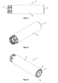
- Figures 1 to 13 show a suppressor according to one embodiment of the present invention.
- the illustrated suppressor 1 is manufactured using a selective metal melting technique such as laser metal sintering ("LMS") techniques as discussed in the Applicant's earlier patent application US serial number 14/138,441 granted as US Patent No. 9,102,010 .
- LMS laser metal sintering
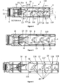
- the suppressor comprises an inner or central chamber 10 and an outer chamber 110.
- the inner and outer chambers provide for two parallel flow paths.
- the inner and outer chambers are concentric.
- each flow path is in the same direction, i.e. the flow in each path is generally in a forward direction, from the inlet or aft or rear end 2 of the suppressor 1 to the exit or fore or front end 3 of the suppressor 1.
- the suppressor is without a counter-flow flow path, i.e. a path in which gases must flow in a rearwards direction through the suppressor before exiting from the exit end of the suppressor.
- Structures such as baffles, described in more detail below, within each flow path 10, 110 are not designed to reverse the flow back towards the inlet end 2.
- the gases flow throughout each chamber 10, 110 is generally in the forward direction or at least has a forward component, towards the exit end 3 of the suppressor.
- the suppressor comprises a fitting 4 to attach the suppressor to the end of a barrel of a firearm.
- the fitting 4 is a screw thread that is a portion of a quick disconnect coupling for attaching to the firearm barrel.
- Any known fitting may be provided at or towards the inlet end of the suppressor, such as a screw thread to attach directly to the barrel, a Quick Disconnect (QD) fitting/coupling, or other fitting or portion of a fitting or connector.
- QD Quick Disconnect
- the fitting attaches the suppressor to a barrel, the fitting essentially provides an inlet 11 to the suppressor.
- the suppressor has an end wall 5 at the exit end of the suppressor, and a tubular side wall 6 extending between the end wall 5 and the inlet end 2 of the suppressor to define an outer shell or can.
- the inner and outer chambers are divided by a tubular inner or intermediate wall 7 radially within the tubular side wall.
- the tubular side wall 6 and/or tubular inner wall 7 may be cylindrical or otherwise shaped, for example a triangular, octagonal, or other polygon shaped tubular wall.
- the end wall 5 has a plurality of holes 8 for gases to flow from the outer chamber of the suppressor and a projectile aperture 9, the holes 8 providing an outlet from the outer chamber 110.
- the outlets 8 are radially outside of the projectile aperture 9.
- the projectile aperture 9 in the end wall is the only outlet from the central chamber 10 of the suppressor 1.
- the plurality of holes 8 in the end wall are spaced circumferentially apart. In the illustrated embodiment the combined area of the holes 8 is approximately equal to or is greater than the area of the projectile aperture 9.
- a blast chamber 14 is provided within the outer shell adjacent the inlet end 2 of the suppressor 1.
- the blast chamber 14 is defined or bounded by a portion of the side wall 6 of the suppressor, the inlet end 2 and/or fitting 4 of the suppressor, and a first baffle 15 of the suppressor.
- fins are provided to the inside of the blast chamber. These fins are structural elements and are not provided as baffles to work on the gases created by the blast from the projectile cartridge.
- the fins may include holes as shown to allow for a maximum gases flow from the firearm into the suppressor.
- the blast chamber is intended to provide an unrestricted chamber to receive gases from the firearm with minimal flow restriction.
- the first baffle 15 provides an inlet end wall to the central chamber 10 and divides the central chamber 10 from the blast chamber 14.
- the inner chamber 10 is defined or bound by the tubular inner wall 7, the end wall 5 and the first baffle 15.
- the first baffle is provided with a projectile aperture 13 that is aligned with the inlet 11 to the suppressor and the exit aperture 9 in the end wall 5, to provide a projectile passageway through the suppressor.
- the projectile aperture 13 in the first baffle 15 forms an inlet to the central chamber 10.
- the first baffle 15 is preferably without other apertures, such that the projectile aperture 13 is the only aperture directly between the central chamber 10 and the blast chamber 14.
- An outer chamber inlet baffle 115 at an inlet end of the outer chamber 110 divides the blast chamber 14 from the outer chamber 110.
- the outer chamber 110 is defined or bounded by the outer wall 6, the inner wall 7, the inlet baffle 115 and the end wall 8.
- the term 'inlet baffle' used to describe this feature of the suppressor is used in a general sense.
- the 'inlet baffle' includes many apertures 113 ( Figure 7 ) that in combination provide an inlet to the outer chamber 110.
- the 'inlet baffle' may be provided by a number of spaced apart fins or spokes extending between the side wall and the inner wall/first baffle.
- the inlet baffle 115 is positioned in line with the outer perimeter of the first baffle to structurally support the outer perimeter of the first baffle 15 from the side wall 6.
- the inner chamber defines an inner flow path and the outer chamber defines a parallel outer flow path.
- the blast chamber 14 forms an entry chamber common to both the inner flow path 10 and the parallel outer flow path 110.
- the blast chamber 14 fills with pressurised gases and the first baffle 15 acts on the gases to separate the gases into the two parallel flows, an inner flow through the inner chamber 10 via the aperture 13 of the first baffle 15, and an outer flow through the outer chamber 110 via the inlet 113 to the outer chamber 110.
- the outer chamber is without a counter-flow gases flow path in an opposite rearward direction between the blast chamber and the at least one gases outlet.
- the flow through the outer chamber is in the forward direction from the blast chamber to the outlet 8, without flowing via a counter flow path.
- the inner chamber is also without a counter-flow flow path.
- the first baffle 15 preferably directs flow to the outer chamber 110.
- the first baffle is preferably symmetrical as shown.
- the first baffle comprises a side wall 15a that is generally or approximately shaped in the form of a truncated cone or approximately frusto-conical.
- the projectile aperture 13 is located at the narrow end of the frustum of the cone shape.
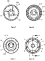
- the first baffle may include a surface 15b ( Figures 7 and 11 ) orthogonal to the longitudinal axis of the suppressor (and projectile passageway) with the projectile aperture 13 formed in or through the orthogonal surface.
- the surface 15b may be annular with an outer diameter concentric with the projectile aperture 13.
- the baffle 15 may include a neck section 15c extending from the frusto-conical side wall 15a, with the neck section 15c forming part of the orthogonal surface through which the aperture 13 is provided.
- a symmetrical baffle also contributes to projectile stability as the projectile enters the blast chamber under high pressure.
- the gases As the gases expand and move forward from the blast chamber 14 the gases hit the rearward facing surfaces of the first baffle 15 and are deflected radially outwards.
- the gases act on the first baffle as the projectile fired from the firearm enters the projectile aperture 13, effectively blocking the aperture 13 such that the gases pass over the rearward surfaces of the baffle 15 and enter the outer chamber 110 via inlet 113.
- the projectile quickly 'outruns' the gases, passing out of the suppressor while the gases are still expanding within the blast chamber to enter into the central and outer chambers.
- the combined area of the holes 113 of the inlet baffle 115 to the outer chamber 110 is the same as or greater than the area of the projectile aperture 13 of the first baffle 15, to promote gases flow from the blast chamber 14 into the outer chamber 110, with gases also passing into the central chamber 10.
- the suppressor comprises one or more inner baffles 16, 17, 18 spaced apart along the length of the central chamber 10.
- the baffles 16, 17, 18 separate the central chamber 10 into a series of sub chambers 19, 20, 21, 22.
- Each sub chamber is defined by a baffle at its inlet end, the inner wall 7 and a baffle at its exit end or for the last chamber 22 in the series of sub chambers, the end wall 5.
- Each baffle includes a projectile aperture 13, with the projectile apertures aligned to provide a projectile passageway through the suppressor.
- Each baffle 16, 17, 18 extends from the inner wall 7.
- baffles 16, 17, 18 within the central chamber 10 'aggressively' work the gases as the gases move forward through the central chamber 10. Effective sound suppression is achieved by aggressively working the gases to impede the progress of the gases expanding and flowing through the suppressor 1.
- the suppressor comprises three baffles 16, 17, 18 to divide the central chamber 10 into four sub-chambers 19 - 22 in series.
- the suppressor may comprise one, two or more than three baffles.
- each baffle 16, 17, 18 within the central chamber 10 comprises an asymmetric sidewall (16a Figure 12 ) extending radially inwards from the inner wall 7.
- the baffle side wall extends radially outwards and in a forward direction of the suppressor from adjacent the projectile aperture i.e. from the orthogonal surface adjacent the projectile aperture, to the inside of the inner tubular wall.
- the side wall 16a is approximately an asymmetric truncated conical sidewall.
- a base or wide end of the asymmetric truncated cone section is formed with the inner wall 7 at an angle to a plane perpendicular to the longitudinal axis of the suppressor to place the projectile aperture 13 in alignment with the projectile passageway through the suppressor.
- Each baffle is arranged with a narrow end of the frustum of the cone shape towards the rear or inlet end of the suppressor, with the narrow end and projectile aperture 13 also at an angle to a plane perpendicular to the longitudinal axis of the suppressor.
- Each baffle therefore may be described as a slanted or tilted baffle, being arranged non-perpendicular to the central axis of the suppressor or the projectile passageway.
- the narrow end of the cone frustum is angled towards the long side 16a(i) of the frustum side wall 16a, i.e. to be approximately parallel to the large end of the frustum connected to the side wall 7.
- the narrow end may comprise a surface orthogonal 16b to the longitudinal axis of the suppressor (and projectile passageway) with the projectile aperture 13 formed in or through the orthogonal surface.
- the baffles may be otherwise shaped, for example comprising a symmetrical truncated cone section which may include a slanted projectile aperture.
- the orientation and configuration of the orthogonal surfaces 16b and projectile apertures 13 may assist in controlling expansion of gases within the suppressor. For instance, without being limited to a specific mechanism, the inventor postulates that the orientations of these components may assist in directing expansion of gases created on firing a gun radially outwards towards the inner wall 7 between the inner and outer chambers.
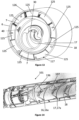
- each baffle 16, 17, 18 in the central chamber includes a hood, scoop or cowling 30 extending rearward from the orthogonal surface or rim 16b about the projectile aperture 13 and/or the side wall 16a of the baffle.
- the cowling 30 is adjacent the projectile aperture 13 through the baffle.
- the cowling 30 is proximate the long side 16a(i) of the baffle side wall 16a, i.e. the long side of the cone frustum forming the side wall.
- the cowling extends for a portion of the circumference of the projectile aperture 13 and in the illustrated embodiment approximately half way around the circumference of the projectile aperture 13.
- the cowling 30 acts to direct a portion of the flow of gases at the projectile aperture in a direction orthogonal to the longitudinal axis of the suppressor.
- the cowling creates an area of high pressure that extends at least part way across the projectile aperture 13.
- the area of high pressure creates or causes a 'virtual' wall at least part way across the projectile aperture, which further assists with moving the gases off the central passageway through the suppressor and outwards to the outer chamber.
- An inner surface of the cowling facing towards the projectile aperture is preferably concave and may curve through approximately 90 degrees from parallel to a longitudinal axis of the suppressor at a rear end of the cowling to perpendicular to the longitudinal axis at a forward end of the cowling.
- FIGS 14 to 16 show a suppressor 101 according to another embodiment of the present invention.
- one or more inner baffles 16, 17 of suppressor 101 comprises a secondary baffle wall 136, 137 extending radially outwards and in a rearward direction of the suppressor from adjacent the projectile aperture to the tubular inner wall 7.
- the secondary baffle wall may extend from the baffle wall 16a described above, and/or the orthogonal surface adjacent the projectile aperture 13.
- the secondary baffle wall 136, 137 extends from a rear end of the cowling 30 to the inside of the inner tubular wall 7.
- the secondary baffle may extend from adjacent the projectile aperture to an upstream inner baffle, e.g. secondary baffle wall 137 may extend to baffle wall 16a.
- the secondary wall 136, 137 extends for a portion of the circumference of the projectile aperture 13 and in the illustrated embodiment approximately half way around the circumference of the projectile aperture 13.
- the secondary baffle wall acts as a funnel to direct a portion of the flow of gases at the projectile aperture 13 in a direction orthogonal to the longitudinal axis of the suppressor. This may assist with creating an area of high pressure that extends at least part way across the projectile aperture 13, to cause a virtual baffle at least part way across the projectile aperture 12, as described above for the cowling. Where the secondary wall extends from the rear edge of the cowling, the secondary wall acts to funnel a portion of the flow of gases to the cowling which then directs the flow to the projectile aperture 13 in a direction orthogonal to the longitudinal axis of the suppressor.
- gases flow in the inner chamber 10 can flow beyond the secondary wall 136, 137 to act against the wall 16a, 17a of the baffle 16, 17 off the axis of the projectile passageway through the suppressor 101.
- the suppressor may comprise equalisation holes 40 in the inner wall 7 dividing the central 10 and outer 110 chambers.
- the equalisation holes 40 allow for gases to flow from the inner chamber 10 to the outer chamber 110 as the gases flow/expand forward through the suppressor.
- the suppressor may comprise at least one chamber equalisation hole 40 through the inner wall 7 within each sub chamber 19-22 of the central flow path.
- Each equalisation hole 40 is preferably formed towards a forward end of the sub-chamber.
- the suppressor may comprise a plurality of equalisation holes towards a forward end of one or more sub-chamber, adjacent where the forward baffle of the sub-chamber meets the inner wall, i.e. forward baffle 16 of the first sub-chamber 19.
- the first two sub-chambers 19 and 20 comprise equalisation holes spaced approximately 90degrees apart around the inner wall 7, at a 12 o'clock, 3 o'clock, 6 o'clock and 9 o'clock positions, wherein a longest side (16a(i) in Figure 12 ) of the asymmetric or truncated cone shaped wall 16a of the forward baffle meets the inner wall 7 at the 12 o'clock position.
- the hole at the 6 o'clock position is in angular alignment with the short side (16a(ii) in Figure 12 ) of the asymmetric wall 16a of the baffle, and the hole at the 12 o'clock position is in angular alignment with the long side 16a(i) of the asymmetric wall of the baffle.
- the first sub chamber 19 comprises a plurality of holes 40 (refer to Figure 6 ) arranged together in a group of holes, and in the illustrated embodiment four holes, at or in proximity to the 6 o'clock position.
- the third sub-chamber 21 comprises a single equalisation hole at the 6 o-clock position.
- the fourth sub-chamber comprises a single equalisation hole at the 6 o-clock position in relation to the baffle at the rearward end of the fourth sub-chamber.
- the hole is positioned approximately midway along the inner wall 7 between the end wall 5 and the baffle.
- the inventor postulates that as the gases enter each sub-chamber 19, 20, 21 they flow/expand over the forward baffle of the chamber into a narrow space between the baffle 16, 17, 18 and the inner wall 7 beyond the projectile aperture 13 of the baffle, and then flow from the central chamber to the outer chamber via the equalisation holes 40.
- each baffle placed at an angle to a plane perpendicular to the longitudinal axis of the suppressor causes the flow to enter each sub-chamber 20, 21, 22 at least partially in a radially outwards direction, for example a direction along/parallel to the short side of the truncated cone shaped section of the baffle, which causes the gases to be directed towards the equalisation hole located at the 6 o'clock position; refer to arrows through the baffle projectile apertures in Figure 4 .
- the pressure in the blast chamber is high. This high pressure results in flow from the blast chamber to the outer chamber via the inlet baffle 115. However, after the initial high pressure in the blast chamber reduces, the blast chamber pressure no longer provides a mechanism to continue to feed gases to the outer chamber or to drive gases forward through the outer chamber. The flow in the outer chamber can therefore stagnate unless measures are taken to keep the flow of gases moving forward through the outer chamber 110.
- the pressure in the outer chamber 110 reduces in the forward direction.
- the outer chamber increases in volume in a forward direction through the suppressor, i.e. the outer chamber increases in volume towards the exit end 3 of the suppressor 1.
- the pressure within the chamber is reduced. This assists in moving gases forwards through the suppressor via the outer chamber 110 while also working the gases effectively within the central chamber 10.
- the inventor postulates that to achieve both effective sound suppression while at the same time removing as much gases and therefore pressure as possible from the suppressor and firearm system prior to bolt opening, it is important to remove as much of the gases flow off the projectile passageway of the suppressor as possible to the outer chamber 110 while balancing the pressure between the inner and outer chambers so that the gases exit the inner and outer chambers at the same time.
- the suppressor must be arranged so that the outer flow does not exit the suppressor significantly before the inner flow and vice versa. For example, in one embodiment the outer flow exits the suppressor within 100 micro seconds of the inner flow exiting the suppressor. In some embodiments, the outer flow exits the suppressor within 80 micro seconds, or within 60 micro seconds, or within 50 micro seconds of the inner flow exiting the suppressor.
- the inner and outer flows should exhaust in substantially the same time period.
- the inner and outer flows should begin exiting the suppressor at substantially the same time and complete exiting the suppressor at substantially the same time.
- the outer flow should begin exiting the suppressor within 100micro seconds or less of the inner flow beginning to exit the suppressor, and the outer flow should have completely exhausted from the suppressor within 100microseconds of the inner flow having completely exhausted from the suppressor. These timings may be within 80 micros seconds, or within 60 micro seconds, or within 50 micro seconds.
- the inner wall 7 may be part conical in shape so that the diameter of the inner chamber 10 reduces from the inlet end towards the exit end of the suppressor, with a corresponding increase in radial width of the outer chamber 110 from the inlet end to the exit end of the suppressor.
- a reducing volume in the forward direction for the inner chamber 10 may also assist with moving gases off the central passageway of the suppressor to the outer chamber 110 via equalisation holes 40 through the inner wall 7.
- the reducing volume of the central chamber may work to cause an increasing pressure in the inner chamber the forward direction which causes flow to the outer chamber to balance pressure between the inner and outer chambers.
- the volume of the central chamber may be approximately constant along the length of the suppressor (not accounting for volume taken up by baffle material within the chamber).
- the inner wall 7 may be cylindrical, and the outer wall 6 may be conical with an increasing diameter towards the exit end 5 of the suppressor as shown in the Figures.
- the outer chamber 110 comprises one or more outer baffles 116 to 119 ( Figure 11 ) dividing the outer chamber 110 into a series of sub-chambers 120 to 124.
- there are four baffle arrangements in the outer chamber however in alternative embodiments, there may be one, two, three or more than four baffles.
- the inventor believes that it is important to direct gases received in the blast chamber to the outer chamber.
- the inlet 113 to the outer chamber has an area equal to or greater than the area of the projectile aperture 13 of the first baffle.
- the inventor believes that it is preferable to balance pressure (i.e. reduce pressure differential) between the inner and outer chambers.
- pressure i.e. reduce pressure differential
- the inventor believes it is necessary to include baffles within the outer chamber to slow down the flow of gases in the outer chamber in the forward direction by increasing the resistance to flow through the outer chamber in the forward direction.
- the pressure differential across the inlet baffle 115 between the blast chamber 14 and the outer chamber drops 110.
- the inlet baffle since the inlet baffle has a higher resistance to flow than the first baffle, the inlet baffle acts to prevent a reverse flow from the outer chamber and back into the blast chamber (and subsequent flow in to the inner chamber).
- the second baffle 117 may provide a lower resistance to flow than the first baffle 116. Additionally or alternatively, and as shown in the illustrated embodiment, the second baffle comprises a plurality of blades 125 (refer Figure 13 ) arranged circumferentially to impart a swirl or whirl direction to the gases to cause the gases to move forward through the outer chamber 110 with a swirling or whirling motion circumferentially around the outer chamber in a first circumferential direction, i.e. an anti-clockwise direction in an end view on the rear or inlet end of the suppressor.
- the swirling flow is considered to be parallel to the inner flow path since the swirling flow maintains a forward flow component and without a rearward flow component.
- the third baffle 118 also comprises a plurality of blades arranged circumferentially to impart a swirl or whirl direction to the gases, however are arranged to cause a swirling or whirling motion circumferentially around the outer chamber 110 in a second circumferential direction opposite to the first direction, i.e. in a clockwise direction in an end view on the rear or inlet end of the suppressor.
- the second and third baffles 117, 118 in the outer chamber 110 therefore create a circumferential tortuous path which aids in a further slowing of the gases in a forward direction through the outer chamber.
- the effect of the swirling motion is to increase the flow path of the gases through the outer chamber.
- the fourth and last outer baffle 119 comprises a plurality of blades arranged circumferentially to impart a swirl or whirl direction to the gases to cause the gases to move forward through the outer chamber with a swirling or whirling motion circumferentially around the outer chamber in the first circumferential direction, to further extend the circumferential tortuous path of the gases through the outer circumferential direction.
- the second and third baffles 117, 118 comprise a wall 126 (refer Figure 13 ) extending in the longitudinal direction of the suppressor between tips of blades 125, with holes through the walls.
- suppressor may be without such walls between the blades.
- the fourth baffle 119 is without a wall between adjacent blades.
- the walls 126 with holes may be provided to further restrict flow while providing blades 125 with sufficient helical travel in the longitudinal direction to impact a whirling motion with a forward component.
- the inner flow through the last portion of the inner chamber 10 i.e. the flow through the last sub chamber 22 does not make effective use of the volume of the last sub chamber 22 because the gases are close to the exit aperture 9 and therefore tend to pass straight out the exit end of the suppressor. Consequently, the suppressor benefits from an increased volume in the outer chamber 110 flow path to draw more flow from the inner chamber 10 to the outer chamber 110.
- the forward flow velocity in the outer chamber may be slowed by creating circumferential flow in the outer chamber.
- the suppressor should be configured to direct gases flow into the outer chamber and as much gases off the projectile passageway as possible, and to balance pressure between the inner chamber and outer chamber along the length of the suppressor, or in other words match/balance the velocity/rate of gases flow along the inner and outer chambers, so that the gases exit from the inner and outer chambers at the same time.
- the inner and outer chambers are sized and configured including balancing of pressures between the inner and outer chambers so that the inner and outer chambers work the gases so that the gases exit the inner and outer chambers approximately at the same time.
- the gases may initially exit the inner chamber before the outer chamber, however flow through the outer chamber may ⁇ catch up' with gases subsequently exiting the outer chamber more quickly than the inner chamber, with finally all gases exhausted from the inner and outer chambers in substantially the same time period.
- the end result in the balancing of the flow through the inner and outer chambers is that the gases exhaust from the inner and outer chambers via the exit outlet 9 and the outlet apertures 8 at approximately at the same time.
- the volume or flow rate of gases through the outer chamber is balanced or equal to the volume or flow rate of gases through the inner chamber. However, more or less volume and therefore flow may pass through the outer chamber than the inner chamber, but all gases flow/volume should be exhausted from the inner and outer chambers in approximately the same time and in the same time period.
- a projectile cartridge produces a volume of gas on firing. This volume of gas flows through the suppressor.
- the volume of gas is split or divided at the blast chamber into two parts, a first volume to flow into the outer chamber and a second volume to flow into the inner chamber.
- the first volume of gases entering the outer chamber may be equal to the second volume of gases entering the inner chamber or may be more than or less than the second volume of gases entering the inner chamber.
- the first volume of gases that flows into the outer chamber should exit the suppressor in substantially the same time period as the second volume of gases that flows into the inner chamber.
- the suppressor comprises equalisation holes to balance pressure between the inner and outer chambers. These holes can for example allow flow from the inner chamber to the outer chamber along the length of the suppressor.
- flow that entered the inner chamber from the blast chamber may flow through one or more equalisation holes 40 to flow through a portion of the outer chamber 110 and exit the suppressor via the outlet apertures 8.
- substantially all of the volume/flow of gases entering the outer chamber 110 from the blast chamber flows through the outer chamber and exits the outer chamber via the outlet apertures 8.
- a portion of the volume/flow of gases entering the inner chamber 10 exits the suppressor via the exit outlet 9 and a portion exits the suppressor via the outlet apertures 8.
- Balancing pressure/flowrate/velocity between the inner and outer chambers along the length of the suppressor to ensure the inner and outer flows exit the suppressor at the same time may require a slowing down of the forward flow of gases in the outer chamber, such that the gases can still be aggressively worked by the baffles in the inner chamber while allowing for pressure/flowrate/velocity matching between the two parallel flow paths.
- ⁇ Matching rates/velocities means the flow rate/velocity in each flow path result in the inner and outer flows exiting the suppressor at the same time.
- the outer flow may be higher or lower than the inner flow while being 'matched' with the inner flow to exit the suppressor at the same time as the inner flow.
- the inventor recommends building a suppressor with an inner chamber and outer chamber as described, with one or more inner baffles in the inner chamber to work the gases to achieve effective noise reduction, and with one or more outer baffles in the outer chamber. If the suppressor results in a gases flow in the outer chamber that is higher flow and/or lower pressure than the gases flow in the inner chamber, modifications should be made to the forward most baffles in the outer chamber, e.g. baffles three, four and five, 117, 118 and 119, in the illustrated embodiment, to slow the rate of gases flowing though the outer chamber, to achieve pressure/flow balancing between the inner and outer chambers.
- Modifications can include introducing whirl baffles and a circumferential tortuous path.
- the number and size of equalisation holes 40 in the tubular inner wall may also be adjusted until the desired balancing affect is achieved.
- the inventor has disclosed herein arrangements to achieve a balancing between the inner and outer chambers 10 and 110, including:
- equalization vents 40 allow for flexibility to accommodate a wider range of ammunition than a suppressor without equalization holes with a single calculated flow path optimized for a single ammunition type.
- the effect of moving flow from the inner chamber to the outer chamber has the effect of keeping the overall suppressor volume small while achieving effect sound suppression. Since the gases are processed through the inner and outer chambers equally for flow restriction, volume and pressure, improved sound suppression can be achieved in a shorter time frame. Testing has indicated a suppression time of around half of the suppression time of prior art suppressors. This results in reduced back pressure and allows the suppressor pressure to drop before the firearm bolt automatically opens. A sound suppressor according to the present invention is therefore particularly useful for semi and fully automatic firearms. Such a suppressor may not benefit firearms with a manual bolt system.
Landscapes
- Engineering & Computer Science (AREA)
- General Engineering & Computer Science (AREA)
- Aiming, Guidance, Guns With A Light Source, Armor, Camouflage, And Targets (AREA)
Claims (10)
- Ein Schalldämpfer (4) für eine Schusswaffe, der Folgendes beinhaltet:ein Anschlüssstück (4) zum Anbringen des Schalldämpfers (1) an einem Lauf einer Schusswaffe an oder in Richtung eines Einlassendes (2) des Schalldämpfers (1), wobei das Anschlussstück (4) einen Einlass in den Schalldämpfer (1) bereitstellt,eine Endwand (5) an einem Austrittsende des Schalldämpfers (1), wobei die Endwand (5) einen Austrittsauslass (9) und mindestens eine Gasauslassöffnung (8) beinhaltet, wobei der Austrittsauslass (9) auf den Einlass (2) ausgerichtet ist, um eine Projektilbahn zum Durchqueren des Schalldämpfers (1) durch ein Projektil zu bilden, eine röhrenförmige Seitenwand (6), die sich zwischen dem Austrittsende (9) und dem Einlassende (2) erstreckt und eine Außenhülle definiert,eine röhrenförmige Innenwand (7), die die innere Kammer (10) und die äußere Kammer (110) innerhalb der Hülle definiert,eine Druckkammer (14) innerhalb der Außenhülle, die an das Einlassende (2) angrenzt, wobei die Druckkammer (14) eine erste Prallwand (15) beinhaltet, die eine Einlassendwand zur inneren Kammer (10) bereitstellt, wobei die erste Prallwand (15) eine Projektilöffnung (13) beinhaltet, die auf den Austrittsauslass (9) ausgerichtet ist,wobei die erste Prallwand (15) konfiguriert ist, um Strömung zur äußeren Kammer (110) zu lenken,wobei die innere Kammer (10) einen Gasinnenströmungspfad bereitstellt, damit eine Innenströmung von Gasen in eine Vorwärtsrichtung von der Druckkammer (14) zu dem Austrittsauslass (9) strömt,wobei der Schalldämpfer (1) eine oder mehrere innere Prallwände (16, 17, 18) beinhaltet, die entlang der Länge der inneren Kammer (10) beabstandet sind, wobei sich jede innere Prallwand (10) von der Innenwand (7) erstreckt und eine Projektilöffnung (13) beinhaltet, die auf den Einlass (2) und den Austrittsauslass (9) auf der Projektilbahn ausgerichtet ist, wobei die eine oder die mehreren inneren Prallwände (16, 17, 18) die innere Kammer (10) in eine Reihe von inneren Unterkammern (19, 20, 21, 22) teilen,wobei die äußere Kammer (110) einen Gasaußenströmungspfad bereitstellt, damit eine Außenströmung von Gasen in die Vorwärtsrichtung von der Druckkammer (14) zu der mindestens einen Gasauslassöffnung strömt, wobei der Außenströmungspfad zu dem Innenströmungspfad parallel ist,wobei die äußere Kammer (110) in Richtung des Austrittsendes (9) an Volumen zunimmt und/oder die innere Kammer (10) in Richtung des Austrittsendes (9) an Volumen abnimmt,wobei der Schalldämpfer (1) eine oder mehrere äußere Prallwände (116, 117, 118, 119) beinhaltet, die entlang der Länge der äußeren Kammer (110) beabstandet sind und die äußere Kammer (110) in eine Reihe von äußeren Unterkammern (120, 121, 122, 123, 124) teilen,wobei die äußere Kammer (110) ferner eine Einlassprallwand (115) der äußeren Kammer beinhaltet, wobei die Einlassprallwand (115) der äußeren Kammer mindestens eine Öffnung (113) beinhaltet, um einen Einlass in die äußere Kammer (110) bereitzustellen,wobei die Gesamtfläche der mindestens einen Öffnung (113) in der Einlassprallwand (115) der äußeren Kammer gleich oder größer ist als die Fläche der Projektilöffnung (13), wobei ein Strömungswiderstand einer zweiten äußeren Prallwand (116, 117, 118, 119) innerhalb der äußeren Kammer (110) geringer als ein Strömungswiderstand der Einlassprallwand (116, 117, 118, 119) der äußeren Kammer ist, wobei sich die zweite Prallwand näher an dem Austrittsende (9) des Schalldämpfers (1) als die Einlassprallwand (115) der äußeren Kammer befindet,wobei die äußere Kammer (110) über keinen Gegenstromgasströmungspfad in einer entgegengesetzten rückwärtsgewandten Richtung zwischen der Druckkammer (14) und dem mindestens einen Gasauslass (9) verfügt,wobei die Gesamtfläche der mindestens einen Gasauslassöffnung (8) ungefähr gleich oder größer ist als die Fläche der Projektilöffnung (13), undwobei der Schalldämpfer (1) so konfiguriert ist, dass Gasdruck zwischen der inneren Kammer (10) und der äußeren Kammer (110) entlang der Länge der inneren (10) und äußeren (110) Kammer ausgewogen ist, sodass Gase aus der inneren (10) und äußeren (110) Kammer über den Austrittsauslass (9) und die mindestens eine Auslassöffnung (8) im Wesentlichen zur selben Zeit entweichen.
- Schalldämpfer (1) gemäß Anspruch 1, der Ausgleichslöcher (40) in der röhrenförmigen Innenwand (7) beinhaltet, um Gasströmung von dem inneren Strömungspfad in den parallelen äußeren Strömungspfad zu gestatten, wenn Gase, die durch Abfeuern der Schusswaffe erzeugt wurden, von der Druckkammer (14) zu dem Austrittsauslass (9) über den inneren Strömungspfad und zu der mindestens einen Gasauslassöffnung (8) über den parallelen äußeren Strömungspfad durch den Schalldämpfer (1) strömen und/oder sich dadurch ausdehnen.
- Schalldämpfer (1) gemäß einem der Ansprüche 1 oder 2, wobei der Schalldämpfer (1) mindestens ein Ausgleichsloch (40) durch die röhrenförmige Innenwand (7) innerhalb jeder Unterkammer (19, 20, 21, 22) der inneren Kammer (10) beinhaltet, und
wobei eine oder mehrere Unterkammern (19, 20, 21, 22) der inneren Kammer (10) mindestens ein Ausgleichsloch (40) angrenzend an ein vorderes Ende der Unterkammer (19, 20, 21, 22) beinhalten und/oder wobei eine oder mehrere Unterkammern (19, 20, 21, 22) der inneren Kammer (10) eine Vielzahl von Ausgleichslöchern (40) beinhalten, die um die röhrenförmige Innenwand (7) in Umfangsrichtung beabstandet sind. - Schalldämpfer (1) gemäß einem der Ansprüche 1, 2 oder 3, wobei eine oder mehrere der inneren Prallwände (16, 17, 18) eine asymmetrische Prallwandseitenwand beinhalten, die eine lange Seite und eine diametral entgegengesetzte kurze Seite beinhaltet, und wobei eine oder mehrere Unterkammern (19, 20, 21, 22) der inneren Kammer (10) ein Ausgleichsloch (40) in Winkelfluchtung mit der kurzen Seite der Prallwandseitenwand (16a) beinhalten.
- Schalldämpfer (1) gemäß einem der Ansprüche 1 bis 4, wobei eine oder mehrere der inneren Prallwände (16, 17, 18) die Projektilöffnung (13) in einem Winkel zu einer Ebene angeordnet aufweisen, die senkrecht zu dem Projektildurchgang ist.
- Schalldämpfer (1) gemäß einem der Ansprüche 1 bis 5, wobei eine oder mehrere der inneren Prallwände (16, 17, 18) eine Haube (30) beinhalten, die sich von der Prallwandseitenwand (16a) und/oder einer Oberfläche oder einem Rand um die Projektilöffnung (13) rückwärtsgewandt erstreckt, wobei die Haube (30) geformt ist, um einen Teil einer Strömung von Gasen an der Projektilöffnung (13) in eine Richtung zu lenken, die orthogonal zu dem Projektildurchgang verläuft, und/oder einen Bereich erhöhten Drucks zu erzeugen, der sich mindestens teilweise über die Projektilöffnung erstreckt.
- Schalldämpfer (1) gemäß einem der Ansprüche 1 bis 6, wobei die röhrenförmige Seitenwand (6) zylindrisch ist und die röhrenförmige Innenwand (7) zum Teil konisch ist, sodass der Durchmesser der inneren Kammer (10) in einer Vorwärtsrichtung durch den Schalldämpfer (1) abnimmt, bei einer entsprechenden Erhöhung der radialen Breite der äußeren Kammer (110) in der Vorwärtsrichtung durch den Schalldämpfer (1).
- Schalldämpfer (1) gemäß einem der Ansprüche 1 bis 7,
wobei eine oder mehrere der hinteren äußeren Prallwände (116, 117, 118, 119) einen höheren Strömungswiderstand als eine oder mehrere vordere äußere Prallwände (116, 117, 118, 119) aufweisen. - Schalldämpfer (1) gemäß einem der Ansprüche 1 bis 8, wobei mindestens eine oder mehrere äußere Prallwände (116, 117, 118, 119) eine Wirbelbewegung in Umfangsrichtung um die äußere Kammer (110) verleihen, und/oder wobei mindestens zwei äußere Prallwände (116, 117, 118, 119) jeweils eine Wirbelbewegung in Umfangsrichtung um die äußere Kammer (110) verleihen, wobei eine erste Wirbelprallwand eine Wirbelbewegung in einer ersten Umfangsrichtung verleiht und eine zweite Wirbelprallwand eine Wirbelbewegung in Umfangsrichtung um die äußere Kammer (110) in einer zweiten Umfangsrichtung verleiht.
- Schalldämpfer (1) gemäß einem der vorhergehenden Ansprüche, wobei ein Strömungsbereich eines Einlasses in die äußere Kammer (110) größer als oder gleich einem Strömungsbereich eines Einlasses in die innere Kammer (10) ist.
Applications Claiming Priority (2)
| Application Number | Priority Date | Filing Date | Title |
|---|---|---|---|
| NZ74868918 | 2018-11-26 | ||
| PCT/NZ2019/050153 WO2020111950A1 (en) | 2018-11-26 | 2019-11-26 | A suppressor for a gun |
Publications (4)
| Publication Number | Publication Date |
|---|---|
| EP3887745A1 EP3887745A1 (de) | 2021-10-06 |
| EP3887745A4 EP3887745A4 (de) | 2022-08-31 |
| EP3887745B1 true EP3887745B1 (de) | 2024-07-24 |
| EP3887745C0 EP3887745C0 (de) | 2024-07-24 |
Family
ID=70851834
Family Applications (1)
| Application Number | Title | Priority Date | Filing Date |
|---|---|---|---|
| EP19891577.9A Active EP3887745B1 (de) | 2018-11-26 | 2019-11-26 | Schalldämpfer für eine waffe |
Country Status (4)
| Country | Link |
|---|---|
| US (2) | US11268778B2 (de) |
| EP (1) | EP3887745B1 (de) |
| AU (1) | AU2019390209B2 (de) |
| WO (1) | WO2020111950A1 (de) |
Families Citing this family (7)
| Publication number | Priority date | Publication date | Assignee | Title |
|---|---|---|---|---|
| FI129865B (fi) * | 2020-10-15 | 2022-10-14 | Silent Steel Oy | Aseen vaimennin |
| US20220276016A1 (en) * | 2021-02-26 | 2022-09-01 | Surefire, Llc | Firearm sound suppressor with peripheral venting |
| DK181359B1 (en) * | 2021-12-15 | 2023-08-31 | Due Jensen Niels | A noise suppressor for a firearm |
| US12264889B2 (en) * | 2023-01-13 | 2025-04-01 | Replicator LLC | Suppressor for a firearm |
| WO2024173046A2 (en) * | 2023-02-01 | 2024-08-22 | Sig Sauer, Inc. | Suppressor baffle |
| US11703303B1 (en) * | 2023-03-10 | 2023-07-18 | Polaris Capital Corporation | Air gun moderator and multi-layer moderator core |
| USD1080792S1 (en) | 2023-06-07 | 2025-06-24 | Mountain Tactical Company | Firearm suppressor |
Family Cites Families (16)
| Publication number | Priority date | Publication date | Assignee | Title |
|---|---|---|---|---|
| US1017003A (en) * | 1910-05-16 | 1912-02-13 | Charles H Kenney | Silencer for firearms. |
| NZ610168A (en) | 2010-10-05 | 2013-10-25 | John William Bladen | Sound suppressor for firearm |
| ES2628909T3 (es) * | 2012-11-15 | 2017-08-04 | Sako Oy | Silenciador de arma de fuego |
| US9102010B2 (en) * | 2012-12-21 | 2015-08-11 | Bert John WILSON | Suppressors and their methods of manufacture |
| US9347727B1 (en) * | 2014-04-29 | 2016-05-24 | The United States Of America As Represented By The Secretary Of The Army | Automatic weapon suppressor |
| DE102015002710A1 (de) | 2015-03-04 | 2016-09-08 | Victor Miles As | Schalldämpfer mit Expansionsräumen und Verfahren zu dessen Herstellung |
| US9739559B2 (en) | 2015-10-07 | 2017-08-22 | Century International Arms, Inc. | Sound suppressor |
| US20170160034A1 (en) * | 2015-12-02 | 2017-06-08 | CGS Group. LLC | Suppressor with Coaxial Expansion Chambers and Tapered Seals |
| US20180038663A1 (en) * | 2016-08-08 | 2018-02-08 | Mark C. LaRue | Suppressed upper receiver group having locking suppressor with through brake |
| US20180135932A1 (en) * | 2016-10-26 | 2018-05-17 | Nicholas Tomczak | Suppressor for a firearm |
| WO2018161087A1 (en) * | 2017-03-03 | 2018-09-07 | Cgs Group, Llc | Suppressor with varying core diameter |
| US10180299B2 (en) * | 2017-03-15 | 2019-01-15 | M Combat, Inc. | Flash suppressor assembly and method |
| US10739097B1 (en) * | 2017-08-11 | 2020-08-11 | Lance L. Gaines | Thermal respirating sound suppressor |
| US10753699B2 (en) * | 2018-10-08 | 2020-08-25 | Ut-Battelle, Llc | Flow through suppressor with enhanced flow dynamics |
| US11255623B2 (en) * | 2019-04-30 | 2022-02-22 | Sig Sauer, Inc. | Suppressor with reduced gas back flow and integral flash hider |
| US11162753B2 (en) * | 2019-05-03 | 2021-11-02 | Sig Sauer, Inc. | Suppressor with integral flash hider and reduced gas back flow |
-
2019
- 2019-11-26 EP EP19891577.9A patent/EP3887745B1/de active Active
- 2019-11-26 AU AU2019390209A patent/AU2019390209B2/en active Active
- 2019-11-26 US US16/768,561 patent/US11268778B2/en active Active
- 2019-11-26 WO PCT/NZ2019/050153 patent/WO2020111950A1/en not_active Ceased
-
2022
- 2022-03-07 US US17/688,392 patent/US11674771B2/en active Active
Also Published As
| Publication number | Publication date |
|---|---|
| AU2019390209A1 (en) | 2021-07-15 |
| WO2020111950A1 (en) | 2020-06-04 |
| US11268778B2 (en) | 2022-03-08 |
| US20220276017A1 (en) | 2022-09-01 |
| US20210239418A1 (en) | 2021-08-05 |
| US11674771B2 (en) | 2023-06-13 |
| EP3887745A1 (de) | 2021-10-06 |
| EP3887745A4 (de) | 2022-08-31 |
| EP3887745C0 (de) | 2024-07-24 |
| AU2019390209B2 (en) | 2025-11-20 |
Similar Documents
| Publication | Publication Date | Title |
|---|---|---|
| EP3887745B1 (de) | Schalldämpfer für eine waffe | |
| US9909829B2 (en) | Muzzle brake | |
| US7237467B1 (en) | Sound suppressor | |
| US9207033B2 (en) | Firearm suppressor baffle | |
| US4879942A (en) | Muzzle brake with improved stabilization and blast control | |
| EP3245472B1 (de) | Feuerwaffenaufsatz | |
| US20220276016A1 (en) | Firearm sound suppressor with peripheral venting | |
| US9291417B2 (en) | Noise suppressor for firearms | |
| US20160076844A1 (en) | Brake Mounted Firearm Noise Suppressor | |
| US11859932B1 (en) | Machine gun suppressor | |
| US11221189B1 (en) | Method and apparatus for parallel path firearm sound suppression | |
| US9163892B1 (en) | Muzzle break with supersonic nozzle | |
| US3141376A (en) | Flame-out eliminator | |
| US20250314445A1 (en) | Diverging central bore for firearm sound suppressor | |
| EP0151112A1 (de) | Waffenstabilisator und -rückstossverminderer | |
| US6575266B1 (en) | Tube barrel weapon | |
| US20230039423A1 (en) | Firearm sound suppressor with peripheral venting | |
| JPH08503295A (ja) | 縮射用弾薬要素の制御分離を備えた送弾筒 | |
| RU2225974C1 (ru) | Способ придания вращения пулевому или иному снаряду и огнестрельный комплекс яугонена для его осуществления | |
| KR20230140453A (ko) | 폭발 감쇠 장치 | |
| US12492877B2 (en) | Suppression device for rotary machine gun | |
| US20250277642A1 (en) | Suppression device for rotary machine gun | |
| SK346892A3 (en) | Sound dumper of fire arm | |
| CN110986664A (zh) | 一种多功能高效率的制退器 | |
| JPH10267593A (ja) | 砲口制退器 |
Legal Events
| Date | Code | Title | Description |
|---|---|---|---|
| STAA | Information on the status of an ep patent application or granted ep patent |
Free format text: STATUS: THE INTERNATIONAL PUBLICATION HAS BEEN MADE |
|
| PUAI | Public reference made under article 153(3) epc to a published international application that has entered the european phase |
Free format text: ORIGINAL CODE: 0009012 |
|
| STAA | Information on the status of an ep patent application or granted ep patent |
Free format text: STATUS: REQUEST FOR EXAMINATION WAS MADE |
|
| 17P | Request for examination filed |
Effective date: 20210621 |
|
| AK | Designated contracting states |
Kind code of ref document: A1 Designated state(s): AL AT BE BG CH CY CZ DE DK EE ES FI FR GB GR HR HU IE IS IT LI LT LU LV MC MK MT NL NO PL PT RO RS SE SI SK SM TR |
|
| DAV | Request for validation of the european patent (deleted) | ||
| DAX | Request for extension of the european patent (deleted) | ||
| A4 | Supplementary search report drawn up and despatched |
Effective date: 20220728 |
|
| RIC1 | Information provided on ipc code assigned before grant |
Ipc: F41A 21/32 20060101ALI20220722BHEP Ipc: F41A 21/30 20060101AFI20220722BHEP |
|
| GRAP | Despatch of communication of intention to grant a patent |
Free format text: ORIGINAL CODE: EPIDOSNIGR1 |
|
| STAA | Information on the status of an ep patent application or granted ep patent |
Free format text: STATUS: GRANT OF PATENT IS INTENDED |
|
| INTG | Intention to grant announced |
Effective date: 20231019 |
|
| GRAJ | Information related to disapproval of communication of intention to grant by the applicant or resumption of examination proceedings by the epo deleted |
Free format text: ORIGINAL CODE: EPIDOSDIGR1 |
|
| STAA | Information on the status of an ep patent application or granted ep patent |
Free format text: STATUS: REQUEST FOR EXAMINATION WAS MADE |
|
| GRAP | Despatch of communication of intention to grant a patent |
Free format text: ORIGINAL CODE: EPIDOSNIGR1 |
|
| STAA | Information on the status of an ep patent application or granted ep patent |
Free format text: STATUS: GRANT OF PATENT IS INTENDED |
|
| INTC | Intention to grant announced (deleted) | ||
| INTG | Intention to grant announced |
Effective date: 20240301 |
|
| GRAS | Grant fee paid |
Free format text: ORIGINAL CODE: EPIDOSNIGR3 |
|
| GRAA | (expected) grant |
Free format text: ORIGINAL CODE: 0009210 |
|
| STAA | Information on the status of an ep patent application or granted ep patent |
Free format text: STATUS: THE PATENT HAS BEEN GRANTED |
|
| AK | Designated contracting states |
Kind code of ref document: B1 Designated state(s): AL AT BE BG CH CY CZ DE DK EE ES FI FR GB GR HR HU IE IS IT LI LT LU LV MC MK MT NL NO PL PT RO RS SE SI SK SM TR |
|
| REG | Reference to a national code |
Ref country code: GB Ref legal event code: FG4D |
|
| REG | Reference to a national code |
Ref country code: CH Ref legal event code: EP |
|
| REG | Reference to a national code |
Ref country code: DE Ref legal event code: R096 Ref document number: 602019055914 Country of ref document: DE |
|
| REG | Reference to a national code |
Ref country code: IE Ref legal event code: FG4D |
|
| U01 | Request for unitary effect filed |
Effective date: 20240724 |
|
| U07 | Unitary effect registered |
Designated state(s): AT BE BG DE DK EE FI FR IT LT LU LV MT NL PT SE SI Effective date: 20240730 |
|
| U20 | Renewal fee for the european patent with unitary effect paid |
Year of fee payment: 6 Effective date: 20241127 |
|
| PG25 | Lapsed in a contracting state [announced via postgrant information from national office to epo] |
Ref country code: NO Free format text: LAPSE BECAUSE OF FAILURE TO SUBMIT A TRANSLATION OF THE DESCRIPTION OR TO PAY THE FEE WITHIN THE PRESCRIBED TIME-LIMIT Effective date: 20241024 |
|
| PG25 | Lapsed in a contracting state [announced via postgrant information from national office to epo] |
Ref country code: GR Free format text: LAPSE BECAUSE OF FAILURE TO SUBMIT A TRANSLATION OF THE DESCRIPTION OR TO PAY THE FEE WITHIN THE PRESCRIBED TIME-LIMIT Effective date: 20241025 Ref country code: PL Free format text: LAPSE BECAUSE OF FAILURE TO SUBMIT A TRANSLATION OF THE DESCRIPTION OR TO PAY THE FEE WITHIN THE PRESCRIBED TIME-LIMIT Effective date: 20240724 |
|
| PG25 | Lapsed in a contracting state [announced via postgrant information from national office to epo] |
Ref country code: IS Free format text: LAPSE BECAUSE OF FAILURE TO SUBMIT A TRANSLATION OF THE DESCRIPTION OR TO PAY THE FEE WITHIN THE PRESCRIBED TIME-LIMIT Effective date: 20241124 |
|
| PG25 | Lapsed in a contracting state [announced via postgrant information from national office to epo] |
Ref country code: HR Free format text: LAPSE BECAUSE OF FAILURE TO SUBMIT A TRANSLATION OF THE DESCRIPTION OR TO PAY THE FEE WITHIN THE PRESCRIBED TIME-LIMIT Effective date: 20240724 |
|
| PG25 | Lapsed in a contracting state [announced via postgrant information from national office to epo] |
Ref country code: RS Free format text: LAPSE BECAUSE OF FAILURE TO SUBMIT A TRANSLATION OF THE DESCRIPTION OR TO PAY THE FEE WITHIN THE PRESCRIBED TIME-LIMIT Effective date: 20241024 Ref country code: ES Free format text: LAPSE BECAUSE OF FAILURE TO SUBMIT A TRANSLATION OF THE DESCRIPTION OR TO PAY THE FEE WITHIN THE PRESCRIBED TIME-LIMIT Effective date: 20240724 |
|
| PG25 | Lapsed in a contracting state [announced via postgrant information from national office to epo] |
Ref country code: RS Free format text: LAPSE BECAUSE OF FAILURE TO SUBMIT A TRANSLATION OF THE DESCRIPTION OR TO PAY THE FEE WITHIN THE PRESCRIBED TIME-LIMIT Effective date: 20241024 Ref country code: PL Free format text: LAPSE BECAUSE OF FAILURE TO SUBMIT A TRANSLATION OF THE DESCRIPTION OR TO PAY THE FEE WITHIN THE PRESCRIBED TIME-LIMIT Effective date: 20240724 Ref country code: NO Free format text: LAPSE BECAUSE OF FAILURE TO SUBMIT A TRANSLATION OF THE DESCRIPTION OR TO PAY THE FEE WITHIN THE PRESCRIBED TIME-LIMIT Effective date: 20241024 Ref country code: IS Free format text: LAPSE BECAUSE OF FAILURE TO SUBMIT A TRANSLATION OF THE DESCRIPTION OR TO PAY THE FEE WITHIN THE PRESCRIBED TIME-LIMIT Effective date: 20241124 Ref country code: HR Free format text: LAPSE BECAUSE OF FAILURE TO SUBMIT A TRANSLATION OF THE DESCRIPTION OR TO PAY THE FEE WITHIN THE PRESCRIBED TIME-LIMIT Effective date: 20240724 Ref country code: GR Free format text: LAPSE BECAUSE OF FAILURE TO SUBMIT A TRANSLATION OF THE DESCRIPTION OR TO PAY THE FEE WITHIN THE PRESCRIBED TIME-LIMIT Effective date: 20241025 Ref country code: ES Free format text: LAPSE BECAUSE OF FAILURE TO SUBMIT A TRANSLATION OF THE DESCRIPTION OR TO PAY THE FEE WITHIN THE PRESCRIBED TIME-LIMIT Effective date: 20240724 |
|
| PG25 | Lapsed in a contracting state [announced via postgrant information from national office to epo] |
Ref country code: SM Free format text: LAPSE BECAUSE OF FAILURE TO SUBMIT A TRANSLATION OF THE DESCRIPTION OR TO PAY THE FEE WITHIN THE PRESCRIBED TIME-LIMIT Effective date: 20240724 Ref country code: RO Free format text: LAPSE BECAUSE OF FAILURE TO SUBMIT A TRANSLATION OF THE DESCRIPTION OR TO PAY THE FEE WITHIN THE PRESCRIBED TIME-LIMIT Effective date: 20240724 |
|
| PG25 | Lapsed in a contracting state [announced via postgrant information from national office to epo] |
Ref country code: CZ Free format text: LAPSE BECAUSE OF FAILURE TO SUBMIT A TRANSLATION OF THE DESCRIPTION OR TO PAY THE FEE WITHIN THE PRESCRIBED TIME-LIMIT Effective date: 20240724 |
|
| PG25 | Lapsed in a contracting state [announced via postgrant information from national office to epo] |
Ref country code: SK Free format text: LAPSE BECAUSE OF FAILURE TO SUBMIT A TRANSLATION OF THE DESCRIPTION OR TO PAY THE FEE WITHIN THE PRESCRIBED TIME-LIMIT Effective date: 20240724 |
|
| PLBE | No opposition filed within time limit |
Free format text: ORIGINAL CODE: 0009261 |
|
| STAA | Information on the status of an ep patent application or granted ep patent |
Free format text: STATUS: NO OPPOSITION FILED WITHIN TIME LIMIT |
|
| REG | Reference to a national code |
Ref country code: CH Ref legal event code: PL |
|
| 26N | No opposition filed |
Effective date: 20250425 |
|
| PG25 | Lapsed in a contracting state [announced via postgrant information from national office to epo] |
Ref country code: MC Free format text: LAPSE BECAUSE OF FAILURE TO SUBMIT A TRANSLATION OF THE DESCRIPTION OR TO PAY THE FEE WITHIN THE PRESCRIBED TIME-LIMIT Effective date: 20240724 |
|
| REG | Reference to a national code |
Ref country code: CH Ref legal event code: PL |
|
| GBPC | Gb: european patent ceased through non-payment of renewal fee |
Effective date: 20241126 |
|
| PG25 | Lapsed in a contracting state [announced via postgrant information from national office to epo] |
Ref country code: CH Free format text: LAPSE BECAUSE OF NON-PAYMENT OF DUE FEES Effective date: 20241130 |
|
| PG25 | Lapsed in a contracting state [announced via postgrant information from national office to epo] |
Ref country code: GB Free format text: LAPSE BECAUSE OF NON-PAYMENT OF DUE FEES Effective date: 20241126 |
|
| PG25 | Lapsed in a contracting state [announced via postgrant information from national office to epo] |
Ref country code: IE Free format text: LAPSE BECAUSE OF NON-PAYMENT OF DUE FEES Effective date: 20241126 |