EP3887192B1 - Motorist user interface sensor - Google Patents
Motorist user interface sensor Download PDFInfo
- Publication number
- EP3887192B1 EP3887192B1 EP19890109.2A EP19890109A EP3887192B1 EP 3887192 B1 EP3887192 B1 EP 3887192B1 EP 19890109 A EP19890109 A EP 19890109A EP 3887192 B1 EP3887192 B1 EP 3887192B1
- Authority
- EP
- European Patent Office
- Prior art keywords
- light
- steering wheel
- optoelectronic component
- reflections
- lens
- Prior art date
- Legal status (The legal status is an assumption and is not a legal conclusion. Google has not performed a legal analysis and makes no representation as to the accuracy of the status listed.)
- Active
Links
- 230000005693 optoelectronics Effects 0.000 claims description 102
- 238000001514 detection method Methods 0.000 claims description 8
- 238000000034 method Methods 0.000 claims description 6
- 238000013459 approach Methods 0.000 claims description 3
- 238000013507 mapping Methods 0.000 claims 1
- WIDHRBRBACOVOY-UHFFFAOYSA-N 2,3,4,3',4'-Pentachlorobiphenyl Chemical compound C1=C(Cl)C(Cl)=CC=C1C1=CC=C(Cl)C(Cl)=C1Cl WIDHRBRBACOVOY-UHFFFAOYSA-N 0.000 description 8
- 230000003287 optical effect Effects 0.000 description 8
- 210000003813 thumb Anatomy 0.000 description 8
- 150000003071 polychlorinated biphenyls Chemical class 0.000 description 5
- BQENMISTWGTJIJ-UHFFFAOYSA-N 2,3,3',4,5-pentachlorobiphenyl Chemical compound ClC1=CC=CC(C=2C(=C(Cl)C(Cl)=C(Cl)C=2)Cl)=C1 BQENMISTWGTJIJ-UHFFFAOYSA-N 0.000 description 3
- 210000003811 finger Anatomy 0.000 description 3
- 230000001276 controlling effect Effects 0.000 description 2
- 210000003127 knee Anatomy 0.000 description 2
- 210000002414 leg Anatomy 0.000 description 2
- 230000001105 regulatory effect Effects 0.000 description 2
- 238000005452 bending Methods 0.000 description 1
- 238000010276 construction Methods 0.000 description 1
- 210000004247 hand Anatomy 0.000 description 1
- 239000000463 material Substances 0.000 description 1
- 238000005192 partition Methods 0.000 description 1
- 238000005476 soldering Methods 0.000 description 1
- 239000000758 substrate Substances 0.000 description 1
Images


Classifications
-
- G—PHYSICS
- G06—COMPUTING; CALCULATING OR COUNTING
- G06F—ELECTRIC DIGITAL DATA PROCESSING
- G06F3/00—Input arrangements for transferring data to be processed into a form capable of being handled by the computer; Output arrangements for transferring data from processing unit to output unit, e.g. interface arrangements
- G06F3/01—Input arrangements or combined input and output arrangements for interaction between user and computer
- G06F3/03—Arrangements for converting the position or the displacement of a member into a coded form
- G06F3/041—Digitisers, e.g. for touch screens or touch pads, characterised by the transducing means
- G06F3/042—Digitisers, e.g. for touch screens or touch pads, characterised by the transducing means by opto-electronic means
- G06F3/0421—Digitisers, e.g. for touch screens or touch pads, characterised by the transducing means by opto-electronic means by interrupting or reflecting a light beam, e.g. optical touch-screen
-
- G—PHYSICS
- G06—COMPUTING; CALCULATING OR COUNTING
- G06F—ELECTRIC DIGITAL DATA PROCESSING
- G06F3/00—Input arrangements for transferring data to be processed into a form capable of being handled by the computer; Output arrangements for transferring data from processing unit to output unit, e.g. interface arrangements
- G06F3/01—Input arrangements or combined input and output arrangements for interaction between user and computer
- G06F3/048—Interaction techniques based on graphical user interfaces [GUI]
- G06F3/0487—Interaction techniques based on graphical user interfaces [GUI] using specific features provided by the input device, e.g. functions controlled by the rotation of a mouse with dual sensing arrangements, or of the nature of the input device, e.g. tap gestures based on pressure sensed by a digitiser
- G06F3/0488—Interaction techniques based on graphical user interfaces [GUI] using specific features provided by the input device, e.g. functions controlled by the rotation of a mouse with dual sensing arrangements, or of the nature of the input device, e.g. tap gestures based on pressure sensed by a digitiser using a touch-screen or digitiser, e.g. input of commands through traced gestures
-
- B—PERFORMING OPERATIONS; TRANSPORTING
- B60—VEHICLES IN GENERAL
- B60K—ARRANGEMENT OR MOUNTING OF PROPULSION UNITS OR OF TRANSMISSIONS IN VEHICLES; ARRANGEMENT OR MOUNTING OF PLURAL DIVERSE PRIME-MOVERS IN VEHICLES; AUXILIARY DRIVES FOR VEHICLES; INSTRUMENTATION OR DASHBOARDS FOR VEHICLES; ARRANGEMENTS IN CONNECTION WITH COOLING, AIR INTAKE, GAS EXHAUST OR FUEL SUPPLY OF PROPULSION UNITS IN VEHICLES
- B60K35/00—Instruments specially adapted for vehicles; Arrangement of instruments in or on vehicles
- B60K35/10—Input arrangements, i.e. from user to vehicle, associated with vehicle functions or specially adapted therefor
-
- B—PERFORMING OPERATIONS; TRANSPORTING
- B60—VEHICLES IN GENERAL
- B60K—ARRANGEMENT OR MOUNTING OF PROPULSION UNITS OR OF TRANSMISSIONS IN VEHICLES; ARRANGEMENT OR MOUNTING OF PLURAL DIVERSE PRIME-MOVERS IN VEHICLES; AUXILIARY DRIVES FOR VEHICLES; INSTRUMENTATION OR DASHBOARDS FOR VEHICLES; ARRANGEMENTS IN CONNECTION WITH COOLING, AIR INTAKE, GAS EXHAUST OR FUEL SUPPLY OF PROPULSION UNITS IN VEHICLES
- B60K35/00—Instruments specially adapted for vehicles; Arrangement of instruments in or on vehicles
- B60K35/20—Output arrangements, i.e. from vehicle to user, associated with vehicle functions or specially adapted therefor
- B60K35/21—Output arrangements, i.e. from vehicle to user, associated with vehicle functions or specially adapted therefor using visual output, e.g. blinking lights or matrix displays
- B60K35/22—Display screens
-
- B—PERFORMING OPERATIONS; TRANSPORTING
- B60—VEHICLES IN GENERAL
- B60K—ARRANGEMENT OR MOUNTING OF PROPULSION UNITS OR OF TRANSMISSIONS IN VEHICLES; ARRANGEMENT OR MOUNTING OF PLURAL DIVERSE PRIME-MOVERS IN VEHICLES; AUXILIARY DRIVES FOR VEHICLES; INSTRUMENTATION OR DASHBOARDS FOR VEHICLES; ARRANGEMENTS IN CONNECTION WITH COOLING, AIR INTAKE, GAS EXHAUST OR FUEL SUPPLY OF PROPULSION UNITS IN VEHICLES
- B60K35/00—Instruments specially adapted for vehicles; Arrangement of instruments in or on vehicles
- B60K35/60—Instruments characterised by their location or relative disposition in or on vehicles
-
- B—PERFORMING OPERATIONS; TRANSPORTING
- B60—VEHICLES IN GENERAL
- B60K—ARRANGEMENT OR MOUNTING OF PROPULSION UNITS OR OF TRANSMISSIONS IN VEHICLES; ARRANGEMENT OR MOUNTING OF PLURAL DIVERSE PRIME-MOVERS IN VEHICLES; AUXILIARY DRIVES FOR VEHICLES; INSTRUMENTATION OR DASHBOARDS FOR VEHICLES; ARRANGEMENTS IN CONNECTION WITH COOLING, AIR INTAKE, GAS EXHAUST OR FUEL SUPPLY OF PROPULSION UNITS IN VEHICLES
- B60K35/00—Instruments specially adapted for vehicles; Arrangement of instruments in or on vehicles
- B60K35/80—Arrangements for controlling instruments
-
- G—PHYSICS
- G06—COMPUTING; CALCULATING OR COUNTING
- G06F—ELECTRIC DIGITAL DATA PROCESSING
- G06F3/00—Input arrangements for transferring data to be processed into a form capable of being handled by the computer; Output arrangements for transferring data from processing unit to output unit, e.g. interface arrangements
- G06F3/01—Input arrangements or combined input and output arrangements for interaction between user and computer
- G06F3/03—Arrangements for converting the position or the displacement of a member into a coded form
- G06F3/033—Pointing devices displaced or positioned by the user, e.g. mice, trackballs, pens or joysticks; Accessories therefor
- G06F3/039—Accessories therefor, e.g. mouse pads
-
- B—PERFORMING OPERATIONS; TRANSPORTING
- B60—VEHICLES IN GENERAL
- B60K—ARRANGEMENT OR MOUNTING OF PROPULSION UNITS OR OF TRANSMISSIONS IN VEHICLES; ARRANGEMENT OR MOUNTING OF PLURAL DIVERSE PRIME-MOVERS IN VEHICLES; AUXILIARY DRIVES FOR VEHICLES; INSTRUMENTATION OR DASHBOARDS FOR VEHICLES; ARRANGEMENTS IN CONNECTION WITH COOLING, AIR INTAKE, GAS EXHAUST OR FUEL SUPPLY OF PROPULSION UNITS IN VEHICLES
- B60K2360/00—Indexing scheme associated with groups B60K35/00 or B60K37/00 relating to details of instruments or dashboards
- B60K2360/143—Touch sensitive instrument input devices
- B60K2360/1438—Touch screens
-
- B—PERFORMING OPERATIONS; TRANSPORTING
- B60—VEHICLES IN GENERAL
- B60K—ARRANGEMENT OR MOUNTING OF PROPULSION UNITS OR OF TRANSMISSIONS IN VEHICLES; ARRANGEMENT OR MOUNTING OF PLURAL DIVERSE PRIME-MOVERS IN VEHICLES; AUXILIARY DRIVES FOR VEHICLES; INSTRUMENTATION OR DASHBOARDS FOR VEHICLES; ARRANGEMENTS IN CONNECTION WITH COOLING, AIR INTAKE, GAS EXHAUST OR FUEL SUPPLY OF PROPULSION UNITS IN VEHICLES
- B60K2360/00—Indexing scheme associated with groups B60K35/00 or B60K37/00 relating to details of instruments or dashboards
- B60K2360/146—Instrument input by gesture
- B60K2360/1468—Touch gesture
-
- B—PERFORMING OPERATIONS; TRANSPORTING
- B60—VEHICLES IN GENERAL
- B60K—ARRANGEMENT OR MOUNTING OF PROPULSION UNITS OR OF TRANSMISSIONS IN VEHICLES; ARRANGEMENT OR MOUNTING OF PLURAL DIVERSE PRIME-MOVERS IN VEHICLES; AUXILIARY DRIVES FOR VEHICLES; INSTRUMENTATION OR DASHBOARDS FOR VEHICLES; ARRANGEMENTS IN CONNECTION WITH COOLING, AIR INTAKE, GAS EXHAUST OR FUEL SUPPLY OF PROPULSION UNITS IN VEHICLES
- B60K2360/00—Indexing scheme associated with groups B60K35/00 or B60K37/00 relating to details of instruments or dashboards
- B60K2360/20—Optical features of instruments
- B60K2360/23—Optical features of instruments using reflectors
-
- B—PERFORMING OPERATIONS; TRANSPORTING
- B60—VEHICLES IN GENERAL
- B60K—ARRANGEMENT OR MOUNTING OF PROPULSION UNITS OR OF TRANSMISSIONS IN VEHICLES; ARRANGEMENT OR MOUNTING OF PLURAL DIVERSE PRIME-MOVERS IN VEHICLES; AUXILIARY DRIVES FOR VEHICLES; INSTRUMENTATION OR DASHBOARDS FOR VEHICLES; ARRANGEMENTS IN CONNECTION WITH COOLING, AIR INTAKE, GAS EXHAUST OR FUEL SUPPLY OF PROPULSION UNITS IN VEHICLES
- B60K2360/00—Indexing scheme associated with groups B60K35/00 or B60K37/00 relating to details of instruments or dashboards
- B60K2360/20—Optical features of instruments
- B60K2360/33—Illumination features
- B60K2360/334—Projection means
-
- B—PERFORMING OPERATIONS; TRANSPORTING
- B60—VEHICLES IN GENERAL
- B60K—ARRANGEMENT OR MOUNTING OF PROPULSION UNITS OR OF TRANSMISSIONS IN VEHICLES; ARRANGEMENT OR MOUNTING OF PLURAL DIVERSE PRIME-MOVERS IN VEHICLES; AUXILIARY DRIVES FOR VEHICLES; INSTRUMENTATION OR DASHBOARDS FOR VEHICLES; ARRANGEMENTS IN CONNECTION WITH COOLING, AIR INTAKE, GAS EXHAUST OR FUEL SUPPLY OF PROPULSION UNITS IN VEHICLES
- B60K2360/00—Indexing scheme associated with groups B60K35/00 or B60K37/00 relating to details of instruments or dashboards
- B60K2360/40—Hardware adaptations for dashboards or instruments
- B60K2360/48—Sensors
-
- B—PERFORMING OPERATIONS; TRANSPORTING
- B60—VEHICLES IN GENERAL
- B60K—ARRANGEMENT OR MOUNTING OF PROPULSION UNITS OR OF TRANSMISSIONS IN VEHICLES; ARRANGEMENT OR MOUNTING OF PLURAL DIVERSE PRIME-MOVERS IN VEHICLES; AUXILIARY DRIVES FOR VEHICLES; INSTRUMENTATION OR DASHBOARDS FOR VEHICLES; ARRANGEMENTS IN CONNECTION WITH COOLING, AIR INTAKE, GAS EXHAUST OR FUEL SUPPLY OF PROPULSION UNITS IN VEHICLES
- B60K2360/00—Indexing scheme associated with groups B60K35/00 or B60K37/00 relating to details of instruments or dashboards
- B60K2360/77—Instrument locations other than the dashboard
- B60K2360/782—Instrument locations other than the dashboard on the steering wheel
-
- B—PERFORMING OPERATIONS; TRANSPORTING
- B62—LAND VEHICLES FOR TRAVELLING OTHERWISE THAN ON RAILS
- B62D—MOTOR VEHICLES; TRAILERS
- B62D1/00—Steering controls, i.e. means for initiating a change of direction of the vehicle
- B62D1/02—Steering controls, i.e. means for initiating a change of direction of the vehicle vehicle-mounted
- B62D1/04—Hand wheels
- B62D1/046—Adaptations on rotatable parts of the steering wheel for accommodation of switches
-
- G—PHYSICS
- G06—COMPUTING; CALCULATING OR COUNTING
- G06F—ELECTRIC DIGITAL DATA PROCESSING
- G06F3/00—Input arrangements for transferring data to be processed into a form capable of being handled by the computer; Output arrangements for transferring data from processing unit to output unit, e.g. interface arrangements
- G06F3/01—Input arrangements or combined input and output arrangements for interaction between user and computer
- G06F3/03—Arrangements for converting the position or the displacement of a member into a coded form
- G06F3/041—Digitisers, e.g. for touch screens or touch pads, characterised by the transducing means
- G06F3/042—Digitisers, e.g. for touch screens or touch pads, characterised by the transducing means by opto-electronic means
- G06F3/0428—Digitisers, e.g. for touch screens or touch pads, characterised by the transducing means by opto-electronic means by sensing at the edges of the touch surface the interruption of optical paths, e.g. an illumination plane, parallel to the touch surface which may be virtual
Definitions
- the field of the present invention is user interfaces for motorists and passengers, via the steering wheel in a vehicle.
- Prior art user interfaces on steering wheels associate a function with an absolute position on the steering wheel. This is conceptually analogous to a touch-sensitive screen displaying icons where the user touches the location on the screen at which the icon is located to activate the icon. Such concepts are disclosed in the EP 2 937 263 A2 , JP 2010 088487 A or in US 2014/081521 A1 .
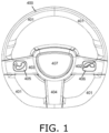
- FIG. 1 is a simplified illustration of a prior art steering wheel.
- FIG. 1 shows a steering wheel 400, including a circular grip 401, also known as a ring member, one or more connecting members 402 - 404 that connect grip 401 to steering column 407, and buttons 405 and 406 on connecting members 402 and 403; namely, button 405 is used to answer an incoming phone call on the vehicle's speaker phone, and button 406 hangs up the call.
- a circular grip 401 also known as a ring member
- connecting members 402 - 404 that connect grip 401 to steering column 407
- buttons 405 and 406 on connecting members 402 and 403 namely, button 405 is used to answer an incoming phone call on the vehicle's speaker phone, and button 406 hangs up the call.
- the computer mouse In contrast to user interfaces based on absolute positioning, the computer mouse introduced a user interface for controlling a cursor based on relative positioning. Namely, the mouse cursor moves on the screen in a direction that the mouse moves from point A to point B, but this movement is not at all contingent on the actual coordinates -- the absolute positions -- of points A and B.
- This shift from absolute positioning to relative positioning frees the user from having to look at, or be aware of, the location of the mouse on the table. The user only has to control the direction in which the mouse moves on the table, which he can do without looking at the mouse.
- One of the objectives of the present invention is to provide a user interface that does not require a driver to take his eyes off the road.
- Overhead consoles have multiple functions that are located in a confined space.
- the functions need to be easily identified by the user and intuitive in operation to keep the driver's attention on the road and must comply with federal regulations specifying design, construction, performance and durability requirements for motor vehicles and regulated components, systems and design features.
- Federal Motor Vehicle Safety Standards FMVSS
- CMS Motor Vehicle Safety Standards
- UN regulations developed by the World Forum for Harmonization of Vehicle Regulations.
- FMVSS No. 118 regulating window, partition and roof panel systems aims at preventing accidental operation, e.g., by a child, leg or knee.
- roof panel switches that can close a roof panel by momentary switch actuation must be protected from operation by a 20mm radius sphere which represents a knee or leg.
- FIG. 2 is an image of a prior art vehicle overhead console.
- FIG. 2 shows an overhead console 600 having map light 601, roof panel control 602 and slide switch 603 for controlling the vehicle's internal cabin light.
- the present invention relates to user interfaces for on-board vehicle systems, and teaches a user interface that does not require the user to look at the steering wheel in order to activate a function.
- the present invention teaches user gestures that can be mapped to a variety of applications.
- a steering wheel including a series of optoelectronic components mounted in the steering wheel grip, each specific optoelectronic component including a PCB, a light projector, having at least one light pulse emitter, mounted on the PCB, the light projector projecting light out of the steering wheel grip at two different angles, denoted a1 and a2, a light sensor, having at least one light detector mounted on the PCB, the light sensor detecting reflections of the light projected by the light pulse emitters of the optoelectronic components that neighbor the specific optoelectronic component on two opposite sides thereof, the light being reflected by an object above the steering wheel grip, a lens oriented relative to the light sensor in such a manner that the light sensor receives maximum intensity when light enters the lens at either of two particular angles, specifically, (i) the light sensor receives maximum intensity when the light reflected by the object enters the lens at a particular angle b1, and (ii) the light sensor also receives maximum
- a steering wheel including a series of optoelectronic components mounted in the steering wheel grip, each specific optoelectronic component including a PCB, at least two light pulse emitters mounted on the PCB for projecting light out of the steering wheel grip, at least two light detectors mounted on the PCB detecting reflections of the light projected by light pulse emitters of optoelectronic components on opposite sides of the specific optoelectronic component, the light being reflected by an object above the steering wheel grip, and a lens oriented relative to the light detectors in such a manner that each light detector receives maximum intensity when light enters the lens at a particular angle, specifically, (i) one or more of the light pulse emitters project light out of the steering wheel grip at an angle a1, (ii) one or more others of the light pulse emitters project light out of the steering wheel grip at an angle a2 different than a1, (iii) one or more of the light detectors receive maximum intensity when the light
- a method for detecting driver input by providing a series of optoelectronic components in a steering wheel grip, each specific optoelectronic component projecting light beams in two emission directions, denoted by angles a1 and a2, out of the steering wheel grip, and orienting a lens within each specific optoelectronic component so as to provide two viewing angles, denoted b1 and b2, that detect maximum intensity of reflections of the light projected by optoelectronic components that neighbor the specific optoelectronic component, the light being reflected by a reflective object above the steering wheel grip, wherein viewing angle b1 receives maximum intensity when light projected by a first neighboring optoelectronic component at angle a1 is reflected by the object, and viewing angle b2 receives maximum intensity when light projected by a second neighboring optoelectronic component at angle a2 is reflected by the object.
- aspects of the present invention relate to light-based touch and gesture controls that allow a driver to keep his hands on the steering wheel and eyes on the road while operating electronic devices and automated features in a vehicle.
- Detection of ergonomic gestures is enabled by the sensors described herein, and the invention includes methods of interacting with systems in the vehicle using the ergonomic gestures on the steering wheel.
- FIG. 3 is a simplified illustration of a steering wheel, in accordance with an embodiment of the present invention.
- FIG. 3 shows steering wheel 100.
- the upper-right segment of the steering wheel ring member has two concentric bands of proximity sensors, 180 and 181.
- each proximity sensor has a light emitter (not shown) that emits a directed light beam 160 outwards from the steering wheel, and a light detector (not shown) having a specific viewing angle 170.
- emitter beams and viewing angles are drawn using dashed lines.
- the emitter beams are drawn using longer dashes than the viewing angles.
- the proximity sensor light detector detects an object when light beam 160 is reflected back at the detector's specific viewing angle 170.
- FIG. 3 shows the intersection between each emitter beam 160 and a respective detector viewing angle 170.
- the intersection is the location at which an object will be maximally detected by the proximity sensor.
- the steering wheel's concentric bands of proximity sensors identify swipe gestures across the width of the steering wheel grip.
- Viewing angle 170 is also referred to as a corridor of maximum detection.
- FIGS. 4 and 5 are simplified illustrations of a thumb swipe gesture detected by a steering wheel, in accordance with an embodiment of the present invention.
- FIGS. 4 and 5 illustrate a swipe gesture performed by the driver's thumb of hand 190 gripping steering wheel 100.
- the driver's radially extended thumb is detected by inner band 181 of proximity sensors
- the driver's thumb is detected by outer band 180 of proximity sensors.
- This gesture is efficient and comfortable for the driver gripping the wheel, as the driver radially extends her thumb from the palm ( FIG. 4 ) and then adducts the thumb to sweep it upward across the width of the steering wheel ( FIG. 5 ).
- the reverse gesture -- abducting the thumb from the position in FIG. 5 to the position in FIG. 4 -- is also efficient and comfortable for the driver.
- Other gestures, such as moving a finger or hand along one of the bands 180 and 181, are also supported by embodiments of the present invention.
- FIG. 6 is a simplified illustration of the light beams and corridors of maximum light detection provided for a gesture-detecting steering wheel, in accordance with an embodiment of the present invention.
- FIG. 6 shows two complete concentric circles 180, 181 of proximity sensors along the grip of steering wheel 100.
- FIG. 7 is a simplified illustration of optoelectronic components mounted on a PCB in a steering wheel, in accordance with an embodiment of the present invention.
- FIG. 7 shows the steering wheel of FIG. 6 with the upper portion of the steering wheel grip removed to expose PCB 105 and a plurality of optoelectronic components 150 mounted upright on PCB 105; i.e., optoelectronic components 150 are oriented substantially perpendicular to PCB 105 and to the surface of the steering wheel grip facing the driver.
- Some steering wheel ring members include an inner ring made of a stiff material shaped into a bent or curved cross-section that strengthens the steering wheel ring, as illustrated therein in FIGS. 13A - 13N.
- optoelectronic components 150 are mounted between the walls formed by the bent or curved inner ring cross-section to protect optoelectronic components 150.
- Each optoelectronic component 150 includes a PCB, one or more emitters, one or more detectors and a lens that directs light beams 160 and creates viewing angles 170 for the detectors.
- the upper portion of the steering wheel grip not shown in FIG. 7 , is light-transmissive to enable beams 160 to travel out of steering wheel 100 and to enable reflections of beams 160 to reenter steering wheel 100 and reach the detectors.
- beams 160 pass through the opening in the bent or curved cross-section.
- FIG. 8 is the illustration of FIG. 7 with the addition of light beams and corridors of maximum light detection provided for a gesture-detecting steering wheel, in accordance with an embodiment of the present invention.
- FIG. 8 shows the steering wheel of FIG. 7 , optoelectronic components 150 and the light beams and viewing angles that enable the proximity sensors to detect objects.
- FIG. 8 shows the two concentric bands 180 and 181 of proximity sensors by illustrating intersections between emitter beams and viewing angles for all of the optoelectronic components.
- FIGS. 9 - 11 are simplified illustrations of optoelectronic components mounted in a segment of a steering wheel, in accordance with an embodiment of the present invention.
- FIGS. 9 - 11 show a portion of steering wheel 100 without its upper surface, exposing PCB 105 and six or seven optoelectronic components 150.
- the emitter beams 160 and detector viewing angles 170 for each optoelectronic component 150 are shown.
- the intersection between each emitter beam 160 and the viewing angle 170 of a corresponding detector is the location at which an object, reflecting beam 160, is detected.
- Each optoelectronic component 150 in FIGS. 9 - 11 has two emitter beams and two detector viewing angles.
- the emitter beams are projected out of the component at divergent angles, denoted a1 and a2, and the viewing angles are denoted b1 and b2 .
- Projection angles a1 and a2 and viewing angles b1 and b2 are shown in FIG. 13 .
- FIGS. 9 - 11 also show that the two emitter beams of optoelectronic component n are intersected by the viewing angles of optoelectronic component n-1 and optoelectronic component n+1, respectively. This relationship between neighboring optoelectronic components is further illustrated in FIG. 12 .
- FIG. 12 is a simplified illustration of two optoelectronic components in a steering wheel, in accordance with an embodiment of the present invention.
- FIG. 12 shows two, neighboring optoelectronic components 151 and 152 mounted on PCB 105.
- Optoelectronic component 151 projects emitter beams 161 and 162 and detects light arriving at viewing angles 171 and 172.
- Optoelectronic component 152 projects emitter beams 163 and 164 and detects light arriving at viewing angles 173 and 174.
- a location along an emitter beam that is located along the viewing angle of a detector is referred to as a "hotspot". Reflections of the light beam by an object at this location are maximally detected by the detector.
- the hotspots are located at, or near, the outer surface of the steering wheel grip facing the driver. In other embodiments of the invention, the hotspots are located in airspace above the outer surface of the steering wheel grip facing the driver. In still other embodiments of the invention, some of the hotspots are nearer to the steering wheel grip than others.
- Two hotspots 182 and 183 are indicated in FIG. 12 .
- Hotspot 183 is at the intersection of emitter beam 163 and viewing angle 171.
- Hotspot 182 is at the intersection of emitter beam 162 and viewing angle 173.
- Hotspot 183 is located along outer band 180 of the proximity sensors in FIGS.
- hotspot 182 is located along inner band 181 of the proximity sensors in FIGS. 3-6 .
- the concentric bands or arcs of the proximity sensors in FIGS. 3-6 are actually hotspots created by the emitters and detectors of optoelectronic components 150.
- the two emitter beams emitted by each optoelectronic component define a first plane, and the two viewing angles of that same optoelectronic component define a second plane that intersects the first plane. This is illustrated in FIG. 13 .
- FIG. 13 is a simplified illustration of an optoelectronic component, in accordance with an embodiment of the present invention.
- FIG. 13 illustrates a single optoelectronic component.
- FIG. 13 shows two optical parts 120 and 121 separated by air.
- a single emitter e.g., a vertical cavity surface-emitting laser (VCSEL) or a light-emitting diode (LED)
- VCSEL vertical cavity surface-emitting laser
- LED light-emitting diode
- a single photodiode detector is mounted underneath optical part 121.
- the combination of lenses and air-to-plastic surfaces in optical parts 120 and 121 provides two viewing angles 171 and 172 to this single photodiode detector.
- each light beam is generated by a separate light emitter.
- a separate detector is provided for each viewing angle.
- each light beam is generated by a separate light emitter and a separate detector is provided for each viewing angle.
- FIG. 14 is an exploded view of the optoelectronic component of FIG. 13 , in accordance with an embodiment of the present invention.
- FIG. 14 shows emitter 110 and photodiode detector 115 mounted on PCB 106, covered by optical parts 120 and 121.
- optical parts 120 and 121 are molded as a single part that is mounted on PCB 106.
- each viewing angle can be configured to intersect two emitter beams emitted by two respective optoelectronic components.
- These two hotspots are at different heights above the steering wheel grip, and enable detecting when the driver's hand approaches the steering wheel grip, namely, the further hotspot detects the hand first, and the nearer hotspot detects the hand second.
- the nearer hotspot is formed by the detector on optoelectronic component n detecting a light beam emitted by optoelectronic component n+1
- the further hotspot is formed by the detector on optoelectronic component n detecting a light beam emitted by optoelectronic component n+2.
- Certain proximity sensors provide a large array of light emitters and light detectors mounted on a single PCB. This configuration requires that each emitter and each detector be placed precisely on the PCB so that they are positioned correctly in relation to their respective lenses.
- a long PCB may suffer from significant bending or warping when exposed to heat, causing a misalignment between the lenses and the components.
- embodiments of the present invention use multiple PCBs, and mount a small number of emitters and detectors on each PCB, e.g., only one or two emitters and only one or two detectors.
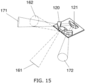
- FIG. 15 is a simplified illustration of the optoelectronic component of FIG. 12 viewed from a different perspective, in accordance with an embodiment of the present invention.
- FIG. 15 is a perspective view from above of the optoelectronic component of FIG. 13 .
- the outer surface (near the viewer) of the central portion of optical part 120 has two inclined surfaces that direct light in the two directions 161 and 162.
- One option is to provide one or more rigid, main PCBs 105 along the entire steering wheel grip, and soldering or otherwise connecting each optoelectronic component's PCB 106 to the underlying rigid PCB 105.
- a second option is to use a rigid-flex PCB, where individual optoelectronic component PCBs 106 are connected by flexible circuit substrates, and no PCB 105 is required.
- the output signals from the optoelectronic components 150 are typically weak signals and therefore the connector between optoelectronic components may need to be shielded.
Landscapes
- Engineering & Computer Science (AREA)
- Theoretical Computer Science (AREA)
- General Engineering & Computer Science (AREA)
- Mechanical Engineering (AREA)
- Chemical & Material Sciences (AREA)
- Combustion & Propulsion (AREA)
- Transportation (AREA)
- General Physics & Mathematics (AREA)
- Physics & Mathematics (AREA)
- Human Computer Interaction (AREA)
- User Interface Of Digital Computer (AREA)
- Steering Controls (AREA)
- Switches Operated By Changes In Physical Conditions (AREA)
- Position Input By Displaying (AREA)
Description
- The field of the present invention is user interfaces for motorists and passengers, via the steering wheel in a vehicle.
- Prior art user interfaces on steering wheels associate a function with an absolute position on the steering wheel. This is conceptually analogous to a touch-sensitive screen displaying icons where the user touches the location on the screen at which the icon is located to activate the icon. Such concepts are disclosed in the
EP 2 937 263 A2 ,JP 2010 088487 A US 2014/081521 A1 . - Reference is made to
FIG. 1 , which is a simplified illustration of a prior art steering wheel.FIG. 1 shows asteering wheel 400, including acircular grip 401, also known as a ring member, one or more connecting members 402 - 404 that connectgrip 401 tosteering column 407, andbuttons members button 405 is used to answer an incoming phone call on the vehicle's speaker phone, andbutton 406 hangs up the call. - In contrast to user interfaces based on absolute positioning, the computer mouse introduced a user interface for controlling a cursor based on relative positioning. Namely, the mouse cursor moves on the screen in a direction that the mouse moves from point A to point B, but this movement is not at all contingent on the actual coordinates -- the absolute positions -- of points A and B. This shift from absolute positioning to relative positioning frees the user from having to look at, or be aware of, the location of the mouse on the table. The user only has to control the direction in which the mouse moves on the table, which he can do without looking at the mouse. One of the objectives of the present invention is to provide a user interface that does not require a driver to take his eyes off the road.
- Overhead consoles have multiple functions that are located in a confined space. The functions need to be easily identified by the user and intuitive in operation to keep the driver's attention on the road and must comply with federal regulations specifying design, construction, performance and durability requirements for motor vehicles and regulated components, systems and design features. In the United States these regulations are contained in the Federal Motor Vehicle Safety Standards (FMVSS), in Canada in the Canada Motor Vehicle Safety Standards (CMVSS), and other countries have adopted UN regulations developed by the World Forum for Harmonization of Vehicle Regulations. FMVSS No. 118 regulating window, partition and roof panel systems, aims at preventing accidental operation, e.g., by a child, leg or knee. Thus, for example, roof panel switches that can close a roof panel by momentary switch actuation must be protected from operation by a 20mm radius sphere which represents a knee or leg.
- Reference is made to
FIG. 2 , which is an image of a prior art vehicle overhead console.FIG. 2 shows anoverhead console 600 havingmap light 601,roof panel control 602 andslide switch 603 for controlling the vehicle's internal cabin light. - The present invention relates to user interfaces for on-board vehicle systems, and teaches a user interface that does not require the user to look at the steering wheel in order to activate a function. The present invention teaches user gestures that can be mapped to a variety of applications.
- There is thus provided in accordance with an embodiment of the present invention a steering wheel including a series of optoelectronic components mounted in the steering wheel grip, each specific optoelectronic component including a PCB, a light projector, having at least one light pulse emitter, mounted on the PCB, the light projector projecting light out of the steering wheel grip at two different angles, denoted a1 and a2, a light sensor, having at least one light detector mounted on the PCB, the light sensor detecting reflections of the light projected by the light pulse emitters of the optoelectronic components that neighbor the specific optoelectronic component on two opposite sides thereof, the light being reflected by an object above the steering wheel grip, a lens oriented relative to the light sensor in such a manner that the light sensor receives maximum intensity when light enters the lens at either of two particular angles, specifically, (i) the light sensor receives maximum intensity when the light reflected by the object enters the lens at a particular angle b1, and (ii) the light sensor also receives maximum intensity when light reflected by the object enters the lens at a particular angle b2 different than b1, wherein angle b1 views reflections of light projected at angle a1 by the light projector of the optoelectronic component neighboring the specific optoelectronic component on one side, and angle b2 views reflections of light projected at angle a2 by the light projector of the optoelectronic component neighboring the specific optoelectronic component on the side opposite the one side.
- There is additionally provided, in accordance with an embodiment of the present invention, a steering wheel including a series of optoelectronic components mounted in the steering wheel grip, each specific optoelectronic component including a PCB, at least two light pulse emitters mounted on the PCB for projecting light out of the steering wheel grip, at least two light detectors mounted on the PCB detecting reflections of the light projected by light pulse emitters of optoelectronic components on opposite sides of the specific optoelectronic component, the light being reflected by an object above the steering wheel grip, and a lens oriented relative to the light detectors in such a manner that each light detector receives maximum intensity when light enters the lens at a particular angle, specifically, (i) one or more of the light pulse emitters project light out of the steering wheel grip at an angle a1, (ii) one or more others of the light pulse emitters project light out of the steering wheel grip at an angle a2 different than a1, (iii) one or more of the light detectors receive maximum intensity when the light reflected by the object enters the lens at a particular angle b1, and (iv) one or more others of the light detectors receive maximum intensity when light reflected by the object enters the lens at a particular angle b2 different than b1.
- There is further provided, in accordance with an embodiment of the present invention, a method for detecting driver input by providing a series of optoelectronic components in a steering wheel grip, each specific optoelectronic component projecting light beams in two emission directions, denoted by angles a1 and a2, out of the steering wheel grip, and orienting a lens within each specific optoelectronic component so as to provide two viewing angles, denoted b1 and b2, that detect maximum intensity of reflections of the light projected by optoelectronic components that neighbor the specific optoelectronic component, the light being reflected by a reflective object above the steering wheel grip, wherein viewing angle b1 receives maximum intensity when light projected by a first neighboring optoelectronic component at angle a1 is reflected by the object, and viewing angle b2 receives maximum intensity when light projected by a second neighboring optoelectronic component at angle a2 is reflected by the object.
- The present invention will be more fully understood and appreciated from the following detailed description, taken in conjunction with the drawings in which:
-
FIG. 1 is a simplified illustration of a prior art steering wheel; -
FIG. 2 is an image of a prior art vehicle overhead console; -
FIG. 3 is a simplified illustration of a steering wheel, in accordance with an embodiment of the present invention; -
FIGS. 4 and5 are simplified illustrations of a thumb swipe gesture detected by a steering wheel, in accordance with an embodiment of the present invention; -
FIG. 6 is a simplified illustration of the light beams and corridors of maximum light detection provided for a gesture-detecting steering wheel, in accordance with an embodiment of the present invention; -
FIG. 7 is a simplified illustration of optoelectronic components mounted on a PCB in a steering wheel, in accordance with an embodiment of the present invention; -
FIG. 8 is the illustration ofFIG. 7 with the addition of light beams and corridors of maximum light detection provided for a gesture-detecting steering wheel, in accordance with an embodiment of the present invention; -
FIGS. 9 - 11 are simplified illustrations of optoelectronic components mounted in a segment of a steering wheel, in accordance with an embodiment of the present invention; -
FIG. 12 is a simplified illustration of two optoelectronic components in a steering wheel, in accordance with an embodiment of the present invention; -
FIG. 13 is a simplified illustration of an optoelectronic component, in accordance with an embodiment of the present invention; -
FIG. 14 is an exploded view of the optoelectronic component ofFIG. 13 , in accordance with an embodiment of the present invention; -
FIG. 15 is a simplified illustration of the optoelectronic component ofFIG. 13 viewed from a different perspective, in accordance with an embodiment of the present invention; - In the disclosure and figures, the following numbering scheme is used. Like numbered elements are similar but not necessarily identical.
Type of element Numbering range steering wheel 100 - 104 PCB 105 - 109 light emitter 110 - 114 light detector 115 - 119 lens or optical part 120 - 129 optoelectronic component 150 - 159 outgoing light beam 160 - 169 viewing angle 170 - 179 hotspot 180 - 189 hand 190 - 199 prior art elements 400 - 410 prior art vehicle overhead console 600 map light 601 roof panel control 602 cabin light slide switch 603 touchscreen display 604 map light icon 605 - 607 open/close sunroof icon 608 sunroof pop-up vent icon 609 open/close moonroof icon 610 finger 611 fingers 612 in-air detection plane 613 movement direction arrows 614 vehicle interior roof 615 rearview mirror 616 front windshield 617 - Aspects of the present invention relate to light-based touch and gesture controls that allow a driver to keep his hands on the steering wheel and eyes on the road while operating electronic devices and automated features in a vehicle. Detection of ergonomic gestures is enabled by the sensors described herein, and the invention includes methods of interacting with systems in the vehicle using the ergonomic gestures on the steering wheel.
- Reference is made to
FIG. 3 , which is a simplified illustration of a steering wheel, in accordance with an embodiment of the present invention.FIG. 3 showssteering wheel 100. The upper-right segment of the steering wheel ring member has two concentric bands of proximity sensors, 180 and 181. InFIG. 3 each proximity sensor has a light emitter (not shown) that emits a directedlight beam 160 outwards from the steering wheel, and a light detector (not shown) having aspecific viewing angle 170. In the figures, emitter beams and viewing angles are drawn using dashed lines. The emitter beams are drawn using longer dashes than the viewing angles. The proximity sensor light detector detects an object whenlight beam 160 is reflected back at the detector'sspecific viewing angle 170.FIG. 3 shows the intersection between eachemitter beam 160 and a respectivedetector viewing angle 170. The intersection is the location at which an object will be maximally detected by the proximity sensor. The steering wheel's concentric bands of proximity sensors identify swipe gestures across the width of the steering wheel grip.Viewing angle 170 is also referred to as a corridor of maximum detection. - Reference is made to
FIGS. 4 and5 , which are simplified illustrations of a thumb swipe gesture detected by a steering wheel, in accordance with an embodiment of the present invention.FIGS. 4 and5 illustrate a swipe gesture performed by the driver's thumb ofhand 190 grippingsteering wheel 100. InFIG. 4 the driver's radially extended thumb is detected byinner band 181 of proximity sensors, and inFIG. 5 the driver's thumb is detected byouter band 180 of proximity sensors. This gesture is efficient and comfortable for the driver gripping the wheel, as the driver radially extends her thumb from the palm (FIG. 4 ) and then adducts the thumb to sweep it upward across the width of the steering wheel (FIG. 5 ). The reverse gesture -- abducting the thumb from the position inFIG. 5 to the position inFIG. 4 -- is also efficient and comfortable for the driver. Other gestures, such as moving a finger or hand along one of thebands - Reference is made to
FIG. 6 , which is a simplified illustration of the light beams and corridors of maximum light detection provided for a gesture-detecting steering wheel, in accordance with an embodiment of the present invention.FIG. 6 shows two completeconcentric circles steering wheel 100. - Reference is made to
FIG. 7 , which is a simplified illustration of optoelectronic components mounted on a PCB in a steering wheel, in accordance with an embodiment of the present invention.FIG. 7 shows the steering wheel ofFIG. 6 with the upper portion of the steering wheel grip removed to exposePCB 105 and a plurality ofoptoelectronic components 150 mounted upright onPCB 105; i.e.,optoelectronic components 150 are oriented substantially perpendicular toPCB 105 and to the surface of the steering wheel grip facing the driver. Some steering wheel ring members include an inner ring made of a stiff material shaped into a bent or curved cross-section that strengthens the steering wheel ring, as illustrated therein in FIGS. 13A - 13N. In certain embodiments of the invention,optoelectronic components 150 are mounted between the walls formed by the bent or curved inner ring cross-section to protectoptoelectronic components 150. Eachoptoelectronic component 150 includes a PCB, one or more emitters, one or more detectors and a lens that directslight beams 160 and creates viewing angles 170 for the detectors. The upper portion of the steering wheel grip, not shown inFIG. 7 , is light-transmissive to enablebeams 160 to travel out ofsteering wheel 100 and to enable reflections ofbeams 160 to reentersteering wheel 100 and reach the detectors. Whenoptoelectronic components 150 are mounted between the walls formed by the bent or curved inner ring cross-section, beams 160 pass through the opening in the bent or curved cross-section. - Reference is made to
FIG. 8 , which is the illustration ofFIG. 7 with the addition of light beams and corridors of maximum light detection provided for a gesture-detecting steering wheel, in accordance with an embodiment of the present invention.FIG. 8 shows the steering wheel ofFIG. 7 ,optoelectronic components 150 and the light beams and viewing angles that enable the proximity sensors to detect objects.FIG. 8 shows the twoconcentric bands - Reference is made to
FIGS. 9 - 11 , which are simplified illustrations of optoelectronic components mounted in a segment of a steering wheel, in accordance with an embodiment of the present invention.FIGS. 9 - 11 show a portion ofsteering wheel 100 without its upper surface, exposingPCB 105 and six or sevenoptoelectronic components 150. The emitter beams 160 and detector viewing angles 170 for eachoptoelectronic component 150 are shown. The intersection between eachemitter beam 160 and theviewing angle 170 of a corresponding detector is the location at which an object, reflectingbeam 160, is detected. Eachoptoelectronic component 150 inFIGS. 9 - 11 has two emitter beams and two detector viewing angles. The emitter beams are projected out of the component at divergent angles, denoted a1 and a2, and the viewing angles are denoted b1 and b2. Projection angles a1 and a2 and viewing angles b1 and b2 are shown inFIG. 13 .FIGS. 9 - 11 also show that the two emitter beams of optoelectronic component n are intersected by the viewing angles of optoelectronic component n-1 and optoelectronic component n+1, respectively. This relationship between neighboring optoelectronic components is further illustrated inFIG. 12 . - Reference is made to
FIG. 12 , which is a simplified illustration of two optoelectronic components in a steering wheel, in accordance with an embodiment of the present invention.FIG. 12 shows two, neighboringoptoelectronic components PCB 105.Optoelectronic component 151 projects emitterbeams viewing angles Optoelectronic component 152 projects emitterbeams viewing angles hotspots FIG. 12 .Hotspot 183 is at the intersection ofemitter beam 163 andviewing angle 171.Hotspot 182 is at the intersection ofemitter beam 162 andviewing angle 173.Hotspot 183 is located alongouter band 180 of the proximity sensors inFIGS. 3 - 6 , andhotspot 182 is located alonginner band 181 of the proximity sensors inFIGS. 3-6 . Thus the concentric bands or arcs of the proximity sensors inFIGS. 3-6 are actually hotspots created by the emitters and detectors ofoptoelectronic components 150. The two emitter beams emitted by each optoelectronic component define a first plane, and the two viewing angles of that same optoelectronic component define a second plane that intersects the first plane. This is illustrated inFIG. 13 . - Reference is made to
FIG. 13 , which is a simplified illustration of an optoelectronic component, in accordance with an embodiment of the present invention.FIG. 13 illustrates a single optoelectronic component. The twoemitter beams viewing angles -
FIG. 13 shows twooptical parts optical part 120 and its light is split intobeams optical part 121. The combination of lenses and air-to-plastic surfaces inoptical parts viewing angles - Reference is made to
FIG. 14 , which is an exploded view of the optoelectronic component ofFIG. 13 , in accordance with an embodiment of the present invention.FIG. 14 shows emitter 110 andphotodiode detector 115 mounted onPCB 106, covered byoptical parts optical parts PCB 106. - Referring back to
FIGS. 9 - 11 , it can be seen that each viewing angle can be configured to intersect two emitter beams emitted by two respective optoelectronic components. These two hotspots are at different heights above the steering wheel grip, and enable detecting when the driver's hand approaches the steering wheel grip, namely, the further hotspot detects the hand first, and the nearer hotspot detects the hand second. The nearer hotspot is formed by the detector on optoelectronic component n detecting a light beam emitted by optoelectronic component n+1, and the further hotspot is formed by the detector on optoelectronic component n detecting a light beam emitted by optoelectronic component n+2. - Certain proximity sensors provide a large array of light emitters and light detectors mounted on a single PCB. This configuration requires that each emitter and each detector be placed precisely on the PCB so that they are positioned correctly in relation to their respective lenses. However, a long PCB may suffer from significant bending or warping when exposed to heat, causing a misalignment between the lenses and the components. Furthermore, when one lens part is used for more than one component, it may be difficult to position the lens part correctly. In order to overcome these problems, embodiments of the present invention use multiple PCBs, and mount a small number of emitters and detectors on each PCB, e.g., only one or two emitters and only one or two detectors.
- Reference is made to
FIG. 15 , which is a simplified illustration of the optoelectronic component ofFIG. 12 viewed from a different perspective, in accordance with an embodiment of the present invention.FIG. 15 is a perspective view from above of the optoelectronic component ofFIG. 13 . The outer surface (near the viewer) of the central portion ofoptical part 120 has two inclined surfaces that direct light in the twodirections - Several options are available for connecting the optoelectronic components to each other. One option is to provide one or more rigid,
main PCBs 105 along the entire steering wheel grip, and soldering or otherwise connecting each optoelectronic component'sPCB 106 to the underlyingrigid PCB 105. A second option is to use a rigid-flex PCB, where individualoptoelectronic component PCBs 106 are connected by flexible circuit substrates, and noPCB 105 is required. The output signals from theoptoelectronic components 150 are typically weak signals and therefore the connector between optoelectronic components may need to be shielded.
Claims (15)
- A steering wheel (100) comprising a series of optoelectronic components (150 - 152) mounted in the steering wheel grip, each specific optoelectronic component comprising:a PCB (106);a light projector, comprising at least one light pulse emitter (110) mounted on said PCB, the light projector projecting light (160-164) out of said steering wheel grip at two different angles relative to the plane of the steering grip, denoted a1 and a2;a light sensor, comprising at least one light detector(115) mounted on said PCB, the light sensor detecting reflections of the light projected by the light projectors of the optoelectronic components that neighbor the specific optoelectronic component on two opposite sides thereof, the light being reflected by an object above the steering wheel grip; anda lens (120, 121) oriented relative to said light sensor,characterized in thatthe lens (120, 121) is oriented relative to said light sensor in such a manner that said light sensor receives maximum intensity when light enters the lens at either of two particular angles, specifically, said light sensor receives maximum intensity when the light reflected by the object enters the lens at a particular angle b1 relative to the plane of the steering grip, and said light sensor also receives maximum intensity when light reflected by the object enters the lens at a particular angle b2 relative to the plane of the steering grip, b2 being different than b1,wherein reflections of light projected at angle a1 by the light projector of the optoelectronic component neighboring the specific optoelectronic component on one side enter the lens at angle b1, and reflections of light projected at angle a2 by the light projector of the optoelectronic component neighboring the specific optoelectronic component on the side opposite the one side enter the lens at angle b2.
- The steering wheel of claim 1, wherein reflections of light projected at angle a1 by two optoelectronic components positioned on one side of the specific optoelectronic component enter the lens at angle b1.
- The steering wheel of claim 1, wherein said light projector comprises a beam splitter (120) that splits light from the at least one light pulse emitter to light projected out of the steering wheel grip at angles a1 and a2.
- The steering wheel of claim 1, wherein said light projector comprises a first light pulse emitter that projects light out of the steering wheel grip at angle a1, and a second light pulse emitter that projects light out of the steering wheel grip at angle a2.
- The steering wheel of claim 1, wherein each of the at least one light pulse detector receives maximum intensity when the light reflected by the object enters said lens at angle b1, and also receives maximum intensity when light reflected by the object enters said lens at angle b2.
- The steering wheel of claim 1, wherein said light sensor comprises a first light detector that receives maximum intensity when the light reflected by the object enters said lens at angle b1, and a second light detector that receives maximum intensity when light reflected by the object enters said lens at angle b2.
- The steering wheel of claim 1, further comprising a processor, connected to said optoelectronic components, configured to identify a swipe gesture by the object in a first direction across the steering wheel grip in response to a specific optoelectronic component detecting maximum intensity of reflections of the object at one of angles b1 and b2, followed by the specific optoelectronic component detecting maximum intensity of reflections of the object at the other of angles b1 and b2.
- The steering wheel of claim 1, further comprising a processor, connected to said optoelectronic components, configured to identify a swipe gesture by the object in a first direction across the steering wheel grip in response to a first specific optoelectronic component detecting maximum intensity of reflections of the object at one of angles b1 and b2, followed by a second optoelectronic component, neighboring the first optoelectronic component, detecting maximum intensity of reflections of the object at the other of angles b1 and b2.
- The steering wheel of claim 8, wherein said processor is further configured to identify a swipe gesture by the object in a second direction across the steering wheel grip in response to the first specific optoelectronic component detecting maximum intensity of reflections of the object at one of angles b1 and b2, followed by the second optoelectronic component detecting maximum intensity of reflections of the object at the same one of angles b1 and b2.
- The steering wheel of claim 1, further comprising a processor, connected to said optoelectronic components, configured to identify an approach gesture by the object toward the steering wheel grip in response to a specific optoelectronic component detecting maximum intensity of reflections of light projected by the light projector of a first neighboring optoelectronic component at one of angles b1 and b2, followed by detecting maximum intensity of reflections of light projected by the light projector of a second neighboring optoelectronic component at the same one of angles b1 and b2, wherein the second neighboring optoelectronic component is nearer to the specific optoelectronic component than is the first neighboring optoelectronic component.
- The steering wheel of claim 1, wherein said PCB is oriented substantially perpendicular to the surface of the steering wheel grip facing the driver.
- A method for detecting driver input, comprising:providing a series of optoelectronic components (150-152) in a steering wheel grip (100), each specific optoelectronic component including a light emitter (110) and a light detector (115), wherein the light emitter projects light beams (160-164) in two emission directions out of the steering wheel grip, at angles a1 and a2 relative to the plane of the steering wheel grip;orienting a lens (120, 121) within each specific optoelectronic component such that the specific optoelectronic component light detector detects maximum intensity of reflections of the light projected by optoelectronic components that neighbor the specific optoelectronic component when the reflected light enters the lens at angles b1 and b2, the light being reflected by an object above the steering wheel grip; andmapping driver input to locations along the steering wheel grip that correspond to detections of the reflections.
- The method of claim 12, further comprising identifying an approach gesture by the object in response to detecting reflections of light projected by a distant neighboring optoelectronic component followed by detecting reflections of light projected by a near neighboring optoelectronic component.
- The method of claim 12, further comprising identifying a radial swipe gesture by the object in a first direction across the steering wheel grip in response to detecting reflections of the object entering the lens at angle b1 followed by detecting reflections of the object entering the lens at angle b2.
- The method of claim 14, further comprising identifying a swipe gesture by the object in a second direction across the steering wheel grip in response to a first optoelectronic component detecting reflections of the object entering the lens at one of angles b1 and b2, followed by a second optoelectronic component, neighboring the first optoelectronic component, detecting reflections of the object entering the lens at the same one of angles b1 and b2.
Applications Claiming Priority (3)
| Application Number | Priority Date | Filing Date | Title |
|---|---|---|---|
| US201862772574P | 2018-11-28 | 2018-11-28 | |
| US201862778390P | 2018-12-12 | 2018-12-12 | |
| PCT/US2019/062909 WO2020112585A1 (en) | 2018-11-28 | 2019-11-25 | Motorist user interface sensor |
Publications (4)
| Publication Number | Publication Date |
|---|---|
| EP3887192A1 EP3887192A1 (en) | 2021-10-06 |
| EP3887192A4 EP3887192A4 (en) | 2021-12-22 |
| EP3887192C0 EP3887192C0 (en) | 2023-06-07 |
| EP3887192B1 true EP3887192B1 (en) | 2023-06-07 |
Family
ID=70854107
Family Applications (1)
| Application Number | Title | Priority Date | Filing Date |
|---|---|---|---|
| EP19890109.2A Active EP3887192B1 (en) | 2018-11-28 | 2019-11-25 | Motorist user interface sensor |
Country Status (4)
| Country | Link |
|---|---|
| US (1) | US11429230B2 (en) |
| EP (1) | EP3887192B1 (en) |
| CN (1) | CN113165515B (en) |
| WO (1) | WO2020112585A1 (en) |
Families Citing this family (3)
| Publication number | Priority date | Publication date | Assignee | Title |
|---|---|---|---|---|
| US10953791B2 (en) * | 2018-03-08 | 2021-03-23 | Joyson Safety Systems Acquisition Llc | Vehicle illumination systems and methods |
| US11921936B2 (en) * | 2021-10-22 | 2024-03-05 | Hyundai Mobis Co., Ltd. | Vehicle function operation apparatus and method |
| DE102021132228A1 (en) | 2021-12-08 | 2023-06-15 | Dr. Ing. H.C. F. Porsche Aktiengesellschaft | motor vehicle |
Family Cites Families (221)
| Publication number | Priority date | Publication date | Assignee | Title |
|---|---|---|---|---|
| GB1107666A (en) | 1966-03-30 | 1968-03-27 | Cosmic Car Accessories Ltd | Steering wheels |
| US4267443A (en) | 1978-04-24 | 1981-05-12 | Carroll Manufacturing Corporation | Photoelectric input apparatus |
| US4243879A (en) | 1978-04-24 | 1981-01-06 | Carroll Manufacturing Corporation | Touch panel with ambient light sampling |
| US4301447A (en) | 1979-12-12 | 1981-11-17 | Sperry Corporation | Scan control for light beam position indicator |
| JPS59100430A (en) | 1982-11-30 | 1984-06-09 | Minolta Camera Co Ltd | Original lighting reflecting mirror of copying machine |
| US4550250A (en) | 1983-11-14 | 1985-10-29 | Hei, Inc. | Cordless digital graphics input device |
| US5003505A (en) | 1984-05-07 | 1991-03-26 | Hewlett-Packard Company | Touchscreen/keyboard scanner |
| DE3579122D1 (en) | 1984-06-18 | 1990-09-13 | Amp Inc | TOUCH ACTIVE INPUT DEVICE. |
| EP0183785B1 (en) | 1984-06-18 | 1991-08-28 | Carroll Touch Incorporated | Touch input device having digital ambient light sampling |
| US4703316A (en) | 1984-10-18 | 1987-10-27 | Tektronix, Inc. | Touch panel input apparatus |
| US4710760A (en) | 1985-03-07 | 1987-12-01 | American Telephone And Telegraph Company, At&T Information Systems Inc. | Photoelastic touch-sensitive screen |
| US4880969A (en) | 1986-04-30 | 1989-11-14 | Litton Systems, Inc. | Optical touch panel with heat sink |
| US4790028A (en) | 1986-09-12 | 1988-12-06 | Westinghouse Electric Corp. | Method and apparatus for generating variably scaled displays |
| US4782328A (en) | 1986-10-02 | 1988-11-01 | Product Development Services, Incorporated | Ambient-light-responsive touch screen data input method and system |
| JPS63172325A (en) | 1987-01-10 | 1988-07-16 | Pioneer Electronic Corp | Touch panel controller |
| FR2615941B1 (en) | 1987-05-25 | 1991-12-06 | Sfena | DEVICE FOR DETECTING THE POSITION OF A CONTROL MEMBER ON A TOUCH TABLET |
| US4847606A (en) | 1987-08-25 | 1989-07-11 | Oak Industries Inc. | Control and display system |
| US4928094A (en) | 1988-01-25 | 1990-05-22 | The Boeing Company | Battery-operated data collection apparatus having an infrared touch screen data entry device |
| US5053758A (en) | 1988-02-01 | 1991-10-01 | Sperry Marine Inc. | Touchscreen control panel with sliding touch control |
| JPH01314324A (en) | 1988-06-14 | 1989-12-19 | Sony Corp | Touch panel device |
| US5220409A (en) | 1988-12-19 | 1993-06-15 | Amp Incorporated | Light beam detection utilizing hologram |
| US5194863A (en) | 1989-04-10 | 1993-03-16 | International Business Machines Corporation | Touch panel display |
| JPH081363B2 (en) | 1989-05-08 | 1996-01-10 | 同和鉱業株式会社 | Optical input detector |
| US5283558A (en) | 1989-10-16 | 1994-02-01 | Chan James K | Low-cost devices for touch control |
| JP2784825B2 (en) | 1989-12-05 | 1998-08-06 | ソニー株式会社 | Information input control device |
| US5179369A (en) | 1989-12-06 | 1993-01-12 | Dale Electronics, Inc. | Touch panel and method for controlling same |
| JPH03216719A (en) | 1990-01-22 | 1991-09-24 | Fujitsu Ltd | Position instruction device |
| US5162783A (en) | 1990-07-23 | 1992-11-10 | Akzo N.V. | Infrared touch screen device for a video monitor |
| US5103085A (en) | 1990-09-05 | 1992-04-07 | Zimmerman Thomas G | Photoelectric proximity detector and switch |
| US5119079A (en) | 1990-09-17 | 1992-06-02 | Xerox Corporation | Touch screen user interface with expanding touch locations for a reprographic machine |
| GB9108226D0 (en) | 1991-04-17 | 1991-06-05 | Philips Electronic Associated | Optical touch input device |
| JP3123558B2 (en) | 1991-05-09 | 2001-01-15 | ソニー株式会社 | Information input processing device and method |
| US5579035A (en) | 1991-07-05 | 1996-11-26 | Technomarket, L.P. | Liquid crystal display module |
| JPH05173699A (en) | 1991-12-20 | 1993-07-13 | Fujitsu Ltd | Coordinate input device |
| US5889236A (en) | 1992-06-08 | 1999-03-30 | Synaptics Incorporated | Pressure sensitive scrollbar feature |
| GB2268263A (en) | 1992-06-30 | 1994-01-05 | Ibm | Input device for a visual display unit |
| US5605406A (en) | 1992-08-24 | 1997-02-25 | Bowen; James H. | Computer input devices with light activated switches and light emitter protection |
| US5422494A (en) | 1992-10-16 | 1995-06-06 | The Scott Fetzer Company | Barrier transmission apparatus |
| JPH0639621U (en) | 1992-10-30 | 1994-05-27 | 日本精機株式会社 | Vehicle switch device |
| US5612719A (en) | 1992-12-03 | 1997-03-18 | Apple Computer, Inc. | Gesture sensitive buttons for graphical user interfaces |
| EP0601651A1 (en) | 1992-12-10 | 1994-06-15 | Koninklijke Philips Electronics N.V. | Optical touch tablet based on sector cross bearing |
| US5463725A (en) | 1992-12-31 | 1995-10-31 | International Business Machines Corp. | Data processing system graphical user interface which emulates printed material |
| DE69422323T2 (en) | 1993-04-01 | 2000-06-21 | Ibm | Dynamic adjustment device for touch indicator buttons |
| US5603053A (en) | 1993-05-10 | 1997-02-11 | Apple Computer, Inc. | System for entering data into an active application currently running in the foreground by selecting an input icon in a palette representing input utility |
| DE69432199T2 (en) | 1993-05-24 | 2004-01-08 | Sun Microsystems, Inc., Mountain View | Graphical user interface with methods for interfacing with remote control devices |
| US5956030A (en) | 1993-06-11 | 1999-09-21 | Apple Computer, Inc. | Computer system with graphical user interface including windows having an identifier within a control region on the display |
| DE4334800A1 (en) | 1993-10-13 | 1994-05-19 | Allhoff Cramer Adalbert | Car steering wheel - Has groups of switches incorporated into rim of wheel beneath covering material operating relays by infra-red transmission |
| US5559727A (en) | 1994-02-24 | 1996-09-24 | Quad Systems Corporation | Apparatus and method for determining the position of a component prior to placement |
| US5577733A (en) | 1994-04-08 | 1996-11-26 | Downing; Dennis L. | Targeting system |
| US7126583B1 (en) | 1999-12-15 | 2006-10-24 | Automotive Technologies International, Inc. | Interactive vehicle display system |
| US9513744B2 (en) | 1994-08-15 | 2016-12-06 | Apple Inc. | Control systems employing novel physical controls and touch screens |
| DE69524340T2 (en) | 1994-09-22 | 2002-08-14 | Aisin Aw Co | Touch display for an information entry system |
| GB9422911D0 (en) | 1994-11-14 | 1995-01-04 | Moonstone Technology Ltd | Capacitive touch detectors |
| US5880743A (en) | 1995-01-24 | 1999-03-09 | Xerox Corporation | Apparatus and method for implementing visual animation illustrating results of interactive editing operations |
| US5618232A (en) | 1995-03-23 | 1997-04-08 | Martin; John R. | Dual mode gaming device methods and systems |
| US5729250A (en) | 1995-05-08 | 1998-03-17 | International Business Machines Corporation | Front cover assembly for a touch sensitive device |
| JPH09146708A (en) | 1995-11-09 | 1997-06-06 | Internatl Business Mach Corp <Ibm> | Driving method for touch panel and touch input method |
| US5825352A (en) | 1996-01-04 | 1998-10-20 | Logitech, Inc. | Multiple fingers contact sensing method for emulating mouse buttons and mouse operations on a touch sensor pad |
| JPH09289606A (en) | 1996-04-23 | 1997-11-04 | Canon Inc | Image display device and camera controller |
| US5748185A (en) | 1996-07-03 | 1998-05-05 | Stratos Product Development Group | Touchpad with scroll and pan regions |
| DE19631502C1 (en) | 1996-08-03 | 1998-01-22 | Bosch Gmbh Robert | Steering wheel with optoelectronic sensor |
| US5943044A (en) | 1996-08-05 | 1999-08-24 | Interlink Electronics | Force sensing semiconductive touchpad |
| KR100206998B1 (en) | 1996-08-28 | 1999-07-01 | 이종수 | Depression recognition device and control method of matrix type touch panel |
| US5936615A (en) | 1996-09-12 | 1999-08-10 | Digital Equipment Corporation | Image-based touchscreen |
| JPH10105556A (en) | 1996-09-27 | 1998-04-24 | Sharp Corp | Electronic dictionary and information display method |
| JP3240941B2 (en) | 1996-11-18 | 2001-12-25 | 松下電器産業株式会社 | Hand gesture detection method and device |
| GB9625262D0 (en) | 1996-12-04 | 1997-01-22 | Autoliv Dev | Improvements in or relating to an air-bag arrangement |
| US6052279A (en) | 1996-12-05 | 2000-04-18 | Intermec Ip Corp. | Customizable hand-held computer |
| US5900875A (en) | 1997-01-29 | 1999-05-04 | 3Com Corporation | Method and apparatus for interacting with a portable computer system |
| US6031989A (en) | 1997-02-27 | 2000-02-29 | Microsoft Corporation | Method of formatting and displaying nested documents |
| US5914709A (en) | 1997-03-14 | 1999-06-22 | Poa Sana, Llc | User input device for a computer system |
| JPH10269012A (en) | 1997-03-28 | 1998-10-09 | Yazaki Corp | Touch panel controller and information display device using the same |
| US6310609B1 (en) | 1997-04-17 | 2001-10-30 | Nokia Mobile Phones Limited | User interface with guide lights |
| US6073036A (en) | 1997-04-28 | 2000-06-06 | Nokia Mobile Phones Limited | Mobile station with touch input having automatic symbol magnification function |
| GB2330752B (en) | 1997-10-24 | 2002-09-04 | Sony Uk Ltd | Audio processing |
| WO1999028811A1 (en) | 1997-12-04 | 1999-06-10 | Northern Telecom Limited | Contextual gesture interface |
| US7663607B2 (en) | 2004-05-06 | 2010-02-16 | Apple Inc. | Multipoint touchscreen |
| KR100595925B1 (en) | 1998-01-26 | 2006-07-05 | 웨인 웨스터만 | Method and apparatus for integrating manual input |
| JPH11232024A (en) | 1998-02-13 | 1999-08-27 | Alpine Electron Inc | Optical position detector |
| KR100405018B1 (en) | 1998-02-25 | 2003-11-07 | 샤프 가부시키가이샤 | Display device |
| US6356287B1 (en) | 1998-03-20 | 2002-03-12 | Nuvomedia, Inc. | Citation selection and routing feature for hand-held content display device |
| US6010061A (en) | 1998-03-27 | 2000-01-04 | Micron Custom Manufacturing Services Inc. | Reflow soldering method |
| KR100327209B1 (en) | 1998-05-12 | 2002-04-17 | 윤종용 | Software keyboard system using the drawing of stylus and method for recognizing keycode therefor |
| JP4033582B2 (en) | 1998-06-09 | 2008-01-16 | 株式会社リコー | Coordinate input / detection device and electronic blackboard system |
| US6369803B2 (en) | 1998-06-12 | 2002-04-09 | Nortel Networks Limited | Active edge user interface |
| US6346935B1 (en) | 1998-09-14 | 2002-02-12 | Matsushita Electric Industrial Co., Ltd. | Touch-sensitive tablet |
| US6820895B2 (en) | 1998-09-23 | 2004-11-23 | Vehicle Safety Systems, Inc. | Vehicle air bag minimum distance enforcement apparatus, method and system |
| US6246395B1 (en) | 1998-12-17 | 2001-06-12 | Hewlett-Packard Company | Palm pressure rejection method and apparatus for touchscreens |
| US6259436B1 (en) | 1998-12-22 | 2001-07-10 | Ericsson Inc. | Apparatus and method for determining selection of touchable items on a computer touchscreen by an imprecise touch |
| US6552719B2 (en) | 1999-01-07 | 2003-04-22 | Microsoft Corporation | System and method for automatically switching between writing and text input modes |
| US7469381B2 (en) | 2007-01-07 | 2008-12-23 | Apple Inc. | List scrolling and document translation, scaling, and rotation on a touch-screen display |
| DE19983911B4 (en) | 1999-01-27 | 2018-09-06 | Compumedics Sleep Pty. Ltd. | Wachsamkeitsüberwachungssystem |
| GB2388938B (en) | 1999-02-22 | 2004-03-17 | Nokia Corp | A communication terminal having a predictive editor application |
| US6529920B1 (en) | 1999-03-05 | 2003-03-04 | Audiovelocity, Inc. | Multimedia linking device and method |
| US6135494A (en) | 1999-04-21 | 2000-10-24 | Breed Automotive Technology Inc. | Occupant proximity sensor with horn switch |
| US6411283B1 (en) | 1999-05-20 | 2002-06-25 | Micron Technology, Inc. | Computer touch screen adapted to facilitate selection of features at edge of screen |
| JP2000348560A (en) | 1999-06-07 | 2000-12-15 | Tokai Rika Co Ltd | Determining method for touch operation position |
| JP3830121B2 (en) | 1999-06-10 | 2006-10-04 | 株式会社 ニューコム | Optical unit for object detection and position coordinate input device using the same |
| US6639584B1 (en) | 1999-07-06 | 2003-10-28 | Chuang Li | Methods and apparatus for controlling a portable electronic device using a touchpad |
| JP2001043022A (en) | 1999-07-30 | 2001-02-16 | Matsushita Electric Ind Co Ltd | Transparent touch panel and electronic equipment using the same |
| US7007239B1 (en) | 2000-09-21 | 2006-02-28 | Palm, Inc. | Method and apparatus for accessing a contacts database and telephone services |
| US6874683B2 (en) | 1999-10-08 | 2005-04-05 | Canon Kabushiki Kaisha | User programmable smart card interface system for an image album |
| US6757002B1 (en) | 1999-11-04 | 2004-06-29 | Hewlett-Packard Development Company, L.P. | Track pad pointing device with areas of specialized function |
| JP2001134382A (en) | 1999-11-04 | 2001-05-18 | Sony Corp | Graphic processor |
| US7020845B1 (en) | 1999-11-15 | 2006-03-28 | Gottfurcht Elliot A | Navigating internet content on a television using a simplified interface and a remote control |
| US7006077B1 (en) | 1999-11-30 | 2006-02-28 | Nokia Mobile Phones, Ltd. | Electronic device having touch sensitive slide |
| MXPA02005431A (en) | 1999-12-02 | 2003-02-12 | Elo Touchsystems Inc | Apparatus and method to improve resolution of infrared touch systems. |
| US6727917B1 (en) | 2000-01-06 | 2004-04-27 | Microsoft Corporation | User interface for palm-sized computing devices and method and apparatus for displaying the same |
| JP2001216069A (en) | 2000-02-01 | 2001-08-10 | Toshiba Corp | Operation inputting device and direction detecting method |
| GB2365676B (en) | 2000-02-18 | 2004-06-23 | Sensei Ltd | Mobile telephone with improved man-machine interface |
| US6597345B2 (en) | 2000-03-03 | 2003-07-22 | Jetway Technologies Ltd. | Multifunctional keypad on touch screen |
| US6549217B1 (en) | 2000-03-23 | 2003-04-15 | Koninklijke Philips Electronics N.V. | System and method for computer system management using bookmarks |
| US6456952B1 (en) | 2000-03-29 | 2002-09-24 | Ncr Coporation | System and method for touch screen environmental calibration |
| EP1148411A3 (en) | 2000-04-21 | 2005-09-14 | Sony Corporation | Information processing apparatus and method for recognising user gesture |
| US6864882B2 (en) | 2000-05-24 | 2005-03-08 | Next Holdings Limited | Protected touch panel display system |
| US6734883B1 (en) | 2000-05-25 | 2004-05-11 | International Business Machines Corporation | Spinlist graphical user interface control with preview and postview |
| EP1160160A3 (en) | 2000-05-31 | 2002-01-30 | EADS Airbus GmbH | Control and monitoring device for the systems of an aircraft cabin |
| US6803906B1 (en) | 2000-07-05 | 2004-10-12 | Smart Technologies, Inc. | Passive touch system and method of detecting user input |
| US8120625B2 (en) | 2000-07-17 | 2012-02-21 | Microsoft Corporation | Method and apparatus using multiple sensors in a device with a display |
| US6707449B2 (en) | 2000-08-30 | 2004-03-16 | Microsoft Corporation | Manual controlled scrolling |
| JP3817518B2 (en) | 2000-09-12 | 2006-09-06 | キヤノン株式会社 | System for access to card usage services |
| US6703999B1 (en) | 2000-11-13 | 2004-03-09 | Toyota Jidosha Kabushiki Kaisha | System for computer user interface |
| US6646633B1 (en) | 2001-01-24 | 2003-11-11 | Palm Source, Inc. | Method and system for a full screen user interface and data entry using sensors to implement handwritten glyphs |
| US6677932B1 (en) | 2001-01-28 | 2004-01-13 | Finger Works, Inc. | System and method for recognizing touch typing under limited tactile feedback conditions |
| US6570557B1 (en) | 2001-02-10 | 2003-05-27 | Finger Works, Inc. | Multi-touch system and method for emulating modifier keys via fingertip chords |
| US7030861B1 (en) | 2001-02-10 | 2006-04-18 | Wayne Carl Westerman | System and method for packing multi-touch gestures onto a hand |
| US6836367B2 (en) | 2001-02-28 | 2004-12-28 | Japan Aviation Electronics Industry, Limited | Optical touch panel |
| US6498970B2 (en) | 2001-04-17 | 2002-12-24 | Koninklijke Phillips Electronics N.V. | Automatic access to an automobile via biometrics |
| US7225408B2 (en) | 2001-04-27 | 2007-05-29 | Siemens Medical Solutions Health Services Corporation | System and user interface for communicating and processing patient record information |
| US6992659B2 (en) | 2001-05-22 | 2006-01-31 | Palmone, Inc. | High transparency integrated enclosure touch screen assembly for a portable hand held device |
| FR2826443B1 (en) | 2001-06-21 | 2003-10-10 | Gilles Cavallucci | METHOD AND DEVICE FOR OPTICALLY DETECTING THE POSITION OF AN OBJECT |
| US6690365B2 (en) | 2001-08-29 | 2004-02-10 | Microsoft Corporation | Automatic scrolling |
| US7254775B2 (en) | 2001-10-03 | 2007-08-07 | 3M Innovative Properties Company | Touch panel system and method for distinguishing multiple touch inputs |
| US8768286B2 (en) | 2001-10-24 | 2014-07-01 | Mouhamad Ahmad Naboulsi | Hands on steering wheel vehicle safety control system |
| SE0103835L (en) | 2001-11-02 | 2003-05-03 | Neonode Ab | Touch screen realized by display unit with light transmitting and light receiving units |
| US8339379B2 (en) | 2004-04-29 | 2012-12-25 | Neonode Inc. | Light-based touch screen |
| JP3900893B2 (en) | 2001-11-02 | 2007-04-04 | ソニー株式会社 | Steering device, driver authentication method, automobile |
| US8095879B2 (en) | 2002-12-10 | 2012-01-10 | Neonode Inc. | User interface for mobile handheld computer unit |
| JP2003167669A (en) | 2001-11-22 | 2003-06-13 | Internatl Business Mach Corp <Ibm> | Information processor, program, and coordinate input method |
| US7187363B2 (en) | 2001-11-30 | 2007-03-06 | Palm, Inc. | Integrated handheld data processing device having a sliding form factor |
| US6690387B2 (en) | 2001-12-28 | 2004-02-10 | Koninklijke Philips Electronics N.V. | Touch-screen image scrolling system and method |
| KR100893114B1 (en) | 2002-01-31 | 2009-04-14 | 후지쯔 가부시끼가이샤 | Ultrasonic distance measuring device and method for coordinate input |
| WO2003083767A2 (en) | 2002-03-27 | 2003-10-09 | Nellcor Puritan Bennett Incorporated | Infrared touchframe system |
| US20040001144A1 (en) | 2002-06-27 | 2004-01-01 | Mccharles Randy | Synchronization of camera images in camera-based touch system to enhance position determination of fast moving objects |
| US6857746B2 (en) | 2002-07-01 | 2005-02-22 | Io2 Technology, Llc | Method and system for free-space imaging display and interface |
| US6954197B2 (en) | 2002-11-15 | 2005-10-11 | Smart Technologies Inc. | Size/scale and orientation determination of a pointer in a camera-based touch system |
| JP2004178584A (en) | 2002-11-26 | 2004-06-24 | Asulab Sa | Input method of security code by touch screen for accessing function, device or specific place, and device for executing the method |
| CN1196077C (en) | 2002-12-27 | 2005-04-06 | 贺伟 | Interactive infrared electronic whiteboard |
| US6972401B2 (en) | 2003-01-30 | 2005-12-06 | Smart Technologies Inc. | Illuminated bezel and touch system incorporating the same |
| US7629967B2 (en) | 2003-02-14 | 2009-12-08 | Next Holdings Limited | Touch screen signal processing |
| US7176905B2 (en) | 2003-02-19 | 2007-02-13 | Agilent Technologies, Inc. | Electronic device having an image-based data input system |
| US6947032B2 (en) | 2003-03-11 | 2005-09-20 | Smart Technologies Inc. | Touch system and method for determining pointer contacts on a touch surface |
| WO2004081502A2 (en) | 2003-03-12 | 2004-09-23 | O-Pen Aps | A system and a method of determining the position of a radiation emitting element |
| US6836713B2 (en) | 2003-04-03 | 2004-12-28 | Coato Workshop, Inc. | Navigational method and device for user interface for motor vehicles |
| US7133032B2 (en) | 2003-04-24 | 2006-11-07 | Eastman Kodak Company | OLED display and touch screen |
| US7474772B2 (en) | 2003-06-25 | 2009-01-06 | Atrua Technologies, Inc. | System and method for a miniature user input device |
| US20050021190A1 (en) | 2003-07-24 | 2005-01-27 | Worrell Barry C. | Method and apparatus for accessing vehicle systems |
| US7587072B2 (en) | 2003-08-22 | 2009-09-08 | Authentec, Inc. | System for and method of generating rotational inputs |
| FR2859277B1 (en) | 2003-09-02 | 2006-01-27 | H2I Technologies | METHOD AND DEVICE FOR OPTICALLY DETECTING POSITION BY REFLECTING AN OBJECT ON ANY SURFACE |
| US20050052426A1 (en) | 2003-09-08 | 2005-03-10 | Hagermoser E. Scott | Vehicle touch input device and methods of making same |
| JP4859053B2 (en) | 2003-09-12 | 2012-01-18 | フラットフロッグ・ラボラトリーズ・アクチボラゲット | System and method for locating radiation scattering / reflecting elements |
| US7442914B2 (en) | 2003-09-12 | 2008-10-28 | Flatfrog Laboratories Ab | System and method of determining a position of a radiation emitting element |
| US7265748B2 (en) | 2003-12-11 | 2007-09-04 | Nokia Corporation | Method and device for detecting touch pad input |
| DE102004007253B3 (en) | 2004-02-10 | 2005-06-09 | Takata-Petri Ag | Automobile steering wheel incorporating operating device for control and/or regulation of automobile component parts, e.g. safety systems, provided by reflection optical sensor device |
| US7232986B2 (en) | 2004-02-17 | 2007-06-19 | Smart Technologies Inc. | Apparatus for detecting a pointer within a region of interest |
| US7464110B2 (en) | 2004-06-30 | 2008-12-09 | Nokia Corporation | Automated grouping of image and other user data |
| US7372456B2 (en) | 2004-07-07 | 2008-05-13 | Smart Technologies Inc. | Method and apparatus for calibrating an interactive touch system |
| US7295904B2 (en) | 2004-08-31 | 2007-11-13 | International Business Machines Corporation | Touch gesture based interface for motor vehicle |
| US7355594B2 (en) | 2004-09-30 | 2008-04-08 | Symbol Technologies, Inc. | Optical touch screen arrangement |
| WO2006081633A1 (en) | 2005-02-07 | 2006-08-10 | Rpo Pty Limited | Waveguide design incorporating reflective optics |
| GB2423808B (en) | 2005-03-04 | 2010-02-17 | Ford Global Tech Llc | Motor vehicle control system for controlling one or more vehicle devices |
| US7705835B2 (en) | 2005-03-28 | 2010-04-27 | Adam Eikman | Photonic touch screen apparatus and method of use |
| AT502349B1 (en) | 2005-08-29 | 2008-07-15 | Frequentis Gmbh | METHOD FOR EVALUATING TOUCH SIGNALS AND TOUCH UNIT |
| US7782296B2 (en) | 2005-11-08 | 2010-08-24 | Microsoft Corporation | Optical tracker for tracking surface-independent movements |
| FR2899326B1 (en) | 2006-03-31 | 2009-03-06 | H2I Technologies Sa | "METHOD AND DEVICE FOR OPTICALLY DETERMINING THE POSITION OF AN OBJECT". |
| WO2008010024A1 (en) | 2006-07-16 | 2008-01-24 | Cherradi I | Free fingers typing technology |
| US8564544B2 (en) | 2006-09-06 | 2013-10-22 | Apple Inc. | Touch screen device, method, and graphical user interface for customizing display of content category icons |
| US7369724B2 (en) | 2006-10-03 | 2008-05-06 | National Semiconductor Corporation | Apparatus and method for an improved lens structure for polymer wave guides which maximizes free space light coupling |
| US8022941B2 (en) | 2006-10-12 | 2011-09-20 | Disney Enterprises, Inc. | Multi-user touch screen |
| US7742290B1 (en) | 2007-03-28 | 2010-06-22 | Motion Computing, Inc. | Portable computer with flip keyboard |
| WO2008147266A1 (en) | 2007-05-30 | 2008-12-04 | Neonode Ab | Multi-function input device |
| US8471830B2 (en) | 2007-07-06 | 2013-06-25 | Neonode Inc. | Scanning of a touch screen |
| US8432372B2 (en) | 2007-11-30 | 2013-04-30 | Microsoft Corporation | User input using proximity sensing |
| US20090166098A1 (en) | 2007-12-31 | 2009-07-02 | Apple Inc. | Non-visual control of multi-touch device |
| US8933876B2 (en) | 2010-12-13 | 2015-01-13 | Apple Inc. | Three dimensional user interface session control |
| JP2009248629A (en) | 2008-04-02 | 2009-10-29 | Hitachi Ltd | Input device of on-vehicle apparatus and input method of on-vehicle apparatus |
| US8089299B1 (en) | 2008-05-19 | 2012-01-03 | Xilinx, Inc. | Integrated circuit with through-die via interface for die stacking and cross-track routing |
| EP2304527A4 (en) | 2008-06-18 | 2013-03-27 | Oblong Ind Inc | Gesture-based control system for vehicle interfaces |
| ES2635370T3 (en) | 2008-10-03 | 2017-10-03 | Senseg Oy | Techniques for presenting information related to a vehicle |
| JP2010088487A (en) * | 2008-10-03 | 2010-04-22 | Nissan Motor Co Ltd | Pulse wave detecting apparatus, vehicle having pulse wave detecting apparatus, and method of controlling pulse wave detecting apparatus |
| US20100185341A1 (en) | 2009-01-16 | 2010-07-22 | Gm Global Technology Operations, Inc. | Vehicle mode activation by gesture recognition |
| US8775023B2 (en) | 2009-02-15 | 2014-07-08 | Neanode Inc. | Light-based touch controls on a steering wheel and dashboard |
| CN102378957B (en) | 2009-04-16 | 2014-08-27 | 内奥诺德公司 | Optical touch screen systems using reflected light |
| US20110032214A1 (en) | 2009-06-01 | 2011-02-10 | Qualcomm Mems Technologies, Inc. | Front light based optical touch screen |
| US9046967B2 (en) | 2009-07-02 | 2015-06-02 | Uusi, Llc | Vehicle accessory control interface having capactive touch switches |
| DE102010026291B4 (en) | 2009-08-06 | 2024-08-22 | Volkswagen Ag | Motor vehicle |
| US9551590B2 (en) | 2009-08-28 | 2017-01-24 | Robert Bosch Gmbh | Gesture-based information and command entry for motor vehicle |
| US20110087963A1 (en) | 2009-10-09 | 2011-04-14 | At&T Mobility Ii Llc | User Interface Control with Edge Finger and Motion Sensing |
| US8564424B2 (en) | 2009-12-07 | 2013-10-22 | Inventioneers Etc., Llc | Steering wheel hand position sensing device |
| JP5853016B2 (en) | 2010-03-24 | 2016-02-09 | ネオノード インコーポレイテッド | Lens array for light-based touch screen |
| US9007190B2 (en) | 2010-03-31 | 2015-04-14 | Tk Holdings Inc. | Steering wheel sensors |
| JP5375747B2 (en) | 2010-06-08 | 2013-12-25 | 株式会社デンソー | Biological information detection system |
| US20110310005A1 (en) | 2010-06-17 | 2011-12-22 | Qualcomm Incorporated | Methods and apparatus for contactless gesture recognition |
| US8738224B2 (en) | 2011-01-12 | 2014-05-27 | GM Global Technology Operations LLC | Steering wheel system |
| JP2012181639A (en) | 2011-03-01 | 2012-09-20 | Stanley Electric Co Ltd | Operation input device |
| US20120232751A1 (en) | 2011-03-07 | 2012-09-13 | Jorge Guspan | Pressure-Sensitive Steering Wheel Controls |
| WO2012177902A2 (en) | 2011-06-22 | 2012-12-27 | Tk Holdings Inc. | Sensor system for steering wheel for vehicle |
| US8886407B2 (en) | 2011-07-22 | 2014-11-11 | American Megatrends, Inc. | Steering wheel input device having gesture recognition and angle compensation capabilities |
| US20130063336A1 (en) | 2011-09-08 | 2013-03-14 | Honda Motor Co., Ltd. | Vehicle user interface system |
| US20130204457A1 (en) | 2012-02-06 | 2013-08-08 | Ford Global Technologies, Llc | Interacting with vehicle controls through gesture recognition |
| US9921661B2 (en) * | 2012-10-14 | 2018-03-20 | Neonode Inc. | Optical proximity sensor and associated user interface |
| US10282034B2 (en) * | 2012-10-14 | 2019-05-07 | Neonode Inc. | Touch sensitive curved and flexible displays |
| US9164625B2 (en) | 2012-10-14 | 2015-10-20 | Neonode Inc. | Proximity sensor for determining two-dimensional coordinates of a proximal object |
| US9092093B2 (en) * | 2012-11-27 | 2015-07-28 | Neonode Inc. | Steering wheel user interface |
| JP5884742B2 (en) | 2013-01-21 | 2016-03-15 | トヨタ自動車株式会社 | User interface device and input acquisition method |
| US9244527B2 (en) | 2013-03-26 | 2016-01-26 | Volkswagen Ag | System, components and methodologies for gaze dependent gesture input control |
| JP6095478B2 (en) | 2013-05-16 | 2017-03-15 | スタンレー電気株式会社 | Input operation device |
| JP6229419B2 (en) | 2013-10-03 | 2017-11-15 | スズキ株式会社 | Handle switch device |
| EP2937263B1 (en) | 2014-03-31 | 2017-10-18 | Neonode Inc. | Steering wheel user interface |
| DE202014104143U1 (en) | 2014-09-04 | 2014-09-12 | Asia Vital Components Co., Ltd. | Detection device of a touch screen |
| JP6558732B2 (en) | 2015-04-21 | 2019-08-14 | パナソニックIpマネジメント株式会社 | Driving support method, driving support device, driving control device, vehicle, and driving support program using the same |
-
2019
- 2019-11-25 WO PCT/US2019/062909 patent/WO2020112585A1/en unknown
- 2019-11-25 EP EP19890109.2A patent/EP3887192B1/en active Active
- 2019-11-25 US US17/296,252 patent/US11429230B2/en active Active
- 2019-11-25 CN CN201980078140.1A patent/CN113165515B/en active Active
Also Published As
| Publication number | Publication date |
|---|---|
| US11429230B2 (en) | 2022-08-30 |
| WO2020112585A1 (en) | 2020-06-04 |
| EP3887192C0 (en) | 2023-06-07 |
| US20220035477A1 (en) | 2022-02-03 |
| CN113165515B (en) | 2021-11-02 |
| CN113165515A (en) | 2021-07-23 |
| EP3887192A1 (en) | 2021-10-06 |
| EP3887192A4 (en) | 2021-12-22 |
Similar Documents
| Publication | Publication Date | Title |
|---|---|---|
| EP3887192B1 (en) | Motorist user interface sensor | |
| US9001087B2 (en) | Light-based proximity detection system and user interface | |
| US9978540B2 (en) | Input operation device | |
| EP3466741B1 (en) | Light-based touch controls on a steering wheel and dashboard | |
| US6707448B1 (en) | Touch control position determining method control pad | |
| CN102792249A (en) | Touch system using optical components to image multiple fields of view on an image sensor | |
| CN106716318B (en) | Projection display unit and function control method | |
| JP5406990B2 (en) | Input device using touch panel and input method thereof | |
| JPH09319501A (en) | Coordinate detection device | |
| KR20170088421A (en) | Transportation means, user interface and method for overlapping the display of display contents over two display devices | |
| US20140210795A1 (en) | Control Assembly for a Motor Vehicle and Method for Operating the Control Assembly for a Motor Vehicle | |
| WO2015146037A1 (en) | Vehicular display input device | |
| US11607992B2 (en) | Ambient lighting system for motorcars and related motorcar | |
| EP4086733B1 (en) | Handheld electronic device | |
| JP2018088027A (en) | Sensor system | |
| JP2023504590A (en) | Contactless touch input system | |
| JPH09109802A (en) | Operating device for automobile | |
| CN107107758A (en) | Infotainment system, vehicle and device for operating an infotainment system of a vehicle | |
| US4689446A (en) | Touch-panel input device | |
| JP2015095210A (en) | Operation input device | |
| WO2014076992A1 (en) | Interface device, display system, and input reception method | |
| JP2002207570A (en) | Operation input device | |
| JP2001084108A (en) | Device for inputting and detecting and displaying coordinate | |
| JPH08278848A (en) | Touch panel | |
| JP2025017043A (en) | Touch operator identification system and information processing system |
Legal Events
| Date | Code | Title | Description |
|---|---|---|---|
| STAA | Information on the status of an ep patent application or granted ep patent |
Free format text: STATUS: THE INTERNATIONAL PUBLICATION HAS BEEN MADE |
|
| PUAI | Public reference made under article 153(3) epc to a published international application that has entered the european phase |
Free format text: ORIGINAL CODE: 0009012 |
|
| STAA | Information on the status of an ep patent application or granted ep patent |
Free format text: STATUS: REQUEST FOR EXAMINATION WAS MADE |
|
| 17P | Request for examination filed |
Effective date: 20210628 |
|
| AK | Designated contracting states |
Kind code of ref document: A1 Designated state(s): AL AT BE BG CH CY CZ DE DK EE ES FI FR GB GR HR HU IE IS IT LI LT LU LV MC MK MT NL NO PL PT RO RS SE SI SK SM TR |
|
| A4 | Supplementary search report drawn up and despatched |
Effective date: 20211122 |
|
| RIC1 | Information provided on ipc code assigned before grant |
Ipc: B62D 1/04 20060101ALI20211116BHEP Ipc: G06F 3/0488 20130101ALI20211116BHEP Ipc: G06F 3/042 20060101ALI20211116BHEP Ipc: G06F 3/041 20060101ALI20211116BHEP Ipc: G06F 3/03 20060101ALI20211116BHEP Ipc: G06F 3/01 20060101ALI20211116BHEP Ipc: B60R 16/02 20060101ALI20211116BHEP Ipc: B60K 37/06 20060101ALI20211116BHEP Ipc: B60K 37/02 20060101AFI20211116BHEP |
|
| DAV | Request for validation of the european patent (deleted) | ||
| DAX | Request for extension of the european patent (deleted) | ||
| GRAP | Despatch of communication of intention to grant a patent |
Free format text: ORIGINAL CODE: EPIDOSNIGR1 |
|
| STAA | Information on the status of an ep patent application or granted ep patent |
Free format text: STATUS: GRANT OF PATENT IS INTENDED |
|
| INTG | Intention to grant announced |
Effective date: 20221004 |
|
| GRAS | Grant fee paid |
Free format text: ORIGINAL CODE: EPIDOSNIGR3 |
|
| GRAA | (expected) grant |
Free format text: ORIGINAL CODE: 0009210 |
|
| STAA | Information on the status of an ep patent application or granted ep patent |
Free format text: STATUS: THE PATENT HAS BEEN GRANTED |
|
| AK | Designated contracting states |
Kind code of ref document: B1 Designated state(s): AL AT BE BG CH CY CZ DE DK EE ES FI FR GB GR HR HU IE IS IT LI LT LU LV MC MK MT NL NO PL PT RO RS SE SI SK SM TR |
|
| REG | Reference to a national code |
Ref country code: GB Ref legal event code: FG4D |
|
| REG | Reference to a national code |
Ref country code: CH Ref legal event code: EP Ref country code: AT Ref legal event code: REF Ref document number: 1574005 Country of ref document: AT Kind code of ref document: T Effective date: 20230615 |
|
| REG | Reference to a national code |
Ref country code: DE Ref legal event code: R096 Ref document number: 602019030808 Country of ref document: DE |
|
| U01 | Request for unitary effect filed |
Effective date: 20230607 |
|
| U07 | Unitary effect registered |
Designated state(s): AT BE BG DE DK EE FI FR IT LT LU LV MT NL PT SE SI Effective date: 20230612 |
|
| REG | Reference to a national code |
Ref country code: LT Ref legal event code: MG9D |
|
| PG25 | Lapsed in a contracting state [announced via postgrant information from national office to epo] |
Ref country code: NO Free format text: LAPSE BECAUSE OF FAILURE TO SUBMIT A TRANSLATION OF THE DESCRIPTION OR TO PAY THE FEE WITHIN THE PRESCRIBED TIME-LIMIT Effective date: 20230907 Ref country code: ES Free format text: LAPSE BECAUSE OF FAILURE TO SUBMIT A TRANSLATION OF THE DESCRIPTION OR TO PAY THE FEE WITHIN THE PRESCRIBED TIME-LIMIT Effective date: 20230607 |
|
| U20 | Renewal fee paid [unitary effect] |
Year of fee payment: 5 Effective date: 20231013 |
|
| PG25 | Lapsed in a contracting state [announced via postgrant information from national office to epo] |
Ref country code: RS Free format text: LAPSE BECAUSE OF FAILURE TO SUBMIT A TRANSLATION OF THE DESCRIPTION OR TO PAY THE FEE WITHIN THE PRESCRIBED TIME-LIMIT Effective date: 20230607 Ref country code: HR Free format text: LAPSE BECAUSE OF FAILURE TO SUBMIT A TRANSLATION OF THE DESCRIPTION OR TO PAY THE FEE WITHIN THE PRESCRIBED TIME-LIMIT Effective date: 20230607 Ref country code: GR Free format text: LAPSE BECAUSE OF FAILURE TO SUBMIT A TRANSLATION OF THE DESCRIPTION OR TO PAY THE FEE WITHIN THE PRESCRIBED TIME-LIMIT Effective date: 20230908 |
|
| PG25 | Lapsed in a contracting state [announced via postgrant information from national office to epo] |
Ref country code: SK Free format text: LAPSE BECAUSE OF FAILURE TO SUBMIT A TRANSLATION OF THE DESCRIPTION OR TO PAY THE FEE WITHIN THE PRESCRIBED TIME-LIMIT Effective date: 20230607 |
|
| PG25 | Lapsed in a contracting state [announced via postgrant information from national office to epo] |
Ref country code: IS Free format text: LAPSE BECAUSE OF FAILURE TO SUBMIT A TRANSLATION OF THE DESCRIPTION OR TO PAY THE FEE WITHIN THE PRESCRIBED TIME-LIMIT Effective date: 20231007 |
|
| PG25 | Lapsed in a contracting state [announced via postgrant information from national office to epo] |
Ref country code: SM Free format text: LAPSE BECAUSE OF FAILURE TO SUBMIT A TRANSLATION OF THE DESCRIPTION OR TO PAY THE FEE WITHIN THE PRESCRIBED TIME-LIMIT Effective date: 20230607 Ref country code: SK Free format text: LAPSE BECAUSE OF FAILURE TO SUBMIT A TRANSLATION OF THE DESCRIPTION OR TO PAY THE FEE WITHIN THE PRESCRIBED TIME-LIMIT Effective date: 20230607 Ref country code: RO Free format text: LAPSE BECAUSE OF FAILURE TO SUBMIT A TRANSLATION OF THE DESCRIPTION OR TO PAY THE FEE WITHIN THE PRESCRIBED TIME-LIMIT Effective date: 20230607 Ref country code: IS Free format text: LAPSE BECAUSE OF FAILURE TO SUBMIT A TRANSLATION OF THE DESCRIPTION OR TO PAY THE FEE WITHIN THE PRESCRIBED TIME-LIMIT Effective date: 20231007 Ref country code: CZ Free format text: LAPSE BECAUSE OF FAILURE TO SUBMIT A TRANSLATION OF THE DESCRIPTION OR TO PAY THE FEE WITHIN THE PRESCRIBED TIME-LIMIT Effective date: 20230607 |
|
| PG25 | Lapsed in a contracting state [announced via postgrant information from national office to epo] |
Ref country code: PL Free format text: LAPSE BECAUSE OF FAILURE TO SUBMIT A TRANSLATION OF THE DESCRIPTION OR TO PAY THE FEE WITHIN THE PRESCRIBED TIME-LIMIT Effective date: 20230607 |
|
| REG | Reference to a national code |
Ref country code: DE Ref legal event code: R097 Ref document number: 602019030808 Country of ref document: DE |
|
| PLBE | No opposition filed within time limit |
Free format text: ORIGINAL CODE: 0009261 |
|
| STAA | Information on the status of an ep patent application or granted ep patent |
Free format text: STATUS: NO OPPOSITION FILED WITHIN TIME LIMIT |
|
| 26N | No opposition filed |
Effective date: 20240308 |
|
| REG | Reference to a national code |
Ref country code: CH Ref legal event code: PL |
|
| PG25 | Lapsed in a contracting state [announced via postgrant information from national office to epo] |
Ref country code: MC Free format text: LAPSE BECAUSE OF FAILURE TO SUBMIT A TRANSLATION OF THE DESCRIPTION OR TO PAY THE FEE WITHIN THE PRESCRIBED TIME-LIMIT Effective date: 20230607 |
|
| PG25 | Lapsed in a contracting state [announced via postgrant information from national office to epo] |
Ref country code: CH Free format text: LAPSE BECAUSE OF NON-PAYMENT OF DUE FEES Effective date: 20231130 |
|
| PG25 | Lapsed in a contracting state [announced via postgrant information from national office to epo] |
Ref country code: MC Free format text: LAPSE BECAUSE OF FAILURE TO SUBMIT A TRANSLATION OF THE DESCRIPTION OR TO PAY THE FEE WITHIN THE PRESCRIBED TIME-LIMIT Effective date: 20230607 Ref country code: CH Free format text: LAPSE BECAUSE OF NON-PAYMENT OF DUE FEES Effective date: 20231130 |
|
| REG | Reference to a national code |
Ref country code: IE Ref legal event code: MM4A |
|
| PG25 | Lapsed in a contracting state [announced via postgrant information from national office to epo] |
Ref country code: IE Free format text: LAPSE BECAUSE OF NON-PAYMENT OF DUE FEES Effective date: 20231125 |
|
| PG25 | Lapsed in a contracting state [announced via postgrant information from national office to epo] |
Ref country code: IE Free format text: LAPSE BECAUSE OF NON-PAYMENT OF DUE FEES Effective date: 20231125 |
|
| U20 | Renewal fee paid [unitary effect] |
Year of fee payment: 6 Effective date: 20241016 |
|
| PGFP | Annual fee paid to national office [announced via postgrant information from national office to epo] |
Ref country code: GB Payment date: 20241017 Year of fee payment: 6 |