EP3887131B1 - Rotorblattkomponente, verfahren zu deren herstellung und windenergieanlage - Google Patents
Rotorblattkomponente, verfahren zu deren herstellung und windenergieanlage Download PDFInfo
- Publication number
- EP3887131B1 EP3887131B1 EP19809451.8A EP19809451A EP3887131B1 EP 3887131 B1 EP3887131 B1 EP 3887131B1 EP 19809451 A EP19809451 A EP 19809451A EP 3887131 B1 EP3887131 B1 EP 3887131B1
- Authority
- EP
- European Patent Office
- Prior art keywords
- layer
- rotor blade
- layer system
- bevelled
- blade component
- Prior art date
- Legal status (The legal status is an assumption and is not a legal conclusion. Google has not performed a legal analysis and makes no representation as to the accuracy of the status listed.)
- Active
Links
Images
Classifications
-
- B—PERFORMING OPERATIONS; TRANSPORTING
- B29—WORKING OF PLASTICS; WORKING OF SUBSTANCES IN A PLASTIC STATE IN GENERAL
- B29C—SHAPING OR JOINING OF PLASTICS; SHAPING OF MATERIAL IN A PLASTIC STATE, NOT OTHERWISE PROVIDED FOR; AFTER-TREATMENT OF THE SHAPED PRODUCTS, e.g. REPAIRING
- B29C65/00—Joining or sealing of preformed parts, e.g. welding of plastics materials; Apparatus therefor
- B29C65/48—Joining or sealing of preformed parts, e.g. welding of plastics materials; Apparatus therefor using adhesives, i.e. using supplementary joining material; solvent bonding
-
- B—PERFORMING OPERATIONS; TRANSPORTING
- B29—WORKING OF PLASTICS; WORKING OF SUBSTANCES IN A PLASTIC STATE IN GENERAL
- B29C—SHAPING OR JOINING OF PLASTICS; SHAPING OF MATERIAL IN A PLASTIC STATE, NOT OTHERWISE PROVIDED FOR; AFTER-TREATMENT OF THE SHAPED PRODUCTS, e.g. REPAIRING
- B29C66/00—General aspects of processes or apparatus for joining preformed parts
- B29C66/01—General aspects dealing with the joint area or with the area to be joined
- B29C66/02—Preparation of the material, in the area to be joined, prior to joining or welding
- B29C66/022—Mechanical pre-treatments, e.g. reshaping
- B29C66/0224—Mechanical pre-treatments, e.g. reshaping with removal of material
-
- B—PERFORMING OPERATIONS; TRANSPORTING
- B29—WORKING OF PLASTICS; WORKING OF SUBSTANCES IN A PLASTIC STATE IN GENERAL
- B29C—SHAPING OR JOINING OF PLASTICS; SHAPING OF MATERIAL IN A PLASTIC STATE, NOT OTHERWISE PROVIDED FOR; AFTER-TREATMENT OF THE SHAPED PRODUCTS, e.g. REPAIRING
- B29C66/00—General aspects of processes or apparatus for joining preformed parts
- B29C66/01—General aspects dealing with the joint area or with the area to be joined
- B29C66/05—Particular design of joint configurations
- B29C66/10—Particular design of joint configurations particular design of the joint cross-sections
- B29C66/11—Joint cross-sections comprising a single joint-segment, i.e. one of the parts to be joined comprising a single joint-segment in the joint cross-section
- B29C66/112—Single lapped joints
- B29C66/1122—Single lap to lap joints, i.e. overlap joints
-
- B—PERFORMING OPERATIONS; TRANSPORTING
- B29—WORKING OF PLASTICS; WORKING OF SUBSTANCES IN A PLASTIC STATE IN GENERAL
- B29C—SHAPING OR JOINING OF PLASTICS; SHAPING OF MATERIAL IN A PLASTIC STATE, NOT OTHERWISE PROVIDED FOR; AFTER-TREATMENT OF THE SHAPED PRODUCTS, e.g. REPAIRING
- B29C66/00—General aspects of processes or apparatus for joining preformed parts
- B29C66/01—General aspects dealing with the joint area or with the area to be joined
- B29C66/05—Particular design of joint configurations
- B29C66/10—Particular design of joint configurations particular design of the joint cross-sections
- B29C66/12—Joint cross-sections combining only two joint-segments; Tongue and groove joints; Tenon and mortise joints; Stepped joint cross-sections
- B29C66/122—Joint cross-sections combining only two joint-segments, i.e. one of the parts to be joined comprising only two joint-segments in the joint cross-section
-
- B—PERFORMING OPERATIONS; TRANSPORTING
- B29—WORKING OF PLASTICS; WORKING OF SUBSTANCES IN A PLASTIC STATE IN GENERAL
- B29C—SHAPING OR JOINING OF PLASTICS; SHAPING OF MATERIAL IN A PLASTIC STATE, NOT OTHERWISE PROVIDED FOR; AFTER-TREATMENT OF THE SHAPED PRODUCTS, e.g. REPAIRING
- B29C66/00—General aspects of processes or apparatus for joining preformed parts
- B29C66/01—General aspects dealing with the joint area or with the area to be joined
- B29C66/346—Making joints having variable thicknesses in the joint area, e.g. by using jaws having an adapted configuration
-
- B—PERFORMING OPERATIONS; TRANSPORTING
- B29—WORKING OF PLASTICS; WORKING OF SUBSTANCES IN A PLASTIC STATE IN GENERAL
- B29C—SHAPING OR JOINING OF PLASTICS; SHAPING OF MATERIAL IN A PLASTIC STATE, NOT OTHERWISE PROVIDED FOR; AFTER-TREATMENT OF THE SHAPED PRODUCTS, e.g. REPAIRING
- B29C66/00—General aspects of processes or apparatus for joining preformed parts
- B29C66/40—General aspects of joining substantially flat articles, e.g. plates, sheets or web-like materials; Making flat seams in tubular or hollow articles; Joining single elements to substantially flat surfaces
- B29C66/41—Joining substantially flat articles ; Making flat seams in tubular or hollow articles
- B29C66/45—Joining of substantially the whole surface of the articles
-
- B—PERFORMING OPERATIONS; TRANSPORTING
- B29—WORKING OF PLASTICS; WORKING OF SUBSTANCES IN A PLASTIC STATE IN GENERAL
- B29C—SHAPING OR JOINING OF PLASTICS; SHAPING OF MATERIAL IN A PLASTIC STATE, NOT OTHERWISE PROVIDED FOR; AFTER-TREATMENT OF THE SHAPED PRODUCTS, e.g. REPAIRING
- B29C66/00—General aspects of processes or apparatus for joining preformed parts
- B29C66/50—General aspects of joining tubular articles; General aspects of joining long products, i.e. bars or profiled elements; General aspects of joining single elements to tubular articles, hollow articles or bars; General aspects of joining several hollow-preforms to form hollow or tubular articles
- B29C66/63—Internally supporting the article during joining
- B29C66/636—Internally supporting the article during joining using a support which remains in the joined object
-
- B—PERFORMING OPERATIONS; TRANSPORTING
- B29—WORKING OF PLASTICS; WORKING OF SUBSTANCES IN A PLASTIC STATE IN GENERAL
- B29C—SHAPING OR JOINING OF PLASTICS; SHAPING OF MATERIAL IN A PLASTIC STATE, NOT OTHERWISE PROVIDED FOR; AFTER-TREATMENT OF THE SHAPED PRODUCTS, e.g. REPAIRING
- B29C66/00—General aspects of processes or apparatus for joining preformed parts
- B29C66/70—General aspects of processes or apparatus for joining preformed parts characterised by the composition, physical properties or the structure of the material of the parts to be joined; Joining with non-plastics material
- B29C66/72—General aspects of processes or apparatus for joining preformed parts characterised by the composition, physical properties or the structure of the material of the parts to be joined; Joining with non-plastics material characterised by the structure of the material of the parts to be joined
- B29C66/723—General aspects of processes or apparatus for joining preformed parts characterised by the composition, physical properties or the structure of the material of the parts to be joined; Joining with non-plastics material characterised by the structure of the material of the parts to be joined being multi-layered
-
- B—PERFORMING OPERATIONS; TRANSPORTING
- B29—WORKING OF PLASTICS; WORKING OF SUBSTANCES IN A PLASTIC STATE IN GENERAL
- B29C—SHAPING OR JOINING OF PLASTICS; SHAPING OF MATERIAL IN A PLASTIC STATE, NOT OTHERWISE PROVIDED FOR; AFTER-TREATMENT OF THE SHAPED PRODUCTS, e.g. REPAIRING
- B29C66/00—General aspects of processes or apparatus for joining preformed parts
- B29C66/70—General aspects of processes or apparatus for joining preformed parts characterised by the composition, physical properties or the structure of the material of the parts to be joined; Joining with non-plastics material
- B29C66/73—General aspects of processes or apparatus for joining preformed parts characterised by the composition, physical properties or the structure of the material of the parts to be joined; Joining with non-plastics material characterised by the intensive physical properties of the material of the parts to be joined, by the optical properties of the material of the parts to be joined, by the extensive physical properties of the parts to be joined, by the state of the material of the parts to be joined or by the material of the parts to be joined being a thermoplastic or a thermoset
- B29C66/731—General aspects of processes or apparatus for joining preformed parts characterised by the composition, physical properties or the structure of the material of the parts to be joined; Joining with non-plastics material characterised by the intensive physical properties of the material of the parts to be joined, by the optical properties of the material of the parts to be joined, by the extensive physical properties of the parts to be joined, by the state of the material of the parts to be joined or by the material of the parts to be joined being a thermoplastic or a thermoset characterised by the intensive physical properties of the material of the parts to be joined
- B29C66/7315—Mechanical properties
-
- B—PERFORMING OPERATIONS; TRANSPORTING
- B29—WORKING OF PLASTICS; WORKING OF SUBSTANCES IN A PLASTIC STATE IN GENERAL
- B29D—PRODUCING PARTICULAR ARTICLES FROM PLASTICS OR FROM SUBSTANCES IN A PLASTIC STATE
- B29D99/00—Subject matter not provided for in other groups of this subclass
- B29D99/0025—Producing blades or the like, e.g. blades for turbines, propellers, or wings
-
- B—PERFORMING OPERATIONS; TRANSPORTING
- B32—LAYERED PRODUCTS
- B32B—LAYERED PRODUCTS, i.e. PRODUCTS BUILT-UP OF STRATA OF FLAT OR NON-FLAT, e.g. CELLULAR OR HONEYCOMB, FORM
- B32B37/00—Methods or apparatus for laminating, e.g. by curing or by ultrasonic bonding
- B32B37/14—Methods or apparatus for laminating, e.g. by curing or by ultrasonic bonding characterised by the properties of the layers
- B32B37/144—Methods or apparatus for laminating, e.g. by curing or by ultrasonic bonding characterised by the properties of the layers using layers with different mechanical or chemical conditions or properties, e.g. layers with different thermal shrinkage, layers under tension during bonding
-
- B—PERFORMING OPERATIONS; TRANSPORTING
- B32—LAYERED PRODUCTS
- B32B—LAYERED PRODUCTS, i.e. PRODUCTS BUILT-UP OF STRATA OF FLAT OR NON-FLAT, e.g. CELLULAR OR HONEYCOMB, FORM
- B32B38/00—Ancillary operations in connection with laminating processes
- B32B38/10—Removing layers, or parts of layers, mechanically or chemically
- B32B38/105—Removing layers, or parts of layers, mechanically or chemically on edges
-
- F—MECHANICAL ENGINEERING; LIGHTING; HEATING; WEAPONS; BLASTING
- F03—MACHINES OR ENGINES FOR LIQUIDS; WIND, SPRING, OR WEIGHT MOTORS; PRODUCING MECHANICAL POWER OR A REACTIVE PROPULSIVE THRUST, NOT OTHERWISE PROVIDED FOR
- F03D—WIND MOTORS
- F03D1/00—Wind motors with rotation axis substantially parallel to the air flow entering the rotor
- F03D1/06—Rotors
- F03D1/065—Rotors characterised by their construction elements
- F03D1/0675—Rotors characterised by their construction elements of the blades
-
- F—MECHANICAL ENGINEERING; LIGHTING; HEATING; WEAPONS; BLASTING
- F03—MACHINES OR ENGINES FOR LIQUIDS; WIND, SPRING, OR WEIGHT MOTORS; PRODUCING MECHANICAL POWER OR A REACTIVE PROPULSIVE THRUST, NOT OTHERWISE PROVIDED FOR
- F03D—WIND MOTORS
- F03D13/00—Assembly, mounting or commissioning of wind motors; Arrangements specially adapted for transporting wind motor components
- F03D13/10—Assembly of wind motors; Arrangements for erecting wind motors
-
- B—PERFORMING OPERATIONS; TRANSPORTING
- B29—WORKING OF PLASTICS; WORKING OF SUBSTANCES IN A PLASTIC STATE IN GENERAL
- B29C—SHAPING OR JOINING OF PLASTICS; SHAPING OF MATERIAL IN A PLASTIC STATE, NOT OTHERWISE PROVIDED FOR; AFTER-TREATMENT OF THE SHAPED PRODUCTS, e.g. REPAIRING
- B29C66/00—General aspects of processes or apparatus for joining preformed parts
- B29C66/01—General aspects dealing with the joint area or with the area to be joined
- B29C66/02—Preparation of the material, in the area to be joined, prior to joining or welding
- B29C66/022—Mechanical pre-treatments, e.g. reshaping
- B29C66/0224—Mechanical pre-treatments, e.g. reshaping with removal of material
- B29C66/02241—Cutting, e.g. by using waterjets, or sawing
-
- B—PERFORMING OPERATIONS; TRANSPORTING
- B29—WORKING OF PLASTICS; WORKING OF SUBSTANCES IN A PLASTIC STATE IN GENERAL
- B29C—SHAPING OR JOINING OF PLASTICS; SHAPING OF MATERIAL IN A PLASTIC STATE, NOT OTHERWISE PROVIDED FOR; AFTER-TREATMENT OF THE SHAPED PRODUCTS, e.g. REPAIRING
- B29C66/00—General aspects of processes or apparatus for joining preformed parts
- B29C66/01—General aspects dealing with the joint area or with the area to be joined
- B29C66/02—Preparation of the material, in the area to be joined, prior to joining or welding
- B29C66/022—Mechanical pre-treatments, e.g. reshaping
- B29C66/0224—Mechanical pre-treatments, e.g. reshaping with removal of material
- B29C66/02245—Abrading, e.g. grinding, sanding, sandblasting or scraping
-
- B—PERFORMING OPERATIONS; TRANSPORTING
- B29—WORKING OF PLASTICS; WORKING OF SUBSTANCES IN A PLASTIC STATE IN GENERAL
- B29C—SHAPING OR JOINING OF PLASTICS; SHAPING OF MATERIAL IN A PLASTIC STATE, NOT OTHERWISE PROVIDED FOR; AFTER-TREATMENT OF THE SHAPED PRODUCTS, e.g. REPAIRING
- B29C66/00—General aspects of processes or apparatus for joining preformed parts
- B29C66/70—General aspects of processes or apparatus for joining preformed parts characterised by the composition, physical properties or the structure of the material of the parts to be joined; Joining with non-plastics material
- B29C66/72—General aspects of processes or apparatus for joining preformed parts characterised by the composition, physical properties or the structure of the material of the parts to be joined; Joining with non-plastics material characterised by the structure of the material of the parts to be joined
- B29C66/721—Fibre-reinforced materials
- B29C66/7212—Fibre-reinforced materials characterised by the composition of the fibres
-
- B—PERFORMING OPERATIONS; TRANSPORTING
- B29—WORKING OF PLASTICS; WORKING OF SUBSTANCES IN A PLASTIC STATE IN GENERAL
- B29C—SHAPING OR JOINING OF PLASTICS; SHAPING OF MATERIAL IN A PLASTIC STATE, NOT OTHERWISE PROVIDED FOR; AFTER-TREATMENT OF THE SHAPED PRODUCTS, e.g. REPAIRING
- B29C66/00—General aspects of processes or apparatus for joining preformed parts
- B29C66/70—General aspects of processes or apparatus for joining preformed parts characterised by the composition, physical properties or the structure of the material of the parts to be joined; Joining with non-plastics material
- B29C66/72—General aspects of processes or apparatus for joining preformed parts characterised by the composition, physical properties or the structure of the material of the parts to be joined; Joining with non-plastics material characterised by the structure of the material of the parts to be joined
- B29C66/721—Fibre-reinforced materials
- B29C66/7214—Fibre-reinforced materials characterised by the length of the fibres
- B29C66/72141—Fibres of continuous length
-
- B—PERFORMING OPERATIONS; TRANSPORTING
- B29—WORKING OF PLASTICS; WORKING OF SUBSTANCES IN A PLASTIC STATE IN GENERAL
- B29L—INDEXING SCHEME ASSOCIATED WITH SUBCLASS B29C, RELATING TO PARTICULAR ARTICLES
- B29L2031/00—Other particular articles
- B29L2031/08—Blades for rotors, stators, fans, turbines or the like, e.g. screw propellers
- B29L2031/082—Blades, e.g. for helicopters
- B29L2031/085—Wind turbine blades
-
- B—PERFORMING OPERATIONS; TRANSPORTING
- B32—LAYERED PRODUCTS
- B32B—LAYERED PRODUCTS, i.e. PRODUCTS BUILT-UP OF STRATA OF FLAT OR NON-FLAT, e.g. CELLULAR OR HONEYCOMB, FORM
- B32B2603/00—Vanes, blades, propellers, rotors with blades
-
- F—MECHANICAL ENGINEERING; LIGHTING; HEATING; WEAPONS; BLASTING
- F05—INDEXING SCHEMES RELATING TO ENGINES OR PUMPS IN VARIOUS SUBCLASSES OF CLASSES F01-F04
- F05B—INDEXING SCHEME RELATING TO WIND, SPRING, WEIGHT, INERTIA OR LIKE MOTORS, TO MACHINES OR ENGINES FOR LIQUIDS COVERED BY SUBCLASSES F03B, F03D AND F03G
- F05B2280/00—Materials; Properties thereof
- F05B2280/50—Intrinsic material properties or characteristics
-
- F—MECHANICAL ENGINEERING; LIGHTING; HEATING; WEAPONS; BLASTING
- F05—INDEXING SCHEMES RELATING TO ENGINES OR PUMPS IN VARIOUS SUBCLASSES OF CLASSES F01-F04
- F05B—INDEXING SCHEME RELATING TO WIND, SPRING, WEIGHT, INERTIA OR LIKE MOTORS, TO MACHINES OR ENGINES FOR LIQUIDS COVERED BY SUBCLASSES F03B, F03D AND F03G
- F05B2280/00—Materials; Properties thereof
- F05B2280/60—Properties or characteristics given to material by treatment or manufacturing
- F05B2280/6003—Composites; e.g. fibre-reinforced
-
- Y—GENERAL TAGGING OF NEW TECHNOLOGICAL DEVELOPMENTS; GENERAL TAGGING OF CROSS-SECTIONAL TECHNOLOGIES SPANNING OVER SEVERAL SECTIONS OF THE IPC; TECHNICAL SUBJECTS COVERED BY FORMER USPC CROSS-REFERENCE ART COLLECTIONS [XRACs] AND DIGESTS
- Y02—TECHNOLOGIES OR APPLICATIONS FOR MITIGATION OR ADAPTATION AGAINST CLIMATE CHANGE
- Y02E—REDUCTION OF GREENHOUSE GAS [GHG] EMISSIONS, RELATED TO ENERGY GENERATION, TRANSMISSION OR DISTRIBUTION
- Y02E10/00—Energy generation through renewable energy sources
- Y02E10/70—Wind energy
- Y02E10/72—Wind turbines with rotation axis in wind direction
-
- Y—GENERAL TAGGING OF NEW TECHNOLOGICAL DEVELOPMENTS; GENERAL TAGGING OF CROSS-SECTIONAL TECHNOLOGIES SPANNING OVER SEVERAL SECTIONS OF THE IPC; TECHNICAL SUBJECTS COVERED BY FORMER USPC CROSS-REFERENCE ART COLLECTIONS [XRACs] AND DIGESTS
- Y02—TECHNOLOGIES OR APPLICATIONS FOR MITIGATION OR ADAPTATION AGAINST CLIMATE CHANGE
- Y02P—CLIMATE CHANGE MITIGATION TECHNOLOGIES IN THE PRODUCTION OR PROCESSING OF GOODS
- Y02P70/00—Climate change mitigation technologies in the production process for final industrial or consumer products
- Y02P70/50—Manufacturing or production processes characterised by the final manufactured product
Definitions
- the invention relates to a method for producing a rotor blade component, in particular a rotor blade belt, for a rotor blade of a wind turbine, a rotor blade component and a wind turbine with such a rotor blade component.
- Rotor blades for wind turbines are often assembled from two separately manufactured rotor blade shells.
- One or more belts may be provided inside the rotor blade. These belts run essentially along a longitudinal axis of the rotor blade from the rotor blade root to the rotor blade tip, providing additional stability and influencing the elastic properties of the rotor blade.
- Such belts are generally manufactured using pultrusion processes, in which, for example, individual pultruded layers of a fiber material, e.g., carbon fiber, are layered and bonded together to form the belt.
- pultrusion processes in which, for example, individual pultruded layers of a fiber material, e.g., carbon fiber, are layered and bonded together to form the belt.
- a fiber material e.g., carbon fiber
- EP2778393 A2 discloses a wind turbine blade formed from a first and a second half-shell, each half-shell having, inter alia, a spar cap comprising a plurality of stacked, pultruded layers which are flat in a chord direction and whose ends are tapered to reduce stress concentrations in each individual layer.
- EP3026259 A1 discloses methods for producing spar caps for a rotor blade of a wind turbine.
- the method comprises providing a plurality of pultrusion profiles consisting of one or more fibers or fiber bundles cured by a resin material.
- a further step consists in tapering the ends of the pultrusion profiles at a predetermined angle.
- the method also comprises arranging the tapered pultrusions in a mold of the spar cap. The method pe to form.
- CN103817955 A discloses a manufacturing method for a composite spar cap for wind turbine blades.
- the number of plies is typically determined according to the product specification plan for the wind turbine blades, e.g., 65 fiber layers.
- the fiber length of the plies is determined according to the length of the wind turbine blade in accordance with the design requirements for the main spar cap, with the fiber length of each ply generally being different. It is an object of the invention to provide an improved rotor blade component, in particular to increase the load-bearing capacity of a rotor blade component.
- a layer system is produced from a first layer made of a first material and a second layer made of a second material.
- the second material has a smaller modulus of elasticity than the first material, and the second layer extends at least partially along the first layer.
- the layer system is beveled at at least one end using at least one separation process in such a way that the second layer protrudes beyond the first layer at at least one end of the layer system.
- the layer system is connected to at least one other such layer system to form the rotor blade component.
- a rotor blade component in particular a rotor blade belt, for a rotor blade of a wind turbine, preferably produced using the method according to the first aspect of the invention, has at least one layer system consisting of a first layer made of a first material and a second layer made of a second material.
- the second layer is applied at least partially to the first layer, and the second material has a lower modulus of elasticity than the first material.
- the layer system is beveled at at least one end such that the second layer projects beyond the first layer at at least one end of the layer system.
- the rotor blade component furthermore has at least one further such layer system, with which the at least one layer system is connected to the rotor blade component.
- a wind turbine has at least one rotor blade which has a rotor blade component produced by the method according to the first aspect of the invention and/or a rotor blade component according to the second aspect of the invention.
- such layer systems are connected to one another in such a way that the second layer of a first layer system rests, in particular completely, on the first layer of a second layer system in the region of its at least one bevelled end and/or the second layer of a first layer system faces the first layer of a second layer system in the region of its at least one bevelled end.
- the second layer of the first layer system can lie directly on the first layer of the second layer system.
- at least one further layer for example an adhesive layer and/or a layer of thin fleece or of fiber material impregnated with resin, can lie between the second layer of the first layer system and the first layer of the second layer system.
- Preferred aspects of the invention are based on the approach of producing a rotor blade component, such as a rotor blade belt, from multiple layer systems, wherein each layer system preferably takes the form of a layer composite and comprises a first layer made of a first material and a second layer made of a second material.
- the second material has a lower modulus of elasticity than the first material, so that the stiffness of the second layer is lower than the stiffness of the first layer, even if the two layers have the same thickness.
- the layer systems can each be chamfered at at least one end so that the second layer protrudes beyond the first layer at at least one end.
- chamfering the layer system at at least one end which can also be referred to as scarfing the layer system, an end surface of the layer system, in particular of the first layer, is created.
- the end surface is inclined with respect to a contact surface between the first and second layers, in particular so that the first layer ends in a wedge shape or the thickness at the end of the first layer approaches zero.
- a pyramid-like stack with high load-bearing capacity is preferably produced, since sudden changes in stiffness at the ends of the first layers can be avoided and the risk of detachment is reduced.
- the layer systems are preferably connected to one another in such a way that the second layers face the first layers of the layer system below them.
- the stiffness of the layer system is reduced in the area of the second layer, stiffness jumps between the individual layer systems or in the rotor blade component and thus the risk of the individual layer systems detaching from one another can be reduced.
- the lower stiffness of the second layer also affects the possible bevel angle at which a part of the layer system, in particular the first layer, is separated, e.g., by milling, cutting, grinding or sawing.
- the bevel angle can be selected to be larger than for conventional layers of rotor blade components due to the second layer with lower stiffness, and thus the costs for manufacturing the scarfing can be reduced.
- the ends of the individual layer systems can be located closer to one another.
- a layer system can, for example, be formed from extruded or pultruded carbon fibers, which form the first layer, and a glass fiber scrim, which forms the second layer.
- a glass fiber scrim which forms the second layer.
- At least one edge of the carbon fiber layer is preferably severed, so that the carbon fiber layer tapers towards the end, in particular tapering to a point or wedge-shaped at the bevel angle.
- at least one edge of the glass fiber scrim can also be severed during beveling, so that the glass fiber scrim also tapers towards the end, whereby the stiffness of the second layer can be further reduced towards the end.
- the invention improves the manufacture of rotor blades and provides a corresponding wind turbine.
- the layer system is produced by joining the second layer made of the second material to the first layer during production of the first layer made of the first material.
- the first layer can be produced on the second layer or at least partially around the second layer. It is conceivable, for example, for the first material to be pultruded in a pultrusion process and preferably deposited on the second layer and/or around the second layer. This allows the layer system to be produced in very few work steps. In particular, this also makes it possible to create a particularly strong connection between the first and second layers.
- the second layer can be incorporated into the first layer or into a partial layer of the first material during the production of the first layer from the first material.
- the second material e.g. as a glass fiber fabric or glass fiber bundle (so-called rovings)
- rovings glass fiber fabric or glass fiber bundle
- This allows the fiber bundles and fiber fabrics to bond reliably to the first layer, whereby the contact surface between the fiber bundles or fiber fabrics and the first layer can be uneven.
- an irregular, preferably continuous transition between the first and second layers is particularly preferred because it can delay the formation of a crack front and thus detachment under high longitudinal loads.
- the introduction of fiber bundles has the advantage, particularly compared to scrims, that the fiber bundles can also be introduced at the lateral edges of the first layer running along the longitudinal direction.
- fiber bundles rovings
- the introduced fiber bundles can also enclose a fiber scrim. This ensures that the elastic properties of the layer system in the region of the at least one beveled end are essentially determined by the second layer.
- the first layer made of the first material and the second layer made of the second material are manufactured separately, with the layer system being produced by applying the second layer to the first layer. This ensures in a particularly simple manner that the second layer, at least in the region of the at least one beveled end, extends completely along the first layer, in particular also at or up to its lateral edges, i.e., perpendicular to the longitudinal direction across the entire width of the first layer.
- the second layer is connected or applied only in a region of at least one end of the first layer, in which the layer system is beveled. This allows for savings in material and weight of the layer system or the rotor blade component. Furthermore, it is possible to vary the elastic properties of the rotor blade component in sections in the longitudinal direction.
- the layer system is bevelled at at least one end by means of the at least one separation process in such a way that the end of the second layer projecting beyond the first layer has a substantially rectangular end face, in particular extending perpendicular to the longitudinal direction, and/or a finite layer thickness.
- the height of the side face or the thickness of the second The thickness of the second layer is preferably at least half the average thickness of the second layer, in particular at least half the thickness of the second layer outside the region of the at least one beveled end.
- the layer system can be beveled, for example, such that the lateral surface has a height or the second layer has a thickness of substantially 0.5 mm at the beveled end. This prevents the stiffness of the second layer in the region in which it projects beyond the first layer from being so low that it is damaged, for example, during the at least one separation process and/or when joining several layer systems.
- the at least one beveled end of the layer system is covered with a third layer made of a third material.
- the third material preferably has a modulus of elasticity, in particular in the longitudinal direction, that is greater than the modulus of elasticity of the second and/or first layer.
- the third material can also be the same as the first or second material.
- the layer system is beveled in such a way that the layer system, in the region of the at least one beveled end, has an end surface which is inclined with respect to a contact surface between the first and second layers, and two opposing side end surfaces, in particular connected by the end surface, which run substantially perpendicular to the contact surface between the first and second layers and are inclined with respect to one another such that they converge towards the end of the layer system.
- the layer system can be beveled in such a way that it tapers to a point in the region of the beveled end or forms a halved truncated pyramid, wherein the two opposing side end surfaces, together with the end surface, form at least part of the lateral surface of the truncated pyramid.
- the second layer has a smaller thickness than the first layer. This allows the load-bearing capacity of the layer system to be essentially determined by the first layer. In particular, this makes it possible to achieve a load-bearing capacity of the rotor blade component that is essentially comparable to the load-bearing capacity of conventional rotor blade components.
- the first layer has a thickness between 1 mm and 10 mm, preferably between 2 mm and 5 mm.
- the second layer has a thickness between 0.1 mm and 1 mm, preferably between 0.2 mm and 0.5 mm. This ensures sufficient load-bearing capacity of the layer system or the rotor blade component while simultaneously reducing the risk of the layers detaching from one another. In particular, this achieves an optimal ratio between the layer thicknesses of the first and second layers, providing the highest load-bearing capacity with a reduced risk of detachment.
- the first material has a modulus of elasticity in the longitudinal direction between 5 10 4 N/mm 2 and 50 10 4 N/mm 2 , preferably between 10 10 4 N/mm 2 and 30 10 4 N/mm 2 .
- the second material has a modulus of elasticity in the longitudinal direction between 1 10 4 N/mm 2 and 6 10 4 N/mm 2 , preferably between 4 10 4 N/mm 2 and 5 10 4 N/mm 2 .
- the first material or the first layer can, for example, comprise carbon fibers and can in particular be designed as a woven fabric or non-crimp fabric.
- the second material or the second layer can, for example, comprise glass fibers and can in particular be designed as a woven fabric or non-crimp fabric.
- the first and/or second material comprises fiber bundles (so-called rovings) and the first or second layer contains at least one such fiber bundle, in particular is formed from one or more such fiber bundles.
- the first material and the second material comprise fibers, wherein the proportion of fibers that run substantially along the longitudinal direction is lower in the second material than in the first material.
- the first material can otherwise correspond to the second material, ie the first material can be the same the second material.
- the first material or the first layer can, for example, comprise carbon fiber fabric in which the carbon fibers extend substantially along the longitudinal direction.
- the second material or the second layer can also comprise a carbon fiber fabric, but in which the carbon fibers extend at an angle to the longitudinal direction, e.g., at 45° or even at 90°, or perpendicular to the longitudinal direction. This allows a reliable reduction of the elastic modulus in the longitudinal direction at the transition from the first layer to the second layer.
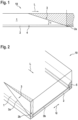
- Figure 1 shows an example of an end of a layer system 10 comprising a first layer 1 made of a first material, e.g., carbon fibers, and a second layer 2 made of a second material, e.g., glass fibers, in a side view.
- the second layer 2 has a lower modulus of elasticity in a longitudinal direction L than the first layer 1.
- the second layer is significantly thinner, in particular, substantially by a factor of 10, than the first layer.
- the layer system 10 has a beveled end with an end surface 3 which is inclined by a bevel angle ⁇ with respect to a contact surface 4 between the first and second layers 1, 2.
- the end surface 4 extends over the entire thickness of the first layer 1 and at least part of the second layer 2, so that the first layer 1 tapers to a point at the bevel angle ⁇ in the side view shown, while the second layer 2 has a blunt end, i.e. an end with an end face 2a oriented perpendicular to the contact surface 4.
- the second layer 2 protrudes beyond the first layer 1.
- the thickness of the layer system 10 is smaller than the thickness of the second layer 2 outside the beveled region, in particular substantially half as large.
- Such a geometry of the end of the layer system 10 can be achieved, for example, by removing a part of the first and second material by at least one separation process.
- the removed material or material to be removed is Figure 1 marked by hatching.
- the layer system 10 can be arranged perpendicular to the contact surface 4, e.g. along the Figure 1 drawn dashed line, so that the end of the layer system 10 is formed.
- the end surface 3 can then be produced, for example, by milling.
- the end surface 3 could of course also be produced by milling at an existing end of the layer system 10 and the resulting tip of the second layer 2 could then be sawn off.
- Figure 2 shows a second example of an end of a layer system 10 comprising a first layer 1 made of a first material and a second layer 2 made of a second material in a three-dimensional representation.
- the end of the layer system 10 is bevelled in such a way that it has an end surface 3 which is opposite a contact surface between the first and second layers 1, 2 (see Figure 1 ) is inclined. This forms a wedge-shaped end of the first layer 1.
- the boundary of the end surface 3 is in Figure 2 indicated by lines 3a and 3b.
- the layer system 10 is preferably produced by means of a pultrusion process, so that the first layer 1 consists of carbon fibers arranged along a longitudinal direction L.
- the second layer e.g. a glass fiber fabric or a carbon fiber fabric or woven fabric, in particular with fibers arranged at an angle to the longitudinal direction L, can be incorporated.
- the second material e.g. a glass fiber fabric or a carbon fiber fabric or woven fabric, in particular with fibers arranged at an angle to the longitudinal direction L.
- the layer system 10 can also be bevelled laterally, e.g. by cutting off a wedge-shaped part at the lateral edge of the layer system 10. This allows the second layer 2 to extend continuously from one side of the layer system 10 to the opposite side in the transverse direction Q in the region of the end of the layer system 10. This case is in Figure 2 on the left side of the layer system 10 facing the viewer.
- a side end surface 2b is created, so that the elastic properties of the layer system 10 are maintained at least in the area in which the second layer 2 projects beyond the first layer 1 (see Figure 1 ), are essentially determined by the elastic properties of the second layer 2 in this area.
- the second layer 2 extends continuously from one side of the layer system 10 to the opposite side along the transverse direction Q, for example by inserting the second material in the form of a fiber bundle (so-called roving) at the lateral ends during the pultrusion of the first material.
- roving a fiber bundle
- Figure 2 shown on the right side of the layer system 10 facing away from the viewer.
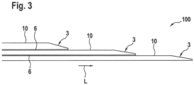
- Figure 3 shows a side view of a rotor blade belt 100 formed from three layer systems 10 stacked one above the other.
- the layer systems 10 are arranged such that a second layer of a layer system 10 made of a second material faces a first layer of an adjacent layer system 10 made of a first material.
- the layer systems 10 are bonded to one another via adhesive layers 6 located between the layer systems 10.
- the layer systems 10 have bevelled ends which are arranged in a staggered manner along a longitudinal direction L of the layer systems 10. This results in a pyramid-shaped structure of the rotor blade belt 100.
- the bevelling of the ends can result in End surfaces 3 are aligned in such a way that the layer systems 10 form flattened steps towards the end of the rotor blade belt 100.
Landscapes
- Engineering & Computer Science (AREA)
- Mechanical Engineering (AREA)
- Life Sciences & Earth Sciences (AREA)
- Sustainable Development (AREA)
- Sustainable Energy (AREA)
- Chemical & Material Sciences (AREA)
- Combustion & Propulsion (AREA)
- General Engineering & Computer Science (AREA)
- Wind Motors (AREA)
Description
- Die Erfindung betrifft ein Verfahren zum Herstellen einer Rotorblattkomponente, insbesondere eines Rotorblattgurts, für ein Rotorblatt einer Windenergieanlage, eine Rotorblattkomponente sowie eine Windenergieanlage mit einer solchen Rotorblattkomponente.
- Rotorblätter für Windenergieanlagen werden häufig aus zwei separat voneinander hergestellten Rotorblattschalen zusammengesetzt. Dabei können im Inneren des Rotorblattes ein oder mehrere Gurte vorgesehen sein, welche im Wesentlichen entlang einer Längsachse des Rotorblatts von der Rotorblattwurzel zur Rotorblattspitze verlaufen und zusätzlich Stabilität verleihen bzw. die elastischen Eigenschaften des Rotorblatts beeinflussen.
- Solche Gurte werden im Allgemeinen unter Verwendung von Strangziehverfahren (Pultrusionsverfahren) hergestellt, wobei z.B. einzelne pultrudierte Lagen aus einem Fasermaterial, z.B. Kohlefaser, zum Gurt geschichtet und miteinander verbunden werden. Um das Risiko eines Ablösens des Endes einer Lage von der darunter liegenden Lage zu verringern, ist es bekannt, die Enden der Lagen z.B. durch Fräsen, Schleifen oder Sägen abzuschrägen und so die Dicke am Ende der Lage zu verringern und somit einen kontinuierlichen Kraftfluss zwischen der endenden Lage und der darunterliegenden Lage zu gewährleisten. Aus technischen Gründen ist es hierbei allerdings nur schwer möglich, die Dicke am Ende der Lage beim Abschrägen auf Null zu reduzieren. Somit bleibt eine Restdicke bestehen, weshalb im Allgemeinen auch ein Restrisiko eines Ablösens verbleibt.
-
EP2778393 A2 offenbart ein Windturbinenblatt, das aus einer ersten und einer zweiten Halbschale gebildet wird, wobei jede Halbschale u.a. eine Holmkappe aufweist, die eine Vielzahl von gestapelten, pultrudierten Lagen umfasst, die in einer Sehnenrichtung flach sind und deren Enden sich verjüngen, um Spannungskonzentrationen in jeder einzelnen Lage zu verringern. -
EP3026259 A1 offenbart Verfahren zur Herstellung von Holmkappen für ein Rotorblatt einer Windenergieanlage. Das Verfahren umfasst die Bereitstellung einer Vielzahl von Pultrusionsprofilen, die aus einer oder mehreren Fasern oder Faserbündeln bestehen, die durch ein Harzmaterial ausgehärtet sind. Ein weiterer Schritt besteht darin, die Enden der Pultrusionsprofile in einem vorbestimmten Winkel zu verjüngen. Das Verfahren umfasst auch das Anordnen der sich verjüngenden Pultrusionen in einer Form der Holmkappe. Das Verfahren pe zu bilden. -
CN103817955 A offenbart ein Herstellungsverfahren für eine Holmkappe aus Verbundwerkstoff für Windturbinenblätter. Für die Hauptholmkappen, die für 50 m lange Windturbinenblätter verwendet werden, wird die Anzahl der Lagen in der Regel entsprechend dem Produktspezifikationsplan für die Windturbinenblätter festgelegt, z.B. 65 Faserschichten. Die Faserlänge der Lagen wird entsprechend der Länge des Windturbinenblattes in Übereinstimmung mit den Konstruktionsanforderungen an die Hauptholmkappe festgelegt, wobei die Faserlänge jeder Lage im Allgemeinen unterschiedlich ist. Es ist eine Aufgabe der Erfindung, eine verbesserte Rotorblattkomponente bereitzustellen, insbesondere die Belastbarkeit einer Rotorblattkomponente zu erhöhen. - Diese Aufgabe wird durch ein Verfahren zur Herstellung einer Rotorblattkomponente nach Anspruch 1, eine Rotorblattkomponente nach Anspruch 9, sowie eine Windenergieanlage gemäß den unabhängigen Ansprüchen gelöst.
- Gemäß einem ersten Aspekt der Erfindung wird bei einem Verfahren zum Herstellen einer Rotorblattkomponente, insbesondere eines Rotorblattgurts, für ein Rotorblatt einer Windenergieanlage ein Schichtsystem aus einer ersten Schicht aus einem ersten Material und einer zweiten Schicht aus einem zweiten Material hergestellt. Dabei weist das zweite Material einen kleineren Elastizitätsmodul auf als das erste Material, und die zweite Schicht erstreckt sich zumindest abschnittsweise entlang der ersten Schicht. Das Schichtsystem wird an mindestens einem Ende mithilfe wenigstens eines Trennverfahrens in der Weise abgeschrägt, dass die zweite Schicht an dem mindestens einen Ende des Schichtsystems über die erste Schicht hinausragt. Zudem wird das Schichtsystem mit wenigstens einem weiteren solchen Schichtsystem zur Rotorblattkomponente verbunden.
- Gemäß einem zweiten Aspekt der Erfindung weist eine, vorzugsweise mit dem Verfahren nach dem ersten Aspekt der Erfindung hergestellte, Rotorblattkomponente, insbesondere Rotorblattgurt, für ein Rotorblatt einer Windenergieanlage wenigstens ein Schichtsystem aus einer ersten Schicht aus einem ersten Material und einer zweiten Schicht aus einem zweiten Material auf. Die zweite Schicht ist dabei zumindest abschnittsweise auf der ersten Schicht aufgebracht und das zweite Material weist einen kleineren Elastizitätsmodul auf als das erste Material. Zudem ist das Schichtsystem an mindestens einem Ende in der Weise abgeschrägt, dass die zweite Schicht an dem mindestens einen Ende des Schichtsystems über die erste Schicht hinausragt. Die Rotorblattkomponente weist des Weiteren wenigstens ein weiteres solches Schichtsystem auf, mit welchem das wenigstens eine Schichtsystem zur Rotorblattkomponente verbunden ist.
- Gemäß einem dritten Aspekt der Erfindung weist eine Windenergieanlage mindestens ein Rotorblatt auf, welches eine mit dem Verfahren nach dem ersten Aspekt der Erfindung hergestellte Rotorblattkomponente und/oder eine Rotorblattkomponente nach dem zweiten Aspekt der Erfindung aufweist.
- Vorzugsweise werden bzw. sind solche Schichtsysteme derart miteinander verbunden, dass die zweite Schicht eines ersten Schichtsystems im Bereich ihres mindestens einen abgeschrägten Endes, insbesondere vollständig, auf der ersten Schicht eines zweiten Schichtsystems aufliegt und/oder die zweite Schicht eines ersten Schichtsystems im Bereich ihres mindestens einen abgeschrägten Endes der ersten Schicht eines zweiten Schichtsystems zugewandt ist. Die zweite Schicht des ersten Schichtsystems kann hierbei direkt auf der ersten Schicht des zweiten Schichtsystems aufliegen. Alternativ kann aber auch mindestens eine weitere Schicht, etwa eine Kleberschicht und/oder eine Schicht aus dünnem Vlies bzw. aus mit Harz getränktem Fasermaterial, zwischen der zweiten Schicht des ersten Schichtsystems und der ersten Schicht des zweiten Schichtsystems liegen.
- Bevorzugte Aspekte der Erfindung basieren auf dem Ansatz, eine Rotorblattkomponente wie beispielsweise einen Rotorblattgurt aus mehreren Schichtsystemen herzustellen, wobei vorzugsweise jedes Schichtsystem die Form eines Schichtverbunds hat und eine erste Schicht aus einem ersten Material sowie eine zweite Schicht aus einem zweiten Material aufweist. Dabei weist das zweite Material einen kleineren Elastizitätsmodul auf das erste Material, so dass die Steifigkeit der zweiten Schicht geringer ist als die Steifigkeit der ersten Schicht, selbst wenn die beiden Schichten die gleiche Dicke aufweisen.
- Die Schichtsysteme können jeweils an mindestens einem Ende abgeschrägt werden, so dass an dem mindestens einen Ende die zweite Schicht jeweils über die erste Schicht hinausragt. Durch Abschrägen des Schichtsystems am mindestens einen Ende, was auch als Schäften des Schichtsystems bezeichnet werden kann, wird eine Endfläche des Schichtsystems, insbesondere der ersten Schicht, erzeugt. Die Endfläche ist dabei gegenüber einer Kontaktfläche zwischen der ersten und zweiten Schicht geneigt, insbesondere so dass die erste Schicht keilförmig endet bzw. die Dicke am Ende der ersten Schicht gegen Null geht. Beim Zusammenfügen mehrerer solcher Schichtsysteme ergibt sich somit in bevorzugter Weise ein pyramidenartiger Stapel mit hoher Tragfähigkeit, da Steifigkeitssprünge an den Enden der ersten Schichten vermieden werden können und das Risiko eines Ablösens verringert wird. Vorzugsweise werden die Schichtsysteme in der Weise miteinander verbunden, dass die zweiten Schichten den ersten Schichten des jeweils darunter liegenden Schichtsystems zugewandt sind.
- Da die Steifigkeit des Schichtsystems im Bereich der zweiten Schicht reduziert ist, können Steifigkeitssprünge zwischen den einzelnen Schichtsystemen bzw. in der Rotorblattkomponente und somit das Risiko eines Ablösens der einzelnen Schichtsysteme voneinander verringert werden. Gleichzeitig hat die kleinere Steifigkeit der zweiten Schicht auch Auswirkungen auf den möglichen Abschrägwinkel, unter dem ein Teil des Schichtsystems, insbesondere der ersten Schicht, z.B. durch Fräsen, Schneiden, Schleifen oder Sägen abgetrennt wird. Z.B. kann der Abschrägwinkel durch die zweite Schicht mit geringerer Steifigkeit größer als bei konventionellen Lagen von Rotorblattkomponenten gewählt und somit die Kosten für die Herstellung der Schäftungen reduziert werden. Außerdem können die Enden der einzelnen Schichtsysteme näher beieinander liegen. Es ist etwa denkbar, das mindestens eine Ende des Schichtsystemes derart abzuschrägen, dass das mindestens eine Ende eine mit dem Abschrägwinkel korrespondierende Steigung zwischen 1:50 und 1:200, insbesondere im Wesentlichen 1:80, relativ zur Kontaktfläche zwischen erster und zweiter Schicht aufweist.
- Ein Schichtsystem kann beispielsweise aus stranggezogenen bzw. pultrudierten Kohlefasern, welche die erste Schicht bilden, und einem Glasfasergelege, welches die zweite Schicht bildet, gebildet werden. Beim Abschrägen des wenigstens einen Endes des Schichtsystems wird dann in bevorzugter Weise zumindest eine Kante der Kohlefaserschicht abgetrennt, so dass sich die Kohlefaserschicht zum Ende hin verjüngt, insbesondere unter dem Abschrägwinkel spitz bzw. keilförmig zuläuft. Gegebenenfalls kann beim Abschrägen auch zumindest eine Kante des Glasfasergeleges abgetrennt werden, so dass sich auch das Glasfasergelege zum Ende hin verjüngt, wodurch die Steifigkeit der zweiten Schicht zum Ende hin weiter reduziert werden kann.
- Insgesamt wird durch die Erfindung das Herstellen von Rotorblättern verbessert und eine entsprechende Windenergieanlage angegeben.
- In einer bevorzugten Ausführungsform wird das Schichtsystem hergestellt, indem die zweite Schicht aus dem zweiten Material beim Fertigen der ersten Schicht aus dem ersten Material mit der ersten Schicht verbunden wird. Beispielsweise kann die erste Schicht auf der zweiten Schicht oder zumindest abschnittsweise um die zweite Schicht herum gefertigt werden. Es ist etwa denkbar, dass das erste Material in einem Strangziehverfahren pultrudiert und dabei vorzugsweise auf der zweiten Schicht und/oder um die zweite Schicht herum abgelegt wird. Dadurch kann das Schichtsystem in besonders wenigen Arbeitsschritten hergestellt werden. Insbesondere kann somit auch eine besonders feste Verbindung zwischen der ersten und zweiten Schicht hergestellt werden.
- Insbesondere kann die zweite Schicht beim Fertigen der ersten Schicht aus dem ersten Material in die erste Schicht bzw. in eine Teilschicht des ersten Materials eingearbeitet werden. Es ist beispielsweise vorteilhaft, wenn das zweite Material, z.B. als Glasfasergelege oder Glasfaserbündel (sog. Rovinge), bei der Herstellung der ersten Schicht bereits als zweite Schicht eingebracht wird. Dadurch können sich die Faserbündel sowie Fasergelege mit der ersten Schicht zuverlässig verbinden, wobei die Kontaktfläche zwischen den Faserbündeln oder -gelegen und der ersten Schicht uneben sein kann. Insbesondere kann sich somit beim Abschrägen des mindestens einen Endes ein unregelmäßiger, vorzugsweise kontinuierlicher Übergang zwischen der ersten und zweiten Schicht ergeben. Dies ist besonders bevorzugt, da somit die Bildung einer Rissfront und somit das Ablösen bei hohen Längsbelastungen verzögert werden kann.
- Das Einbringen von Faserbündeln hat, insbesondere gegenüber Gelegen, den Vorteil, dass die Faserbündel auch an den seitlichen, entlang der Längsrichtung verlaufenden Rändern der ersten Schicht eingebracht werden können. In besonders bevorzugter Weise werden beim Herstellen der ersten Schicht Faserbündel (Rovinge) in der Weise eingebracht, dass zumindest ein Teil der ersten Schicht seitlich von den Faserbündeln eingefasst ist. Gegebenenfalls können die eingebrachten Faserbündel auch ein Fasergelege mit einfassen. Dadurch kann sichergestellt werden, dass die elastischen Eigenschaften des Schichtsystems im Bereich des wenigstens einen abgeschrägten Endes im Wesentlichen durch die zweite Schicht bestimmt werden.
- In einer weiteren bevorzugten Ausführungsform werden die erste Schicht aus dem ersten Material und die zweite Schicht aus dem zweiten Material separat gefertigt, wobei das Schichtsystem durch Aufbringen der zweiten Schicht auf die erste Schicht hergestellt wird. Dadurch kann auf besonders einfache Weise sichergestellt werden, dass sich die zweite Schicht, zumindest im Bereich des wenigstens einen abgeschrägten Endes, vollständig entlang der ersten Schicht erstreckt, insbesondere auch an bzw. bis zu deren seitlichen Rändern, d.h. senkrecht zur Längsrichtung über die gesamte Breite der ersten Schicht.
- In einer weiteren bevorzugten Ausführungsform wird die zweite Schicht nur in einem Bereich des mindestens einen Endes der ersten Schicht, in welchem das Schichtsystem abgeschrägt wird, verbunden oder aufgebracht. Dadurch kann Material und Gewicht des Schichtsystems bzw. der Rotorblattkomponente eingespart werden. Zudem ist es dadurch möglich, die elastischen Eigenschaften der Rotorblattkomponente in Längsrichtung abschnittsweise zu variieren.
- In einer weiteren bevorzugten Ausführungsform wird das Schichtsystem an dem mindestens einen Ende mithilfe des wenigstens einen Trennverfahrens in der Weise abgeschrägt, dass das Ende der über die erste Schicht hinausragenden zweiten Schicht im Wesentlichen eine rechteckige, insbesondere senkrecht zur Längsrichtung verlaufende, Stirnfläche und/oder eine endliche Schichtdicke aufweist. Die Höhe der Seitenfläche bzw. die Dicke der zweiten Schicht ist dabei in bevorzugter Weise wenigstens halb so groß wie die durchschnittliche Dicke der zweiten Schicht, insbesondere wenigstens halb so groß wie die Dicke der zweiten Schicht außerhalb des Bereichs des wenigstens einen abgeschrägten Endes. Das Schichtsystem kann beispielsweise derart abgeschrägt werden, dass die Seitenfläche eine Höhe bzw. die zweite Schicht am abgeschrägten Ende eine Dicke von im Wesentlichen 0,5 mm aufweist. Dadurch kann vermieden werden, dass die Steifigkeit der zweiten Schicht im Bereich, in dem sie über die erste Schicht hinausragt, so gering ist, dass sie beispielsweise bei dem wenigstens einen Trennverfahren und/oder beim Verbinden mehrerer Schichtsysteme beschädigt wird.
- In einer weiteren bevorzugten Ausführungsform wird das mindestens eine abgeschrägte Ende des Schichtsystems mit einer dritten Schicht aus einem dritten Material abgedeckt. Vorzugsweise weist das dritte Material einen Elastizitätsmodul, insbesondere in Längsrichtung, auf, der größer ist als der Elastizitätsmodul der zweiten und/oder ersten Schicht. Alternativ kann das dritte Material aber auch gleich dem ersten oder dem zweiten Material sein. Durch die Abdeckung des mindestens einen abgeschrägten Endes durch die dritte Schicht wird die Schälbelastung auf das mindestens eine Ende reduziert sowie ein weiterer Lastpfad für den Kraftfluss aus dem endenden Schichtsystem bereitgestellt.
- In einer weiteren bevorzugten Ausführungsform wird das Schichtsystem in der Weise abgeschrägt, dass das Schichtsystem im Bereich des mindestens einen abgeschrägten Endes eine Endfläche, die gegenüber einer Kontaktfläche zwischen der ersten und zweiten Schicht geneigt ist, und zwei einander gegenüberliegende, insbesondere durch die Endfläche verbundenen, Seitenendflächen aufweist, die im Wesentlichen senkrecht zur Kontaktfläche zwischen der ersten und zweiten Schicht verlaufen und derart gegeneinander geneigt sind, dass sie zum Ende des Schichtsystems aufeinander zulaufen. Mit anderen Worten kann das Schichtsystem derart abgeschrägt werden, dass es im Bereich des abgeschrägten Endes spitz zuläuft bzw. einen halbierten Pyramidenstumpf bildet, wobei die die beiden einander gegenüberliegenden Seitenendflächen zusammen mit der Endfläche zumindest einen Teil der Mantelfläche des Pyramidenstumpfes bilden. Dadurch kann sichergestellt werden, dass die elastischen Eigenschaften des Schichtsystems im Bereich des zumindest einen abgeschrägten Endes von der zweiten Schicht bestimmt werden, auch wenn sich die zweite Schicht außerhalb des Bereichs des abgeschrägten Endes nicht an bzw. bis zu den seitlichen Rändern der ersten Schicht, d.h. nicht über die gesamte Breite der ersten Schicht, erstreckt.
- In einer weiteren bevorzugten Ausführungsform weist die zweite Schicht eine geringere Dicke auf als die erste Schicht. Dadurch wird ermöglicht, dass die Tragfähigkeit des Schichtsystems im Wesentlichen durch die erste Schicht bestimmt wird. Insbesondere kann so erreicht werden, dass die Tragkraft der Rotorblattkomponente im Wesentlichen vergleichbar mit der Tragkraft konventioneller Rotorblattkomponenten ist.
- In einer weiteren bevorzugten Ausführungsform weist die erste Schicht eine Dicke zwischen 1 mm und 10 mm, vorzugsweise zwischen 2 mm und 5 mm, auf. Alternativ oder zusätzlich weist die zweite Schicht eine Dicke zwischen 0.1 mm und 1 mm, vorzugsweise zwischen 0.2 mm und 0.5 mm, auf. Dadurch kann eine ausreichende Tragfähigkeit des Schichtsystems bzw. der Rotorblattkomponente bei gleichzeitig reduziertem Risiko einer Ablösung der Schichten voneinander sichergestellt werden. Insbesondere ist auf diese Weise ein optimales Verhältnis zwischen den Schichtdicke der ersten und zweiten Schicht erreichbar, bei dem die höchste Tragfähigkeit bei reduziertem Ablösungsrisiko vorliegt.
- In einer weiteren bevorzugten Ausführungsform weist das erste Material einen Elastizitätsmodul in Längsrichtung zwischen 5·104 N/mm2 und 50·104 N/mm2, vorzugsweise zwischen 10·104 N/mm2 und 30·104 N/mm2, auf. Alternativ oder zusätzlich weist das zweite Material einen Elastizitätsmodul in Längsrichtung zwischen 1·104 N/mm2 und 6·104 N/mm2, vorzugsweise zwischen 4·104 N/mm2 und 5·104 N/mm2, auf. Das erste Material bzw. die erste Schicht kann beispielsweise Kohlenstofffasern aufweisen und insbesondere als Gewebe oder Gelege ausgebildet sein. Das zweite Material bzw. die zweite Schicht kann beispielsweise Glasfasern aufweisen und insbesondere als Gewebe oder Gelege ausgebildet sein. Es ist auch denkbar, dass das erste und/oder zweite Material Faserbündel (sog. Rovinge) aufweist und die erste bzw. zweite Schicht wenigstens ein solches Faserbündel enthält, insbesondere aus einem oder mehreren solcher Faserbündel gebildet wird.
- In einer weiteren bevorzugten Ausführungsform weisen das erste Material und das zweite Material Fasern auf, wobei der Anteil an Fasern, die im Wesentlichen entlang der Längsrichtung verlaufen, im zweiten Material geringer ist als im ersten Material. Dabei kann das erste Material dem zweiten Material ansonsten entsprechen, d.h. das erste Material kann gleich dem zweiten Material sein. Das erste Material bzw. die erste Schicht kann beispielsweise Kohlefasergewebe aufweisen, in dem sich die Kohlenstofffasern im Wesentlichen entlang der Längsrichtung erstrecken. Das zweite Material bzw. die zweite Schicht kann ebenfalls ein Kohlefasergewebe aufweisen, indem sich die Kohlenstofffasern jedoch unter einem Winkel zur Längsrichtung, z.B. unter 45° oder sogar unter 90° bzw. senkrecht, zur Längsrichtung, erstrecken. Dadurch ist eine zuverlässige Reduktion des Elastizitätsmoduls in Längsrichtung beim Übergang von der ersten Schicht in die zweite Schicht erreichbar.
- Weitere Vorteile, Merkmale und Anwendungsmöglichkeiten der vorliegenden Erfindung ergeben sich aus der nachfolgenden Beschreibung in Zusammenhang mit den Figuren. Es zeigen:
- Fig. 1
- ein Beispiel eines Endes eines Schichtsystems aus einer ersten Schicht und einer zweiten Schicht in einer Seitenansicht;
- Fig. 2
- ein Beispiel eines Endes eines Schichtsystems aus einer ersten Schicht und einer zweiten Schicht in einer dreidimensionalen Darstellung; und
- Fig. 3
- ein Beispiel eines Endes eines Rotorblattgurts in einer Seitenansicht.
-
Figur 1 zeigt ein Beispiel eines Endes eines Schichtsystems 10 aus einer ersten Schicht 1 aus einem ersten Material, z.B. Kohlenstofffasern, und einer zweiten Schicht 2 aus einem zweiten Material, z.B. Glasfasern, in einer Seitenansicht. Die zweite Schicht 2 weist dabei in einer Längsrichtung L einen geringeren Elastizitätsmodul auf als die erste Schicht 1. Zudem ist die zweite Schicht wesentlich dünner, insbesondere im Wesentlichen um den Faktor 10, ausgebildet als die erste Schicht. - Das Schichtsystem 10 weist erfindungsgemäß ein abgeschrägtes Ende mit einer Endfläche 3 auf, die gegenüber einer Kontaktfläche 4 zwischen der ersten und zweiten Schicht 1, 2 um einen Abschrägwinkel α geneigt ist. Die Endfläche 4 erstreckt sich dabei über die gesamte Dicke der ersten Schicht 1 und zumindest einen Teil der zweiten Schicht 2, so dass die erste Schicht 1 unter dem Abschrägwinkel α in der gezeigten Seitenansicht spitz zuläuft, während die zweite Schicht 2 ein stumpfes Ende, d.h. ein Ende mit einer senkrecht zur Kontaktfläche 4 orientierten Stirnfläche 2a, aufweist. Dabei ragt die zweiten Schicht 2 über die erste Schicht 1 hinaus.
- Am äußersten Ende ist die Dicke des Schichtsystems 10 kleiner als die Dicke der zweiten Schicht 2 außerhalb des abgeschrägten Bereichs, insbesondere im Wesentlichen halb so groß.
- Eine solche Geometrie des Endes des Schichtsystems 10 kann z.B. erreicht werden, indem ein Teil des ersten und zweiten Materials durch wenigstens ein Trennverfahren entfernt wird. Das entfernte bzw. zu entfernende Material ist in der vorliegenden
Figur 1 durch die Schraffur gekennzeichnet. - Beispielsweise kann das Schichtsystem 10 senkrecht zur Kontaktfläche 4, z.B. entlang der in
Figur 1 eingezeichneten gestrichelten Linie, durchgesägt werden, so dass das Ende des Schichtsystems 10 gebildet wird. Anschließend kann die Endfläche 3 etwa durch Fräsen hergestellt werden. Alternativ könnte in dazu umgekehrter Reihenfolge natürlich auch an einem bereits bestehenden Ende des Schichtsystems 10 die Endfläche 3 durch Fräsen hergestellt werden und anschließend die dabei entstandene Spitze der zweiten Schicht 2 abgesägt werden. -
Figur 2 zeigt ein zweites Beispiel eines Endes eines Schichtsystems 10 aus einer ersten Schicht 1 aus einem ersten Material und einer zweiten Schicht 2 aus einem zweiten Material in einer dreidimensionalen Darstellung. Das Ende des Schichtsystems 10 ist dabei in der Weise abgeschrägt, dass es eine Endfläche 3 aufweist, die gegenüber einer Kontaktfläche zwischen der ersten und zweiten Schicht 1, 2 (sieheFigur 1 ) geneigt ist. Dadurch wird ein keilförmig zulaufendes Ende der ersten Schicht 1 gebildet. Die Begrenzung der Endfläche 3 ist inFigur 2 durch die Linien 3a und 3b angedeutet. - Das Schichtsystem 10 wird vorzugsweise mittels eines Strangziehverfahrens hergestellt, so dass die erste Schicht 1 aus entlang einer Längsrichtung L angeordneten Kohlefasern besteht. Im Rahmen des Strangziehverfahrens kann die zweite Schicht 2, z.B. einem Glasfasergelege oder einem Kohlefasergelege oder -gewebe, insbesondere mit unter einem Winkel zur Längsrichtung L angeordneten Fasern, eingearbeitet werden. Insbesondere ist es denkbar, das zweite Material beim Pultrudieren des ersten Materials mit einzuführen, so dass die zweite Schicht 2 von der ersten Schicht 1 seitlich, d.h. in einer Querrichtung Q quer zur Längsrichtung L, eingefasst ist.
- Um sicherzustellen, dass diese Einfassungen die elastischen Eigenschaften des Schichtsystems 10 im Bereich des Endes, in dem das Schichtsystem 10 abgeschrägt ist, nicht beeinflussen, kann das Schichtsystem 10 auch seitlich abgeschrägt werden, z.B. indem ein keilförmiger Teil am seitlichen Rand des Schichtsystems 10 abgetrennt wird. Dadurch kann sich die zweite Schicht 2 im Bereich des Endes des Schichtsystems 10 durchgängig von einer Seite des Schichtsystems 10 zur gegenüberliegenden Seite in der Querrichtung Q erstrecken. Dieser Fall ist in
Figur 2 auf der dem Betrachter zugewandten linken Seite des Schichtsystems 10 gezeigt. Bei der seitlichen Abschrägung wird dabei eine Seitenendfläche 2b erzeugt, so dass die elastischen Eigenschaften des Schichtsystems 10 zumindest im Bereich, in dem die zweite Schicht 2 über die erste Schicht 1 hinausragt (sieheFigur 1 ), im Wesentlichen durch die elastischen Eigenschaften der zweiten Schicht 2 in diesem Bereich bestimmt sind. - Alternativ ist es auch möglich, bereits beim Strangziehen des Schichtsystems 10 sicherzustellen, dass sich die zweite Schicht 2 durchgehend von einer Seite des Schichtsystems 10 bis zur gegenüberliegenden Seite entlang der Querrichtung Q erstreckt, etwa indem beim Strangziehen des ersten Materials an den seitlichen Enden das zweite Material in Form eines Faserbündels (sog. Roving) eingelegt wird. Dadurch entstehen längliche, insbesondere streifenförmige, Bereiche 5 von geringer Steifigkeit, welche sich seitlich der zweiten Schicht 2 entlang der Längsrichtung L erstrecken und die zweite Schicht 2 seitlich einfassen. Dieser Fall ist in
Figur 2 auf der dem Betrachter abgewandten rechten Seite der Schichtsystems 10 gezeigt. -
Figur 3 zeigt einen Rotorblattgurt 100, der aus drei übereinander geschichteten und Schichtsystemen 10 gebildet ist, in einer Seitenansicht. Die Schichtsysteme 10 sind dabei in der Weise angeordnet, dass eine zweite Schicht eines Schichtsystems 10 aus einem zweiten Material jeweils einer ersten Schicht eines benachbarten Schichtsystems 10 aus einem ersten Material zugewandt ist. Die Schichtsysteme 10 sind über zwischen den Schichtsystemen 10 liegende Klebeschichten 6 miteinander verklebt. - Die Schichtsysteme 10 weisen abgeschrägte Enden auf, die entlang einer Längsrichtung L der Schichtsysteme 10 gestaffelt angeordnet sind. Dadurch ergibt sich ein pyramidenförmiger Aufbau des Rotorblattgurts 100. Dabei können durch das Abschrägen der Enden entstandene Endflächen 3 in der Weise ausgerichtet sein, dass die Schichtsysteme 10 zum Ende des Rotorblattgurts 100 abgeflachte Stufen bilden.
Claims (14)
- Verfahren zum Herstellen einer Rotorblattkomponente, insbesondere eines Rotorblattgurts (100), für ein Rotorblatt einer Windenergieanlage, wobei- ein Schichtsystem (10) aus einer ersten Schicht (1) aus einem ersten Material und einer zweiten Schicht (2) aus einem zweiten Material hergestellt wird, wobei sich die zweite Schicht (2) zumindest abschnittsweise entlang einer Längsrichtung (L) der ersten Schicht (1) erstreckt und das zweite Material ein kleineres Elastizitätsmodul in Längsrichtung (L) aufweist als das erste Material,- das Schichtsystem (10) an mindestens einem Ende mithilfe wenigstens eines Trennverfahrens in der Weise abgeschrägt wird, dass die zweite Schicht (2) an dem mindestens einen Ende des Schichtsystems (10) über die erste Schicht (1) hinausragt, und- das Schichtsystem (10) mit wenigstens einem anderen Schichtsystem (10) zur Rotorblattkomponente verbunden wird,dadurch gekennzeichnet, dass
das Schichtsystem (10) an dem mindestens einen Ende mithilfe des wenigstens einen Trennverfahrens in der Weise abgeschrägt wird, dass ein Teil des ersten und zweiten Materials entfernt wird, so dass das Schichtsystem (10) ein abgeschrägtes Ende mit einer Endfläche (3) aufweist, die gegenüber einer Kontaktfläche (4) zwischen der ersten und zweiten Schicht (1, 2) um einen Abschrägwinkel (α) geneigt ist und sich über die gesamte Dicke der ersten Schicht (1) und zumindest einen Teil der zweiten Schicht (2) erstreckt, so dass die erste Schicht (1) unter dem Abschrägwinkel (α) spitz zuläuft, während die über die erste Schicht (1) hinausragende zweite Schicht (2) ein stumpfes Ende mit einer senkrecht zur Kontaktfläche (4) orientierten Stirnfläche (2a) aufweist. - Verfahren nach Anspruch 1, wobei das Schichtsystem (10) hergestellt wird, indem das zweite Material beim Fertigen der ersten Schicht (1) aus dem ersten Material in eine Teilschicht des ersten Materials mit eingearbeitet wird und dabei die zweite Schicht (2) bildet.
- Verfahren nach Anspruch 1, wobei die erste Schicht (1) aus dem ersten Material und die zweite Schicht (2) aus dem zweiten Material separat gefertigt werden und das Schichtsystem (10) durch Aufbringen der zweiten Schicht (2) auf die erste Schicht (1) hergestellt wird.
- Verfahren nach einem der Ansprüche 2 oder 3, wobei die zweite Schicht (2) nur in einem Bereich des mindestens einen Endes der ersten Schicht (1), in welchem das Schichtsystem (10) abgeschrägt wird, eingearbeitet bzw. aufgebracht wird.
- Verfahren nach einem der vorangehenden Ansprüche, wobei die Stirnfläche (2a) rechteckig ist.
- Verfahren nach einem der vorangehenden Ansprüche, wobei die Höhe der Stirnfläche (2a) wenigstens halb so groß ist wie die Dicke der zweiten Schicht (2) außerhalb des Bereichs des wenigstens einen abgeschrägten Endes.
- Verfahren nach einem der vorangehenden Ansprüche, wobei das mindestens eine abgeschrägte Ende des Schichtsystems (10) mit einer dritten Schicht aus einem dritten Material abgedeckt wird.
- Verfahren nach einem der vorangehenden Ansprüche, wobei das Schichtsystem (10) in der Weise abgeschrägt wird, dass das Schichtsystem (10) im Bereich des mindestens einen abgeschrägten Endes eine Endfläche (3), die gegenüber einer Kontaktfläche (4) zwischen der ersten und zweiten Schicht (1, 2) geneigt ist, und zwei einander gegenüberliegende Seitenendflächen (2b) aufweist, die im Wesentlichen senkrecht zur Kontaktfläche (4) zwischen der ersten und zweiten Schicht (1, 2) verlaufen und derart gegeneinander geneigt sind, dass sie zum Ende des Schichtsystems (10) aufeinander zulaufen.
- Rotorblattkomponente, insbesondere Rotorblattgurt (100), für ein Rotorblatt einer Windenergieanlage, mit- wenigstens einem Schichtsystem (10) aus einer ersten Schicht (1) aus einem ersten Material und einer zweiten Schicht (2) aus einem zweiten Material, wobei die zweite Schicht (2) zumindest abschnittsweise entlang einer Längsrichtung (L) auf der ersten Schicht (1) aufgebracht ist und das zweite Material einen kleineren Elastizitätsmodul in Längsrichtung (L) aufweist als das erste Material und das Schichtsystem (10) an mindestens einem Ende in der Weise abgeschrägt ist, dass die zweite Schicht (2) an dem mindestens einen Ende des Schichtsystems (10) über die erste Schicht (1) hinausragt, und- wenigstens einem anderen Schichtsystem (10), mit welchem das wenigstens eine Schichtsystem (10) zur Rotorblattkomponente verbunden istdadurch gekennzeichnet, dass
das Schichtsystem (10) an dem mindestens einen Ende in der Weise abgeschrägt ist, dass ein Teil des ersten und zweiten Materials entfernt ist, so dass das Schichtsystem (10) ein abgeschrägtes Ende mit einer Endfläche (3) aufweist, die gegenüber einer Kontaktfläche (4) zwischen der ersten und zweiten Schicht (1, 2) um einen Abschrägwinkel (α) geneigt ist und sich über die gesamte Dicke der ersten Schicht (1) und zumindest einen Teil der zweiten Schicht (2) erstreckt, so dass die erste Schicht (1) unter dem Abschrägwinkel (α) spitz zuläuft, während die über die erste Schicht (1) hinausragende zweite Schicht (2) ein stumpfes Ende mit einer senkrecht zur Kontaktfläche (4) orientierten Stirnfläche (2a) aufweist. - Rotorblattkomponente nach Anspruch 9, wobei die zweite Schicht (2) eine geringere Dicke aufweist als die erste Schicht (1).
- Rotorblattkomponente nach einem der Ansprüche 9 oder 10, wobei die erste Schicht (1) eine Dicke zwischen 1 mm und 10 mm, vorzugsweise zwischen 2 mm und 5 mm, aufweist und/oder die zweite Schicht (2) eine Dicke zwischen 0.1 mm und 1 mm, vorzugsweise zwischen 0.2 mm und 0.5 mm, aufweist.
- Rotorblattkomponente nach einem der Ansprüche 9 bis 11, wobei das erste Material einen Elastizitätsmodul in Längsrichtung (L) zwischen 5·104 N/mm2 und 50·104 N/mm2, vorzugsweise zwischen 10·104 N/mm2 und 30·104 N/mm2, aufweist und/oder das zweite Material einen Elastizitätsmodul in Längsrichtung (L) zwischen 1·104 N/mm2 und 6·104 N/mm2, vorzugsweise zwischen 4·104 N/mm2 und 5·104 N/mm2, aufweist.
- Rotorblattkomponente nach einem der Ansprüche 9 bis 12, wobei das erste Material und das zweite Material Fasern aufweisen und der Anteil an Fasern, die im Wesentlichen entlang der Längsrichtung (L) verlaufen, im zweiten Material geringer ist als im ersten Material.
- Windenergieanlage mit mindestens einem Rotorblatt, welches eine mit dem Verfahren nach einem der Ansprüche 1 bis 8 hergestellte Rotorblattkomponente und/oder eine Rotorblattkomponente nach einem der Ansprüche 9 bis 13 aufweist.
Applications Claiming Priority (2)
| Application Number | Priority Date | Filing Date | Title |
|---|---|---|---|
| DE102018009338.8A DE102018009338A1 (de) | 2018-11-28 | 2018-11-28 | Rotorblattkomponente, Verfahren zu deren Herstellung und Windenergieanlage |
| PCT/EP2019/082397 WO2020109218A1 (de) | 2018-11-28 | 2019-11-25 | Rotorblattkomponente, verfahren zu deren herstellung und windenergieanlage |
Publications (2)
| Publication Number | Publication Date |
|---|---|
| EP3887131A1 EP3887131A1 (de) | 2021-10-06 |
| EP3887131B1 true EP3887131B1 (de) | 2025-06-04 |
Family
ID=68696424
Family Applications (1)
| Application Number | Title | Priority Date | Filing Date |
|---|---|---|---|
| EP19809451.8A Active EP3887131B1 (de) | 2018-11-28 | 2019-11-25 | Rotorblattkomponente, verfahren zu deren herstellung und windenergieanlage |
Country Status (7)
| Country | Link |
|---|---|
| US (1) | US12031517B2 (de) |
| EP (1) | EP3887131B1 (de) |
| CN (1) | CN113039059B (de) |
| DE (1) | DE102018009338A1 (de) |
| DK (1) | DK3887131T3 (de) |
| ES (1) | ES3039057T3 (de) |
| WO (1) | WO2020109218A1 (de) |
Citations (1)
| Publication number | Priority date | Publication date | Assignee | Title |
|---|---|---|---|---|
| EP3884157B1 (de) * | 2018-11-20 | 2022-09-28 | Vestas Wind Systems A/S | Äquipotenzialbonden einer windturbinenrotorschaufel |
Family Cites Families (12)
| Publication number | Priority date | Publication date | Assignee | Title |
|---|---|---|---|---|
| US20100143142A1 (en) * | 2008-12-11 | 2010-06-10 | Afroz Akhtar | Sparcap system for wind turbine rotor blade and method of fabricating wind turbine rotor blade |
| DE102009047570A1 (de) | 2009-12-07 | 2011-06-09 | Repower Systems Ag | Gurt eines Rotorblatts einer Windenergieanlage |
| US20110142662A1 (en) | 2010-10-28 | 2011-06-16 | General Electric Company | Spar Cap Assembly for a Wind Turbine Rotor Blade |
| US20140271217A1 (en) * | 2013-03-15 | 2014-09-18 | Modular Wind Energy, Inc. | Efficient wind turbine blade design and associated manufacturing methods using rectangular spars and segmented shear web |
| TR201809364T4 (tr) * | 2013-07-12 | 2018-07-23 | Lm Wind Power Int Tech Ii Aps | Bir rüzgar türbini kanadı üretimine yönelik usul ve aletler. |
| CN103817955A (zh) | 2014-02-28 | 2014-05-28 | 中材科技风电叶片股份有限公司 | 一种风电叶片用复合材料主梁帽的制作方法 |
| US20160146185A1 (en) | 2014-11-25 | 2016-05-26 | General Electric Company | Methods for manufacturing a spar cap for a wind turbine rotor blade |
| DE102016101663A1 (de) * | 2016-01-29 | 2017-08-03 | Wobben Properties Gmbh | Holmgurt und Herstellungsverfahren |
| DE102016009640A1 (de) * | 2016-08-10 | 2018-02-15 | Senvion Gmbh | Gurt aus vorgefertigten Elementen mit Gelege und ein Verfahren zu seiner Fertigung |
| EP3330528B1 (de) * | 2016-12-05 | 2020-07-22 | Nordex Energy GmbH | Gurtbaugruppe für ein windenergieanlagenrotorblatt |
| DK3726049T3 (da) * | 2019-04-15 | 2023-04-03 | Siemens Gamesa Renewable Energy Innovation & Technology SL | Rotorblad og fremgangsmåde til fremstilling af et rotorblad |
| EP3922446B1 (de) * | 2020-06-12 | 2025-01-29 | Siemens Gamesa Renewable Energy A/S | Verfahren zur herstellung einer windturbinenschaufel |
-
2018
- 2018-11-28 DE DE102018009338.8A patent/DE102018009338A1/de active Pending
-
2019
- 2019-11-25 WO PCT/EP2019/082397 patent/WO2020109218A1/de not_active Ceased
- 2019-11-25 ES ES19809451T patent/ES3039057T3/es active Active
- 2019-11-25 CN CN201980076021.2A patent/CN113039059B/zh active Active
- 2019-11-25 EP EP19809451.8A patent/EP3887131B1/de active Active
- 2019-11-25 DK DK19809451.8T patent/DK3887131T3/da active
- 2019-11-25 US US17/298,385 patent/US12031517B2/en active Active
Patent Citations (1)
| Publication number | Priority date | Publication date | Assignee | Title |
|---|---|---|---|---|
| EP3884157B1 (de) * | 2018-11-20 | 2022-09-28 | Vestas Wind Systems A/S | Äquipotenzialbonden einer windturbinenrotorschaufel |
Also Published As
| Publication number | Publication date |
|---|---|
| WO2020109218A1 (de) | 2020-06-04 |
| CN113039059A (zh) | 2021-06-25 |
| DE102018009338A1 (de) | 2020-05-28 |
| ES3039057T3 (en) | 2025-10-16 |
| US20220112880A1 (en) | 2022-04-14 |
| CN113039059B (zh) | 2023-04-14 |
| DK3887131T3 (en) | 2025-09-01 |
| EP3887131A1 (de) | 2021-10-06 |
| US12031517B2 (en) | 2024-07-09 |
Similar Documents
| Publication | Publication Date | Title |
|---|---|---|
| EP2904262B1 (de) | Faserverbundbauteil für das rotorblatt einer windturbine | |
| EP3496936B1 (de) | Gurt aus vorgefertigten elementen mit gelege und ein verfahren zu seiner fertigung | |
| DE102013201871B4 (de) | Vortexgenerator für ein Rotorblatt einer Windenergieanlage | |
| EP2046564B1 (de) | Verfahren zur Herstellung von mehreren Faserverbundbauteilen | |
| DE102015007289A1 (de) | Rotorblatt, Rotorblattgurt und Verfahren zum Herstellen eines Rotorblattgurts | |
| DE102019001831A1 (de) | Verbundschaufel und herstellungsverfahren für eine verbundschaufel | |
| WO2013007351A1 (de) | Verfahren zum herstellen eines rotorblatts für eine windenergieanlage, sandwich-preform und rotorblatt für eine windenergieanlage | |
| DE102014221966B4 (de) | Verfahren zum Herstellen eines Rotorblatts einer Windenergieanlage | |
| DE112018002751B4 (de) | Verbundschaufel und verfahren zum herstellen einer verbundschaufel | |
| DE102010003356B4 (de) | Verfahren zur Herstellung eines Bauteils aus einem Verbundmaterial und Komponente für ein Bauteil aus einem Verbundmaterial | |
| EP3354450A1 (de) | Pultrudiertes profil für ein strukturbauteil einer windenergieanlage | |
| EP3634730B1 (de) | Verfahren zum herstellen eines windenergieanlagen-rotorblattes | |
| EP3604797A1 (de) | Verjüngter pultrudatgurt und ein verfahren zu seiner herstellung | |
| DE69917048T2 (de) | Verbundwerkstoffkonstruktion | |
| EP3551438B1 (de) | Hinterkantengurt eines rotorblatts einer windenergieanlage, rotorblatt und verfahren zum herstellen eines hinterkantengurts | |
| DE102017113769A1 (de) | Pultrudiertes Profil mit Abreißgewebe | |
| EP3887131B1 (de) | Rotorblattkomponente, verfahren zu deren herstellung und windenergieanlage | |
| DE102009053053B4 (de) | Plattenförmiges Bauteil und Verfahren zur Herstellung eines plattenförmigen Bauteils | |
| DE102014100149A1 (de) | Verfahren zum integralen bilden von rippen in einer verbundwerkstoffplatte | |
| DE102017126276A1 (de) | Verfahren zur Herstellung einer Steg-Gurt-Baugruppe für ein Windenergieanlagenrotorblatt und Steg-Gurt-Baugruppe | |
| EP3418040A1 (de) | Pultrudiertes profil mit abreissgewebe | |
| EP2474409B1 (de) | Stoffschlüssige Verbindung zwischen einem Basisbauteil und einem mehrschichtigen Faserverbundbauteil | |
| EP3887670A1 (de) | Verfahren zum einbringen eines rotorblattgurts in eine rotorblattschale, gurtform, rotorblatt sowie windenergieanlage | |
| DE102024116777A1 (de) | Verfahren und Vorrichtung zum Trennen zweier Fasermaterialschichten | |
| DE102016115418B4 (de) | Versteifungsstruktur zur Versteifung von Flächengebilden sowie Herstellungsverfahren hierzu |
Legal Events
| Date | Code | Title | Description |
|---|---|---|---|
| STAA | Information on the status of an ep patent application or granted ep patent |
Free format text: STATUS: UNKNOWN |
|
| STAA | Information on the status of an ep patent application or granted ep patent |
Free format text: STATUS: THE INTERNATIONAL PUBLICATION HAS BEEN MADE |
|
| PUAI | Public reference made under article 153(3) epc to a published international application that has entered the european phase |
Free format text: ORIGINAL CODE: 0009012 |
|
| STAA | Information on the status of an ep patent application or granted ep patent |
Free format text: STATUS: REQUEST FOR EXAMINATION WAS MADE |
|
| 17P | Request for examination filed |
Effective date: 20210517 |
|
| AK | Designated contracting states |
Kind code of ref document: A1 Designated state(s): AL AT BE BG CH CY CZ DE DK EE ES FI FR GB GR HR HU IE IS IT LI LT LU LV MC MK MT NL NO PL PT RO RS SE SI SK SM TR |
|
| DAV | Request for validation of the european patent (deleted) | ||
| DAX | Request for extension of the european patent (deleted) | ||
| RAP3 | Party data changed (applicant data changed or rights of an application transferred) |
Owner name: SIEMENS GAMESA RENEWABLE ENERGY SERVICE GMBH |
|
| STAA | Information on the status of an ep patent application or granted ep patent |
Free format text: STATUS: EXAMINATION IS IN PROGRESS |
|
| 17Q | First examination report despatched |
Effective date: 20230726 |
|
| GRAP | Despatch of communication of intention to grant a patent |
Free format text: ORIGINAL CODE: EPIDOSNIGR1 |
|
| STAA | Information on the status of an ep patent application or granted ep patent |
Free format text: STATUS: GRANT OF PATENT IS INTENDED |
|
| INTG | Intention to grant announced |
Effective date: 20250224 |
|
| GRAS | Grant fee paid |
Free format text: ORIGINAL CODE: EPIDOSNIGR3 |
|
| GRAA | (expected) grant |
Free format text: ORIGINAL CODE: 0009210 |
|
| STAA | Information on the status of an ep patent application or granted ep patent |
Free format text: STATUS: THE PATENT HAS BEEN GRANTED |
|
| AK | Designated contracting states |
Kind code of ref document: B1 Designated state(s): AL AT BE BG CH CY CZ DE DK EE ES FI FR GB GR HR HU IE IS IT LI LT LU LV MC MK MT NL NO PL PT RO RS SE SI SK SM TR |
|
| REG | Reference to a national code |
Ref country code: GB Ref legal event code: FG4D Free format text: NOT ENGLISH |
|
| REG | Reference to a national code |
Ref country code: CH Ref legal event code: EP |
|
| REG | Reference to a national code |
Ref country code: DE Ref legal event code: R096 Ref document number: 502019013416 Country of ref document: DE |
|
| REG | Reference to a national code |
Ref country code: IE Ref legal event code: FG4D Free format text: LANGUAGE OF EP DOCUMENT: GERMAN |
|
| REG | Reference to a national code |
Ref country code: DK Ref legal event code: T3 Effective date: 20250825 |
|
| REG | Reference to a national code |
Ref country code: NL Ref legal event code: MP Effective date: 20250604 |
|
| PG25 | Lapsed in a contracting state [announced via postgrant information from national office to epo] |
Ref country code: FI Free format text: LAPSE BECAUSE OF FAILURE TO SUBMIT A TRANSLATION OF THE DESCRIPTION OR TO PAY THE FEE WITHIN THE PRESCRIBED TIME-LIMIT Effective date: 20250604 |
|
| REG | Reference to a national code |
Ref country code: LT Ref legal event code: MG9D |
|
| PG25 | Lapsed in a contracting state [announced via postgrant information from national office to epo] |
Ref country code: NO Free format text: LAPSE BECAUSE OF FAILURE TO SUBMIT A TRANSLATION OF THE DESCRIPTION OR TO PAY THE FEE WITHIN THE PRESCRIBED TIME-LIMIT Effective date: 20250904 Ref country code: GR Free format text: LAPSE BECAUSE OF FAILURE TO SUBMIT A TRANSLATION OF THE DESCRIPTION OR TO PAY THE FEE WITHIN THE PRESCRIBED TIME-LIMIT Effective date: 20250905 |
|
| PG25 | Lapsed in a contracting state [announced via postgrant information from national office to epo] |
Ref country code: PL Free format text: LAPSE BECAUSE OF FAILURE TO SUBMIT A TRANSLATION OF THE DESCRIPTION OR TO PAY THE FEE WITHIN THE PRESCRIBED TIME-LIMIT Effective date: 20250604 |
|
| PG25 | Lapsed in a contracting state [announced via postgrant information from national office to epo] |
Ref country code: BG Free format text: LAPSE BECAUSE OF FAILURE TO SUBMIT A TRANSLATION OF THE DESCRIPTION OR TO PAY THE FEE WITHIN THE PRESCRIBED TIME-LIMIT Effective date: 20250604 |
|
| REG | Reference to a national code |
Ref country code: ES Ref legal event code: FG2A Ref document number: 3039057 Country of ref document: ES Kind code of ref document: T3 Effective date: 20251016 |
|
| PG25 | Lapsed in a contracting state [announced via postgrant information from national office to epo] |
Ref country code: HR Free format text: LAPSE BECAUSE OF FAILURE TO SUBMIT A TRANSLATION OF THE DESCRIPTION OR TO PAY THE FEE WITHIN THE PRESCRIBED TIME-LIMIT Effective date: 20250604 |
|
| PG25 | Lapsed in a contracting state [announced via postgrant information from national office to epo] |
Ref country code: RS Free format text: LAPSE BECAUSE OF FAILURE TO SUBMIT A TRANSLATION OF THE DESCRIPTION OR TO PAY THE FEE WITHIN THE PRESCRIBED TIME-LIMIT Effective date: 20250904 |
|
| PG25 | Lapsed in a contracting state [announced via postgrant information from national office to epo] |
Ref country code: LV Free format text: LAPSE BECAUSE OF FAILURE TO SUBMIT A TRANSLATION OF THE DESCRIPTION OR TO PAY THE FEE WITHIN THE PRESCRIBED TIME-LIMIT Effective date: 20250604 |
|
| PG25 | Lapsed in a contracting state [announced via postgrant information from national office to epo] |
Ref country code: NL Free format text: LAPSE BECAUSE OF FAILURE TO SUBMIT A TRANSLATION OF THE DESCRIPTION OR TO PAY THE FEE WITHIN THE PRESCRIBED TIME-LIMIT Effective date: 20250604 |
|
| PG25 | Lapsed in a contracting state [announced via postgrant information from national office to epo] |
Ref country code: PT Free format text: LAPSE BECAUSE OF FAILURE TO SUBMIT A TRANSLATION OF THE DESCRIPTION OR TO PAY THE FEE WITHIN THE PRESCRIBED TIME-LIMIT Effective date: 20251006 |