EP3887101B1 - Systemarchitektur für sicherheitsanwendungen - Google Patents
Systemarchitektur für sicherheitsanwendungen Download PDFInfo
- Publication number
- EP3887101B1 EP3887101B1 EP20715538.3A EP20715538A EP3887101B1 EP 3887101 B1 EP3887101 B1 EP 3887101B1 EP 20715538 A EP20715538 A EP 20715538A EP 3887101 B1 EP3887101 B1 EP 3887101B1
- Authority
- EP
- European Patent Office
- Prior art keywords
- safety
- computation modules
- control system
- latency
- sensors
- Prior art date
- Legal status (The legal status is an assumption and is not a legal conclusion. Google has not performed a legal analysis and makes no representation as to the accuracy of the status listed.)
- Active
Links
Images

Classifications
-
- B—PERFORMING OPERATIONS; TRANSPORTING
- B25—HAND TOOLS; PORTABLE POWER-DRIVEN TOOLS; MANIPULATORS
- B25J—MANIPULATORS; CHAMBERS PROVIDED WITH MANIPULATION DEVICES
- B25J9/00—Programme-controlled manipulators
- B25J9/16—Programme controls
- B25J9/1674—Programme controls characterised by safety, monitoring, diagnostic
-
- G—PHYSICS
- G05—CONTROLLING; REGULATING
- G05B—CONTROL OR REGULATING SYSTEMS IN GENERAL; FUNCTIONAL ELEMENTS OF SUCH SYSTEMS; MONITORING OR TESTING ARRANGEMENTS FOR SUCH SYSTEMS OR ELEMENTS
- G05B19/00—Programme-control systems
- G05B19/02—Programme-control systems electric
- G05B19/18—Numerical control [NC], i.e. automatically operating machines, in particular machine tools, e.g. in a manufacturing environment, so as to execute positioning, movement or co-ordinated operations by means of programme data in numerical form
- G05B19/406—Numerical control [NC], i.e. automatically operating machines, in particular machine tools, e.g. in a manufacturing environment, so as to execute positioning, movement or co-ordinated operations by means of programme data in numerical form characterised by monitoring or safety
- G05B19/4061—Avoiding collision or forbidden zones
-
- B—PERFORMING OPERATIONS; TRANSPORTING
- B25—HAND TOOLS; PORTABLE POWER-DRIVEN TOOLS; MANIPULATORS
- B25J—MANIPULATORS; CHAMBERS PROVIDED WITH MANIPULATION DEVICES
- B25J9/00—Programme-controlled manipulators
- B25J9/16—Programme controls
- B25J9/1674—Programme controls characterised by safety, monitoring, diagnostic
- B25J9/1676—Avoiding collision or forbidden zones
-
- B—PERFORMING OPERATIONS; TRANSPORTING
- B25—HAND TOOLS; PORTABLE POWER-DRIVEN TOOLS; MANIPULATORS
- B25J—MANIPULATORS; CHAMBERS PROVIDED WITH MANIPULATION DEVICES
- B25J9/00—Programme-controlled manipulators
- B25J9/16—Programme controls
- B25J9/1694—Programme controls characterised by use of sensors other than normal servo-feedback from position, speed or acceleration sensors, perception control, multi-sensor controlled systems, sensor fusion
- B25J9/1697—Vision controlled systems
-
- G—PHYSICS
- G06—COMPUTING OR CALCULATING; COUNTING
- G06T—IMAGE DATA PROCESSING OR GENERATION, IN GENERAL
- G06T17/00—Three dimensional [3D] modelling, e.g. data description of 3D objects
-
- G—PHYSICS
- G05—CONTROLLING; REGULATING
- G05B—CONTROL OR REGULATING SYSTEMS IN GENERAL; FUNCTIONAL ELEMENTS OF SUCH SYSTEMS; MONITORING OR TESTING ARRANGEMENTS FOR SUCH SYSTEMS OR ELEMENTS
- G05B2219/00—Program-control systems
- G05B2219/30—Nc systems
- G05B2219/39—Robotics, robotics to robotics hand
- G05B2219/39097—Estimate own stop, brake time, then verify if in safe distance
-
- G—PHYSICS
- G05—CONTROLLING; REGULATING
- G05B—CONTROL OR REGULATING SYSTEMS IN GENERAL; FUNCTIONAL ELEMENTS OF SUCH SYSTEMS; MONITORING OR TESTING ARRANGEMENTS FOR SUCH SYSTEMS OR ELEMENTS
- G05B2219/00—Program-control systems
- G05B2219/30—Nc systems
- G05B2219/39—Robotics, robotics to robotics hand
- G05B2219/39098—Estimate stop, brake distance in predef time, then verify if in safe distance
-
- G—PHYSICS
- G05—CONTROLLING; REGULATING
- G05B—CONTROL OR REGULATING SYSTEMS IN GENERAL; FUNCTIONAL ELEMENTS OF SUCH SYSTEMS; MONITORING OR TESTING ARRANGEMENTS FOR SUCH SYSTEMS OR ELEMENTS
- G05B2219/00—Program-control systems
- G05B2219/30—Nc systems
- G05B2219/40—Robotics, robotics mapping to robotics vision
- G05B2219/40339—Avoid collision
-
- G—PHYSICS
- G05—CONTROLLING; REGULATING
- G05B—CONTROL OR REGULATING SYSTEMS IN GENERAL; FUNCTIONAL ELEMENTS OF SUCH SYSTEMS; MONITORING OR TESTING ARRANGEMENTS FOR SUCH SYSTEMS OR ELEMENTS
- G05B2219/00—Program-control systems
- G05B2219/30—Nc systems
- G05B2219/50—Machine tool, machine tool null till machine tool work handling
- G05B2219/50193—Safety in general
Definitions
- the field of the invention relates, generally, to monitoring of industrial environments where humans and machinery interact or come into proximity, and in particular to systems and methods for detecting unsafe conditions in a monitored workspace.
- guarding is a cage that surrounds the machinery, configured such that opening the door of the cage causes an electrical circuit to place the machinery in a safe state.
- the door may be located so that humans cannot reach the machine before it shuts down. Of course, this prevents all interaction between human and machine, or a human and the workpiece the machine is processing, and severely constrains use of the workspace.
- Another simple guarding mechanism is a pressure-sensitive mat placed a distance from the dangerous machinery; stepping on the mat triggers a safe shutdown of the machinery.
- Safety systems usually include a set of redundant circuits separate and isolated from the industrial control system responsible for the associated industrial process.
- An alternative approach is to use a control device with an integrated safety system, in which case the controller carries out both standard and safety tasks - thereby rendering it unsuitable (for reasons discussed below) in particularly hazardous environments where a high safety rating is required. Additionally, it is expensive and difficult to develop software for integrated safety systems whose software controls both standard and safety tasks in a way that meets the stringent safety standards.
- safety systems are hardwired from switches and relays, including specialized safety relays that compare redundant signals and provide internal checking of machine and safety-system states.
- a "safety relay” has two mechanically-linked nodes, one which is normally open and one which is normally closed, and when the relay is toggled, the equipment is enabled. In safety-rated systems, two such safety relays are typically used for every safety output in a dual configuration but the feedback input is single-channel, providing redundant checking of the output safe state. More sophisticated systems employ "safety controllers," which receive signals from the safety interlocks (such as a light curtain), process the incoming signal, and issue a signal to the equipment to slow down or stop in a safe manner.
- Safety control can be implemented in various ways, depending on the required control and safety complexity, and can be passive or active.
- Standards-compliant systems ensure that dangerous conditions can be detected with very high probability, that failures of the system itself are detected, and that the system will respond to detected failures by transitioning the controlled equipment to a safe state.
- ISO 13849 provides safety requirements and guidance for the design of safety-related components.
- ISO 13849 provides guidelines on the probability of failure of components and circuitry as measured by a performance level (PL).
- the PL defined as the average probability of a dangerous failure of the component per hour, ranges from a (lowest) to e (highest).
- IEC 61508 and IEC 62061 specify four safety integrity levels (SILs) of performance for a safety function.
- Safety systems with a SIL of 2 (SIL2) and 3 (SIL3) generally require hardware redundancy for sensors, computational elements, and power supplies, and a safety overlay that transitions the system to a failsafe state in the case of a safety fault. This increases cost, and in addition to being more expensive, safety-rated hardware tends to lag significantly in functionality and performance behind similar, non-safety systems.
- the reaction time of a controller is the worst-case delay from any input change presented to the controller until the processed output is acknowledged and used to activate a safe state by the machinery being controlled.
- a properly designed safety system will have a timer to limit the safety task reaction time within an acceptable bound. Exceeding this time bound will cause the timer to transition the safety system output to a safe state.
- the safety response time it is desirable to have the safety response time to be as fast as possible, which allows the safety components such as light curtains to be placed close to the machinery. This is particularly helpful when space on the factory floor is at a premium and there is a need to put the guarding equipment as close to the machines as possible. Also, by minimizing this safety response time, it is more likely that the system will respond to situations where the intrusion itself is moving at high speed (e.g., a human tripping into a dangerous workcell); placing the machinery into a safe state as quickly as possible reduces the possibility of injury.
- the safety system needs to have a repeatable and reliable safety reaction time. This is critical because the locations where the guarding equipment may be installed depend on an experimentally determined or calculated safety reaction time.
- 3D sensor systems offer the possibility of improved granularity in guarding systems. But 3D sensor systems are more complicated relative to 2D sensor systems, not to mention simple intrusion-detection mechanisms such as light curtains or pressure mats.
- specific safety zones must be identified, taking into account the hazards posed by the machinery, the motion and trajectory of the machinery, the possible actions of humans in the workspace, the workspace layout, and the location and field of view of each individual sensor.
- the processing time involved in the detection and classification of elements within the scene is not only long but can also vary by measurement cycle as the environment changes.
- the more obstructions or occlusions there are in the cell, or the more cameras that are installed the longer the computation time will be, and this may scale with the complexity of the observed scene.
- obstructions are dynamic and can change over time (for example, as a varying number of humans or objects enter and exit the workcell under observation), computation time will vary over time. Consequently, it is not possible to meet safety criteria that require an upper bound on reaction time and/or a limit on reaction time variance.
- US 2012/0291036 A1 relates to a safety controller including a hardware resource including at least one processor, and a system program for controlling allocation of an execution time of the processor to (a) a safety monitoring program for monitoring occurrence of an abnormality related to a control target, (b) a normal control program related to control of the control target during normal time, and (c) a safety control program related to control of the control target upon occurrence of an abnormality.
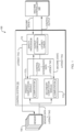
- this architecture can be used to implement a 3D vision safety system 300 that will slow or stop any hazards as a person approaches the controlled machinery (a robot in the illustrated embodiment) and will restart the machinery automatically once the person has cleared the area.
- This type of safeguarding is known as Speed and Separation Monitoring (SSM) and is defined in ISO 10218-2 and ISO/TS 15066.
- the sensors 305 may be 3D time-of-flight (ToF) sensors. There may be multiple (e.g., up to eight) ToF sensors 305 in a typical deployment. Each sensor 305 is responsible for providing a depth image from its own perspective, and the computation modules 112 process all of the depth images to generate and/or analyze the 3D volume.
- Suitable ToF sensors are described in U.S. Serial No. 16/553,724, filed on August 28, 2019 and published as US 2020/0077078 A1 .
- the SP 115 continuously triggers the 3D sensors 105 (typically in a sequential fashion so as to prevent crosstalk among the sensors).
- the sensor data is transmitted to the computation modules 112 for processing and generation, as necessary based on the analyzed sensor data, of speed override commands that are passed to the SP 115.
- the SP 115 also communicates with the robot controller 320 and provides robot state data, tagged with latency tags to the computation modules 112.
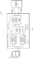
- the computation modules 112 each include modules that collectively transform data from all sensors 105 into a coherent 3D representation of the monitored workcell.
- these modules include an occupancy and occlusion analysis module 410, which analyzes the 3D volume of voxels representing the monitored workcell to identify objects and occluded regions (in accordance, for example, with U.S. Patent No. 10,099,372 ).
- the computation module 112 also includes a robot future state projection module 420, which, as also described in the '372 patent, predicts a future robot state based on the current state (positions and velocities) and the robot's kinematics; and a module 430 for computing Protective Separation Distances (PSDs) (as defined in ISO/TS 15066) between objects in the workcell and the future robot state predicted by the module 420.
- PSDs Protective Separation Distances
- the future robot state may be a voxel (or other) representation of all points reachable by the robot within a specified time period.
- the control outputs generated by the SP 115 are safety signals that override the task-performance commands issued by the conventionally programmed robot controller 320 in the course of normal robot operation.
- the SP 115 signals this information to the robot controller 320 via, for example, relays and output signal-switching devices (OSSDs), which issue "stop" commands to prevent hazardous movements.
- OSSDs are conventional components that stop or interrupt machinery when entry or proximity is a hazard.
- the control outputs could also include alternative trajectories designed to avoid collisions.
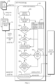
- the computation modules 112 then perform, in parallel, the calculations required to determine the control outputs to be sent to the machinery under control. As each computation module 112 performs these calculations, the latency tag is carried alongside the intermediate results derived from that data. Both computation modules 112 transmit the results of their computations to the SP 115, along with the latency tag that accompanied the data used in those computations, over an appropriate protocol (e.g., a Black Channel protocol). Meanwhile, in step 517, the latency checking module 510 records the generated latency tag in a lookup table 520 that stores each unique tag with its timestamp, i.e., the time it was sent to the sensors 105.
- a lookup table 520 that stores each unique tag with its timestamp, i.e., the time it was sent to the sensors 105.
- the latency checking module 510 monitors the time elapsed since the latency tag was sent to the sensors 105 to determine whether too much time passes between transmission and receipt of the latency tag (step 523). In normal operation, the SP 115 will receive the latency tag, along with control output signals and any intermediate data, from the computation modules 112 within a fixed timeout period consistent with normal operation. If the interval between transmission and receipt, or the absolute time elapsed since transmission if the latency tag never returns to the SP 115, exceeds the timeout period, a protective stop is asserted (step 525) to the machine controller 120.
- the latency checking module 510 compares both the latency tags and the outputs themselves from the two computation modules 112. If the latency tags are identical (step 530), and were issued by the SP 115 within the timeout period (steps 532, 535), and the control outputs and intermediate data agree (step 538), then the latency checking module 510 forwards the control outputs to the machine controller 120. If, however, one or both latency tags are incorrect, or were issued outside the timeout period, or if the control outputs or intermediate data do not agree, the latency checking module 510 acts on its own to place the machinery in a safe state (step 525).
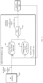
- the SP 115 may also perform periodic health self-checks including checking the consistency of the clock and timing signals driving the triggering and data collection with independent redundant external clock signals to ensure correct clock functionality of the SP 115; and monitoring of overall health of the system including temperature, humidity and power levels (e.g., via conventional sensors, which are not illustrated).
- periodic health self-checks including checking the consistency of the clock and timing signals driving the triggering and data collection with independent redundant external clock signals to ensure correct clock functionality of the SP 115; and monitoring of overall health of the system including temperature, humidity and power levels (e.g., via conventional sensors, which are not illustrated).
- EDM external device monitoring
- the SP 115 may include hardware elements, such as core undervoltage and overvoltage monitoring, ensuring that if the SP 115 cannot function in a safe state, additional health monitoring occurs such that the SP 115 and the safety-rated outputs can be put in a safe state. This includes but is not limited to a random failure of the SP 115 or any of its computing elements; a power failure; or a failure of an internal check. If the SP 115 or the health-monitoring hardware generates a failure signal, the SP 115 or the health-monitoring hardware can generate additional signals to put the entire safety architecture 100 in a safe state.
- hardware elements such as core undervoltage and overvoltage monitoring, ensuring that if the SP 115 cannot function in a safe state, additional health monitoring occurs such that the SP 115 and the safety-rated outputs can be put in a safe state. This includes but is not limited to a random failure of the SP 115 or any of its computing elements; a power failure; or a failure of an internal check. If the SP 115 or the health
- All of the modules in the computational modules 112 and the SP 115 may be programmed in any suitable programming language, including, without limitation, high-level languages such as C, C++, C#, Ada, Basic, Cobra, Fortran, Java, Lisp, Perl, Python, Ruby, or low-level assembly languages.
- the illustrated safety architecture 100 allows each of the computation modules 112 to be replaced with faster hardware or updated software without changing the SP 115 or other portion of the safety system.
- the illustrated configuration allows the safety architecture 100 to "fail safe," that is, if the latency checking module 510 of the SP 115 detects a computation fault, the SP 115 brings the system to a safe state.
- An alternative embodiment includes three computation modules 112 that allow for a single random failure in one of them. If the remaining two computation modules 112 agree on the results, the SP 115 will not issue a signal to shut the system down (a "fail operational" mode).
Landscapes
- Engineering & Computer Science (AREA)
- Physics & Mathematics (AREA)
- Robotics (AREA)
- Mechanical Engineering (AREA)
- General Physics & Mathematics (AREA)
- Human Computer Interaction (AREA)
- Manufacturing & Machinery (AREA)
- Automation & Control Theory (AREA)
- Computer Graphics (AREA)
- Geometry (AREA)
- Software Systems (AREA)
- Theoretical Computer Science (AREA)
- Safety Devices In Control Systems (AREA)
- Manipulator (AREA)
- Image Analysis (AREA)
Claims (15)
- Steuerungssystem, das Folgendes umfasst:eine Vielzahl von Sensoren (105), die konfiguriert sind, um Sensorausgaben zu produzieren;eine Vielzahl von nicht sicherheitsbezogenen Berechnungsmodulen (112), wobei die nicht sicherheitsbezogenen Berechnungsmodule jeweils einen Prozessor einschließen und simultan auf die Sensorausgaben reagieren und eine Sicherheitsanalyse ausführen, wobei die nicht sicherheitsbezogenen Berechnungsmodule Steuerungssignale produzieren als Reaktion auf das Erkennen einer Sicherheitsbedingung durch die Sicherheitsanalyse; undeinen Sicherheitsprozessor (115), der konfiguriert ist, um die Steuerungssignale von den Berechnungsmodulen (112) zu empfangen und davon sicherheitsbewertete Signale zum Steuern einer Vorrichtung zu erzeugen, wobei der Sicherheitsprozessor unfähig zum Ausführen der Sicherheitsanalyse ist.
- Steuerungssystem nach Anspruch 1, wobei der Sicherheitsprozessor (115) ferner konfiguriert ist, um die Leistung der Berechnungsmodule (112) zu überwachen einschließlich Latenztests und Überprüfung von identischen Ausgaben.
- Steuerungssystem nach Anspruch 1, wobei der Sicherheitsprozessor (115) ferner konfiguriert ist, um Zwischenergebnisse oder Datenstrukturen und Fehlerkorrekturcodes davon zu überwachen.
- Steuerungssystem nach Anspruch 1, wobei die Sicherheitsanalyse die Ausführung eines Algorithmus mit nichtdeterministischen oder variierenden Laufzeiten einschließt.
- Steuerungssystem nach Anspruch 1, wobei die Sensoren (105) 3D-Time-of-Flight-Kameras sind und die Berechnungsmodule (112) konfiguriert sind zum:i) Durchführen einer Bilderfassung von den Time-of-Flight-Kameradaten, einer Identifizierung und einer Klassifizierung in Echtzeit mit niedriger Latenz; oderii) Analysieren einer Belegung und Verdeckung eines überwachten Raums durch:Registrieren der Sensoren (105) in Bezug zueinander, sodass die durch die Sensoren erhaltenen Bilder gemeinsam den Arbeitsraum darstellen;Erzeugen einer dreidimensionalen Darstellung des Arbeitsraums als eine Vielzahl von Volumina;für jeden Sensorpixel, der ein Intensitätsniveau oberhalb eines Schwellenwerts aufweist, vorläufiges Markieren als unbesetzt von Volumina, die von einem Sichtlinien-Strahlengang durch das Pixel hindurch abgefangen werden, und in einem geschätzten Abstand zu dem zugeordneten Sensor einer Verdeckung enden, Markieren als besetzt der Volumina, die einem Endpunkt des Strahlengangs entsprechen, und Markieren als unbekannt jeglicher Volumina jenseits der Verdeckung entlang des Strahlengangs;für jeden Sensorpixel, der ein Intensitätsniveau unterhalb des Schwellenwerts aufweist, vorläufiges Markieren als unbekannt aller Voxel, die von einem Sichtlinien-Strahlengang durch das Pixel hindurch abgefangen werden und an einer Grenze des Arbeitsraums enden; undschließlich Markieren als unbesetzt von Volumina, die mindestens einmal vorläufig als unbesetzt markiert wurden; oderiii) Auswerten von Sicherheitsbedingungen in einem überwachten Raum durch:Registrieren der Sensoren in Bezug zueinander, sodass die durch die Sensoren erhaltenen Bilder gemeinsam den Arbeitsraum darstellen;Erzeugen einer dreidimensionalen Darstellung des Arbeitsraums als eine Vielzahl von Volumina; undErzeugen einer volumetrischen Darstellung aller Punkte, die durch bewegliche Maschinenausstattung im Arbeitsraum innerhalb einer festgelegten Zeitspanne erreichbar sind.
- Steuerungssystem nach Anspruch 1, wobei die Sicherheitsanalyse Folgendes umfasst:Geschwindigkeits- und Trennungsüberwachung gemäß mindestens einem von ISO/TS 15066 oder ISO 10218-2; oderschützende Trennungsdistanz-Überwachung gemäß mindestens einem von ISO/TS 15066 oder ISO 10218-2.
- Steuerungssystem nach Anspruch 1, wobei die Vielzahl von Berechnungsmodulen (112) konfiguriert sind, um einen Betrieb der Sensoren aufeinanderfolgend auszulösen, um Nebensprechen darunter zu verhindern.
- Steuerungssystem nach Anspruch 1, wobei die Vielzahl von Berechnungsmodulen (112) konfiguriert sind, um durch den Sicherheitsprozessor (115) ausgestellte Latenz-Tags zu empfangen.
- Steuerungssystem nach Anspruch 1, wobei der Sicherheitsprozessor (115) konfiguriert ist, um Latenz-Tags zu erzeugen und an die Sensoren zu übertragen für die Rückgabe an die Berechnungsmodule (112) mit Sensorausgaben.
- Steuerungssystem nach Anspruch 8, wobei der Sicherheitsprozessor (115) konfiguriert ist, um Latenz-Tags, die von den Berechnungsmodulen (112) zurückgegeben werden, zu empfangen und zu analysieren, um zu bestimmen, ob eine Dauer, die dem Verarbeiten durch die Vielzahl von Berechnungsmodulen zugeordnet ist, ein vorbestimmtes maximales Intervall überschreitet.
- Steuerungssystem nach Anspruch 1, wobei der Sicherheitsprozessor (115) konfiguriert ist, um Zwischenwerte, die von den Berechnungsmodulen (112) zurückgegeben werden, zu empfangen und zu analysieren, um zu bestimmen, ob ein Verarbeitungsfehler durch die Vielzahl von Berechnungsmodulen aufgetreten ist.
- Steuerungssystem nach Anspruch 1, wobei der Sicherheitsprozessor (115) konfiguriert ist, um zu überprüfen, dass die Vielzahl von Berechnungsmodulen (112) im Wesentlichen simultan arbeitet gemäß einem Latenzkriterium.
- Steuerungssystem nach Anspruch 1, wobei der Sicherheitsprozessor (115) konfiguriert ist, um zu überprüfen, dass Befehle, die im Wesentlichen simultan durch die Vielzahl von Berechnungsmodulen (112) ausgestellt werden, miteinander übereinstimmen und wobei, optional, die Berechnungsmodule Folgendes durchführen:identische Berechnungen; oderunterschiedliche Berechnungen, die dieselbe Sicherheitsfunktion umschließen.
- Steuerungssystem nach Anspruch 1, wobei der Sicherheitsprozessor (115) konfiguriert ist, um die Ausführung von Befehlen, die im Wesentlichen simultan von der Vielzahl von Berechnungsmodulen ausgestellt werden, durch die gesteuerte Vorrichtung zu veranlassen, nach der Überprüfung, dass (a) die Vielzahl von Berechnungsmodulen im Wesentlichen simultan arbeiten gemäß eines Latenzkriteriums und (b) die Befehle, die im Wesentlichen simultan durch die Vielzahl von Berechnungsmodulen ausgestellt werden, miteinander übereinstimmen.
- Steuerungssystem nach Anspruch 1, wobei der Sicherheitsprozessor (115) konfiguriert ist, um zu überprüfen, dass Takt- und Zeitsignale mit unabhängigen redundanten Referenzsignalen im Einklang stehen.
Applications Claiming Priority (2)
| Application Number | Priority Date | Filing Date | Title |
|---|---|---|---|
| US201962811070P | 2019-02-27 | 2019-02-27 | |
| PCT/US2020/019659 WO2020176473A1 (en) | 2019-02-27 | 2020-02-25 | System architecture for safety applications |
Publications (2)
| Publication Number | Publication Date |
|---|---|
| EP3887101A1 EP3887101A1 (de) | 2021-10-06 |
| EP3887101B1 true EP3887101B1 (de) | 2024-12-25 |
Family
ID=70057245
Family Applications (1)
| Application Number | Title | Priority Date | Filing Date |
|---|---|---|---|
| EP20715538.3A Active EP3887101B1 (de) | 2019-02-27 | 2020-02-25 | Systemarchitektur für sicherheitsanwendungen |
Country Status (4)
| Country | Link |
|---|---|
| US (3) | US11543798B2 (de) |
| EP (1) | EP3887101B1 (de) |
| JP (2) | JP7378168B2 (de) |
| WO (1) | WO2020176473A1 (de) |
Families Citing this family (17)
| Publication number | Priority date | Publication date | Assignee | Title |
|---|---|---|---|---|
| US10078908B2 (en) * | 2016-08-12 | 2018-09-18 | Elite Robotics | Determination of relative positions |
| US11613015B2 (en) * | 2017-09-18 | 2023-03-28 | Telefonaktiebolaget Lm Ericsson (Publ) | Technique for providing reliable control in a cloud robotics system |
| EP3588216B1 (de) * | 2018-06-28 | 2020-11-25 | Siemens Aktiengesellschaft | Verfahren und system zum fehlersicheren bereitstellen eines analogen ausgabewertes |
| EP3887101B1 (de) * | 2019-02-27 | 2024-12-25 | Veo Robotics, Inc. | Systemarchitektur für sicherheitsanwendungen |
| JP7260422B2 (ja) * | 2019-07-02 | 2023-04-18 | ファナック株式会社 | 異物検出装置 |
| US11577726B2 (en) | 2020-05-26 | 2023-02-14 | Ford Global Technologies, Llc | Vehicle assist feature control |
| US20220126451A1 (en) * | 2020-10-26 | 2022-04-28 | Realtime Robotics, Inc. | Safety systems and methods employed in robot operations |
| EP4040034B1 (de) * | 2021-02-04 | 2023-06-07 | Sick Ag | Sicherheitsvorrichtung und sicherheitsverfahren zur überwachung einer maschine |
| US12233876B2 (en) | 2021-03-25 | 2025-02-25 | Ford Global Technologies, Llc | Location-based vehicle operation |
| US12248304B2 (en) | 2021-03-26 | 2025-03-11 | Intel Corporation | Functional safety with root of safety and chain of safety |
| US20240231301A1 (en) * | 2021-05-04 | 2024-07-11 | Abb Schweiz Ag | Safety network for devices in intermittent use |
| US20230227071A1 (en) * | 2022-01-20 | 2023-07-20 | Gm Cruise Holdings Llc | Latency Violation Prevention for Autonomous Vehicle Control Systems |
| CN114860518A (zh) * | 2022-04-02 | 2022-08-05 | 浙江中控技术股份有限公司 | 功能安全系统的检测方法、系统、电子设备、存储介质 |
| US12449546B2 (en) * | 2022-04-15 | 2025-10-21 | Zebra Technologies Corporation | Lidar sensor system for enabling or disabling use of a robotic arm |
| WO2024075556A1 (ja) * | 2022-10-03 | 2024-04-11 | パナソニックIpマネジメント株式会社 | プロセッサ及びそれを備えた制御システム |
| WO2025111632A1 (en) * | 2023-11-29 | 2025-06-05 | Agile Projects Pty Ltd | Safety system |
| CN118081800B (zh) * | 2024-04-25 | 2024-07-12 | 浙江浙能数字科技有限公司 | 增强安全性摘复钩机器人系统及控制方法 |
Family Cites Families (16)
| Publication number | Priority date | Publication date | Assignee | Title |
|---|---|---|---|---|
| JP3736062B2 (ja) * | 1997-08-27 | 2006-01-18 | 富士電機システムズ株式会社 | 二重化プロセス入出力装置 |
| WO2009155993A1 (en) | 2008-06-27 | 2009-12-30 | Abb Research Ltd. | A safety system for a machine |
| CN103403628B (zh) * | 2011-01-31 | 2014-10-22 | 丰田自动车株式会社 | 安全控制装置以及安全控制方法 |
| US9452531B2 (en) | 2014-02-04 | 2016-09-27 | Microsoft Technology Licensing, Llc | Controlling a robot in the presence of a moving object |
| US10514683B2 (en) * | 2015-09-16 | 2019-12-24 | Profire Energy, Inc. | Distributed networking system and method to implement a safety state environment |
| US10262222B2 (en) | 2016-04-13 | 2019-04-16 | Sick Inc. | Method and system for measuring dimensions of a target object |
| ES2927177T3 (es) * | 2017-02-07 | 2022-11-03 | Veo Robotics Inc | Monitorización de la seguridad del espacio de trabajo y control de equipos |
| US11541543B2 (en) * | 2017-02-07 | 2023-01-03 | Veo Robotics, Inc. | Dynamic, interactive signaling of safety-related conditions in a monitored environment |
| US20230173682A1 (en) * | 2017-02-07 | 2023-06-08 | Marek WARTENBERG | Context-sensitive safety monitoring of collaborative work environments |
| JP6416980B1 (ja) * | 2017-05-17 | 2018-10-31 | ファナック株式会社 | 監視領域を分割した空間領域を監視する監視装置 |
| EP3437804A1 (de) | 2017-08-02 | 2019-02-06 | ABB Schweiz AG | Robotersteuerungsverfahren |
| US11014240B2 (en) | 2017-09-05 | 2021-05-25 | Abb Schweiz Ag | Robot having dynamic safety zones |
| US10445944B2 (en) | 2017-11-13 | 2019-10-15 | Rockwell Automation Technologies, Inc. | Augmented reality safety automation zone system and method |
| JP6818708B2 (ja) | 2018-02-28 | 2021-01-20 | 株式会社東芝 | マニピュレータシステム、制御装置、制御方法、およびプログラム |
| EP3887101B1 (de) * | 2019-02-27 | 2024-12-25 | Veo Robotics, Inc. | Systemarchitektur für sicherheitsanwendungen |
| US12377867B2 (en) * | 2019-09-23 | 2025-08-05 | Intel Corporation | Independent safety monitoring of an automated driving system |
-
2020
- 2020-02-25 EP EP20715538.3A patent/EP3887101B1/de active Active
- 2020-02-25 JP JP2021549788A patent/JP7378168B2/ja active Active
- 2020-02-25 WO PCT/US2020/019659 patent/WO2020176473A1/en not_active Ceased
- 2020-02-25 US US16/800,429 patent/US11543798B2/en active Active
-
2022
- 2022-11-22 US US17/991,895 patent/US11846916B2/en active Active
-
2023
- 2023-10-12 US US18/485,397 patent/US20240036545A1/en active Pending
- 2023-10-24 JP JP2023182453A patent/JP7649064B2/ja active Active
Also Published As
| Publication number | Publication date |
|---|---|
| EP3887101A1 (de) | 2021-10-06 |
| JP2023178407A (ja) | 2023-12-14 |
| US11543798B2 (en) | 2023-01-03 |
| JP2022522152A (ja) | 2022-04-14 |
| US11846916B2 (en) | 2023-12-19 |
| WO2020176473A1 (en) | 2020-09-03 |
| JP7649064B2 (ja) | 2025-03-19 |
| US20200272123A1 (en) | 2020-08-27 |
| US20230087242A1 (en) | 2023-03-23 |
| US20240036545A1 (en) | 2024-02-01 |
| JP7378168B2 (ja) | 2023-11-13 |
Similar Documents
| Publication | Publication Date | Title |
|---|---|---|
| US11846916B2 (en) | System architecture for safety applications | |
| JP7122776B2 (ja) | 作業空間安全監視および機器制御 | |
| CN104169630B (zh) | 用于使危险区域安全的方法和设备 | |
| JP7539742B2 (ja) | ロボット動作に使用される安全システム及び方法 | |
| CN107407919B (zh) | 安全控制系统和安全控制系统的运行方法 | |
| EP3936754B1 (de) | Kontinuierliche überwachung eines sicherheitssystems für arbeitszellen | |
| EP3862146B1 (de) | Zweifacher gebrauch eines sicherheitsfähigen fahrzeugscanners für gemeinschaftliche fahrzeugsmontage- und -fahrüberwachung | |
| Maragkos et al. | Virtual reality assisted robot programming for human collaboration | |
| US20260008469A1 (en) | Method for controlling a robotic device | |
| CN121069417A (zh) | 用于防护机器的安全系统和方法 | |
| Amat et al. | A Robot Working Space Protection System Using Visual Perception | |
| HK1224006B (en) | Device and method for securing a machine that operates in an automated manner |
Legal Events
| Date | Code | Title | Description |
|---|---|---|---|
| STAA | Information on the status of an ep patent application or granted ep patent |
Free format text: STATUS: UNKNOWN |
|
| STAA | Information on the status of an ep patent application or granted ep patent |
Free format text: STATUS: THE INTERNATIONAL PUBLICATION HAS BEEN MADE |
|
| PUAI | Public reference made under article 153(3) epc to a published international application that has entered the european phase |
Free format text: ORIGINAL CODE: 0009012 |
|
| STAA | Information on the status of an ep patent application or granted ep patent |
Free format text: STATUS: REQUEST FOR EXAMINATION WAS MADE |
|
| 17P | Request for examination filed |
Effective date: 20210701 |
|
| AK | Designated contracting states |
Kind code of ref document: A1 Designated state(s): AL AT BE BG CH CY CZ DE DK EE ES FI FR GB GR HR HU IE IS IT LI LT LU LV MC MK MT NL NO PL PT RO RS SE SI SK SM TR |
|
| DAV | Request for validation of the european patent (deleted) | ||
| DAX | Request for extension of the european patent (deleted) | ||
| STAA | Information on the status of an ep patent application or granted ep patent |
Free format text: STATUS: EXAMINATION IS IN PROGRESS |
|
| 17Q | First examination report despatched |
Effective date: 20230314 |
|
| P01 | Opt-out of the competence of the unified patent court (upc) registered |
Effective date: 20230526 |
|
| GRAP | Despatch of communication of intention to grant a patent |
Free format text: ORIGINAL CODE: EPIDOSNIGR1 |
|
| STAA | Information on the status of an ep patent application or granted ep patent |
Free format text: STATUS: GRANT OF PATENT IS INTENDED |
|
| INTG | Intention to grant announced |
Effective date: 20240719 |
|
| GRAS | Grant fee paid |
Free format text: ORIGINAL CODE: EPIDOSNIGR3 |
|
| GRAA | (expected) grant |
Free format text: ORIGINAL CODE: 0009210 |
|
| STAA | Information on the status of an ep patent application or granted ep patent |
Free format text: STATUS: THE PATENT HAS BEEN GRANTED |
|
| AK | Designated contracting states |
Kind code of ref document: B1 Designated state(s): AL AT BE BG CH CY CZ DE DK EE ES FI FR GB GR HR HU IE IS IT LI LT LU LV MC MK MT NL NO PL PT RO RS SE SI SK SM TR |
|
| REG | Reference to a national code |
Ref country code: GB Ref legal event code: FG4D |
|
| REG | Reference to a national code |
Ref country code: CH Ref legal event code: EP |
|
| REG | Reference to a national code |
Ref country code: DE Ref legal event code: R096 Ref document number: 602020043637 Country of ref document: DE |
|
| REG | Reference to a national code |
Ref country code: IE Ref legal event code: FG4D |
|
| REG | Reference to a national code |
Ref country code: LT Ref legal event code: MG9D |
|
| PG25 | Lapsed in a contracting state [announced via postgrant information from national office to epo] |
Ref country code: HR Free format text: LAPSE BECAUSE OF FAILURE TO SUBMIT A TRANSLATION OF THE DESCRIPTION OR TO PAY THE FEE WITHIN THE PRESCRIBED TIME-LIMIT Effective date: 20241225 |
|
| PG25 | Lapsed in a contracting state [announced via postgrant information from national office to epo] |
Ref country code: FI Free format text: LAPSE BECAUSE OF FAILURE TO SUBMIT A TRANSLATION OF THE DESCRIPTION OR TO PAY THE FEE WITHIN THE PRESCRIBED TIME-LIMIT Effective date: 20241225 |
|
| PG25 | Lapsed in a contracting state [announced via postgrant information from national office to epo] |
Ref country code: BG Free format text: LAPSE BECAUSE OF FAILURE TO SUBMIT A TRANSLATION OF THE DESCRIPTION OR TO PAY THE FEE WITHIN THE PRESCRIBED TIME-LIMIT Effective date: 20241225 |
|
| PG25 | Lapsed in a contracting state [announced via postgrant information from national office to epo] |
Ref country code: NO Free format text: LAPSE BECAUSE OF FAILURE TO SUBMIT A TRANSLATION OF THE DESCRIPTION OR TO PAY THE FEE WITHIN THE PRESCRIBED TIME-LIMIT Effective date: 20250325 |
|
| PG25 | Lapsed in a contracting state [announced via postgrant information from national office to epo] |
Ref country code: LV Free format text: LAPSE BECAUSE OF FAILURE TO SUBMIT A TRANSLATION OF THE DESCRIPTION OR TO PAY THE FEE WITHIN THE PRESCRIBED TIME-LIMIT Effective date: 20241225 Ref country code: GR Free format text: LAPSE BECAUSE OF FAILURE TO SUBMIT A TRANSLATION OF THE DESCRIPTION OR TO PAY THE FEE WITHIN THE PRESCRIBED TIME-LIMIT Effective date: 20250326 |
|
| PG25 | Lapsed in a contracting state [announced via postgrant information from national office to epo] |
Ref country code: RS Free format text: LAPSE BECAUSE OF FAILURE TO SUBMIT A TRANSLATION OF THE DESCRIPTION OR TO PAY THE FEE WITHIN THE PRESCRIBED TIME-LIMIT Effective date: 20250325 |
|
| REG | Reference to a national code |
Ref country code: NL Ref legal event code: MP Effective date: 20241225 |
|
| PG25 | Lapsed in a contracting state [announced via postgrant information from national office to epo] |
Ref country code: NL Free format text: LAPSE BECAUSE OF FAILURE TO SUBMIT A TRANSLATION OF THE DESCRIPTION OR TO PAY THE FEE WITHIN THE PRESCRIBED TIME-LIMIT Effective date: 20241225 |
|
| REG | Reference to a national code |
Ref country code: AT Ref legal event code: MK05 Ref document number: 1753788 Country of ref document: AT Kind code of ref document: T Effective date: 20241225 |
|
| PG25 | Lapsed in a contracting state [announced via postgrant information from national office to epo] |
Ref country code: SM Free format text: LAPSE BECAUSE OF FAILURE TO SUBMIT A TRANSLATION OF THE DESCRIPTION OR TO PAY THE FEE WITHIN THE PRESCRIBED TIME-LIMIT Effective date: 20241225 |
|
| PG25 | Lapsed in a contracting state [announced via postgrant information from national office to epo] |
Ref country code: PL Free format text: LAPSE BECAUSE OF FAILURE TO SUBMIT A TRANSLATION OF THE DESCRIPTION OR TO PAY THE FEE WITHIN THE PRESCRIBED TIME-LIMIT Effective date: 20241225 |
|
| PGFP | Annual fee paid to national office [announced via postgrant information from national office to epo] |
Ref country code: DE Payment date: 20250429 Year of fee payment: 6 |
|
| PG25 | Lapsed in a contracting state [announced via postgrant information from national office to epo] |
Ref country code: ES Free format text: LAPSE BECAUSE OF FAILURE TO SUBMIT A TRANSLATION OF THE DESCRIPTION OR TO PAY THE FEE WITHIN THE PRESCRIBED TIME-LIMIT Effective date: 20241225 |
|
| PGFP | Annual fee paid to national office [announced via postgrant information from national office to epo] |
Ref country code: GB Payment date: 20250428 Year of fee payment: 6 |
|
| PG25 | Lapsed in a contracting state [announced via postgrant information from national office to epo] |
Ref country code: IS Free format text: LAPSE BECAUSE OF FAILURE TO SUBMIT A TRANSLATION OF THE DESCRIPTION OR TO PAY THE FEE WITHIN THE PRESCRIBED TIME-LIMIT Effective date: 20250425 |
|
| PG25 | Lapsed in a contracting state [announced via postgrant information from national office to epo] |
Ref country code: PT Free format text: LAPSE BECAUSE OF FAILURE TO SUBMIT A TRANSLATION OF THE DESCRIPTION OR TO PAY THE FEE WITHIN THE PRESCRIBED TIME-LIMIT Effective date: 20250428 |
|
| PG25 | Lapsed in a contracting state [announced via postgrant information from national office to epo] |
Ref country code: EE Free format text: LAPSE BECAUSE OF FAILURE TO SUBMIT A TRANSLATION OF THE DESCRIPTION OR TO PAY THE FEE WITHIN THE PRESCRIBED TIME-LIMIT Effective date: 20241225 |
|
| PGFP | Annual fee paid to national office [announced via postgrant information from national office to epo] |
Ref country code: FR Payment date: 20250425 Year of fee payment: 6 |
|
| PGFP | Annual fee paid to national office [announced via postgrant information from national office to epo] |
Ref country code: CH Payment date: 20250429 Year of fee payment: 6 |
|
| PG25 | Lapsed in a contracting state [announced via postgrant information from national office to epo] |
Ref country code: RO Free format text: LAPSE BECAUSE OF FAILURE TO SUBMIT A TRANSLATION OF THE DESCRIPTION OR TO PAY THE FEE WITHIN THE PRESCRIBED TIME-LIMIT Effective date: 20241225 Ref country code: AT Free format text: LAPSE BECAUSE OF FAILURE TO SUBMIT A TRANSLATION OF THE DESCRIPTION OR TO PAY THE FEE WITHIN THE PRESCRIBED TIME-LIMIT Effective date: 20241225 |
|
| PG25 | Lapsed in a contracting state [announced via postgrant information from national office to epo] |
Ref country code: SK Free format text: LAPSE BECAUSE OF FAILURE TO SUBMIT A TRANSLATION OF THE DESCRIPTION OR TO PAY THE FEE WITHIN THE PRESCRIBED TIME-LIMIT Effective date: 20241225 |
|
| PG25 | Lapsed in a contracting state [announced via postgrant information from national office to epo] |
Ref country code: CZ Free format text: LAPSE BECAUSE OF FAILURE TO SUBMIT A TRANSLATION OF THE DESCRIPTION OR TO PAY THE FEE WITHIN THE PRESCRIBED TIME-LIMIT Effective date: 20241225 |
|
| PG25 | Lapsed in a contracting state [announced via postgrant information from national office to epo] |
Ref country code: IT Free format text: LAPSE BECAUSE OF FAILURE TO SUBMIT A TRANSLATION OF THE DESCRIPTION OR TO PAY THE FEE WITHIN THE PRESCRIBED TIME-LIMIT Effective date: 20241225 |
|
| PG25 | Lapsed in a contracting state [announced via postgrant information from national office to epo] |
Ref country code: SE Free format text: LAPSE BECAUSE OF FAILURE TO SUBMIT A TRANSLATION OF THE DESCRIPTION OR TO PAY THE FEE WITHIN THE PRESCRIBED TIME-LIMIT Effective date: 20241225 |
|
| PG25 | Lapsed in a contracting state [announced via postgrant information from national office to epo] |
Ref country code: MC Free format text: LAPSE BECAUSE OF FAILURE TO SUBMIT A TRANSLATION OF THE DESCRIPTION OR TO PAY THE FEE WITHIN THE PRESCRIBED TIME-LIMIT Effective date: 20241225 |
|
| REG | Reference to a national code |
Ref country code: DE Ref legal event code: R097 Ref document number: 602020043637 Country of ref document: DE |
|
| PG25 | Lapsed in a contracting state [announced via postgrant information from national office to epo] |
Ref country code: DK Free format text: LAPSE BECAUSE OF FAILURE TO SUBMIT A TRANSLATION OF THE DESCRIPTION OR TO PAY THE FEE WITHIN THE PRESCRIBED TIME-LIMIT Effective date: 20241225 |
|
| PG25 | Lapsed in a contracting state [announced via postgrant information from national office to epo] |
Ref country code: LU Free format text: LAPSE BECAUSE OF NON-PAYMENT OF DUE FEES Effective date: 20250225 |
|
| PLBE | No opposition filed within time limit |
Free format text: ORIGINAL CODE: 0009261 |
|
| STAA | Information on the status of an ep patent application or granted ep patent |
Free format text: STATUS: NO OPPOSITION FILED WITHIN TIME LIMIT |
|
| 26N | No opposition filed |
Effective date: 20250926 |
|
| REG | Reference to a national code |
Ref country code: BE Ref legal event code: MM Effective date: 20250228 |
|
| PG25 | Lapsed in a contracting state [announced via postgrant information from national office to epo] |
Ref country code: BE Free format text: LAPSE BECAUSE OF NON-PAYMENT OF DUE FEES Effective date: 20250228 |
|
| PG25 | Lapsed in a contracting state [announced via postgrant information from national office to epo] |
Ref country code: IE Free format text: LAPSE BECAUSE OF NON-PAYMENT OF DUE FEES Effective date: 20250225 |