EP3886973B1 - Bidirektionale medizinische ventile - Google Patents
Bidirektionale medizinische ventile Download PDFInfo
- Publication number
- EP3886973B1 EP3886973B1 EP19890202.5A EP19890202A EP3886973B1 EP 3886973 B1 EP3886973 B1 EP 3886973B1 EP 19890202 A EP19890202 A EP 19890202A EP 3886973 B1 EP3886973 B1 EP 3886973B1
- Authority
- EP
- European Patent Office
- Prior art keywords
- septum
- proximal
- valve
- distal
- medical valve
- Prior art date
- Legal status (The legal status is an assumption and is not a legal conclusion. Google has not performed a legal analysis and makes no representation as to the accuracy of the status listed.)
- Active
Links
Images


Classifications
-
- A—HUMAN NECESSITIES
- A61—MEDICAL OR VETERINARY SCIENCE; HYGIENE
- A61M—DEVICES FOR INTRODUCING MEDIA INTO, OR ONTO, THE BODY; DEVICES FOR TRANSDUCING BODY MEDIA OR FOR TAKING MEDIA FROM THE BODY; DEVICES FOR PRODUCING OR ENDING SLEEP OR STUPOR
- A61M39/00—Tubes, tube connectors, tube couplings, valves, access sites or the like, specially adapted for medical use
- A61M39/02—Access sites
- A61M39/06—Haemostasis valves, i.e. gaskets sealing around a needle, catheter or the like, closing on removal thereof
- A61M39/0613—Haemostasis valves, i.e. gaskets sealing around a needle, catheter or the like, closing on removal thereof with means for adjusting the seal opening or pressure
-
- A—HUMAN NECESSITIES
- A61—MEDICAL OR VETERINARY SCIENCE; HYGIENE
- A61M—DEVICES FOR INTRODUCING MEDIA INTO, OR ONTO, THE BODY; DEVICES FOR TRANSDUCING BODY MEDIA OR FOR TAKING MEDIA FROM THE BODY; DEVICES FOR PRODUCING OR ENDING SLEEP OR STUPOR
- A61M39/00—Tubes, tube connectors, tube couplings, valves, access sites or the like, specially adapted for medical use
- A61M39/22—Valves or arrangement of valves
- A61M39/223—Multiway valves
-
- A—HUMAN NECESSITIES
- A61—MEDICAL OR VETERINARY SCIENCE; HYGIENE
- A61B—DIAGNOSIS; SURGERY; IDENTIFICATION
- A61B5/00—Measuring for diagnostic purposes; Identification of persons
- A61B5/15—Devices for taking samples of blood
- A61B5/150007—Details
- A61B5/150015—Source of blood
- A61B5/15003—Source of blood for venous or arterial blood
-
- A—HUMAN NECESSITIES
- A61—MEDICAL OR VETERINARY SCIENCE; HYGIENE
- A61B—DIAGNOSIS; SURGERY; IDENTIFICATION
- A61B5/00—Measuring for diagnostic purposes; Identification of persons
- A61B5/15—Devices for taking samples of blood
- A61B5/150007—Details
- A61B5/150206—Construction or design features not otherwise provided for; manufacturing or production; packages; sterilisation of piercing element, piercing device or sampling device
- A61B5/150221—Valves
-
- A—HUMAN NECESSITIES
- A61—MEDICAL OR VETERINARY SCIENCE; HYGIENE
- A61B—DIAGNOSIS; SURGERY; IDENTIFICATION
- A61B5/00—Measuring for diagnostic purposes; Identification of persons
- A61B5/15—Devices for taking samples of blood
- A61B5/150992—Blood sampling from a fluid line external to a patient, such as a catheter line, combined with an infusion line; Blood sampling from indwelling needle sets, e.g. sealable ports, luer couplings or valves
-
- A—HUMAN NECESSITIES
- A61—MEDICAL OR VETERINARY SCIENCE; HYGIENE
- A61M—DEVICES FOR INTRODUCING MEDIA INTO, OR ONTO, THE BODY; DEVICES FOR TRANSDUCING BODY MEDIA OR FOR TAKING MEDIA FROM THE BODY; DEVICES FOR PRODUCING OR ENDING SLEEP OR STUPOR
- A61M39/00—Tubes, tube connectors, tube couplings, valves, access sites or the like, specially adapted for medical use
- A61M39/02—Access sites
- A61M39/0247—Semi-permanent or permanent transcutaneous or percutaneous access sites to the inside of the body
-
- A—HUMAN NECESSITIES
- A61—MEDICAL OR VETERINARY SCIENCE; HYGIENE
- A61M—DEVICES FOR INTRODUCING MEDIA INTO, OR ONTO, THE BODY; DEVICES FOR TRANSDUCING BODY MEDIA OR FOR TAKING MEDIA FROM THE BODY; DEVICES FOR PRODUCING OR ENDING SLEEP OR STUPOR
- A61M39/00—Tubes, tube connectors, tube couplings, valves, access sites or the like, specially adapted for medical use
- A61M39/22—Valves or arrangement of valves
- A61M39/225—Flush valves, i.e. bypass valves for flushing line
-
- A—HUMAN NECESSITIES
- A61—MEDICAL OR VETERINARY SCIENCE; HYGIENE
- A61M—DEVICES FOR INTRODUCING MEDIA INTO, OR ONTO, THE BODY; DEVICES FOR TRANSDUCING BODY MEDIA OR FOR TAKING MEDIA FROM THE BODY; DEVICES FOR PRODUCING OR ENDING SLEEP OR STUPOR
- A61M39/00—Tubes, tube connectors, tube couplings, valves, access sites or the like, specially adapted for medical use
- A61M39/22—Valves or arrangement of valves
- A61M39/24—Check- or non-return valves
-
- A—HUMAN NECESSITIES
- A61—MEDICAL OR VETERINARY SCIENCE; HYGIENE
- A61M—DEVICES FOR INTRODUCING MEDIA INTO, OR ONTO, THE BODY; DEVICES FOR TRANSDUCING BODY MEDIA OR FOR TAKING MEDIA FROM THE BODY; DEVICES FOR PRODUCING OR ENDING SLEEP OR STUPOR
- A61M39/00—Tubes, tube connectors, tube couplings, valves, access sites or the like, specially adapted for medical use
- A61M39/02—Access sites
- A61M39/0247—Semi-permanent or permanent transcutaneous or percutaneous access sites to the inside of the body
- A61M2039/027—Semi-permanent or permanent transcutaneous or percutaneous access sites to the inside of the body having a particular valve, seal or septum
-
- A—HUMAN NECESSITIES
- A61—MEDICAL OR VETERINARY SCIENCE; HYGIENE
- A61M—DEVICES FOR INTRODUCING MEDIA INTO, OR ONTO, THE BODY; DEVICES FOR TRANSDUCING BODY MEDIA OR FOR TAKING MEDIA FROM THE BODY; DEVICES FOR PRODUCING OR ENDING SLEEP OR STUPOR
- A61M39/00—Tubes, tube connectors, tube couplings, valves, access sites or the like, specially adapted for medical use
- A61M39/02—Access sites
- A61M39/06—Haemostasis valves, i.e. gaskets sealing around a needle, catheter or the like, closing on removal thereof
- A61M2039/0633—Haemostasis valves, i.e. gaskets sealing around a needle, catheter or the like, closing on removal thereof the seal being a passive seal made of a resilient material with or without an opening
- A61M2039/064—Slit-valve
-
- A—HUMAN NECESSITIES
- A61—MEDICAL OR VETERINARY SCIENCE; HYGIENE
- A61M—DEVICES FOR INTRODUCING MEDIA INTO, OR ONTO, THE BODY; DEVICES FOR TRANSDUCING BODY MEDIA OR FOR TAKING MEDIA FROM THE BODY; DEVICES FOR PRODUCING OR ENDING SLEEP OR STUPOR
- A61M39/00—Tubes, tube connectors, tube couplings, valves, access sites or the like, specially adapted for medical use
- A61M39/02—Access sites
- A61M39/06—Haemostasis valves, i.e. gaskets sealing around a needle, catheter or the like, closing on removal thereof
- A61M2039/0633—Haemostasis valves, i.e. gaskets sealing around a needle, catheter or the like, closing on removal thereof the seal being a passive seal made of a resilient material with or without an opening
- A61M2039/066—Septum-like element
-
- A—HUMAN NECESSITIES
- A61—MEDICAL OR VETERINARY SCIENCE; HYGIENE
- A61M—DEVICES FOR INTRODUCING MEDIA INTO, OR ONTO, THE BODY; DEVICES FOR TRANSDUCING BODY MEDIA OR FOR TAKING MEDIA FROM THE BODY; DEVICES FOR PRODUCING OR ENDING SLEEP OR STUPOR
- A61M39/00—Tubes, tube connectors, tube couplings, valves, access sites or the like, specially adapted for medical use
- A61M39/10—Tube connectors; Tube couplings
- A61M2039/1072—Tube connectors; Tube couplings with a septum present in the connector
-
- A—HUMAN NECESSITIES
- A61—MEDICAL OR VETERINARY SCIENCE; HYGIENE
- A61M—DEVICES FOR INTRODUCING MEDIA INTO, OR ONTO, THE BODY; DEVICES FOR TRANSDUCING BODY MEDIA OR FOR TAKING MEDIA FROM THE BODY; DEVICES FOR PRODUCING OR ENDING SLEEP OR STUPOR
- A61M39/00—Tubes, tube connectors, tube couplings, valves, access sites or the like, specially adapted for medical use
- A61M39/22—Valves or arrangement of valves
- A61M39/24—Check- or non-return valves
- A61M2039/242—Check- or non-return valves designed to open when a predetermined pressure or flow rate has been reached, e.g. check valve actuated by fluid
-
- A—HUMAN NECESSITIES
- A61—MEDICAL OR VETERINARY SCIENCE; HYGIENE
- A61M—DEVICES FOR INTRODUCING MEDIA INTO, OR ONTO, THE BODY; DEVICES FOR TRANSDUCING BODY MEDIA OR FOR TAKING MEDIA FROM THE BODY; DEVICES FOR PRODUCING OR ENDING SLEEP OR STUPOR
- A61M39/00—Tubes, tube connectors, tube couplings, valves, access sites or the like, specially adapted for medical use
- A61M39/22—Valves or arrangement of valves
- A61M39/24—Check- or non-return valves
- A61M2039/2426—Slit valve
Definitions
- Certain embodiments described herein relate generally to valves, and further embodiments relate more particularly to bidirectional medical valves, such as may be used, for example, with catheters, such as peripherally inserted central catheters (PICCs).
- catheters such as peripherally inserted central catheters (PICCs).
- PICCs peripherally inserted central catheters
- Certain medical valves are used to permit fluid flow in either a first direction, such as for infusion through the valve, or a second direction, such as for aspiration through the valve.
- Known bidirectional medical valves suffer from one or more drawbacks.
- Various limitations of such bidirectional medical valves can be resolved, remedied, ameliorated, or avoided by certain embodiments described herein.
- US2013338608A1 ANGIODYNAMICS INC describes a pressure activated two-way slit valve assembly is designed to be used in combination with, but not limited to, a high flow rate catheter to prevent accidental ingestion of air or loss of blood if the closure cap comes off during non-use of the catheter.
- the pressure activated two-way slit valve assembly includes a first end, a second end, a wall defining a dumbbell shaped channel, and a flexible, thin disk having a slit and positioned within the pressure activated two-way slit valve assembly to reside within the dumbbell shaped channel.
- the slit and the dumbbell shaped channel are sized to enable the slit to deform in response to a predetermined pressure differential across the slit to allow fluid to pass therethrough.
- US4354492A AMERICAN HOSPITAL SUPPLY CORP describes an administration set with a check valve above a side port where the side port is used for the introduction of a secondary liquid, and this check valve is extremely sensitive to minute pressure changes in the combined administration set.
- the valve includes a very light disk supported on a series of upstanding prongs that hold a sealing surface of the disk to within 0.002 to 0.030 inch of a valve seat when in open position.
- the highly sensitive valve is easy to manufacture, easy to prime, and resists malfunctioning due to sticking shut or open.
- the valve also permits high flow rates (up to 500 ml/hr. or more) commonly used in medical administration sets.
- US2018043149A1 ANGIODYNAMICS INC describes a bi-directional, pressure-actuated medical valve assembly for improved control of fluids and related methods of use are described.
- the pressure-actuated, bi-directional valve includes a first flow control portion permitting fluid to flow in a first direction when subjected to a first pressure threshold and a second control flow portion for permitting fluid to flow in a second direction when subjected to a second pressure threshold.
- US2005010176A1 DIKEMAN W. CARY & SPIKER KENY describes a pressure actuated flow control valve for an infusion catheter permits gravity flow of a liquid through the catheter and into a patient while resisting back flow of blood from the patient and into the catheter.
- the valve has a hemispherical body with an outstanding circumferential flange and a normally closed, diametric slit.
- the slit is longer on the convex outer surface than on the concave inner surface. Dome thickness diminishes in the area adjacent the slit, reducing total apical deflection upon collapse of the slit toward the concave surface.
- An inner orthogonal rib biases the slit closed. Upon application of a predetermined pressure, the slit opens toward the concave surface to permit forward fluid flow. At lower pressures, the slit closes to check fluid flow. Greater reverse pressure is required to collapse the slit toward the concave surface to permit reverse fluid flow.
- valves relate generally to valves, and more particularly relates to bidirectional valves.
- Certain embodiments of valves disclosed herein can be particularly useful for a variety of medical applications.
- embodiments of the valves may be particularly well suited for use in applications in which different cracking pressures in opposite directions of fluid flow are desired.
- the valves can be used advantageously with catheters via which fluids are infused into a patient and/or via which blood is drawn or aspirated from the patient.
- Certain embodiments may perform well at flushing blood from the bidirectional valve after blood draws have been taken through the valve.
- the valves may further be suitable for power injection.
- certain valves may be used as proximal valves in PICC catheters, such as power injectable PICC catheters.
- Proximal valves for PICC catheters are known in the art.
- Proximal valves generally are coupled to the proximal ends of catheter assemblies in which a catheter body is insertable into a body of a patient, and the valves remain at an exterior of the patient when the catheter body is in place within the patient to provide access to one or more lumens of the catheter.
- Such proximal valves generally can be used to infuse one or more fluids into a patient and/or to aspirate blood or other fluids from the patient.
- Known proximal valves suffer from a variety of drawbacks.
- some known proximal valves include geometries, architectures, or internal configurations that inhibit blood and/or microbes from being flushed from the valves.
- blood that is drawn into a proximal chamber of the valve during aspiration can enter between a shelf-like feature within a housing of the valve and a septum.
- the shelf-like feature does not permit fluid to get in between the septum and the shelf-like feature, thereby trapping blood between these components.
- microbes within the valve can be urged into such regions and permitted to colonize, rather than being flushed out.
- cracking pressure is used herein in its ordinary sense, and includes, for example, a pressure differential across a feature at which a closure in that feature opens to permit fluid to flow through the closure.
- closure is used herein in its ordinary sense, and includes, for example, any suitable feature that can be closed and/or selectively opened. Thus, the term “closure” is not meant to imply a feature that is permanently closed, but rather, a feature that can be in a closed configuration to prevent fluid flow therethrough and may be transitioned to an open configuration to permit fluid flow therethrough.
- a closure may be biased toward the closed configuration, and this bias may be overcome to open the closure. In other embodiments, the closure may be biased toward the open configuration, and this bias may be overcome to close the closure.
- one known bidirectional proximal valve includes an elastomeric septum that includes three closures. To permit fluid flow through the valve in one direction, a first of the three closures opens while the second and third closures remain closed, whereas to permit fluid flow through the valve in the opposite direction, the second and third closures open and the first valve closes.
- the cracking pressure of the first closure and/or the cracking pressure (or pressures) of the second and third closures can be widely inconsistent from one valve to the next.
- proximal valves may be incorporated into catheter assemblies prior to determining that one or more cracking pressures are outside of the manufacturer's tolerances, and the catheter assemblies must then be discarded. This can lead to significant material waste and heightened manufacturing costs.
- inconsistent cracking pressures or even cracking pressures that vary within a large range of "acceptable" values (as determined by a manufacturer), can lead to unreliable tactile feedback during use of the catheter assemblies.
- practitioners in many instances use tactile feedback to determine whether infusion and/or aspiration through a catheter assembly requires greater pressure than expected. Practitioners can develop a sense for whether or not a catheter is occluded based on how easy or difficult it is to infuse or aspirate through the catheter. Variation in cracking pressures in the proximal valve, however, can make it difficult for practitioners to gain an accurate sense for when occlusions may be present.
- inconsistent cracking pressures and/or valve degradation or failure of known proximal valves may result from the presence of stylets or guidewires within the valves.
- catheter assemblies may be prepackaged with a stylet extending through a proximal valve.
- a proximal valve may include a slit through which the stylet passes. Over time, the presence of the stylet may deform one or more adjacent contact surfaces of the slit such that the contact surfaces may not align properly to seal the slit. Thus, the proximal valve may no longer operate as designed.
- Certain embodiments described herein address, ameliorate, resolve, or avoid one or more of the foregoing disadvantages of known proximal valves.
- various embodiments disclosed herein are configured to more effectively flush blood from a proximal chamber, to be manufactured with consistent and repeatable cracking pressures, and/or to be prepackaged with stylets extending therethrough or to permit guidewires to be passed therethrough without any degradation in valving performance.
- Various embodiments can achieve one or more of these and/or other advantages, including those expressly discussed herein and those otherwise apparent from the present disclosure.
- FIG. 1 depicts an embodiment of a catheter assembly 100 that includes a catheter body 102 (which may also be referred to as a catheter, catheter sheath, etc.), a junction 104, a pair of extension legs 106, 107, and a pair of proximal valves 110, 111 attached to the respective proximal ends of the extension legs 106, 107.
- the illustrated catheter body 102 includes two lumens (not shown), and each lumen is in fluid communication with a respective one of the extension legs 106, 107 and a respective one of the proximal valves 110, 111 via fluid channels (not shown) that extend through the junction 104.
- the catheter assembly 100 can further include a pair of clamps 112, 113: one for each extension leg 106, 107, respectively.
- the two lumens through the catheter body 102 extend fully from a proximal end of the catheter body 102 to a distal end thereof. The lumens thus may terminate at a distal tip of the catheter body 102. Other suitable arrangements or configurations of the lumens are contemplated.
- the catheter assembly 100 can be configured for any suitable use.
- the catheter assembly 100 is suitable for use as a PICC.
- the catheter assembly 100 and some or all components thereof, including the proximal valves 110, 111, may be suitable for power injections.
- the term "power injection” is consistent with the generally accepted definition of this term, and refers to pressurized infusions that occur at high flow rates, such as up to 4.0 mL/s or up to 5.0 mL/sec; that often involve injection of viscous materials, such as materials (e.g., contrast media) having a viscosity of 11.8 cP +/- 0.3 cP; and that take place at elevated pressures.
- a “power injectable” catheter assembly is one that is capable of sustaining power injection without leaking, bursting, or swelling to a size that is not usable within the vasculature.
- a power injectable catheter assembly may be one that complies with the power injection specifications of the International Standards Organization (ISO) standard ISO 10555-1.
- ISO International Standards Organization
- a power injectable PICC is a PICC configured to sustain power injections.
- power injectable PICCs can be and/or remain operable at pressures of up to about 180, 190, 200, 210, 220, 230, 240, 250, or even 260 psi.
- PICCs may also be used for other functions, such as intravenous therapy at lower pressures or standard infusion and aspiration or blood sampling.
- the proximal valves 110, 111 are substantially identical to each other. In other embodiments, the proximal valves 110, 111 may be different from each other. For example, the proximal valves 110, 111 may have different performance characteristics, such as with respect to power injectability and/or with respect to cracking pressures. In some instances, one of the proximal valves 110, 111 may be configured for power injections (e.g., can operate at and suffer little or no performance degradation due to elevated power injection pressures), whereas the other of the proximal valves 110, 111 may only be configured for operation at lower pressures.
- power injections e.g., can operate at and suffer little or no performance degradation due to elevated power injection pressures
- the catheter assembly 100 may include a stylet (see FIG. 18 ) that extends through the proximal valve 110, the extension leg 106, one of the fluid channels of the junction 104, and one of the lumens of the catheter body 102.
- the stylet may instead extend through the other proximal valve 111 and its associated fluid path through the catheter assembly 100.
- the stylet may be inserted just prior to introducing the catheter assembly 100 into a patient.
- the stylet may be prepackaged with the catheter assembly 100 so as to extend through one of the fluid paths of the catheter assembly 100.
- Embodiments of such catheter assemblies 100 that include a stylet can be used in manners known in the art, such as for stiffening the catheter body 102 for advancement through or otherwise positioning the catheter body 102 within the vasculature of a patient.
- the catheter assembly 100 may be advanced over a guidewire in manners such as those known in the art.
- each proximal valve 110, 111 is a bidirectional valve. Stated otherwise, each proximal valve 110, 111 is configured to permit fluid to pass through the valve in each of a distal direction and a proximal direction.
- the direction of fluid flow may also be referred to as an ingress or infusion direction (e.g., toward or directed into the patient) or as an egress or aspiration direction (e.g., away from or directed out of the patient).
- the bidirectional valves 110, 111 can be asymmetrical, such that a cracking pressure in one direction is different from a cracking pressure in the opposite direction. Stated otherwise, each valve 110, 111 is an asymmetric bidirectional valve.
- the aspiration cracking pressure is higher than the infusion cracking pressure. It may be said that it is easier to introduce fluids into the patient through the proximal valves 110, 111 than it is to remove fluids from the patient through the proximal valves 110, 111.
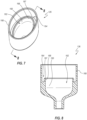
- FIGS. 2 and 3 depict an embodiment of the valve 110, which can include a housing 120 and a septum 122.
- the septum 122 may alternatively be referred to as a valve or as a valving member.
- the housing 120 includes a plurality of pieces that are joined together.
- the housing 120 is a two-part housing that includes a first piece 124 and a second piece 126.
- the first and second pieces 124, 126 may also be referred to as separate housing members, elements, components, etc.
- the housing member 124 may also be referred to as a proximal housing member
- the housing member 126 may also be referred to as a distal housing member.
- housing members 124, 126 may be joined together in any suitable fashion, including (without limitation) via one or more of adhesive bonding, solvent bonding, ultrasonic welding, etc.
- the septum 122 can be fixedly secured to the housing 120.
- the septum 122 is captured or held between the first and second housing member 124, 126, as further discussed below.
- the septum 122 is gripped between the housing members 124, 126 without either housing member 124, 126 penetrating through the septum 122.
- one or more of the housing members 124, 126 may pass through the septum 122 to retain or further retain the septum 122 in a desired position, such as discussed below, for example, with respect to FIGS. 18-30 .
- the septum 122 may be anchored or otherwise securely attached to one or more of the housing members 124, 126, whether instead of or in addition to being gripped between the housing members 124, 126.
- each of the housing members 124, 126 has a substantially oval-shaped profile. Stated otherwise, a perimeter or transverse cross-sectional shape of each housing member 124, 126 is oval-shaped.
- the septum 122 likewise defines an oval-shaped profile or perimeter. Other shapes and configurations are contemplated.
- the proximal housing member 124 can include a connection interface 130 that is configured to couple with one or more medical devices for infusion through the valve 110 in the ingress direction or for aspiration through the valve 110 in the egress direction. Stated otherwise, the connection interface 130 can permit infusion of fluid therethrough in the ingress direction and can permit aspiration of fluid therethrough in the egress direction.
- the connection interface 130 comprises a Luer fitting 132.
- a first medical device e.g., a syringe, a gravity feed intravenous fluid bag, a power injector, or any other suitable medical fluid delivery device
- a first medical device may be coupled with the Luer fitting 132 for purposes of infusing a medical fluid through the valve 110 and into a patient.
- the same medical device e.g., the syringe
- the same medical device may be used to aspirate a fluid (e.g., blood) from the catheter body 102 and/or the vasculature of the patient.
- the first medical device may be decoupled from and recoupled to the Luer fitting 132 between aspiration and/or infusion events.
- the first medical device is decoupled from the Luer fitting 132 and a second medical device different from the first medical device is coupled with the Luer fitting 132 for aspiration. Any suitable medical devices are contemplated.
- the distal housing member 126 can similarly include a connection interface 134.
- the connection interface 134 comprises a protrusion or port 136 that is configured to be fixedly secured to a proximal end of an extension tube in any suitable manner, and generally in a fluid-tight manner.
- the distal housing member 126 can be overmolded onto an extension leg 106, 107. Other forms of attachment are also contemplated.
- the proximal housing member 124 can include a sidewall 140 that defines a proximal chamber 142.
- the sidewall 140 can terminate at a distal face 141.
- the proximal housing member 124 can further include a plurality of support structures 144 that extend inwardly away from the sidewall 140 into the proximal chamber 142.
- the support structures 144 may also be referred to as fins, ribs, elongated protrusions, etc. More generally, the support structures 144 may be referred to as projections.
- the proximal housing member 124 includes 12 support structures 144.
- the proximal housing member 124 can be formed in any suitable manner.
- the proximal housing member 124, including the sidewall 140 and the support structures 144, is integrally formed of a unitary piece of material (e.g., via injection molding).
- each fin 144 defines a contact or restriction surface 146 at a distal end thereof. Moreover, each pair or adjacent fins 144 defines a fluid channel 148 therebetween. As further discussed below, the fins 144 can constrain movement of the fluid through the channels 148, or stated otherwise, can direct, channel, or guide fluid flow through the channels 148 toward the restriction surfaces 146. Such constrained or directed fluid flow through the fluid channels 148 can assist in flushing all surfaces in or defining the proximal chamber 142.
- the channels 148 may also be referred to as flushing channels. As shown in FIG. 6 , the illustrated embodiment of the proximal housing member 124 includes 12 fluid channels 148.
- ten fluid channels 148 are shown as being elongated in the vertical direction, in the illustrated orientation, with five channels 128 being at the upper side of the housing member 124 and the other five channels 128 being at the lower side of the housing member 124.
- one fluid channel 148 is positioned at the left side of the housing member 124 between two small fins 144, and another fluid channel 148 is positioned at the right side of the housing member 124 between two small fins 144.
- each restriction surface 146 can be configured to oppose movement or deformation of one or more specific regions of the septum 122 in the proximal direction.
- each restriction surface 146 includes a curved or rounded surface at a distal end thereof.
- the restriction surfaces 146 are each shaped substantially as hemicylinders of varying length, thus defining a substantially semicircular or U-shaped cross-section.
- a portion (e.g., a radially inner portion) of the restriction surface 146 is curved or rounded, whereas another portion (e.g., a radially outer portion) of the restriction surface 146 is flat so as to be flush with a distal face of the proximal housing member 124.
- each of at least some of the restriction surfaces 146 may be formed of two planar surfaces that meet at a line that extends along a lower edge of each surface.
- the restriction surfaces thus may be substantially V-shaped in cross-section.
- each restriction surface 146 extends inwardly from the sidewall 140 and terminates at one of two longitudinal planes 150, 151.
- the fins 144 likewise each terminate at an interior end thereof at one of the two longitudinal planes 150, 151 (see FIG. 4 ).
- the longitudinal planes 150, 151 are oriented parallel to each other.
- the planes 150, 151 are positioned at opposite ends of a proximal opening 152 defined by the proximal housing member 124.
- the longitudinal planes 150, 151 can be separated from each other by a distance D. As further discussed below, the distance D by which the planes 150, 151 are separated from each other can influence an aspiration cracking pressure of the valve 110.
- each restriction surface 146 extends to and touches a lateral plane 153 that is orthogonal to the longitudinal planes 150, 151. Stated otherwise, only a distal end of each restriction surface 146 extends to the lateral plane 153.
- the distal ends of the restriction surfaces 146 thus are all coplanar in the illustrated embodiment. Due to the rounded, hemicylindrical shape of many of the restriction surfaces 146, the distal ends of these surfaces substantially define a straight line 147 along, or at the level of, the plane 153, as shown in FIG. 6 . As further shown in FIG. 6 , these straight lines 147 can be oriented substantially orthogonal to the longitudinal planes 150, 151.
- adjacent lines 147 are parallel to each other. In other embodiments, adjacent lines 147 may angle toward or away from one another. In various of such embodiments, the lines 147 of adjacent restriction surfaces 146 do not physically touch, but extended projections of the lines may intersect at an angle that is no greater than 10, 15, 30, or 45 degrees. Other arrangements are contemplated.
- a proximal surface of the septum 122 can be positioned substantially at the level of the transverse plane 153. Stated otherwise, in embodiments where an upper or proximal surface of the septum 122 is substantially planar, the proximal surface can define the transverse plane 153 (see FIG. 14 ).
- the distal housing member 126 includes a sidewall 160 (e.g., an inner sidewall) that defines a distal chamber 162.
- the distal housing member 126 further includes an inner ridge or septum support 166 that extends about a full periphery of the distal chamber 162.
- the septum support 166 may define at least an upper end of the sidewall 160.
- a gripping and/or sealing rim 167 configured to engage the septum 122 can be positioned at the upper or proximal end of the septum support 166.
- the sealing rim 167 is substantially V-shaped in cross-section (see FIG. 8 ).
- the distal housing member 126 can include an outer sleeve 168 that can be positioned over and coupled with the proximal housing member 124. Any suitable attachment mechanism is contemplated, and is desirably fluid tight.
- the outer sleeve 168 can be adhered or solvent bonded to the proximal housing member 124, and in further embodiments, the connection thus achieved can be fluid-tight, even at elevated pressures associated with power injections.
- the distal housing member 126 can define a groove 164 or recess into which a downwardly projecting rim, lip, skirt, ring, edge, band, or flange of the septum 122 can be received, as discussed further below.
- An outer surface of the groove 164 can be defined by an inwardly facing surface of the outer sleeve 168, and an inner surface of the groove 164 can be defined by an outwardly facing surface of the septum support 166.
- FIGS. 10-12 illustrate an embodiment of the septum 122, which can include a body 170 and a projecting rim, lip, skirt, ring, edge, band, or flange 171 that extends orthogonally from the body 170 around a full periphery thereof.
- the flange 171 is sized to be received within the groove 164 of the distal housing member 126.
- the body 170 of the septum 122 can define an upper or proximal face 172 and a lower or distal face 173.
- the upper and lower faces 172, 173 can also be referred to as surfaces. In the illustrated embodiment, the upper and lower faces 172, 173 face in opposite directions.
- the septum 122 can further include a closure 174 that extends through a full thickness of the septum 122.
- the closure 174 is formed as a slit 175 that extends through the full thickness of the septum 122. Stated otherwise, the closure 174 can extend fully between the upper and lower faces 172, 173.
- the septum 122 is substantially oval shaped, or substantially ellipsoidal, and the slit 175 extends longitudinally along a major axis of the septum 122.
- the slit 175 may be formed in any suitable manner. In the illustrated embodiment, the slit 175 extends through the full thickness of the septum 122 substantially along a vertically oriented plane (in the orientation depicted in FIG. 12 ).
- the slit 175 is substantially defined by two opposing contact or sealing surfaces 176, 177.
- the sealing surfaces 176, 177 abut one another to close the closure 174.
- the sealing surfaces 176, 177 can be forced apart to transition the opening 174 to an open configuration in which fluid can pass through the closure 174.
- a thickness T of septum 122 aids in ensuring that at least some portion of the sealing surfaces 176, 177 abut one another to maintain the closure 174 in a closed configuration, when desired.
- the thickness T is no less than about 10, 11, 12, 13, 14, 15, 20, 30, or 40 thousandths of an inch; is no greater than about 15, 20, 30, or 40 thousandths of an inch; is within a range of from about 10 to about 15, 20, 30, or 40 thousandths of an inch; or is about 10, 11, 12, 13, 14, or 15 thousandths of an inch.
- the septum 122 can be formed of any suitable elastomeric material, such as, e.g., silicone.
- the closure 174 can be biased toward the closed configuration.
- a pressure differential across the septum body 170 can exceed a threshold, or cracking pressure, at which the body 170 is elastically deformed from its natural or resting configuration to urge the sealing surfaces 176, 177 away from each other, thereby opening the closure 174.
- the sealing surfaces 176, 177 can automatically come back into contact with each other as the body 170 returns to its natural state.
- the septum 122 exhibits a different cracking pressure in the ingress direction, as opposed to the egress direction, due to interactions between the septum 122 and the contact or restriction surfaces 146 of the fins 144. It is again noted that the cracking pressures correspond to differential pressures across the septum 122.
- a thickness of the septum body 170 is selected to ensure that the sealing surfaces 176, 177 will maintain the closure 174 in the closed configuration under a variety of circumstances that would otherwise lead to premature cracking of the slit 175, or stated otherwise, premature opening of the closure 174.
- a relatively thicker septum 122 can accommodate minor variations in thickness across the septum body 170 that might arise from manufacturing anomalies to ensure that at least some portion of the sealing surfaces 176, 177 abut one another along the full length of the slit 175 to maintain the closure 174 in the closed orientation.
- a relatively thicker septum 122 can accommodate minor deformations of the body 170 at both sides of the slit 174 that might arise from the long-term presence of a stylet or guidewire passing through the slit 174, such as when the valve 130 is prepackaged with a stylet passing therethrough.
- the septum 122 is formed of a relatively soft silicone that can readily deform when a cracking pressure is reached. Further, in some instances, it may be relatively easier to control a thickness of the septum 122-e.g., to ensure that variations in the septum thickness are minimal or negligible from one septum 122 to the next during manufacture-than it may be to control the hardness of the septum material (e.g., silicone) from one septum to the next, or even from one lot of septum material to the next.
- the septum material e.g., silicone
- the septum 122 is formed from a flexible silicone having a Shore A hardness of from about 30 to about 70, about 30 to about 60, about 30 to about 50, about 30 to about 45, about 35 to about 70, about 35 to about 60, about 35 to about 50, about 35 to about 45, about 40 to about 70, about 40 to about 50, about 40 to about 45, about 45 to about 70, about 45 to about 65, about 45, to about 60, about 45 to about 55, about 45 to about 50, or of about 30, 35, 40, 45, 50, 55, 60, 65, or 70.
- a septum 122 that is both relatively thicker, for the reasons previously discussed, and relatively softer, for the reasons previously discussed. Further, in some instances, employing a relatively thicker septum 122 can accommodate relatively greater movement that may result from the material being more compliant.
- a relatively thinner septum 122 can be employed with a relatively smaller valve 110.
- a relatively smaller distance D between opposing faces of the support structures 144, as shown in FIG. 6 can permit use of a relatively thinner septum 122 in order to achieve the same aspiration cracking pressure of a valve having a larger distance D and a thicker septum 122 (of the same hardness).
- a relatively smaller valve 110 can be desirable. Smaller valves 110 can, in some instances, reduce material costs and/or be less bulky or easier for a practitioner to manipulate.
- the distance D ( FIG. 6 ) is no less than about 30, 35, 40, 45, 50, 55, or 60 thousandths of an inch; is no greater than about 30, 35, 40, 45, 50, 55, or 60 thousandths of an inch; is within a range of from about 30 to about 35, 40, 45, 50, 55, or 60 thousandths of an inch; is within a range of from about 35 to about 40, 45, 50, 55, or 60 thousandths of an inch; is within a range of from about 40 to about 45, 50, 55, or 60 thousandths of an inch; is within a range of from about 45 to about 50, 55, or 60 thousandths of an inch; or is about 35, 40, 45, 48, 50, 55, or 60 thousandths of an inch.
- the distance D is no less than about 2, 3, 4, 5, or 6 times the thickness T ( FIG. 12 ) of the septum 122 , is no greater than about 2, 3, 4, 5, or 6 times the thickness T; is within a range of from about 2 to about 3, 4, 5, or 6 times the thickness T ; is within a range of from about 3 to about 4, 5, or 6 times the thickness T ; is within a range of from about 4 to about 5 or 6 times the thickness T ; or is about 2, 3, 4, 5, or 6 times the thickness T.
- the thickness T is approximately 14 thousandths of an inch and the distance D is about 48 thousandths of an inch.
- FIGS. 13 and 14 depict cross-sectional views of the valve 110 in the assembled state.
- the proximal and distal housing members 124, 126 are joined together to form a housing 128 of the valve 110.
- the housing 128 includes a chamber 178 therein, which includes both the proximal and distal chambers 142, 162.
- the valve 110 defines a longitudinal axis A LONG that extends substantially vertically in FIG. 13 , and is generally aligned with the direction of fluid flow through the valve 112 in each of the distal and proximal directions.
- the septum 122 is captured, trapped, or attached between the proximal housing member 124 and the distal housing member 126.
- the housing members 124, 126 can be formed of any suitable material, such as, e.g., any suitable polymeric material.
- the polymeric material of at least the distal housing member 126 may be capable of forming a strong, fluid-tight bond with an extension leg 106, 107 (see FIG. 1 ).
- the housing members 124, 126 can be joined together in any suitable manner to ensure the septum 122 forms a fluid tight seal with each of the housing members 124, 126, in manners such as described below.
- the housing members 124, 126 are attached to each other via one or more of a friction fit, a snapping arrangement, one or more adhesives, solvent bonding, etc.
- a friction fit e.g., a friction fit
- a snapping arrangement e.g., a snapping arrangement
- one or more adhesives e.g., a solvent bonding
- stronger attachment mechanisms e.g., stronger adhesives or solvent bonding, can be desirable.
- an active portion of the septum 122 is positioned within the chamber 178, whereas immobilized portions along the periphery of the septum 122 are clamped between the housing members 124, 126 at positions external to the chamber 178.
- only the active portion of the septum 122 is positioned within the chamber 178. It may be said that a portion (e.g., the active portion) of the septum 122 is positioned within the chamber 178.
- the housing members 124, 126 can be secured together in a fixed longitudinal approximation in which the sealing rim 167 atop the septum support 166 compresses a thin portion of the septum 122 against the distal face 141 of the sidewall 140 of the proximal housing member 124.
- the gripped portion of the septum 122 can define a line (e.g., a line having a relatively small thickness) that extends about a full periphery of the septum body 170. Accordingly, in the illustrated embodiment, the gripped portion of the septum 122 can substantially define a continuous oval shape.
- the compression can be sufficiently great such that the proximal and distal housing members 124, 126 grip or tightly hold the septum 122 to prevent the entirety of the septum 122 from being pulled into either the proximal or distal chambers 142, 162 during use of the valve 110, or stated otherwise, can prevent the septum 122 from being disconnected from the housing, dislodged, ingested, or otherwise undesirably displaced into either the proximal or distal chambers 142, 162.
- sealing rim 167 advancement of the sealing rim 167 toward the distal face 141 of the sidewall 140 during assembly of the valve 110 can cause the sealing rim 167 to dig into or otherwise grip the septum 122, which can inhibit the septum 122 from being pulled inwardly (e.g., radially inward, or inward toward the longitudinal axis of the valve) under the influence of pressurized fluid.
- Any other suitable gripping features are contemplated, and may or may not be continuous about a full periphery or perimeter of the housing.
- the continuous gripping arrangement that fully and continuously extends about a periphery of the septum support 168 can form a first, or proximal, fluid-tight seal between the proximal housing member 124 and the proximal face 172 of the septum 122 that prevents fluid from escaping from the proximal chamber 142 thereat, and can form a second, or distal, fluid-tight seal between the distal housing member 126 and the distal face 173 of the septum 122 that prevents fluid from escaping from the distal chamber 162 thereat.
- the first and second seals can form along the gripped portion of the septum 122 about a full periphery of the septum body 170.
- the peripheral configuration of the septum 122 can further ensure that the septum 122 will not be entrained into, ingested, pushed or forced into, or otherwise undesirably displaced into the distal chamber 162 and potentially plug the valve 110 during infusion events.
- the septum flange 171 extends proximally into the groove 164, which can assist in maintaining the septum 122 in place.
- the flange 171 can grip the septum support 166 to prevent entrainment or ingestion of the septum 122.
- the fins 144 are arranged in two distinct groups that are positioned at opposite sides of the closure 174. Only one of the two sets is shown in FIG. 13 ; the other is shown, e.g., in FIGS. 4 and 6 .
- each set includes six fins 144. Other numbers of fins are contemplated.
- the fins 144 are arranged symmetrically relative to the closure.
- the two sets of fins 144 are mirror images of one another across a plane that passes through the closure 174, which corresponds to the plane of the cross-section in FIG. 13 .
- symmetrical arrangements can inhibit or prevent asymmetrical distortion of the closure 174, which can, in some instances, lead to unpredictability, variability, or non-repeatability of cracking pressures.
- the distal ends of the restriction surfaces 146 can contact or be in close proximity to the proximal face 172 of the septum 122 when the septum 122 is in a natural or relaxed state.
- the restriction surfaces 146 are curved or rounded convexly, such that only a small portion thereof contacts the proximal face 172, whereas the vast majority of the restriction surfaces 146, as well as the remainder of the fins 144, is exposed to fluid within the proximal chamber 142.
- a substantial majority of the restriction surfaces 146 can be exposed, or stated otherwise, can be separate from or not contact the septum 122. This can enable fluid to contact all or substantially all interior surfaces of the proximal housing member 124, when the proximal chamber 142 is filled with fluid. Stated otherwise, regions in which blood and/or microbes can become stagnant, stuck, and/or isolated from fluid flow can be reduced, minimized, or eliminated.
- fluid e.g., saline
- proximal housing member 124 e.g., saline
- fluid e.g., saline
- This pressure can cause the septum 122 to deform or bend away from the fins 144 in the distal direction, thereby exposing any portions of the restriction surfaces 146 that previously may have been in contact with the septum 122. Fluid is thus permitted to readily flow between the restriction surfaces 146 and the septum 122, thus flushing these regions.
- a practitioner may couple a syringe or other device to the valve 110 to withdraw blood through the valve 110 in the proximal (e.g., aspiration) direction, such that blood may remain within the proximal chamber 142 at the end of the aspiration event. Thereafter, the practitioner may replace the syringe or other medical device with a separate medical device-e.g., a saline-filled syringe-to flush the valve 110, or more generally, to flush a full fluid path of the catheter assembly 100. The practitioner thus may depress the plunger of the syringe to pressurize the saline and force open the closure 174.
- a separate medical device e.g., a saline-filled syringe-to flush the valve 110, or more generally, to flush a full fluid path of the catheter assembly 100.
- the fins 144 direct the fluid to flow through the channels 148 and under the restriction surfaces 146, or stated otherwise, between the restriction surfaces 146 and the septum 122. Accordingly, the valve 110 reduces the amount of blood that could get trapped between the restriction surfaces 146 and the septum 122. Microbes and/or other undesirable materials may similarly be flushed from all or substantially all portions of the proximal chamber 142.
- the flushing channels 148 are oriented substantially longitudinally. That is, the flushing channels 148 extend in directions that are substantially parallel to the longitudinal axis A LONG of the valve 110 (see FIG. 13 ). Moreover, in the illustrated embodiment, the flushing channels 148 are defined, in part, by opposing faces of adjacent fins 144. In the illustrated embodiment, the opposing faces of adjacent fins 144 are substantially planar. In various embodiments, the planar opposing faces are substantially parallel to each other, and each smoothly transitions to the rounded distal ends.
- flushing channels 148 can promote longitudinal fluid flow along the surface of the fins 144 and enhance flushing at the distal ends of the fins, such as to disrupt biofilm, clear out blood and/or microbes, etc.
- Other configurations of the fins 144 are contemplated.
- the fins 144 can provide sufficient columnar strength in the longitudinal direction to resist any longitudinal deformation when the septum 122 is urged proximally during aspiration.
- longitudinal elongation of the fins 144 or ribs can enhance their longitudinal strength and support of the septum 122 as it is urged proximally.
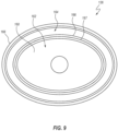
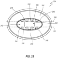
- FIG. 15 is a proximally directed cross-sectional view of the assembled valve 110, which depicts portions of the proximal housing member 124 and the distal housing member 126 at a position just above the septum.
- An oval-shaped sealing region inner limit 180 depicted in broken lines, identifies an inner edge of a region of pressure provided by the sealing rim 167 of the distal housing member 126 (see FIGS. 14 and 16 ). That is, as can be seen in FIG. 14 , the sealing rim 167 presses the septum 122 against the distal face 141 of the sidewall 140 of the proximal housing member 124 to form the first and second (proximal and distal) seals, as previously discussed, and the sealing region inner limit 180 shown in FIG. 15 represents the inner limit of the proximal seal.
- the portion of the septum 122 along which the proximal and distal seals are formed can correspond to an immobilized region of the septum 122. That is, the compressive grip provided by the proximal and distal housing members 124, 126 can provide seals between the housing members 124, 126 and the septum 122 and can also substantially fix a thin region of the septum 122 along a fully periphery of the septum 122.
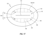
- This sealing and immobilization region can demarcate an outer edge of an active region 182 of the septum 122 (see FIG. 17 ), or stated otherwise, can serve as a fixed outer boundary 184 to a portion of the septum 122 that is permitted to move in at least one direction (i.e., distally and, in some areas, proximally as well).
- the sealing region inner limit 180 previously identified can have an identical or substantially identical footprint to that of the sealing rim 167-for example, an inner periphery of the sealing region inner limit 180 may correspond to an inner edge of the sealing rim 167 (see FIG. 16 ). This inner periphery of the sealing region can correspond to an outer perimeter 184 of the active region 182 of the septum body 170 (see FIG. 17 ), as discussed further below. Note that the septum 122 is not shown in either FIG. 15 or 16 , but is instead shown and discussed with respect to FIG. 17 .
- the distal ends of the fins 144 are also shown. As previously discussed, these distal ends correspond to the restriction surfaces 146, which interact with the septum 122 to inhibit, restrict, delimit, or prevent proximal movement of specific regions of the septum 122. As previously mentioned, in many instances, only a small portion of the restriction surfaces 146 (e.g., the linear regions 147, which are oriented vertically in the present view) interact with-e.g., contact to resist or oppose proximal movement of-the septum 122. In some instances, the septum 122 may contact greater portions of the restriction surfaces 146 due to pressure-induced deformation during aspiration.
- the inner edge of the rim 167 of the distal housing member 126 is shown. As previously discussed the illustrated embodiment, this inner edge can correspond to the sealing region inner limit 180 and the outer peripheral limit or outer perimeter 184 of the active region 182 of the septum body 170 (see FIG. 17 ).
- FIG. 17 is a top plan view of the septum 122, with the outer perimeter 184 of the active region 182 shown as a broken line.
- the outer perimeter 184 of the active region 182 can correspond to the inner edges of the sealing regions that result from clamping the septum 122 between the proximal and distal housing members 124, 126.
- the outer perimeter 184 of the active region 182 is shown in a first style of broken lines.
- FIG. 17 also depicts contact regions 186 at which the septum 122 contacts the restriction surfaces 146 of the fins 144.
- the contact regions 186 are shown in a second style of broken lines. Most of the contact regions 186 are substantially rectilinear and are oriented orthogonally relative to a major axis of the septum 122, which major axis is aligned with the slit 175 in the illustrated embodiment.
- Four substantially triangular contact regions 186 are also present: one at each end of the two rows of substantially rectilinear contact regions 186.
- the outer perimeter 184 of the active region 182 can substantially correspond with an inner perimeter defined by the sidewall 160, and in particular, an inner perimeter defined by the septum support 166 portion of the sidewall 160.
- the outer perimeter 184 is substantially oval.
- the outer perimeter 184 may be said to define a continuously curved shape.
- the active region 182 can further include an inner perimeter 194 that is at least partially defined (i.e., at its rounded ends) by the septum support 166, and is otherwise bounded by the restricted regions 191, 192.
- the restricted regions 191, 192 provide substantially rectilinear boundaries to the inner perimeter 194.
- the inner perimeter 194 is thus substantially shaped as a stadium in the illustrated embodiment, with rectilinear sides and rounded opposing ends.
- the portion of the active region 182 that is interior to the inner perimeter 194 may be termed as a secondary active region 196.
- the full active region 182 may also be referred to as the primary active region 182.
- the septum 122 can bend or pivot along the various boundaries just described-specifically, the outer perimeter 184 and the inner perimeter 194. For example, in some embodiments, during an infusion event, distal movement of the full active region 182 can be unopposed, and the septum 122 may thus bend or pivot distally along the outer perimeter 184. Similarly, during an aspiration event, proximal movement of the restricted regions 191, 192 can be opposed by the fins 144, such that only the secondary active region 196 may move unopposed in the proximal direction. In such instances, the septum 122 may bend or pivot proximally along the inner perimeter 194.
- an entirety of the active region 182 is capable of moving in the distal direction unopposed by any portion of the fins 144. That is, both the secondary active region 196 and the restricted regions 191, 192 of the septum 122 can move distally without any opposition from the fins 144. However, the restricted regions 191, 192 of the septum 122 are inhibited from proximal movement by the fins 144 in manners such as previously discussed. As a result, a greater portion of the septum 122 is permitted to move in the proximal direction or stated otherwise, fluid pressure can act, unopposed, on a greater portion of the septum 122.
- the slit 175 can open at a lower pressure differential, or cracking pressure, in the distal or ingress direction than it does in the proximal or egress direction.
- the full, oval-shaped primary active region 182 of the septum 122 can be acted on and urged distally such that a lower cracking pressure of the slit 175 can be achieved, as compared with an aspiration event, in which only the stadium-shaped, smaller, secondary active region 196 can be acted on unopposed by the fins 144 such that the slit 175 is more difficult to open in the proximal direction and such that a higher cracking pressure of the slit 175 is exhibited.
- the fins 144 permit free movement of the septum 122, including the restricted portion 190 of the septum 122, in the distal or ingress direction; and oppose or inhibit movement of the septum 122, and in particular the restricted portion 190 of the septum 122, in the proximal or egress direction, thus resulting in a higher cracking pressure of the septum in the proximal or egress direction.
- an area of the primary active region 182 is no less than about 1.25, 1.5, 1.75, 2, 2.5, or 3; is no more than about 1.25, 1.5, 1.75, 2, 2.5, or 3; or is within a range of from about 1.25 to about 1.5, 1.75, 2, 2.5, or 3; from about 1.5 to about 1.75, 2, 2.5, or 3; from about 1.75 to about 2, 2.5, or 3; from about 2 to about 2.5 or 3; or from about 2.5 to about 3 times greater than an area of the secondary active region 196.
- the cracking pressure in the proximal direction is no less than 3, 4, 5, 6, 7, 8, 9, 10, 11, 12, 13, 14, or 15 times; no greater than 3, 4, 5, 6, 7, 8, 9, 10, 11, 12, 13, 14, or 15 times; within a range of from 3 to 5, 3 to 8, 3 to 10, 3 to 15, 5 to 8, 5 to 10, 5 to 15, 8 to 10, 8 to 15, or 10 to 15 times; or is about 3, 4, 5, 6, 7, 8, 9, 10, 11, 12, 13, 14, or 15 times the cracking pressure in the distal direction.
- the cracking pressure in the distal direction, or the infusion cracking pressure is no less than about 0.1, 0.15, 0.2, 0.25, 0.3, 0.35, 0.4, 0.5, 0.75, 1.0, 1.25, 1.5, 1.75, or 2.0 psig; is no greater than about 0.1, 0.15, 0.2, 0.25, 0.3, 0.35, 0.4, 0.5, 0.75, 1.0, 1.25, 1.5, 1.75, or 2.0 psig; is within a range of from about 0.1, 0.15, 0.2, 0.25, 0.3, 0.35, 0.4, 0.5, 0.75, 1.0, 1.25, 1.5, or 1.75 to about 2.0 psig; is within a range of from about 0.1, 0.15, 0.2, 0.25, 0.3, 0.35, 0.4, 0.5, 0.75, 1.0, 1.25, or 1.5 to about 1.75 psig; is within a range of from about 0.1, 0.15, 0.2, 0.25, 0.3, 0.35, 0.4, 0.5, 0.75,
- the cracking pressure in the proximal direction, or the aspiration cracking pressure is no less than about 1.0, 1.5, 2.0, 2.5, 3, 4, 5, 6, 7, 8, 9, or 10 psig; is no greater than about 1.0, 1.5, 2.0, 2.5, 3, 4, 5, 6, 7, 8, 9, or 10 psig; is within a range of from about 1.0, 1.5, 2.0, 2.5, 3, 4, 5, 6, 7, 8, 9, or 10 psig; is within a range of from about 1.0, 1.5, 2.0, 2.5, 3, 4, 5, 6, 7, 8, or 9 to about 10 psig; is within a range of from about 1.0, 1.5, 2.0, 2.5, 3, 4, 5, 6, 7, or 8 to about 9 psig; is within a range of from about 1.0, 1.5, 2.0, 2.5, 3, 4, 5, 6 or 7 to about 8 psig; is within a range of from about 1.0, 1.5, 2.0, 2.5, 3, or 4 to about 5 psig; or is about 1.0, 1.5, 2.0, 2.5, 3, 4, 5, 6, 7, 8, 9, or 10 psig.
- each of the distal and proximal cracking pressures for a manufacturing lot of valves can fall within a tolerance range of no more than ⁇ 0.1 psi or ⁇ 0.2 psi. In further instances, the same tolerances are possible from one manufacturing lot to the next, even when different lots of septum materials are used. Stated otherwise, the cracking pressures can be relatively unaffected by minor differences material hardness from one lot of manufacturing materials to the next. In various embodiments, the foregoing cracking pressures can be achieved in embodiments of valves for which the septum 122 satisfies the hardness conditions previously described and/or that meets the septum thickness T and/or the support structure separation distance D criteria previous described.
- a small portion of the restriction surfaces 146 it can be advantageous for only a small portion of the restriction surfaces 146 to come into contact with the septum 122, as this can reduce the area in which blood or pathogens could become trapped between the proximal housing member 124 and the septum 122.
- the contact regions 186 of the septum 122 it can be advantageous for the contact regions 186 of the septum 122 to represent only a small portion of the total area of the restricted portion 190 of the septum 122 that is effectively inhibited from proximal movement by the fins 144.
- a collective total area of the contact regions 186 of the septum 122 is no greater than 10, 20, 30, 40, or 50 percent of the area of the restricted portion 190.
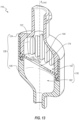
- FIGS. 18-30 depict another embodiment of a bidirectional valve 210 that can resemble embodiments of the valve 110 previously discussed in certain respects. Accordingly, like features are designated with like reference numerals, with the leading digits incremented to "2.” Relevant disclosure set forth above regarding similarly identified features thus may not be repeated hereafter. Moreover, specific features of the valve 210 that correspond to features of the valve 110 may not be shown or identified by a reference numeral in the drawings or specifically discussed in the written description that follows. However, such features may clearly be the same, or substantially the same, as features depicted in other embodiments and/or described with respect to such embodiments. Accordingly, the relevant descriptions of such features apply equally to the features of the system 210 and components thereof.
- valve 110 Any suitable combination of the features and variations of the same described with respect to the valve 110 can be employed with the valve 210, and vice versa.
- This pattern of disclosure applies equally to further embodiments depicted in subsequent figures and described hereafter, wherein the leading digits may be further incremented.
- the valve 210 is shown incorporated into a catheter assembly 200, which can include an additional valve 211.
- the catheter assembly 200 can resemble the catheter assembly 100 in many respects, and can include a catheter shaft 202, a junction 204, a pair of extension legs 206, 207, and a pair of clamps 212, 213.
- the catheter assembly 200 further includes a stylet 209 that extends through the valve 210, the extension leg 206, the junction 204, and a lumen defined by the catheter shaft 202.
- the stylet 209 is prepackaged with the catheter assembly 200 in the depicted orientation.
- a user may insert the stylet 209 as shown prior to using the assembly 200.
- Use of the stylet for insertion and/or positioning of the catheter shaft 202 within the vasculature of the patient can proceed in any suitable manner, including those known in the art.
- the stylet 209 may be omitted.
- the valve 210 can include a housing 220 and a septum 222.
- the housing 220 may include proximal and distal housing members 224, 226 that are fixedly secured to each other in any suitable manner.
- the housing members 224, 226 can be fixedly secured to the septum 222, as discussed further below.
- the proximal housing member 224 can include a connection interface 230 that is configured to couple with one or more medical devices for infusion through the valve 210 in the ingress direction or for aspiration through the valve 210 in the egress direction.
- the connection interface 230 comprises a Luer fitting 232.
- the distal housing member 226 can similarly include a connection interface 234.
- the connection interface 234 comprises a protrusion or port 236 that is configured to be fixedly secured to a proximal end of an extension tube in any suitable manner, and generally in a fluid-tight manner.
- the distal housing member 226 can be overmolded onto an extension leg 206, 207. Other forms of attachment are also contemplated.
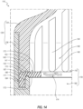
- the proximal housing member 224 can include a sidewall 240 that defines a proximal chamber 242.
- the sidewall 240 can terminate at a distal face 241.
- a sealing rim or gripping rim 243 is positioned at an interior edge of the sidewall 240 and extends distally relative to the sidewall 240.
- the gripping rim 243 can cooperate with the septum 222 to generate proximal and distal seals and can assist in gripping the septum 222 to inhibit or prevent ingestion of the septum 222 in manners similar to those discussed above with respect to the sealing or gripping rim 167.
- the proximal housing member 224 can further include a plurality of support structures 244 that extend inwardly away from the sidewall 240 into the proximal chamber 242.
- Each fin 244 defines a contact or restriction surface 246 at a distal end thereof.
- each pair or adjacent fins 244 defines a fluid channel 248 therebetween.
- the illustrated embodiment includes eight total fins 244, which are arranged in two symmetrical groups of four fins 244 mirrored across a longitudinal plane through the proximal housing member 224 (i.e., the plane of the cross-section of FIG. 22 ).
- each restriction surface 246 extends to and touches a lateral plane 253.
- the gripping rim 243 projects distally past this plane 243.
- each restriction surface 246 extends inwardly from the sidewall 240 and terminates at one of two longitudinal planes 250, 251.
- the fins 244 likewise each terminate at an interior end thereof at a planner surface, which is coplanar with one of two longitudinal planes 250, 251.
- the planes 250, 251 each extend through a proximal opening 252.
- This arrangement can be relatively more compact than the more spaced-apart arrangement of the proximal housing member 124 depicted in FIG. 6 .
- the fins 244 extend into a flow path of fluid that enters into the valve 210 through the proximal opening 252.
- angled surfaces or ramps 255 can be positioned at upper ends of one or more of the fins 244 to reduce or avoid disruption of the fluid flow, such as the formation of turbulence, eddies, etc.
- the distal housing member 226 includes a sidewall 260 that defines a distal chamber 262.
- the distal housing member 226 further includes a plurality of retention members, anchors, or posts 269 that extend proximally from a proximal surface 261 of the sidewall 260.
- the illustrated embodiment includes six posts 269.
- the posts 269 are shaped substantially as frustocones, although other shapes and configurations are contemplated (e.g., cylindrical).
- the frustoconical shape can assist in an assembly process, as the shape can facilitate placement of the septum 222 onto the posts, as further discussed below.
- the posts 269 are regularly spaced about a full periphery of the distal chamber 262.
- the distal housing member 226 includes an outer sleeve 268 that can be positioned over and coupled with the proximal housing member 224. Any suitable attachment mechanism is contemplated, and is desirably fluid tight.
- the outer sleeve 268 can be adhered or solvent bonded to the proximal housing member 224, and in further embodiments, the connection thus achieved can be fluid-tight, even at elevated pressures associated with power injections.
- the outer sleeve 268 includes a groove 265 which, in cooperation with the proximal housing member 224, can define a port or solvent vent 290, as shown in FIG. 29 .
- the groove 265 and the solvent vent 290 extend about a full periphery of the assembled valve 210.
- an appropriate solvent can be provided to an outer surface of the sidewall 240 of the proximal housing member 224 and/or an inner surface of the outer sleeve 268 of the distal housing member 264. As the housing members 224, 264 are subsequently advanced together, liquified portions of these members may be forced into at least a portion of the vent 290.
- the vent 290 may provide an egress port the which the solvent can evaporate.
- the distal housing member 226 defines the groove 265.
- the proximal housing member 224 may additionally or alternatively define the groove.
- the protrusion 236 can be attached to the proximal end of an extension leg in any suitable manner, as previously mentioned.
- the protrusion 236 defines a lumen that receives the extension leg, and an opening at the proximal end of the lumen can, in some instances, be sized to be substantially identical to an inner diameter of the extension leg.
- FIGS. 26 and 27 depict an embodiment of the septum 222, which includes a main septum body 270 and a closure 274.
- the septum 222 further includes a plurality of openings, apertures, or channels 279 that fully extend through the body 270.
- the channels 279 can extend about a periphery of the septum 222.
- the septum 222 includes six channels that are regularly spaced around a periphery thereof. Other arrangements and orientations are contemplated.
- the channels 279 can be formed in any suitable manner. In some embodiments, the channels 279 are cut or stamped from the body 270. In other embodiments, the septum 222 is molded to include the channels 279.
- the septum 222 defines a uniform thickness T 2 .
- the septum 222 is devoid of peripheral flanges, such as discussed above with respect to the septum 122.
- the posts 269 can cooperate with the channels 279 to secure the septum 222 relative to the housing. Stated otherwise, the posts 269 can prevent the septum 222 from being pulled fully into either of the chambers 242, 262 during aspiration or infusion, respectively, or stated otherwise, under the influence of pressurized fluid.
- the proximal housing member 226 can define the posts 269.
- each of the housing members 224, 226 can define one or more of the posts 269, such that some posts may project proximally while others may project distally.
- Such an arrangement could be advantageous from the perspective of tolerancing.
- one housing member 224, 226 may include a post, and the opposing housing member 224, 226 can include a recess or a channel into which the post is receive.
- the gripping rim 243 can impinge upon, embed in, or otherwise grip the septum 222, which opposition forces being provided by the opposing face 261 of the distal housing member 226.
- the gripping rim 243 can form the proximal and distal seals, as previously discussed, and can assist in preventing the septum 222 from being ingested into either of the chambers 242, 262.
- the posts 269 can function as standoffs to ensure a desired spacing between the gripping rim 243 and the proximal face 261 is maintained. Stated otherwise, the posts 262 can prevent the housing members 224, 226 from being over-approximated to each other during manufacture. This can prevent over-compression of the septum 222, which could result in weakening, cutting, or tearing of the septum.
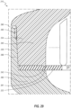
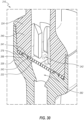
- FIGS. 31 and 32 depict proximal and distal housing members 324, 326, respectively, of another embodiment of a bi-directional valve 310 (see FIG. 35 ).
- the proximal housing member 324 can include a sidewall 340 that defines a distal face 341 at an end thereof.
- the proximal housing member 324 can further define a groove 349 and a gripping rim 343.
- the gripping rim 343 is shaped, in cross-section, substantially as an elongated trapezoid.
- the distal housing member 326 can include a groove 364 and a gripping rim 367.
- the gripping rim 367 is shaped, in cross-section, substantially as an elongated trapezoid.
- the distal housing member 326 can further include a standoff or ledge 361, which extends about a full periphery of the housing member 326 in the illustrated embodiment.
- the ledge 361 can be discontinuous, or stated otherwise, a plurality of standoffs (e.g., ledges) may be distributed around the periphery of the housing member 326.
- a septum 322 includes a main body 370 through which a selectively openable and closable, or sealable, closure 374 extends.
- the septum 322 includes a flange 371 that extends distally from the body 370.
- the septum 322 further includes a second flange 379 that extends proximally from the body 370.
- the flanges 371, 379 may alternatively be considered as a single flange that extends about the full periphery of the body 370 in both the proximal and distal directions.
- the septum 322 can be captured between the proximal and distal housing members 324, 326 and thereby secured to the housing member 324, 326.
- the proximal and distal gripping rims 343, 367 are aligned with each other and impinge on the body 370 of the septum 322 in opposite directions so as to squeeze the septum 322 therebetween.
- the proximal flange 379 of the septum 322 is received within the groove 349 and the distal flange 371 of the septum 322 is received within the groove 364.
- the flanges 379, 371 and the grooves 349, 364 can cooperate with each other to prevent ingestion of the septum 322 during aspiration or infusion.
- the flanges 379, 371 can abut against the outer surfaces of the gripping rims 343, 367, respectively.
- the gap between the gripping rims 343, 367 can be sufficiently small the prevent the flanges 379, 371 from passing therethrough, even when the septum 322 is stretched and/or distorted under the influence of pressurized fluids flowing through the septum 322.
- FIGS. 36 and 37 depict an embodiment of a projection plate 405 that can be incorporated into certain embodiments of bi-directional valves.
- the projection plate 405 can be incorporated into embodiments of the valves 110, 210, 310.
- the projection plate 405 can comprise a body 480 from which a plurality of projections 444 extend inwardly into an opening 407.
- the opening 407 can extend fully through the body 480.
- the projections 444 can define a profile similar to the plan-view profile of other embodiments.
- the projection plate 405 can have a similar profile to the bottom plan view of the proximal housing member 224, as depicted in FIG. 23 .
- the projections 444 can replace other projection features previously disclosed.
- the fins 244 of the proximal housing member 224 e.g., of FIGS. 21-23
- the projection plate 405 can instead be incorporated into the valve 210 by being placed between the proximal surface of the septum 222 and the distal face 241 of the proximal housing member 224.
- the illustrated fins can be omitted and replaced with the projection plate 405.
- the projections 444 can function substantially in the same manner as the bottom ends of the fins, as previously disclosed.
- the plate 405 can be securely attached to the proximal housing member in an early stage of assembly-e.g., prior to coupling the proximal housing member to the septum and the distal housing member.
- the projection plate 405 defines a thickness T 3 .
- composition of the projection plate 405 and/or the thickness T 3 may be sufficient to prevent or inhibit the projections 444 from bending, either distally or proximally, during infusion or aspiration, respectively.
- the projection plate 405 includes one or more of metallic or polymeric materials.
- the projection plate 405 is formed of a sheet metal, such as a sheet of stainless steel.
- the projection plate 405 comprises a metalized plastic (e.g., a plastic sheet coated in metal). In some instances, inclusion of a metallic material may provide advantageous antimicrobial properties.
- the tips of the projections 444 have a rectangular profile. In other embodiments, the tips of one or more of the projections 444 may have a rounded or smooth profile. In some embodiments, all edges of the projection plate may be smoothed.
- Any methods disclosed herein comprise one or more steps or actions for performing the described method.
- the method steps and/or actions may be interchanged with one another.
- the order and/or use of specific steps and/or actions may be modified.
- the valve may be operated with the valve in any orientation (e.g., independent of whether the Luer fitting is “up” or “down” relative to a gravitational influences).
- the term “coupled,” as used herein, is defined as directly or indirectly connected in any suitable manner. Objects described herein as being “adjacent to” each other may be in physical contact with each other, in close proximity to each other, or in the same general region or area as each other, as appropriate for the context in which the phrase is used. Occurrences of the phrase “in one embodiment,” or “in one aspect,” herein do not necessarily all refer to the same embodiment or aspect.
- the term “substantially” refers to the complete or nearly-complete extent or degree of an action, characteristic, property, state, structure, item, or result.
- an object that is “substantially” enclosed would mean that the object is either completely enclosed or nearly completely enclosed.
- the exact allowable degree of deviation from absolute completeness may in some cases depend on the specific context. However, generally speaking the nearness of completion will be so as to have the same overall result as if absolute and total completion were obtained.
- the use of “substantially” is equally applicable when used in a negative connotation to refer to the complete or near complete lack of an action, characteristic, property, state, structure, item, or result.
- compositions that is "substantially free of” particles would either completely lack particles, or so nearly completely lack particles that the effect would be the same as if it completely lacked particles.
- a composition that is "substantially free of” an ingredient or element may still actually contain such item as long as there is no measurable effect thereof.
- the term “about” is used to provide flexibility to a numerical range endpoint by providing that a given value may be “a little above” or “a little below” the endpoint.
- references to approximations such as by use of the terms “about” or “approximately,” or other terms, it is to be understood that, in some embodiments, the value, feature, or characteristic may be specified without approximation.
- qualifiers such as “about,” “substantially,” and “generally” are used, these terms include within their scope the qualified words in the absence of their qualifiers.
- the term “substantially perpendicular” is recited with respect to a feature, it is understood that in further embodiments, the feature can have a precisely perpendicular orientation.
Landscapes
- Health & Medical Sciences (AREA)
- Life Sciences & Earth Sciences (AREA)
- Heart & Thoracic Surgery (AREA)
- Engineering & Computer Science (AREA)
- Public Health (AREA)
- Biomedical Technology (AREA)
- Hematology (AREA)
- Animal Behavior & Ethology (AREA)
- General Health & Medical Sciences (AREA)
- Veterinary Medicine (AREA)
- Anesthesiology (AREA)
- Pulmonology (AREA)
- Biophysics (AREA)
- Physics & Mathematics (AREA)
- Pathology (AREA)
- Medical Informatics (AREA)
- Molecular Biology (AREA)
- Surgery (AREA)
- Gastroenterology & Hepatology (AREA)
- Manufacturing & Machinery (AREA)
- Infusion, Injection, And Reservoir Apparatuses (AREA)
Claims (15)
- Medizinisches Ventil (110, 111, 210, 211, 310), umfassend:ein Gehäuse (120, 220), das eine Seitenwand (140, 240, 340) umfasst und eine Kammer (178) definiert;eine Verbindungsschnittstelle (130, 230) in Fluidkommunikation mit der Kammer (178), wobei die Verbindungsschnittstelle (130, 230) dazu konfiguriert ist, mit einem oder mehreren medizinischen Geräten gekoppelt zu werden, um Fluid durch das medizinische Ventil (110, 111, 210, 211, 310) in einer distalen Richtung zu infundieren und Fluid durch das medizinische Ventil (110, 111, 210, 211, 310) in einer proximalen Richtung abzusaugen;ein Septum (122, 222, 322), das mit dem Gehäuse (120, 220) gekoppelt ist, wobei das Septum (122, 222, 322) eine proximale Oberfläche, eine distale Oberfläche und einen selektiv zu öffnenden Verschluss (174, 274, 374) umfasst, der sich durch eine volle Dicke des Septums (122, 222, 322) zwischen der proximalen Oberfläche und der distalen Oberfläche erstreckt, wobei der Verschluss (174, 274, 374) innerhalb der Kammer (178) positioniert ist; undeine Vielzahl von Vorsprüngen (144, 244, 444), die sich von der Seitenwand (140, 240, 340) weg erstrecken, wobei jeder Vorsprung (144, 244, 444) an einem distalen Ende davon eine Begrenzungsoberfläche (146, 246) umfasst, die dazu konfiguriert ist, die proximale Oberfläche des Septums (122, 222, 322) zu berühren, um einer Bewegung eines begrenzten Abschnitts (190) des Septums (122, 222, 322) in der proximalen Richtung so entgegenzuwirken, dass ein zum Öffnen des Verschlusses (174, 274, 374) erforderlicher Aspirationsöffnungsdruck, um einen Fluidfluss durch das Septum (122, 222, 322) in der proximalen Richtung zu ermöglichen, einen zum Öffnen des Verschlusses (174, 274, 374) erforderlichen Infusionsöffnungsdruck, um einen Fluidfluss durch das Septum (122, 222, 322) in der distalen Richtung zu ermöglichen, übersteigt,wobei das Septum (122, 222, 322) ferner Berührungsbereiche (186) umfasst, an denen das Septum (122, 222, 322) die Begrenzungsoberflächen (146, 246) der Vielzahl von Vorsprüngen (144, 244, 444) berührt, wobei die Berührungsbereiche (186) den begrenzten Abschnitt (190) des Septums (122, 222, 322) definieren und eine gemeinsame Gesamtfläche aufweisen, die nur einen Abschnitt einer Gesamtfläche des begrenzten Abschnitts (190) des Septums (122, 222, 322) darstellt.
- Medizinisches Ventil (110, 111, 210, 211, 310) nach Anspruch 1, wobei die Vielzahl von Vorsprüngen (144, 244, 444) dazu konfiguriert ist, eine freie Bewegung des begrenzten Abschnitts (190) des Septums (122, 222, 322) in der distalen Richtung zu ermöglichen.
- Medizinisches Ventil (110, 111, 210, 211, 310) nach Anspruch 1 oder 2, wobei die Vielzahl von Vorsprüngen (144, 244, 444) in zwei unterschiedlichen Gruppen angeordnet ist, die an gegenüberliegenden Seiten des Verschlusses (174, 274, 374) positioniert sind, wobei jede Gruppe mehrere Vorsprünge (144, 244, 444) beinhaltet.
- Medizinisches Ventil (110, 111, 210, 211, 310) nach Anspruch 1, wobei die gemeinsame Gesamtfläche der Berührungsbereiche (186) des Septums (122, 222, 322) nicht größer ist als 50 Prozent der Gesamtfläche des begrenzten Abschnitts (190) des Septums (122, 222, 322), optional wobei die gemeinsame Gesamtfläche der Berührungsbereiche (186) des Septums (122, 222, 322) nicht größer ist als 40 Prozent der Gesamtfläche des begrenzten Abschnitts (190) des Septums (122, 222, 322), optional wobei die gemeinsame Gesamtfläche der Berührungsbereiche (186) des Septums (122, 222, 322) nicht größer ist als 30 Prozent der Gesamtfläche des begrenzten Abschnitts (190) des Septums (122, 222, 322), optional wobei die gemeinsame Gesamtfläche der Berührungsbereiche (186) des Septums (122, 222, 322) nicht größer ist als 20 Prozent der Gesamtfläche des begrenzten Abschnitts (190) des Septums (122, 222, 322), optional wobei die gemeinsame Gesamtfläche der Berührungsbereiche (186) des Septums (122, 222, 322) nicht größer ist als 10 Prozent der Gesamtfläche des begrenzten Abschnitts (190) des Septums (122, 222, 322).
- Medizinisches Ventil (110, 111, 210, 211, 310) nach Anspruch 1, wobei jede Begrenzungsoberfläche (146, 246) von zumindest einigen der Vielzahl von Vorsprüngen (144, 244, 444):eine gekrümmte Oberfläche an einem distalen Ende davon beinhaltet;eine abgerundete Oberfläche an einem distalen Ende davon beinhaltet;als Halbzylinder gestaltet ist;einen halbkreisförmigen Querschnitt definiert;einen U-förmigen Querschnitt definiert;aus zwei ebenen Flächen gebildet ist, die sich an einer Linie treffen, die sich entlang einer Unterkante der Begrenzungsoberfläche (146, 246) erstreckt,im Querschnitt V-förmig ist;ein distales Ende aufweist, das eine gerade Linie definiert;konvex gekrümmt ist; oderkonvex gerundet ist.
- Medizinisches Ventil (110, 111, 210, 211, 310) nach Anspruch 1, wobei die Seitenwand (140, 240, 340) des Gehäuses (120, 220) einen äußeren Umfang (184) eines primären aktiven Bereichs (182) des Septums (122, 222, 322) definiert, wobei der begrenzte Abschnitt (190) des Septums (122, 222, 322) und die Seitenwand (140, 240, 340) zusammenwirken, um einen Umfang (194) eines sekundären aktiven Bereichs (196) des Septums (122, 222, 322) zu definieren, und wobei der primäre aktive Bereich (182) des Septums (122, 222, 322) größer ist als der sekundäre aktive Bereich (196).
- Medizinisches Ventil (110, 111, 210, 211, 310) nach Anspruch 1, wobei Paare benachbarter Vorsprünge (144, 244, 444) Spülkanäle (148, 248) definieren, durch die ein Fluid fließen kann, um die Begrenzungsoberflächen (146, 246) der Vorsprünge (144, 244, 444) zu spülen, wenn das Fluid das medizinische Ventil (110, 111, 210, 211, 310) in der distalen Richtung durchfließt.
- Medizinisches Ventil (110, 111, 210, 211, 310) nach Anspruch 7, wobei das medizinische Ventil (110, 111, 210, 211, 310) eine Längsachse definiert, die im Allgemeinen einer Fluidflussrichtung durch das medizinische Ventil (110, 111, 210, 211, 310) entspricht, und wobei die Spülkanäle (148, 248) im Wesentlichen parallel zur Längsachse ausgerichtet sind.
- Medizinisches Ventil (110, 111, 210, 211, 310) nach Anspruch 1, wobei die Vielzahl von Vorsprüngen (144, 244, 444) dazu konfiguriert ist, einer Bewegung des begrenzten Abschnitts (190) des Septums (122, 222, 322) in der distalen Richtung nicht entgegenzuwirken.
- Medizinisches Ventil (110, 111, 210, 211, 310) nach Anspruch 1, wobei das Septum (122, 222, 322) ausreichend nachgiebig ist, um sich in der distalen Richtung ausreichend weit von der Vielzahl von Vorsprüngen (144, 244, 444) wegzubewegen, um den Durchfluss von Fluid zwischen der Vielzahl von Vorsprüngen (144, 244, 444) und dem Septum (122, 222, 322) so zu ermöglichen, dass während der Infusion von Fluid durch das Ventil in der distalen Richtung im Wesentlichen die gesamte proximale Oberfläche des Septums (122, 222, 322) gespült wird.
- Medizinisches Ventil (110, 111, 210, 211, 310) nach Anspruch 1, wobei das Gehäuse (120, 220) zwei separate Gehäuseelemente (124, 126, 224, 226, 324, 326) umfasst, die miteinander verbunden sind, und wobei die Vorsprünge (144, 244, 444) nur mit einem der beiden Gehäuseelemente (124, 126, 224, 226, 324, 326) gekoppelt sind.
- Medizinisches Ventil (110, 111, 210, 211, 310) nach Anspruch 1, wobei die Vielzahl von Vorsprüngen (144, 244, 444) eine Vielzahl von Lamellen umfasst.
- Medizinisches Ventil (110, 111, 210, 211, 310) nach Anspruch 12, wobei sich jede Lamelle der Vielzahl von Lamellen in Längsrichtung erstreckt, optional wobei jede Lamelle eine im Wesentlichen ebene Fläche umfasst, die sich in Längsrichtung erstreckt und an einem distalen Ende davon mit einem abgerundeten Ende verbunden ist, das dem Septum (122, 222, 322) zugewandt ist, optional wobei jedes Paar benachbarter Lamellen einen Fluidkanal dazwischen definiert, der dazu konfiguriert ist, einen Fluidfluss in Längsrichtung entlang der Oberfläche der Lamellen zu fördern und die Spülung an den distalen Enden der Lamellen zu verbessern.
- Medizinisches Ventil (110, 111, 210, 211, 310) nach Anspruch 1, ferner umfassend eine Platte (405), die die Vorsprünge (144, 244, 444) definiert, optional wobei die Platte (405) eine separate Komponente umfasst, die an dem Gehäuse (120, 220) befestigt ist, optional wobei die Platte (405) ein Metallblech umfasst.
- Katheteranordnung (100, 200), umfassend:einen Katheter (102, 202); unddas medizinische Ventil (110, 111, 210, 211, 310) nach einem der vorhergehenden Ansprüche, das mit dem Katheter (102, 202) gekoppelt ist.
Applications Claiming Priority (2)
| Application Number | Priority Date | Filing Date | Title |
|---|---|---|---|
| US201862771375P | 2018-11-26 | 2018-11-26 | |
| PCT/US2019/063466 WO2020112915A1 (en) | 2018-11-26 | 2019-11-26 | Bidirectional medical valves |
Publications (4)
| Publication Number | Publication Date |
|---|---|
| EP3886973A1 EP3886973A1 (de) | 2021-10-06 |
| EP3886973A4 EP3886973A4 (de) | 2022-11-30 |
| EP3886973B1 true EP3886973B1 (de) | 2024-09-25 |
| EP3886973C0 EP3886973C0 (de) | 2024-09-25 |
Family
ID=70851872
Family Applications (1)
| Application Number | Title | Priority Date | Filing Date |
|---|---|---|---|
| EP19890202.5A Active EP3886973B1 (de) | 2018-11-26 | 2019-11-26 | Bidirektionale medizinische ventile |
Country Status (4)
| Country | Link |
|---|---|
| US (1) | US11684765B2 (de) |
| EP (1) | EP3886973B1 (de) |
| BR (1) | BR112021010724A2 (de) |
| WO (1) | WO2020112915A1 (de) |
Families Citing this family (5)
| Publication number | Priority date | Publication date | Assignee | Title |
|---|---|---|---|---|
| EP3886973B1 (de) | 2018-11-26 | 2024-09-25 | Piper Access, LLC | Bidirektionale medizinische ventile |
| US11560953B2 (en) * | 2020-06-30 | 2023-01-24 | Illinois Tool Works Inc. | Anti-free-flow valve |
| DE102020209931A1 (de) * | 2020-08-06 | 2022-02-10 | B. Braun Melsungen Aktiengesellschaft | Katheteranordnung |
| EP4450118A4 (de) * | 2021-12-28 | 2025-10-22 | Nikkiso Co Ltd | Zugangsöffnungselement und herstellungsverfahren dafür |
| USD1052047S1 (en) | 2022-02-11 | 2024-11-19 | Joseph Richard Cant | Valve for a nozzle |
Family Cites Families (17)
| Publication number | Priority date | Publication date | Assignee | Title |
|---|---|---|---|---|
| US4143853A (en) * | 1977-07-14 | 1979-03-13 | Metatech Corporation | Valve for use with a catheter or the like |
| US4354492A (en) * | 1979-04-16 | 1982-10-19 | American Hospital Supply Corporation | Medical administration set with backflow check valve |
| US4946448A (en) | 1989-10-23 | 1990-08-07 | Kendall Mcgaw Laboratories, Inc. | Check valve for use with intravenous pump |
| US5201722A (en) | 1990-09-04 | 1993-04-13 | Moorehead Robert H | Two-way outdwelling slit valving of medical liquid flow through a cannula and methods |
| US5205834A (en) | 1990-09-04 | 1993-04-27 | Moorehead H Robert | Two-way outdwelling slit valving of medical liquid flow through a cannula and methods |
| DE4127628C1 (de) | 1991-08-21 | 1992-07-23 | Vygon Gmbh & Co Kg, 5100 Aachen, De | |
| US5957898A (en) * | 1997-05-20 | 1999-09-28 | Baxter International Inc. | Needleless connector |
| US7601141B2 (en) | 2002-11-26 | 2009-10-13 | Nexus Medical, Llc | Pressure actuated flow control valve |
| US7252652B2 (en) * | 2003-08-29 | 2007-08-07 | Boston Scientific Scimed, Inc. | Valved catheters including high flow rate catheters |
| US7673653B2 (en) | 2004-06-17 | 2010-03-09 | Filtertek Inc. | Check valve |
| US8123726B2 (en) * | 2009-06-09 | 2012-02-28 | Oscor Inc. | Low insertion force hemostasis valve for vascular introducer |
| US20110087093A1 (en) | 2009-10-09 | 2011-04-14 | Navilyst Medical, Inc. | Valve configurations for implantable medical devices |
| USD644731S1 (en) | 2010-03-23 | 2011-09-06 | Icu Medical, Inc. | Medical connector |
| CN105120943B (zh) * | 2013-03-16 | 2018-02-13 | 宝利麦迪柯尔有限公司 | 输送装置的阀 |
| US9901676B2 (en) * | 2013-06-17 | 2018-02-27 | Illinois Tool Works Inc. | Bidirectional valve with improved threshold pressure accuracy |
| US10610678B2 (en) | 2016-08-11 | 2020-04-07 | Angiodynamics, Inc. | Bi-directional, pressure-actuated medical valve with improved fluid flow control and method of using such |
| EP3886973B1 (de) | 2018-11-26 | 2024-09-25 | Piper Access, LLC | Bidirektionale medizinische ventile |
-
2019
- 2019-11-26 EP EP19890202.5A patent/EP3886973B1/de active Active
- 2019-11-26 BR BR112021010724-0A patent/BR112021010724A2/pt not_active Application Discontinuation
- 2019-11-26 US US16/697,156 patent/US11684765B2/en active Active
- 2019-11-26 WO PCT/US2019/063466 patent/WO2020112915A1/en not_active Ceased
Also Published As
| Publication number | Publication date |
|---|---|
| US20200197683A1 (en) | 2020-06-25 |
| EP3886973A1 (de) | 2021-10-06 |
| BR112021010724A2 (pt) | 2021-08-31 |
| WO2020112915A1 (en) | 2020-06-04 |
| EP3886973A4 (de) | 2022-11-30 |
| US11684765B2 (en) | 2023-06-27 |
| EP3886973C0 (de) | 2024-09-25 |
Similar Documents
| Publication | Publication Date | Title |
|---|---|---|
| EP3886973B1 (de) | Bidirektionale medizinische ventile | |
| US12194249B2 (en) | Multiple-use intravenous catheter assembly septum and septum actuator | |
| RU2742869C2 (ru) | Внутривенный катетер с функцией безопасности и клапанным элементом, управляемым давлением | |
| US9138572B2 (en) | Medical valve with fluid volume alteration | |
| US20100249725A1 (en) | Medical Valve with Multiple Variable Volume Regions | |
| CN105396212A (zh) | 带阀导管组件和相关方法 | |
| US12239814B2 (en) | Methods and devices for vascular access | |
| KR102834133B1 (ko) | 카테터 프라이밍 디바이스, 시스템 및 방법 | |
| US10413712B1 (en) | Luer-activated valves | |
| WO2022178506A1 (en) | Methods and devices for vascular access | |
| CN114796712A (zh) | 阀固定环及相关系统和方法 | |
| US20250281732A1 (en) | Methods and devices for vascular access | |
| CN117045248A (zh) | 流动限制装置 |
Legal Events
| Date | Code | Title | Description |
|---|---|---|---|
| STAA | Information on the status of an ep patent application or granted ep patent |
Free format text: STATUS: THE INTERNATIONAL PUBLICATION HAS BEEN MADE |
|
| PUAI | Public reference made under article 153(3) epc to a published international application that has entered the european phase |
Free format text: ORIGINAL CODE: 0009012 |
|
| STAA | Information on the status of an ep patent application or granted ep patent |
Free format text: STATUS: REQUEST FOR EXAMINATION WAS MADE |
|
| 17P | Request for examination filed |
Effective date: 20210528 |
|
| AK | Designated contracting states |
Kind code of ref document: A1 Designated state(s): AL AT BE BG CH CY CZ DE DK EE ES FI FR GB GR HR HU IE IS IT LI LT LU LV MC MK MT NL NO PL PT RO RS SE SI SK SM TR |
|
| DAV | Request for validation of the european patent (deleted) | ||
| DAX | Request for extension of the european patent (deleted) | ||
| REG | Reference to a national code |
Ref country code: DE Ref legal event code: R079 Free format text: PREVIOUS MAIN CLASS: A61M0039240000 Ipc: A61M0039220000 Ref country code: DE Ref legal event code: R079 Ref document number: 602019059584 Country of ref document: DE Free format text: PREVIOUS MAIN CLASS: A61M0039240000 Ipc: A61M0039220000 |
|
| A4 | Supplementary search report drawn up and despatched |
Effective date: 20221031 |
|
| RIC1 | Information provided on ipc code assigned before grant |
Ipc: A61B 5/15 20060101ALI20221025BHEP Ipc: A61M 39/24 20060101ALI20221025BHEP Ipc: A61M 39/22 20060101AFI20221025BHEP |
|
| GRAP | Despatch of communication of intention to grant a patent |
Free format text: ORIGINAL CODE: EPIDOSNIGR1 |
|
| STAA | Information on the status of an ep patent application or granted ep patent |
Free format text: STATUS: GRANT OF PATENT IS INTENDED |
|
| INTG | Intention to grant announced |
Effective date: 20240405 |
|
| GRAS | Grant fee paid |
Free format text: ORIGINAL CODE: EPIDOSNIGR3 |
|
| GRAA | (expected) grant |
Free format text: ORIGINAL CODE: 0009210 |
|
| STAA | Information on the status of an ep patent application or granted ep patent |
Free format text: STATUS: THE PATENT HAS BEEN GRANTED |
|
| RAP3 | Party data changed (applicant data changed or rights of an application transferred) |
Owner name: PIPER ACCESS, LLC |
|
| AK | Designated contracting states |
Kind code of ref document: B1 Designated state(s): AL AT BE BG CH CY CZ DE DK EE ES FI FR GB GR HR HU IE IS IT LI LT LU LV MC MK MT NL NO PL PT RO RS SE SI SK SM TR |
|
| REG | Reference to a national code |
Ref country code: GB Ref legal event code: FG4D |
|
| REG | Reference to a national code |
Ref country code: CH Ref legal event code: EP |
|
| REG | Reference to a national code |
Ref country code: DE Ref legal event code: R096 Ref document number: 602019059584 Country of ref document: DE |
|
| REG | Reference to a national code |
Ref country code: IE Ref legal event code: FG4D |
|
| U01 | Request for unitary effect filed |
Effective date: 20240930 |
|
| U07 | Unitary effect registered |
Designated state(s): AT BE BG DE DK EE FI FR IT LT LU LV MT NL PT RO SE SI Effective date: 20241018 |
|
| PG25 | Lapsed in a contracting state [announced via postgrant information from national office to epo] |
Ref country code: NO Free format text: LAPSE BECAUSE OF FAILURE TO SUBMIT A TRANSLATION OF THE DESCRIPTION OR TO PAY THE FEE WITHIN THE PRESCRIBED TIME-LIMIT Effective date: 20241225 |
|
| PG25 | Lapsed in a contracting state [announced via postgrant information from national office to epo] |
Ref country code: GR Free format text: LAPSE BECAUSE OF FAILURE TO SUBMIT A TRANSLATION OF THE DESCRIPTION OR TO PAY THE FEE WITHIN THE PRESCRIBED TIME-LIMIT Effective date: 20241226 |
|
| PGFP | Annual fee paid to national office [announced via postgrant information from national office to epo] |
Ref country code: GB Payment date: 20241230 Year of fee payment: 6 |
|
| PG25 | Lapsed in a contracting state [announced via postgrant information from national office to epo] |
Ref country code: RS Free format text: LAPSE BECAUSE OF FAILURE TO SUBMIT A TRANSLATION OF THE DESCRIPTION OR TO PAY THE FEE WITHIN THE PRESCRIBED TIME-LIMIT Effective date: 20241225 |
|
| PG25 | Lapsed in a contracting state [announced via postgrant information from national office to epo] |
Ref country code: RS Free format text: LAPSE BECAUSE OF FAILURE TO SUBMIT A TRANSLATION OF THE DESCRIPTION OR TO PAY THE FEE WITHIN THE PRESCRIBED TIME-LIMIT Effective date: 20241225 Ref country code: NO Free format text: LAPSE BECAUSE OF FAILURE TO SUBMIT A TRANSLATION OF THE DESCRIPTION OR TO PAY THE FEE WITHIN THE PRESCRIBED TIME-LIMIT Effective date: 20241225 Ref country code: GR Free format text: LAPSE BECAUSE OF FAILURE TO SUBMIT A TRANSLATION OF THE DESCRIPTION OR TO PAY THE FEE WITHIN THE PRESCRIBED TIME-LIMIT Effective date: 20241226 |
|
| U20 | Renewal fee for the european patent with unitary effect paid |
Year of fee payment: 6 Effective date: 20241230 |
|
| PG25 | Lapsed in a contracting state [announced via postgrant information from national office to epo] |
Ref country code: IS Free format text: LAPSE BECAUSE OF FAILURE TO SUBMIT A TRANSLATION OF THE DESCRIPTION OR TO PAY THE FEE WITHIN THE PRESCRIBED TIME-LIMIT Effective date: 20250125 |
|
| PG25 | Lapsed in a contracting state [announced via postgrant information from national office to epo] |
Ref country code: SM Free format text: LAPSE BECAUSE OF FAILURE TO SUBMIT A TRANSLATION OF THE DESCRIPTION OR TO PAY THE FEE WITHIN THE PRESCRIBED TIME-LIMIT Effective date: 20240925 |
|
| PG25 | Lapsed in a contracting state [announced via postgrant information from national office to epo] |
Ref country code: ES Free format text: LAPSE BECAUSE OF FAILURE TO SUBMIT A TRANSLATION OF THE DESCRIPTION OR TO PAY THE FEE WITHIN THE PRESCRIBED TIME-LIMIT Effective date: 20240925 |
|
| PG25 | Lapsed in a contracting state [announced via postgrant information from national office to epo] |
Ref country code: PL Free format text: LAPSE BECAUSE OF FAILURE TO SUBMIT A TRANSLATION OF THE DESCRIPTION OR TO PAY THE FEE WITHIN THE PRESCRIBED TIME-LIMIT Effective date: 20240925 Ref country code: CZ Free format text: LAPSE BECAUSE OF FAILURE TO SUBMIT A TRANSLATION OF THE DESCRIPTION OR TO PAY THE FEE WITHIN THE PRESCRIBED TIME-LIMIT Effective date: 20240925 |
|
| PG25 | Lapsed in a contracting state [announced via postgrant information from national office to epo] |
Ref country code: SK Free format text: LAPSE BECAUSE OF FAILURE TO SUBMIT A TRANSLATION OF THE DESCRIPTION OR TO PAY THE FEE WITHIN THE PRESCRIBED TIME-LIMIT Effective date: 20240925 |
|
| REG | Reference to a national code |
Ref country code: CH Ref legal event code: PL |
|
| PG25 | Lapsed in a contracting state [announced via postgrant information from national office to epo] |
Ref country code: MC Free format text: LAPSE BECAUSE OF FAILURE TO SUBMIT A TRANSLATION OF THE DESCRIPTION OR TO PAY THE FEE WITHIN THE PRESCRIBED TIME-LIMIT Effective date: 20240925 |
|
| REG | Reference to a national code |
Ref country code: CH Ref legal event code: PL |
|
| PG25 | Lapsed in a contracting state [announced via postgrant information from national office to epo] |
Ref country code: CH Free format text: LAPSE BECAUSE OF NON-PAYMENT OF DUE FEES Effective date: 20241130 |
|
| PLBE | No opposition filed within time limit |
Free format text: ORIGINAL CODE: 0009261 |
|
| STAA | Information on the status of an ep patent application or granted ep patent |
Free format text: STATUS: NO OPPOSITION FILED WITHIN TIME LIMIT |
|
| 26N | No opposition filed |
Effective date: 20250626 |
|
| PG25 | Lapsed in a contracting state [announced via postgrant information from national office to epo] |
Ref country code: IE Free format text: LAPSE BECAUSE OF NON-PAYMENT OF DUE FEES Effective date: 20241126 |