EP3886140B1 - Gas processing system - Google Patents
Gas processing system Download PDFInfo
- Publication number
- EP3886140B1 EP3886140B1 EP21173775.4A EP21173775A EP3886140B1 EP 3886140 B1 EP3886140 B1 EP 3886140B1 EP 21173775 A EP21173775 A EP 21173775A EP 3886140 B1 EP3886140 B1 EP 3886140B1
- Authority
- EP
- European Patent Office
- Prior art keywords
- waveguide
- plasma
- gas
- microwave radiation
- microwave
- Prior art date
- Legal status (The legal status is an assumption and is not a legal conclusion. Google has not performed a legal analysis and makes no representation as to the accuracy of the status listed.)
- Active
Links
Images





Classifications
-
- H—ELECTRICITY
- H01—ELECTRIC ELEMENTS
- H01J—ELECTRIC DISCHARGE TUBES OR DISCHARGE LAMPS
- H01J37/00—Discharge tubes with provision for introducing objects or material to be exposed to the discharge, e.g. for the purpose of examination or processing thereof
- H01J37/32—Gas-filled discharge tubes
- H01J37/32009—Arrangements for generation of plasma specially adapted for examination or treatment of objects, e.g. plasma sources
- H01J37/32192—Microwave generated discharge
- H01J37/32211—Means for coupling power to the plasma
- H01J37/32229—Waveguides
-
- B—PERFORMING OPERATIONS; TRANSPORTING
- B01—PHYSICAL OR CHEMICAL PROCESSES OR APPARATUS IN GENERAL
- B01J—CHEMICAL OR PHYSICAL PROCESSES, e.g. CATALYSIS OR COLLOID CHEMISTRY; THEIR RELEVANT APPARATUS
- B01J19/00—Chemical, physical or physico-chemical processes in general; Their relevant apparatus
- B01J19/08—Processes employing the direct application of electric or wave energy, or particle radiation; Apparatus therefor
- B01J19/12—Processes employing the direct application of electric or wave energy, or particle radiation; Apparatus therefor employing electromagnetic waves
- B01J19/122—Incoherent waves
- B01J19/126—Microwaves
-
- B—PERFORMING OPERATIONS; TRANSPORTING
- B01—PHYSICAL OR CHEMICAL PROCESSES OR APPARATUS IN GENERAL
- B01D—SEPARATION
- B01D53/00—Separation of gases or vapours; Recovering vapours of volatile solvents from gases; Chemical or biological purification of waste gases, e.g. engine exhaust gases, smoke, fumes, flue gases, aerosols
- B01D53/007—Separation of gases or vapours; Recovering vapours of volatile solvents from gases; Chemical or biological purification of waste gases, e.g. engine exhaust gases, smoke, fumes, flue gases, aerosols by irradiation
-
- B—PERFORMING OPERATIONS; TRANSPORTING
- B01—PHYSICAL OR CHEMICAL PROCESSES OR APPARATUS IN GENERAL
- B01D—SEPARATION
- B01D53/00—Separation of gases or vapours; Recovering vapours of volatile solvents from gases; Chemical or biological purification of waste gases, e.g. engine exhaust gases, smoke, fumes, flue gases, aerosols
- B01D53/32—Separation of gases or vapours; Recovering vapours of volatile solvents from gases; Chemical or biological purification of waste gases, e.g. engine exhaust gases, smoke, fumes, flue gases, aerosols by electrical effects other than those provided for in group B01D61/00
- B01D53/323—Separation of gases or vapours; Recovering vapours of volatile solvents from gases; Chemical or biological purification of waste gases, e.g. engine exhaust gases, smoke, fumes, flue gases, aerosols by electrical effects other than those provided for in group B01D61/00 by electrostatic effects or by high-voltage electric fields
-
- B—PERFORMING OPERATIONS; TRANSPORTING
- B01—PHYSICAL OR CHEMICAL PROCESSES OR APPARATUS IN GENERAL
- B01J—CHEMICAL OR PHYSICAL PROCESSES, e.g. CATALYSIS OR COLLOID CHEMISTRY; THEIR RELEVANT APPARATUS
- B01J19/00—Chemical, physical or physico-chemical processes in general; Their relevant apparatus
- B01J19/08—Processes employing the direct application of electric or wave energy, or particle radiation; Apparatus therefor
- B01J19/087—Processes employing the direct application of electric or wave energy, or particle radiation; Apparatus therefor employing electric or magnetic energy
- B01J19/088—Processes employing the direct application of electric or wave energy, or particle radiation; Apparatus therefor employing electric or magnetic energy giving rise to electric discharges
-
- H—ELECTRICITY
- H01—ELECTRIC ELEMENTS
- H01J—ELECTRIC DISCHARGE TUBES OR DISCHARGE LAMPS
- H01J37/00—Discharge tubes with provision for introducing objects or material to be exposed to the discharge, e.g. for the purpose of examination or processing thereof
- H01J37/32—Gas-filled discharge tubes
- H01J37/32009—Arrangements for generation of plasma specially adapted for examination or treatment of objects, e.g. plasma sources
- H01J37/32192—Microwave generated discharge
- H01J37/32266—Means for controlling power transmitted to the plasma
-
- H—ELECTRICITY
- H01—ELECTRIC ELEMENTS
- H01J—ELECTRIC DISCHARGE TUBES OR DISCHARGE LAMPS
- H01J37/00—Discharge tubes with provision for introducing objects or material to be exposed to the discharge, e.g. for the purpose of examination or processing thereof
- H01J37/32—Gas-filled discharge tubes
- H01J37/32009—Arrangements for generation of plasma specially adapted for examination or treatment of objects, e.g. plasma sources
- H01J37/32192—Microwave generated discharge
- H01J37/32311—Circuits specially adapted for controlling the microwave discharge
-
- H—ELECTRICITY
- H01—ELECTRIC ELEMENTS
- H01J—ELECTRIC DISCHARGE TUBES OR DISCHARGE LAMPS
- H01J37/00—Discharge tubes with provision for introducing objects or material to be exposed to the discharge, e.g. for the purpose of examination or processing thereof
- H01J37/32—Gas-filled discharge tubes
- H01J37/32431—Constructional details of the reactor
- H01J37/3244—Gas supply means
-
- H—ELECTRICITY
- H01—ELECTRIC ELEMENTS
- H01J—ELECTRIC DISCHARGE TUBES OR DISCHARGE LAMPS
- H01J37/00—Discharge tubes with provision for introducing objects or material to be exposed to the discharge, e.g. for the purpose of examination or processing thereof
- H01J37/32—Gas-filled discharge tubes
- H01J37/32431—Constructional details of the reactor
- H01J37/32798—Further details of plasma apparatus not provided for in groups H01J37/3244 - H01J37/32788; special provisions for cleaning or maintenance of the apparatus
- H01J37/32816—Pressure
- H01J37/32834—Exhausting
- H01J37/32844—Treating effluent gases
-
- H—ELECTRICITY
- H05—ELECTRIC TECHNIQUES NOT OTHERWISE PROVIDED FOR
- H05H—PLASMA TECHNIQUE; PRODUCTION OF ACCELERATED ELECTRICALLY-CHARGED PARTICLES OR OF NEUTRONS; PRODUCTION OR ACCELERATION OF NEUTRAL MOLECULAR OR ATOMIC BEAMS
- H05H1/00—Generating plasma; Handling plasma
- H05H1/24—Generating plasma
- H05H1/46—Generating plasma using applied electromagnetic fields, e.g. high frequency or microwave energy
- H05H1/461—Microwave discharges
- H05H1/4622—Microwave discharges using waveguides
-
- B—PERFORMING OPERATIONS; TRANSPORTING
- B01—PHYSICAL OR CHEMICAL PROCESSES OR APPARATUS IN GENERAL
- B01D—SEPARATION
- B01D2259/00—Type of treatment
- B01D2259/80—Employing electric, magnetic, electromagnetic or wave energy, or particle radiation
- B01D2259/806—Microwaves
-
- B—PERFORMING OPERATIONS; TRANSPORTING
- B01—PHYSICAL OR CHEMICAL PROCESSES OR APPARATUS IN GENERAL
- B01D—SEPARATION
- B01D2259/00—Type of treatment
- B01D2259/80—Employing electric, magnetic, electromagnetic or wave energy, or particle radiation
- B01D2259/818—Employing electrical discharges or the generation of a plasma
-
- B—PERFORMING OPERATIONS; TRANSPORTING
- B01—PHYSICAL OR CHEMICAL PROCESSES OR APPARATUS IN GENERAL
- B01J—CHEMICAL OR PHYSICAL PROCESSES, e.g. CATALYSIS OR COLLOID CHEMISTRY; THEIR RELEVANT APPARATUS
- B01J2219/00—Chemical, physical or physico-chemical processes in general; Their relevant apparatus
- B01J2219/08—Processes employing the direct application of electric or wave energy, or particle radiation; Apparatus therefor
- B01J2219/0803—Processes employing the direct application of electric or wave energy, or particle radiation; Apparatus therefor employing electric or magnetic energy
- B01J2219/0805—Processes employing the direct application of electric or wave energy, or particle radiation; Apparatus therefor employing electric or magnetic energy giving rise to electric discharges
- B01J2219/0807—Processes employing the direct application of electric or wave energy, or particle radiation; Apparatus therefor employing electric or magnetic energy giving rise to electric discharges involving electrodes
- B01J2219/0809—Processes employing the direct application of electric or wave energy, or particle radiation; Apparatus therefor employing electric or magnetic energy giving rise to electric discharges involving electrodes employing two or more electrodes
-
- B—PERFORMING OPERATIONS; TRANSPORTING
- B01—PHYSICAL OR CHEMICAL PROCESSES OR APPARATUS IN GENERAL
- B01J—CHEMICAL OR PHYSICAL PROCESSES, e.g. CATALYSIS OR COLLOID CHEMISTRY; THEIR RELEVANT APPARATUS
- B01J2219/00—Chemical, physical or physico-chemical processes in general; Their relevant apparatus
- B01J2219/08—Processes employing the direct application of electric or wave energy, or particle radiation; Apparatus therefor
- B01J2219/0873—Materials to be treated
- B01J2219/0875—Gas
-
- B—PERFORMING OPERATIONS; TRANSPORTING
- B01—PHYSICAL OR CHEMICAL PROCESSES OR APPARATUS IN GENERAL
- B01J—CHEMICAL OR PHYSICAL PROCESSES, e.g. CATALYSIS OR COLLOID CHEMISTRY; THEIR RELEVANT APPARATUS
- B01J2219/00—Chemical, physical or physico-chemical processes in general; Their relevant apparatus
- B01J2219/08—Processes employing the direct application of electric or wave energy, or particle radiation; Apparatus therefor
- B01J2219/0873—Materials to be treated
- B01J2219/0881—Two or more materials
- B01J2219/0883—Gas-gas
-
- B—PERFORMING OPERATIONS; TRANSPORTING
- B01—PHYSICAL OR CHEMICAL PROCESSES OR APPARATUS IN GENERAL
- B01J—CHEMICAL OR PHYSICAL PROCESSES, e.g. CATALYSIS OR COLLOID CHEMISTRY; THEIR RELEVANT APPARATUS
- B01J2219/00—Chemical, physical or physico-chemical processes in general; Their relevant apparatus
- B01J2219/08—Processes employing the direct application of electric or wave energy, or particle radiation; Apparatus therefor
- B01J2219/12—Processes employing electromagnetic waves
- B01J2219/1203—Incoherent waves
- B01J2219/1206—Microwaves
- B01J2219/1248—Features relating to the microwave cavity
- B01J2219/1269—Microwave guides
-
- B—PERFORMING OPERATIONS; TRANSPORTING
- B82—NANOTECHNOLOGY
- B82Y—SPECIFIC USES OR APPLICATIONS OF NANOSTRUCTURES; MEASUREMENT OR ANALYSIS OF NANOSTRUCTURES; MANUFACTURE OR TREATMENT OF NANOSTRUCTURES
- B82Y40/00—Manufacture or treatment of nanostructures
-
- C—CHEMISTRY; METALLURGY
- C01—INORGANIC CHEMISTRY
- C01B—NON-METALLIC ELEMENTS; COMPOUNDS THEREOF; METALLOIDS OR COMPOUNDS THEREOF NOT COVERED BY SUBCLASS C01C
- C01B32/00—Carbon; Compounds thereof
- C01B32/15—Nano-sized carbon materials
-
- C—CHEMISTRY; METALLURGY
- C01—INORGANIC CHEMISTRY
- C01B—NON-METALLIC ELEMENTS; COMPOUNDS THEREOF; METALLOIDS OR COMPOUNDS THEREOF NOT COVERED BY SUBCLASS C01C
- C01B32/00—Carbon; Compounds thereof
- C01B32/15—Nano-sized carbon materials
- C01B32/152—Fullerenes
-
- C—CHEMISTRY; METALLURGY
- C01—INORGANIC CHEMISTRY
- C01B—NON-METALLIC ELEMENTS; COMPOUNDS THEREOF; METALLOIDS OR COMPOUNDS THEREOF NOT COVERED BY SUBCLASS C01C
- C01B32/00—Carbon; Compounds thereof
- C01B32/15—Nano-sized carbon materials
- C01B32/158—Carbon nanotubes
-
- C—CHEMISTRY; METALLURGY
- C01—INORGANIC CHEMISTRY
- C01B—NON-METALLIC ELEMENTS; COMPOUNDS THEREOF; METALLOIDS OR COMPOUNDS THEREOF NOT COVERED BY SUBCLASS C01C
- C01B32/00—Carbon; Compounds thereof
- C01B32/15—Nano-sized carbon materials
- C01B32/158—Carbon nanotubes
- C01B32/16—Preparation
- C01B32/164—Preparation involving continuous processes
-
- C—CHEMISTRY; METALLURGY
- C01—INORGANIC CHEMISTRY
- C01B—NON-METALLIC ELEMENTS; COMPOUNDS THEREOF; METALLOIDS OR COMPOUNDS THEREOF NOT COVERED BY SUBCLASS C01C
- C01B32/00—Carbon; Compounds thereof
- C01B32/15—Nano-sized carbon materials
- C01B32/18—Nanoonions; Nanoscrolls; Nanohorns; Nanocones; Nanowalls
-
- C—CHEMISTRY; METALLURGY
- C01—INORGANIC CHEMISTRY
- C01B—NON-METALLIC ELEMENTS; COMPOUNDS THEREOF; METALLOIDS OR COMPOUNDS THEREOF NOT COVERED BY SUBCLASS C01C
- C01B32/00—Carbon; Compounds thereof
- C01B32/15—Nano-sized carbon materials
- C01B32/182—Graphene
- C01B32/184—Preparation
-
- C—CHEMISTRY; METALLURGY
- C01—INORGANIC CHEMISTRY
- C01B—NON-METALLIC ELEMENTS; COMPOUNDS THEREOF; METALLOIDS OR COMPOUNDS THEREOF NOT COVERED BY SUBCLASS C01C
- C01B32/00—Carbon; Compounds thereof
- C01B32/15—Nano-sized carbon materials
- C01B32/182—Graphene
- C01B32/184—Preparation
- C01B32/186—Preparation by chemical vapour deposition [CVD]
-
- C—CHEMISTRY; METALLURGY
- C01—INORGANIC CHEMISTRY
- C01B—NON-METALLIC ELEMENTS; COMPOUNDS THEREOF; METALLOIDS OR COMPOUNDS THEREOF NOT COVERED BY SUBCLASS C01C
- C01B32/00—Carbon; Compounds thereof
- C01B32/20—Graphite
-
- C—CHEMISTRY; METALLURGY
- C01—INORGANIC CHEMISTRY
- C01B—NON-METALLIC ELEMENTS; COMPOUNDS THEREOF; METALLOIDS OR COMPOUNDS THEREOF NOT COVERED BY SUBCLASS C01C
- C01B32/00—Carbon; Compounds thereof
- C01B32/40—Carbon monoxide
-
- C—CHEMISTRY; METALLURGY
- C01—INORGANIC CHEMISTRY
- C01B—NON-METALLIC ELEMENTS; COMPOUNDS THEREOF; METALLOIDS OR COMPOUNDS THEREOF NOT COVERED BY SUBCLASS C01C
- C01B32/00—Carbon; Compounds thereof
- C01B32/50—Carbon dioxide
-
- C—CHEMISTRY; METALLURGY
- C01—INORGANIC CHEMISTRY
- C01B—NON-METALLIC ELEMENTS; COMPOUNDS THEREOF; METALLOIDS OR COMPOUNDS THEREOF NOT COVERED BY SUBCLASS C01C
- C01B32/00—Carbon; Compounds thereof
- C01B32/80—Phosgene
-
- C—CHEMISTRY; METALLURGY
- C23—COATING METALLIC MATERIAL; COATING MATERIAL WITH METALLIC MATERIAL; CHEMICAL SURFACE TREATMENT; DIFFUSION TREATMENT OF METALLIC MATERIAL; COATING BY VACUUM EVAPORATION, BY SPUTTERING, BY ION IMPLANTATION OR BY CHEMICAL VAPOUR DEPOSITION, IN GENERAL; INHIBITING CORROSION OF METALLIC MATERIAL OR INCRUSTATION IN GENERAL
- C23C—COATING METALLIC MATERIAL; COATING MATERIAL WITH METALLIC MATERIAL; SURFACE TREATMENT OF METALLIC MATERIAL BY DIFFUSION INTO THE SURFACE, BY CHEMICAL CONVERSION OR SUBSTITUTION; COATING BY VACUUM EVAPORATION, BY SPUTTERING, BY ION IMPLANTATION OR BY CHEMICAL VAPOUR DEPOSITION, IN GENERAL
- C23C16/00—Chemical coating by decomposition of gaseous compounds, without leaving reaction products of surface material in the coating, i.e. chemical vapour deposition [CVD] processes
- C23C16/22—Chemical coating by decomposition of gaseous compounds, without leaving reaction products of surface material in the coating, i.e. chemical vapour deposition [CVD] processes characterised by the deposition of inorganic material, other than metallic material
- C23C16/26—Deposition of carbon only
-
- C—CHEMISTRY; METALLURGY
- C23—COATING METALLIC MATERIAL; COATING MATERIAL WITH METALLIC MATERIAL; CHEMICAL SURFACE TREATMENT; DIFFUSION TREATMENT OF METALLIC MATERIAL; COATING BY VACUUM EVAPORATION, BY SPUTTERING, BY ION IMPLANTATION OR BY CHEMICAL VAPOUR DEPOSITION, IN GENERAL; INHIBITING CORROSION OF METALLIC MATERIAL OR INCRUSTATION IN GENERAL
- C23C—COATING METALLIC MATERIAL; COATING MATERIAL WITH METALLIC MATERIAL; SURFACE TREATMENT OF METALLIC MATERIAL BY DIFFUSION INTO THE SURFACE, BY CHEMICAL CONVERSION OR SUBSTITUTION; COATING BY VACUUM EVAPORATION, BY SPUTTERING, BY ION IMPLANTATION OR BY CHEMICAL VAPOUR DEPOSITION, IN GENERAL
- C23C16/00—Chemical coating by decomposition of gaseous compounds, without leaving reaction products of surface material in the coating, i.e. chemical vapour deposition [CVD] processes
- C23C16/44—Chemical coating by decomposition of gaseous compounds, without leaving reaction products of surface material in the coating, i.e. chemical vapour deposition [CVD] processes characterised by the method of coating
- C23C16/453—Chemical coating by decomposition of gaseous compounds, without leaving reaction products of surface material in the coating, i.e. chemical vapour deposition [CVD] processes characterised by the method of coating passing the reaction gases through burners or torches, e.g. atmospheric pressure CVD
-
- C—CHEMISTRY; METALLURGY
- C23—COATING METALLIC MATERIAL; COATING MATERIAL WITH METALLIC MATERIAL; CHEMICAL SURFACE TREATMENT; DIFFUSION TREATMENT OF METALLIC MATERIAL; COATING BY VACUUM EVAPORATION, BY SPUTTERING, BY ION IMPLANTATION OR BY CHEMICAL VAPOUR DEPOSITION, IN GENERAL; INHIBITING CORROSION OF METALLIC MATERIAL OR INCRUSTATION IN GENERAL
- C23C—COATING METALLIC MATERIAL; COATING MATERIAL WITH METALLIC MATERIAL; SURFACE TREATMENT OF METALLIC MATERIAL BY DIFFUSION INTO THE SURFACE, BY CHEMICAL CONVERSION OR SUBSTITUTION; COATING BY VACUUM EVAPORATION, BY SPUTTERING, BY ION IMPLANTATION OR BY CHEMICAL VAPOUR DEPOSITION, IN GENERAL
- C23C16/00—Chemical coating by decomposition of gaseous compounds, without leaving reaction products of surface material in the coating, i.e. chemical vapour deposition [CVD] processes
- C23C16/44—Chemical coating by decomposition of gaseous compounds, without leaving reaction products of surface material in the coating, i.e. chemical vapour deposition [CVD] processes characterised by the method of coating
- C23C16/50—Chemical coating by decomposition of gaseous compounds, without leaving reaction products of surface material in the coating, i.e. chemical vapour deposition [CVD] processes characterised by the method of coating using electric discharges
- C23C16/511—Chemical coating by decomposition of gaseous compounds, without leaving reaction products of surface material in the coating, i.e. chemical vapour deposition [CVD] processes characterised by the method of coating using electric discharges using microwave discharges
-
- C—CHEMISTRY; METALLURGY
- C23—COATING METALLIC MATERIAL; COATING MATERIAL WITH METALLIC MATERIAL; CHEMICAL SURFACE TREATMENT; DIFFUSION TREATMENT OF METALLIC MATERIAL; COATING BY VACUUM EVAPORATION, BY SPUTTERING, BY ION IMPLANTATION OR BY CHEMICAL VAPOUR DEPOSITION, IN GENERAL; INHIBITING CORROSION OF METALLIC MATERIAL OR INCRUSTATION IN GENERAL
- C23C—COATING METALLIC MATERIAL; COATING MATERIAL WITH METALLIC MATERIAL; SURFACE TREATMENT OF METALLIC MATERIAL BY DIFFUSION INTO THE SURFACE, BY CHEMICAL CONVERSION OR SUBSTITUTION; COATING BY VACUUM EVAPORATION, BY SPUTTERING, BY ION IMPLANTATION OR BY CHEMICAL VAPOUR DEPOSITION, IN GENERAL
- C23C16/00—Chemical coating by decomposition of gaseous compounds, without leaving reaction products of surface material in the coating, i.e. chemical vapour deposition [CVD] processes
- C23C16/44—Chemical coating by decomposition of gaseous compounds, without leaving reaction products of surface material in the coating, i.e. chemical vapour deposition [CVD] processes characterised by the method of coating
- C23C16/50—Chemical coating by decomposition of gaseous compounds, without leaving reaction products of surface material in the coating, i.e. chemical vapour deposition [CVD] processes characterised by the method of coating using electric discharges
- C23C16/515—Chemical coating by decomposition of gaseous compounds, without leaving reaction products of surface material in the coating, i.e. chemical vapour deposition [CVD] processes characterised by the method of coating using electric discharges using pulsed discharges
-
- H—ELECTRICITY
- H01—ELECTRIC ELEMENTS
- H01J—ELECTRIC DISCHARGE TUBES OR DISCHARGE LAMPS
- H01J2237/00—Discharge tubes exposing object to beam, e.g. for analysis treatment, etching, imaging
- H01J2237/32—Processing objects by plasma generation
- H01J2237/33—Processing objects by plasma generation characterised by the type of processing
- H01J2237/332—Coating
-
- H—ELECTRICITY
- H01—ELECTRIC ELEMENTS
- H01J—ELECTRIC DISCHARGE TUBES OR DISCHARGE LAMPS
- H01J2237/00—Discharge tubes exposing object to beam, e.g. for analysis treatment, etching, imaging
- H01J2237/32—Processing objects by plasma generation
- H01J2237/33—Processing objects by plasma generation characterised by the type of processing
- H01J2237/334—Etching
-
- H—ELECTRICITY
- H05—ELECTRIC TECHNIQUES NOT OTHERWISE PROVIDED FOR
- H05H—PLASMA TECHNIQUE; PRODUCTION OF ACCELERATED ELECTRICALLY-CHARGED PARTICLES OR OF NEUTRONS; PRODUCTION OR ACCELERATION OF NEUTRAL MOLECULAR OR ATOMIC BEAMS
- H05H1/00—Generating plasma; Handling plasma
- H05H1/24—Generating plasma
- H05H1/26—Plasma torches
- H05H1/30—Plasma torches using applied electromagnetic fields, e.g. high frequency or microwave energy
-
- H—ELECTRICITY
- H10—SEMICONDUCTOR DEVICES; ELECTRIC SOLID-STATE DEVICES NOT OTHERWISE PROVIDED FOR
- H10P—GENERIC PROCESSES OR APPARATUS FOR THE MANUFACTURE OR TREATMENT OF DEVICES COVERED BY CLASS H10
- H10P14/00—Formation of materials, e.g. in the shape of layers or pillars
- H10P14/40—Formation of materials, e.g. in the shape of layers or pillars of conductive or resistive materials
- H10P14/42—Formation of materials, e.g. in the shape of layers or pillars of conductive or resistive materials using a gas or vapour
- H10P14/43—Chemical deposition, e.g. chemical vapour deposition [CVD]
-
- H—ELECTRICITY
- H10—SEMICONDUCTOR DEVICES; ELECTRIC SOLID-STATE DEVICES NOT OTHERWISE PROVIDED FOR
- H10P—GENERIC PROCESSES OR APPARATUS FOR THE MANUFACTURE OR TREATMENT OF DEVICES COVERED BY CLASS H10
- H10P14/00—Formation of materials, e.g. in the shape of layers or pillars
- H10P14/60—Formation of materials, e.g. in the shape of layers or pillars of insulating materials
- H10P14/63—Formation of materials, e.g. in the shape of layers or pillars of insulating materials characterised by the formation processes
- H10P14/6326—Deposition processes
- H10P14/6328—Deposition from the gas or vapour phase
- H10P14/6334—Deposition from the gas or vapour phase using decomposition or reaction of gaseous or vapour phase compounds, i.e. chemical vapour deposition
- H10P14/6336—Deposition from the gas or vapour phase using decomposition or reaction of gaseous or vapour phase compounds, i.e. chemical vapour deposition in the presence of a plasma [PECVD]
-
- H—ELECTRICITY
- H10—SEMICONDUCTOR DEVICES; ELECTRIC SOLID-STATE DEVICES NOT OTHERWISE PROVIDED FOR
- H10P—GENERIC PROCESSES OR APPARATUS FOR THE MANUFACTURE OR TREATMENT OF DEVICES COVERED BY CLASS H10
- H10P50/00—Etching of wafers, substrates or parts of devices
- H10P50/20—Dry etching; Plasma etching; Reactive-ion etching
- H10P50/26—Dry etching; Plasma etching; Reactive-ion etching of conductive or resistive materials
- H10P50/264—Dry etching; Plasma etching; Reactive-ion etching of conductive or resistive materials by chemical means
- H10P50/266—Dry etching; Plasma etching; Reactive-ion etching of conductive or resistive materials by chemical means by vapour etching only
- H10P50/267—Dry etching; Plasma etching; Reactive-ion etching of conductive or resistive materials by chemical means by vapour etching only using plasmas
-
- H—ELECTRICITY
- H10—SEMICONDUCTOR DEVICES; ELECTRIC SOLID-STATE DEVICES NOT OTHERWISE PROVIDED FOR
- H10P—GENERIC PROCESSES OR APPARATUS FOR THE MANUFACTURE OR TREATMENT OF DEVICES COVERED BY CLASS H10
- H10P50/00—Etching of wafers, substrates or parts of devices
- H10P50/20—Dry etching; Plasma etching; Reactive-ion etching
- H10P50/28—Dry etching; Plasma etching; Reactive-ion etching of insulating materials
- H10P50/282—Dry etching; Plasma etching; Reactive-ion etching of insulating materials of inorganic materials
- H10P50/283—Dry etching; Plasma etching; Reactive-ion etching of insulating materials of inorganic materials by chemical means
-
- Y—GENERAL TAGGING OF NEW TECHNOLOGICAL DEVELOPMENTS; GENERAL TAGGING OF CROSS-SECTIONAL TECHNOLOGIES SPANNING OVER SEVERAL SECTIONS OF THE IPC; TECHNICAL SUBJECTS COVERED BY FORMER USPC CROSS-REFERENCE ART COLLECTIONS [XRACs] AND DIGESTS
- Y02—TECHNOLOGIES OR APPLICATIONS FOR MITIGATION OR ADAPTATION AGAINST CLIMATE CHANGE
- Y02C—CAPTURE, STORAGE, SEQUESTRATION OR DISPOSAL OF GREENHOUSE GASES [GHG]
- Y02C20/00—Capture or disposal of greenhouse gases
- Y02C20/30—Capture or disposal of greenhouse gases of perfluorocarbons [PFC], hydrofluorocarbons [HFC] or sulfur hexafluoride [SF6]
Definitions
- Microwave plasmas are used in the industrial chemical processing of gases. This is typically accomplished by flowing the gases to be reacted through an elongated vessel while microwave radiation is coupled into the vessel to generate a plasma. The plasma cracks the gas molecules into component species.
- Microwave chemical processing systems are effective because microwave plasmas operate at relatively high power coupling efficiencies at low ion energies, and are capable of supporting various gas reactions, such as the conversion of methane into hydrogen and carbon particulates, the conversion of carbon dioxide into oxygen and carbon, and coating particulates and other seed materials with other layers for functionalization and complex layered materials and aggregates processing.
- Typical systems for chemical gas processing include a quartz reaction chamber through which process gases flow, and a microwave magnetron source coupled to the reaction chamber through a waveguide.
- the input microwave radiation can be continuous wave or pulsed.
- Systems are designed to control the effective coupling of the microwave radiation into the reaction chamber, and the gas flow within the reaction chamber to improve the energy absorption by the flowing gas.
- the systems include a wedge located where the microwave waveguide intersects the quartz reaction chamber, to concentrate the electric field within a small area, and the waveguide conductive walls are not exposed to the gases to be processed.
- One example of chemical processing is the microwave processing of methane to produce hydrogen.
- Methane can be cracked by a plasma into CHX radicals and H-atoms.
- the H-atom density is mainly controlled by the gas temperature, which is directly related to the microwave power density, and in some cases by diffusion processes.
- the CHX radical density likewise, is controlled by the gas temperature and H-atom concentrations.
- H-atom and CHX radical production is controlled by in-pulse power density and its associated higher plasma kinetic energy, which controls gas temperature and thermal dissociation.
- the plasma is off the H-atoms recombine and are consumed.
- Short duty cycles are used to increase the in-pulse power for a constant time-averaged power, and short off-plasma times are used to limit H-atom recombination. Therefore, pulsed systems crack the methane into hydrogen and other hydrocarbon radicals more efficiently (i.e., using less time-averaged input power) than continuous wave systems.
- US 2008/0029030 discloses a tubular casing into which a gas and a microwave are introduced for stably generating a plasma at atmospheric pressure.
- US 2014/159572 discloses a method for processing a gas and a device for performing the method.
- US 2007/266825 discloses high volume production of nanostructured materials.
- the present disclosure relates to microwave plasma chemical processing of hydrocarbon gases. More specifically, the present disclosure relates to microwave plasma chemical processing of hydrocarbon gases using various techniques including pulsing of the microwave radiation to control the energy of the plasma.
- the ability to control the energy of the plasma enables the selection of one or more reaction pathways in conversion of the hydrocarbon gases into specific separated components.
- Pulsed microwave radiation can be used to control the energy of the plasma because the short-lived high-energy species that are created when a plasma ignites can be re-generated at the start of each new pulse.
- the plasma energy is controlled to have a lower average ion energy than conventional techniques, but at a high enough level to enable the targeted chemical reactions to occur at high gas flows and high pressures.
- Microwave plasma chemical processing systems using pulsed microwave radiation have been developed that control the energy of the plasma and have very high cracking efficiency, in excess of 90%.
- These conventional systems use low flow rates, below 1 standard liter per minute (slm), and small gas volumes within the plasma, with a consequence that the production rate is low and the production cost is high.
- These conventional systems cannot increase the gas flow rate and the gas volume within the plasma while using high frequency microwave pulsing (e.g., above roughly 100 Hz) because the plasma cannot ignite fast enough to keep up with the pulses when a large volume and high flow of gas is used.
- a microwave plasma can be generated in a supply and/or process gas, and the energy in the plasma is sufficient to form separated components from process gas molecules.
- a source of microwave radiation is coupled to a reaction chamber, the plasma is generated along a first portion of the length of the reaction chamber, and the process gas is separated into components along a second portion of the length of the reaction chamber.
- the microwave radiation is coupled directly into the plasma and not through a dielectric wall as in conventional methods.
- FIG. 1 illustrates a conventional microwave chemical processing system.
- a microwave chemical processing system 100 generally includes a reaction chamber 101, one or more gas inlets 102 configured to receive process gas flowing into the reaction chamber, one or more outlets 103 configured to collect separated products out of the reaction chamber 101, and a source of microwave radiation 104 that is coupled to the reaction chamber through a waveguide 105, among other elements not shown for simplicity.
- the microwave radiation 109 creates a microwave plasma 106 in the reaction chamber 101, and provides energy for reactions to occur.
- a microwave emitter circuit 107 can control the microwave radiation 109 emitted from the microwave radiation source 104 to be either continuous wave or pulsed. Given the right conditions, the energy in the plasma will be sufficient to form separated components from the process gas molecules.
- FIGs. 2 and 3 show embodiments of microwave gas processing systems of the present disclosure, in which a waveguide coupled to a microwave source serves as the reaction chamber.
- the direction of propagation of the microwave radiation is parallel to the majority of the flow of the supply gas and/or the process gas, and the microwave radiation enters the waveguide upstream of the portion of the waveguide where the separated components are generated.
- a microwave chemical processing system 200 generally includes a waveguide 205, one or more gas inlets 202 configured to receive supply gas and/or process gas 208a flowing into the waveguide 205, and a microwave radiation source 204 that is coupled to the waveguide 205, among other elements not shown for simplicity.
- microwave circuit 207 controls a pulsing frequency at which microwave radiation 209 from microwave radiation source 204 is pulsed.
- the waveguide 205 has a length L.
- the cross-sectional area of the waveguide 205 decreases along the path of the microwave propagation. This decrease in area serves to concentrate the electric field, thus increasing the microwave energy density while still providing a significant amount of area in which plasma can be formed compared to conventional systems.
- the decreased cross-sectional area of portion L 0 where the gas inlet 202 is located, may have a rectangular cross-section of dimensions 0.75 inches (1.9 cm) by 3.4 inches (8.6cm) when using a microwave radiation frequency of 2.45 GHz.
- This cross-sectional area is much greater than conventional systems where the plasma generation area is generally less than one square inch (6.5 cm 2 ).
- the dimensions of the waveguide 205 are set according to the microwave frequency, in order to properly function as a waveguide.
- the limited region in which plasma can form such as less than one square inch (6.5 cm 2 ) as described above, constrains the volume in which gas reactions can occur.
- the microwave radiation enters the reaction chamber through a window (typically quartz).
- dielectric materials e.g., particulate carbon
- these separated components absorb microwave radiation because they can prevent the microwave radiation from coupling into the reaction chamber to generate the plasma. Consequently, a rapid build-up of by-products, such as carbon particles that are produced from the gas reactions, occurs and limits the run-time of the processing equipment.
- the system 200 and other embodiments described below are designed without the use of a window; that is, using a parallel propagation / gas flow system where the radiation enters upstream from the reaction.
- a parallel propagation / gas flow system where the radiation enters upstream from the reaction.
- more energy and power can be coupled into the plasma from the microwave radiation source.
- the microwave radiation 209 in FIG. 2 creates a microwave plasma 206 in the supply gas and/or process gas within a first portion L 1 of the length of the waveguide 205.
- a supply gas that is different from the process gas is used to generate the microwave plasma 206.
- the supply gas may be, for example, hydrogen, helium, a noble gas such as argon, or mixtures of more than one type of gas.
- the supply gas is the same as the process gas, where the process gas is the gas from which separated components are being created.
- L 1 extends from a position along the waveguide downstream from the position where the supply and/or process gas 208a enters the waveguide 205, to the end of the waveguide 205 or to a position between the entrance of the supply and/or process gas and the end of the waveguide 205.
- Li extends from where the supply and/or process gas 208a enters the waveguide 205, to the end of the waveguide 205 or to a position between the entrance of the supply and/or process gas and the end of the waveguide 205.
- the generated plasma 206 provides energy for reactions to occur in process gas 208b within a second portion 201 of the waveguide 205, the second portion 201 having a length L 2 .
- L 2 extends from where the process gas 208a enters the waveguide 205, to the end of the waveguide 205 or to a position between the entrance of the process gas and the end of the waveguide 205. Given the right conditions, the energy in the plasma 206 will be sufficient to form separated components from the process gas molecules.
- One or more outlets 203 are configured to collect the separated products out of the waveguide 205 downstream of the portion 201 of the waveguide where reactions occur in the process gas 208b.
- the propagation direction of the microwave radiation 209 is parallel with the majority of the supply and/or process gas flow 208b, and the microwave radiation 209 enters the waveguide 205 upstream of the portion 201 of the waveguide where the separated components are generated.
- a plasma backstop (not shown) is included in the system to prevent the plasma from propagating to the microwave radiation source 204 or the gas inlet(s) 202.
- the plasma backstop is a ceramic or metallic filter with holes to allow the microwave radiation to pass through the plasma backstop, but preventing the majority of the plasma species from passing through.
- the majority of the plasma species will be unable to pass the plasma backstop because the holes will have a high aspect ratio, and the plasma species will recombine when they hit the sidewalls of the holes.
- the plasma backstop is located between portion Lo and Li, or in portion Lo upstream of portion Li and downstream of the gas inlet(s) 202 (in an embodiment where gas inlet 202 is within portion Lo) and the microwave radiation source 204.
- FIG. 3 shows another embodiment of a microwave chemical processing system 300 in which a supply gas and a process gas are injected at different locations.
- the microwave chemical processing system 300 in accordance with some embodiments, generally includes a waveguide 305, one or more supply gas inlets 302 configured to receive supply gas 308a flowing into the waveguide 305, one or more process gas inlets 310 configured to receive process gas 311a, and a source of microwave radiation 304 that is coupled to the waveguide 305, among other elements not shown for simplicity.
- the location of process gas inlet 310 is downstream of the location of supply gas inlet 302, where downstream is defined in a direction of the microwave propagation.
- microwave circuit 307 controls a pulsing frequency at which microwave radiation 309 from microwave radiation source 304 is pulsed.
- the waveguide 305 has a length L.
- the length Lo of the waveguide where microwave radiation 309 enters has a decreasing cross-sectional area along the direction of the microwave propagation, as described above in relation to FIG. 2 .
- the microwave radiation 309 creates a microwave plasma 306 in the supply gas 308b within a first portion Li of the length L of the waveguide 305.
- Li extends from a position along the waveguide 305 downstream from the position where the supply gas 308a enters the waveguide 305, to the end of the waveguide 305 or to a position between the entrance of the supply gas and the end of the waveguide 305.
- Li extends from where the supply gas 308a enters the waveguide 305, to the end of the waveguide 305 or to a position between the entrance of the supply gas and the end of the waveguide 305.
- One or more additional process gas inlets 310 are configured to receive process gas flowing into the waveguide at a second set oflocations downstream of the supply gas inlet(s) 302.
- the generated plasma 306 provides energy for reactions to occur within a second portion 301 of the waveguide 305, the second portion 301 having a length L 2 .
- L 2 extends from where the process gas 311a enters the waveguide 305, to the end of the waveguide 305 or to a position between the entrance of the process gas and the end of the waveguide 305.
- One or more outlets 303 are configured to collect the separated products out of the waveguide 305 downstream of the portion 301 where reactions occur.
- the propagation direction of the microwave radiation 309 is parallel with the majority of the supply gas flow 308b and the process gas flow 311b, and the microwave radiation 309 enters the waveguide 305 upstream of the portion 301 of the waveguide where the separated components are generated.
- the waveguide (e.g., 205 in FIG. 2 , and 305 in FIG. 3 ) has a total length L, a portion of the total length L 1 along which the plasma is generated, and a portion of the total length L 2 along which the process gas is converted into the separated components.
- the total length L of the waveguide is from 1 cm to 1000 cm.
- length L 0 of the waveguide is from 1 cm to 100 cm.
- length L 1 of the waveguide is from 1 cm to 100 cm.
- length L 2 of the waveguide is from 1 cm to 1000 cm.
- the total length L of the waveguide is from 30 cm to 60 cm.
- length L 0 of the waveguide is from 10 cm to 40 cm. In some embodiments, length L 1 of the waveguide is from 10 cm to 30 cm. In some embodiments, length L 2 of the waveguide is from 5 cm to 20 cm. In some embodiments, length L 1 is more than 10%, or more than 20%, or more than 30% or more than 40% or more than 50%, or more than 60%, or more than 70%, or more than 80%, or from 10% to 90%, or from 20% to 80%, or from 30% to 70% of the length of the waveguide, L.
- length L 2 is more than 5%, or more than 10%, or more than 15% or more than 20%, or more than 25% or more than 30%, or more than 35%, or more than 40%, or more than 45%, or more than 50%, or more than 55%, or more than 60%, or from 1% to 90%, or from 1% to 70%, or from 1% to 50%, or from 10% to 50%, or from 10% to 40%, or from 20% to 40% of the length of the waveguide, L.
- the waveguide (e.g., 205 in FIG 2 , and 305 in FIG. 3 ) is configured to maintain a pressure from 0.1 atm to 10 atm (10132.5 Pa to 1013250 Pa), or from 0.5 atm to 10 atm (50662.5 Pa to 1013250 Pa), or from 0.9 atm to 10 atm (91192.5 Pa to 1013250 Pa), or greater than 0.1 atm (10132.5 Pa), or greater than 0.5 atm (50662.5 Pa), or greater than 0.9 atm (91192.5 Pa).
- the microwave chemical processing is operated at vacuum.
- operating in a positive pressure environment assists in preventing the generated plasma from feeding back into the microwave emitter source 204, 304.
- the waveguide (e.g., 205 in FIG. 2 , and 305 in FIG. 3 ) may have a rectangular cross-section within length L 1 of dimensions 0.75 inches(1.9 cm) by 3.4 inches (8.6 cm), to correspond to a microwave radiation frequency of 2.45 GHz. Other dimensions are possible for other microwave frequencies, and dependent upon waveguide mode this can be from 3-6 inches (7.62 - 15.2 cm).
- the waveguide may be made of any innately conductive material or a material with a sufficient conductive coated layer to propagate greater than 90% of incoming power.
- waveguide materials are stainless steel, stainless steel coated with a conductive layer (e.g., Al, Ni, Au, or aNi/Au alloy), stainless steel with an aluminum liner, or a ceramic materials coated with a conductive layer.
- the waveguide serves as the chamber in which the plasma is generated and the process gas reactions to occur, rather than having a separate waveguide and quartz reaction chamber as in conventional systems.
- Having the waveguide serve as the reactor chamber provides a much larger volume in which gas reactions can occur (e.g., up to 1000 L). This enables high flow rates of process gas to be processed, without being limited by a build-up of carbon particulate as occurs in conventional systems. For example, process gas flow rates through the inlet (e.g., 202 in FIG.
- the flows may be, for example, from 1 slm to 1000 slm, or from 2 slm to 1000 slm, or from 5 slm to 1000 slm, or greater than 1 slm, or greater than 2 slm, or greater than 5 slm.
- the flows can be from 1 slm to 1000 slm and with pressures up to 14 atm.
- the process gas is a hydrocarbon, such as C 2 H 2 , C 2 H 4 , C 2 H 6 .
- the process gas is methane, and the separated components are hydrogen and nanoparticluate carbon.
- the process gas is carbon dioxide with water, and the separated components are oxygen, carbon and water.
- the process gas is H 2 S and the separated components are hydrogen gas and sulfur. In some embodiments, the process gas does not contain carbon dioxide.
- the process gas is a complex gas-based material, for example SiH 4 , trimethylaluminum (TMA), trimethylgallium (TMG), glycidyl methacrylate (GMA), SF 6 , and other materials used in the semiconductor industry for the deposition and etching of metals and dielectrics.
- TMA trimethylaluminum
- TMG trimethylgallium
- GMA glycidyl methacrylate
- SF 6 SF 6
- one of the separated components is nanoparticulate carbon such as, but not limited to, carbon black, carbon nano-onions (CNOs), necked CNOs, carbon nanospheres, graphite, pyrolytic graphite, graphene, graphene nanoparticles, graphene platelets, fullerenes, hybrid fullerenes, single-walled nanotubes and multi-walled nanotubes.
- CNOs carbon nano-onions
- necked CNOs carbon nanospheres
- graphite pyrolytic graphite
- graphene graphene nanoparticles
- graphene platelets fullerenes
- fullerenes hybrid fullerenes
- single-walled nanotubes single-walled nanotubes
- multi-walled nanotubes multi-walled nanotubes
- the available reaction pathways can be selected by changing the average energy of the plasma.
- the microwave radiation coupled to the plasma is pulsed, and the average energy of the plasma, and therefore the reaction pathways, are selected by controlling the microwave radiation pulse duration and frequency, duty cycle, shape, and time-averaged output power level.
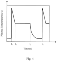
- FIGs. 4 and 5 illustrate time variations of gas temperature in the systems and methods of the present disclosure that occur due to pulsing of the microwave radiation.
- FIG. 4 illustrates a typical time variation of the plasma temperature within a reaction chamber when microwave radiation that is coupled into the reaction chamber is pulsed.
- time t 1 indicates the start of a first pulse period
- time t 4 indicates the end of a first pulse period and the beginning of a second pulse period.
- time t 1 to t 3 indicates a first duration of the pulse period where the microwave radiation is on
- time t 3 to t 4 indicates a second duration of the pulse period where the microwave radiation is off or at a lower power than during the duration when the microwave power is on.
- the duty cycle in this example is (t 3 -t 1 )/(t 4 -t 1 ) x 100, expressed as a percentage.
- a duty cycle of 30% indicates that the microwave radiation is on for 30% of each pulse period.
- the plasma temperature quickly rises due to the excitation of the high energy species in the plasma.
- the high energy species created at the start of the pulse are relatively short lived, and the plasma temperature decreases until a steady state is reached within the plasma.
- Time t 2 indicates the time where equilibrium is reached within the plasma in the reaction chamber.
- the energy in the plasma can be expressed as a plasma temperature (in units of eV), and describes the energy of the radical species in the plasma.
- the gas temperature in the reaction chamber or waveguide is also related to the energy of the plasma, since the energy from the plasma is transferred to the gas.
- Plasma efficiency is one property that affects the relationship between plasma energy and these temperatures, which is dominated by gas mixtures and types by innate gas plasma properties such as secondary electron emission coefficient, and pair production. Therefore, the average energy in the plasma between time t 1 and t 2 is higher than the average energy in the plasma at equilibrium (between times t 2 and t 3 ). As the total pulse period is shortened, there is a greater fraction of time where the high energy species exist within each pulse period.
- FIG. 5 shows an example graph of a pulse with a period that is shorter than the example pulse depicted in FIG. 4 .
- the pulsing may be, for example, greater than 500 Hz, such as greater than 100 kHz, and up to 1000 kHz. Since the total pulse period is shorter, but the duration of time within the pulse period where the high energy species exist is the same, the fraction of time where high energy species exist, (t 2 -t 1 )/(t 4 -t 1 ) is larger for the example shown in FIG. 5 than it is for the example shown in FIG. 4 .
- the higher energy level resulting from high frequency pulsing of the microwave radiation enables more efficient cracking of the process gas molecules, by utilizing increased thermal cracking in addition to kinetic mechanisms.
- the increased contribution of thermal cracking results in less power input required, consequently also enabling higher flow rates of the process gas to be used.
- the rise time and fall time of the pulse is from 5 nS to 1000 mS, or from 5 nS to 10 mS.
- the average energy in the plasma is controlled by changing the pulse period, by choosing a pulsing frequency to achieve a desired plasma energy. Additionally, in some embodiments, the average energy of the plasma is controlled by controlling the duty cycle. This can be understood by contemplating the situation where the time-averaged input power and the pulse period are both held constant and the duty cycle is varied. A shorter duty cycle will increase the magnitude of the power coupled into the chamber when the microwave radiation is on. That is because the time-averaged power is held constant and the duration that the power is on (i.e., the duty cycle) is shorter. In some embodiments, the higher power coupled into the reaction chamber during the first duration of the pulse period will increase the average temperature and average energy of the plasma.
- controlling the energy of the plasma can be used to select given reaction pathways for the creation of separated components from a process gas. Therefore, in some embodiments, the reaction pathways can be selected by controlling the duty cycle of the microwave radiation coupled into the reaction chamber. This is advantageous because a relatively low amount of power (i.e., time-averaged power) can be used to generate reaction products from reaction pathways that would be impossible to facilitate at the same power in a continuous wave.
- the reaction pathways can be selected by controlling time-averaged power input into the plasma. For example, if the duty cycle and pulse frequency are held constant, and the power input into the microwave generator is increased, then the energy of the plasma will increase. By way of another example, if the duty cycle and pulse frequency are held constant, and the power is more effectively coupled into the reaction chamber, then the energy of the plasma will increase.
- the reaction pathways can be selected by controlling a shape of the microwave radiation pulse.
- the microwave pulse is a rectangular wave, where the power is constant during the duration of the pulse period when the microwave is on. In some embodiments, the pulse power is not constant during the duration of the pulse period when the microwave power is on. In some embodiments, the microwave pulse is a triangular wave, or a trapezoidal wave. In some embodiments, the pulse quickly rises to a value E1 (e.g., at time t 1 in FIG. 5 ) and then increases over some period of time up to a value E2 (e.g., at time from t 1 to t 2 in FIG. 5 ).
- the pulse quickly rises to a value E1 (e.g., at time t 1 in FIG. 5 ) and then linearly increases over some period of time up to a value E2 (e.g., at time from t 1 to t 2 in FIG. 5 ).
- the pulse quickly rises to a value E1 (e.g., at time t 1 in FIG. 5 ), then increases over some period of time to a value E2 (e.g., at time from t 1 to t 2 in FIG. 5 ), and then quickly decreases to a low value E0 (e.g., from time t 2 to t 3 in FIG. 5 ) less than E1 and greater than the value of the energy when the microwave power is off.
- the plasma can be referred to as diffuse during the time period when the high energy species exist in higher fractions (i.e., at the beginning of the pulse, before the plasma reaches equilibrium).
- the microwave energy increases over the time period where the plasma is diffuse, which increases the time average fraction of high energy species in the plasma.
- tuning the pulse frequency, duty cycle, and pulse shape can enable the creation of a higher fraction of higher energy species within the plasma for a given time-averaged input power.
- the higher energy species can enable additional reaction pathways that would otherwise not be energetically favorable.
- methane (CH 4 ) as an example process gas, to be separated into hydrogen and nanoparticulate carbon.
- 4-6 eV is needed to dissociate methane (CH 4 ); however, the plasma energy typically settles at approximately 1.5 eV after an initial ignition energy spike.
- the average plasma energy i.e. time-averaged plasma energy
- pulsing parameters such as frequency and duty cycle can be controlled to provide an average plasma energy of 4-6 eV to select specific dissociation reactions of the methane.
- Another advantage of pulsing the microwave energy is that the energy is more distributed throughout the chamber in which microwave is being input.
- the plasma forms a dense layer of ionized species in the chamber towards the location of the microwave input, which absorbs the incoming microwave radiation and consequently prevents further microwave radiation from penetrating deeper into the chamber.
- the high frequency pulsing of the present disclosure maintains the plasma in a non-equilibrium state for a greater fraction of time and the dense layer of ionized species is present for a smaller fraction of time, which allows the microwave radiation to penetrate deeper into the chamber and the plasma to be generated in a larger volume within the chamber.
- the process gas including methane can be reacted into CH 3 radicals and free H atoms and into CH 2 plus H 2 .
- the process gas including methane can be reacted into CH 3 radicals and free H atoms, and into CH 2 plus H 2 , and into CH radicals plus H 2 .
- the process gas including methane can be reacted into CH 3 radicals and free H atoms, and into CH 2 plus H 2 , and into CH radicals plus H 2 , and into C plus H 2 .
- the average energy of the plasma over the entire duration of the pulse period may be from 0.9 eV to 20 eV, or from 0.9 to 10 eV, or from 1.5 eV to 20 eV, or from 1.5 eV to 10 eV, or greater than 0.9 eV, or greater than 1.5 eV.
- the specific values to which the plasma energy is tuned will depend on the type of process gas being utilized.
- the microwave radiation source is controlled by a microwave emitter circuit (e.g., 207 in FIG. 2 , and 307 in FIG. 3 ), that can control the microwave radiation emitted from the source to be either continuous wave or pulsed.
- the microwave emitter circuit produces microwave radiation through the use of a magnetron, e.g., at 915 MHz, 2.45 GHz, or 5.8 GHz.
- the microwave emitter circuit may pulse the magnetron at various frequencies and duty cycles.
- Each microwave emitter circuit is designed for a specific range of pulsing frequency, duty cycle, shape, and output power level, where the selection of specific values of these parameters is used to tune the chemical reaction pathways in the process gas.
- the microwave control circuit enables a pulse frequency from 500 Hz to 1000 kHz, or from 1 kHz to 1000 kHz, or from 10 kHz to 1000 kHz, or from 40 kHz to 80 kHz, or from 60 to 70 kHz, or greater than 10 kHz, or greater than 50 kHz, or greater than 100 kHz.
- the microwave source emits continuous wave or pulsed microwave radiation with a time-average power from 1 to 100 kW.
- the pulse period has a first duration where the microwave power is on, and a second duration where the microwave radiation is off or at a lower power than during the first duration. In some embodiments, the second duration is longer than the first duration.
- the optimal duty cycle for a given system depends on many factors including the microwave power, pulse frequency, and pulse shape.
- the duty cycle i.e., the fraction of the pulse period where the microwave radiation is on, expressed as a percentage
- the duty cycle is from 1% to 99%, or from 1% to 95%, or from 10% to 95%, or from 20% to 80%, or from 50% to 95%, or from 1% to 50%, or from 1% to 40%, or from 1% to 30%, or from 1% to 20%, or from 1% to 10%, or less than 99%, or less than 95%, or less than 80%, or less than 60%, or less than 50%, or less than 40%, or less than 30%, or less than 20%, or less than 10%.
- FIG. 6 illustrates controlling ion energy of the plasma through the addition of one or more precursor gases, where the precursor gases are inserted upstream from where the process gas is flowed into the waveguide chamber.
- Precursor gases improve cracking efficiency by adding species of various ionization potentials. That is, different gases have different ionization energies, which is the amount of energy required to remove an electron from an atom or molecule is.
- various gases have different pair production (how many electrons per ion can be produced) and secondary electron emission properties (emission of electrons when the charged particles strike a surface).
- the use of precursor gases is utilized to affect the energy of the plasma.
- a microwave gas processing system 600 includes a microwave radiation source 604, a waveguide 605, and a microwave emitter circuit 607 similar to previous embodiments.
- the diagram of FIG. 6 is a simplified drawing compared to the previous figures for clarity.
- a supply gas inlet 602 receives a precursor gas 620 which supplements the supply gas (not shown) to create the plasma in the waveguide.
- the precursor gas 620 may include one or more of hydrogen, argon, helium, or various noble gases.
- Process gas inlet 610 is configured to receive the process gas that is to be reacted, similar to previous embodiments.
- precursor gases that are not desired output products of the system e.g., argon precursor gas in processing of methane
- the precursor gases are removed from the separated components 630 and 632 that are output from outlet 603 in post-process steps.
- one or more of the separated components of the process gas are recycled back into the supply gas and/or process gas entering the waveguide 605.
- gas reactions in the waveguide 605 produce separated components 630 and 632.
- first separated component 630 may be CH 3 and second separated component 632 may be atomic hydrogen H + which recombines to form H 2 gas before being collected at the outlet 603.
- first separated component 630 may be CH 2 and second separated component 632 may be hydrogen gas H 2 .
- the separated component 632 is recycled back into waveguide 605 through conduit 640, back to supply gas inlet 602. The recycled separated component 632 thus is used as a precursor gas 620.
- separated component 632 can be 2-10 slm of H 2 that is recycled back into the waveguide 605, for a process in which a total of 150-200 slm of H 2 is produced. Other amounts or portions of separated component 632 may be recycled, as determined by factors such as the flow rate of the process gas, and/or the amount of energy desired to be added to the process to initiate the targeted chemical pathways.
- the supply gas contains one or more recycled separated components of the process gas.
- the supply gas can be hydrogen
- the process gas can be methane, which is reacted to form hydrogen and carbon, and at least a portion of the hydrogen that is produced from the methane can be recycled and used as the supply gas. Recycling the produced hydrogen beneficially improves the efficiency of the overall gas processing because the plasma formed from the hydrogen is highly efficient at cracking hydrocarbon bonds in the process gas molecules. Additionally, in some embodiments, the recycled H 2 is already at a high temperature, and thus less energy input is need to achieve a thermal cracking energy.
- the supply gas is H 2 provided by an external source, to which recycled H 2 is added. In such embodiments the generated plasma is a hydrogen plasma.
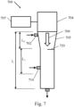
- FIG. 7 illustrates another technique for controlling the chemical pathways, through the use of filaments.
- the microwave processing system 700 includes a microwave radiation source 704, a waveguide 705, and a microwave emitter circuit 707 similar to previous embodiments.
- Microwave radiation 709 is supplied by the microwave radiation source 704, to propagate in a direction down the length L of the waveguide 705.
- supply gas inlet 702 is placed near the entrance of the portion L 0 , rather than at the entrance to the portion L 1 as was illustrated in previous embodiments.
- One or more metal filaments 720 is placed within waveguide 705 to assist in the ignition of the plasma and/or the excitation of higher energy species within the plasma.
- metal filament 720 is downstream of the first gas inlet 702, near the entrance to the portion L 1 that has a constant cross-sectional area.
- the filament 720 may be located at other locations within portion L 1 of the overall length L of the waveguide 705, where L 1 is the region in the waveguide where the plasma is formed as described in relation to previous embodiments.
- the filament 720 is located within portion L 1 and upstream of the process gas inlet 710, so that it will be located outside of the portion L 2 (shown in FIGs. 2 and 3 ) where reactions are taking place and which could coat the filament with reacted species.
- the presence of filament 720 can reduce the plasma ignition voltage by providing an ignition site, by focusing the electric field of microwave radiation 709.
- the filament 720 can become heated and emit electrons through thermionic emission, which further contributes to reducing the plasma ignition voltage.
- the filament 720 is illustrated as a single wire in this embodiment, filament 720 may take other configurations such as a coil or multiple filaments.
- the filament 720 is tungsten.
- the filament may be actively energized (powered) or may be passive.
- the filament 720 is an osmium filament (e.g., configured as a plate, or coil, or other shape) adjacent to a heater coil.
- the filament 720 is a ferrous material in the field of an inductive coil.
- the filament 720 is actively heated where the active components (e.g. heating source components) are located outside of the waveguide 705 and the filament material that is being heated is inside of the waveguide 705.
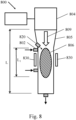
- FIG. 8 illustrates yet further techniques for controlling the plasma energy, through the use of an electron source.
- Microwave processing system 800 includes a supply gas inlet 802, a waveguide 805, and a microwave radiation source 804 that supplies microwave radiation 809 as in previous embodiments.
- Microwave processing system 800 also includes one or more electron sources 820 to assist in the ignition of the plasma and/or the excitation of higher energy species within the plasma.
- the electron source 820 is configured to inject electrons into the waveguide 805, thereby decreasing the amount of initial energy needed to ignite the plasma. The ignition level of the plasma can therefore be controlled by controlling the amount of electrons present.
- the electrons are injected into the portion L 1 of the overall length L of the waveguide 805, where L 1 is the region in the waveguide where the plasma is formed as described above.
- the electron source 820 is configured to supply electrons into the waveguide 805 downstream of the first gas inlet 802.
- the electron source 820 is a field emission source.
- the electron source 820 contains an osmium element adjacent to a heater coil.
- the electron source 820 contains a ferrous material in the field of an inductive coil.
- the electron source 820 contains a filament, as described above, and the generated electrons are injected into the portion L 1 using a high voltage electric field.
- the electron source 820 is alternatively a source of ions.
- An advantage of using a filament 720 and/or an electron source 820 within the waveguide is that they enable a plasma to form quickly enough to keep up with fast microwave pulsing frequencies (e.g., at frequencies greater than 500 Hz, or greater than 1 kHz), even with high gas flows (e.g., greater than 5 slm) and large gas volumes (e.g., up to 1000 L).
- fast microwave pulsing frequencies e.g., at frequencies greater than 500 Hz, or greater than 1 kHz
- high gas flows e.g., greater than 5 slm
- large gas volumes e.g., up to 1000 L.
- FIG. 8 also illustrates an embodiment of an electrode 830 in the present systems, as another technique for controlling chemical pathways.
- the electrode 830 may be used independently of, or in combination with, the precursor gases 620 of FIG. 6 , the filaments 720 of FIG. 7 or the electron source 820 of FIG. 8 .
- the system 800 contains one or more sets of electrodes 830 to add energy to the plasma.
- the electrodes are configured to generate an electric field within the portion L 1 of the overall length L of the waveguide 805, where L 1 is the region in the waveguide where the plasma is formed as described above.
- Electrode 830 is embodied in FIG.
- the electrodes can be energized to a particular voltage to accelerate the charged species within the plasma to a desired degree, thus controlling the plasma energy.
- the electrodes are particularly effective in combination with a pulsed microwave input. In conventional systems with electrodes and continuous microwave radiation, the plasma between electrodes will localize (e.g., near the electrodes) at equilibrium and screen the electric field from the electrodes, which limits the ability of the electrodes to add energy to the plasma. However, when the microwaves are pulsed, the plasma will exist in the non-equilibrium state for a larger fraction of time and will screen the electric field of the electrodes for a smaller fraction of time.
- the gas processing systems of the present disclosure will include magnets (not shown) to confine the plasma and reduce the ignition voltage.
- the magnets are permanent or are electromagnets.
- the magnets can be positioned so the plasma density distribution can be controlled.
- the magnets will increase the plasma density in the portion Li, which will improve the efficiency by which the process gas is separated by the plasma.
- the combination of pulsed microwave radiation, high gas flows e.g., greater than 5 slm
- large volumes of plasma e.g., up to 1000 L
- high pressures e.g., greater than 0.1 atm (10132.5 Pa) or greater than 0.9 atm (91192.5 Pa), or greater than 2 atm (202650 Pa)
- either filaments or electron sources to assist in plasma ignition at the start of each pulse, and/or electrodes to further add energy to the plasma can enable cost-effective high-productivity chemical gas processing systems, with low energy input requirements.
- the gas processing systems with the above features are configured in such a way that the plasma is generated and the process gas is separated into components within the waveguide itself, such as the examples depicted in FIGs. 2 , 3 , 6 , 7 and 8 .
- microwave radiation enters the system upstream of the reaction generating the separated components, and therefore the problem of the separated components building up on a microwave entry window of a reactor and absorbing the microwave radiation before it can generate the plasma is alleviated.
- the portion of the waveguide where the separated components are generated acts as a reaction chamber, and the supply gas flow and/or the process gas flow through the reaction chamber is parallel to the propagation direction of the microwave radiation.
- the microwave radiation enters the reaction chamber upstream of the portion of the reaction chamber where the separated components are generated.
- the separated components can adhere to the walls of the waveguide downstream of the reaction generating the separated components, despite the large volume of the reaction volume in the waveguide. Although this does not prevent the plasma from being generated, it still represents a loss of production and a source of contamination in the system. Therefore, in some embodiments, the gas flow of the supply gas and the process gas can be designed to generate a plasma near the areas of deposition to remove the separated products that are deposited on the waveguide walls (or, reaction chamber walls). In some embodiments, additional inlets of supply gas and/or process gas can be configured to direct the gases to the areas of deposition to remove the separated products that are deposited on the waveguide walls (or, reaction chamber walls).
- FIG. 9 is an example flow chart 900 representing methods for microwave processing of gas, using chemistry control in high efficiency gas reactions.
- microwave radiation is supplied through a waveguide having a length, where the microwave radiation propagates in a direction along the waveguide.
- the microwave radiation may be pulsed or continuous wave.
- the microwave radiation is supplied into the waveguide at a power less than 100 kV.
- a pressure within the waveguide is at least 0.1 atmosphere, such as from 0.9 atm to 10 atm.
- a supply gas is provided into the waveguide at a first location along the length of the waveguide, where a majority of the supply gas is flowing in the direction of the microwave radiation propagation.
- a plasma is generated in the supply gas in at least a portion of the length of the waveguide.
- a process gas is added into the waveguide at step 940, at a second location downstream from the first location. A majority of the process gas flows in the direction of the microwave propagation at a flow rate of greater than 5 slm.
- an average energy of the plasma is controlled to convert the process gas into separated components.
- the average energy may be, for example, 0.8 eV to 20 eV.
- the pulsing frequency is controlled, where the pulsing frequency is greater than 500 Hz.
- the pulsing frequency of the microwave radiation may be from 500 Hz to 1000 kHz.
- the duty cycle of the pulsed microwave radiation is controlled in addition to or instead of the pulsing frequency, where the duty cycle is less than 50%.
- the process gas is methane
- the separated components comprise hydrogen and a nanoparticulate carbon.
- the nanoparticulate carbon can include one or more forms of graphene, graphite, carbon nano-onions, fullerenes or nano-tubes.
- a precursor gas is added to the supply gas at the first location, the precursor gas comprising hydrogen or a noble gas.
- the separated components comprise H 2 , and at least a portion of the separated component H 2 is recycled back to the first location.
- the supply gas comprises H 2
- the plasma comprises a hydrogen plasma.
- the methods include providing a metal filament in the waveguide, the metal filament serving to reduce an ignition voltage for generating the plasma. In various embodiments, the methods include providing a pair of electrodes coupled to the waveguide, wherein the electrodes are configured to add energy to the generated plasma.
Landscapes
- Chemical & Material Sciences (AREA)
- Physics & Mathematics (AREA)
- Engineering & Computer Science (AREA)
- Plasma & Fusion (AREA)
- Analytical Chemistry (AREA)
- Chemical Kinetics & Catalysis (AREA)
- Electromagnetism (AREA)
- Toxicology (AREA)
- Health & Medical Sciences (AREA)
- General Health & Medical Sciences (AREA)
- Organic Chemistry (AREA)
- Spectroscopy & Molecular Physics (AREA)
- Oil, Petroleum & Natural Gas (AREA)
- General Chemical & Material Sciences (AREA)
- Plasma Technology (AREA)
- Physical Or Chemical Processes And Apparatus (AREA)
- Drying Of Semiconductors (AREA)
- Hydrogen, Water And Hydrids (AREA)
- Carbon And Carbon Compounds (AREA)
- Control And Other Processes For Unpacking Of Materials (AREA)
Description
- This application claims priority to
U.S. Non-Provisional Patent Application No, 15/351,858, filed on November 15, 2016 - Microwave plasmas are used in the industrial chemical processing of gases. This is typically accomplished by flowing the gases to be reacted through an elongated vessel while microwave radiation is coupled into the vessel to generate a plasma. The plasma cracks the gas molecules into component species. Microwave chemical processing systems are effective because microwave plasmas operate at relatively high power coupling efficiencies at low ion energies, and are capable of supporting various gas reactions, such as the conversion of methane into hydrogen and carbon particulates, the conversion of carbon dioxide into oxygen and carbon, and coating particulates and other seed materials with other layers for functionalization and complex layered materials and aggregates processing.
- Typical systems for chemical gas processing include a quartz reaction chamber through which process gases flow, and a microwave magnetron source coupled to the reaction chamber through a waveguide. The input microwave radiation can be continuous wave or pulsed. Systems are designed to control the effective coupling of the microwave radiation into the reaction chamber, and the gas flow within the reaction chamber to improve the energy absorption by the flowing gas. Often the systems include a wedge located where the microwave waveguide intersects the quartz reaction chamber, to concentrate the electric field within a small area, and the waveguide conductive walls are not exposed to the gases to be processed.
- One example of chemical processing is the microwave processing of methane to produce hydrogen. Methane can be cracked by a plasma into CHX radicals and H-atoms. When such systems are operated in continuous mode, the H-atom density is mainly controlled by the gas temperature, which is directly related to the microwave power density, and in some cases by diffusion processes. The CHX radical density, likewise, is controlled by the gas temperature and H-atom concentrations. Alternatively, when such systems are operated in pulsed mode, H-atom and CHX radical production is controlled by in-pulse power density and its associated higher plasma kinetic energy, which controls gas temperature and thermal dissociation. Typically, during the time the plasma is off the H-atoms recombine and are consumed. Short duty cycles are used to increase the in-pulse power for a constant time-averaged power, and short off-plasma times are used to limit H-atom recombination. Therefore, pulsed systems crack the methane into hydrogen and other hydrocarbon radicals more efficiently (i.e., using less time-averaged input power) than continuous wave systems.
US 2008/0029030 discloses a tubular casing into which a gas and a microwave are introduced for stably generating a plasma at atmospheric pressure.
US 2014/159572 discloses a method for processing a gas and a device for performing the method.US 2007/266825 discloses high volume production of nanostructured materials. - The present invention is defined in and by the appended claims.
-
- FIG. lis a vertical cross-section of a conventional microwave chemical processing system.
-
FIG. 2 is a vertical cross-section of a microwave gas processing system in accordance with some embodiments of the present disclosure. -
FIG. 3 is a vertical cross-section of a microwave gas processing system in accordance with further embodiments of the present disclosure. -
FIG. 4 is a graph of time variation of plasma temperature within a reaction chamber in accordance with embodiments of the present disclosure. -
FIG. 5 is a graph of time variation of plasma temperature within a reaction chamber, where the pulsing period is shorter than that ofFIG. 4 . -
FIG. 6 is a vertical cross-section of a microwave gas processing system with precursor gas input, in accordance with embodiments of the present disclosure. -
FIG. 7 is a vertical cross-section of a microwave gas processing system having a filament, in accordance with embodiments of the present disclosure. -
FIG. 8 is a vertical cross-section of a microwave gas processing system in which an electron source and an electrode are depicted, in accordance with embodiments of the present disclosure. -
FIG. 9 is an example flow chart of methods for microwave processing of a gas in accordance with embodiments of the present disclosure. - Reference now will be made to embodiments of the disclosed invention, one or more examples of which are illustrated in the accompanying drawings. Each example is provided by way of explanation of the present technology, not as a limitation of the present technology. In fact, it will be apparent to those skilled in the art that modifications and variations can be made in the present technology without departing from the scope thereof. For instance, features illustrated or described as part of one embodiment may be used with another embodiment to yield a still further embodiment. Thus, it is intended that the present subject matter covers all such modifications and variations within the scope of the appended claims and their equivalents.
- The present disclosure relates to microwave plasma chemical processing of hydrocarbon gases. More specifically, the present disclosure relates to microwave plasma chemical processing of hydrocarbon gases using various techniques including pulsing of the microwave radiation to control the energy of the plasma. The ability to control the energy of the plasma enables the selection of one or more reaction pathways in conversion of the hydrocarbon gases into specific separated components. Pulsed microwave radiation can be used to control the energy of the plasma because the short-lived high-energy species that are created when a plasma ignites can be re-generated at the start of each new pulse. The plasma energy is controlled to have a lower average ion energy than conventional techniques, but at a high enough level to enable the targeted chemical reactions to occur at high gas flows and high pressures.
- Microwave plasma chemical processing systems using pulsed microwave radiation have been developed that control the energy of the plasma and have very high cracking efficiency, in excess of 90%. These conventional systems, however, use low flow rates, below 1 standard liter per minute (slm), and small gas volumes within the plasma, with a consequence that the production rate is low and the production cost is high. These conventional systems cannot increase the gas flow rate and the gas volume within the plasma while using high frequency microwave pulsing (e.g., above roughly 100 Hz) because the plasma cannot ignite fast enough to keep up with the pulses when a large volume and high flow of gas is used.
- In the present disclosure, a microwave plasma can be generated in a supply and/or process gas, and the energy in the plasma is sufficient to form separated components from process gas molecules. In some embodiments, a source of microwave radiation is coupled to a reaction chamber, the plasma is generated along a first portion of the length of the reaction chamber, and the process gas is separated into components along a second portion of the length of the reaction chamber. In some embodiments, the microwave radiation is coupled directly into the plasma and not through a dielectric wall as in conventional methods.
-
FIG. 1 illustrates a conventional microwave chemical processing system. As shown inFIG. 1 , a microwavechemical processing system 100 generally includes areaction chamber 101, one ormore gas inlets 102 configured to receive process gas flowing into the reaction chamber, one ormore outlets 103 configured to collect separated products out of thereaction chamber 101, and a source ofmicrowave radiation 104 that is coupled to the reaction chamber through awaveguide 105, among other elements not shown for simplicity. Themicrowave radiation 109 creates amicrowave plasma 106 in thereaction chamber 101, and provides energy for reactions to occur. Amicrowave emitter circuit 107 can control themicrowave radiation 109 emitted from themicrowave radiation source 104 to be either continuous wave or pulsed. Given the right conditions, the energy in the plasma will be sufficient to form separated components from the process gas molecules. -
FIGs. 2 and3 show embodiments of microwave gas processing systems of the present disclosure, in which a waveguide coupled to a microwave source serves as the reaction chamber. The direction of propagation of the microwave radiation is parallel to the majority of the flow of the supply gas and/or the process gas, and the microwave radiation enters the waveguide upstream of the portion of the waveguide where the separated components are generated. - As shown in
FIG. 2 , a microwavechemical processing system 200, in accordance with some embodiments, generally includes awaveguide 205, one ormore gas inlets 202 configured to receive supply gas and/orprocess gas 208a flowing into thewaveguide 205, and amicrowave radiation source 204 that is coupled to thewaveguide 205, among other elements not shown for simplicity. - In some embodiments,
microwave circuit 207 controls a pulsing frequency at whichmicrowave radiation 209 frommicrowave radiation source 204 is pulsed. - The
waveguide 205 has a length L. In a portion Lo prior to where the plasma is generated, the cross-sectional area of thewaveguide 205 decreases along the path of the microwave propagation. This decrease in area serves to concentrate the electric field, thus increasing the microwave energy density while still providing a significant amount of area in which plasma can be formed compared to conventional systems. For example, the decreased cross-sectional area of portion L0, where thegas inlet 202 is located, may have a rectangular cross-section of dimensions 0.75 inches (1.9 cm) by 3.4 inches (8.6cm) when using a microwave radiation frequency of 2.45 GHz. This cross-sectional area is much greater than conventional systems where the plasma generation area is generally less than one square inch (6.5 cm2). The dimensions of thewaveguide 205 are set according to the microwave frequency, in order to properly function as a waveguide. - In conventional gas processing systems, the limited region in which plasma can form, such as less than one square inch (6.5 cm2) as described above, constrains the volume in which gas reactions can occur. Also, in conventional systems the microwave radiation enters the reaction chamber through a window (typically quartz). In these systems, dielectric materials (e.g., particulate carbon) are coated on the window during processing leading to less and less power delivery over time. This can be highly problematic if these separated components absorb microwave radiation because they can prevent the microwave radiation from coupling into the reaction chamber to generate the plasma. Consequently, a rapid build-up of by-products, such as carbon particles that are produced from the gas reactions, occurs and limits the run-time of the processing equipment. In the present embodiments, the
system 200 and other embodiments described below are designed without the use of a window; that is, using a parallel propagation / gas flow system where the radiation enters upstream from the reaction. As a result, more energy and power can be coupled into the plasma from the microwave radiation source. The greater volume within thewaveguide 205, compared to limited reaction chamber volumes in conventional systems, greatly reduces the issue of particle build-up causing limited run-times, thus improving production efficiency of the microwave processing system. - The
microwave radiation 209 inFIG. 2 creates amicrowave plasma 206 in the supply gas and/or process gas within a first portion L1 of the length of thewaveguide 205. In some embodiments, a supply gas that is different from the process gas is used to generate themicrowave plasma 206. The supply gas may be, for example, hydrogen, helium, a noble gas such as argon, or mixtures of more than one type of gas. In other embodiments, the supply gas is the same as the process gas, where the process gas is the gas from which separated components are being created. In some embodiments, L1 extends from a position along the waveguide downstream from the position where the supply and/orprocess gas 208a enters thewaveguide 205, to the end of thewaveguide 205 or to a position between the entrance of the supply and/or process gas and the end of thewaveguide 205. In some embodiments, Li extends from where the supply and/orprocess gas 208a enters thewaveguide 205, to the end of thewaveguide 205 or to a position between the entrance of the supply and/or process gas and the end of thewaveguide 205. The generatedplasma 206 provides energy for reactions to occur inprocess gas 208b within asecond portion 201 of thewaveguide 205, thesecond portion 201 having a length L2. In some embodiments, L2 extends from where theprocess gas 208a enters thewaveguide 205, to the end of thewaveguide 205 or to a position between the entrance of the process gas and the end of thewaveguide 205. Given the right conditions, the energy in theplasma 206 will be sufficient to form separated components from the process gas molecules. One ormore outlets 203 are configured to collect the separated products out of thewaveguide 205 downstream of theportion 201 of the waveguide where reactions occur in theprocess gas 208b. In the example shown inFIG. 2 , the propagation direction of themicrowave radiation 209 is parallel with the majority of the supply and/orprocess gas flow 208b, and themicrowave radiation 209 enters thewaveguide 205 upstream of theportion 201 of the waveguide where the separated components are generated. - In some embodiments, a plasma backstop (not shown) is included in the system to prevent the plasma from propagating to the
microwave radiation source 204 or the gas inlet(s) 202. In some embodiments, the plasma backstop is a ceramic or metallic filter with holes to allow the microwave radiation to pass through the plasma backstop, but preventing the majority of the plasma species from passing through. In some embodiments, the majority of the plasma species will be unable to pass the plasma backstop because the holes will have a high aspect ratio, and the plasma species will recombine when they hit the sidewalls of the holes. In some embodiments, the plasma backstop is located between portion Lo and Li, or in portion Lo upstream of portion Li and downstream of the gas inlet(s) 202 (in an embodiment wheregas inlet 202 is within portion Lo) and themicrowave radiation source 204. -
FIG. 3 shows another embodiment of a microwavechemical processing system 300 in which a supply gas and a process gas are injected at different locations. The microwavechemical processing system 300, in accordance with some embodiments, generally includes awaveguide 305, one or moresupply gas inlets 302 configured to receivesupply gas 308a flowing into thewaveguide 305, one or moreprocess gas inlets 310 configured to receiveprocess gas 311a, and a source ofmicrowave radiation 304 that is coupled to thewaveguide 305, among other elements not shown for simplicity. The location ofprocess gas inlet 310 is downstream of the location ofsupply gas inlet 302, where downstream is defined in a direction of the microwave propagation. - In some embodiments,
microwave circuit 307 controls a pulsing frequency at whichmicrowave radiation 309 frommicrowave radiation source 304 is pulsed. - The
waveguide 305 has a length L. The length Lo of the waveguide wheremicrowave radiation 309 enters has a decreasing cross-sectional area along the direction of the microwave propagation, as described above in relation toFIG. 2 . Themicrowave radiation 309 creates amicrowave plasma 306 in thesupply gas 308b within a first portion Li of the length L of thewaveguide 305. In some embodiments, Li extends from a position along thewaveguide 305 downstream from the position where thesupply gas 308a enters thewaveguide 305, to the end of thewaveguide 305 or to a position between the entrance of the supply gas and the end of thewaveguide 305. In some embodiments, Li extends from where thesupply gas 308a enters thewaveguide 305, to the end of thewaveguide 305 or to a position between the entrance of the supply gas and the end of thewaveguide 305. One or more additionalprocess gas inlets 310 are configured to receive process gas flowing into the waveguide at a second set oflocations downstream of the supply gas inlet(s) 302. The generatedplasma 306 provides energy for reactions to occur within asecond portion 301 of thewaveguide 305, thesecond portion 301 having a length L2. In some embodiments, L2 extends from where theprocess gas 311a enters thewaveguide 305, to the end of thewaveguide 305 or to a position between the entrance of the process gas and the end of thewaveguide 305. Given the right conditions, the energy in the plasma will be sufficient to form separated components from the process gas molecules. One ormore outlets 303 are configured to collect the separated products out of thewaveguide 305 downstream of theportion 301 where reactions occur. In theexample system 300 shown inFIG. 3 , the propagation direction of themicrowave radiation 309 is parallel with the majority of thesupply gas flow 308b and theprocess gas flow 311b, and themicrowave radiation 309 enters thewaveguide 305 upstream of theportion 301 of the waveguide where the separated components are generated. - As described above, the waveguide (e.g., 205 in
FIG. 2 , and 305 inFIG. 3 ) has a total length L, a portion of the total length L1 along which the plasma is generated, and a portion of the total length L2 along which the process gas is converted into the separated components. In some embodiments, the total length L of the waveguide is from 1 cm to 1000 cm. In some embodiments, length L0 of the waveguide is from 1 cm to 100 cm. In some embodiments, length L1 of the waveguide is from 1 cm to 100 cm. In some embodiments, length L2 of the waveguide is from 1 cm to 1000 cm. In some embodiments, the total length L of the waveguide is from 30 cm to 60 cm. In some embodiments, length L0 of the waveguide is from 10 cm to 40 cm. In some embodiments, length L1 of the waveguide is from 10 cm to 30 cm. In some embodiments, length L2 of the waveguide is from 5 cm to 20 cm. In some embodiments, length L1 is more than 10%, or more than 20%, or more than 30% or more than 40% or more than 50%, or more than 60%, or more than 70%, or more than 80%, or from 10% to 90%, or from 20% to 80%, or from 30% to 70% of the length of the waveguide, L. In some embodiments, length L2 is more than 5%, or more than 10%, or more than 15% or more than 20%, or more than 25% or more than 30%, or more than 35%, or more than 40%, or more than 45%, or more than 50%, or more than 55%, or more than 60%, or from 1% to 90%, or from 1% to 70%, or from 1% to 50%, or from 10% to 50%, or from 10% to 40%, or from 20% to 40% of the length of the waveguide, L. - In some embodiments, the waveguide (e.g., 205 in
FIG 2 , and 305 inFIG. 3 ) is configured to maintain a pressure from 0.1 atm to 10 atm (10132.5 Pa to 1013250 Pa), or from 0.5 atm to 10 atm (50662.5 Pa to 1013250 Pa), or from 0.9 atm to 10 atm (91192.5 Pa to 1013250 Pa), or greater than 0.1 atm (10132.5 Pa), or greater than 0.5 atm (50662.5 Pa), or greater than 0.9 atm (91192.5 Pa). In many conventional systems, the microwave chemical processing is operated at vacuum. However, in the present embodiments with the plasma being generated within the waveguide, operating in a positive pressure environment assists in preventing the generated plasma from feeding back into themicrowave emitter source - The waveguide (e.g., 205 in
FIG. 2 , and 305 inFIG. 3 ) may have a rectangular cross-section within length L1 of dimensions 0.75 inches(1.9 cm) by 3.4 inches (8.6 cm), to correspond to a microwave radiation frequency of 2.45 GHz. Other dimensions are possible for other microwave frequencies, and dependent upon waveguide mode this can be from 3-6 inches (7.62 - 15.2 cm). The waveguide may be made of any innately conductive material or a material with a sufficient conductive coated layer to propagate greater than 90% of incoming power. Some examples of waveguide materials are stainless steel, stainless steel coated with a conductive layer (e.g., Al, Ni, Au, or aNi/Au alloy), stainless steel with an aluminum liner, or a ceramic materials coated with a conductive layer. Notably, the waveguide serves as the chamber in which the plasma is generated and the process gas reactions to occur, rather than having a separate waveguide and quartz reaction chamber as in conventional systems. Having the waveguide serve as the reactor chamber provides a much larger volume in which gas reactions can occur (e.g., up to 1000 L). This enables high flow rates of process gas to be processed, without being limited by a build-up of carbon particulate as occurs in conventional systems. For example, process gas flow rates through the inlet (e.g., 202 inFIG. 2 , and 310 inFIG. 3 ) into the waveguide (e.g., 205 inFIG. 2 , and 305 inFIG. 3 ) may be from 5 slm to 1000 slm, or greater than 5 slm. Supply gas flow rates through the inlet (e.g., 202 inFIG. 2 , and 302 inFIG. 3 ) into the waveguide (e.g., 205 inFIG. 2 , and 305 inFIG. 3 ) may be, for example, from 1 slm to 1000 slm, or from 2 slm to 1000 slm, or from 5 slm to 1000 slm, or greater than 1 slm, or greater than 2 slm, or greater than 5 slm. Dependent upon the gas plasma properties that result in sufficient plasma density (e.g., secondary electron emission coefficient) the flows can be from 1 slm to 1000 slm and with pressures up to 14 atm. - In some embodiments, the process gas is a hydrocarbon, such as C2H2, C2H4, C2H6. In some embodiments, the process gas is methane, and the separated components are hydrogen and nanoparticluate carbon. In some embodiments, the process gas is carbon dioxide with water, and the separated components are oxygen, carbon and water. In some embodiments, the process gas is H2S and the separated components are hydrogen gas and sulfur. In some embodiments, the process gas does not contain carbon dioxide. In some embodiments, the process gas is a complex gas-based material, for example SiH4, trimethylaluminum (TMA), trimethylgallium (TMG), glycidyl methacrylate (GMA), SF6, and other materials used in the semiconductor industry for the deposition and etching of metals and dielectrics.
- In some embodiments, one of the separated components is nanoparticulate carbon such as, but not limited to, carbon black, carbon nano-onions (CNOs), necked CNOs, carbon nanospheres, graphite, pyrolytic graphite, graphene, graphene nanoparticles, graphene platelets, fullerenes, hybrid fullerenes, single-walled nanotubes and multi-walled nanotubes. One or more of these nanoparticulate carbons may be produced during a particular process run.
- Different process gases require different amounts of energy to react into different separated components. In the present disclosure, the available reaction pathways can be selected by changing the average energy of the plasma. In some embodiments, the microwave radiation coupled to the plasma is pulsed, and the average energy of the plasma, and therefore the reaction pathways, are selected by controlling the microwave radiation pulse duration and frequency, duty cycle, shape, and time-averaged output power level.
FIGs. 4 and5 illustrate time variations of gas temperature in the systems and methods of the present disclosure that occur due to pulsing of the microwave radiation. -
FIG. 4 illustrates a typical time variation of the plasma temperature within a reaction chamber when microwave radiation that is coupled into the reaction chamber is pulsed. InFIG. 4 , time t1 indicates the start of a first pulse period, and time t4 indicates the end of a first pulse period and the beginning of a second pulse period. Within the first pulse period, time t1 to t3 indicates a first duration of the pulse period where the microwave radiation is on, and time t3 to t4 indicates a second duration of the pulse period where the microwave radiation is off or at a lower power than during the duration when the microwave power is on. The duty cycle in this example is (t3-t1)/(t4-t1) x 100, expressed as a percentage. For example, a duty cycle of 30% indicates that the microwave radiation is on for 30% of each pulse period. Upon the initiation of the first pulse, the plasma temperature quickly rises due to the excitation of the high energy species in the plasma. However, the high energy species created at the start of the pulse are relatively short lived, and the plasma temperature decreases until a steady state is reached within the plasma. Time t2 indicates the time where equilibrium is reached within the plasma in the reaction chamber. - The energy in the plasma can be expressed as a plasma temperature (in units of eV), and describes the energy of the radical species in the plasma. The gas temperature in the reaction chamber or waveguide is also related to the energy of the plasma, since the energy from the plasma is transferred to the gas. Plasma efficiency is one property that affects the relationship between plasma energy and these temperatures, which is dominated by gas mixtures and types by innate gas plasma properties such as secondary electron emission coefficient, and pair production. Therefore, the average energy in the plasma between time t1 and t2 is higher than the average energy in the plasma at equilibrium (between times t2 and t3). As the total pulse period is shortened, there is a greater fraction of time where the high energy species exist within each pulse period.
- In accordance with the present embodiments,
FIG. 5 shows an example graph of a pulse with a period that is shorter than the example pulse depicted inFIG. 4 . The pulsing may be, for example, greater than 500 Hz, such as greater than 100 kHz, and up to 1000 kHz. Since the total pulse period is shorter, but the duration of time within the pulse period where the high energy species exist is the same, the fraction of time where high energy species exist, (t2-t1)/(t4-t1) is larger for the example shown inFIG. 5 than it is for the example shown inFIG. 4 . The higher energy level resulting from high frequency pulsing of the microwave radiation enables more efficient cracking of the process gas molecules, by utilizing increased thermal cracking in addition to kinetic mechanisms. The increased contribution of thermal cracking results in less power input required, consequently also enabling higher flow rates of the process gas to be used. In some embodiments, the rise time and fall time of the pulse is from 5 nS to 1000 mS, or from 5 nS to 10 mS. - In some embodiments, the average energy in the plasma is controlled by changing the pulse period, by choosing a pulsing frequency to achieve a desired plasma energy. Additionally, in some embodiments, the average energy of the plasma is controlled by controlling the duty cycle. This can be understood by contemplating the situation where the time-averaged input power and the pulse period are both held constant and the duty cycle is varied. A shorter duty cycle will increase the magnitude of the power coupled into the chamber when the microwave radiation is on. That is because the time-averaged power is held constant and the duration that the power is on (i.e., the duty cycle) is shorter. In some embodiments, the higher power coupled into the reaction chamber during the first duration of the pulse period will increase the average temperature and average energy of the plasma. As previously described, controlling the energy of the plasma can be used to select given reaction pathways for the creation of separated components from a process gas. Therefore, in some embodiments, the reaction pathways can be selected by controlling the duty cycle of the microwave radiation coupled into the reaction chamber. This is advantageous because a relatively low amount of power (i.e., time-averaged power) can be used to generate reaction products from reaction pathways that would be impossible to facilitate at the same power in a continuous wave.
- In some embodiments, the reaction pathways can be selected by controlling time-averaged power input into the plasma. For example, if the duty cycle and pulse frequency are held constant, and the power input into the microwave generator is increased, then the energy of the plasma will increase. By way of another example, if the duty cycle and pulse frequency are held constant, and the power is more effectively coupled into the reaction chamber, then the energy of the plasma will increase.
- In some embodiments, the reaction pathways can be selected by controlling a shape of the microwave radiation pulse. In some embodiments, the microwave pulse is a rectangular wave, where the power is constant during the duration of the pulse period when the microwave is on. In some embodiments, the pulse power is not constant during the duration of the pulse period when the microwave power is on. In some embodiments, the microwave pulse is a triangular wave, or a trapezoidal wave. In some embodiments, the pulse quickly rises to a value E1 (e.g., at time t1 in
FIG. 5 ) and then increases over some period of time up to a value E2 (e.g., at time from t1 to t2 inFIG. 5 ). In some embodiments, the pulse quickly rises to a value E1 (e.g., at time t1 inFIG. 5 ) and then linearly increases over some period of time up to a value E2 (e.g., at time from t1 to t2 inFIG. 5 ). In some embodiments, the pulse quickly rises to a value E1 (e.g., at time t1 inFIG. 5 ), then increases over some period of time to a value E2 (e.g., at time from t1 to t2 inFIG. 5 ), and then quickly decreases to a low value E0 (e.g., from time t2 to t3 inFIG. 5 ) less than E1 and greater than the value of the energy when the microwave power is off. The plasma can be referred to as diffuse during the time period when the high energy species exist in higher fractions (i.e., at the beginning of the pulse, before the plasma reaches equilibrium). In some embodiments, the microwave energy increases over the time period where the plasma is diffuse, which increases the time average fraction of high energy species in the plasma. - As described above, tuning the pulse frequency, duty cycle, and pulse shape can enable the creation of a higher fraction of higher energy species within the plasma for a given time-averaged input power. The higher energy species can enable additional reaction pathways that would otherwise not be energetically favorable.
- The techniques above can be further understood by using methane (CH4) as an example process gas, to be separated into hydrogen and nanoparticulate carbon. Typically, 4-6 eV is needed to dissociate methane (CH4); however, the plasma energy typically settles at approximately 1.5 eV after an initial ignition energy spike. By pulsing the microwave, the average plasma energy (i.e. time-averaged plasma energy) is maintained at the higher levels, where the frequency and duration of the pulsing controls the average plasma energy. Specifically, pulsing parameters such as frequency and duty cycle can be controlled to provide an average plasma energy of 4-6 eV to select specific dissociation reactions of the methane. Another advantage of pulsing the microwave energy is that the energy is more distributed throughout the chamber in which microwave is being input. In conventional systems, at equilibrium the plasma forms a dense layer of ionized species in the chamber towards the location of the microwave input, which absorbs the incoming microwave radiation and consequently prevents further microwave radiation from penetrating deeper into the chamber. The high frequency pulsing of the present disclosure maintains the plasma in a non-equilibrium state for a greater fraction of time and the dense layer of ionized species is present for a smaller fraction of time, which allows the microwave radiation to penetrate deeper into the chamber and the plasma to be generated in a larger volume within the chamber.
- Continuing with methane as an example, at the lowest energy applied to the process gas, only one hydrogen atom would be removed, producing CH3 radicals and free H atoms. When more energy is applied, the process gas including methane can be reacted into CH3 radicals and free H atoms and into CH2 plus H2. At even higher energies, the process gas including methane can be reacted into CH3 radicals and free H atoms, and into CH2 plus H2, and into CH radicals plus H2. At even higher energies, the process gas including methane can be reacted into CH3 radicals and free H atoms, and into CH2 plus H2, and into CH radicals plus H2, and into C plus H2. By controlling the amount of energy added to the plasma, different reaction pathways can be selected, and different products can be collected.
- More generally, in various embodiments of the present disclosure the average energy of the plasma over the entire duration of the pulse period may be from 0.9 eV to 20 eV, or from 0.9 to 10 eV, or from 1.5 eV to 20 eV, or from 1.5 eV to 10 eV, or greater than 0.9 eV, or greater than 1.5 eV. The specific values to which the plasma energy is tuned will depend on the type of process gas being utilized.
- In the microwave processing systems described above, the microwave radiation source is controlled by a microwave emitter circuit (e.g., 207 in
FIG. 2 , and 307 inFIG. 3 ), that can control the microwave radiation emitted from the source to be either continuous wave or pulsed. In some embodiments, the microwave emitter circuit produces microwave radiation through the use of a magnetron, e.g., at 915 MHz, 2.45 GHz, or 5.8 GHz. To control the output power of the microwave radiation, the microwave emitter circuit may pulse the magnetron at various frequencies and duty cycles. Each microwave emitter circuit is designed for a specific range of pulsing frequency, duty cycle, shape, and output power level, where the selection of specific values of these parameters is used to tune the chemical reaction pathways in the process gas. - In some embodiments, the microwave control circuit enables a pulse frequency from 500 Hz to 1000 kHz, or from 1 kHz to 1000 kHz, or from 10 kHz to 1000 kHz, or from 40 kHz to 80 kHz, or from 60 to 70 kHz, or greater than 10 kHz, or greater than 50 kHz, or greater than 100 kHz. In some embodiments, the microwave source emits continuous wave or pulsed microwave radiation with a time-average power from 1 to 100 kW. The pulse period has a first duration where the microwave power is on, and a second duration where the microwave radiation is off or at a lower power than during the first duration. In some embodiments, the second duration is longer than the first duration. The optimal duty cycle for a given system depends on many factors including the microwave power, pulse frequency, and pulse shape. In some embodiments, the duty cycle (i.e., the fraction of the pulse period where the microwave radiation is on, expressed as a percentage) is from 1% to 99%, or from 1% to 95%, or from 10% to 95%, or from 20% to 80%, or from 50% to 95%, or from 1% to 50%, or from 1% to 40%, or from 1% to 30%, or from 1% to 20%, or from 1% to 10%, or less than 99%, or less than 95%, or less than 80%, or less than 60%, or less than 50%, or less than 40%, or less than 30%, or less than 20%, or less than 10%.
- In addition to tuning various parameters of the microwave radiation pulsing to control which chemical reaction pathways occur in the process gas, other techniques shall now be discussed that can also affect the plasma energy and therefore tune the chemical reactions.
-
FIG. 6 illustrates controlling ion energy of the plasma through the addition of one or more precursor gases, where the precursor gases are inserted upstream from where the process gas is flowed into the waveguide chamber. Precursor gases improve cracking efficiency by adding species of various ionization potentials. That is, different gases have different ionization energies, which is the amount of energy required to remove an electron from an atom or molecule is. In addition, various gases have different pair production (how many electrons per ion can be produced) and secondary electron emission properties (emission of electrons when the charged particles strike a surface). Thus, in the present disclosure the use of precursor gases is utilized to affect the energy of the plasma. - In
FIG. 6 , a microwavegas processing system 600 includes amicrowave radiation source 604, awaveguide 605, and amicrowave emitter circuit 607 similar to previous embodiments. The diagram ofFIG. 6 is a simplified drawing compared to the previous figures for clarity. Asupply gas inlet 602 receives aprecursor gas 620 which supplements the supply gas (not shown) to create the plasma in the waveguide. In various embodiments, theprecursor gas 620 may include one or more of hydrogen, argon, helium, or various noble gases.Process gas inlet 610 is configured to receive the process gas that is to be reacted, similar to previous embodiments. For precursor gases that are not desired output products of the system (e.g., argon precursor gas in processing of methane), the precursor gases are removed from the separatedcomponents outlet 603 in post-process steps. - In some embodiments, one or more of the separated components of the process gas are recycled back into the supply gas and/or process gas entering the
waveguide 605. As shown inFIG. 6 , gas reactions in thewaveguide 605 produce separatedcomponents separated component 630 may be CH3 and secondseparated component 632 may be atomic hydrogen H+ which recombines to form H2 gas before being collected at theoutlet 603. Alternatively, firstseparated component 630 may be CH2 and secondseparated component 632 may be hydrogen gas H2. The separatedcomponent 632 is recycled back intowaveguide 605 throughconduit 640, back to supplygas inlet 602. The recycledseparated component 632 thus is used as aprecursor gas 620. Although it is counterintuitive to return the produced separated components back into the reaction system, recycling of the components adds energy to the plasma, and in some embodiments can also contribute to thermal cracking of the process gas since the recycled components have already been heated during the gas processing. In some embodiments, for example, separatedcomponent 632 can be 2-10 slm of H2 that is recycled back into thewaveguide 605, for a process in which a total of 150-200 slm of H2 is produced. Other amounts or portions of separatedcomponent 632 may be recycled, as determined by factors such as the flow rate of the process gas, and/or the amount of energy desired to be added to the process to initiate the targeted chemical pathways. - In some embodiments, some or all of the supply gas contains one or more recycled separated components of the process gas. For example, the supply gas can be hydrogen, and the process gas can be methane, which is reacted to form hydrogen and carbon, and at least a portion of the hydrogen that is produced from the methane can be recycled and used as the supply gas. Recycling the produced hydrogen beneficially improves the efficiency of the overall gas processing because the plasma formed from the hydrogen is highly efficient at cracking hydrocarbon bonds in the process gas molecules. Additionally, in some embodiments, the recycled H2 is already at a high temperature, and thus less energy input is need to achieve a thermal cracking energy. In some embodiments the supply gas is H2 provided by an external source, to which recycled H2 is added. In such embodiments the generated plasma is a hydrogen plasma.
-
FIG. 7 illustrates another technique for controlling the chemical pathways, through the use of filaments. In the embodiment ofFIG. 7 , themicrowave processing system 700 includes amicrowave radiation source 704, awaveguide 705, and amicrowave emitter circuit 707 similar to previous embodiments.Microwave radiation 709 is supplied by themicrowave radiation source 704, to propagate in a direction down the length L of thewaveguide 705. In this embodiment,supply gas inlet 702 is placed near the entrance of the portion L0, rather than at the entrance to the portion L1 as was illustrated in previous embodiments. One ormore metal filaments 720 is placed withinwaveguide 705 to assist in the ignition of the plasma and/or the excitation of higher energy species within the plasma. In this embodiment,metal filament 720 is downstream of thefirst gas inlet 702, near the entrance to the portion L1 that has a constant cross-sectional area. In other embodiments, thefilament 720 may be located at other locations within portion L1 of the overall length L of thewaveguide 705, where L1 is the region in the waveguide where the plasma is formed as described in relation to previous embodiments. In some embodiments, thefilament 720 is located within portion L1 and upstream of theprocess gas inlet 710, so that it will be located outside of the portion L2 (shown inFIGs. 2 and3 ) where reactions are taking place and which could coat the filament with reacted species. The presence offilament 720 can reduce the plasma ignition voltage by providing an ignition site, by focusing the electric field ofmicrowave radiation 709. Additionally, thefilament 720 can become heated and emit electrons through thermionic emission, which further contributes to reducing the plasma ignition voltage. Although thefilament 720 is illustrated as a single wire in this embodiment,filament 720 may take other configurations such as a coil or multiple filaments. In some embodiments, thefilament 720 is tungsten. In some embodiments, the filament may be actively energized (powered) or may be passive. In some embodiments, thefilament 720 is an osmium filament (e.g., configured as a plate, or coil, or other shape) adjacent to a heater coil. In some embodiments, thefilament 720 is a ferrous material in the field of an inductive coil. In some embodiments, thefilament 720 is actively heated where the active components (e.g. heating source components) are located outside of thewaveguide 705 and the filament material that is being heated is inside of thewaveguide 705. -
FIG. 8 illustrates yet further techniques for controlling the plasma energy, through the use of an electron source.Microwave processing system 800 includes asupply gas inlet 802, awaveguide 805, and amicrowave radiation source 804 that suppliesmicrowave radiation 809 as in previous embodiments.Microwave processing system 800 also includes one ormore electron sources 820 to assist in the ignition of the plasma and/or the excitation of higher energy species within the plasma. Theelectron source 820 is configured to inject electrons into thewaveguide 805, thereby decreasing the amount of initial energy needed to ignite the plasma. The ignition level of the plasma can therefore be controlled by controlling the amount of electrons present. In some embodiments, the electrons are injected into the portion L1 of the overall length L of thewaveguide 805, where L1 is the region in the waveguide where the plasma is formed as described above. For example, in this embodiment theelectron source 820 is configured to supply electrons into thewaveguide 805 downstream of thefirst gas inlet 802. In some embodiments, theelectron source 820 is a field emission source. In some embodiments, theelectron source 820 contains an osmium element adjacent to a heater coil. In some embodiments, theelectron source 820 contains a ferrous material in the field of an inductive coil. In some embodiments, theelectron source 820 contains a filament, as described above, and the generated electrons are injected into the portion L1 using a high voltage electric field. In some embodiments, theelectron source 820 is alternatively a source of ions. - An advantage of using a
filament 720 and/or anelectron source 820 within the waveguide is that they enable a plasma to form quickly enough to keep up with fast microwave pulsing frequencies (e.g., at frequencies greater than 500 Hz, or greater than 1 kHz), even with high gas flows (e.g., greater than 5 slm) and large gas volumes (e.g., up to 1000 L). This is particularly important at high pressures (e.g., greater than 0.9 atm, or greater than 1 atm, or greater than 2 atm), because the high energy species will extinguish quickly in a high pressure atmosphere, and if the plasma cannot ignite fast enough, then there will be a low fraction of high-energy species (i.e., integrated over time) in a pulsed plasma at high pressures. -
FIG. 8 also illustrates an embodiment of anelectrode 830 in the present systems, as another technique for controlling chemical pathways. Theelectrode 830 may be used independently of, or in combination with, theprecursor gases 620 ofFIG. 6 , thefilaments 720 ofFIG. 7 or theelectron source 820 ofFIG. 8 . In some embodiments, thesystem 800 contains one or more sets ofelectrodes 830 to add energy to the plasma. The electrodes are configured to generate an electric field within the portion L1 of the overall length L of thewaveguide 805, where L1 is the region in the waveguide where the plasma is formed as described above.Electrode 830 is embodied inFIG. 8 as a pair of coplanar electrodes of opposite charges, that are on the exterior of and on opposite sides of the portion of thewaveguide 805 where theplasma 806 is generated. The electrodes can be energized to a particular voltage to accelerate the charged species within the plasma to a desired degree, thus controlling the plasma energy. The electrodes are particularly effective in combination with a pulsed microwave input. In conventional systems with electrodes and continuous microwave radiation, the plasma between electrodes will localize (e.g., near the electrodes) at equilibrium and screen the electric field from the electrodes, which limits the ability of the electrodes to add energy to the plasma. However, when the microwaves are pulsed, the plasma will exist in the non-equilibrium state for a larger fraction of time and will screen the electric field of the electrodes for a smaller fraction of time. - In some embodiments, the gas processing systems of the present disclosure will include magnets (not shown) to confine the plasma and reduce the ignition voltage. In some embodiments, the magnets are permanent or are electromagnets. The magnets can be positioned so the plasma density distribution can be controlled. In some embodiments, the magnets will increase the plasma density in the portion Li, which will improve the efficiency by which the process gas is separated by the plasma.
- As previously described, the combination of pulsed microwave radiation, high gas flows (e.g., greater than 5 slm), large volumes of plasma (e.g., up to 1000 L), high pressures (e.g., greater than 0.1 atm (10132.5 Pa) or greater than 0.9 atm (91192.5 Pa), or greater than 2 atm (202650 Pa), either filaments or electron sources to assist in plasma ignition at the start of each pulse, and/or electrodes to further add energy to the plasma can enable cost-effective high-productivity chemical gas processing systems, with low energy input requirements.
- The gas processing systems with the above features are configured in such a way that the plasma is generated and the process gas is separated into components within the waveguide itself, such as the examples depicted in
FIGs. 2 ,3 ,6 ,7 and8 . In such systems, microwave radiation enters the system upstream of the reaction generating the separated components, and therefore the problem of the separated components building up on a microwave entry window of a reactor and absorbing the microwave radiation before it can generate the plasma is alleviated. The portion of the waveguide where the separated components are generated acts as a reaction chamber, and the supply gas flow and/or the process gas flow through the reaction chamber is parallel to the propagation direction of the microwave radiation. The microwave radiation enters the reaction chamber upstream of the portion of the reaction chamber where the separated components are generated. - In some embodiments, the separated components can adhere to the walls of the waveguide downstream of the reaction generating the separated components, despite the large volume of the reaction volume in the waveguide. Although this does not prevent the plasma from being generated, it still represents a loss of production and a source of contamination in the system. Therefore, in some embodiments, the gas flow of the supply gas and the process gas can be designed to generate a plasma near the areas of deposition to remove the separated products that are deposited on the waveguide walls (or, reaction chamber walls). In some embodiments, additional inlets of supply gas and/or process gas can be configured to direct the gases to the areas of deposition to remove the separated products that are deposited on the waveguide walls (or, reaction chamber walls).
-
FIG. 9 is anexample flow chart 900 representing methods for microwave processing of gas, using chemistry control in high efficiency gas reactions. Instep 910, microwave radiation is supplied through a waveguide having a length, where the microwave radiation propagates in a direction along the waveguide. The microwave radiation may be pulsed or continuous wave. In some embodiments, the microwave radiation is supplied into the waveguide at a power less than 100 kV. A pressure within the waveguide is at least 0.1 atmosphere, such as from 0.9 atm to 10 atm. Instep 920, a supply gas is provided into the waveguide at a first location along the length of the waveguide, where a majority of the supply gas is flowing in the direction of the microwave radiation propagation. Instep 930, a plasma is generated in the supply gas in at least a portion of the length of the waveguide. A process gas is added into the waveguide atstep 940, at a second location downstream from the first location. A majority of the process gas flows in the direction of the microwave propagation at a flow rate of greater than 5 slm. - In
step 950, an average energy of the plasma is controlled to convert the process gas into separated components. The average energy may be, for example, 0.8 eV to 20 eV. In some embodiments the pulsing frequency is controlled, where the pulsing frequency is greater than 500 Hz. For example, the pulsing frequency of the microwave radiation may be from 500 Hz to 1000 kHz. In some embodiments, the duty cycle of the pulsed microwave radiation is controlled in addition to or instead of the pulsing frequency, where the duty cycle is less than 50%. - In some embodiments, the process gas is methane, and the separated components comprise hydrogen and a nanoparticulate carbon. For example, the nanoparticulate carbon can include one or more forms of graphene, graphite, carbon nano-onions, fullerenes or nano-tubes.
- In some embodiments, a precursor gas is added to the supply gas at the first location, the precursor gas comprising hydrogen or a noble gas. In some embodiments, the separated components comprise H2, and at least a portion of the separated component H2 is recycled back to the first location. In such embodiments, the supply gas comprises H2, and the plasma comprises a hydrogen plasma.
- In various embodiments, the methods include providing a metal filament in the waveguide, the metal filament serving to reduce an ignition voltage for generating the plasma. In various embodiments, the methods include providing a pair of electrodes coupled to the waveguide, wherein the electrodes are configured to add energy to the generated plasma.
- Those of ordinary skill in the art will appreciate that the foregoing description is by way of example only, and is not intended to limit the invention. The invention is defined by the claims.
Claims (12)
- A gas processing system, comprising:a waveguide (205, 305, 605, 705, 805) having a first gas inlet (302, 602, 702), a second gas inlet (310, 610, 710) downstream of the first gas inlet (302, 602, 702), and a length, wherein the first gas inlet (302, 602, 702) is configured to provide a flow of a supply gas into the waveguide (205, 305, 605, 705, 805), and the second gas inlet (310, 610, 710) is configured to add a flow of a process gas into the waveguide (205, 305, 605, 705, 805); anda pulsed microwave radiation source (204, 304, 604, 704, 804) coupled to the waveguide (205, 305, 605, 705, 805) to provide microwave radiation and to generate a plasma in the supply gas, such that, in use, the microwave radiation propagates in a direction along the length of the waveguide (205, 305, 605, 705, 805) and reacts with the process gas within the waveguide (205, 305, 605, 705, 805) which serves as a reaction chamber, whereinthe pulsed microwave radiation source (204, 304, 604, 704, 804) is configured to pulse the microwave radiation on and off at a frequency from 500 Hz to 1000 kHz and with a duty cycle less than 90%;wherein the first gas inlet (302, 602, 702), the second gas inlet (310, 610, 710) and the waveguide (205, 305, 605, 705, 805) are configured so that, in use, a majority of the flow of the supply gas and a majority of the flow of the process gas are parallel to the direction of the microwave radiation propagation;wherein the second gas inlet (310, 610, 710) and the waveguide (205, 305, 605, 705, 805) are further configured so that, in use, said majority of the flow of the process gas is greater than 5 slm, standard liter per minute; andwherein the waveguide (205, 305, 605, 705, 805) is configured to accommodate pressures of at least 0.1 atmosphere.
- The gas processing system of claim 1, wherein the waveguide (205, 305, 605, 705, 805) has cross- sectional dimensions of 0.75 inches x 3.4 inches (1.905 cm x 8.636 cm) at a location where the second gas inlet (310, 610, 710) is located, and the microwave radiation has a microwave frequency of 2.45 GHz.
- The gas processing system of claim 1, further comprising a metal filament (720) in the waveguide (205, 305, 605, 705, 805) downstream of the first gas inlet (302, 602), the metal filament (720) serving to reduce an ignition voltage for generating the plasma.
- The gas processing system of claim 1, further comprising an electron source (820) configured to supply electrons into the waveguide (205, 305, 605, 705, 805) downstream of the first gas inlet (302, 602, 702), thereby reducing an ignition voltage for generating the plasma.
- The gas processing system of claim 1, further comprising a pair of electrodes (830) coupled to the waveguide (205, 305, 605, 705, 805) at a location where the plasma is generated, wherein the electrodes (830) are configured to add energy to the generated plasma.
- The gas processing system of claim 5, wherein the electrodes (830) of the pair of electrodes are coplanar electrodes of opposite charges on the exterior of and on opposite sides of the portion of the waveguide (205, 305, 605, 705, 805) where the plasma is generated.
- The gas processing system of claim 1, further comprising:an outlet (203, 303, 603) coupled to the waveguide (205, 305, 605, 705, 805), the outlet (203, 303, 603) configured to output separated components of the process gas after being reacted with the plasma; anda conduit (640) configured to recycle at least a portion of the separated components from the outlet (203, 303, 603) of the waveguide (205, 305, 605, 705, 805) to the first gas inlet (302, 602, 702).
- The gas processing system of any one of the preceding claims, wherein the gas processing system further comprises magnets positioned to control the plasma density distribution.
- The gas processing system of claim 8, wherein the magnets are permanent magnets or electromagnets.
- The gas processing system of any one of the preceding claims, wherein the microwave radiation source (204, 304, 604, 704, 804) is configured to pulse the microwave radiation with a duty cycle of less than 50%.
- The gas processing system of any one of the preceding claims, wherein the microwave radiation source (204, 304, 604, 704, 804) is configured to control an average energy of the plasma by controlling the pulse period and/or a shape of the microwave radiation pulse.
- The gas processing system of any one of the preceding claims, wherein the microwave radiation source (204, 304, 604, 704, 804) is configured to pulse the microwave radiation to control the plasma so that an average energy of the plasma is from 0.8 eV to 20 eV.
Priority Applications (1)
| Application Number | Priority Date | Filing Date | Title |
|---|---|---|---|
| EP23187780.4A EP4249562B1 (en) | 2016-11-15 | 2017-10-23 | Gas processing system |
Applications Claiming Priority (3)
| Application Number | Priority Date | Filing Date | Title |
|---|---|---|---|
| US15/351,858 US9812295B1 (en) | 2016-11-15 | 2016-11-15 | Microwave chemical processing |
| PCT/US2017/057892 WO2018093537A1 (en) | 2016-11-15 | 2017-10-23 | Microwave chemical processing |
| EP17872697.2A EP3542391B1 (en) | 2016-11-15 | 2017-10-23 | Microwave chemical processing method |
Related Parent Applications (2)
| Application Number | Title | Priority Date | Filing Date |
|---|---|---|---|
| EP17872697.2A Division EP3542391B1 (en) | 2016-11-15 | 2017-10-23 | Microwave chemical processing method |
| EP17872697.2A Division-Into EP3542391B1 (en) | 2016-11-15 | 2017-10-23 | Microwave chemical processing method |
Related Child Applications (1)
| Application Number | Title | Priority Date | Filing Date |
|---|---|---|---|
| EP23187780.4A Division EP4249562B1 (en) | 2016-11-15 | 2017-10-23 | Gas processing system |
Publications (2)
| Publication Number | Publication Date |
|---|---|
| EP3886140A1 EP3886140A1 (en) | 2021-09-29 |
| EP3886140B1 true EP3886140B1 (en) | 2023-08-23 |
Family
ID=60189739
Family Applications (3)
| Application Number | Title | Priority Date | Filing Date |
|---|---|---|---|
| EP17872697.2A Active EP3542391B1 (en) | 2016-11-15 | 2017-10-23 | Microwave chemical processing method |
| EP23187780.4A Active EP4249562B1 (en) | 2016-11-15 | 2017-10-23 | Gas processing system |
| EP21173775.4A Active EP3886140B1 (en) | 2016-11-15 | 2017-10-23 | Gas processing system |
Family Applications Before (2)
| Application Number | Title | Priority Date | Filing Date |
|---|---|---|---|
| EP17872697.2A Active EP3542391B1 (en) | 2016-11-15 | 2017-10-23 | Microwave chemical processing method |
| EP23187780.4A Active EP4249562B1 (en) | 2016-11-15 | 2017-10-23 | Gas processing system |
Country Status (8)
| Country | Link |
|---|---|
| US (2) | US9812295B1 (en) |
| EP (3) | EP3542391B1 (en) |
| JP (1) | JP6967591B2 (en) |
| KR (1) | KR102444096B1 (en) |
| CN (2) | CN110036457B (en) |
| PT (2) | PT4249562T (en) |
| TW (1) | TWI730195B (en) |
| WO (1) | WO2018093537A1 (en) |
Families Citing this family (35)
| Publication number | Priority date | Publication date | Assignee | Title |
|---|---|---|---|---|
| CN113171740A (en) * | 2015-02-03 | 2021-07-27 | 巨石材料公司 | Carbon black generation system |
| KR20180094838A (en) | 2015-08-07 | 2018-08-24 | 모놀리스 머티어리얼스 인코포레이티드 | Manufacturing method of carbon black |
| CN108350281A (en) | 2015-08-24 | 2018-07-31 | 巨石材料公司 | High temperature thermal integration process for making carbon black |
| US20190366298A1 (en) * | 2017-01-19 | 2019-12-05 | Board Of Trustees Of Michigan State University | Magnetic field enhanced plasma for materials processing |
| US10502705B2 (en) * | 2018-01-04 | 2019-12-10 | Lyten, Inc. | Resonant gas sensor |
| WO2018187443A2 (en) * | 2017-04-07 | 2018-10-11 | Nuionic Technologies Lp | Microwave enhancement of chemical reactions |
| US11358869B2 (en) | 2017-08-08 | 2022-06-14 | H Quest Vanguard, Inc. | Methods and systems for microwave assisted production of graphitic materials |
| US10472497B2 (en) | 2018-02-28 | 2019-11-12 | Lyten, Inc. | Composite materials systems containing carbon and resin |
| US20200263285A1 (en) | 2018-08-02 | 2020-08-20 | Lyten, Inc. | Covetic materials |
| US20200040444A1 (en) * | 2018-08-02 | 2020-02-06 | Lyten, Inc. | Plasma spray systems and methods |
| US11634323B2 (en) | 2018-08-23 | 2023-04-25 | Transform Materials Llc | Systems and methods for processing gases |
| US11633710B2 (en) | 2018-08-23 | 2023-04-25 | Transform Materials Llc | Systems and methods for processing gases |
| DE102018132338B3 (en) * | 2018-12-14 | 2019-11-21 | Leibniz-Institut für Photonische Technologien e. V. | PARTICLE-FREE METHOD FOR SIGNIFICANTLY REDUCING THE SURFACE WEIGHT OF TUBE, CAPILLARY AND HOLLOW FIBERS FROM SILICA, HIGHLY GLASSES AND OPTICAL GLASSES, AND CLEANING CAVITY SURFACES OF TUBE, CAPILLARY AND HOLLOWING BASES FROM SILICATING GLASS OR OPTICAL GLASSES HIGHLY SILENCED |
| JP7042492B2 (en) * | 2018-12-26 | 2022-03-28 | シーズテクノ株式会社 | Direct film formation of graphene film on substrate and cantilever for scanning probe microscope |
| KR102942909B1 (en) * | 2019-01-27 | 2026-03-23 | 라이텐, 인코포레이티드 | Reactor for manufacturing Covetic materials |
| US12159768B2 (en) * | 2019-03-25 | 2024-12-03 | Recarbon, Inc. | Controlling exhaust gas pressure of a plasma reactor for plasma stability |
| JP7423233B2 (en) * | 2019-09-26 | 2024-01-29 | 株式会社ダイヘン | High frequency power supply device and high frequency power output method |
| CN110677973B (en) * | 2019-11-07 | 2025-03-07 | 成都智合芯电科技开发有限公司 | Microwave plasma waste solid cracking device |
| US11623197B2 (en) * | 2020-01-23 | 2023-04-11 | Lyten, Inc. | Complex modality reactor for materials production and synthesis |
| CN118772658A (en) * | 2020-02-06 | 2024-10-15 | 利腾股份有限公司 | Composite Systems |
| US11999649B2 (en) | 2020-08-04 | 2024-06-04 | Lyten, Inc. | Methods for manufacturing or reinforcing carbon-containing glass materials |
| WO2022055609A2 (en) * | 2020-08-31 | 2022-03-17 | Lyten, Inc. | Reactor system coupled to an energy emitter control circuit |
| PL247561B1 (en) * | 2020-12-02 | 2025-07-28 | Inst Niskich Temperatur I Badan Strukturalnych Im Wlodzimierza Trzebiatowskiego Polskiej Akademii Na | Method and device for the production of hydrogen |
| CN114752915B (en) * | 2021-01-11 | 2024-01-19 | 宁波材料所杭州湾研究院 | Method for preparing deposition material and chemical vapor deposition device |
| EP4340984A4 (en) | 2021-05-17 | 2025-04-09 | H Quest Vanguard, Inc. | Microwave assisted fluidized bed reactor |
| AU2022300502A1 (en) * | 2021-06-29 | 2024-01-25 | National Institute of Technology | Hydrogen producing device and hydrogen producing method |
| WO2023003893A1 (en) | 2021-07-22 | 2023-01-26 | Lyten, Inc. | Biofunctionalized three-dimensional (3d) graphene-based field-effect transistor (fet) sensor |
| US11826718B2 (en) | 2021-08-18 | 2023-11-28 | Lyten, Inc. | Negative emission, large scale carbon capture during clean hydrogen fuel synthesis |
| US11613817B2 (en) * | 2021-08-18 | 2023-03-28 | Lyten, Inc. | Negative emission, large scale carbon capture for clean fossil fuel power generation |
| MX2024004227A (en) * | 2021-10-08 | 2024-05-24 | Monolith Mat Inc | SYSTEMS AND METHODS FOR ELECTRICAL PROCESSING. |
| GB2620597A (en) * | 2022-07-12 | 2024-01-17 | Levidian Nanosystems Ltd | Apparatus and method for producing graphene and hydrogen |
| CH720593A1 (en) * | 2023-03-08 | 2024-09-13 | Microwave Solutions Gmbh | DISSOCIATION PROCESS AND SYSTEM FOR THE DISSOCIATION OF CARBON DIOXIDE AND/OR METHANE |
| CN117550590A (en) * | 2023-06-06 | 2024-02-13 | 清华大学 | Graphene preparation method and preparation device |
| EP4784664A2 (en) | 2023-09-25 | 2026-08-05 | Lyten, Inc. | Composite materials systems |
| FR3166902A1 (en) | 2024-09-27 | 2026-04-03 | Centralesupelec | Process and system for the production of gas and solid carbon by plasma pyrolysis of a hydrocarbon or a mixture of hydrocarbons |
Family Cites Families (114)
| Publication number | Priority date | Publication date | Assignee | Title |
|---|---|---|---|---|
| US3706445A (en) | 1971-09-30 | 1972-12-19 | Granco Equipment | Fume incinerator |
| US6914556B1 (en) | 1977-05-31 | 2005-07-05 | The United States Of America As Represented By The Secretary Of The Navy | Method and apparatus for magnetron coherence |
| FR2572847B1 (en) | 1984-11-06 | 1986-12-26 | Commissariat Energie Atomique | METHOD AND DEVICE FOR IGNITION OF A MICROWAVE ION SOURCE |
| US5126635A (en) * | 1988-04-08 | 1992-06-30 | Energy Conversion Devices, Inc. | Microwave plasma operation using a high power microwave transmissive window assembly |
| US5015349A (en) * | 1988-12-23 | 1991-05-14 | University Of Connecticut | Low power density microwave discharge plasma excitation energy induced chemical reactions |
| US5324553A (en) | 1993-04-30 | 1994-06-28 | Energy Conversion Devices, Inc. | Method for the improved microwave deposition of thin films |
| US5556475A (en) | 1993-06-04 | 1996-09-17 | Applied Science And Technology, Inc. | Microwave plasma reactor |
| US5515011A (en) | 1993-08-02 | 1996-05-07 | Litton Systems Inc. | Pulsed magnetron circuit with phase locked loop |
| US5572866A (en) | 1994-04-29 | 1996-11-12 | Environmental Thermal Oxidizers, Inc. | Pollution abatement incinerator system |
| GB9414561D0 (en) | 1994-07-19 | 1994-09-07 | Ea Tech Ltd | Method of and apparatus for microwave-plasma production |
| US5693173A (en) | 1994-12-21 | 1997-12-02 | Chorus Corporation | Thermal gas cracking source technology |
| US6156114A (en) | 1996-02-06 | 2000-12-05 | E. I. Du Pont De Nemours And Company | Treatment of deagglomerated particles with plasma-activated species |
| FR2751830B1 (en) | 1996-07-23 | 1998-10-23 | Prolabo Sa | DEVICE FOR CARRYING OUT MICROWAVE CHEMICAL REACTIONS ON A LARGE QUANTITY OF PRODUCTS |
| WO1999012184A2 (en) | 1997-09-05 | 1999-03-11 | Alcad Pro, Inc. | Microwave power applicator for generating reactive chemical species from gaseous reagent species |
| FR2780601B1 (en) * | 1998-06-24 | 2000-07-21 | Commissariat Energie Atomique | ELECTRONIC CYCLOTRON RESONANCE PLASMA DEPOSIT PROCESS OF CARBON LAYERS EMITTING ELECTRONS UNDER THE EFFECT OF AN APPLIED ELECTRIC FIELD |
| US6340912B1 (en) | 1998-07-02 | 2002-01-22 | Raytheon Company | Solid state magnetron switcher |
| US6383301B1 (en) | 1998-08-04 | 2002-05-07 | E. I. Du Pont De Nemours And Company | Treatment of deagglomerated particles with plasma-activated species |
| JP4107736B2 (en) | 1998-11-16 | 2008-06-25 | 東京エレクトロン株式会社 | Plasma processing apparatus and plasma processing method |
| US6689252B1 (en) * | 1999-07-28 | 2004-02-10 | Applied Materials, Inc. | Abatement of hazardous gases in effluent |
| HK1050885A1 (en) | 1999-07-29 | 2003-07-11 | 戴维系统技术公司 | Plasma transformer for the transformation of fossil fuels into hydrogen-rich gas |
| JP2003506300A (en) * | 1999-07-29 | 2003-02-18 | デイビッド・システムズ・テクノロジー・ソシエダッド・リミターダ | Plasma converter for converting fossil fuel to hydrogen-rich gas |
| JP2001122690A (en) | 1999-10-26 | 2001-05-08 | Toyo Kohan Co Ltd | Microwave plasma CVD apparatus and method for forming diamond thin film |
| FR2815888B1 (en) | 2000-10-27 | 2003-05-30 | Air Liquide | PLASMA GAS TREATMENT DEVICE |
| CN100412491C (en) | 2000-12-13 | 2008-08-20 | 德士古发展公司 | Single-chamber compact fuel processor |
| JP2002299323A (en) | 2001-03-30 | 2002-10-11 | Daihen Corp | Plasma generator |
| JP4109952B2 (en) | 2001-10-04 | 2008-07-02 | キヤノン株式会社 | Method for producing nanocarbon material |
| CA2466953A1 (en) | 2001-11-14 | 2003-08-14 | Blacklight Power, Inc. | Hydrogen power, plasma, and reactor for lasing, and power conversion |
| WO2003043934A1 (en) | 2001-11-20 | 2003-05-30 | Wm. Marsh Rice University | Coated fullerenes, composites and dielectrics made therefrom |
| US20040265211A1 (en) | 2001-12-14 | 2004-12-30 | Dillon Anne C. | Hot wire production of single-wall carbon nanotubes |
| CA2365785A1 (en) | 2001-12-19 | 2003-06-19 | Louis Obidniak | Pyrolysis system |
| JP2005524963A (en) | 2002-05-08 | 2005-08-18 | ダナ・コーポレーション | Plasma catalyst |
| KR20050053595A (en) * | 2002-07-23 | 2005-06-08 | 이프라스 게엠베하 | Plasma reactor for carrying out gas reactions and method for the plasma-supported reaction of gases |
| US7582845B2 (en) * | 2003-03-12 | 2009-09-01 | Toyo Seikan Kaisha Ltd. | Microwave plasma processing device and plasma processing gas supply member |
| US6805779B2 (en) | 2003-03-21 | 2004-10-19 | Zond, Inc. | Plasma generation using multi-step ionization |
| EP1628909A2 (en) | 2003-04-15 | 2006-03-01 | Blacklight Power, Inc. | Plasma reactor and process for producing lower-energy hydrogen species |
| JP4255061B2 (en) | 2003-05-23 | 2009-04-15 | 財団法人浜松科学技術研究振興会 | Microwave plasma generation method and microwave plasma generation apparatus |
| US7261779B2 (en) | 2003-06-05 | 2007-08-28 | Lockheed Martin Corporation | System, method, and apparatus for continuous synthesis of single-walled carbon nanotubes |
| US20050003247A1 (en) | 2003-07-01 | 2005-01-06 | Ai-Quoc Pham | Co-production of hydrogen and electricity using pyrolysis and fuel cells |
| US7981396B2 (en) | 2003-12-03 | 2011-07-19 | Honda Motor Co., Ltd. | Methods for production of carbon nanostructures |
| JP2005235464A (en) * | 2004-02-17 | 2005-09-02 | Toshio Goto | Plasma generator |
| JP4716457B2 (en) | 2004-03-19 | 2011-07-06 | 独立行政法人科学技術振興機構 | Microwave plasma sterilization apparatus and sterilization method using the same |
| JP4204505B2 (en) | 2004-03-31 | 2009-01-07 | 日本高周波株式会社 | Magnetron oscillator |
| JP4693470B2 (en) | 2004-04-12 | 2011-06-01 | 三星エスディアイ株式会社 | Negative electrode active material for lithium secondary battery, negative electrode including the same, and lithium secondary battery |
| JP4718189B2 (en) | 2005-01-07 | 2011-07-06 | 東京エレクトロン株式会社 | Plasma processing method |
| ATE385492T1 (en) | 2005-02-10 | 2008-02-15 | Electrovac Ag | METHOD AND DEVICE FOR PRODUCING HYDROGEN |
| US20060185595A1 (en) | 2005-02-23 | 2006-08-24 | Coll Bernard F | Apparatus and process for carbon nanotube growth |
| JP4134077B2 (en) * | 2005-03-23 | 2008-08-13 | 株式会社アドテック プラズマ テクノロジー | Microwave line plasma generator |
| US7833505B2 (en) | 2005-04-13 | 2010-11-16 | Continental Carbon Company | Methods and systems for synthesis on nanoscale materials |
| EP1712522A1 (en) | 2005-04-14 | 2006-10-18 | Robert Prof. Dr. Schlögl | Nanosized carbon material-activated carbon composite |
| TW200714140A (en) * | 2005-09-19 | 2007-04-01 | Ind Tech Res Inst | Microwave plasma excitation device |
| JP5328008B2 (en) * | 2006-03-31 | 2013-10-30 | 島根県 | Carbon material manufacturing method |
| US7601294B2 (en) * | 2006-05-02 | 2009-10-13 | Babcock & Wilcox Technical Services Y-12, Llc | High volume production of nanostructured materials |
| US7588746B1 (en) | 2006-05-10 | 2009-09-15 | University Of Central Florida Research Foundation, Inc. | Process and apparatus for hydrogen and carbon production via carbon aerosol-catalyzed dissociation of hydrocarbons |
| US8679630B2 (en) * | 2006-05-17 | 2014-03-25 | Purdue Research Foundation | Vertical carbon nanotube device in nanoporous templates |
| US8748785B2 (en) * | 2007-01-18 | 2014-06-10 | Amastan Llc | Microwave plasma apparatus and method for materials processing |
| US8075869B2 (en) | 2007-01-24 | 2011-12-13 | Eden Energy Ltd. | Method and system for producing a hydrogen enriched fuel using microwave assisted methane decomposition on catalyst |
| FI120450B (en) | 2007-03-21 | 2009-10-30 | Beneq Oy | Apparatus for producing nanotubes |
| TWI341335B (en) * | 2007-03-27 | 2011-05-01 | Univ Nat Taipei Technology | Apparatus, method and product for synthesizing carbon films using microwave plasma jet |
| JP2008270013A (en) * | 2007-04-23 | 2008-11-06 | Nippon Telegr & Teleph Corp <Ntt> | Plasma processing equipment |
| EP2086285A1 (en) | 2008-02-01 | 2009-08-05 | Anton Paar GmbH | Applicator and Apparatus for heating samples by microwave radiation |
| CN101978461B (en) | 2008-03-20 | 2013-09-11 | 波鸿-鲁尔大学 | Method for controlling ion energy in radio frequency plasma |
| US8257867B2 (en) | 2008-07-28 | 2012-09-04 | Battelle Memorial Institute | Nanocomposite of graphene and metal oxide materials |
| US7923491B2 (en) | 2008-08-08 | 2011-04-12 | Exxonmobil Chemical Patents Inc. | Graphite nanocomposites |
| US8216541B2 (en) | 2008-09-03 | 2012-07-10 | Nanotek Instruments, Inc. | Process for producing dispersible and conductive nano graphene platelets from non-oxidized graphitic materials |
| DE102008053027A1 (en) | 2008-10-24 | 2010-04-29 | Kme Germany Ag & Co. Kg | Method for producing a coating comprising carbon nanotubes, fullerenes and / or graphene |
| GB0902784D0 (en) | 2009-02-19 | 2009-04-08 | Gasplas As | Plasma reactor |
| EP2411328B1 (en) | 2009-03-26 | 2019-07-24 | Northeastern University | Carbon nanostructures from pyrolysis of organic materials |
| US8872154B2 (en) * | 2009-04-06 | 2014-10-28 | Purdue Research Foundation | Field effect transistor fabrication from carbon nanotubes |
| US9545609B2 (en) | 2009-08-13 | 2017-01-17 | Tekgar, Llv | Pyrolysis oil made with a microwave-transparent reaction chamber for production of fuel from an organic-carbon-containing feedstock |
| WO2011029144A1 (en) | 2009-09-10 | 2011-03-17 | The University Of Western Australia | A process for producing hydrogen from hydrocarbons |
| US9441076B2 (en) | 2009-11-12 | 2016-09-13 | The Trustees Of Princeton University | Multifunctional graphene-silicone elastomer nanocomposite, method of making the same, and uses thereof |
| JP5523977B2 (en) | 2010-08-06 | 2014-06-18 | 三菱重工業株式会社 | Vacuum processing apparatus and plasma processing method |
| US8691441B2 (en) | 2010-09-07 | 2014-04-08 | Nanotek Instruments, Inc. | Graphene-enhanced cathode materials for lithium batteries |
| JP5762708B2 (en) | 2010-09-16 | 2015-08-12 | 国立大学法人名古屋大学 | Plasma generating apparatus, plasma processing apparatus, and plasma processing method |
| WO2012108526A1 (en) | 2011-02-10 | 2012-08-16 | 独立行政法人産業技術総合研究所 | Method for producing graphene and graphene |
| JP5653822B2 (en) * | 2011-04-04 | 2015-01-14 | トヨタ自動車株式会社 | Method for producing carbon nanotube |
| CN103262663B (en) | 2011-04-28 | 2016-12-14 | 住友理工株式会社 | Microwave plasma generation and the magnetron sputtering film formation device of this device of employing |
| CN102757038B (en) | 2011-04-28 | 2014-02-26 | 中国科学院宁波材料技术与工程研究所 | Method for preparing graphene |
| GB2490355B (en) | 2011-04-28 | 2015-10-14 | Gasplas As | Method for processing a gas and a device for performing the method |
| US8808507B2 (en) | 2011-08-02 | 2014-08-19 | Scandinavian Biofuel Company As | Microwave assisted flash pyrolysis system and method using the same |
| CN102510654A (en) * | 2011-10-18 | 2012-06-20 | 大连理工大学 | Atmospheric-pulse-modulated microwave plasma generation device |
| WO2013119295A1 (en) | 2011-11-18 | 2013-08-15 | William Marsh Rice University | Graphene-carbon nanotube hybrid materials and use as electrodes |
| US8734683B2 (en) | 2011-11-29 | 2014-05-27 | Xerox Corporation | Graphene nano-sheets and methods for making the same |
| EP2790926A4 (en) | 2011-12-12 | 2015-04-15 | Vorbeck Materials Corp | RUBBER COMPOSITIONS COMPRISING GRAPHENE AND REINFORCING LOADS AND ARTICLES FORMED THEREFROM |
| US9059466B2 (en) | 2012-03-22 | 2015-06-16 | Chun-Chieh Chang | Direct synthesis of lithium ion battery electrode materials using graphene treated raw materials as the reactant |
| US8968588B2 (en) * | 2012-03-30 | 2015-03-03 | Tokyo Electron Limited | Low electron temperature microwave surface-wave plasma (SWP) processing method and apparatus |
| US20130296479A1 (en) | 2012-05-03 | 2013-11-07 | Ppg Industries Ohio, Inc. | Rubber formulations including graphenic carbon particles |
| KR101413237B1 (en) | 2012-05-21 | 2014-06-27 | 한국과학기술연구원 | Elastomer with high dielectric properties and fabrication method therof |
| TWI638770B (en) | 2012-09-18 | 2018-10-21 | 美商艾克頌美孚上游研究公司 | Reactor system for the production of carbon allotropes |
| EP2719270A1 (en) | 2012-10-11 | 2014-04-16 | BYK-Chemie GmbH | Coating compound and use |
| DE102012111900A1 (en) | 2012-12-06 | 2014-06-26 | Krones Ag | Apparatus and method for cracking gases |
| GB2514312B (en) | 2012-12-13 | 2016-08-31 | Future Blends Ltd | Filter and process for producing liquid products from biomass pyrolysis products |
| JP5725574B2 (en) | 2013-03-05 | 2015-05-27 | 東京エレクトロン株式会社 | Microwave waveguide device, plasma processing apparatus, and plasma processing method |
| US9427821B2 (en) | 2013-03-15 | 2016-08-30 | Agilent Technologies, Inc. | Integrated magnetron plasma torch, and related methods |
| WO2014188439A1 (en) * | 2013-05-24 | 2014-11-27 | Hindustan Petroleum Corporation Ltd. | Catalytic decomposition of lower hydrocarbons to produce carbon oxides free hydrogen and bamboo shaped carbon nanotubes |
| US9564630B2 (en) | 2013-08-08 | 2017-02-07 | Nantek Instuments, Inc. | Anode active material-coated graphene sheets for lithium batteries and process for producing same |
| KR101540067B1 (en) | 2013-09-12 | 2015-07-30 | 한국과학기술연구원 | Elastomer-conductive filler composites for flexible electronic materials and a method for preparation thereof |
| KR101800486B1 (en) | 2013-12-06 | 2017-11-22 | 주식회사 엘지화학 | Composite having improved conductivity and plastics comprising same |
| US9711256B2 (en) | 2013-12-24 | 2017-07-18 | Cheorwon Plasma Research Institute | Graphene-nano particle composite having nanoparticles crystallized therein at a high density |
| GB2531233A (en) * | 2014-02-27 | 2016-04-20 | C Tech Innovation Ltd | Plasma enhanced catalytic conversion method and apparatus |
| US9653253B2 (en) * | 2014-03-07 | 2017-05-16 | Advanced Ion Beam Technology, Inc. | Plasma-based material modification using a plasma source with magnetic confinement |
| GB201405614D0 (en) | 2014-03-28 | 2014-05-14 | Perpetuus Res & Dev Ltd | Particles |
| CA2947776C (en) | 2014-06-06 | 2022-06-28 | Group Nanoxplore Inc. | Large scale production of thinned graphite, graphene, and graphite-graphene composites |
| GB201410639D0 (en) | 2014-06-13 | 2014-07-30 | Fgv Cambridge Nanosystems Ltd | Apparatus and method for plasma synthesis of graphitic products including graphene |
| GB201410703D0 (en) | 2014-06-16 | 2014-07-30 | Element Six Technologies Ltd | A microwave plasma reactor for manufacturing synthetic diamond material |
| SG11201610972VA (en) | 2014-07-03 | 2017-01-27 | Coolbrook Oy | Process and rotary machine type reactor |
| US20180327611A1 (en) | 2014-07-30 | 2018-11-15 | Vorbeck Materials Corp. | Conductive compositions |
| BR112017018333A2 (en) | 2015-02-27 | 2018-04-17 | Imerys Graphite & Carbon Switzerland Ltd. | surface modified carbonaceous material by nanoparticles and methods for producing such material |
| CN105870419B (en) | 2016-05-25 | 2018-04-13 | 广东石油化工学院 | A kind of preparation method and applications of graphene/fullerene composite nano materials |
| CN106398802A (en) | 2016-09-07 | 2017-02-15 | 济南大学 | Rapid laser preparing method for composite with graphene loaded with spherical inorganic fullerene molybdenum disulfide |
| EP3523013A4 (en) * | 2016-10-06 | 2020-05-27 | Lyten, Inc. | Microwave reactor system with gas-solids separation |
| US9767992B1 (en) | 2017-02-09 | 2017-09-19 | Lyten, Inc. | Microwave chemical processing reactor |
| US9862602B1 (en) | 2017-03-27 | 2018-01-09 | Lyten, Inc. | Cracking of a process gas |
| US9862606B1 (en) | 2017-03-27 | 2018-01-09 | Lyten, Inc. | Carbon allotropes |
-
2016
- 2016-11-15 US US15/351,858 patent/US9812295B1/en active Active
-
2017
- 2017-10-06 US US15/727,533 patent/US10332726B2/en active Active
- 2017-10-23 KR KR1020197017358A patent/KR102444096B1/en active Active
- 2017-10-23 EP EP17872697.2A patent/EP3542391B1/en active Active
- 2017-10-23 PT PT231877804T patent/PT4249562T/en unknown
- 2017-10-23 EP EP23187780.4A patent/EP4249562B1/en active Active
- 2017-10-23 CN CN201780074839.1A patent/CN110036457B/en active Active
- 2017-10-23 EP EP21173775.4A patent/EP3886140B1/en active Active
- 2017-10-23 CN CN202210308699.2A patent/CN114700008B/en active Active
- 2017-10-23 PT PT211737754T patent/PT3886140T/en unknown
- 2017-10-23 JP JP2019525844A patent/JP6967591B2/en active Active
- 2017-10-23 WO PCT/US2017/057892 patent/WO2018093537A1/en not_active Ceased
- 2017-11-08 TW TW106138630A patent/TWI730195B/en active
Also Published As
| Publication number | Publication date |
|---|---|
| EP4249562A2 (en) | 2023-09-27 |
| TWI730195B (en) | 2021-06-11 |
| CN110036457A (en) | 2019-07-19 |
| US20180138017A1 (en) | 2018-05-17 |
| JP2019537826A (en) | 2019-12-26 |
| PT4249562T (en) | 2025-05-14 |
| JP6967591B2 (en) | 2021-11-17 |
| EP3542391A1 (en) | 2019-09-25 |
| EP4249562A3 (en) | 2023-11-15 |
| CN114700008A (en) | 2022-07-05 |
| WO2018093537A1 (en) | 2018-05-24 |
| EP3542391A4 (en) | 2020-07-08 |
| EP3542391B1 (en) | 2021-07-28 |
| CN114700008B (en) | 2024-01-26 |
| PT3886140T (en) | 2023-11-09 |
| US9812295B1 (en) | 2017-11-07 |
| EP3886140A1 (en) | 2021-09-29 |
| CN110036457B (en) | 2022-04-08 |
| TW201820938A (en) | 2018-06-01 |
| EP4249562B1 (en) | 2025-03-26 |
| KR20190089000A (en) | 2019-07-29 |
| US10332726B2 (en) | 2019-06-25 |
| KR102444096B1 (en) | 2022-09-16 |
Similar Documents
| Publication | Publication Date | Title |
|---|---|---|
| EP4249562B1 (en) | Gas processing system | |
| US10937632B2 (en) | Microwave chemical processing reactor | |
| US20210057191A1 (en) | Reactor system coupled to an energy emitter control circuit | |
| US11446714B2 (en) | Processing apparatus and processing method, and gas cluster generating apparatus and gas cluster generating method | |
| JP4825846B2 (en) | Carbon nanotube production equipment | |
| WO2020027973A1 (en) | Plasma spray systems and methods | |
| CN116075361A (en) | Reactor system coupled to energy transmitter control circuit | |
| US11772138B2 (en) | Processing apparatus and processing method, and gas cluster generating apparatus and gas cluster generating method | |
| US20140252953A1 (en) | Plasma generator | |
| US8028654B2 (en) | Planar controlled zone microwave plasma system | |
| Levko et al. | Microwave microplasma parameters at extremely high driving frequencies | |
| CN100517553C (en) | System and method for inductive coupling of an expanding thermal plasma | |
| Huh et al. | Characterization of Two–Radio-Frequency–Driven Dual Antenna Negative Hydrogen Ion Sources | |
| Murphy | Introduction to Plasma Technology | |
| Barni et al. | Chemical Kinetics in Cold Plasmas |
Legal Events
| Date | Code | Title | Description |
|---|---|---|---|
| PUAI | Public reference made under article 153(3) epc to a published international application that has entered the european phase |
Free format text: ORIGINAL CODE: 0009012 |
|
| STAA | Information on the status of an ep patent application or granted ep patent |
Free format text: STATUS: THE APPLICATION HAS BEEN PUBLISHED |
|
| AC | Divisional application: reference to earlier application |
Ref document number: 3542391 Country of ref document: EP Kind code of ref document: P |
|
| AK | Designated contracting states |
Kind code of ref document: A1 Designated state(s): AL AT BE BG CH CY CZ DE DK EE ES FI FR GB GR HR HU IE IS IT LI LT LU LV MC MK MT NL NO PL PT RO RS SE SI SK SM TR |
|
| STAA | Information on the status of an ep patent application or granted ep patent |
Free format text: STATUS: REQUEST FOR EXAMINATION WAS MADE |
|
| 17P | Request for examination filed |
Effective date: 20220328 |
|
| RBV | Designated contracting states (corrected) |
Designated state(s): AL AT BE BG CH CY CZ DE DK EE ES FI FR GB GR HR HU IE IS IT LI LT LU LV MC MK MT NL NO PL PT RO RS SE SI SK SM TR |
|
| GRAP | Despatch of communication of intention to grant a patent |
Free format text: ORIGINAL CODE: EPIDOSNIGR1 |
|
| STAA | Information on the status of an ep patent application or granted ep patent |
Free format text: STATUS: GRANT OF PATENT IS INTENDED |
|
| INTG | Intention to grant announced |
Effective date: 20230303 |
|
| RIN1 | Information on inventor provided before grant (corrected) |
Inventor name: STOWELL, MICHAEL W. |
|
| P01 | Opt-out of the competence of the unified patent court (upc) registered |
Effective date: 20230512 |
|
| GRAS | Grant fee paid |
Free format text: ORIGINAL CODE: EPIDOSNIGR3 |
|
| GRAA | (expected) grant |
Free format text: ORIGINAL CODE: 0009210 |
|
| STAA | Information on the status of an ep patent application or granted ep patent |
Free format text: STATUS: THE PATENT HAS BEEN GRANTED |
|
| AC | Divisional application: reference to earlier application |
Ref document number: 3542391 Country of ref document: EP Kind code of ref document: P |
|
| AK | Designated contracting states |
Kind code of ref document: B1 Designated state(s): AL AT BE BG CH CY CZ DE DK EE ES FI FR GB GR HR HU IE IS IT LI LT LU LV MC MK MT NL NO PL PT RO RS SE SI SK SM TR |
|
| REG | Reference to a national code |
Ref country code: GB Ref legal event code: FG4D |
|
| REG | Reference to a national code |
Ref country code: CH Ref legal event code: EP |
|
| REG | Reference to a national code |
Ref country code: DE Ref legal event code: R096 Ref document number: 602017073303 Country of ref document: DE |
|
| REG | Reference to a national code |
Ref country code: IE Ref legal event code: FG4D |
|
| REG | Reference to a national code |
Ref country code: PT Ref legal event code: SC4A Ref document number: 3886140 Country of ref document: PT Date of ref document: 20231109 Kind code of ref document: T Free format text: AVAILABILITY OF NATIONAL TRANSLATION Effective date: 20231103 |
|
| REG | Reference to a national code |
Ref country code: LT Ref legal event code: MG9D |
|
| REG | Reference to a national code |
Ref country code: NL Ref legal event code: MP Effective date: 20230823 |
|
| REG | Reference to a national code |
Ref country code: AT Ref legal event code: MK05 Ref document number: 1603601 Country of ref document: AT Kind code of ref document: T Effective date: 20230823 |
|
| PG25 | Lapsed in a contracting state [announced via postgrant information from national office to epo] |
Ref country code: GR Free format text: LAPSE BECAUSE OF FAILURE TO SUBMIT A TRANSLATION OF THE DESCRIPTION OR TO PAY THE FEE WITHIN THE PRESCRIBED TIME-LIMIT Effective date: 20231124 |
|
| PG25 | Lapsed in a contracting state [announced via postgrant information from national office to epo] |
Ref country code: IS Free format text: LAPSE BECAUSE OF FAILURE TO SUBMIT A TRANSLATION OF THE DESCRIPTION OR TO PAY THE FEE WITHIN THE PRESCRIBED TIME-LIMIT Effective date: 20231223 |
|
| PG25 | Lapsed in a contracting state [announced via postgrant information from national office to epo] |
Ref country code: SE Free format text: LAPSE BECAUSE OF FAILURE TO SUBMIT A TRANSLATION OF THE DESCRIPTION OR TO PAY THE FEE WITHIN THE PRESCRIBED TIME-LIMIT Effective date: 20230823 Ref country code: RS Free format text: LAPSE BECAUSE OF FAILURE TO SUBMIT A TRANSLATION OF THE DESCRIPTION OR TO PAY THE FEE WITHIN THE PRESCRIBED TIME-LIMIT Effective date: 20230823 Ref country code: NO Free format text: LAPSE BECAUSE OF FAILURE TO SUBMIT A TRANSLATION OF THE DESCRIPTION OR TO PAY THE FEE WITHIN THE PRESCRIBED TIME-LIMIT Effective date: 20231123 Ref country code: NL Free format text: LAPSE BECAUSE OF FAILURE TO SUBMIT A TRANSLATION OF THE DESCRIPTION OR TO PAY THE FEE WITHIN THE PRESCRIBED TIME-LIMIT Effective date: 20230823 Ref country code: LV Free format text: LAPSE BECAUSE OF FAILURE TO SUBMIT A TRANSLATION OF THE DESCRIPTION OR TO PAY THE FEE WITHIN THE PRESCRIBED TIME-LIMIT Effective date: 20230823 Ref country code: LT Free format text: LAPSE BECAUSE OF FAILURE TO SUBMIT A TRANSLATION OF THE DESCRIPTION OR TO PAY THE FEE WITHIN THE PRESCRIBED TIME-LIMIT Effective date: 20230823 Ref country code: IS Free format text: LAPSE BECAUSE OF FAILURE TO SUBMIT A TRANSLATION OF THE DESCRIPTION OR TO PAY THE FEE WITHIN THE PRESCRIBED TIME-LIMIT Effective date: 20231223 Ref country code: HR Free format text: LAPSE BECAUSE OF FAILURE TO SUBMIT A TRANSLATION OF THE DESCRIPTION OR TO PAY THE FEE WITHIN THE PRESCRIBED TIME-LIMIT Effective date: 20230823 Ref country code: GR Free format text: LAPSE BECAUSE OF FAILURE TO SUBMIT A TRANSLATION OF THE DESCRIPTION OR TO PAY THE FEE WITHIN THE PRESCRIBED TIME-LIMIT Effective date: 20231124 Ref country code: FI Free format text: LAPSE BECAUSE OF FAILURE TO SUBMIT A TRANSLATION OF THE DESCRIPTION OR TO PAY THE FEE WITHIN THE PRESCRIBED TIME-LIMIT Effective date: 20230823 Ref country code: AT Free format text: LAPSE BECAUSE OF FAILURE TO SUBMIT A TRANSLATION OF THE DESCRIPTION OR TO PAY THE FEE WITHIN THE PRESCRIBED TIME-LIMIT Effective date: 20230823 |
|
| PG25 | Lapsed in a contracting state [announced via postgrant information from national office to epo] |
Ref country code: PL Free format text: LAPSE BECAUSE OF FAILURE TO SUBMIT A TRANSLATION OF THE DESCRIPTION OR TO PAY THE FEE WITHIN THE PRESCRIBED TIME-LIMIT Effective date: 20230823 |
|
| PG25 | Lapsed in a contracting state [announced via postgrant information from national office to epo] |
Ref country code: ES Free format text: LAPSE BECAUSE OF FAILURE TO SUBMIT A TRANSLATION OF THE DESCRIPTION OR TO PAY THE FEE WITHIN THE PRESCRIBED TIME-LIMIT Effective date: 20230823 |
|
| PG25 | Lapsed in a contracting state [announced via postgrant information from national office to epo] |
Ref country code: SM Free format text: LAPSE BECAUSE OF FAILURE TO SUBMIT A TRANSLATION OF THE DESCRIPTION OR TO PAY THE FEE WITHIN THE PRESCRIBED TIME-LIMIT Effective date: 20230823 Ref country code: RO Free format text: LAPSE BECAUSE OF FAILURE TO SUBMIT A TRANSLATION OF THE DESCRIPTION OR TO PAY THE FEE WITHIN THE PRESCRIBED TIME-LIMIT Effective date: 20230823 Ref country code: ES Free format text: LAPSE BECAUSE OF FAILURE TO SUBMIT A TRANSLATION OF THE DESCRIPTION OR TO PAY THE FEE WITHIN THE PRESCRIBED TIME-LIMIT Effective date: 20230823 Ref country code: EE Free format text: LAPSE BECAUSE OF FAILURE TO SUBMIT A TRANSLATION OF THE DESCRIPTION OR TO PAY THE FEE WITHIN THE PRESCRIBED TIME-LIMIT Effective date: 20230823 Ref country code: DK Free format text: LAPSE BECAUSE OF FAILURE TO SUBMIT A TRANSLATION OF THE DESCRIPTION OR TO PAY THE FEE WITHIN THE PRESCRIBED TIME-LIMIT Effective date: 20230823 Ref country code: CZ Free format text: LAPSE BECAUSE OF FAILURE TO SUBMIT A TRANSLATION OF THE DESCRIPTION OR TO PAY THE FEE WITHIN THE PRESCRIBED TIME-LIMIT Effective date: 20230823 Ref country code: SK Free format text: LAPSE BECAUSE OF FAILURE TO SUBMIT A TRANSLATION OF THE DESCRIPTION OR TO PAY THE FEE WITHIN THE PRESCRIBED TIME-LIMIT Effective date: 20230823 |
|
| REG | Reference to a national code |
Ref country code: DE Ref legal event code: R097 Ref document number: 602017073303 Country of ref document: DE |
|
| PG25 | Lapsed in a contracting state [announced via postgrant information from national office to epo] |
Ref country code: IT Free format text: LAPSE BECAUSE OF FAILURE TO SUBMIT A TRANSLATION OF THE DESCRIPTION OR TO PAY THE FEE WITHIN THE PRESCRIBED TIME-LIMIT Effective date: 20230823 Ref country code: MC Free format text: LAPSE BECAUSE OF FAILURE TO SUBMIT A TRANSLATION OF THE DESCRIPTION OR TO PAY THE FEE WITHIN THE PRESCRIBED TIME-LIMIT Effective date: 20230823 |
|
| REG | Reference to a national code |
Ref country code: CH Ref legal event code: PL |
|
| REG | Reference to a national code |
Ref country code: BE Ref legal event code: MM Effective date: 20231031 |
|
| PG25 | Lapsed in a contracting state [announced via postgrant information from national office to epo] |
Ref country code: LU Free format text: LAPSE BECAUSE OF NON-PAYMENT OF DUE FEES Effective date: 20231023 |
|
| PLBE | No opposition filed within time limit |
Free format text: ORIGINAL CODE: 0009261 |
|
| STAA | Information on the status of an ep patent application or granted ep patent |
Free format text: STATUS: NO OPPOSITION FILED WITHIN TIME LIMIT |
|
| PG25 | Lapsed in a contracting state [announced via postgrant information from national office to epo] |
Ref country code: LU Free format text: LAPSE BECAUSE OF NON-PAYMENT OF DUE FEES Effective date: 20231023 |
|
| PG25 | Lapsed in a contracting state [announced via postgrant information from national office to epo] |
Ref country code: CH Free format text: LAPSE BECAUSE OF NON-PAYMENT OF DUE FEES Effective date: 20231031 |
|
| 26N | No opposition filed |
Effective date: 20240524 |
|
| PG25 | Lapsed in a contracting state [announced via postgrant information from national office to epo] |
Ref country code: CH Free format text: LAPSE BECAUSE OF NON-PAYMENT OF DUE FEES Effective date: 20231031 Ref country code: SI Free format text: LAPSE BECAUSE OF FAILURE TO SUBMIT A TRANSLATION OF THE DESCRIPTION OR TO PAY THE FEE WITHIN THE PRESCRIBED TIME-LIMIT Effective date: 20230823 |
|
| PG25 | Lapsed in a contracting state [announced via postgrant information from national office to epo] |
Ref country code: BE Free format text: LAPSE BECAUSE OF NON-PAYMENT OF DUE FEES Effective date: 20231031 |
|
| PG25 | Lapsed in a contracting state [announced via postgrant information from national office to epo] |
Ref country code: IE Free format text: LAPSE BECAUSE OF NON-PAYMENT OF DUE FEES Effective date: 20231023 |
|
| PG25 | Lapsed in a contracting state [announced via postgrant information from national office to epo] |
Ref country code: IE Free format text: LAPSE BECAUSE OF NON-PAYMENT OF DUE FEES Effective date: 20231023 |
|
| PG25 | Lapsed in a contracting state [announced via postgrant information from national office to epo] |
Ref country code: BG Free format text: LAPSE BECAUSE OF FAILURE TO SUBMIT A TRANSLATION OF THE DESCRIPTION OR TO PAY THE FEE WITHIN THE PRESCRIBED TIME-LIMIT Effective date: 20230823 |
|
| PG25 | Lapsed in a contracting state [announced via postgrant information from national office to epo] |
Ref country code: BG Free format text: LAPSE BECAUSE OF FAILURE TO SUBMIT A TRANSLATION OF THE DESCRIPTION OR TO PAY THE FEE WITHIN THE PRESCRIBED TIME-LIMIT Effective date: 20230823 |
|
| PG25 | Lapsed in a contracting state [announced via postgrant information from national office to epo] |
Ref country code: CY Free format text: LAPSE BECAUSE OF FAILURE TO SUBMIT A TRANSLATION OF THE DESCRIPTION OR TO PAY THE FEE WITHIN THE PRESCRIBED TIME-LIMIT; INVALID AB INITIO Effective date: 20171023 |
|
| PG25 | Lapsed in a contracting state [announced via postgrant information from national office to epo] |
Ref country code: HU Free format text: LAPSE BECAUSE OF FAILURE TO SUBMIT A TRANSLATION OF THE DESCRIPTION OR TO PAY THE FEE WITHIN THE PRESCRIBED TIME-LIMIT; INVALID AB INITIO Effective date: 20171023 |
|
| PGFP | Annual fee paid to national office [announced via postgrant information from national office to epo] |
Ref country code: PT Payment date: 20250926 Year of fee payment: 9 |
|
| PGFP | Annual fee paid to national office [announced via postgrant information from national office to epo] |
Ref country code: GB Payment date: 20250923 Year of fee payment: 9 |
|
| PGFP | Annual fee paid to national office [announced via postgrant information from national office to epo] |
Ref country code: FR Payment date: 20250925 Year of fee payment: 9 |
|
| PG25 | Lapsed in a contracting state [announced via postgrant information from national office to epo] |
Ref country code: TR Free format text: LAPSE BECAUSE OF FAILURE TO SUBMIT A TRANSLATION OF THE DESCRIPTION OR TO PAY THE FEE WITHIN THE PRESCRIBED TIME-LIMIT Effective date: 20230823 |
|
| PGFP | Annual fee paid to national office [announced via postgrant information from national office to epo] |
Ref country code: DE Payment date: 20250923 Year of fee payment: 9 |