EP3885581B1 - Ducted fan and aircraft - Google Patents
Ducted fan and aircraft Download PDFInfo
- Publication number
- EP3885581B1 EP3885581B1 EP21156268.1A EP21156268A EP3885581B1 EP 3885581 B1 EP3885581 B1 EP 3885581B1 EP 21156268 A EP21156268 A EP 21156268A EP 3885581 B1 EP3885581 B1 EP 3885581B1
- Authority
- EP
- European Patent Office
- Prior art keywords
- cowl
- fan
- ducted fan
- outlet
- blade
- Prior art date
- Legal status (The legal status is an assumption and is not a legal conclusion. Google has not performed a legal analysis and makes no representation as to the accuracy of the status listed.)
- Active
Links
Images


Classifications
-
- F—MECHANICAL ENGINEERING; LIGHTING; HEATING; WEAPONS; BLASTING
- F04—POSITIVE - DISPLACEMENT MACHINES FOR LIQUIDS; PUMPS FOR LIQUIDS OR ELASTIC FLUIDS
- F04D—NON-POSITIVE-DISPLACEMENT PUMPS
- F04D29/00—Details, component parts, or accessories
- F04D29/40—Casings; Connections of working fluid
- F04D29/52—Casings; Connections of working fluid for axial pumps
- F04D29/522—Casings; Connections of working fluid for axial pumps especially adapted for elastic fluid pumps
- F04D29/526—Details of the casing section radially opposing blade tips
-
- B—PERFORMING OPERATIONS; TRANSPORTING
- B64—AIRCRAFT; AVIATION; COSMONAUTICS
- B64C—AEROPLANES; HELICOPTERS
- B64C21/00—Influencing air flow over aircraft surfaces by affecting boundary layer flow
- B64C21/02—Influencing air flow over aircraft surfaces by affecting boundary layer flow by use of slot, ducts, porous areas or the like
- B64C21/025—Influencing air flow over aircraft surfaces by affecting boundary layer flow by use of slot, ducts, porous areas or the like for simultaneous blowing and sucking
-
- F—MECHANICAL ENGINEERING; LIGHTING; HEATING; WEAPONS; BLASTING
- F04—POSITIVE - DISPLACEMENT MACHINES FOR LIQUIDS; PUMPS FOR LIQUIDS OR ELASTIC FLUIDS
- F04D—NON-POSITIVE-DISPLACEMENT PUMPS
- F04D25/00—Pumping installations or systems
- F04D25/02—Units comprising pumps and their driving means
- F04D25/06—Units comprising pumps and their driving means the pump being electrically driven
- F04D25/0606—Units comprising pumps and their driving means the pump being electrically driven the electric motor being specially adapted for integration in the pump
- F04D25/066—Linear Motors
-
- F—MECHANICAL ENGINEERING; LIGHTING; HEATING; WEAPONS; BLASTING
- F04—POSITIVE - DISPLACEMENT MACHINES FOR LIQUIDS; PUMPS FOR LIQUIDS OR ELASTIC FLUIDS
- F04D—NON-POSITIVE-DISPLACEMENT PUMPS
- F04D29/00—Details, component parts, or accessories
- F04D29/08—Sealings
- F04D29/16—Sealings between pressure and suction sides
- F04D29/161—Sealings between pressure and suction sides especially adapted for elastic fluid pumps
- F04D29/164—Sealings between pressure and suction sides especially adapted for elastic fluid pumps of an axial flow wheel
-
- F—MECHANICAL ENGINEERING; LIGHTING; HEATING; WEAPONS; BLASTING
- F04—POSITIVE - DISPLACEMENT MACHINES FOR LIQUIDS; PUMPS FOR LIQUIDS OR ELASTIC FLUIDS
- F04D—NON-POSITIVE-DISPLACEMENT PUMPS
- F04D29/00—Details, component parts, or accessories
- F04D29/26—Rotors specially for elastic fluids
- F04D29/32—Rotors specially for elastic fluids for axial flow pumps
- F04D29/321—Rotors specially for elastic fluids for axial flow pumps for axial flow compressors
-
- F—MECHANICAL ENGINEERING; LIGHTING; HEATING; WEAPONS; BLASTING
- F04—POSITIVE - DISPLACEMENT MACHINES FOR LIQUIDS; PUMPS FOR LIQUIDS OR ELASTIC FLUIDS
- F04D—NON-POSITIVE-DISPLACEMENT PUMPS
- F04D29/00—Details, component parts, or accessories
- F04D29/58—Cooling; Heating; Diminishing heat transfer
- F04D29/5806—Cooling the drive system
-
- F—MECHANICAL ENGINEERING; LIGHTING; HEATING; WEAPONS; BLASTING
- F04—POSITIVE - DISPLACEMENT MACHINES FOR LIQUIDS; PUMPS FOR LIQUIDS OR ELASTIC FLUIDS
- F04D—NON-POSITIVE-DISPLACEMENT PUMPS
- F04D29/00—Details, component parts, or accessories
- F04D29/66—Combating cavitation, whirls, noise, vibration or the like; Balancing
- F04D29/68—Combating cavitation, whirls, noise, vibration or the like; Balancing by influencing boundary layers
- F04D29/681—Combating cavitation, whirls, noise, vibration or the like; Balancing by influencing boundary layers especially adapted for elastic fluid pumps
- F04D29/684—Combating cavitation, whirls, noise, vibration or the like; Balancing by influencing boundary layers especially adapted for elastic fluid pumps by fluid injection
-
- B—PERFORMING OPERATIONS; TRANSPORTING
- B64—AIRCRAFT; AVIATION; COSMONAUTICS
- B64C—AEROPLANES; HELICOPTERS
- B64C11/00—Propellers, e.g. of ducted type; Features common to propellers and rotors for rotorcraft
- B64C11/001—Shrouded propellers
-
- B—PERFORMING OPERATIONS; TRANSPORTING
- B64—AIRCRAFT; AVIATION; COSMONAUTICS
- B64C—AEROPLANES; HELICOPTERS
- B64C2230/00—Boundary layer controls
- B64C2230/04—Boundary layer controls by actively generating fluid flow
-
- B—PERFORMING OPERATIONS; TRANSPORTING
- B64—AIRCRAFT; AVIATION; COSMONAUTICS
- B64C—AEROPLANES; HELICOPTERS
- B64C2230/00—Boundary layer controls
- B64C2230/28—Boundary layer controls at propeller or rotor blades
-
- B—PERFORMING OPERATIONS; TRANSPORTING
- B64—AIRCRAFT; AVIATION; COSMONAUTICS
- B64C—AEROPLANES; HELICOPTERS
- B64C27/00—Rotorcraft; Rotors peculiar thereto
- B64C27/20—Rotorcraft characterised by having shrouded rotors, e.g. flying platforms
-
- B—PERFORMING OPERATIONS; TRANSPORTING
- B64—AIRCRAFT; AVIATION; COSMONAUTICS
- B64C—AEROPLANES; HELICOPTERS
- B64C29/00—Aircraft capable of landing or taking-off vertically, e.g. vertical take-off and landing [VTOL] aircraft
-
- Y—GENERAL TAGGING OF NEW TECHNOLOGICAL DEVELOPMENTS; GENERAL TAGGING OF CROSS-SECTIONAL TECHNOLOGIES SPANNING OVER SEVERAL SECTIONS OF THE IPC; TECHNICAL SUBJECTS COVERED BY FORMER USPC CROSS-REFERENCE ART COLLECTIONS [XRACs] AND DIGESTS
- Y02—TECHNOLOGIES OR APPLICATIONS FOR MITIGATION OR ADAPTATION AGAINST CLIMATE CHANGE
- Y02T—CLIMATE CHANGE MITIGATION TECHNOLOGIES RELATED TO TRANSPORTATION
- Y02T50/00—Aeronautics or air transport
- Y02T50/10—Drag reduction
Definitions
- the present disclosure relates to a ducted fan and an aircraft.
- VTOL vertical take-off and landing
- Electric VTOL aircraft feature different types of airframes depending on requirements such as cruise speed, cruise range, and payload. For example, when a fast cruise speed and a long cruise range are required, a tilt wing aircraft provided with a main wing or a tilt rotor aircraft is often employed.
- separation of air near an opening of the cowl where air is introduced greatly affects the performance of the thrust force.
- separation is likely to occur at the lip portion when air flows obliquely relative to a rotational axis of the fan, such as in a transition mode from takeoff to cruising flight or when there is a crosswind. Therefore, how to suppress separation at the lip portion is an important issue.
- Patent Document 1 discloses a configuration in which a jet is blown to separate a natural flow from the lip portion, and the separation is controlled by controlling the blowing of the jet.
- Patent Documents 2-8 are other examples belonging to the background prior art of the present invention.
- an object of the present disclosure is to provide a ducted fan and an aircraft capable of drawing air about to be separated to a lip portion to suppress separation of the air at the lip portion.
- a ducted fan and aircraft of the present disclosure adopt the means of claim 1.
- an aircraft includes the above-described ducted fan.
- a ducted fan and an aircraft it is possible to draw air about to be separated to a lip portion to suppress separation of the air at the lip portion.
- FIG. 1 is a plan view of a ducted fan 1A.
- FIG. 2 is a side view of the ducted fan 1A.
- the ducted fan 1A includes a fan 10 and a cowl 20 having a cylindrical shape surrounding the fan 10.
- the ducted fan 1A is a device that is attached to an aircraft 100, such as a tilt rotor aircraft or a tilt wing aircraft, for example, and generates a thrust force required for flight of (thrust force for flying and driving) the aircraft 100.
- aircraft 100 such as a tilt rotor aircraft or a tilt wing aircraft, for example, and generates a thrust force required for flight of (thrust force for flying and driving) the aircraft 100.
- ducted fan 1A of FIG. 14 is illustrated away from a main wing, a fuselage, and the like for ease of understanding, but is in fact fixed to a main body of the aircraft 100, such as the main wing or the fuselage.
- the fan 10 includes a hub 11 having an axial line X as a rotational axis, and a plurality of blades 12 attached to the hub 11.
- a cowl 20A is a member having a cylindrical shape and extending in the axial line X direction, and accommodates the fan 10 on an inner side, surrounding an entire circumferential direction of the fan 10.
- the term “inner side” or “outer side” is simply used, the term means “inner side in a radial direction” or “outer side in a radial direction” about the axial line X.
- a support member 40 is connected to an inner circumferential surface (circumferential surface on an inner side) of the cowl 20A, and rotatably supports the hub 11 about the axial line X.
- the fan 10 supported by the support member 40 is rotated about the axial line X by a drive device described later.
- the surrounding air is introduced from an introduction port 21 on a first end portion side of the cowl 20A and discharged from a discharge port 22 on a second end portion side through the inside of the cowl 20A. That is, a flow of air occurs from the introduction port 21 toward the discharge port 22.
- FIG. 3 is a drawing of only the fan 10 in plan view.
- FIG. 4 is a drawing of the fan 10 and a stator core 30 in plan view.
- the blade 12 is constituted by two types of blades, namely a thrust blade 12a and a compressor blade 12b on an outer circumferential side thereof.
- La as a length of the thrust blade 12a in the radial direction and Lb as a length of the compressor blade 12b in the radial direction, preferably La > Lb.
- the thrust blade 12a is a blade for generating an airflow mainly inside the cowl 20A, and a blade surface thereof is exposed to the inside of the cowl 20A in plan view (refer to FIG. 1 ).
- the compressor blade 12b is a blade for generating airflow in a housing portion 23 formed mainly inside the cowl 20A (refer to FIG. 2 ), and is accommodated in the housing portion 23. Therefore, in plan view (refer to FIG. 1 ), a blade surface thereof is not visible.
- housing portion 23 in FIG. 2 is a space for accommodating members such as the compressor blade 12b, but in this drawing, the description of the members accommodated inside the housing portion 23 is omitted for simplicity.
- the thrust blade 12a and the compressor blade 12b are connected by a connecting rim (rim) 16 formed into an annular shape about the axial line X.
- rim rim
- the thrust blade 12a and the compressor blade 12b are configured to integrally rotate together as the blade 12.
- a rotor core 14 formed into an annular shape about the axial line X is attached to a blade tip on the outer circumferential side of the compressor blade 12b. Further, a magnet 15 is attached to an outer circumferential surface of the rotor core 14.
- the stator core 30 having a circular shape and disposed with a predetermined gap between itself and an outer circumferential surface of the magnet 15 is provided on an outer circumferential side of the magnet 15.
- the stator core 30 is accommodated in and fixed to the housing portion 23 of the cowl 20A.
- a plurality of wound coils are attached to the stator core 30, and magnetic poles thereof are changed by a power supply device (not illustrated). That is, an electric motor (drive device) is configured between the wound coils and the magnet 15 attached to the compressor blade 12b.
- the fan 10 is a rim drive type that obtains a driving force from the outer circumferential side.
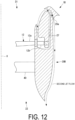
- FIG. 5 is a partially enlarged view (vertical cross-sectional view) of an F5 portion illustrated in FIG. 2 .
- FIG. 6 is a partially enlarged view of an F6 portion illustrated in FIG. 5 .
- FIG. 7 is a drawing illustrating a flow of air near a lip portion 24 illustrated in FIG. 5 .
- FIG. 8 is a perspective view, from the introduction port 21 side, of the cowl 20A.
- the connecting rim 16 that connects the compressor blade 12b and the thrust blade 12a constitutes a wall unit partitioning the housing portion 23 and a space inside the cowl 20A (the space in which the thrust blade 12a is present).
- an inner circumferential surface of the cowl 20A and an inner circumferential surface of the connecting rim 16 are connected, forming a smooth surface. That is, the inner circumferential surface of the connecting rim 16 functions as a portion of the inner circumferential surface of the cowl 20A. This makes it possible to reduce resistance to air flowing inside the cowl 20A (particularly air flowing along the inner circumferential surface of the cowl 20A).
- connecting rim 16 rotates about the axial line X together with the thrust blade 12a and the compressor blade 12b, and thus a slight gap may be provided between the connecting rim 16 and the cowl 20A in the axial line X direction. This makes it possible to smoothly rotate the connecting rim 16 with respect to the cowl 20A.
- the gap may be bent to act as a labyrinth seal. This makes it possible to suppress leakage of air from the housing portion 23 through the gap between the connecting rim 16 and the cowl 20A.
- the housing portion 23 is a bottomed space formed from the inner circumferential surface (so-called lip portion) near the introduction port 21 of the cowl 20A toward the discharge port 22 side (lower side in the drawing).
- the housing portion 23 accommodates the compressor blade 12b of the fan 10, an internal structure 25, and the stator core 30 attached to the internal structure 25.
- the internal structure 25 is connected to an inner wall of the housing portion 23 via a support column 26.
- a plurality of the support columns 26 are provided in the circumferential direction of the axial line X. However, the support columns 26 are provided separated from each other in the circumferential direction so as not to inhibit air flowing through an internal flow path 27.
- original lip portion refers to a lip portion of the cowl 20A in a case in which the housing portion 23 is not formed.
- a portion of the inner circumferential surface of the cowl 20A on and near the upper side surface of the internal structure 25 forming the flow line shape is referred to as the lip portion 24 of the cowl 20A.
- a recess 27a for receiving the compressor blade 12b, the rotor core 14, and the magnet 15 is formed on an inner circumferential side of a lower portion of the internal structure 25. Further, the stator core 30 is integrated with and fixed to the internal structure 25 facing the blade tip of the compressor blade 12b.
- the internal structure 25 defines an internal flow path 27 that is substantially U-shaped with the inner wall of the housing portion 23.
- the recess 27a is a portion of the internal flow path 27.
- the compressor blade 12b rotates at the recess 27a, thereby compressing air on a blade lower surface side, and causing air on a blade upper surface side to be sucked to the blade lower surface side and generate a flow of air in the internal flow path 27.
- the internal flow path 27 includes an opening (outlet 28a) near the lip portion 24 on the introduction portion 21 side. Further, the internal flow path 27 includes an opening (inlet 28b) near a lower portion of the lip portion 24, between the outlet 28a and the compressor blade 12b in the axial line X direction.
- the outlet 28a and the inlet 28b are formed by the upper side surface (portion corresponding to the lip portion 24) of the internal structure 25 and the cowl 20A.
- the portion of the cowl 20A corresponding to the lip portion 24 is open by the housing portion 23, and thus the internal flow path 27 is not structurally defined in a section of the portion corresponding to the lip portion 24 (section from the outlet 28a to the inlet 28b, not via the compressor blade 12b). Nevertheless, compressed air is blown from the outlet 28a at high speed by the compressor blade 12b and that air is sucked from the inlet 28b, thereby generating a fast flow of air (hereinafter referred to as "jet flow") along the upper side surface (surface including the lip portion 24) of the flow line shape of the internal structure 25 and forming an inner jet flow path 28 that is a virtual flow path.
- jet flow a fast flow of air
- the jet flow in the inner jet flow path 28 draws the surrounding air by a Coanda effect, thereby making it possible to draw, for example, the air flowing from a side surface of the cowl 20A and about to be separated at the lip portion 24 to the lip portion 24.
- the outlet 28a and the inlet 28b configured as described above are formed around an entire circumference (360°) of the cowl 20A about the axial line X, as illustrated in FIG. 1 and FIG. 8 . This makes it possible to provide the ducted fan 1A that can handle air flowing in from all directions.
- the compressor blade 12b has a blade shape different from that of the thrust blade 12a, for example, a blade shape specialized for air compression.
- the number of compressor blades 12b may differ from the number of thrust blades 12a, thereby achieving more specialized air compression.
- the ducted fan 1A includes, on the lip portion 24 of the cowl 20A, the outlet 28a configured to blow out the air flowing through the housing portion 23 by the compressor blade 12b and an inlet 28b configured to suck the air blown out from the outlet 28a, thereby making it possible to generate a jet flow along the lip portion 24 by the compressor blade 12b.
- This jet flow draws the surrounding air by the Coanda effect, thereby making it possible to draw the air about to be separated at the lip portion 24 to the lip portion 24.
- separation of the air at the lip portion 24 can be suppressed. This is useful when air flows obliquely relative to the axial line X, such as when the ducted fan 1A is inclined or when there is a crosswind.
- the connecting rim 16 forms a portion of the inner circumferential surface of the cowl 20A, thereby making it possible to partition the housing portion 23 of the cowl 20A where the compressor blade 12b is present and the space inside the cowl 20A where the thrust blade 12a is present by the connecting rim 16.
- the flow of air generated by the compressor blade 12b and the flow of air generated by the thrust blade 12a can be separated.
- outlet 28a and the inlet 28b are formed around the entire circumference of the cowl 20A, thereby making it possible to provide the ducted fan 1A that can handle crosswinds from any direction, for example.
- the ducted fan 1A is a rim drive type including the rotor core 14 provided with the magnet 15 on the outer circumferential side of the compressor blade 12b and the stator core 30 provided with a coil in the housing portion 23, thereby making it possible to cool the stator core 30, which is a heat generating component, by the flow of air generated by the compressor blade 12b.
- the outlet 28a and the inlet 28b are formed around the entire circumference of the cowl 20A about the axial line X
- the outlet 28a and the inlet 28b may be formed only in a portion of the cowl 20A in the circumferential direction, as illustrated in FIG. 10 . This makes it possible to reduce manufacturing costs compared to a case in which the outlet 28a and the inlet 28b are formed around the entire circumference of the cowl 20A.
- a portion in the circumferential direction refers to, for example, as illustrated in FIG. 11 , a portion positioned upwind when the ducted fan 1A is inclined (portion indicated by P1 in the drawing).
- the ducted fan 1A is inclined (tilted) during a transition mode from takeoff to cruising flight.
- the air flowing into the portion indicated by P1 in the drawing flows in a direction (right side in the drawing) away from the portion indicated by P1. Therefore, separation is likely to occur at the lip portion 24 upwind of the cowl 20A.
- a portion positioned downwind of the cowl 20A is inclined in a direction of receiving the wind, and thus separation is less likely to occur compared to the upwind portion indicated by P1.
- outlet 28a and the inlet 28b may be provided only on a portion of the cowl 20A positioned upwind when the ducted fan 1A is inclined.
- a ducted fan 1B of the present embodiment differs from the ducted fan 1A of the first embodiment in that a second outlet 29a is provided. Therefore, the same components are denoted by the same reference numerals and the description thereof will be omitted.
- FIG. 12 is a partially enlarged view (vertical cross-sectional view) of the F5 portion illustrated in FIG. 2 .
- FIG. 13 is a perspective view from the introduction port 21 side of a cowl 20B.
- the internal flow path 27 branches toward an outer circumferential surface (circumferential surface on an outer side) of the cowl 20B on the introduction port 21 side of the cowl 20B.
- the branched internal flow path 27 includes an opening (second outlet 29a) that communicates with the outer circumferential surface of the cowl 20B.
- the second outlet 29a opens toward the discharge port 22 side.
- Air compressed by the compressor blade 12b is blown from the second outlet 29a at high speed (refer to FIG. 13 ).
- the air forms a fast flow of air (hereinafter, referred to as "second jet flow") along the outer circumferential surface of the cowl 20B in a direction from the introduction port 21 side of the cowl 20B toward the discharge port 22 side.
- the second jet flow by the second outlet 29a can be generated by the compressor blade 12b.
- the second jet flow draws the surrounding air by the Coanda effect, making it possible to suppress the separation of air at the outer circumferential surface of the cowl 20B. Further, the flow of air along the outer circumferential surface of the cowl 20B is increased in speed by the second jet flow, making it possible to reduce the pressure that becomes a resistance component.
- an electric motor may be incorporated into the support member 40 illustrated in FIG. 2 to rotate the hub 11 about the axial line X, for example.
- a ducted fan (1A, 1B) includes a fan (10) configured to rotate about an axial line (X) to generate a flow of air, and a cowl (20A, 20B) having a cylindrical shape extending in an axial line (X) direction and surrounding the fan (10) about the axial line (X), and including an introduction port (21) configured to introduce air from a first end portion side by rotation of the fan (10), the fan (10) including a compressor blade (12b) provided on an outer circumferential side and a thrust blade (12a) provided on an inner circumferential side of the compressor blade (12b), the cowl (20A, 20B) including a housing portion (23) configured to accommodate the compressor blade (12b) in an interior thereof, an outlet (28a) configured to allow air flowing through the housing portion (23) to be blown therethrough by the compressor blade (12b), and an inlet (28b) configured to suck air blown out from the outlet (28a), the outlet (28a) being provided inwards in a
- the ducted fan (1A, 1B) includes the fan (10) configured to rotate about the axial line (X) to generate a flow of air, and the cowl (20A, 20B) having a cylindrical shape extending in the axial line (X) direction and surrounding the fan (10) about the axial line (X), and including the introduction port (21) configured to introduce air from the first end portion side by rotation of the fan (10), the fan (10) including the compressor blade (12b) provided on the outer circumferential side and the thrust blade (12a) provided on the inner circumferential side of the compressor blade (12b), the cowl (20A, 20B) including the housing portion (23) configured to accommodate the compressor blade (12b) in the interior thereof, the outlet (28a) configured to allow air flowing through the housing portion (23) to be blown therethrough by the compressor blade (12b), and the inlet (28b) configured to suck air blown out from the outlet (28a), the outlet (28a) being provided inwards in the radial direction of the cowl (20A, 20B) and
- This jet flow draws the surrounding air by a Coanda effect, thereby making it possible to draw the air about to be separated at the lip portion to the lip portion. As a result, separation of the air at the lip portion can be suppressed. This is useful when air flows obliquely relative to the axial line (X), such as when the ducted fan (1A, 1B) is inclined or when there is a crosswind.
- the compressor blade (12b) and the thrust blade (12a) are connected by a rim (16) that is annular about the axial line (X) and is configured to rotate along with the fan (10), and the rim (16) forms a portion of a surface of the cowl (20A, 20B) inwards in the radial direction.
- the compressor blade (12b) and the thrust blade (12a) are connected by the rim (16) that is annular about the axial line (X) and is configured to rotate along with the fan (10), and the rim (16) forms a portion of the surface of the cowl (20A, 20B) inwards in the radial direction, thereby making it possible to partition the housing portion (23) of the cowl (20A, 20B) where the compressor blade (12b) is present and a space inside the cowl (20A, 20B) where the thrust blade (12a) is present by the rim (16).
- the flow of air generated by the compressor blade (12b) and the flow of air generated by the thrust blade (12a) can be separated.
- the cowl (20B) includes a second outlet (29a) configured to allow air flowing through the housing portion (23) to be blown out by the compressor blade (12b), and the second outlet (29a) is provided outwards in the radial direction of the cowl (20B) and near the introduction port (21) of the cowl (20B), and thus blows out air toward a second end portion side of the cowl (20B).
- the cowl (20B) includes the second outlet (29a) configured to allow air flowing through the housing portion (23) to be blown out by the compressor blade (12b), and the second outlet (29a) is provided outwards in the radial direction of the cowl (20A, 20B) and near the introduction port (21) of the cowl (20B), and thus blows out air toward the second end portion side of the cowl (20B), thereby making it possible to generate a flow of air (hereinafter referred to as "second jet flow”) along the outer circumferential surface from near the introduction port (21) of the cowl (20B) by the compressor blade (12b).
- second jet flow a flow of air
- the second jet flow draws the surrounding air by the Coanda effect, thereby making it possible to suppress the separation of air at the outer circumferential surface of the cowl (20B). Further, the flow of air along the outer circumferential surface of the cowl (20B) is increased in speed by the second jet flow, thereby making it possible to reduce the pressure acting as a resistance component.
- the outlet (28a) and the inlet (28b) are formed around an entire circumference of the cowl (20A, 20B).
- the outlet (28a) and the inlet (28b) are formed around the entire circumference of the cowl (20A, 20B), thereby making it possible to provide the ducted fan (1A, 1B) capable of handling crosswinds from any direction, for example.
- the outlet (28a) and the inlet (28b) are partially formed in a circumferential direction of the cowl (20A, 20B).
- the outlet (28a) and the inlet (28b) are partially formed in the circumferential direction of the cowl (20A, 20B), thereby making it possible to reduce manufacturing costs compared to when the outlet (28a) and the inlet (28b) are formed around the entire circumference of the cowl (20A, 20B).
- the outlet (28a) and the inlet (28b) are provided only in a portion positioned upwind when the axial line (X) is inclined.
- the outlet (28a) and the inlet (28b) are provided only in a portion positioned upwind when the axial line (X) is inclined, thereby making it possible to provide the outlet (28a) and the inlet (28b) only in a portion where air readily separates.
- the ducted fan (1A, 1B) is a rim (16) drive type, with the fan (10) including a rotor core provided with a magnet on an outer circumferential side of the compressor blade (12b), and the cowl (20A, 20B) including a stator core provided with a coil in the housing portion (23).
- the ducted fan (1A, 1B) is a rim (16) drive type, with the fan (10) including a rotor core provided with a magnet on the outer circumferential side of the compressor blade (12b), and the cowl (20A, 20B) including a stator core provided with a coil in the housing portion (23), thereby making it possible to cool the stator core, which is a heat generating component, by the flow of air generated by the compressor blade (12b).
- a shape of the compressor blade (12b) and a shape of the thrust blade (12a) differ.
- the shape of the compressor blade (12b) and the shape of the thrust blade (12a) differ, thereby making it possible to select the shapes of the blades in accordance with an application. For example, it is possible to make only the compressor blade (12b) have a shape specialized for air compression.
- the number of the compressor blades (12b) and the number of the thrust blades (12a) differ.
- the number of compressor blades (12b) and the number of thrust blades (12a) differ, thereby making it possible to select the numbers of the blades in accordance with an application.
- an aircraft includes the above-described ducted fan (1A, 1B).
Landscapes
- Engineering & Computer Science (AREA)
- Mechanical Engineering (AREA)
- General Engineering & Computer Science (AREA)
- Aviation & Aerospace Engineering (AREA)
- Physics & Mathematics (AREA)
- Thermal Sciences (AREA)
- Structures Of Non-Positive Displacement Pumps (AREA)
Applications Claiming Priority (1)
| Application Number | Priority Date | Filing Date | Title |
|---|---|---|---|
| JP2020051196A JP7358280B2 (ja) | 2020-03-23 | 2020-03-23 | ダクテッドファン及び航空機 |
Publications (2)
| Publication Number | Publication Date |
|---|---|
| EP3885581A1 EP3885581A1 (en) | 2021-09-29 |
| EP3885581B1 true EP3885581B1 (en) | 2023-08-16 |
Family
ID=74586890
Family Applications (1)
| Application Number | Title | Priority Date | Filing Date |
|---|---|---|---|
| EP21156268.1A Active EP3885581B1 (en) | 2020-03-23 | 2021-02-10 | Ducted fan and aircraft |
Country Status (4)
| Country | Link |
|---|---|
| US (1) | US11530034B2 (enExample) |
| EP (1) | EP3885581B1 (enExample) |
| JP (1) | JP7358280B2 (enExample) |
| CN (1) | CN113428355B (enExample) |
Families Citing this family (4)
| Publication number | Priority date | Publication date | Assignee | Title |
|---|---|---|---|---|
| US11899470B2 (en) * | 2020-01-30 | 2024-02-13 | Disney Enterprises, Inc. | Airframe of a volitant body |
| US20220297827A1 (en) * | 2021-03-19 | 2022-09-22 | Embraer S.A. | An Electromagnetically-Actuated Rim Driven Hubless Fan with a Single Stage and Non-Magnetic Bearings |
| CN115303473A (zh) * | 2022-08-17 | 2022-11-08 | 北京格桑宏泰航空科技有限公司 | 一种固定翼翼尖涵道升力风扇 |
| CN121152751A (zh) * | 2024-04-16 | 2025-12-16 | 地铁航空公司 | 垂直起降航空器及其操纵方法与控制装置 |
Family Cites Families (21)
| Publication number | Priority date | Publication date | Assignee | Title |
|---|---|---|---|---|
| US3332242A (en) * | 1965-03-31 | 1967-07-25 | Gen Motors Corp | Aft fan jet engine |
| BE747870A (fr) * | 1969-03-27 | 1970-09-24 | Aerospatiale | Perfectionnements apportes aux carenages pour helices ou ventilateurs |
| GB1291943A (en) * | 1970-02-11 | 1972-10-04 | Secr Defence | Improvements in or relating to ducted fans |
| US6886776B2 (en) * | 2001-10-02 | 2005-05-03 | Karl F. Milde, Jr. | VTOL personal aircraft |
| US6843059B2 (en) * | 2002-11-19 | 2005-01-18 | General Electric Company | Combustor inlet diffuser with boundary layer blowing |
| JP4017003B2 (ja) * | 2005-09-30 | 2007-12-05 | ダイキン工業株式会社 | 遠心ファン及びこれを用いた空気調和機 |
| JP2007107435A (ja) * | 2005-10-12 | 2007-04-26 | Daikin Ind Ltd | ターボファン及びこれを用いた空気調和機 |
| JP2008057480A (ja) * | 2006-09-01 | 2008-03-13 | Daikin Ind Ltd | シュラウド付プロペラファン |
| JP4305518B2 (ja) | 2007-02-06 | 2009-07-29 | トヨタ自動車株式会社 | チップタービン駆動ファン |
| US20100140416A1 (en) | 2008-11-03 | 2010-06-10 | Ohanian Iii Osgar John | Ducted Fans with Flow Control Synthetic Jet Actuators and Methods for Ducted Fan Force and Moment Control |
| WO2010071487A1 (en) * | 2008-12-17 | 2010-06-24 | Volvo Lastvagnar Ab | Vehicle fan and vehicle comprising a fan |
| US8974177B2 (en) * | 2010-09-28 | 2015-03-10 | United Technologies Corporation | Nacelle with porous surfaces |
| NL2011128C2 (nl) | 2013-07-09 | 2015-01-12 | Eco Logical Entpr B V | Rotatie-inrichting, bijvoorbeeld een luchtverplaatser, zoals een ventilator, een propeller of een hefschroef, een waterturbine of een windturbine. |
| US9776714B2 (en) * | 2013-10-15 | 2017-10-03 | Sandor Wayne Shapery | Engine system for vertical and short take off and landing (V/STOL) aircraft |
| US10337455B2 (en) * | 2013-12-16 | 2019-07-02 | United Technologies Corporation | Fan nacelle inlet flow control |
| JP6213275B2 (ja) * | 2014-02-03 | 2017-10-18 | 株式会社デンソー | 送風機 |
| FR3032941B1 (fr) * | 2015-02-24 | 2017-03-10 | Snecma | Soufflante non carenee de turbomachine d'aeronef |
| US20170104385A1 (en) | 2015-10-08 | 2017-04-13 | Adam C. Salamon | Reduced Complexity Ring Motor Design for Propeller Driven Vehicles |
| US10926874B2 (en) | 2016-01-15 | 2021-02-23 | Aurora Flight Sciences Corporation | Hybrid propulsion vertical take-off and landing aircraft |
| US11485486B2 (en) | 2016-05-18 | 2022-11-01 | The University Of Toledo | Active flow control for ducted fans and fan-in-wing configurations |
| CN110775260B (zh) * | 2019-12-02 | 2024-06-04 | 北京玮航科技有限公司 | 涵道风扇和飞行器 |
-
2020
- 2020-03-23 JP JP2020051196A patent/JP7358280B2/ja active Active
-
2021
- 2021-02-10 EP EP21156268.1A patent/EP3885581B1/en active Active
- 2021-02-17 US US17/177,678 patent/US11530034B2/en active Active
- 2021-02-18 CN CN202110189857.2A patent/CN113428355B/zh active Active
Also Published As
| Publication number | Publication date |
|---|---|
| JP2021146981A (ja) | 2021-09-27 |
| US20210291973A1 (en) | 2021-09-23 |
| JP7358280B2 (ja) | 2023-10-10 |
| EP3885581A1 (en) | 2021-09-29 |
| CN113428355B (zh) | 2024-07-19 |
| CN113428355A (zh) | 2021-09-24 |
| US11530034B2 (en) | 2022-12-20 |
Similar Documents
| Publication | Publication Date | Title |
|---|---|---|
| EP3885581B1 (en) | Ducted fan and aircraft | |
| US7559191B2 (en) | Ducted spinner for engine cooling | |
| US11414198B2 (en) | Aircraft propulsion system | |
| US6113029A (en) | Aircraft capable of hovering and conventional flight | |
| US12246842B2 (en) | Motor-integrated fluid machine and vertical take-off and landing aircraft | |
| US12202618B2 (en) | Fan device and aircraft having the same | |
| EP3904216A1 (en) | Motor-integrated fluid machine and vertical takeoff and landing aircraft | |
| EP4247708B1 (en) | Electrically powered engine | |
| CN113978703B (zh) | 一种航空用的轮缘驱动式涵道推进器 | |
| US12024279B2 (en) | Motor-integrated fluid machine and vertical takeoff and landing aircraft | |
| US11377978B2 (en) | Device for evacuation of a ventilated lubricated chamber of a turbomachine | |
| CN113978740A (zh) | 航空用的双转子轮缘驱动型内外涵道式推进器 | |
| US12312077B2 (en) | Ducted fan device and aircraft | |
| US12187450B1 (en) | Integrated cooling structures and methods for aerial vehicle propulsion mechanisms | |
| EP3885258B1 (en) | Ducted fan device and aircraft | |
| US20240018965A1 (en) | Axial fan | |
| WO2025220308A1 (ja) | 電動ファンおよび電動垂直離着陸機 | |
| EP3878737A1 (en) | Motor-integrated fan, and vertical takeoff and landing craft |
Legal Events
| Date | Code | Title | Description |
|---|---|---|---|
| PUAI | Public reference made under article 153(3) epc to a published international application that has entered the european phase |
Free format text: ORIGINAL CODE: 0009012 |
|
| STAA | Information on the status of an ep patent application or granted ep patent |
Free format text: STATUS: THE APPLICATION HAS BEEN PUBLISHED |
|
| AK | Designated contracting states |
Kind code of ref document: A1 Designated state(s): AL AT BE BG CH CY CZ DE DK EE ES FI FR GB GR HR HU IE IS IT LI LT LU LV MC MK MT NL NO PL PT RO RS SE SI SK SM TR |
|
| STAA | Information on the status of an ep patent application or granted ep patent |
Free format text: STATUS: REQUEST FOR EXAMINATION WAS MADE |
|
| 17P | Request for examination filed |
Effective date: 20220329 |
|
| RBV | Designated contracting states (corrected) |
Designated state(s): AL AT BE BG CH CY CZ DE DK EE ES FI FR GB GR HR HU IE IS IT LI LT LU LV MC MK MT NL NO PL PT RO RS SE SI SK SM TR |
|
| GRAP | Despatch of communication of intention to grant a patent |
Free format text: ORIGINAL CODE: EPIDOSNIGR1 |
|
| STAA | Information on the status of an ep patent application or granted ep patent |
Free format text: STATUS: GRANT OF PATENT IS INTENDED |
|
| INTG | Intention to grant announced |
Effective date: 20230309 |
|
| GRAS | Grant fee paid |
Free format text: ORIGINAL CODE: EPIDOSNIGR3 |
|
| GRAA | (expected) grant |
Free format text: ORIGINAL CODE: 0009210 |
|
| STAA | Information on the status of an ep patent application or granted ep patent |
Free format text: STATUS: THE PATENT HAS BEEN GRANTED |
|
| AK | Designated contracting states |
Kind code of ref document: B1 Designated state(s): AL AT BE BG CH CY CZ DE DK EE ES FI FR GB GR HR HU IE IS IT LI LT LU LV MC MK MT NL NO PL PT RO RS SE SI SK SM TR |
|
| REG | Reference to a national code |
Ref country code: CH Ref legal event code: EP |
|
| REG | Reference to a national code |
Ref country code: DE Ref legal event code: R096 Ref document number: 602021004219 Country of ref document: DE |
|
| REG | Reference to a national code |
Ref country code: IE Ref legal event code: FG4D |
|
| REG | Reference to a national code |
Ref country code: LT Ref legal event code: MG9D |
|
| REG | Reference to a national code |
Ref country code: NL Ref legal event code: MP Effective date: 20230816 |
|
| REG | Reference to a national code |
Ref country code: AT Ref legal event code: MK05 Ref document number: 1600305 Country of ref document: AT Kind code of ref document: T Effective date: 20230816 |
|
| PG25 | Lapsed in a contracting state [announced via postgrant information from national office to epo] |
Ref country code: GR Free format text: LAPSE BECAUSE OF FAILURE TO SUBMIT A TRANSLATION OF THE DESCRIPTION OR TO PAY THE FEE WITHIN THE PRESCRIBED TIME-LIMIT Effective date: 20231117 |
|
| PG25 | Lapsed in a contracting state [announced via postgrant information from national office to epo] |
Ref country code: IS Free format text: LAPSE BECAUSE OF FAILURE TO SUBMIT A TRANSLATION OF THE DESCRIPTION OR TO PAY THE FEE WITHIN THE PRESCRIBED TIME-LIMIT Effective date: 20231216 |
|
| PG25 | Lapsed in a contracting state [announced via postgrant information from national office to epo] |
Ref country code: SE Free format text: LAPSE BECAUSE OF FAILURE TO SUBMIT A TRANSLATION OF THE DESCRIPTION OR TO PAY THE FEE WITHIN THE PRESCRIBED TIME-LIMIT Effective date: 20230816 Ref country code: RS Free format text: LAPSE BECAUSE OF FAILURE TO SUBMIT A TRANSLATION OF THE DESCRIPTION OR TO PAY THE FEE WITHIN THE PRESCRIBED TIME-LIMIT Effective date: 20230816 Ref country code: PT Free format text: LAPSE BECAUSE OF FAILURE TO SUBMIT A TRANSLATION OF THE DESCRIPTION OR TO PAY THE FEE WITHIN THE PRESCRIBED TIME-LIMIT Effective date: 20231218 Ref country code: NO Free format text: LAPSE BECAUSE OF FAILURE TO SUBMIT A TRANSLATION OF THE DESCRIPTION OR TO PAY THE FEE WITHIN THE PRESCRIBED TIME-LIMIT Effective date: 20231116 Ref country code: NL Free format text: LAPSE BECAUSE OF FAILURE TO SUBMIT A TRANSLATION OF THE DESCRIPTION OR TO PAY THE FEE WITHIN THE PRESCRIBED TIME-LIMIT Effective date: 20230816 Ref country code: LV Free format text: LAPSE BECAUSE OF FAILURE TO SUBMIT A TRANSLATION OF THE DESCRIPTION OR TO PAY THE FEE WITHIN THE PRESCRIBED TIME-LIMIT Effective date: 20230816 Ref country code: LT Free format text: LAPSE BECAUSE OF FAILURE TO SUBMIT A TRANSLATION OF THE DESCRIPTION OR TO PAY THE FEE WITHIN THE PRESCRIBED TIME-LIMIT Effective date: 20230816 Ref country code: IS Free format text: LAPSE BECAUSE OF FAILURE TO SUBMIT A TRANSLATION OF THE DESCRIPTION OR TO PAY THE FEE WITHIN THE PRESCRIBED TIME-LIMIT Effective date: 20231216 Ref country code: HR Free format text: LAPSE BECAUSE OF FAILURE TO SUBMIT A TRANSLATION OF THE DESCRIPTION OR TO PAY THE FEE WITHIN THE PRESCRIBED TIME-LIMIT Effective date: 20230816 Ref country code: GR Free format text: LAPSE BECAUSE OF FAILURE TO SUBMIT A TRANSLATION OF THE DESCRIPTION OR TO PAY THE FEE WITHIN THE PRESCRIBED TIME-LIMIT Effective date: 20231117 Ref country code: FI Free format text: LAPSE BECAUSE OF FAILURE TO SUBMIT A TRANSLATION OF THE DESCRIPTION OR TO PAY THE FEE WITHIN THE PRESCRIBED TIME-LIMIT Effective date: 20230816 Ref country code: AT Free format text: LAPSE BECAUSE OF FAILURE TO SUBMIT A TRANSLATION OF THE DESCRIPTION OR TO PAY THE FEE WITHIN THE PRESCRIBED TIME-LIMIT Effective date: 20230816 |
|
| PG25 | Lapsed in a contracting state [announced via postgrant information from national office to epo] |
Ref country code: PL Free format text: LAPSE BECAUSE OF FAILURE TO SUBMIT A TRANSLATION OF THE DESCRIPTION OR TO PAY THE FEE WITHIN THE PRESCRIBED TIME-LIMIT Effective date: 20230816 |
|
| PG25 | Lapsed in a contracting state [announced via postgrant information from national office to epo] |
Ref country code: ES Free format text: LAPSE BECAUSE OF FAILURE TO SUBMIT A TRANSLATION OF THE DESCRIPTION OR TO PAY THE FEE WITHIN THE PRESCRIBED TIME-LIMIT Effective date: 20230816 |
|
| PG25 | Lapsed in a contracting state [announced via postgrant information from national office to epo] |
Ref country code: SM Free format text: LAPSE BECAUSE OF FAILURE TO SUBMIT A TRANSLATION OF THE DESCRIPTION OR TO PAY THE FEE WITHIN THE PRESCRIBED TIME-LIMIT Effective date: 20230816 Ref country code: RO Free format text: LAPSE BECAUSE OF FAILURE TO SUBMIT A TRANSLATION OF THE DESCRIPTION OR TO PAY THE FEE WITHIN THE PRESCRIBED TIME-LIMIT Effective date: 20230816 Ref country code: ES Free format text: LAPSE BECAUSE OF FAILURE TO SUBMIT A TRANSLATION OF THE DESCRIPTION OR TO PAY THE FEE WITHIN THE PRESCRIBED TIME-LIMIT Effective date: 20230816 Ref country code: EE Free format text: LAPSE BECAUSE OF FAILURE TO SUBMIT A TRANSLATION OF THE DESCRIPTION OR TO PAY THE FEE WITHIN THE PRESCRIBED TIME-LIMIT Effective date: 20230816 Ref country code: DK Free format text: LAPSE BECAUSE OF FAILURE TO SUBMIT A TRANSLATION OF THE DESCRIPTION OR TO PAY THE FEE WITHIN THE PRESCRIBED TIME-LIMIT Effective date: 20230816 Ref country code: CZ Free format text: LAPSE BECAUSE OF FAILURE TO SUBMIT A TRANSLATION OF THE DESCRIPTION OR TO PAY THE FEE WITHIN THE PRESCRIBED TIME-LIMIT Effective date: 20230816 Ref country code: SK Free format text: LAPSE BECAUSE OF FAILURE TO SUBMIT A TRANSLATION OF THE DESCRIPTION OR TO PAY THE FEE WITHIN THE PRESCRIBED TIME-LIMIT Effective date: 20230816 |
|
| REG | Reference to a national code |
Ref country code: DE Ref legal event code: R097 Ref document number: 602021004219 Country of ref document: DE |
|
| PLBE | No opposition filed within time limit |
Free format text: ORIGINAL CODE: 0009261 |
|
| STAA | Information on the status of an ep patent application or granted ep patent |
Free format text: STATUS: NO OPPOSITION FILED WITHIN TIME LIMIT |
|
| 26N | No opposition filed |
Effective date: 20240517 |
|
| PG25 | Lapsed in a contracting state [announced via postgrant information from national office to epo] |
Ref country code: IT Free format text: LAPSE BECAUSE OF FAILURE TO SUBMIT A TRANSLATION OF THE DESCRIPTION OR TO PAY THE FEE WITHIN THE PRESCRIBED TIME-LIMIT Effective date: 20230816 Ref country code: SI Free format text: LAPSE BECAUSE OF FAILURE TO SUBMIT A TRANSLATION OF THE DESCRIPTION OR TO PAY THE FEE WITHIN THE PRESCRIBED TIME-LIMIT Effective date: 20230816 |
|
| PG25 | Lapsed in a contracting state [announced via postgrant information from national office to epo] |
Ref country code: MC Free format text: LAPSE BECAUSE OF FAILURE TO SUBMIT A TRANSLATION OF THE DESCRIPTION OR TO PAY THE FEE WITHIN THE PRESCRIBED TIME-LIMIT Effective date: 20230816 |
|
| REG | Reference to a national code |
Ref country code: CH Ref legal event code: PL |
|
| PG25 | Lapsed in a contracting state [announced via postgrant information from national office to epo] |
Ref country code: LU Free format text: LAPSE BECAUSE OF NON-PAYMENT OF DUE FEES Effective date: 20240210 |
|
| PG25 | Lapsed in a contracting state [announced via postgrant information from national office to epo] |
Ref country code: CH Free format text: LAPSE BECAUSE OF NON-PAYMENT OF DUE FEES Effective date: 20240229 |
|
| PG25 | Lapsed in a contracting state [announced via postgrant information from national office to epo] |
Ref country code: LU Free format text: LAPSE BECAUSE OF NON-PAYMENT OF DUE FEES Effective date: 20240210 Ref country code: CH Free format text: LAPSE BECAUSE OF NON-PAYMENT OF DUE FEES Effective date: 20240229 |
|
| PG25 | Lapsed in a contracting state [announced via postgrant information from national office to epo] |
Ref country code: BG Free format text: LAPSE BECAUSE OF FAILURE TO SUBMIT A TRANSLATION OF THE DESCRIPTION OR TO PAY THE FEE WITHIN THE PRESCRIBED TIME-LIMIT Effective date: 20230816 |
|
| PG25 | Lapsed in a contracting state [announced via postgrant information from national office to epo] |
Ref country code: BG Free format text: LAPSE BECAUSE OF FAILURE TO SUBMIT A TRANSLATION OF THE DESCRIPTION OR TO PAY THE FEE WITHIN THE PRESCRIBED TIME-LIMIT Effective date: 20230816 |
|
| REG | Reference to a national code |
Ref country code: BE Ref legal event code: MM Effective date: 20240229 |
|
| PG25 | Lapsed in a contracting state [announced via postgrant information from national office to epo] |
Ref country code: BE Free format text: LAPSE BECAUSE OF NON-PAYMENT OF DUE FEES Effective date: 20240229 |
|
| PGFP | Annual fee paid to national office [announced via postgrant information from national office to epo] |
Ref country code: GB Payment date: 20241227 Year of fee payment: 5 |
|
| PG25 | Lapsed in a contracting state [announced via postgrant information from national office to epo] |
Ref country code: FR Free format text: LAPSE BECAUSE OF NON-PAYMENT OF DUE FEES Effective date: 20240229 |
|
| PG25 | Lapsed in a contracting state [announced via postgrant information from national office to epo] |
Ref country code: IE Free format text: LAPSE BECAUSE OF NON-PAYMENT OF DUE FEES Effective date: 20240210 |
|
| PG25 | Lapsed in a contracting state [announced via postgrant information from national office to epo] |
Ref country code: IE Free format text: LAPSE BECAUSE OF NON-PAYMENT OF DUE FEES Effective date: 20240210 Ref country code: FR Free format text: LAPSE BECAUSE OF NON-PAYMENT OF DUE FEES Effective date: 20240229 Ref country code: BE Free format text: LAPSE BECAUSE OF NON-PAYMENT OF DUE FEES Effective date: 20240229 |
|
| PGFP | Annual fee paid to national office [announced via postgrant information from national office to epo] |
Ref country code: DE Payment date: 20241231 Year of fee payment: 5 |
|
| PG25 | Lapsed in a contracting state [announced via postgrant information from national office to epo] |
Ref country code: CY Free format text: LAPSE BECAUSE OF FAILURE TO SUBMIT A TRANSLATION OF THE DESCRIPTION OR TO PAY THE FEE WITHIN THE PRESCRIBED TIME-LIMIT; INVALID AB INITIO Effective date: 20210210 |
|
| PG25 | Lapsed in a contracting state [announced via postgrant information from national office to epo] |
Ref country code: HU Free format text: LAPSE BECAUSE OF FAILURE TO SUBMIT A TRANSLATION OF THE DESCRIPTION OR TO PAY THE FEE WITHIN THE PRESCRIBED TIME-LIMIT; INVALID AB INITIO Effective date: 20210210 |
|
| PG25 | Lapsed in a contracting state [announced via postgrant information from national office to epo] |
Ref country code: TR Free format text: LAPSE BECAUSE OF FAILURE TO SUBMIT A TRANSLATION OF THE DESCRIPTION OR TO PAY THE FEE WITHIN THE PRESCRIBED TIME-LIMIT Effective date: 20230816 |