EP3885259A1 - Unmanned aerial vehicle system, control device and control method - Google Patents
Unmanned aerial vehicle system, control device and control method Download PDFInfo
- Publication number
- EP3885259A1 EP3885259A1 EP19952908.2A EP19952908A EP3885259A1 EP 3885259 A1 EP3885259 A1 EP 3885259A1 EP 19952908 A EP19952908 A EP 19952908A EP 3885259 A1 EP3885259 A1 EP 3885259A1
- Authority
- EP
- European Patent Office
- Prior art keywords
- unmanned aircraft
- hoisting
- linear member
- package
- positional relationship
- Prior art date
- Legal status (The legal status is an assumption and is not a legal conclusion. Google has not performed a legal analysis and makes no representation as to the accuracy of the status listed.)
- Granted
Links
Images



Classifications
-
- B—PERFORMING OPERATIONS; TRANSPORTING
- B64—AIRCRAFT; AVIATION; COSMONAUTICS
- B64D—EQUIPMENT FOR FITTING IN OR TO AIRCRAFT; FLIGHT SUITS; PARACHUTES; ARRANGEMENT OR MOUNTING OF POWER PLANTS OR PROPULSION TRANSMISSIONS IN AIRCRAFT
- B64D1/00—Dropping, ejecting, releasing or receiving articles, liquids, or the like, in flight
- B64D1/22—Taking-up articles from earth's surface
-
- B—PERFORMING OPERATIONS; TRANSPORTING
- B64—AIRCRAFT; AVIATION; COSMONAUTICS
- B64D—EQUIPMENT FOR FITTING IN OR TO AIRCRAFT; FLIGHT SUITS; PARACHUTES; ARRANGEMENT OR MOUNTING OF POWER PLANTS OR PROPULSION TRANSMISSIONS IN AIRCRAFT
- B64D1/00—Dropping, ejecting, releasing or receiving articles, liquids, or the like, in flight
- B64D1/02—Dropping, ejecting, or releasing articles
-
- B—PERFORMING OPERATIONS; TRANSPORTING
- B64—AIRCRAFT; AVIATION; COSMONAUTICS
- B64D—EQUIPMENT FOR FITTING IN OR TO AIRCRAFT; FLIGHT SUITS; PARACHUTES; ARRANGEMENT OR MOUNTING OF POWER PLANTS OR PROPULSION TRANSMISSIONS IN AIRCRAFT
- B64D1/00—Dropping, ejecting, releasing or receiving articles, liquids, or the like, in flight
- B64D1/02—Dropping, ejecting, or releasing articles
- B64D1/08—Dropping, ejecting, or releasing articles the articles being load-carrying devices
- B64D1/12—Releasing
-
- B—PERFORMING OPERATIONS; TRANSPORTING
- B66—HOISTING; LIFTING; HAULING
- B66D—CAPSTANS; WINCHES; TACKLES, e.g. PULLEY BLOCKS; HOISTS
- B66D1/00—Rope, cable, or chain winding mechanisms; Capstans
- B66D1/28—Other constructional details
- B66D1/40—Control devices
- B66D1/48—Control devices automatic
- B66D1/485—Control devices automatic electrical
-
- B—PERFORMING OPERATIONS; TRANSPORTING
- B64—AIRCRAFT; AVIATION; COSMONAUTICS
- B64U—UNMANNED AERIAL VEHICLES [UAV]; EQUIPMENT THEREFOR
- B64U10/00—Type of UAV
- B64U10/10—Rotorcrafts
- B64U10/13—Flying platforms
-
- B—PERFORMING OPERATIONS; TRANSPORTING
- B64—AIRCRAFT; AVIATION; COSMONAUTICS
- B64U—UNMANNED AERIAL VEHICLES [UAV]; EQUIPMENT THEREFOR
- B64U2101/00—UAVs specially adapted for particular uses or applications
- B64U2101/30—UAVs specially adapted for particular uses or applications for imaging, photography or videography
-
- B—PERFORMING OPERATIONS; TRANSPORTING
- B64—AIRCRAFT; AVIATION; COSMONAUTICS
- B64U—UNMANNED AERIAL VEHICLES [UAV]; EQUIPMENT THEREFOR
- B64U2101/00—UAVs specially adapted for particular uses or applications
- B64U2101/60—UAVs specially adapted for particular uses or applications for transporting passengers; for transporting goods other than weapons
- B64U2101/64—UAVs specially adapted for particular uses or applications for transporting passengers; for transporting goods other than weapons for parcel delivery or retrieval
- B64U2101/66—UAVs specially adapted for particular uses or applications for transporting passengers; for transporting goods other than weapons for parcel delivery or retrieval for retrieving parcels
-
- B—PERFORMING OPERATIONS; TRANSPORTING
- B64—AIRCRAFT; AVIATION; COSMONAUTICS
- B64U—UNMANNED AERIAL VEHICLES [UAV]; EQUIPMENT THEREFOR
- B64U2101/00—UAVs specially adapted for particular uses or applications
- B64U2101/60—UAVs specially adapted for particular uses or applications for transporting passengers; for transporting goods other than weapons
- B64U2101/67—UAVs specially adapted for particular uses or applications for transporting passengers; for transporting goods other than weapons the UAVs comprising tethers for lowering the goods
-
- B—PERFORMING OPERATIONS; TRANSPORTING
- B64—AIRCRAFT; AVIATION; COSMONAUTICS
- B64U—UNMANNED AERIAL VEHICLES [UAV]; EQUIPMENT THEREFOR
- B64U2201/00—UAVs characterised by their flight controls
-
- B—PERFORMING OPERATIONS; TRANSPORTING
- B64—AIRCRAFT; AVIATION; COSMONAUTICS
- B64U—UNMANNED AERIAL VEHICLES [UAV]; EQUIPMENT THEREFOR
- B64U2201/00—UAVs characterised by their flight controls
- B64U2201/20—Remote controls
-
- B—PERFORMING OPERATIONS; TRANSPORTING
- B64—AIRCRAFT; AVIATION; COSMONAUTICS
- B64U—UNMANNED AERIAL VEHICLES [UAV]; EQUIPMENT THEREFOR
- B64U50/00—Propulsion; Power supply
- B64U50/10—Propulsion
- B64U50/19—Propulsion using electrically powered motors
Definitions
- the present invention relates to an unmanned aircraft system, a control device and a control method.
- the present invention has an object of providing an unmanned aircraft system, a control device and a control method which can anchor a package to a linear member more easily.
- the unmanned aircraft 2 is not particularly limited so long as capable of flying unmanned; however, the unmanned aircraft 2 of the present embodiment illustrated is an unmanned rotorcraft having a plurality of rotor blades 21. In addition, the unmanned aircraft 2 further has a battery, etc. (not illustrated) which supplies electric power for driving the rotor blades 21.
- the linear member 31 may join the leading end part thereof to the package T, and may have a connecting member 32 for connecting the package T to the leading end.
- the connecting member 32 provided to the leading end of the linear member 31 may be separable from the package by a person manipulating a hook, shackle or the like, for example, and may have a detach mechanism which can detach the package T unmanned.
- the hoisting mechanism 3 has a measurement unit 33.
- the measurement unit 33 for example, is configured by a rotation detection sensor, and measures the feed out length of the linear member 31.
- the measurement unit 33 outputs to the control device 6 a measured feed out length of the linear member 31.
- the measurement unit 33 may use another method which can measure the feed out length of the linear member 31.
- the measurement unit 33 may be made a configuration in which the control device 6 has a meter which calculates the feed out length based on the rotation amount.
- FIGS. 3A and 3B are a schematic diagram showing the hoisting control of the linear member 31 of the unmanned aircraft 2. It should be noted that, in FIGS. 3A and 3B , configurations such as of the drop-preventing mechanism 4 are omitted.
- the hoisting control unit 62 in a state in which the unmanned aircraft 2 has touched down, the hoisting control unit 62 establishes a state releasing the linear member 31 by the hoisting mechanism 3, and feeding out the linear member 31. Then, the package T is connected to the linear member 31 in a state in which the unmanned aircraft 2 has touched down, and the leading end of the linear member 31 is distanced from the main portion of the unmanned aircraft 2.
- the flight control unit 61 makes the unmanned aircraft 2 take off in a state in which the package T anchored to the linear member 31 is arranged on the ground G.
- the imaging unit 5 captures an image including the package T as positional relationship calculation information for calculating the positional information.
- the imaging unit 5 detects an image as the positional relationship calculation information.
- the positional relationship calculation unit 63 calculates the positional relationship between the unmanned aircraft 2 and package T based on an image including the package T captured by the imaging unit 5.
- the hoisting control unit 62 determines as being a state enabling hoisting of the linear member 31, in a case of the distance between the unmanned aircraft 2 and package T being sufficiently separate, and the central coordinate of the package T being within a fixed range from the central coordinate of the unmanned aircraft 2.
- the central coordinate of the unmanned aircraft 2 is detected by the GPS, for example.
- the hoisting control unit 62 can thereby determine as being a state enabling hoisting of the linear member 31.
- the comparison processing of the central coordinate of the package T and the central coordinate of the unmanned aircraft 2 for determining the hoisting state is carried out using two-dimensional coordinates in the horizontal direction. It should be noted that it may be processing which processes the central coordinate of the unmanned aircraft 2 as three-dimensional coordinates, and uses in the comparison only a horizontal portion of the coordinates when processing to determine whether or not being within the aforementioned fixed range.
- the measurement unit 33 measures the feed out length of the linear member 31, and the altimeter 7 measures the altitude of the unmanned aircraft, thereby detecting the positional relationship calculation information.
- the positional relationship calculation unit 63 calculates the positional relationship based on the feed out length of the linear member 31 measured by the measurement unit 33 and the altitude of the unmanned aircraft 2 measured by the altimeter 7.
- the flight control unit 61 controls flight of the unmanned aircraft 2 so as to rise and move to a position almost directly below the package T, until the hoisting condition is satisfied. Then, after satisfying the hoisting condition and hoisting the linear member 31, the flight control unit 61 controls the unmanned aircraft 2 so as to fly towards the destination.
- the unmanned aircraft system 1 may use a combination of the configuration made using the imaging unit 5 as the aforementioned detector, and the configuration made using the altimeter 7 and measurement unit 33 as detectors.
- Step S4 the hoisting control unit 62 determines whether the calculated positional relationship satisfies the hoisting condition. In the case of satisfying the aforementioned hoisting condition (YES), the processing advances to Step S5, and in the case of not satisfying the hoisting condition, the processing returns to Step S3.
- Step S5 the hoisting control unit 62 causes the linear member 31 to be hoisted to the hoisting mechanism 3.
- the hoisting control unit 62 after sufficiently hoisting the linear member 31 until the package T approaches within a fixed range from the unmanned aircraft 2, controls the mobile support 41 of the drop-preventing mechanism 4, and transitions to a state preventing dropping of the package T.
- the retaining device 10 fixes the package T in a state in which the unmanned aircraft 2 has landed on the ground G.
- the flight control unit 61 causes the unmanned aircraft 2 to land in a state fixing the package T by the retaining device 10.
- the hoisting control unit 62 feeds out the linear member 31 in a length according to the altitude of the unmanned aircraft 2 by the hoisting mechanism 3. Then, as shown in FIG. 6B , in the case of the altitude of the unmanned aircraft 2 being higher than in FIG. 6A , the hoisting control unit 62 further feeds out the linear member 31 by the hoisting mechanism 3.
- the unmanned aircraft system (1) includes: the unmanned aircraft (2) equipped with the hoisting mechanism capable of feeding out and hoisting the linear member (31); the flight control unit (61) which makes the unmanned aircraft (2) take off in a state in which the package (T) anchored to the linear member (31) is arranged on the ground surface (G); and the hoisting control unit (62) which hoists the linear member (31) by the hoisting mechanism (3) after the unmanned aircraft (2) takes off, in the case of the hoisting condition indicating a state enabling hoisting of the linear member (31) being satisfied.
- the hoisting control unit (62) releases the linear member (31) to allow pulling out from the hoisting mechanism (3), until the hoisting condition is satisfied after the unmanned aircraft (2) takes off.
- the unmanned aircraft system (1) can thereby cause the unmanned aircraft (2) to fly without changing the position and orientation of the package (T) anchored to the linear member (31).
- the unmanned aircraft system (1) further includes the altimeter (7) which measures the altitude of the unmanned aircraft (2), and the hoisting control unit (62) feeds out the linear member by the hoisting mechanism (3) according to the altitude of the unmanned aircraft (2) measured by the altimeter (7).
- the unmanned aircraft system (1) can thereby fly without changing the position and orientation of the package (T) anchored to the linear member (31), and hoist the linear member (31).
Landscapes
- Engineering & Computer Science (AREA)
- Aviation & Aerospace Engineering (AREA)
- Mechanical Engineering (AREA)
- Control Of Position, Course, Altitude, Or Attitude Of Moving Bodies (AREA)
Abstract
Description
- The present invention relates to an unmanned aircraft system, a control device and a control method.
- It is being considered to transport cargo using an aircraft which can fly unmanned such as a so-called drone. For example, supplementing a box or the like accommodating cargo to an aircraft, and delivering the cargo by releasing the box in a state of the aircraft landed has been carried out. In this case, as the delivery location of cargo, a flat location having at least a certain area in which the aircraft can land becomes necessary.
- Therefore, as disclosed in
Patent Document 1 described below, for example, it is also being considered to provide a hoisting mechanism (winch) capable of feeding out and winding up a linear member such as wire or cable to the aircraft, retain a package (can include cargo and a container accommodating cargo) at the leading end of the linear member, and deliver cargo while remaining in the air, without the aircraft landing. According to such a method, so long as there is a relatively small space which can place the package, it is possible to deliver the cargo. In addition, according to the device configuration, there are also cases where it is possible to deliver a package in a shorter time by feeding out the linear member than landing the aircraft. - Patent Document 1:
Japanese Unexamined Patent Application, Publication No. 2016-88675 - In the technology of transporting packages anchored to a linear member such as that disclosed in
Patent Document 1 by an unmanned aircraft, in order to improve the delivery efficiency, it has been sought to anchor a package to a linear member more easily. - The present invention has an object of providing an unmanned aircraft system, a control device and a control method which can anchor a package to a linear member more easily.
- An unmanned aircraft system according to an aspect of the present invention includes: an unmanned aircraft including a hoisting mechanism capable of feeding out and hoisting a linear member; a flight control unit which causes the unmanned aircraft to take off in a state in which a package anchored to the linear member is arranged on a ground surface; and a hoisting control unit which causes the linear member to be hoisted by the hoisting mechanism, after the unmanned aircraft has taken off, in a case of a hoisting condition indicating a state enabling hoisting of the linear member being satisfied. A control device for an unmanned aircraft according to another aspect of the present invention includes: a flight control unit which causes an unmanned aircraft to take off in a state in which a package anchored to a linear member is arranged on a ground surface; and a hoisting control unit which causes the linear member to be hoisted by a hoisting mechanism, after the unmanned aircraft has taken off, in a case of a hoisting condition indicating a state enabling hoisting of the linear member being satisfied.
- A control method for an unmanned aircraft according to yet another aspect of the present invention includes the steps of: causing an unmanned aircraft to take off in a state in which a package anchored to a linear member is arranged on a ground surface; and hoisting the linear member by a hoisting mechanism, after the unmanned aircraft has taken off, in a case of a hoisting condition indicating a state enabling hoisting of the linear member being satisfied.
- According to the present invention, it is possible to provide an unmanned aircraft system, a control device and a control method which can more easily anchor a package to a linear member.
-
-
FIG. 1 is a schematic diagram showing the configuration of an unmanned aircraft system according to an embodiment of the present invention; -
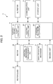
FIG. 2 is a block diagram showing a functional configuration of an unmanned aircraft system; -
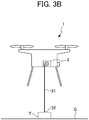
FIGS. 3A and3B are a schematic diagram showing hoisting control of a linear member of the unmanned aircraft system; -
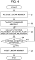
FIG. 4 is a flowchart showing processing of a control device of the unmanned aircraft system; -
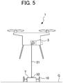
FIG. 5 is a schematic diagram showing the configuration of an unmanned aircraft system of a first modified example; and -
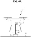
FIGS. 6A and6B are a schematic diagram showing the configuration of an unmanned aircraft system of a second modified example. - Hereinafter, an unrestrictive illustrative embodiment of the present invention will be explained while referencing the drawings.
FIG. 1 is a schematic diagram showing the configuration of anunmanned aircraft system 1 according to an embodiment of the present invention. Theunmanned aircraft system 1 transports a package T unmanned, by flying in a state retaining the package T. - As shown in
FIG. 1 , theunmanned aircraft system 1 includes: anunmanned aircraft 2, ahoisting mechanism 3, a drop-preventing mechanism 4, animaging unit 5, and acontrol device 6. - The
unmanned aircraft 2 is not particularly limited so long as capable of flying unmanned; however, theunmanned aircraft 2 of the present embodiment illustrated is an unmanned rotorcraft having a plurality ofrotor blades 21. In addition, theunmanned aircraft 2 further has a battery, etc. (not illustrated) which supplies electric power for driving therotor blades 21. - The
hoisting mechanism 3 is provided to theunmanned aircraft 2, and is able to feed out and hoist thelinear member 31 capable of connecting the package T to the leading end. Thehoisting mechanism 3 is a winch which can hoist thelinear member 31 by way of a motor (not illustrated). As thelinear member 31 hoisted by thehoisting mechanism 3, for example, a member having flexibility such as a rope or wire can be used. - The
linear member 31 may join the leading end part thereof to the package T, and may have a connectingmember 32 for connecting the package T to the leading end. The connectingmember 32 provided to the leading end of thelinear member 31 may be separable from the package by a person manipulating a hook, shackle or the like, for example, and may have a detach mechanism which can detach the package T unmanned. - The mechanism for connecting of the connecting
member 32 may be a mechanism which holds mechanically using frictional force, or may be made using the magnetic force of an electromagnet or the like. - The drop-preventing
mechanism 4 is configured so as to be able to prevent dropping of the package T by holding the package T even if the connection with thelinear member 31 was released, in a state in which thehoisting mechanism 3 brings the package T to within a fixed range from theunmanned aircraft 2 by hoisting thelinear member 31. - The
mobile support 41 is configured so as to support at least the bottom of the package T in a state supporting the package T. In addition, themobile support 41 may be configured so as to restrict the movement to the side of the package T by abutting the lateral surface of the package T, and may also serve as a member holding the package T to be immobile while flying. - The
imaging unit 5, for example, is configured by a digital camera which can capture still images and moving images. Theimaging unit 5 is installed to a lateral surface of theunmanned aircraft 2, and captures still images and moving images in the direction below theunmanned aircraft 2. - The
control device 6, for example, can be realized by introducing a predetermined program to a computer device equipped with a CPU, memory, etc. Thecontrol device 6 may communicate with an external server (remote control device) arranged at a position distanced from theunmanned aircraft 2 via a communication unit. In addition, theunmanned aircraft 2 may be configured so as to be able to return to a predetermined delivery base or the like, after delivering the package T to the receiver by flying to the destination independently according to the control of thecontrol device 6, even if there is no instruction from the remote control device. - The
altimeter 7, for example, is a barometric pressure meter, and measures the altitude of theunmanned aircraft 2. It should be noted that thealtimeter 7 may measure the altitude by another method. - Next, operation of the
unmanned aircraft system 1 according to the present embodiment will be explained by referencingFIGS. 2 and3 .FIG. 2 is a block diagram showing the functional configuration of theunmanned aircraft system 1. - As shown in
FIG. 2 , theunmanned aircraft system 1 includes:rotor blades 21, amotor 22,hoisting mechanism 3, drop-preventing mechanism 4,imaging unit 5,control device 6,altimeter 7,communication unit 8, andstorage unit 9. - The plurality of
rotor blades 21 andmotor 22 provided to each of the plurality ofrotor blades 21 make theunmanned aircraft system 1 fly by the rotation being controlled by thecontrol device 6. - The
hoisting mechanism 3 has ameasurement unit 33. Themeasurement unit 33, for example, is configured by a rotation detection sensor, and measures the feed out length of thelinear member 31. Themeasurement unit 33 outputs to the control device 6 a measured feed out length of thelinear member 31. Themeasurement unit 33 may use another method which can measure the feed out length of thelinear member 31. For example, themeasurement unit 33 may be made a configuration in which thecontrol device 6 has a meter which calculates the feed out length based on the rotation amount. - The drop-
preventing mechanism 4 operates in accordance with the control of thecontrol device 6. For example, themobile support 41 of the drop-preventingmechanism 4 transitions between a state preventing dropping of the package T (and falling), and a state enabling dropping (and falling) of the package T, in accordance with the control of thecontrol device 6. - The
imaging unit 5 functions as detector, and detects the positional relationship calculation information by capturing images of the package T. Theimaging unit 5 outputs the captured image to thecontrol device 6. - The
control device 6 is a processor such as a CPU (Central Processing Unit), and functions as aflight control unit 61, hoistcontrol unit 62 and positionalrelationship calculation unit 63, by executing programs stored in the storage unit 23. - The
altimeter 7 measures the altitude of theunmanned aircraft 2, and outputs the measurement results to thecontrol device 6. Thecommunication unit 8 performs wireless communication with a remote control device for remotely operating theunmanned aircraft 2, and other unmanned aircraft, etc. - The
storage unit 9 is a storage device such as ROM (Read Only Member) and RAM (Random Access Memory) storing the OS (Operating System), application programs, etc., and a hard disk drive or SSD (Solid State Drive) which stores various other information. - It should be noted that the
unmanned aircraft 2 may include various sensors such as a gyro sensor, acceleration sensor, ultrasonic sensor, magnetic direction sensor and GPS (Global Positioning System), in addition to the aforementioned configuration. For example, theunmanned aircraft 2 detects positional information of theunmanned aircraft 2 by GPS. -
FIGS. 3A and3B are a schematic diagram showing the hoisting control of thelinear member 31 of theunmanned aircraft 2. It should be noted that, inFIGS. 3A and3B , configurations such as of the drop-preventingmechanism 4 are omitted. As shown inFIG. 3A , in a state in which theunmanned aircraft 2 has touched down, the hoistingcontrol unit 62 establishes a state releasing thelinear member 31 by thehoisting mechanism 3, and feeding out thelinear member 31. Then, the package T is connected to thelinear member 31 in a state in which theunmanned aircraft 2 has touched down, and the leading end of thelinear member 31 is distanced from the main portion of theunmanned aircraft 2. - By raising the
unmanned aircraft 2 in a state releasing thelinear member 31, the package T is hardly pulled by thelinear member 31, and theunmanned aircraft system 1 can suppress the shock on the package T (for example, the package T falling, being dragged, etc.). - It should be noted that the release of the
linear member 31, for example, is a state such that thelinear member 31 is pulled out by the tensile force thereof, when thehoisting mechanism 3 releases the fixation of rotation of the winding cylinder which is winding thelinear member 31, and thelinear member 31 is drawn. In other words, it is state allowing thelinear member 31 to be pulled out from thehoisting mechanism 3. - The
flight control unit 61 makes theunmanned aircraft 2 take off in a state in which the package T anchored to thelinear member 31 is arranged on the ground G. - Subsequently, as shown in
FIG. 3B , after theunmanned aircraft 2 has taken off, when theunmanned aircraft 2 is positioned almost directly above the package T, the hoistingcontrol unit 62 causes thelinear member 31 to be hoisted by way of thehoisting mechanism 3. In other words, the hoistingcontrol unit 62 causes thelinear member 31 to be hoisted by thehoisting mechanism 3, after theunmanned aircraft 2 has taken off, in a case of the hoisting condition indicating a state enabling hoisting of thelinear member 31 being satisfied. - In addition, the hoisting
control unit 62 feeds out thelinear member 31 by thehoisting mechanism 3, until theunmanned aircraft 2 takes off, and then the hoisting condition is satisfied. Theunmanned aircraft 2 can thereby fly without changing the position and orientation of the package T anchored to thelinear member 31. - In the
hoisting control unit 62, the hoisting condition includes being a state in which the positional relationship calculated by the positionalrelationship calculation unit 63 allows for hoisting thelinear member 31. Herein, state enabling hoisting may be a position determined as being directly above the package T by the hoistingcontrol unit 62. Then, the positionalrelationship calculation unit 63 calculates the positional relationship between theunmanned aircraft 2 and package T, based on the positional relationship calculation information detected by theimaging unit 5,altimeter 7 andmeasurement unit 33 serving as detectors. - For example, in the case of the detector being the
imaging unit 5, theimaging unit 5 captures an image including the package T as positional relationship calculation information for calculating the positional information. In other words, theimaging unit 5 detects an image as the positional relationship calculation information. The positionalrelationship calculation unit 63 calculates the positional relationship between theunmanned aircraft 2 and package T based on an image including the package T captured by theimaging unit 5. - The positional
information calculation unit 63 identifies the package T from the image including the package T, and calculates the external form and size of the identified package T. The positionalrelationship calculation unit 63 calculates the distance between theunmanned aircraft 2 and package T, by comparing between the external form and size of the package T stored in advance in thestorage unit 9, and the external form and size of the package T calculated from the image including the package T. In addition, the positionalrelationship calculation unit 63 calculates the central coordinate of the package T from the image including the package T. - In this case, the hoisting
control unit 62 determines whether the position of theunmanned aircraft 2 is in a state enabling hoisting of the linear member 31 (positional relationship between package T andunmanned aircraft 2 is a state enabling hoisting of the linear member 31), based on the distance between theunmanned aircraft 2 and package T and the central coordinate of the package T calculated by the positionalrelationship calculation unit 63. - For example, the hoisting
control unit 62 determines as being a state enabling hoisting of thelinear member 31, in a case of the distance between theunmanned aircraft 2 and package T being sufficiently separate, and the central coordinate of the package T being within a fixed range from the central coordinate of theunmanned aircraft 2. Herein, the central coordinate of theunmanned aircraft 2 is detected by the GPS, for example. When theunmanned aircraft 2 is located almost directly above the package T, the hoistingcontrol unit 62 can thereby determine as being a state enabling hoisting of thelinear member 31. In the present embodiment, the comparison processing of the central coordinate of the package T and the central coordinate of theunmanned aircraft 2 for determining the hoisting state is carried out using two-dimensional coordinates in the horizontal direction. It should be noted that it may be processing which processes the central coordinate of theunmanned aircraft 2 as three-dimensional coordinates, and uses in the comparison only a horizontal portion of the coordinates when processing to determine whether or not being within the aforementioned fixed range. - In addition, in the case of the detector being the
measurement unit 33 andaltimeter 7, themeasurement unit 33 measures the feed out length of thelinear member 31, and thealtimeter 7 measures the altitude of the unmanned aircraft, thereby detecting the positional relationship calculation information. The positionalrelationship calculation unit 63 calculates the positional relationship based on the feed out length of thelinear member 31 measured by themeasurement unit 33 and the altitude of theunmanned aircraft 2 measured by thealtimeter 7. - For example, the positional
relationship calculation unit 63 calculates the distance between theunmanned aircraft 2 and the package T from the feed out length of thelinear member 31 measured by themeasurement unit 33. The hoistingcontrol unit 62 determines as being a state enabling hoisting of thelinear member 31, in the case of the distance between theunmanned aircraft 2 and package T being sufficiently separated, and the distance between theunmanned aircraft 2 and package T and the altitude from the group of theunmanned aircraft 2 matching. When theunmanned aircraft 2 is located almost directly above the package T, the hoistingcontrol unit 62 can thereby determine as being a state enabling hoisting of thelinear member 31. - In addition, the
flight control unit 61 controls flight of theunmanned aircraft 2 based on the positional relationship between theunmanned aircraft 2 and package T detected by theimaging unit 5,altimeter 7 andmeasurement unit 33 as detectors, until hoisting condition is satisfied after theunmanned aircraft 2 takes off. - More specifically, after taking-off, the
flight control unit 61 controls flight of theunmanned aircraft 2 so as to rise and move to a position almost directly below the package T, until the hoisting condition is satisfied. Then, after satisfying the hoisting condition and hoisting thelinear member 31, theflight control unit 61 controls theunmanned aircraft 2 so as to fly towards the destination. - In addition, instead of the aforementioned embodiment, the
unmanned aircraft system 1 may use a combination of the configuration made using theimaging unit 5 as the aforementioned detector, and the configuration made using thealtimeter 7 andmeasurement unit 33 as detectors. -
FIG. 4 is a flowchart showing processing of thecontrol device 6 of theunmanned aircraft system 1. In Step S1, the hoistingcontrol unit 62 releases thelinear member 31 by thehoisting mechanism 3 in a state in which theunmanned aircraft 2 has touched down. Then, the package T is attached to thelinear member 31 by the connectingmember 32. In addition, the attachment of the package T to the connectingmember 32 may be detected according to a timer built into thecontrol device 6, operation of a remote control device by a user, or the like. The attachment of the package T to the connectingmember 32 may be carried out by a person, or may be carried out by automatic control. - In Step S2, the
flight control unit 61 makes theunmanned aircraft 2 take off from the ground G. Theflight control unit 61 makes theunmanned aircraft 2 take off from the ground G, based on the event of detecting attachment of the package T to the connectingmember 32, for example. - In Step S3, the positional
relationship calculation unit 63 calculates the positional relationship between theunmanned aircraft 2 and package T based on the positional relationship calculation information detected by theimaging unit 5,altimeter 7 andmeasurement unit 33 serving as detectors, and theflight control unit 61 controls the flight of theunmanned aircraft 2 based on the positional relationship. - In Step S4, the hoisting
control unit 62 determines whether the calculated positional relationship satisfies the hoisting condition. In the case of satisfying the aforementioned hoisting condition (YES), the processing advances to Step S5, and in the case of not satisfying the hoisting condition, the processing returns to Step S3. - In Step S5, the hoisting
control unit 62 causes thelinear member 31 to be hoisted to thehoisting mechanism 3. In addition, the hoistingcontrol unit 62, after sufficiently hoisting thelinear member 31 until the package T approaches within a fixed range from theunmanned aircraft 2, controls themobile support 41 of the drop-preventingmechanism 4, and transitions to a state preventing dropping of the package T. -
FIG. 5 is a schematic diagram showing the configuration of anunmanned aircraft system 1 of a first modified example. As shown inFIG. 5 , theunmanned aircraft system 1 of the first modified example further includes a retainingdevice 10 which can fix and release the package T relative to the ground G. - The retaining
device 10 is installed on the ground G, and is controlled by wirelessly communicating with thecontrol device 6 or a remote control device. The retainingdevice 10 is able to fix and release the package T by any means, and fixes and releases the package T using a mechanical, electrical or electromagnetic configuration, for example. It should be noted that fixing of the package T to the ground G by the retainingdevice 10 does not necessarily require the package T contacting the ground G, and also includes a relationship in which the relative position and posture relationship between the package T and ground G are fixed. - The retaining
device 10 fixes the package T in a state in which theunmanned aircraft 2 has landed on the ground G. Theflight control unit 61 causes theunmanned aircraft 2 to land in a state fixing the package T by the retainingdevice 10. - Subsequently, as mentioned above, after the
unmanned aircraft 2 has landed, in a case of the hoistingcontrol unit 62 determining that the hoisting condition indicating a state enabling hoisting of thelinear member 31 was satisfied, the retainingdevice 10 releases the fixing of the package T. Then, when satisfying the hoisting condition, the hoistingcontrol unit 62 causes thelinear member 31 to be hoisted by thehoisting mechanism 3. - It should be noted that the
unmanned aircraft system 1 may cause theunmanned aircraft 2 to take off in a state not releasing the linear member 31 (feed out length oflinear member 31 not fixed). When raising theunmanned aircraft 2 in a state in which the package T and feed out length of thelinear member 31 are not fixed, theunmanned aircraft 2 moves directly above the package T. - In other words, in a state in which the
linear member 31 is taut, the force acting on theunmanned aircraft 2 becomes the resultant force of the force in the vertical upward direction by therotor blades 21, and the force in the load direction by thelinear member 31, and theunmanned aircraft 2 moves in accordance with this resultant force. - As a result of movement of the
unmanned aircraft 2, if ultimately entering a state in which these two forces compete in opposite directions, theunmanned aircraft 2 will be mostly stopped in the air. In the competing state, since the two forces are opposite directions, the package T is present in the opposite direction to the vertical upward direction as viewed from theunmanned aircraft 2, i.e. theunmanned aircraft 2 is present directly above the package T. - Therefore, the
unmanned aircraft system 1 can determine whether the hoisting state was satisfied even if not directly measuring the positional relationship between the package T and unmanned aircraft 2 (for example, based on whether having raised for a sufficient time). - In addition, even in the case of releasing the
linear member 31 and raising theunmanned aircraft 2, unless the rotation resistance of the winding cylinder of thehoisting mechanism 3 is 0, a slight force will act on the package T. For this reason, in the case of the package being light, there is a possibility of the package falling and being dragged. However, by raising the unmanned aircraft in a state fixing the package as in the present modified example, it is possible to further suppress impact on the package in the meanwhile (for example, falling down, being dragged, etc.). For this reason, theunmanned aircraft system 1 of the present modified example is more favorable in the case of carrying a package which is light and is not desired to be shocked as much as possible (for example, a beverage in a cup, etc.). -
FIGS. 6A and6B are a schematic diagram showing the configuration of anunmanned aircraft system 1 of a second modified example. As shown inFIGS. 6A and6B , theunmanned aircraft system 1 of the second modified example includes thealtimeter 7, and the hoistingcontrol unit 62 feeds out of thelinear member 31 by thehoisting mechanism 3 according to the altitude of theunmanned aircraft 2 measured by thealtimeter 7. - More specifically, as shown in
FIG. 6A , in the case of the altitude of theunmanned aircraft 2 being low, the hoistingcontrol unit 62 feeds out thelinear member 31 in a length according to the altitude of theunmanned aircraft 2 by thehoisting mechanism 3. Then, as shown inFIG. 6B , in the case of the altitude of theunmanned aircraft 2 being higher than inFIG. 6A , the hoistingcontrol unit 62 further feeds out thelinear member 31 by thehoisting mechanism 3. - In other words, with the aforementioned embodiment, the hoisting
control unit 62 released thelinear member 31 by thehoisting mechanism 3 until the hoisting condition is satisfied after theunmanned aircraft 2 takes off; however, in the first modified example, the hoistingcontrol unit 62 does not release thelinear member 31 by thehoisting mechanism 3, and feeds out thelinear member 31 by thehoisting mechanism 3 according to the altitude of theunmanned aircraft 2. - It should be noted that, with the aforementioned embodiment, the
control device 6 is provided inside of theunmanned aircraft 2; however, thecontrol device 6 may be provided at a location distanced from theunmanned aircraft 2, and remotely control theunmanned aircraft 2 using wireless communication. - As is evident from the above explanation, each embodiment of the present invention exerts the respective favorable effects by each of the following configurations.
- The unmanned aircraft system (1) according to the embodiment of the present invention includes: the unmanned aircraft (2) equipped with the hoisting mechanism capable of feeding out and hoisting the linear member (31); the flight control unit (61) which makes the unmanned aircraft (2) take off in a state in which the package (T) anchored to the linear member (31) is arranged on the ground surface (G); and the hoisting control unit (62) which hoists the linear member (31) by the hoisting mechanism (3) after the unmanned aircraft (2) takes off, in the case of the hoisting condition indicating a state enabling hoisting of the linear member (31) being satisfied.
- With the unmanned aircraft system (1), the user can thereby more easily anchor the package (T) to the linear member (31), at a location distanced from the main portion of the unmanned aircraft (2), due to not hoisting the linear member (31) by the hoisting mechanism (3), in a state in which the unmanned aircraft (2) has landed.
- In addition, the hoisting control unit (62) releases the linear member (31) to allow pulling out from the hoisting mechanism (3), until the hoisting condition is satisfied after the unmanned aircraft (2) takes off. The unmanned aircraft system (1) can thereby cause the unmanned aircraft (2) to fly without changing the position and orientation of the package (T) anchored to the linear member (31).
- In addition, the hoisting condition includes the positional relationship calculated by the positional
relationship calculation unit 63 being a state allowing for hoisting of thelinear member 31. The unmanned aircraft system (1) can thereby appropriately hoist the linear member (31) from a position enabling hoisting of the linear member (31). - In addition, a state enabling hoisting of the linear member (31) is a position determined as being directly above the package (T) by the hoisting control unit (62). The unmanned aircraft system (1) can thereby hoist the linear member (31), when the unmanned aircraft (2) is directly above the package (T).
- In addition, the positional relationship calculation unit (63) calculates the positional relationship between the unmanned aircraft (2) and the package (T), based on an image including the package (T) captured by the imaging unit (5). The unmanned aircraft system (1) can thereby appropriately calculate the positional relationship between the unmanned aircraft (2) and the package (T), using an image including the captured package (T).
- In addition, the positional relationship calculation unit (63) calculates the positional relationship based on the feed out length of the linear member (31) measured by the measurement unit (33) and the altitude of the unmanned aircraft (2) measured by the altimeter (7). The unmanned aircraft system (1) can thereby appropriately calculate the positional relationship between the unmanned aircraft (2) and the package (T), using the feed out length of the linear member (31) and the altitude of the unmanned aircraft (2).
- In addition, the flight control unit (61) controls flight of the unmanned aircraft (2) based on the positional relationship between the unmanned aircraft (2) and the package (T) detected by the detectors (5, 7, 33), until the hoisting condition is satisfied after the unmanned aircraft (2) takes off. The unmanned aircraft system (1) can thereby cause the
unmanned aircraft 2 to fly according to the state of the linear member (31) and the package (T). - In addition, the unmanned aircraft system (1) further includes the retaining device (10) which can fix and release the package (T) relative to the ground surface, in which the flight control unit (61) causes the unmanned aircraft (2) to fly in a state fixing the package (T) by the retaining device (10). The unmanned aircraft (2) can thereby fly without changing the position and orientation of the package (T) anchored to the linear member (31), and hoist the linear member (31). Therefore, it is possible to reliably prevent the occurrence of a situation in which the package (T) falls before hoisting the linear member (31).
- In addition, the flight control unit (61) causes the unmanned aircraft (2) to take off in a state not releasing the linear member (31). The unmanned aircraft system (1) is thereby more favorable in the case of carrying a package (T) which is light and is not desired to be shocked as much as possible (for example, a beverage in a cup, etc.).
- In addition, the unmanned aircraft system (1) further includes the altimeter (7) which measures the altitude of the unmanned aircraft (2), and the hoisting control unit (62) feeds out the linear member by the hoisting mechanism (3) according to the altitude of the unmanned aircraft (2) measured by the altimeter (7). The unmanned aircraft system (1) can thereby fly without changing the position and orientation of the package (T) anchored to the linear member (31), and hoist the linear member (31).
- The control device (6) of the unmanned aircraft (2) according to the embodiment of the present invention includes: the flight control unit (61) which causes the unmanned aircraft (2) to take off in a state in which the package (T) anchored to the linear member (31) is arranged on the ground surface (G); and the hoisting control unit (62) which causes the linear member (31) to be hoisted by the hoisting mechanism (3) after the unmanned aircraft (2) takes off, in a case of a hoisting condition indicating a state enabling hoisting of the linear member (31) being satisfied. The control device (6) can thereby more easily anchor the package (T) to the linear member (31), due to hoisting the linear member (31) by the hoisting mechanism (3), in a state in which the unmanned aircraft (2) has landed.
- The control method of the unmanned aircraft (2) according to the embodiment of the present invention includes: a step of causing the unmanned aircraft (2) to take off in a state in which the package (T) anchored to the linear member (31) is arranged on the ground; and a step of causing the linear member (31) to be hoisted by the hoisting mechanism (3), after the unmanned aircraft (2) takes off, in a case of the hoisting condition indicating a state enabling hoisting of the linear member (31) being satisfied.
-
- 1
- unmanned aircraft system
- 2
- unmanned aircraft
- 3
- hoisting mechanism
- 31
- linear member
- 32
- connecting member
- 33
- measurement unit
- 4
- drop-preventing mechanism
- 41
- mobile support
- 5
- imaging unit
- 6
- control device
- 61
- flight control unit
- 62
- hoisting control unit
- 63
- positional relationship calculation unit
- 7
- altimeter
- 8
- communication unit
- 9
- storage unit
- 10
- fixing device
- 21
- rotor blade
- 22
- motor
- T
- package
Claims (12)
- An unmanned aircraft system comprising:an unmanned aircraft including a hoisting mechanism capable of feeding out and hoisting a linear member;a flight control unit which causes the unmanned aircraft to take off in a state in which a package anchored to the linear member is arranged on a ground surface; anda hoisting control unit which causes the linear member to be hoisted by the hoisting mechanism, after the unmanned aircraft has taken off, in a case of a hoisting condition indicating a state enabling hoisting of the linear member being satisfied.
- The unmanned aircraft system according to claim 1, wherein the hoisting control unit releases the linear member to be drawable out from the hoisting mechanism, until the hoisting condition is satisfied after the unmanned aircraft takes off.
- The unmanned aircraft system according to claim 1 or 2, further comprising:a detector which detects positional relationship calculation information for calculating a positional relationship between the unmanned aircraft and the package; anda positional relationship calculation unit which calculates a positional relationship between the unmanned aircraft and the package, based on the positional relationship calculation information detected by the detector,wherein the hoisting condition includes the positional relationship calculated by the positional relationship calculation unit being a state enabling hoisting of the linear member.
- The unmanned aircraft system according to claim 3, wherein the state enabling hoisting of the linear member is a position determined as being directly above the package by the hoisting control unit.
- The unmanned aircraft system according to claim 3 or 4,wherein the detector further includes an imaging unit which detects the positional relationship calculation information by photographing an image including the package,wherein the positional relationship calculation unit calculates the positional relationship between the unmanned aircraft and the package, based on an image including the package photographed by the imaging unit.
- The unmanned aircraft system according to claim 3 or 4,wherein the detector detects the positional relationship calculation information by way of a measurement unit measuring a feed out length of the linear member and an altimeter which measures altitude of the unmanned aircraft,wherein the positional relationship calculation unit calculates the positional relationship based on the feed out length of the linear member measured by the measurement unit and the altitude of the unmanned aircraft measured by the altimeter.
- The unmanned aircraft system according to any one of claims 3 to 6, wherein the flight control unit controls flight of the unmanned aircraft based on the positional relationship between the unmanned aircraft and the package detected by the detector, until the hoisting condition is satisfied after the unmanned aircraft takes off.
- The unmanned aircraft system according to claim 1, further comprising a retaining device adapted to fix and release the package relative to the ground surface,
wherein the flight control unit causes the unmanned aircraft to take off in a state fixing the package by the retaining device. - The unmanned aircraft system according to claim 8, wherein the flight control unit causes the unmanned aircraft to take off in a state not releasing the linear member.
- The unmanned aircraft system according to claim 1, further comprising an altimeter which measures altitude of the unmanned aircraft,
wherein the hoisting control unit causes the linear member to be fed out by the hoisting mechanism in accordance with the altitude of the unmanned aircraft measured by the altimeter. - A control device for an unmanned aircraft comprising:a flight control unit which causes an unmanned aircraft to take off in a state in which a package anchored to a linear member is arranged on a ground surface; anda hoisting control unit which causes the linear member to be hoisted by a hoisting mechanism, after the unmanned aircraft has taken off, in a case of a hoisting condition indicating a state enabling hoisting of the linear member being satisfied.
- A control method for an unmanned aircraft, the method comprising the steps of:causing an unmanned aircraft to take off in a state in which a package anchored to a linear member is arranged on a ground surface; andhoisting the linear member by a hoisting mechanism, after the unmanned aircraft has taken off, in a case of a hoisting condition indicating a state enabling hoisting of the linear member being satisfied.
Applications Claiming Priority (1)
| Application Number | Priority Date | Filing Date | Title |
|---|---|---|---|
| PCT/JP2019/044928 WO2021095249A1 (en) | 2019-11-15 | 2019-11-15 | Unmanned aerial vehicle system, control device and control method |
Publications (3)
| Publication Number | Publication Date |
|---|---|
| EP3885259A1 true EP3885259A1 (en) | 2021-09-29 |
| EP3885259A4 EP3885259A4 (en) | 2022-01-05 |
| EP3885259B1 EP3885259B1 (en) | 2025-09-10 |
Family
ID=75912097
Family Applications (1)
| Application Number | Title | Priority Date | Filing Date |
|---|---|---|---|
| EP19952908.2A Active EP3885259B1 (en) | 2019-11-15 | 2019-11-15 | Unmanned aerial vehicle system, control device and control method |
Country Status (5)
| Country | Link |
|---|---|
| US (1) | US12179922B2 (en) |
| EP (1) | EP3885259B1 (en) |
| JP (1) | JP6945764B1 (en) |
| CN (1) | CN113226927B (en) |
| WO (1) | WO2021095249A1 (en) |
Cited By (1)
| Publication number | Priority date | Publication date | Assignee | Title |
|---|---|---|---|---|
| EP4311771A1 (en) * | 2022-07-28 | 2024-01-31 | Rakuten Group, Inc. | Control device, unmanned aerial vehicle, and control method |
Families Citing this family (5)
| Publication number | Priority date | Publication date | Assignee | Title |
|---|---|---|---|---|
| US11530041B2 (en) * | 2020-06-03 | 2022-12-20 | Inventus Holdings, Llc | Multi-bay drone for removing and replacing a device in a device receptacle in a single visit |
| JP2023026855A (en) * | 2021-08-16 | 2023-03-01 | 日鉄テックスエンジ株式会社 | Moving work device and work method using moving work device |
| WO2024180628A1 (en) * | 2023-02-27 | 2024-09-06 | 株式会社アイ・ロボティクス | Mobile work apparatus and work method using mobile work apparatus |
| CN116588845B (en) * | 2023-05-11 | 2026-02-17 | 北京科技大学 | Winch action control device, unmanned aerial vehicle undercarriage and unmanned aerial vehicle |
| US12119626B1 (en) * | 2024-03-09 | 2024-10-15 | Henry Hardy Perritt, Jr. | System and method for lifting lines over a support using a drone |
Family Cites Families (27)
| Publication number | Priority date | Publication date | Assignee | Title |
|---|---|---|---|---|
| US3554468A (en) * | 1969-05-19 | 1971-01-12 | United Aircraft Corp | External load stabilizer |
| US6086015A (en) * | 1999-05-07 | 2000-07-11 | Aerovironment, Inc. | Aerial transport method and apparatus |
| JP4222510B2 (en) | 2004-03-19 | 2009-02-12 | 中国電力株式会社 | Transport method by unmanned air vehicle |
| US7946530B1 (en) * | 2005-06-13 | 2011-05-24 | Talmage Jr Robert N | Modular adaptive configured helicopter |
| CN103508354B (en) * | 2013-10-16 | 2015-08-05 | 长沙中联消防机械有限公司 | Method, device and system for controlling the fall of slide bucket of aerial ladder mechanism and aerial work machinery |
| JP6384955B2 (en) | 2014-11-04 | 2018-09-05 | ドーンコーラス合同会社 | Delivery method by unmanned air vehicle |
| US20160318609A1 (en) * | 2015-05-01 | 2016-11-03 | Other Lab, Llc | System and method for flying trucks |
| US9969494B1 (en) * | 2015-09-28 | 2018-05-15 | Amazon Technologies, Inc. | Delivery drop platforms, tethers, and stabilization |
| JP6393887B2 (en) * | 2015-11-06 | 2018-09-26 | 株式会社プロドローン | Transport device and transport method |
| JP6275285B2 (en) * | 2015-12-29 | 2018-02-07 | 楽天株式会社 | Logistics system, luggage transport method, and program |
| US10082803B2 (en) * | 2016-02-29 | 2018-09-25 | Thinkware Corporation | Method and system for providing route of unmanned air vehicle |
| FR3051769B1 (en) * | 2016-05-25 | 2019-07-19 | Airbus Helicopters | AIRCRAFT PROVIDED WITH A WINCHING DEVICE |
| JP2017217942A (en) * | 2016-06-03 | 2017-12-14 | 株式会社衛星ネットワーク | Drone system, drone, mooring equipment |
| CN107479568A (en) * | 2016-06-08 | 2017-12-15 | 松下电器(美国)知识产权公司 | Unmanned vehicle, control method and control program |
| US10793274B2 (en) * | 2016-09-09 | 2020-10-06 | Wing Aviation Llc | Payload coupling apparatus for UAV and method of delivering a payload |
| US10232940B2 (en) * | 2016-09-09 | 2019-03-19 | Wing Aviation Llc | Methods and systems for raising and lowering a payload |
| US10604252B2 (en) * | 2016-11-22 | 2020-03-31 | Wing Aviation Llc | Landing and payload loading structures |
| CN206671894U (en) * | 2017-04-01 | 2017-11-24 | 高域(北京)智能科技研究院有限公司 | Take off control device and its unmanned vehicle |
| EP3613700A4 (en) | 2017-04-17 | 2021-01-13 | Globeride, Inc. | Electric hoisting machine and control device and control method therefor |
| DE102017112765A1 (en) * | 2017-06-09 | 2018-12-13 | Liebherr-Werk Biberach Gmbh | Method and device for lifting a load |
| EP3663236A4 (en) | 2017-07-31 | 2021-03-17 | UPR Corporation | Cargo monitoring system |
| GB201808075D0 (en) * | 2017-09-13 | 2018-07-04 | Flirtey Holdings Inc | Unmanned aerial vehicle and payload delivery system |
| JP6827399B2 (en) * | 2017-10-17 | 2021-02-10 | 楽天株式会社 | Unmanned aerial vehicle control system, logistics system, unmanned aerial vehicle control method, luggage transportation method, and program |
| SG11202009480UA (en) * | 2018-03-27 | 2020-10-29 | Autonomous Control Systems Laboratory Ltd | Unmanned aircraft |
| US10875648B2 (en) * | 2018-06-11 | 2020-12-29 | Wing Aviation Llc | Loading structure with tether guide for unmanned aerial vehicle |
| CN109866934B (en) * | 2019-02-15 | 2022-07-26 | 广州市石门国家森林公园管理处(广州市大岭山林场) | Helicopter fire pod for forest fire protection |
| GB201907302D0 (en) * | 2019-05-23 | 2019-07-10 | Bmt Defence Services Ltd | Delivery system |
-
2019
- 2019-11-15 CN CN201980085375.3A patent/CN113226927B/en active Active
- 2019-11-15 WO PCT/JP2019/044928 patent/WO2021095249A1/en not_active Ceased
- 2019-11-15 JP JP2021516702A patent/JP6945764B1/en active Active
- 2019-11-15 EP EP19952908.2A patent/EP3885259B1/en active Active
- 2019-11-15 US US17/417,546 patent/US12179922B2/en active Active
Cited By (2)
| Publication number | Priority date | Publication date | Assignee | Title |
|---|---|---|---|---|
| EP4311771A1 (en) * | 2022-07-28 | 2024-01-31 | Rakuten Group, Inc. | Control device, unmanned aerial vehicle, and control method |
| US12515796B2 (en) | 2022-07-28 | 2026-01-06 | Rakuten Group, Inc. | Control device, unmanned aerial vehicle, and control method |
Also Published As
| Publication number | Publication date |
|---|---|
| US12179922B2 (en) | 2024-12-31 |
| US20220048621A1 (en) | 2022-02-17 |
| JPWO2021095249A1 (en) | 2021-11-25 |
| CN113226927B (en) | 2024-10-29 |
| CN113226927A (en) | 2021-08-06 |
| WO2021095249A1 (en) | 2021-05-20 |
| EP3885259B1 (en) | 2025-09-10 |
| EP3885259A4 (en) | 2022-01-05 |
| JP6945764B1 (en) | 2021-10-06 |
Similar Documents
| Publication | Publication Date | Title |
|---|---|---|
| US12179922B2 (en) | Unmanned aircraft system, control device and control method | |
| AU2021203884B2 (en) | System for mid-air payload retrieval by a UAV | |
| JP6594640B2 (en) | Monitoring system | |
| US10807715B2 (en) | Method for automatic drone package pickup | |
| EP3689754A1 (en) | Flying body, living body detection system, living body detection method, program and recording medium | |
| US11111018B2 (en) | Aerial vehicle and control method for aerial vehicle | |
| JP6693635B1 (en) | Aircraft power supply device | |
| CN112638770A (en) | Safe unmanned aerial vehicle | |
| US20250100681A1 (en) | Control device, unmanned aerial vehicle, and control method | |
| JP2016171441A (en) | Monitoring system and flight robot | |
| JP2021169372A (en) | Crane operation support system and crane operation support method | |
| US12258124B2 (en) | Package retrieval system with funneling mechanism | |
| GB2567142A (en) | Delivery system | |
| WO2018090494A1 (en) | Method and device for controlling apron for unmanned aerial vehicle | |
| US12515796B2 (en) | Control device, unmanned aerial vehicle, and control method | |
| JP2010120593A (en) | Installation apparatus and installation method for landslide detection apparatus | |
| JP6616492B2 (en) | Delivery management device, delivery management system, and delivery management method | |
| US12515797B2 (en) | Payload retrieval apparatus with extending member for use with a uav | |
| US20240217682A1 (en) | Combination Payload Retrieval and Package Pickup Apparatus for Use with a UAV | |
| JP2022181865A (en) | Flying object control system and luggage management system | |
| JP7331234B2 (en) | AIRCRAFT, CONTROL METHOD AND CONTROL DEVICE | |
| EP4698433A1 (en) | Payload retriever having multiple slots for use with a uav | |
| JP7227333B2 (en) | AIRCRAFT, CONTROL METHOD AND CONTROL DEVICE | |
| US12105530B2 (en) | Information processing apparatus and method | |
| JP7164899B1 (en) | Baggage management system |
Legal Events
| Date | Code | Title | Description |
|---|---|---|---|
| STAA | Information on the status of an ep patent application or granted ep patent |
Free format text: STATUS: THE INTERNATIONAL PUBLICATION HAS BEEN MADE |
|
| PUAI | Public reference made under article 153(3) epc to a published international application that has entered the european phase |
Free format text: ORIGINAL CODE: 0009012 |
|
| STAA | Information on the status of an ep patent application or granted ep patent |
Free format text: STATUS: REQUEST FOR EXAMINATION WAS MADE |
|
| 17P | Request for examination filed |
Effective date: 20210622 |
|
| AK | Designated contracting states |
Kind code of ref document: A1 Designated state(s): AL AT BE BG CH CY CZ DE DK EE ES FI FR GB GR HR HU IE IS IT LI LT LU LV MC MK MT NL NO PL PT RO RS SE SI SK SM TR |
|
| A4 | Supplementary search report drawn up and despatched |
Effective date: 20211202 |
|
| RIC1 | Information provided on ipc code assigned before grant |
Ipc: B64D 47/08 20060101ALI20211126BHEP Ipc: B64D 1/22 20060101ALI20211126BHEP Ipc: B64D 1/12 20060101ALI20211126BHEP Ipc: B64C 39/02 20060101AFI20211126BHEP |
|
| DAV | Request for validation of the european patent (deleted) | ||
| DAX | Request for extension of the european patent (deleted) | ||
| STAA | Information on the status of an ep patent application or granted ep patent |
Free format text: STATUS: EXAMINATION IS IN PROGRESS |
|
| 17Q | First examination report despatched |
Effective date: 20230417 |
|
| GRAP | Despatch of communication of intention to grant a patent |
Free format text: ORIGINAL CODE: EPIDOSNIGR1 |
|
| STAA | Information on the status of an ep patent application or granted ep patent |
Free format text: STATUS: GRANT OF PATENT IS INTENDED |
|
| INTG | Intention to grant announced |
Effective date: 20250425 |
|
| GRAS | Grant fee paid |
Free format text: ORIGINAL CODE: EPIDOSNIGR3 |
|
| GRAA | (expected) grant |
Free format text: ORIGINAL CODE: 0009210 |
|
| STAA | Information on the status of an ep patent application or granted ep patent |
Free format text: STATUS: THE PATENT HAS BEEN GRANTED |
|
| AK | Designated contracting states |
Kind code of ref document: B1 Designated state(s): AL AT BE BG CH CY CZ DE DK EE ES FI FR GB GR HR HU IE IS IT LI LT LU LV MC MK MT NL NO PL PT RO RS SE SI SK SM TR |
|
| REG | Reference to a national code |
Ref country code: GB Ref legal event code: FG4D |
|
| REG | Reference to a national code |
Ref country code: CH Ref legal event code: EP |
|
| REG | Reference to a national code |
Ref country code: DE Ref legal event code: R096 Ref document number: 602019075708 Country of ref document: DE |
|
| REG | Reference to a national code |
Ref country code: IE Ref legal event code: FG4D |
|
| PGFP | Annual fee paid to national office [announced via postgrant information from national office to epo] |
Ref country code: DE Payment date: 20251124 Year of fee payment: 7 |
|
| PGFP | Annual fee paid to national office [announced via postgrant information from national office to epo] |
Ref country code: GB Payment date: 20251127 Year of fee payment: 7 |
|
| PG25 | Lapsed in a contracting state [announced via postgrant information from national office to epo] |
Ref country code: NO Free format text: LAPSE BECAUSE OF FAILURE TO SUBMIT A TRANSLATION OF THE DESCRIPTION OR TO PAY THE FEE WITHIN THE PRESCRIBED TIME-LIMIT Effective date: 20251210 |
|
| REG | Reference to a national code |
Ref country code: LT Ref legal event code: MG9D |
|
| PG25 | Lapsed in a contracting state [announced via postgrant information from national office to epo] |
Ref country code: FI Free format text: LAPSE BECAUSE OF FAILURE TO SUBMIT A TRANSLATION OF THE DESCRIPTION OR TO PAY THE FEE WITHIN THE PRESCRIBED TIME-LIMIT Effective date: 20250910 |
|
| REG | Reference to a national code |
Ref country code: NL Ref legal event code: MP Effective date: 20250910 |
|
| PG25 | Lapsed in a contracting state [announced via postgrant information from national office to epo] |
Ref country code: HR Free format text: LAPSE BECAUSE OF FAILURE TO SUBMIT A TRANSLATION OF THE DESCRIPTION OR TO PAY THE FEE WITHIN THE PRESCRIBED TIME-LIMIT Effective date: 20250910 |
|
| PGFP | Annual fee paid to national office [announced via postgrant information from national office to epo] |
Ref country code: FR Payment date: 20251127 Year of fee payment: 7 |
|
| PG25 | Lapsed in a contracting state [announced via postgrant information from national office to epo] |
Ref country code: GR Free format text: LAPSE BECAUSE OF FAILURE TO SUBMIT A TRANSLATION OF THE DESCRIPTION OR TO PAY THE FEE WITHIN THE PRESCRIBED TIME-LIMIT Effective date: 20251211 |
|
| PG25 | Lapsed in a contracting state [announced via postgrant information from national office to epo] |
Ref country code: SE Free format text: LAPSE BECAUSE OF FAILURE TO SUBMIT A TRANSLATION OF THE DESCRIPTION OR TO PAY THE FEE WITHIN THE PRESCRIBED TIME-LIMIT Effective date: 20250910 |
|
| PG25 | Lapsed in a contracting state [announced via postgrant information from national office to epo] |
Ref country code: LV Free format text: LAPSE BECAUSE OF FAILURE TO SUBMIT A TRANSLATION OF THE DESCRIPTION OR TO PAY THE FEE WITHIN THE PRESCRIBED TIME-LIMIT Effective date: 20250910 |
|
| PG25 | Lapsed in a contracting state [announced via postgrant information from national office to epo] |
Ref country code: PL Free format text: LAPSE BECAUSE OF FAILURE TO SUBMIT A TRANSLATION OF THE DESCRIPTION OR TO PAY THE FEE WITHIN THE PRESCRIBED TIME-LIMIT Effective date: 20250910 Ref country code: BG Free format text: LAPSE BECAUSE OF FAILURE TO SUBMIT A TRANSLATION OF THE DESCRIPTION OR TO PAY THE FEE WITHIN THE PRESCRIBED TIME-LIMIT Effective date: 20250910 |
|
| PG25 | Lapsed in a contracting state [announced via postgrant information from national office to epo] |
Ref country code: RS Free format text: LAPSE BECAUSE OF FAILURE TO SUBMIT A TRANSLATION OF THE DESCRIPTION OR TO PAY THE FEE WITHIN THE PRESCRIBED TIME-LIMIT Effective date: 20251210 |
|
| PG25 | Lapsed in a contracting state [announced via postgrant information from national office to epo] |
Ref country code: ES Free format text: LAPSE BECAUSE OF FAILURE TO SUBMIT A TRANSLATION OF THE DESCRIPTION OR TO PAY THE FEE WITHIN THE PRESCRIBED TIME-LIMIT Effective date: 20250910 |
|
| REG | Reference to a national code |
Ref country code: AT Ref legal event code: MK05 Ref document number: 1835664 Country of ref document: AT Kind code of ref document: T Effective date: 20250910 |
|
| PG25 | Lapsed in a contracting state [announced via postgrant information from national office to epo] |
Ref country code: NL Free format text: LAPSE BECAUSE OF FAILURE TO SUBMIT A TRANSLATION OF THE DESCRIPTION OR TO PAY THE FEE WITHIN THE PRESCRIBED TIME-LIMIT Effective date: 20250910 |
|
| PG25 | Lapsed in a contracting state [announced via postgrant information from national office to epo] |
Ref country code: SM Free format text: LAPSE BECAUSE OF FAILURE TO SUBMIT A TRANSLATION OF THE DESCRIPTION OR TO PAY THE FEE WITHIN THE PRESCRIBED TIME-LIMIT Effective date: 20250910 |
|
| PG25 | Lapsed in a contracting state [announced via postgrant information from national office to epo] |
Ref country code: AT Free format text: LAPSE BECAUSE OF FAILURE TO SUBMIT A TRANSLATION OF THE DESCRIPTION OR TO PAY THE FEE WITHIN THE PRESCRIBED TIME-LIMIT Effective date: 20250910 |
|
| PG25 | Lapsed in a contracting state [announced via postgrant information from national office to epo] |
Ref country code: RO Free format text: LAPSE BECAUSE OF FAILURE TO SUBMIT A TRANSLATION OF THE DESCRIPTION OR TO PAY THE FEE WITHIN THE PRESCRIBED TIME-LIMIT Effective date: 20250910 Ref country code: IT Free format text: LAPSE BECAUSE OF FAILURE TO SUBMIT A TRANSLATION OF THE DESCRIPTION OR TO PAY THE FEE WITHIN THE PRESCRIBED TIME-LIMIT Effective date: 20250910 |
|
| PG25 | Lapsed in a contracting state [announced via postgrant information from national office to epo] |
Ref country code: IS Free format text: LAPSE BECAUSE OF FAILURE TO SUBMIT A TRANSLATION OF THE DESCRIPTION OR TO PAY THE FEE WITHIN THE PRESCRIBED TIME-LIMIT Effective date: 20260110 |
|
| PG25 | Lapsed in a contracting state [announced via postgrant information from national office to epo] |
Ref country code: CZ Free format text: LAPSE BECAUSE OF FAILURE TO SUBMIT A TRANSLATION OF THE DESCRIPTION OR TO PAY THE FEE WITHIN THE PRESCRIBED TIME-LIMIT Effective date: 20250910 Ref country code: PT Free format text: LAPSE BECAUSE OF FAILURE TO SUBMIT A TRANSLATION OF THE DESCRIPTION OR TO PAY THE FEE WITHIN THE PRESCRIBED TIME-LIMIT Effective date: 20260112 |
|
| PG25 | Lapsed in a contracting state [announced via postgrant information from national office to epo] |
Ref country code: EE Free format text: LAPSE BECAUSE OF FAILURE TO SUBMIT A TRANSLATION OF THE DESCRIPTION OR TO PAY THE FEE WITHIN THE PRESCRIBED TIME-LIMIT Effective date: 20250910 Ref country code: SK Free format text: LAPSE BECAUSE OF FAILURE TO SUBMIT A TRANSLATION OF THE DESCRIPTION OR TO PAY THE FEE WITHIN THE PRESCRIBED TIME-LIMIT Effective date: 20250910 |