EP3885231A1 - Railway vehicle and associated method - Google Patents
Railway vehicle and associated method Download PDFInfo
- Publication number
- EP3885231A1 EP3885231A1 EP21163907.5A EP21163907A EP3885231A1 EP 3885231 A1 EP3885231 A1 EP 3885231A1 EP 21163907 A EP21163907 A EP 21163907A EP 3885231 A1 EP3885231 A1 EP 3885231A1
- Authority
- EP
- European Patent Office
- Prior art keywords
- proximity sensor
- distance
- bogie
- spacing
- rail vehicle
- Prior art date
- Legal status (The legal status is an assumption and is not a legal conclusion. Google has not performed a legal analysis and makes no representation as to the accuracy of the status listed.)
- Granted
Links
- 238000000034 method Methods 0.000 title claims description 15
- 230000006698 induction Effects 0.000 claims abstract description 22
- 239000000725 suspension Substances 0.000 claims abstract description 15
- 238000001514 detection method Methods 0.000 claims description 91
- 230000005291 magnetic effect Effects 0.000 claims description 12
- 230000001965 increasing effect Effects 0.000 description 3
- 239000002184 metal Substances 0.000 description 3
- 229910052751 metal Inorganic materials 0.000 description 3
- 238000009434 installation Methods 0.000 description 2
- 238000012544 monitoring process Methods 0.000 description 2
- 230000036961 partial effect Effects 0.000 description 2
- 230000002829 reductive effect Effects 0.000 description 2
- 230000007613 environmental effect Effects 0.000 description 1
- 238000011049 filling Methods 0.000 description 1
- 238000002955 isolation Methods 0.000 description 1
- 230000033001 locomotion Effects 0.000 description 1
- 238000005259 measurement Methods 0.000 description 1
- 238000010926 purge Methods 0.000 description 1
- 238000000926 separation method Methods 0.000 description 1
Images

Classifications
-
- B—PERFORMING OPERATIONS; TRANSPORTING
- B61—RAILWAYS
- B61F—RAIL VEHICLE SUSPENSIONS, e.g. UNDERFRAMES, BOGIES OR ARRANGEMENTS OF WHEEL AXLES; RAIL VEHICLES FOR USE ON TRACKS OF DIFFERENT WIDTH; PREVENTING DERAILING OF RAIL VEHICLES; WHEEL GUARDS, OBSTRUCTION REMOVERS OR THE LIKE FOR RAIL VEHICLES
- B61F5/00—Constructional details of bogies; Connections between bogies and vehicle underframes; Arrangements or devices for adjusting or allowing self-adjustment of wheel axles or bogies when rounding curves
- B61F5/02—Arrangements permitting limited transverse relative movements between vehicle underframe or bolster and bogie; Connections between underframes and bogies
- B61F5/22—Guiding of the vehicle underframes with respect to the bogies
-
- B—PERFORMING OPERATIONS; TRANSPORTING
- B60—VEHICLES IN GENERAL
- B60G—VEHICLE SUSPENSION ARRANGEMENTS
- B60G17/00—Resilient suspensions having means for adjusting the spring or vibration-damper characteristics, for regulating the distance between a supporting surface and a sprung part of vehicle or for locking suspension during use to meet varying vehicular or surface conditions, e.g. due to speed or load
- B60G17/015—Resilient suspensions having means for adjusting the spring or vibration-damper characteristics, for regulating the distance between a supporting surface and a sprung part of vehicle or for locking suspension during use to meet varying vehicular or surface conditions, e.g. due to speed or load the regulating means comprising electric or electronic elements
- B60G17/019—Resilient suspensions having means for adjusting the spring or vibration-damper characteristics, for regulating the distance between a supporting surface and a sprung part of vehicle or for locking suspension during use to meet varying vehicular or surface conditions, e.g. due to speed or load the regulating means comprising electric or electronic elements characterised by the type of sensor or the arrangement thereof
-
- B—PERFORMING OPERATIONS; TRANSPORTING
- B60—VEHICLES IN GENERAL
- B60G—VEHICLE SUSPENSION ARRANGEMENTS
- B60G17/00—Resilient suspensions having means for adjusting the spring or vibration-damper characteristics, for regulating the distance between a supporting surface and a sprung part of vehicle or for locking suspension during use to meet varying vehicular or surface conditions, e.g. due to speed or load
- B60G17/02—Spring characteristics, e.g. mechanical springs and mechanical adjusting means
- B60G17/04—Spring characteristics, e.g. mechanical springs and mechanical adjusting means fluid spring characteristics
- B60G17/052—Pneumatic spring characteristics
-
- B—PERFORMING OPERATIONS; TRANSPORTING
- B60—VEHICLES IN GENERAL
- B60G—VEHICLE SUSPENSION ARRANGEMENTS
- B60G2204/00—Indexing codes related to suspensions per se or to auxiliary parts
- B60G2204/10—Mounting of suspension elements
- B60G2204/11—Mounting of sensors thereon
-
- B—PERFORMING OPERATIONS; TRANSPORTING
- B60—VEHICLES IN GENERAL
- B60G—VEHICLE SUSPENSION ARRANGEMENTS
- B60G2300/00—Indexing codes relating to the type of vehicle
- B60G2300/10—Railway vehicles
-
- B—PERFORMING OPERATIONS; TRANSPORTING
- B60—VEHICLES IN GENERAL
- B60G—VEHICLE SUSPENSION ARRANGEMENTS
- B60G2401/00—Indexing codes relating to the type of sensors based on the principle of their operation
-
- B—PERFORMING OPERATIONS; TRANSPORTING
- B60—VEHICLES IN GENERAL
- B60G—VEHICLE SUSPENSION ARRANGEMENTS
- B60G2401/00—Indexing codes relating to the type of sensors based on the principle of their operation
- B60G2401/17—Magnetic/Electromagnetic
- B60G2401/172—Hall effect
-
- B—PERFORMING OPERATIONS; TRANSPORTING
- B60—VEHICLES IN GENERAL
- B60G—VEHICLE SUSPENSION ARRANGEMENTS
- B60G2500/00—Indexing codes relating to the regulated action or device
- B60G2500/30—Height or ground clearance
-
- B—PERFORMING OPERATIONS; TRANSPORTING
- B60—VEHICLES IN GENERAL
- B60G—VEHICLE SUSPENSION ARRANGEMENTS
- B60G2600/00—Indexing codes relating to particular elements, systems or processes used on suspension systems or suspension control systems
- B60G2600/02—Retarders, delaying means, dead zones, threshold values, cut-off frequency, timer interruption
Definitions
- the present invention relates to a railway vehicle comprising at least one bogie, at least one body, and at least one secondary suspension connecting the body and the bogie, the body and the bogie defining a variable spacing in a direction of elevation of the rail vehicle.
- the present invention also relates to a method implementing such a vehicle.
- the present invention relates in particular to the arrangement of the body relative to the bogie.
- the spacing between the body and the bogie is typically variable. For example, when the rail vehicle is carrying a high load, the body transmits a high force through the secondary suspensions to the bogie and the spacing is reduced accordingly. It is thus necessary to control the spacing.
- mechanical devices comprising a measuring arm capable of moving with one of the body and the bogie.
- the arm includes a graduation allowing, for example, an operator to note the spacing.
- the spacing is for example modified by filling air in air cushions of the secondary suspensions or by purging part of the air included in air cushions.
- An object of the present invention is thus to obtain a railway vehicle allowing a simpler way of controlling the spacing between the body and the bogie, while being reliable.
- the invention relates to a railway vehicle of the type described above, in which the railway vehicle comprises at least a first proximity sensor connected to one of the body and of the bogie, the first proximity sensor being configured to detect, in particular by induction, the presence of a first surface of the other of the bogie and of the body when the spacing is less than or equal to a first threshold, and in which the rail vehicle comprises at least a second proximity sensor connected to one of the body and to the bogie, the second proximity sensor being configured to detect, in particular by induction, the presence of a second surface of the other the bogie and the body when the spacing is less than or equal to a second threshold, distinct from the first threshold.
- the rail vehicle 1 is for example a high speed train, a suburban train, a metro or a tram.
- the rail vehicle 1 comprises a bogie 2, a body 4, and two secondary suspensions 6 connecting the body 4 and the bogie 2.
- the rail vehicle 1 comprises several bogies and / or several boxes.
- the rail vehicle 1 comprises a single secondary suspension or at least three secondary suspensions.
- the bogie 2 is configured to hold the axles and wheels via primary suspensions, not shown.
- the bogie 2 is configured to support the body 4 via the secondary suspensions 6.
- the direction of elevation E is vertical when the rail vehicle 1 is traveling on horizontal rails.
- a longitudinal direction L is also defined which is substantially perpendicular to the direction of elevation E and corresponds to the direction of movement of the rail vehicle 1.
- transverse direction T substantially perpendicular to the direction of elevation E and to the longitudinal direction L.
- Each secondary suspension 6 comprises for example an air cushion 10 maintaining the spacing between the bogie 2 and the body 4.
- Each air cushion 10 has for example an opening 12, provided with an air control device 14, such as a solenoid valve.
- the air control device 14 is configured to supply air to the air bag 10 or to release air from the air bag 10.
- the spacing 8 is increased.
- the distance between the body 4 and the bogie 2 in the direction of elevation E is thus increased.
- the rail vehicle 1 comprises a first proximity sensor 16 and a second proximity sensor 18.
- each proximity sensor 16, 18 is an induction sensor.
- proximity sensor and in particular by “induction sensor”, is meant a device configured to generate a magnetic field and to detect the presence of a metal part in the magnetic field, in particular by induction.
- each proximity sensor 16, 18 is configured to detect a surface of the metal part, such as part of the bogie 2 or of the body 4.
- the first proximity sensor 16 and the second proximity sensor 18 are attached to the body 4.
- the first proximity sensor 16 is configured to detect, for example by induction, the presence of a first surface 20 when the spacing 8 is less than or equal to a first threshold.
- the second proximity sensor 18 is configured to detect, for example by induction, the presence of a second surface 22 when the spacing 8 is less than or equal to a second threshold distinct from the first threshold.
- the first threshold is for example a predetermined maximum threshold of the spacing 8 and the second threshold is for example a predetermined minimum threshold of the spacing 8.
- the predetermined maximum threshold is between 45 mm and 55 mm and the threshold predetermined minimum is between 25 mm and 35 mm.
- the first threshold is a single predetermined minimum and the second threshold is a predetermined maximum threshold of the spacing 8.
- first surface 20 and the second surface 22 are surfaces of the bogie 2.
- first surface 20 coincides with the second surface 22.
- the first surface 20 differs from the second surface 22.
- the first surface 20 is a surface of the bogie 2 and the second surface 22 is a surface of the body 4 or vice versa.
- At least one of the first and second sensors 16, 18 is fixed to the bogie 2.
- the first and / or the second surface 20, 22 are in particular surfaces of the body 4.
- the first proximity sensor 16 and the second proximity sensor 18 are directly attached to the body 4.
- the first proximity sensor 16 and the second proximity sensor 18 are arranged inside the space 8.
- At least one of the first proximity sensor 16 and the second proximity sensor 18 is fixed inside the air cushion 10.
- This proximity sensor 16, 18 is for example connected to one of the body 4 and of the bogie 2 via the air cushion 10.
- the proximity sensor 16, 18, according to the example, is configured to detect the presence of one surface of the other of the bogie 2 and of the body 4, via a part of the air cushion 10 covering this surface.
- the first and the second proximity sensor 16, 18 form a set of sensors.
- the railway vehicle 1 comprises a set of sensors per secondary suspension 6.
- the railway vehicle 1 comprises a set of sensors per bogie 2.
- the railway vehicle 1 comprises several sets of sensors. by secondary suspension 6 and / or by bogie 2.
- the first and / or the second surface 20, 22 are substantially perpendicular to the direction of elevation E.
- substantially perpendicular is meant a relation of perpendicularity to plus or minus 10 degrees, preferably plus or minus 5 degrees.
- the first proximity sensor 16 is arranged at a first distance 24 from the first surface 20, and the second proximity sensor 18 is arranged at a second distance 26 from the second surface 22.
- the first and the second distance 24 , 26 are for example defined according to the direction of elevation E.
- Each proximity sensor 16, 18 has for example an emitting surface 27.
- the first distance 24 is for example the distance between the emitting surface 27 of the first proximity sensor 16 and the first surface 20.
- the second distance 26 is for example the distance between the emitting surface 27 of the second proximity sensor 18 and the second surface. 22.
- the second distance 26 is distinct from the first distance 24.
- the first proximity sensor 16 is for example configured to generate a magnetic field C1 having a first frequency.
- the second proximity sensor 18 is for example configured to generate a magnetic field C2 having a second frequency, for example distinct from the first frequency. The fact that the second frequency is distinct from the first frequency makes it possible to avoid interference between the magnetic field C1 generated by the first proximity sensor 16 and the magnetic field C2 generated by the second proximity sensor 18.
- the first frequency is equal to the second frequency.
- the first proximity sensor 16 is configured to generate the magnetic field C1 at different times from the generation of the magnetic field C2 by the second proximity sensor 18. This also makes it possible to avoid interference.
- Each proximity sensor 16, 18 has for example a detection range.
- detection range is meant the range of distances in which the proximity sensor 16, 18 is capable of detecting the first or second surface 20, 22.
- the detection range is for example between 0 cm and 50 cm, preferably between 0 cm and 5 cm.
- Each proximity sensor 16, 18 has for example a maximum detection range.
- maximum detection range is meant the maximum distance at which the proximity sensor 16, 18 is capable of detecting the first or second surface 20, 22.
- each proximity sensor 16, 18 is configured to detect the first or second surface 20, 22, in particular a metal surface, by induction when this surface is present at a distance 24, 26 with respect to the proximity sensor 16, 18 which is less than the maximum detection range of the sensor.
- the maximum detection range is for example between 1 cm and 50 cm, preferably between 1 cm and 5 cm.
- each proximity sensor 16, 18 is not able to measure the distance between this proximity sensor and the surface 20, 22, but only to detect the presence of the surface 20, 22.
- the induction generated by the surface 20, 22 is less than a threshold of a minimum induction for detection, and the surface 20 , 22 is thus not detected by the proximity sensor 16, 18.
- the first proximity sensor 16 has a first maximum detection range according to the direction of elevation E.
- the first proximity sensor 16 is thus configured to detect the presence of the first surface 20, when the distance between this surface 20 and the first proximity sensor 16 is less than or equal to the first maximum detection range.
- the second proximity sensor 18 has for example a second maximum detection range in the direction of elevation E.
- the second proximity sensor 18 is thus configured to detect the presence of the second surface 22, when the distance between this surface 22 and the second proximity sensor 18 is less than or equal to the second maximum detection range.
- the first maximum detection range is substantially equal to the second maximum detection range.
- substantially equal it is understood a relation of equality at plus or minus 10%, preferably at plus or minus 5%.
- the rail vehicle 1 further comprises for example a controller 28 configured to receive, for example by a link 30, at least a first detection signal from the first proximity sensor 16 and / or to receive, for example by a link 32, a second detection signal from the second proximity sensor 18.
- the first detection signal 16 comprises information relating to the detection of the first surface 20
- the second detection signal comprises information relating to the detection of the second surface 22.
- Each link 30, 32 is a data link, for example a wireless data link or a wired data link.
- the first and the second detection signal are for example binary signals. For example, when the first proximity sensor 16 detects the first surface 20, the first detection signal is equal to "1", otherwise the first detection signal is equal to "0". When the second proximity sensor 18 detects the second surface 22, the second detection signal is equal to "1", otherwise the second detection signal is equal to "0".
- Controller 28 is further configured to send a control signal to each air controller 14, based on the first detection signal and the second detection signal.
- Each air control device 14 is thus configured to introduce air into the air cushions 10 or to let air escape from the air cushions according to the control signal received.
- controller 28 is configured to determine that the spacing is less than the first threshold and the second threshold when the first and second sense signals are "1".
- the controller 28 is thus configured to emit the control signal comprising a command for introducing air into the air bags 10, so that each air control device 14 introduces air into the air bag. 10 respective.
- the controller 28 is configured to determine that the gap 8 is greater than the first threshold and greater than the second threshold when the first and second sense signals are "0".
- the controller 28 is thus configured to emit the control signal comprising a command to exhaust air from the air bags 10 so that each air control device 14 thus allows air to escape from the air bag 10. respective.
- a method of controlling the spacing 8 will now be described.
- the method is implemented by the rail vehicle 1.
- the method comprises a first detection step, a second detection step and a spacing control step.
- the first proximity sensor 16 detects, by induction, the presence of the first surface 20 when the spacing 8 is less than or equal to the first threshold, to obtain the first detection signal.
- the first proximity sensor 16 When the first proximity sensor 16 detects the first surface 20, it sends for example the signal “1" to the controller 28, and otherwise the signal "0".
- the second proximity sensor 18 detects, by induction, the presence of the second surface 22 when the spacing 8 is less than or equal to the second threshold, distinct from the first threshold, to obtain the second signal of detection.
- the second proximity sensor 18 When the second proximity sensor 18 detects the second surface 22, it sends for example the signal “1” to the controller, and otherwise the signal “0”.
- the controller 28 controls the spacing 8 as a function of the first detection signal and the second detection signal.
- the controller 28 determines that the spacing is less than the first threshold and the second threshold when the first and second sense signals are "1".
- the first proximity sensor 16 detects the first surface 20 and the second proximity sensor 18 detects the second surface 22.
- the controller 28 thus emits the control signal comprising a command to introduce air into the cushions. air 10.
- Each air control device 14 thus introduces air into the respective air bag 10.
- the controller 28 determines that the gap 8 is greater than the first threshold and greater than the second threshold. For example, neither of the first and second proximity sensors 16, 18 detects the respective surface 20, 22. The controller 28 thus issues the control signal comprising an air control exhaust control of the air bags 10. Each air control device 14 thus allows air to escape from the respective air bag 10.
- the controller 28 determines that the spacing 8 is less than or equal to the first threshold and greater than the second threshold. or vice versa.
- the spacing 8 thus has a distance between the bogie and the body which is within a predefined range for the operation of the rail vehicle, namely between the first and the second threshold. In this case, the controller 28 does not for example emit the control signal.
- the spacing between the body 4 and the bogie 2 is controlled more simply, while being reliable.
- the first proximity sensor 16 and the second proximity sensor 18 in fact make it possible to determine the spacing 8 by detecting the presence of the first surface 20 or of the second surface 22.
- the control is thus very simple.
- control of the spacing 8 is reliable, in particular because the detection by induction is independent of environmental impacts, such as dirt or snow on the first or the second proximity sensor 16, 18.
- the first proximity sensor 16 and the second proximity sensor 18 together make it possible to determine whether the spacing 8 is between the first threshold and the second threshold.
- the second distance 26 is distinct from the first distance 24 makes it possible for example to use sensors 16, 18 having identical operation, for example having a maximum detection range of the first proximity sensor 16 equal to that of the second sensor. proximity 18. This thus facilitates the choice and / or the parameterization of the proximity sensors 16, 18.
- the first proximity sensor 116 is located at a first distance 124 from the first surface 120
- the second proximity sensor 118 is located at a second distance 126 from the second surface 122.
- the second distance 126 is substantially equal. at the first distance 124 according to the present embodiment.
- the installation of the first and second proximity sensor 116, 118 is facilitated when the first distance 124 is equal to the second distance 126.
- the installation is quick and easy, because no distance measurement, for example of the difference of the first distance 124 relative to the second distance 126, for example in view of a calibration, is required.
- the first maximum detection range is different from the second maximum detection range.
- the difference between the first and the second maximum detection range is substantially equal to the difference between the first threshold and the second threshold of the separation.
- the difference is between 10mm and 30mm.
- the difference of the first relative to the second maximum detection range according to the second embodiment is substantially equal to the difference between the first distance 24 and the second distance 26 of the figure 1 .
- a method of checking the spacing 108 is implemented by the railway vehicle 100.
- the monitoring method is identical to the monitoring method implemented by the railway vehicle 1 of the first embodiment. The method is thus not described again.
- the first distance 24 and the second distance are different from each other.
- the first maximum detection range is different from the second maximum detection range.
Landscapes
- Engineering & Computer Science (AREA)
- Mechanical Engineering (AREA)
- Electric Propulsion And Braking For Vehicles (AREA)
- Vehicle Body Suspensions (AREA)
Abstract
Véhicule ferroviaire (1) comprenant au moins un bogie (2), au moins une caisse (4), et au moins une suspension secondaire (6) reliant la caisse (4) et le bogie (2), la caisse (4) et le bogie (2) définissant un espacement (8) variable selon une direction d'élévation (E) du véhicule ferroviaire (1),le véhicule ferroviaire (1) comprenant au moins un premier capteur de proximité (16) relié à l'un de la caisse (4) et du bogie (2), le premier capteur de proximité (16) étant configuré pour détecter, notamment par induction, la présence d'une première surface (20) de l'autre du bogie (2) et de la caisse (4) lorsque l'espacement (8, 108) est inférieur ou égal à un premier seuil, etle véhicule ferroviaire (1) comprenant au moins un deuxième capteur de proximité (18) relié à l'un de la caisse (4) et du bogie (2).Railway vehicle (1) comprising at least one bogie (2), at least one body (4), and at least one secondary suspension (6) connecting the body (4) and the bogie (2), the body (4) and the bogie (2) defining a spacing (8) variable in an elevation direction (E) of the rail vehicle (1), the rail vehicle (1) comprising at least a first proximity sensor (16) connected to one of the body (4) and of the bogie (2), the first proximity sensor (16) being configured to detect, in particular by induction, the presence of a first surface (20) of the other of the bogie (2) and of the body (4) when the spacing (8, 108) is less than or equal to a first threshold, and the rail vehicle (1) comprising at least a second proximity sensor (18) connected to one of the body ( 4) and the bogie (2).
Description
La présente invention concerne un véhicule ferroviaire comprenant au moins un bogie, au moins une caisse, et au moins une suspension secondaire reliant la caisse et le bogie, la caisse et le bogie définissant un espacement variable selon une direction d'élévation du véhicule ferroviaire.The present invention relates to a railway vehicle comprising at least one bogie, at least one body, and at least one secondary suspension connecting the body and the bogie, the body and the bogie defining a variable spacing in a direction of elevation of the rail vehicle.
La présente invention concerne également un procédé mettant en œuvre un tel véhicule.The present invention also relates to a method implementing such a vehicle.
La présente invention concerne notamment l'agencement de la caisse par rapport au bogie.The present invention relates in particular to the arrangement of the body relative to the bogie.
L'espacement entre la caisse et le bogie est typiquement variable. Par exemple, lorsque le véhicule ferroviaire transporte une charge élevée, la caisse transmet une force élevée via les suspensions secondaires au bogie et l'espacement est réduit en conséquence. Il est ainsi nécessaire de contrôler l'espacement.The spacing between the body and the bogie is typically variable. For example, when the rail vehicle is carrying a high load, the body transmits a high force through the secondary suspensions to the bogie and the spacing is reduced accordingly. It is thus necessary to control the spacing.
Pour mesurer l'espacement, on connaît des dispositifs mécaniques comprenant un bras de mesure susceptible de se déplacer avec l'un de la caisse et le bogie. Le bras comprend une graduation permettant par exemple à un opérateur de relever l'espacement.To measure the spacing, mechanical devices are known comprising a measuring arm capable of moving with one of the body and the bogie. The arm includes a graduation allowing, for example, an operator to note the spacing.
Lorsque l'espacement est trop faible ou trop important par rapport à une valeur de référence, l'espacement est par exemple modifié par remplissage d'air dans des coussins d'air des suspensions secondaires ou par purge d'une partie de l'air compris dans les coussins d'air.When the spacing is too small or too large compared to a reference value, the spacing is for example modified by filling air in air cushions of the secondary suspensions or by purging part of the air included in air cushions.
Cependant, le contrôle de l'espacement par de tels dispositifs mécaniques n'est pas entièrement satisfaisant. En effet, un tel contrôle n'est pas toujours fiable. Par exemple, le fonctionnement des dispositifs mécaniques connus est susceptible d'être altéré par leur environnement, par exemple par le contact avec de la neige ou avec du ballast de voie.However, the control of the spacing by such mechanical devices is not entirely satisfactory. Indeed, such control is not always reliable. For example, the operation of known mechanical devices is liable to be altered by their environment, for example by contact with snow or with track ballast.
Par ailleurs, le contrôle de l'espacement par des dispositifs mécaniques tels que décrits ci-dessus est compliqué, car un opérateur détermine l'espacement souvent manuellement.On the other hand, the control of the spacing by mechanical devices as described above is complicated, since an operator often determines the spacing manually.
Un but de la présente invention est ainsi d'obtenir un véhicule ferroviaire autorisant une façon plus simple de contrôler l'espacement entre la caisse et le bogie, tout en étant fiable.An object of the present invention is thus to obtain a railway vehicle allowing a simpler way of controlling the spacing between the body and the bogie, while being reliable.
A cet effet, l'invention a pour objet un véhicule ferroviaire du type décrit ci-dessus, dans lequel le véhicule ferroviaire comprend au moins un premier capteur de proximité relié à l'un de la caisse et du bogie, le premier capteur de proximité étant configuré pour détecter, notamment par induction, la présence d'une première surface de l'autre du bogie et de la caisse lorsque l'espacement est inférieur ou égal à un premier seuil, et
dans lequel le véhicule ferroviaire comprend au moins un deuxième capteur de proximité relié à l'un de la caisse et du bogie, le deuxième capteur de proximité étant configuré pour détecter, notamment par induction, la présence d'une deuxième surface de l'autre du bogie et de la caisse lorsque l'espacement est inférieur ou égal à un deuxième seuil, distinct du premier seuil.To this end, the invention relates to a railway vehicle of the type described above, in which the railway vehicle comprises at least a first proximity sensor connected to one of the body and of the bogie, the first proximity sensor being configured to detect, in particular by induction, the presence of a first surface of the other of the bogie and of the body when the spacing is less than or equal to a first threshold, and
in which the rail vehicle comprises at least a second proximity sensor connected to one of the body and to the bogie, the second proximity sensor being configured to detect, in particular by induction, the presence of a second surface of the other the bogie and the body when the spacing is less than or equal to a second threshold, distinct from the first threshold.
Selon des modes de réalisation particuliers, le véhicule ferroviaire comprend l'une ou plusieurs des caractéristiques suivantes, prise(s) isolément ou selon toutes les combinaisons techniquement possibles :
- le premier capteur de proximité est agencé à une première distance par rapport à la première surface, et le deuxième capteur de proximité est agencé à une deuxième distance par rapport à la deuxième surface, la deuxième distance étant distincte de la première distance.
- le premier capteur de proximité est agencé à une première distance par rapport à la première surface, et le deuxième capteur de proximité est agencé à une deuxième distance par rapport à la deuxième surface, la deuxième distance étant sensiblement égale à la première distance.
- le premier capteur de proximité présente une première portée maximale de détection selon la direction d'élévation du véhicule ferroviaire, le premier capteur de proximité étant configuré pour détecter la présence de la première surface lorsque la distance entre la première surface et le premier capteur de proximité est inférieure ou égale à la première portée maximale de détection, et
le deuxième capteur de proximité présente une deuxième portée maximale de détection selon la direction d'élévation, le deuxième capteur de proximité étant configuré pour détecter la présence de la deuxième surface lorsque la distance entre la deuxième surface et le deuxième capteur de proximité est inférieure ou égale à la deuxième portée maximale de détection, et
la première portée maximale de détection est différente de la deuxième portée maximale de détection. - le premier capteur de proximité présente une première portée maximale de détection selon la direction d'élévation du véhicule ferroviaire, le premier capteur de proximité étant configuré pour détecter la présence de la première surface lorsque la distance entre la première surface et le premier capteur de proximité est inférieure ou égale à la première portée maximale de détection,
dans lequel le deuxième capteur de proximité présente une deuxième portée maximale de détection selon la direction d'élévation, le deuxième capteur de proximité étant configuré pour détecter la présence de la deuxième surface lorsque la distance entre la deuxième surface et le deuxième capteur de proximité est inférieure ou égale à la deuxième portée maximale de détection, et
dans lequel la première portée maximale de détection est sensiblement égale à la deuxième portée maximale de détection. - le premier capteur de proximité est configuré pour générer un champ magnétique présentant une première fréquence et le deuxième capteur de proximité est configuré pour générer un champ magnétique présentant une deuxième fréquence distincte de la première fréquence.
- la première surface et/ou la deuxième surface est perpendiculaire à la direction d'élévation.
- le véhicule ferroviaire comprend un contrôleur configuré pour recevoir au moins un premier signal de détection du premier capteur de proximité et/ou un deuxième signal de détection du deuxième capteur de proximité, le premier signal de détection comprenant une information relative à la détection de la première surface, et le deuxième signal de détection comprenant une information relative à la détection de la deuxième surface.
- the first proximity sensor is arranged at a first distance from the first surface, and the second proximity sensor is arranged at a second distance from the second surface, the second distance being distinct from the first distance.
- the first proximity sensor is arranged at a first distance from the first surface, and the second proximity sensor is arranged at a second distance from the second surface, the second distance being substantially equal to the first distance.
- the first proximity sensor has a first maximum detection range according to the direction of elevation of the rail vehicle, the first proximity sensor being configured to detect the presence of the first surface when the distance between the first surface and the first proximity sensor is less than or equal to the first maximum detection range, and
the second proximity sensor has a second maximum detection range according to the direction of elevation, the second proximity sensor being configured to detect the presence of the second surface when the distance between the second surface and the second proximity sensor is less or equal to the second maximum detection range, and
the first maximum detection range is different from the second maximum detection range. - the first proximity sensor has a first maximum detection range according to the direction of elevation of the rail vehicle, the first proximity sensor being configured to detect the presence of the first surface when the distance between the first surface and the first proximity sensor is less than or equal to the first maximum detection range,
wherein the second proximity sensor has a second maximum detection range in the direction of elevation, the second proximity sensor being configured to detect the presence of the second surface when the distance between the second surface and the second proximity sensor is less than or equal to the second maximum detection range, and
wherein the first maximum detection range is substantially equal to the second maximum detection range. - the first proximity sensor is configured to generate a magnetic field having a first frequency and the second proximity sensor is configured to generate a magnetic field having a second frequency distinct from the first frequency.
- the first surface and / or the second surface is perpendicular to the direction of elevation.
- the rail vehicle comprises a controller configured to receive at least a first detection signal from the first proximity sensor and / or a second detection signal from the second proximity sensor, the first detection signal comprising information relating to the detection of the first surface, and the second detection signal comprising information relating to the detection of the second surface.
L'invention a également pour objet un procédé de contrôle d'un espacement variable, le procédé étant mis en œuvre par un véhicule ferroviaire, le véhicule ferroviaire comprenant au moins un bogie, au moins une caisse, et au moins une suspension secondaire reliant la caisse et le bogie, la caisse et le bogie définissant l'espacement selon une direction d'élévation du véhicule ferroviaire, le procédé comprenant :
- une première étape de détection, de préférence par induction, de la présence d'une première surface de l'un du bogie et de la caisse lorsque l'espacement est inférieur ou égal à un premier seuil pour obtenir un premier signal de détection ;
- une deuxième étape de détection, de préférence par induction, de la présence d'une deuxième surface de l'un du bogie et de la caisse lorsque l'espacement est inférieur ou égal à un deuxième seuil, distinct du premier seuil, pour obtenir un deuxième signal de détection ;
- une étape de contrôle de l'espacement en fonction du premier signal de détection et du deuxième signal de détection.
- a first step of detecting, preferably by induction, the presence of a first surface of one of the bogie and of the body when the spacing is less than or equal to a first threshold to obtain a first detection signal;
- a second step of detecting, preferably by induction, the presence of a second surface of one of the bogie and of the body when the spacing is less than or equal to a second threshold, distinct from the first threshold, to obtain a second detection signal;
- a step of controlling the spacing as a function of the first detection signal and the second detection signal.
L'invention sera mieux comprise à la lecture de la description qui va suivre, donnée uniquement à titre d'exemple et faite en se référant aux dessins annexés, sur lesquels :
- la
figure 1 est une vue schématique, partielle, d'un véhicule ferroviaire selon un premier mode de réalisation de l'invention, et - la
figure 2 est une vue schématique, partielle, d'un véhicule ferroviaire selon un deuxième mode de réalisation de l'invention.
- the
figure 1 is a schematic, partial view of a railway vehicle according to a first embodiment of the invention, and - the
figure 2 is a schematic, partial view of a railway vehicle according to a second embodiment of the invention.
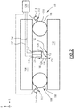
En référence à la
Le véhicule ferroviaire 1 est par exemple un train à grande vitesse, un train suburbain, un métro ou un tramway.The rail vehicle 1 is for example a high speed train, a suburban train, a metro or a tram.
Dans l'exemple de la
En variante non représentée, le véhicule ferroviaire 1 comprend plusieurs bogies et/ou plusieurs caisses.In a variant not shown, the rail vehicle 1 comprises several bogies and / or several boxes.
En variante non représentée encore, le véhicule ferroviaire 1 comprend une seule suspension secondaire ou au moins trois suspensions secondaires.In a variant not yet shown, the rail vehicle 1 comprises a single secondary suspension or at least three secondary suspensions.
Le bogie 2 est configuré pour maintenir les essieux et des roues par l'intermédiaire de suspensions primaires, non représentées. Le bogie 2 est configuré pour supporter la caisse 4 par l'intermédiaire des suspensions secondaires 6.The
La caisse 4 et le bogie 2 définissent ensemble un espacement 8 variable selon une direction d'élévation E du véhicule ferroviaire 1.The
La direction d'élévation E est verticale lorsque le véhicule ferroviaire 1 circule sur des rails horizontaux.The direction of elevation E is vertical when the rail vehicle 1 is traveling on horizontal rails.
On définit également une direction longitudinale L sensiblement perpendiculaire à la direction d'élévation E et correspondant à la direction de circulation du véhicule ferroviaire 1.A longitudinal direction L is also defined which is substantially perpendicular to the direction of elevation E and corresponds to the direction of movement of the rail vehicle 1.
On définit encore une direction transversale T sensiblement perpendiculaire à la direction d'élévation E et à la direction longitudinale L.We also define a transverse direction T substantially perpendicular to the direction of elevation E and to the longitudinal direction L.
Chaque suspension secondaire 6 comprend par exemple un coussin d'air 10 maintenant l'espacement entre le bogie 2 et la caisse 4.Each
Chaque coussin d'air 10 présente par exemple une ouverture 12, munie d'un dispositif de commande d'air 14, tel qu'une électrovanne. Le dispositif de commande d'air 14 est configuré pour fournir de l'air dans le coussin d'air 10 ou laisser échapper de l'air du coussin d'air 10.Each
Par exemple, lorsque le coussin d'air 10 est gonflé, l'espacement 8 est augmenté. La distance entre la caisse 4 et le bogie 2 selon la direction d'élévation E est ainsi augmentée. Lorsqu'une partie de l'air compris dans le coussin d'air 10 est évacué du coussin d'air, via l'ouverture 12, l'espacement 8 est réduit.For example, when the
Le véhicule ferroviaire 1 comprend un premier capteur de proximité 16 et un deuxième capteur de proximité 18.The rail vehicle 1 comprises a
Par exemple, chaque capteur de proximité 16, 18 est un capteur d'induction.For example, each
Par « capteur de proximité », et en particulier par « capteur d'induction », il est entendu un dispositif configuré pour générer un champ magnétique et pour détecter la présence d'une pièce métallique dans le champ magnétique, en particulier par induction. Par exemple, chaque capteur de proximité 16, 18 est configuré pour détecter une surface de la pièce métallique, telle qu'une partie du bogie 2 ou de la caisse 4.By “proximity sensor”, and in particular by “induction sensor”, is meant a device configured to generate a magnetic field and to detect the presence of a metal part in the magnetic field, in particular by induction. For example, each
Dans l'exemple de la
Le premier capteur de proximité 16 est configuré pour détecter, par exemple par induction, la présence d'une première surface 20 lorsque l'espacement 8 est inférieur ou égal à un premier seuil. Le deuxième capteur de proximité 18 est configuré pour détecter, par exemple par induction, la présence d'une deuxième surface 22 lorsque l'espacement 8 est inférieur ou égal à un deuxième seuil distinct du premier seuil.The
Le premier seuil est par exemple un seuil maximal prédéterminé de l'espacement 8 et le deuxième seuil est par exemple un seuil minimal prédéterminé de l'espacement 8. Par exemple, le seuil maximal prédéterminé est compris entre 45 mm et 55 mm et le seuil minimal prédéterminé est compris entre 25 mm et 35 mm.The first threshold is for example a predetermined maximum threshold of the
Selon un autre exemple, le premier seuil est un seul minimal prédéterminé et le deuxième seuil est un seuil maximal prédéterminé de l'espacement 8.According to another example, the first threshold is a single predetermined minimum and the second threshold is a predetermined maximum threshold of the
Par exemple, la première surface 20 et la deuxième surface 22 sont des surfaces du bogie 2. Dans l'exemple représenté sur la
En variante non représentée, la première surface 20 diffère de la deuxième surface 22. Par exemple, la première surface 20 est une surface du bogie 2 et la deuxième surface 22 est une surface de la caisse 4 ou vice-versa.In a variant not shown, the
En variante non représentée, au moins un des premier et deuxième capteurs 16, 18 est fixé au bogie 2. Dans ce cas, la première et/ou la deuxième surface 20, 22 sont notamment des surfaces de la caisse 4.In a variant not shown, at least one of the first and
Dans l'exemple de la
En variante, au moins l'un parmi le premier capteur de proximité 16 et le deuxième capteur de proximité 18 est fixé à l'intérieur du coussin d'air 10. Ce capteur de proximité 16, 18 est par exemple relié à l'un de la caisse 4 et du bogie 2 par l'intermédiaire du coussin d'air 10. Le capteur de proximité 16, 18, selon l'exemple, est configuré pour détecter la présence d'une surface de l'autre du bogie 2 et de la caisse 4, via une partie du coussin d'air 10 couvrant cette surface.As a variant, at least one of the
Le premier et le deuxième capteur de proximité 16, 18 forment un ensemble de capteurs. Selon un exemple, le véhicule ferroviaire 1 comprend un ensemble de capteurs par suspension secondaire 6. Selon un autre exemple, le véhicule ferroviaire 1 comprend un ensemble de capteurs par bogie 2. Selon un autre exemple, le véhicule ferroviaire 1 comprend plusieurs ensembles de capteurs par suspension secondaire 6 et/ou par bogie 2.The first and the
Dans l'exemple de la
Par « sensiblement perpendiculaire », il est entendu une relation de perpendicularité à plus ou moins 10 degrés, de préférence à plus ou moins 5 degrés.By “substantially perpendicular” is meant a relation of perpendicularity to plus or minus 10 degrees, preferably plus or minus 5 degrees.
Le premier capteur de proximité 16 est agencé à une première distance 24 par rapport à la première surface 20, et le deuxième capteur de proximité 18 est agencé à une deuxième distance 26 par rapport à la deuxième surface 22. La première et la deuxième distance 24, 26 sont par exemple définies selon la direction d'élévation E.The
Chaque capteur de proximité 16, 18 présente par exemple une surface émettrice 27.Each
La première distance 24 est par exemple la distance entre la surface émettrice 27 du premier capteur de proximité 16 et la première surface 20. La deuxième distance 26 est par exemple la distance entre la surface émettrice 27 du deuxième capteur de proximité 18 et la deuxième surface 22.The
Selon le premier mode de réalisation, la deuxième distance 26 est distincte de la première distance 24.According to the first embodiment, the
Le premier capteur de proximité 16 est par exemple configuré pour générer un champ magnétique C1 présentant une première fréquence. Le deuxième capteur de proximité 18 est par exemple configuré pour générer un champ magnétique C2 présentant une deuxième fréquence, par exemple distincte de la première fréquence. Le fait que la deuxième fréquence soit distincte de la première fréquence permet d'éviter des interférences entre le champ magnétique C1 généré par le premier capteur de proximité 16 et le champ magnétique C2 généré par le deuxième capteur de proximité 18.The
En variante, la première fréquence est égale à la deuxième fréquence. Par exemple, le premier capteur de proximité 16 est configuré pour générer le champ magnétique C1 à des instants différents de la génération du champ magnétique C2 par le deuxième capteur de proximité 18. Cela permet également d'éviter des interférences.Alternatively, the first frequency is equal to the second frequency. For example, the
Chaque capteur de proximité 16, 18 présente par exemple une portée de détection. Par « portée de détection », il est entendu la plage de distances dans laquelle le capteur de proximité 16, 18 est capable de détecter la première ou deuxième surface 20, 22.Each
Dans la direction d'élévation E, la portée de détection est par exemple comprise entre 0 cm et 50 cm, de préférence entre 0 cm et 5 cm.In the direction of elevation E, the detection range is for example between 0 cm and 50 cm, preferably between 0 cm and 5 cm.
Chaque capteur de proximité 16, 18 présente par exemple une portée maximale de détection. Par « portée maximale de détection », il est entendu la distance maximale à laquelle le capteur de proximité 16, 18 est capable de détecter la première ou deuxième surface 20, 22.Each
Par exemple, chaque capteur de proximité 16, 18 est configuré pour détecter la première ou deuxième surface 20, 22, notamment une surface métallique, par induction lorsque cette surface est présente à une distance 24, 26 par rapport au capteur de proximité 16, 18 qui est inférieure à la portée maximale de détection du capteur. Dans la direction d'élévation E, la portée maximale de détection est par exemple comprise entre 1 cm et 50 cm, de préférence entre 1 cm et 5 cm.For example, each
Par exemple, chaque capteur de proximité 16, 18 n'est pas apte à mesurer la distance entre ce capteur de proximité et la surface 20, 22, mais uniquement à détecter la présence de la surface 20, 22.For example, each
Par exemple, lorsque la surface 20, 22 est agencée à une distance supérieure à la portée maximale de détection, l'induction générée par la surface 20, 22 est inférieure à un seuil d'une induction minimale pour la détection, et la surface 20, 22 n'est ainsi pas détectée par le capteur de proximité 16, 18.For example, when the
Par exemple, le premier capteur de proximité 16 présente une première portée maximale de détection selon la direction d'élévation E. Le premier capteur de proximité 16 est ainsi configuré pour détecter la présence de la première surface 20, lorsque la distance entre cette surface 20 et le premier capteur de proximité 16 est inférieure ou égale à la première portée maximale de détection.For example, the
Le deuxième capteur de proximité 18 présente par exemple une deuxième portée maximale de détection selon la direction d'élévation E. Le deuxième capteur de proximité 18 est ainsi configuré pour détecter la présence de la deuxième surface 22, lorsque la distance entre cette surface 22 et le deuxième capteur de proximité 18 est inférieure ou égale à la deuxième portée maximale de détection.The
Selon le premier mode de réalisation, la première portée maximale de détection est sensiblement égale à la deuxième portée maximale de détection. Par « sensiblement égal(e) », il est entendu une relation d'égalité à plus ou moins 10%, de préférence à plus ou moins 5%.According to the first embodiment, the first maximum detection range is substantially equal to the second maximum detection range. By “substantially equal”, it is understood a relation of equality at plus or minus 10%, preferably at plus or minus 5%.
Le véhicule ferroviaire 1 comprend par exemple en outre un contrôleur 28 configuré pour recevoir, par exemple par une liaison 30, au moins un premier signal de détection du premier capteur de proximité 16 et/ou pour recevoir, par exemple par une liaison 32, un deuxième signal de détection du deuxième capteur de proximité 18. Le premier signal de détection 16 comprend une information relative à la détection de la première surface 20, et le deuxième signal de détection comprend une information relative à la détection de la deuxième surface 22. Chaque liaison 30, 32 est une liaison de données, par exemple une liaison de données sans fil ou une liaison de données avec fil.The rail vehicle 1 further comprises for example a
Le premier et le deuxième signal de détection sont par exemple des signaux binaires. Par exemple, lorsque le premier capteur de proximité 16 détecte la première surface 20, le premier signal de détection est égal à « 1 », sinon le premier signal de détection est égal à « 0 ». Lorsque le deuxième capteur de proximité 18 détecte la deuxième surface 22, le deuxième signal de détection est égal à « 1 », sinon le deuxième signal de détection est égal à « 0 ».The first and the second detection signal are for example binary signals. For example, when the
Le contrôleur 28 est en outre configuré pour envoyer un signal de commande à chaque dispositif de commande d'air 14, en fonction du premier signal de détection et du deuxième signal de détection. Chaque dispositif de commande d'air 14 est ainsi configuré pour introduire de l'air dans les coussins d'air 10 ou pour laisser échapper de l'air des coussins d'air selon le signal de commande reçu.
Par exemple, le contrôleur 28 est configuré pour déterminer que l'espacement est inférieur au premier seuil et au deuxième seuil lorsque le premier et le deuxième signaux de détection sont égaux à « 1 ». Le contrôleur 28 est ainsi configuré pour émettre le signal de commande comprenant une commande d'introduction d'air dans les coussins d'air 10, pour que chaque dispositif de commande d'air 14 introduise de l'air dans le coussin d'air 10 respectif.For example,
Par exemple, le contrôleur 28 est configuré pour déterminer que l'espacement 8 est supérieur au premier seuil et supérieur deuxième seuil lorsque le premier et le deuxième signal de détection sont égaux à « 0 ». Le contrôleur 28 est ainsi configuré pour émettre le signal de commande comprenant une commande d'échappement d'air des coussins d'air 10 pour que chaque dispositif de commande d'air 14 laisse ainsi échapper de l'air du coussin d'air 10 respectif.For example, the
Un procédé de contrôle de l'espacement 8 va maintenant être décrit. Le procédé est mis en œuvre par le véhicule ferroviaire 1.A method of controlling the
Le procédé comprend une première étape de détection, une deuxième étape de détection et une étape de contrôle de l'espacement.The method comprises a first detection step, a second detection step and a spacing control step.
Lors de la première étape de détection, le premier capteur de proximité 16 détecte, par induction, la présence de la première surface 20 lorsque l'espacement 8 est inférieur ou égal au premier seuil, pour obtenir le premier signal de détection.During the first detection step, the
Lorsque le premier capteur de proximité 16 détecte la première surface 20, il envoie par exemple le signal « 1 » au contrôleur 28, et sinon le signal « 0 ».When the
Lors de la deuxième étape de détection, le deuxième capteur de proximité 18 détecte, par induction, la présence de la deuxième surface 22 lorsque l'espacement 8 est inférieur ou égal au deuxième seuil, distinct du premier seuil, pour obtenir le deuxième signal de détection.During the second detection step, the
Lorsque le deuxième capteur de proximité 18 détecte la deuxième surface 22, il envoie par exemple le signal « 1 » au contrôleur, et sinon le signal « 0 ».When the
Lors de l'étape de contrôle, le contrôleur 28 contrôle l'espacement 8 en fonction du premier signal de détection et du deuxième signal de détection.In the controlling step, the
Par exemple, le contrôleur 28 détermine que l'espacement est inférieur au premier seuil et au deuxième seuil lorsque le premier et le deuxième signal de détection sont égaux à « 1 ». Par exemple, le premier capteur de proximité 16 détecte la première surface 20 et le deuxième capteur de proximité 18 détecte la deuxième surface 22. Le contrôleur 28 émet ainsi le signal de commande comprenant une commande d'introduction d'air dans les coussins d'air 10. Chaque dispositif de commande d'air 14 introduit ainsi de l'air dans le coussin d'air 10 respectif.For example, the
Lorsque le premier et le deuxième signal de détection sont égaux à « 0 », le contrôleur 28 détermine que l'espacement 8 est supérieur au premier seuil et supérieur deuxième seuil. Par exemple, aucun des premier et deuxième capteurs de proximité 16, 18 ne détecte la surface 20, 22 respective. Le contrôleur 28 émet ainsi le signal de commande comprenant une commande d'échappement d'air des coussins d'air 10. Chaque dispositif de commande d'air 14 laisse ainsi échapper de l'air du coussin d'air 10 respectif.When the first and second detection signals are equal to "0", the
Lorsque le premier signal de détection est égal à « 1 » et le deuxième signal de détection est égal à « 0 » ou vice-versa, le contrôleur 28 détermine que l'espacement 8 est inférieur ou égal au premier seuil et supérieur au deuxième seuil ou vice-versa. L'espacement 8 présente ainsi une distance entre le bogie et la caisse qui est comprise dans une plage prédéfinie pour l'opération du véhicule ferroviaire, à savoir entre le premier et le deuxième seuil. Dans ce cas, le contrôleur 28 n'émet par exemple pas le signal de commande.When the first detection signal is equal to "1" and the second detection signal is equal to "0" or vice versa, the
Grâce aux caractéristiques décrites ci-dessus, l'espacement entre la caisse 4 et le bogie 2 est contrôlé de façon plus simple, tout en étant fiable. Le premier capteur de proximité 16 et le deuxième capteur de proximité 18 permettent en effet de déterminer l'espacement 8 par détection de la présence de la première surface 20 ou de la deuxième surface 22. Le contrôle est ainsi très simple.Thanks to the characteristics described above, the spacing between the
En outre, le contrôle de l'espacement 8 est fiable, notamment car la détection par induction est indépendante d'impacts environnementaux, tels de salissures ou de neige sur le premier ou le deuxième capteur de proximité 16, 18.In addition, the control of the
Le premier capteur de proximité 16 et le deuxième capteur de proximité 18 permettent ensemble de déterminer si l'espacement 8 est compris entre le premier seuil et le deuxième seuil.The
Le fait que la deuxième distance 26 est distincte de la première distance 24 permet par exemple d'utiliser des capteurs 16, 18 présentant un fonctionnement identique, par exemple présentant une portée maximale de détection du premier capteur de proximité 16 égale à celle du deuxième capteur de proximité 18. Cela facilite ainsi le choix et/ou le paramétrage des capteurs de proximité 16, 18.The fact that the
En référence à la
Le premier capteur de proximité 116 est situé à une première distance 124 par rapport à la première surface 120, et le deuxième capteur de proximité 118 est situé à une deuxième distance 126 par rapport à la deuxième surface 122. La deuxième distance 126 est sensiblement égale à la première distance 124 selon le présent mode de réalisation.The
Par exemple, l'installation du premier et deuxième capteur de proximité 116, 118 est facilité lorsque la première distance 124 est égale à la deuxième distance 126. Par exemple, lorsque les capteurs sont installés à la même hauteur selon la direction d'élévation E, l'installation est rapide et facile, car aucune mesure de distance par exemple de la différence de la première distance 124 par rapport à la deuxième distance 126, par exemple au vu d'une calibration, n'est requise.For example, the installation of the first and
La première portée maximale de détection est différente de la deuxième portée maximale de détection. Par exemple, la différence de la première par rapport à la deuxième portée maximale de détection est sensiblement égale à la différence entre le premier seuil et le deuxième seuil de l'espacement. Par exemple, la différence est comprise entre 10 mm et 30 mm.The first maximum detection range is different from the second maximum detection range. For example, the difference between the first and the second maximum detection range is substantially equal to the difference between the first threshold and the second threshold of the separation. For example, the difference is between 10mm and 30mm.
Par exemple, la différence de la première par rapport à la deuxième portée maximale de détection selon le deuxième mode de réalisation est sensiblement égale à la différence entre la première distance 24 et la deuxième distance 26 de la
Un procédé de contrôle de l'espacement 108 est mis en œuvre par le véhicule ferroviaire 100. Le procédé de contrôle est identique au procédé de contrôle mis en œuvre par le véhicule ferroviaire 1 du premier mode de réalisation. Le procédé n'est ainsi pas décrit à nouveau.A method of checking the
Les avantages du deuxième mode de réalisation sont les mêmes que ceux du premier mode de réalisation.The advantages of the second embodiment are the same as those of the first embodiment.
On conçoit que des caractéristiques du premier et du deuxième mode de réalisation peuvent être combinées.It will be appreciated that features of the first and second embodiments can be combined.
Selon un exemple, la première distance 24 et la deuxième distance sont différentes l'une par rapport à l'autre. Dans cet exemple, la première portée maximale de détection est différente de la deuxième portée maximale de détection.According to one example, the
Claims (9)
caractérisé en ce que le véhicule ferroviaire (1, 100) comprend au moins un premier capteur de proximité (16, 116) relié à l'un de la caisse (4, 104) et du bogie (2, 102), le premier capteur de proximité (16, 116) étant configuré pour détecter, notamment par induction, la présence d'une première surface (20, 120) de l'autre du bogie (2, 102) et de la caisse (4, 104) lorsque l'espacement (8, 108) est inférieur ou égal à un premier seuil, et
en ce que le véhicule ferroviaire (1, 100) comprend au moins un deuxième capteur de proximité (18, 118) relié à l'un de la caisse (4, 104) et du bogie (2, 102), le deuxième capteur de proximité (18, 118) étant configuré pour détecter, notamment par induction, la présence d'une deuxième surface (22, 122) de l'autre du bogie (2, 102) et de la caisse (4, 104) lorsque l'espacement (8, 108) est inférieur ou égal à un deuxième seuil, distinct du premier seuil.Railway vehicle (1, 100) comprising at least one bogie (2, 102), at least one body (4, 104), and at least one secondary suspension (6, 106) connecting the body (4, 104) and the bogie (2, 102), the body (4, 104) and the bogie (2, 102) defining a spacing (8, 108) variable in an elevation direction (E) of the rail vehicle (1, 100),
characterized in that the rail vehicle (1, 100) comprises at least a first proximity sensor (16, 116) connected to one of the body (4, 104) and of the bogie (2, 102), the first sensor proximity (16, 116) being configured to detect, in particular by induction, the presence of a first surface (20, 120) of the other of the bogie (2, 102) and of the body (4, 104) when the 'spacing (8, 108) is less than or equal to a first threshold, and
in that the rail vehicle (1, 100) comprises at least a second proximity sensor (18, 118) connected to one of the body (4, 104) and of the bogie (2, 102), the second sensor of proximity (18, 118) being configured to detect, in particular by induction, the presence of a second surface (22, 122) of the other of the bogie (2, 102) and of the body (4, 104) when the spacing (8, 108) is less than or equal to a second threshold, distinct from the first threshold.
dans lequel le deuxième capteur de proximité (18, 118) présente une deuxième portée maximale de détection selon la direction d'élévation (E), le deuxième capteur de proximité (18, 118) étant configuré pour détecter la présence de la deuxième surface (22, 122) lorsque la distance entre la deuxième surface (22, 122) et le deuxième capteur de proximité (18, 118) est inférieure ou égale à la deuxième portée maximale de détection, et
dans lequel la première portée maximale de détection est différente de la deuxième portée maximale de détection.Rail vehicle (1, 100) according to any one of the preceding claims, in which the first proximity sensor (16, 116) has a first maximum detection range according to the direction of elevation (E) of the rail vehicle (1, 100), the first proximity sensor (16, 116) being configured to detect the presence of the first surface (20, 120) when the distance between the first surface (20, 120) and the first proximity sensor (16, 116) is less than or equal to the first maximum detection range, and
wherein the second proximity sensor (18, 118) has a second maximum detection range in the direction of elevation (E), the second proximity sensor (18, 118) being configured to detect the presence of the second surface ( 22, 122) when the distance between the second surface (22, 122) and the second proximity sensor (18, 118) is less than or equal to the second maximum detection range, and
wherein the first maximum detection range is different from the second maximum detection range.
dans lequel le deuxième capteur de proximité (18, 118) présente une deuxième portée maximale de détection selon la direction d'élévation (E), le deuxième capteur de proximité (18, 118) étant configuré pour détecter la présence de la deuxième surface (22, 122) lorsque la distance entre la deuxième surface (22, 122) et le deuxième capteur de proximité (18, 118) est inférieure ou égale à la deuxième portée maximale de détection, et
dans lequel la première portée maximale de détection est sensiblement égale à la deuxième portée maximale de détection.Rail vehicle (1, 100) according to claim 1 or 2, wherein the first proximity sensor (16, 116) has a first maximum detection range according to the direction of elevation (E) of the rail vehicle (1, 100) , the first proximity sensor (16, 116) being configured to detect the presence of the first surface (20, 120) when the distance between the first surface (20, 120) and the first proximity sensor (16, 116) is less than or equal to the first maximum detection range,
wherein the second proximity sensor (18, 118) has a second maximum detection range in the direction of elevation (E), the second proximity sensor (18, 118) being configured to detect the presence of the second surface ( 22, 122) when the distance between the second surface (22, 122) and the second proximity sensor (18, 118) is less than or equal to the second maximum detection range, and
wherein the first maximum detection range is substantially equal to the second maximum detection range.
Applications Claiming Priority (1)
| Application Number | Priority Date | Filing Date | Title |
|---|---|---|---|
| FR2002792A FR3108300B1 (en) | 2020-03-23 | 2020-03-23 | Railway vehicle and associated method |
Publications (2)
| Publication Number | Publication Date |
|---|---|
| EP3885231A1 true EP3885231A1 (en) | 2021-09-29 |
| EP3885231B1 EP3885231B1 (en) | 2023-01-25 |
Family
ID=70918630
Family Applications (1)
| Application Number | Title | Priority Date | Filing Date |
|---|---|---|---|
| EP21163907.5A Active EP3885231B1 (en) | 2020-03-23 | 2021-03-22 | Railway vehicle and associated method |
Country Status (4)
| Country | Link |
|---|---|
| EP (1) | EP3885231B1 (en) |
| ES (1) | ES2942218T3 (en) |
| FR (1) | FR3108300B1 (en) |
| PT (1) | PT3885231T (en) |
Citations (6)
| Publication number | Priority date | Publication date | Assignee | Title |
|---|---|---|---|---|
| JP2004182000A (en) * | 2002-11-29 | 2004-07-02 | Sumitomo Metal Ind Ltd | Fail safe method of car body inclination control, device, railroad vehicle and curve determining method used for this method |
| JP2006231968A (en) * | 2005-02-22 | 2006-09-07 | Nippon Sharyo Seizo Kaisha Ltd | Railway vehicle |
| JP2007131125A (en) * | 2005-11-10 | 2007-05-31 | Central Japan Railway Co | Method of detecting abnormal condition of vehicle body inclination device |
| EP2692608A1 (en) * | 2011-03-31 | 2014-02-05 | Nippon Steel & Sumitomo Metal Corporation | Method for controlling body lean of railroad car |
| EP3053803A1 (en) * | 2013-10-04 | 2016-08-10 | Nippon Steel & Sumitomo Metal Corporation | Abnormality detection method for car body inclination control device |
| DE102016222663A1 (en) * | 2016-11-17 | 2018-05-17 | Contitech Luftfedersysteme Gmbh | Rail vehicle suspension and spring system for a rail vehicle |
-
2020
- 2020-03-23 FR FR2002792A patent/FR3108300B1/en active Active
-
2021
- 2021-03-22 ES ES21163907T patent/ES2942218T3/en active Active
- 2021-03-22 EP EP21163907.5A patent/EP3885231B1/en active Active
- 2021-03-22 PT PT211639075T patent/PT3885231T/en unknown
Patent Citations (6)
| Publication number | Priority date | Publication date | Assignee | Title |
|---|---|---|---|---|
| JP2004182000A (en) * | 2002-11-29 | 2004-07-02 | Sumitomo Metal Ind Ltd | Fail safe method of car body inclination control, device, railroad vehicle and curve determining method used for this method |
| JP2006231968A (en) * | 2005-02-22 | 2006-09-07 | Nippon Sharyo Seizo Kaisha Ltd | Railway vehicle |
| JP2007131125A (en) * | 2005-11-10 | 2007-05-31 | Central Japan Railway Co | Method of detecting abnormal condition of vehicle body inclination device |
| EP2692608A1 (en) * | 2011-03-31 | 2014-02-05 | Nippon Steel & Sumitomo Metal Corporation | Method for controlling body lean of railroad car |
| EP3053803A1 (en) * | 2013-10-04 | 2016-08-10 | Nippon Steel & Sumitomo Metal Corporation | Abnormality detection method for car body inclination control device |
| DE102016222663A1 (en) * | 2016-11-17 | 2018-05-17 | Contitech Luftfedersysteme Gmbh | Rail vehicle suspension and spring system for a rail vehicle |
Also Published As
| Publication number | Publication date |
|---|---|
| FR3108300B1 (en) | 2022-04-01 |
| EP3885231B1 (en) | 2023-01-25 |
| FR3108300A1 (en) | 2021-09-24 |
| ES2942218T3 (en) | 2023-05-30 |
| PT3885231T (en) | 2023-04-14 |
Similar Documents
| Publication | Publication Date | Title |
|---|---|---|
| EP3792213A1 (en) | Oscillating axle for a lifting machine, lifting machine comprising such an axle and control method | |
| FR2683627A1 (en) | MEASURING DEVICE FOR THE CONTINUOUS MEASUREMENT OF ONDULATORY DIFFERENCES OF A RAIL. | |
| EP0160591A1 (en) | Method and apparatus for the non-destructive testing of railway rails | |
| EP0374395A2 (en) | Method and apparatus for precisely positioning a part displaced along a rail transversely to this rail | |
| TWI798186B (en) | Rail inspection device and rail inspection system | |
| JP4915800B2 (en) | Conveyor rail wear inspection device | |
| EP2406116B1 (en) | Method and device for monitoring the presence of a rail | |
| EP3608195A1 (en) | Method for controlling the height of a vehicle and associated vehicle | |
| EP3885231B1 (en) | Railway vehicle and associated method | |
| EP3241785A1 (en) | Belt conveyor with a device for assessing the belt tension | |
| JPH10339629A (en) | Measuring device | |
| FR3091919B1 (en) | Non-contact measuring device for the thickness of a contact wire of a catenary | |
| CA2443588C (en) | Process and device for the locating of a ledge placed at the junction of two globally plane surfaces | |
| EP3273214B1 (en) | Method for measuring the inflation pressure of tyres fitted on a vehicle travelling on a roadway | |
| FR3085621A1 (en) | RAIL VEHICLE COMPRISING AN ADJUSTING MEMBER OF A SECONDARY SUSPENSION SYSTEM | |
| EP0439401A1 (en) | Pantograph with dampened head suspension | |
| EP3620344B1 (en) | Railway vehicle comprising an element for adjusting a secondary suspension system | |
| EP2691780B1 (en) | Method and system for measuring variations in the speed of a mobile body | |
| EP3403897B1 (en) | Device for attaching a cylinder for actuating a magnetic shoe of a railway vehicle bogie, associated bogie and railway vehicle | |
| FR3010517A1 (en) | TRUCK | |
| CH437411A (en) | Method for controlling the rails of a railway track and device for implementing this method | |
| JP5931535B2 (en) | Inspection vehicle shake state correction method and apparatus, and inspection method and apparatus | |
| FR3017137A1 (en) | DEVICE FOR MEASURING THE STATE OF A CIRCULATION PATH OF A GUIDE VEHICLE | |
| JPH0349365B2 (en) | ||
| FR3041432A1 (en) | METHOD AND DEVICE FOR DETECTING A FAULT IN A WHEEL OF A MOTOR VEHICLE |
Legal Events
| Date | Code | Title | Description |
|---|---|---|---|
| PUAI | Public reference made under article 153(3) epc to a published international application that has entered the european phase |
Free format text: ORIGINAL CODE: 0009012 |
|
| STAA | Information on the status of an ep patent application or granted ep patent |
Free format text: STATUS: THE APPLICATION HAS BEEN PUBLISHED |
|
| STAA | Information on the status of an ep patent application or granted ep patent |
Free format text: STATUS: REQUEST FOR EXAMINATION WAS MADE |
|
| AK | Designated contracting states |
Kind code of ref document: A1 Designated state(s): AL AT BE BG CH CY CZ DE DK EE ES FI FR GB GR HR HU IE IS IT LI LT LU LV MC MK MT NL NO PL PT RO RS SE SI SK SM TR |
|
| 17P | Request for examination filed |
Effective date: 20210913 |
|
| RBV | Designated contracting states (corrected) |
Designated state(s): AL AT BE BG CH CY CZ DE DK EE ES FI FR GB GR HR HU IE IS IT LI LT LU LV MC MK MT NL NO PL PT RO RS SE SI SK SM TR |
|
| GRAP | Despatch of communication of intention to grant a patent |
Free format text: ORIGINAL CODE: EPIDOSNIGR1 |
|
| STAA | Information on the status of an ep patent application or granted ep patent |
Free format text: STATUS: GRANT OF PATENT IS INTENDED |
|
| INTG | Intention to grant announced |
Effective date: 20220824 |
|
| GRAS | Grant fee paid |
Free format text: ORIGINAL CODE: EPIDOSNIGR3 |
|
| GRAA | (expected) grant |
Free format text: ORIGINAL CODE: 0009210 |
|
| STAA | Information on the status of an ep patent application or granted ep patent |
Free format text: STATUS: THE PATENT HAS BEEN GRANTED |
|
| AK | Designated contracting states |
Kind code of ref document: B1 Designated state(s): AL AT BE BG CH CY CZ DE DK EE ES FI FR GB GR HR HU IE IS IT LI LT LU LV MC MK MT NL NO PL PT RO RS SE SI SK SM TR |
|
| REG | Reference to a national code |
Ref country code: GB Ref legal event code: FG4D Free format text: NOT ENGLISH |
|
| RIN1 | Information on inventor provided before grant (corrected) |
Inventor name: NICOLEAU, GREGOIRE Inventor name: ESSOH, FABRICE |
|
| REG | Reference to a national code |
Ref country code: CH Ref legal event code: EP |
|
| REG | Reference to a national code |
Ref country code: AT Ref legal event code: REF Ref document number: 1545724 Country of ref document: AT Kind code of ref document: T Effective date: 20230215 Ref country code: IE Ref legal event code: FG4D Free format text: LANGUAGE OF EP DOCUMENT: FRENCH |
|
| REG | Reference to a national code |
Ref country code: DE Ref legal event code: R096 Ref document number: 602021001295 Country of ref document: DE |
|
| REG | Reference to a national code |
Ref country code: PT Ref legal event code: SC4A Ref document number: 3885231 Country of ref document: PT Date of ref document: 20230414 Kind code of ref document: T Free format text: AVAILABILITY OF NATIONAL TRANSLATION Effective date: 20230410 |
|
| PGFP | Annual fee paid to national office [announced via postgrant information from national office to epo] |
Ref country code: FR Payment date: 20230321 Year of fee payment: 3 |
|
| REG | Reference to a national code |
Ref country code: LT Ref legal event code: MG9D |
|
| REG | Reference to a national code |
Ref country code: ES Ref legal event code: FG2A Ref document number: 2942218 Country of ref document: ES Kind code of ref document: T3 Effective date: 20230530 |
|
| PGFP | Annual fee paid to national office [announced via postgrant information from national office to epo] |
Ref country code: BE Payment date: 20230321 Year of fee payment: 3 |
|
| REG | Reference to a national code |
Ref country code: NL Ref legal event code: MP Effective date: 20230125 |
|
| REG | Reference to a national code |
Ref country code: AT Ref legal event code: MK05 Ref document number: 1545724 Country of ref document: AT Kind code of ref document: T Effective date: 20230125 |
|
| PG25 | Lapsed in a contracting state [announced via postgrant information from national office to epo] |
Ref country code: NL Free format text: LAPSE BECAUSE OF FAILURE TO SUBMIT A TRANSLATION OF THE DESCRIPTION OR TO PAY THE FEE WITHIN THE PRESCRIBED TIME-LIMIT Effective date: 20230125 |
|
| PG25 | Lapsed in a contracting state [announced via postgrant information from national office to epo] |
Ref country code: RS Free format text: LAPSE BECAUSE OF FAILURE TO SUBMIT A TRANSLATION OF THE DESCRIPTION OR TO PAY THE FEE WITHIN THE PRESCRIBED TIME-LIMIT Effective date: 20230125 Ref country code: NO Free format text: LAPSE BECAUSE OF FAILURE TO SUBMIT A TRANSLATION OF THE DESCRIPTION OR TO PAY THE FEE WITHIN THE PRESCRIBED TIME-LIMIT Effective date: 20230425 Ref country code: LV Free format text: LAPSE BECAUSE OF FAILURE TO SUBMIT A TRANSLATION OF THE DESCRIPTION OR TO PAY THE FEE WITHIN THE PRESCRIBED TIME-LIMIT Effective date: 20230125 Ref country code: LT Free format text: LAPSE BECAUSE OF FAILURE TO SUBMIT A TRANSLATION OF THE DESCRIPTION OR TO PAY THE FEE WITHIN THE PRESCRIBED TIME-LIMIT Effective date: 20230125 Ref country code: HR Free format text: LAPSE BECAUSE OF FAILURE TO SUBMIT A TRANSLATION OF THE DESCRIPTION OR TO PAY THE FEE WITHIN THE PRESCRIBED TIME-LIMIT Effective date: 20230125 Ref country code: AT Free format text: LAPSE BECAUSE OF FAILURE TO SUBMIT A TRANSLATION OF THE DESCRIPTION OR TO PAY THE FEE WITHIN THE PRESCRIBED TIME-LIMIT Effective date: 20230125 |
|
| PGFP | Annual fee paid to national office [announced via postgrant information from national office to epo] |
Ref country code: IT Payment date: 20230331 Year of fee payment: 3 Ref country code: ES Payment date: 20230529 Year of fee payment: 3 |
|
| PG25 | Lapsed in a contracting state [announced via postgrant information from national office to epo] |
Ref country code: SE Free format text: LAPSE BECAUSE OF FAILURE TO SUBMIT A TRANSLATION OF THE DESCRIPTION OR TO PAY THE FEE WITHIN THE PRESCRIBED TIME-LIMIT Effective date: 20230125 Ref country code: PL Free format text: LAPSE BECAUSE OF FAILURE TO SUBMIT A TRANSLATION OF THE DESCRIPTION OR TO PAY THE FEE WITHIN THE PRESCRIBED TIME-LIMIT Effective date: 20230125 Ref country code: IS Free format text: LAPSE BECAUSE OF FAILURE TO SUBMIT A TRANSLATION OF THE DESCRIPTION OR TO PAY THE FEE WITHIN THE PRESCRIBED TIME-LIMIT Effective date: 20230525 Ref country code: GR Free format text: LAPSE BECAUSE OF FAILURE TO SUBMIT A TRANSLATION OF THE DESCRIPTION OR TO PAY THE FEE WITHIN THE PRESCRIBED TIME-LIMIT Effective date: 20230426 Ref country code: FI Free format text: LAPSE BECAUSE OF FAILURE TO SUBMIT A TRANSLATION OF THE DESCRIPTION OR TO PAY THE FEE WITHIN THE PRESCRIBED TIME-LIMIT Effective date: 20230125 |
|
| P01 | Opt-out of the competence of the unified patent court (upc) registered |
Effective date: 20230823 |
|
| RAP2 | Party data changed (patent owner data changed or rights of a patent transferred) |
Owner name: ALSTOM HOLDINGS |
|
| REG | Reference to a national code |
Ref country code: DE Ref legal event code: R097 Ref document number: 602021001295 Country of ref document: DE |
|
| PG25 | Lapsed in a contracting state [announced via postgrant information from national office to epo] |
Ref country code: SM Free format text: LAPSE BECAUSE OF FAILURE TO SUBMIT A TRANSLATION OF THE DESCRIPTION OR TO PAY THE FEE WITHIN THE PRESCRIBED TIME-LIMIT Effective date: 20230125 Ref country code: RO Free format text: LAPSE BECAUSE OF FAILURE TO SUBMIT A TRANSLATION OF THE DESCRIPTION OR TO PAY THE FEE WITHIN THE PRESCRIBED TIME-LIMIT Effective date: 20230125 Ref country code: MC Free format text: LAPSE BECAUSE OF FAILURE TO SUBMIT A TRANSLATION OF THE DESCRIPTION OR TO PAY THE FEE WITHIN THE PRESCRIBED TIME-LIMIT Effective date: 20230125 Ref country code: EE Free format text: LAPSE BECAUSE OF FAILURE TO SUBMIT A TRANSLATION OF THE DESCRIPTION OR TO PAY THE FEE WITHIN THE PRESCRIBED TIME-LIMIT Effective date: 20230125 Ref country code: DK Free format text: LAPSE BECAUSE OF FAILURE TO SUBMIT A TRANSLATION OF THE DESCRIPTION OR TO PAY THE FEE WITHIN THE PRESCRIBED TIME-LIMIT Effective date: 20230125 Ref country code: CZ Free format text: LAPSE BECAUSE OF FAILURE TO SUBMIT A TRANSLATION OF THE DESCRIPTION OR TO PAY THE FEE WITHIN THE PRESCRIBED TIME-LIMIT Effective date: 20230125 |
|
| PG25 | Lapsed in a contracting state [announced via postgrant information from national office to epo] |
Ref country code: SK Free format text: LAPSE BECAUSE OF FAILURE TO SUBMIT A TRANSLATION OF THE DESCRIPTION OR TO PAY THE FEE WITHIN THE PRESCRIBED TIME-LIMIT Effective date: 20230125 |
|
| PLBE | No opposition filed within time limit |
Free format text: ORIGINAL CODE: 0009261 |
|
| STAA | Information on the status of an ep patent application or granted ep patent |
Free format text: STATUS: NO OPPOSITION FILED WITHIN TIME LIMIT |
|
| PG25 | Lapsed in a contracting state [announced via postgrant information from national office to epo] |
Ref country code: LU Free format text: LAPSE BECAUSE OF NON-PAYMENT OF DUE FEES Effective date: 20230322 |
|
| 26N | No opposition filed |
Effective date: 20231026 |
|
| REG | Reference to a national code |
Ref country code: IE Ref legal event code: MM4A |
|
| PG25 | Lapsed in a contracting state [announced via postgrant information from national office to epo] |
Ref country code: SI Free format text: LAPSE BECAUSE OF FAILURE TO SUBMIT A TRANSLATION OF THE DESCRIPTION OR TO PAY THE FEE WITHIN THE PRESCRIBED TIME-LIMIT Effective date: 20230125 Ref country code: IE Free format text: LAPSE BECAUSE OF NON-PAYMENT OF DUE FEES Effective date: 20230322 |
|
| PGFP | Annual fee paid to national office [announced via postgrant information from national office to epo] |
Ref country code: PT Payment date: 20231222 Year of fee payment: 4 |
|
| PGFP | Annual fee paid to national office [announced via postgrant information from national office to epo] |
Ref country code: DE Payment date: 20240320 Year of fee payment: 4 |