EP3885201B1 - Véhicule doté d'un capteur de recul sécurisé - Google Patents
Véhicule doté d'un capteur de recul sécurisé Download PDFInfo
- Publication number
- EP3885201B1 EP3885201B1 EP21159037.7A EP21159037A EP3885201B1 EP 3885201 B1 EP3885201 B1 EP 3885201B1 EP 21159037 A EP21159037 A EP 21159037A EP 3885201 B1 EP3885201 B1 EP 3885201B1
- Authority
- EP
- European Patent Office
- Prior art keywords
- opening
- sensor
- guide element
- vehicle
- crossmember
- Prior art date
- Legal status (The legal status is an assumption and is not a legal conclusion. Google has not performed a legal analysis and makes no representation as to the accuracy of the status listed.)
- Active
Links
Images


Classifications
-
- B—PERFORMING OPERATIONS; TRANSPORTING
- B60—VEHICLES IN GENERAL
- B60R—VEHICLES, VEHICLE FITTINGS, OR VEHICLE PARTS, NOT OTHERWISE PROVIDED FOR
- B60R19/00—Wheel guards; Radiator guards, e.g. grilles; Obstruction removers; Fittings damping bouncing force in collisions
- B60R19/02—Bumpers, i.e. impact receiving or absorbing members for protecting vehicles or fending off blows from other vehicles or objects
- B60R19/48—Bumpers, i.e. impact receiving or absorbing members for protecting vehicles or fending off blows from other vehicles or objects combined with, or convertible into, other devices or objects, e.g. bumpers combined with road brushes, bumpers convertible into beds
- B60R19/483—Bumpers, i.e. impact receiving or absorbing members for protecting vehicles or fending off blows from other vehicles or objects combined with, or convertible into, other devices or objects, e.g. bumpers combined with road brushes, bumpers convertible into beds with obstacle sensors of electric or electronic type
-
- B—PERFORMING OPERATIONS; TRANSPORTING
- B60—VEHICLES IN GENERAL
- B60R—VEHICLES, VEHICLE FITTINGS, OR VEHICLE PARTS, NOT OTHERWISE PROVIDED FOR
- B60R21/00—Arrangements or fittings on vehicles for protecting or preventing injuries to occupants or pedestrians in case of accidents or other traffic risks
- B60R21/01—Electrical circuits for triggering passive safety arrangements, e.g. airbags, safety belt tighteners, in case of vehicle accidents or impending vehicle accidents
- B60R21/013—Electrical circuits for triggering passive safety arrangements, e.g. airbags, safety belt tighteners, in case of vehicle accidents or impending vehicle accidents including means for detecting collisions, impending collisions or roll-over
- B60R21/0136—Electrical circuits for triggering passive safety arrangements, e.g. airbags, safety belt tighteners, in case of vehicle accidents or impending vehicle accidents including means for detecting collisions, impending collisions or roll-over responsive to actual contact with an obstacle, e.g. to vehicle deformation, bumper displacement or bumper velocity relative to the vehicle
-
- B—PERFORMING OPERATIONS; TRANSPORTING
- B60—VEHICLES IN GENERAL
- B60R—VEHICLES, VEHICLE FITTINGS, OR VEHICLE PARTS, NOT OTHERWISE PROVIDED FOR
- B60R19/00—Wheel guards; Radiator guards, e.g. grilles; Obstruction removers; Fittings damping bouncing force in collisions
- B60R19/02—Bumpers, i.e. impact receiving or absorbing members for protecting vehicles or fending off blows from other vehicles or objects
- B60R19/18—Bumpers, i.e. impact receiving or absorbing members for protecting vehicles or fending off blows from other vehicles or objects characterised by the cross-section; Means within the bumper to absorb impact
- B60R2019/1806—Structural beams therefor, e.g. shock-absorbing
Definitions
- the present invention relates to a vehicle provided with a secure reversing sensor.
- X is a front-rear longitudinal axis of the vehicle oriented towards the vehicle.
- Y is a transverse axis directed towards the right of the vehicle and Z is a vertical axis directed upwards.
- US 7,607,705 discloses a vehicle according to the preamble of claim 1.
- Some vehicles have a reversing sensor placed in a rear bumper and intended to inform the driver of the distance that remains to be covered before impacting an object located at the rear of the vehicle. This information is transmitted by means of a beep emitted in the passenger compartment of the vehicle, the frequency of which increases as the vehicle approaches the object, becoming continuous when the vehicle is about to to touch that object.
- this sensor is placed behind a rigid rear cross member of the vehicle, which has been sized to absorb the energy produced during a rear impact of the vehicle against an external object.
- the consequences of such positioning are that, during an accidental impact at very low speed, typically less than 4 km/h, produced against the rear bumper, for example by a driver wishing to park his vehicle by carrying out small maneuvers, the reversing sensor will impact the rear cross member. It may then be damaged and it will have to be changed.
- a first solution to solve this problem was to create an opening in the rear crossmember, placed in front of the sensor, so that the latter could enter said opening while avoiding impacting the rear crossmember, during small shocks produced against the bumper. - rear shocks.
- this opening is not extensible and must have a maximum size, otherwise the damping function of the rear cross member will be impaired.
- the small shocks produced on the rear bumper are not made in a horizontal direction along which the sensor and the opening are aligned, the sensor risks impacting an edge of the crosspiece delimiting said opening. It will then be damaged and will need to be replaced.
- a vehicle according to the invention has a rear cross member designed so that the sensor never comes to impact it during small shocks produced on the rear bumper, including when these shocks are not strictly produced along an axis joining the center of the sensor to the center of the aperture.
- the subject of the invention is a vehicle comprising a rear shock-absorbing crossmember, a rear bumper and a reversing sensor, said sensor being supported by the bumper.
- the crosspiece has an opening located in front of the sensor, and a guide element is fixed to the crosspiece, so as to guide the movement of the sensor towards the opening in the event of an accidental shock at reduced speed caused on the rear bumper by an external object.
- the reversing sensor is moved towards the front of the vehicle in the direction of the rear crossmember, said sensor then coming into contact with a wall of the vehicle. guide element to slide along it, in order to be conveyed to the opening of the rear crosspiece.
- the guide element is configured to prevent a sudden impact of the sensor against the crosspiece by deflecting it towards the opening of said crosspiece. Thanks to the presence of the guide element, the sensor will always be deviated towards the opening of the crosspiece, without the risk of hitting said crosspiece and therefore being damaged.
- the guide element can either form an integral part of the crosspiece and constitute with the latter one and the same piece manufactured in one piece, or constitute an added part which is fixed to the said crosspiece, for example by means of a screwing or clipping.
- the sensor is fixed to a support which is itself secured to the rear bumper, and when small shocks occur on the rear bumper, it is the support which moves towards the rear crossmember.
- the cross member is a part which extends along a transverse axis Y of the vehicle, and which is intended to deform under the effect of a significant impact of an object against the rear bumper in order to protect people who would be seated in a row of rear seats of that vehicle.
- the guide piece comprises at least one wall opening into the opening of the rear crosspiece.
- the opening of the crosspiece has dimensions which are greater than those of the sensor.
- the guide element is configured in such a way that the sensor cannot impact it brutally but can slide along it without a hitch and with a certain smoothness.
- the guide element is a solid part comprising a side wall delimiting a first end opening and a second end opening widened with respect to said first opening, said part being positioned on the crosses so that the first opening is inserted into the opening of said cross and the second opening is placed vis-à-vis the sensor.
- the guide element is a converging hollow part, allowing the reversing sensor, caused to penetrate into the second opening under the effect of small shocks produced on the rear bumper, to slide along the wall side to reach the first opening and thus end up in the opening of the crosspiece.
- the two openings of the guide element are each oblong in shape and are arranged relative to each other while being coaxial.
- the two end openings are inscribed in two parallel planes, and the axis joining the center of said openings is perpendicular to said planes.
- the guide element has a marked character of symmetry and is therefore easy and quick to manufacture.
- it is easy to provide elements for attaching said guide element to said crosspiece.
- the oblong shape of the guide element makes it possible to create an extended space which can advantageously be occupied by equipment, such as for example wiring.
- each of the two openings of the guide element is delimited by two parallel edges connected to each other by two rounded edges.
- This is a particular embodiment of a guide element which is easy to machine.
- the longitudinal axes of the two openings of the guide element are horizontal. This characteristic is true if the vehicle itself rests on level ground.
- the guide element is fixed to the rear crosspiece by clipping.
- This is a simple fixing means, requiring neither specific tools nor complicated manipulations. It can be removed from the crosspiece just as easily, for example by a simple elastic deformation.
- the guide element is made of a hard plastic. In this way, this element is light, while having good mechanical strength. It is also compatible to be elastically deformed in order to be fixed by clipping on the crosspiece or to be removed therefrom.
- the senor is fixed to a support part which is itself secured to the rear bumper.
- this support part to which the sensor is attached which moves towards the rear crossmember.
- the rear crosspiece is made of sheet metal.
- Another object of the invention is a guide element for producing a vehicle according to the invention.
- the invention comprises a side wall delimiting a first end opening and a second end opening widened with respect to said first opening, said two openings each being of oblong shape and being disposed one with respect to being coaxial.
- the two end openings are inscribed in two parallel planes, and the axis joining the center of said openings is perpendicular to said planes.
- a vehicle according to the invention has the advantage of being able to preserve, easily and safely, the reversing sensor when small shocks occur on the rear bumper, thanks to a judicious fixing of a light guide element and simple geometry. It follows that this function safety of the reversing sensor is ensured in the vehicle with mastery, without incurring significant additional costs.
- some vehicle 1 generally comprise a rear cross member 2, a rear bumper and a reversing sensor 3 placed on said rear bumper. More specifically, the sensor 3 is inserted into a support, which is itself secured to the rear bumper. This sensor 3 is activated when the vehicle initiates a reverse gear and approaches an external obstacle, located at the rear of said vehicle 1. This sensor 3 emits beeps, the frequency of which increases when the vehicle approaches the obstacle outside, to turn into a continuous sound when said vehicle 1 is about to touch said obstacle.
- a problem commonly encountered with this type of sensor 3 is that, when for example a second vehicle performs maneuvers behind the present vehicle in an attempt to park, it is likely to impact at least once the rear bumper of said vehicle . It The result is that the reversing sensor 3, which is secured to this rear bumper, risks colliding with the rear crossmember 2 located just in front of it, under the effect of these impacts generally carried out at low speed, typically less than 4 km/h. It is then very likely that sensor 3 will be damaged following this percussion and that it will have to be changed.
- the rear crossmember 2 is preferably made of sheet metal and is configured to be able to deform and thus absorb the energy produced during a significant accidental impact generated at the rear of the vehicle 1, for example by a second vehicle, in order to preserve the physical integrity of people who would be seated inside said vehicle 1.
- This crosspiece 2 is a part which extends along a transverse axis Y of the vehicle, being substantially horizontal.
- a first solution considered to prevent the reversing sensor 3 from colliding with the rear crossmember 2 when small shocks occur against the rear bumper was to make an opening 4 in the crossmember 2, located in front of said sensor 3.
- the center of this opening 4 and the center of the sensor 3 are aligned along a longitudinal axis X and horizontal of the vehicle 1.
- this solution is only valid when the sensor 3 is moved horizontally along the along said axis as illustrated by the arrow 5.
- the small shocks against the rear bumper are no longer made in a direction horizontal but in an oblique direction directed downwards, as illustrated by the arrow 6.
- the sensor 3 tends to move downwards and risks coming into contact with a b ord 7 of the crosspiece 2 delimiting the opening 4. The sensor 3 will therefore be damaged and it will have to be changed.
- a vehicle according to the invention implements a second solution to prevent the reversing sensor 3 from colliding with the rear crossmember 2 when small shocks occur against the rear bumper of said vehicle. This involves attaching to the rear crossmember 2 a guide element 100 so as to always orient the movement of the sensor 3 towards the opening 4 of the rear crossmember 2, regardless of the direction of the small shocks produced on the visor. rear shocks.
- the guide element 100 comprises a diverging side wall 101 delimiting an internal channel having a first end opening 102 and a second end opening 103 widened with respect to said first opening 102.
- the cross section of the internal channel gradually increases from the first end opening 102 towards the second end opening 103.
- the two end openings 102, 103 are each delimited by two rectilinear edges 104, 105, 106 , 107 and by two rounded edges 108, 109, 110, 111 connecting said two rectilinear edges 104, 105, 106, 107, said two openings 102, 103 being coaxial.
- the side wall 101 of the guide element 100 has an external bead 112 located on the side of the first end 102, said bead 112 originating on the edge of the wall 101 delimiting the first end 102, and extending over less half the length of said wall and preferably over less than a quarter of said length.
- One end of this bead 112 located on the side of the second end opening 103 defines with said wall 101 a shoulder 113.
- This guide element 100 is advantageously made of a hard plastic, giving said element 100 good mechanical strength and a certain propensity to elastic deformation.
- the guide element 100 is fixed to the crosspiece 2 by clipping. Indeed, this element 100 is introduced into the opening 4 of the rear crosspiece 2 through the first end opening 102. It is then pushed into said opening 4 by deforming elastically until the shoulder 113 has exceeded the wall of said crosspiece 2 delimiting said opening. The bead 112, which was compressed, relaxes behind said wall, then trapping the guide element 100 in the opening 4 of the crosspiece 2.
- the guide element 100 is clipped to the rear crosspiece 2 so that the rectilinear edges 104, 105, 106, 107 of the two end openings 102, 103 extend parallel to a longitudinal axis of said crosspiece 2.
- first end opening 102 is found in front of the second end opening 103, and the reversing sensor 3 which is secured to the rear bumper is placed opposite and behind said second end opening 103.
- the reversing sensor 3 will move forwards and will systematically enter the second end opening 103 of the guide element.
- the dimensions of said second end opening 103 and the arrangement of the recoil sensor 3 with respect to said second opening 103 mean that the sensor 3 can only penetrate into said second end opening 103, whatever the direction of forward movement of said sensor 3.
- Sensor 3 can then either continue its forward progression inside guide element 100 without touching side wall 101, or come into contact with said wall side 101 and then slide along it while being directed towards the first end opening 102 of said guide element. Due to the slope of the side wall 101 of the guide element 100, the bringing into contact of the recoil sensor 3 with said side wall 101 takes place gently, without generating the slightest shock, thus preserving the integrity of said sensor 3.
- Sensor 3 will then end up in opening 4 of crosspiece 2 without ever having impacted said crosspiece 2.
Landscapes
- Engineering & Computer Science (AREA)
- Mechanical Engineering (AREA)
- Air Bags (AREA)
- Body Structure For Vehicles (AREA)
Description
- La présente invention concerne un véhicule doté d'un capteur de recul sécurisé.
- Afin de bien comprendre le positionnement des différentes pièces impliquées dans un véhicule selon l'invention, la description est réalisée en faisant référence à un repère orthonormé direct XYZ lié au véhicule et dans lequel X est un axe longitudinal avant-arrière du véhicule orienté vers l'arrière, Y est un axe transversal orienté vers la droite du véhicule et Z est un axe vertical dirigé vers le haut.
-
US 7 607 705 divulgue un véhicule selon le préambule de la revendication 1. - Certains véhicules possèdent un capteur de recul placé dans un pare-chocs arrière et destiné à informer le conducteur de la distance qui lui reste à parcourir avant d'impacter un objet situé à l'arrière du véhicule. Cette information est transmise par le biais d'un bip sonore émis dans l'habitacle du véhicule, et dont la fréquence augmente au fur et à mesure que le véhicule se rapproche de l'objet, pour devenir continu lorsque le véhicule est sur le point de toucher ledit objet.
- Actuellement ce capteur se retrouve placé derrière une traverse arrière rigide du véhicule, qui a été dimensionnée pour absorber l'énergie produite lors d'un choc arrière du véhicule contre un objet extérieur. Les conséquences d'un tel positionnement sont que, lors d'un choc accidentel à très faible vitesse typiquement inférieure à 4km/h produit contre le pare-chocs arrière, par exemple par un conducteur désirant garer son véhicule en effectuant de petites manoeuvres, le capteur de recul va venir impacter la traverse arrière. Il risque alors d'être endommagé et il faudra alors le changer.
- Une première solution pour résoudre ce problème a été de créer une ouverture dans la traverse arrière, placée devant le capteur, afin que celui-ci puisse pénétrer dans ladite ouverture en évitant d'impacter la traverse arrière, lors de petits chocs produits contre le pare-chocs arrière. Or, cette ouverture n'est pas extensible et doit posséder une taille maximale, sous peine de dégrader la fonction d'amortissement de la traverse arrière. Il en résulte que si les petits chocs produits sur le pare-chocs arrière ne sont pas réalisés suivant une direction horizontale le long de laquelle sont alignés le capteur et l'ouverture, le capteur risque de venir impacter un bord de la traverse délimitant ladite ouverture. Il sera alors endommagé et il faudra le remplacer.
- Un véhicule selon l'invention possède une traverse arrière conçue pour que le capteur ne vienne jamais l'impacter lors de petits chocs produits sur le pare-chocs arrière, y compris lorsque ces chocs ne sont pas produits rigoureusement le long d'un axe joignant le centre du capteur au centre de l'ouverture.
- L'invention a pour objet un véhicule comprenant une traverse arrière d'amortissement de choc, un pare-chocs arrière et un capteur de recul, ledit capteur étant supporté par le pare-chocs.
- Selon l'invention, la traverse possède une ouverture située devant le capteur, et un élément de guidage est fixé à la traverse, de manière à guider le déplacement du capteur vers l'ouverture dans le cas d'un choc accidentel à vitesse réduite provoqué sur le pare-chocs arrière par un objet extérieur.
- De cette manière, lorsque de petits chocs se produisent sur le pare-chocs arrière du véhicule, le capteur de recul est déplacé vers l'avant du véhicule en direction de la traverse arrière, ledit capteur venant alors au contact d'une paroi de l'élément de guidage pour coulisser le long de celle-ci, afin d'être acheminé vers l'ouverture de la traverse arrière. L'élément de guidage est configuré pour empêcher un impact brutal du capteur contre la traverse en le déviant vers l'ouverture de ladite traverse. Grâce à la présence de l'élément de guidage, le capteur sera toujours dévié vers l'ouverture de la traverse, sans risque de venir percuter ladite traverse et donc d'être endommagé. L'élément de guidage peut, soit faire partie intégrante de la traverse et constituer avec celle-ci une seule et même pièce fabriquée d'un seul tenant, soit constituer une pièce rapportée qui est fixée à ladite traverse par exemple au moyen d'un vissage ou d'un clippage. Avantageusement, le capteur est fixé à un support qui est lui-même solidarisé au pare-chocs arrière, et lorsque de petits chocs se produisent sur le pare-chocs arrière, c'est le support qui se déplace vers la traverse arrière. La traverse est une pièce qui s'étend suivant un axe transversal Y du véhicule, et qui a pour objet de se déformer sous l'effet d'un impact significatif d'un objet contre le pare-chocs arrière afin de protéger des personnes qui seraient assises sur une rangée de sièges arrière dudit véhicule. Avantageusement, la pièce de guidage comprend au moins une paroi débouchant dans l'ouverture de la traverse arrière. L'ouverture de la traverse a des dimensions qui sont supérieures à celles du capteur. L'élément de guidage est configuré de telle sorte que le capteur ne puisse pas venir l'impacter brutalement mais puisse coulisser le long de celui-ci sans accroc et avec une certaine douceur.
- Selon une caractéristique possible de l'invention, l'élément de guidage est une pièce solide comprenant une paroi latérale délimitant une première ouverture d'extrémité et une deuxième ouverture d'extrémité élargie par rapport à ladite première ouverture, ladite pièce étant positionnée sur la traverse de sorte que la première ouverture soit insérée dans l'ouverture de ladite traverse et la deuxième ouverture soit placée en vis-à-vis du capteur. De cette manière, l'élément de guidage est une pièce creuse convergente, permettant au capteur de recul, amené à pénétrer dans la deuxième ouverture sous l'effet de petits chocs produits sur le pare-chocs arrière, de glisser le long de la paroi latérale pour atteindre la première ouverture et ainsi se retrouver dans l'ouverture de la traverse.
- Selon une caractéristique possible de l'invention, les deux ouvertures de l'élément de guidage sont chacune de forme oblongue et sont disposées l'une par rapport à l'autre en étant coaxiales. Autrement dit, les deux ouvertures d'extrémité s'inscrivent dans deux plans parallèles, et l'axe joignant le centre desdites ouvertures est perpendiculaire auxdits plans. De cette manière, l'élément de guidage présente un caractère de symétrie marqué et est donc facile et rapide à fabriquer. Pour cette configuration, il est aisé de prévoir des éléments d'attache dudit élément de guidage sur ladite traverse. La forme oblongue de l'élément de guidage permet de créer un espace étendu qui peut avantageusement être occupé par des équipements, tels que par exemple des câblages.
- Selon une caractéristique possible de l'invention, chacune des deux ouvertures de l'élément de guidage est délimitée par deux bords parallèles reliés entre eux par deux bords arrondis. Il s'agit d'un mode de réalisation particulier d'un élément de guidage qui est facile à usiner.
- Selon une caractéristique possible de l'invention, les axes longitudinaux des deux ouvertures de l'élément de guidage sont horizontaux. Cette caractéristique est vraie si le véhicule repose lui-même sur un sol horizontal.
- Selon une caractéristique possible de l'invention, l'élément de guidage est fixé à la traverse arrière par clippage. Il s'agit d'un moyen de fixation simple, ne nécessitant, ni un outillage spécifique, ni des manipulations compliquées. Il peut être retiré de la traverse tout aussi facilement, par exemple par une simple déformation élastique.
- Selon une caractéristique possible de l'invention, l'élément de guidage est réalisé dans un plastique dur. De cette manière, cet élément est léger, tout en présentant une bonne tenue mécanique. Il est également compatible pour être déformé élastiquement dans le but d'être fixé par clippage sur la traverse ou être retiré de celle-ci.
- Selon une caractéristique possible de l'invention, le capteur est fixé à une pièce support qui est elle-même solidarisée au pare-chocs arrière. Pour une telle configuration, lorsque de petits chocs se produisent sur le pare-chocs arrière, c'est cette pièce support à laquelle est fixé le capteur qui se déplace vers la traverse arrière.
- Selon une caractéristique possible de l'invention, la traverse arrière est en tôle.
- L'invention a pour autre objet un élément de guidage pour la réalisation d'un véhicule selon l'invention.
- Selon l'invention, il comprend une paroi latérale délimitant une première ouverture d'extrémité et une deuxième ouverture d'extrémité élargie par rapport à ladite première ouverture, lesdites deux ouvertures étant chacune de forme oblongue et étant disposées l'une par rapport en étant coaxiales. Autrement dit, les deux ouvertures d'extrémité s'inscrivent dans deux plans parallèles, et l'axe joignant le centre desdites ouvertures est perpendiculaire auxdits plans.
- Un véhicule selon l'invention présente l'avantage de pouvoir préserver, facilement et de façon sûre, le capteur de recul lorsque de petits chocs se produisent sur le pare-chocs arrière, grâce à une fixation judicieuse d'un élément de guidage léger et de géométrie simple. Il en résulte que cette fonction sécuritaire du capteur de recul est assurée dans le véhicule avec maitrise, sans engendrer de coûts supplémentaires importants.
- On donne ci-après, une description détaillée d'un mode de réalisation préféré d'un véhicule selon l'invention, en se référant aux figures suivantes :
- [
Fig. 1 ] représente une vue en perspective d'un véhicule, montrant dans quelle zone est située l'invention, - [
Fig. 2 ] représente une vue schématique de côté d'un premier mode de réalisation d'une traverse arrière et d'un capteur de recul d'un véhicule selon l'état de la technique, - [
Fig. 3 ] représente une vue schématique de côté d'un deuxième mode de réalisation d'une traverse arrière et d'un capteur de recul d'un véhicule selon l'état de la technique, - [
Fig. 4 ] représente une vue en perspective d'une traverse arrière et d'un capteur d'un véhicule selon l'invention, - [
Fig. 5 ] représente une vue en coupe d'une traverse arrière et d'un capteur d'un véhicule selon l'invention, - [
Fig.6 ] représente une vue en perspective d'un élément de guidage selon l'invention. - En se référant à la
figure 1 , certains véhicule 1 comprennent de façon générale, une traverse arrière 2, un pare-chocs arrière et un capteur de recul 3 placé sur ledit pare-chocs arrière. Plus précisément, le capteur 3 est inséré dans un support, qui est lui-même solidarisé au pare-chocs arrière. Ce capteur 3 est activé lorsque le véhicule amorce une marche arrière et se rapproche d'un obstacle extérieur, situé à l'arrière dudit véhicule 1. Ce capteur 3 émet des bips sonores dont la fréquence augmente lorsque le véhicule se rapproche de l'obstacle extérieur, pour se transformer en un son continu lorsque ledit véhicule 1 est sur le point de toucher ledit obstacle. - En se référant à la
figure 2 , un problème couramment rencontré avec ce type de capteur 3 est que, lorsque par exemple un deuxième véhicule effectue des manoeuvres derrière le présent véhicule pour tenter de se garer, il est susceptible de venir impacter au moins une fois le pare-chocs arrière dudit véhicule. Il en résulte que le capteur 3 de recul qui est arrimé à ce pare-chocs arrière, risque de venir percuter la traverse arrière 2 située juste devant lui, sous l'effet de ces impacts généralement réalisés à faible vitesse, typiquement inférieure à 4km/h. Il est alors fort probable que le capteur 3 soit endommagé suite à cette percussion et qu'il faille le changer. La traverse arrière 2 est préférentiellement réalisée en tôle et est configurée pour pouvoir se déformer et ainsi absorber l'énergie produite lors d'un choc accidentel significatif engendré à l'arrière du véhicule 1, par exemple par un deuxième véhicule, afin de préserver l'intégrité physique de personnes qui seraient assises à l'intérieur dudit véhicule 1. Cette traverse 2 est une pièce qui s'étend selon un axe transversal Y du véhicule, en étant sensiblement horizontale. - En se référant à la
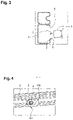
figure 3 , une première solution envisagée pour empêcher que le capteur 3 de recul ne vienne percuter la traverse arrière 2 lors de la survenance de petits chocs contre le pare-chocs arrière, a été de pratiquer une ouverture 4 dans la traverse 2, située devant ledit capteur 3. Selon un mode de réalisation particulier, le centre de cette ouverture 4 et le centre du capteur 3 sont alignés suivant un axe longitudinal X et horizontal du véhicule 1. Or cette solution n'est valable que lorsque le capteur 3 est déplacé horizontalement le long dudit axe comme cela est illustré par la flèche 5. En effet, lorsque par exemple le deuxième véhicule est surélevé par rapport au véhicule comprenant le capteur 3 de recul, les petits chocs contre le pare-chocs arrière ne sont plus réalisés suivant une direction horizontale mais suivant une direction oblique dirigée vers le bas, comme cela est illustré par la flèche 6. Dans ce cas, le capteur 3 a tendance à se déplacer vers le bas et risque de venir percuter un bord 7 de la traverse 2 délimitant l'ouverture 4. Le capteur 3 va donc être endommagé et il faudra le changer. - Un véhicule selon l'invention, met en oeuvre une deuxième solution pour empêcher que le capteur 3 de recul ne vienne percuter la traverse arrière 2 lors de la survenance de petits chocs contre le pare-chocs arrière dudit véhicule. Il s'agit de fixer à la traverse arrière 2 un élément de guidage 100 de manière à toujours orienter le déplacement du capteur 3 vers l'ouverture 4 de la traverse arrière 2, quelle que soit la direction des petits chocs produits sur le pare-chocs arrière.
- En se référant à la
figure 6 , l'élément de guidage 100 comprend une paroi latérale 101 divergente délimitant un canal interne possédant une première ouverture 102 d'extrémité et une deuxième ouverture d'extrémité103 élargie par rapport à ladite première ouverture102. De cette manière, la section transversale du canal interne augmente progressivement de la première ouverture 102 d'extrémité vers la deuxième ouverture d'extrémité 103. Les deux ouvertures 102, 103 d'extrémité sont chacune délimitées par deux bords rectilignes 104, 105, 106, 107 et par deux bords arrondis 108, 109, 110, 111 reliant lesdits deux bords rectilignes 104, 105, 106, 107, lesdites deux ouvertures 102, 103 étant coaxiales. - En se référant à la
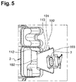
figure 5 , la paroi latérale 101 de l'élément de guidage 100 présente un bourrelet externe 112 situé du côté de la première extrémité 102, ledit bourrelet 112 prenant naissance sur le bord de la paroi 101 délimitant la première extrémité 102, et s'étendant sur moins de la moitié de la longueur de ladite paroi et préférentiellement sur moins du quart de ladite longueur. Une extrémité de ce bourrelet 112 située du côté de la deuxième ouverture extrémité 103 définit avec ladite paroi 101 un épaulement 113. Cet élément de guidage 100 est avantageusement réalisé dans un plastique dur, octroyant audit élément 100 une bonne tenue mécanique et une certaine propension à la déformation élastique. - L'élément de guidage 100 est fixé à la traverse 2 par clippage. En effet, cet élément 100 est introduit dans l'ouverture 4 de la traverse arrière 2 par la première ouverture d'extrémité 102. Il est ensuite enfoncé dans ladite ouverture 4 en se déformant élastiquement jusqu'à ce que l'épaulement 113 ait dépassé la paroi de ladite traverse 2 délimitant ladite ouverture. Le bourrelet 112, qui était comprimé se relâche derrière ladite paroi, piégeant alors l'élément de guidage 100 dans l'ouverture 4 de la traverse 2.
- En se référant à la
figure 4 , l'élément de guidage 100 est clipsé à la traverse arrière 2 de sorte que les bords rectilignes 104, 105, 106, 107 des deux ouvertures d'extrémité 102, 103 s'étendent parallèlement à un axe longitudinal de ladite traverse 2. La première ouverture d'extrémité 102 se retrouve devant la deuxième ouverture d'extrémité 103, et le capteur 3 de recul qui est solidarisé au pare-chocs arrière est placé en face et derrière ladite deuxième ouverture d'extrémité 103. Ainsi dans le cas de petits chocs répétés sur le pare-chocs arrière du véhicule 1, dus par exemple à un deuxième véhicule effectuant des manoeuvres pour se garer, le capteur 3 de recul va se déplacer vers l'avant et va systématiquement pénétrer dans la deuxième ouverture d'extrémité 103 de l'élément de guidage. En effet, les dimensions de ladite deuxième ouverture d'extrémité 103 et la disposition du capteur 3 de recul par rapport à ladite deuxième ouverture 103 font que le capteur 3 ne peut que pénétrer dans ladite deuxième ouverture d'extrémité 103, quelle que soit la direction du déplacement vers l'avant dudit capteur 3. Le capteur 3 peut alors, soit poursuivre sa progression vers l'avant à l'intérieur de l'élément de guidage 100 sans toucher la paroi latérale 101, soit venir au contact de ladite paroi latérale 101 puis coulisser le long de celle-ci en étant dirigé vers la première ouverture 102 d'extrémité dudit élément de guidage. En raison de la pente de la paroi latérale 101 de l'élément de guidage 100, la mise en contact du capteur 3 de recul avec ladite paroi 101 latérale s'effectue en douceur, sans générer le moindre choc, préservant ainsi l'intégrité dudit capteur 3. Le capteur 3 va alors se retrouver dans l'ouverture 4 de la traverse 2 sans jamais avoir impacté ladite traverse 2.
Claims (10)
- Véhicule (1) comprenant une traverse arrière (2) d'amortissement de choc, un pare-chocs arrière et un capteur (3) de recul, ledit capteur (3) étant supporté par le pare-chocs, caractérisé en ce que la traverse (2) possède une ouverture (4) située devant le capteur (3), et en ce qu'un élément de guidage (100) est fixé à la traverse (2), de manière à guider le déplacement du capteur (3) vers l'ouverture (4) dans le cas d'un choc accidentel à vitesse réduite provoqué sur le pare-chocs arrière par un objet extérieur.
- Véhicule selon la revendication 1, caractérisé en ce que l'élément de guidage (100) est une pièce solide comprenant une paroi latérale (101) délimitant une première ouverture (102) d'extrémité et une deuxième ouverture (103) d'extrémité élargie par rapport à ladite première ouverture (102), et en ce que ladite pièce (100) est positionnée sur la traverse (2) de sorte que la première ouverture (102) soit insérée dans l'ouverture (4) de ladite traverse (2) et la deuxième ouverture (103) soit placée en vis-à-vis du capteur (3).
- Véhicule selon la revendication 2, caractérisée en ce que les deux ouvertures (102, 103) de l'élément de guidage (100) sont chacune de forme oblongue et sont disposées l'une par rapport à l'autre en étant coaxiales.
- Véhicule selon la revendication 3 caractérisé en ce que chacune des deux ouvertures (102, 103) de l'élément de guidage (100) est délimitée par deux bords parallèles (104, 105, 106, 107) reliés entre eux par deux bords arrondis (108, 109, 110, 111).
- Véhicule selon l'une quelconque des revendications 3 ou 4, caractérisé en ce que les axes longitudinaux des deux ouvertures (102, 103) de l'élément de guidage (100) sont horizontaux.
- Véhicule selon l'une quelconque des revendications 1 à 5, caractérisé en ce que l'élément de guidage (100) est fixé à la traverse arrière par clippage.
- Véhicule selon l'une quelconque des revendications 1 à 6, caractérisé en ce que l'élément de guidage (100) est réalisé dans un plastique dur.
- Véhicule selon l'une quelconque des revendications 1 à 7, caractérisé en ce que le capteur (3) est fixé à une pièce support qui est elle-même solidarisée au pare-chocs arrière.
- Véhicule selon l'une quelconque des revendications 1 à 8, caractérisé en ce que la traverse arrière (2) est en tôle.
- Elément de guidage (100) pour la réalisation d'un véhicule (1) selon l'une quelconque des revendications 1 à 9, caractérisé en ce qu'il comprend une paroi latérale (101) délimitant une première ouverture (102) d'extrémité et une deuxième ouverture (103) d'extrémité élargie par rapport à ladite première ouverture (102), et en ce que lesdites deux ouvertures (102, 103) sont chacune de forme oblongue et sont disposées l'une par rapport en étant coaxiales.
Applications Claiming Priority (1)
| Application Number | Priority Date | Filing Date | Title |
|---|---|---|---|
| FR2002913A FR3108570B1 (fr) | 2020-03-25 | 2020-03-25 | Véhicule doté d’un capteur de recul sécurisé |
Publications (2)
| Publication Number | Publication Date |
|---|---|
| EP3885201A1 EP3885201A1 (fr) | 2021-09-29 |
| EP3885201B1 true EP3885201B1 (fr) | 2023-01-25 |
Family
ID=70918632
Family Applications (1)
| Application Number | Title | Priority Date | Filing Date |
|---|---|---|---|
| EP21159037.7A Active EP3885201B1 (fr) | 2020-03-25 | 2021-02-24 | Véhicule doté d'un capteur de recul sécurisé |
Country Status (2)
| Country | Link |
|---|---|
| EP (1) | EP3885201B1 (fr) |
| FR (1) | FR3108570B1 (fr) |
Families Citing this family (1)
| Publication number | Priority date | Publication date | Assignee | Title |
|---|---|---|---|---|
| CN115195652A (zh) * | 2022-07-29 | 2022-10-18 | 重庆长安汽车股份有限公司 | 一种汽车前碰撞横梁总成及其加工工艺 |
Family Cites Families (5)
| Publication number | Priority date | Publication date | Assignee | Title |
|---|---|---|---|---|
| DE102004037257A1 (de) * | 2004-07-31 | 2006-02-16 | Robert Bosch Gmbh | Einbauvorrichtung für einen Sensor |
| DE102005032082B3 (de) * | 2005-07-08 | 2006-12-21 | Siemens Ag | Trägerprofil für ein Sensorband zum Einbau in den Stoßfänger eines Kraftfahrzeugs und Sensoranordnung |
| US7607705B1 (en) * | 2008-10-27 | 2009-10-27 | Honda Motor Co., Ltd. | Rear bumper assembly with step garnish |
| KR20130071154A (ko) * | 2011-12-20 | 2013-06-28 | 현대모비스 주식회사 | 자동차의 센서 장치 |
| DE102015209904B4 (de) * | 2015-05-29 | 2020-02-13 | Volkswagen Aktiengesellschaft | Überwachungsvorrichtung für eine Sensoranordnung in einem Kraftfahrzeug |
-
2020
- 2020-03-25 FR FR2002913A patent/FR3108570B1/fr not_active Expired - Fee Related
-
2021
- 2021-02-24 EP EP21159037.7A patent/EP3885201B1/fr active Active
Also Published As
| Publication number | Publication date |
|---|---|
| FR3108570B1 (fr) | 2022-04-15 |
| FR3108570A1 (fr) | 2021-10-01 |
| EP3885201A1 (fr) | 2021-09-29 |
Similar Documents
| Publication | Publication Date | Title |
|---|---|---|
| EP3927570B1 (fr) | Dispositif de protection d'un organe automobile monté sous caisse | |
| EP0949092A1 (fr) | Pare-chocs de véhicule automobile | |
| FR3072925B1 (fr) | Dispositif d'amortissement de choc avant d'un vehicule automobile, comprenant un deflecteur d'air basculant et un amortisseur deformable fixes l'un a l''autre. | |
| FR3081820A1 (fr) | Diffuseur arriere mobile de vehicule a panneau escamotable | |
| EP3885201B1 (fr) | Véhicule doté d'un capteur de recul sécurisé | |
| EP1595755A1 (fr) | Support de butée d'un capot d'un véhicule automobile | |
| WO2020011550A1 (fr) | Guide d'air pour vehicule automobile realise d'une piece en materiau polymere expanse et comportant des zones d'absorption de choc | |
| EP3085554B1 (fr) | Ensemble de pare-chocs comportant un ecrou de remorquage et vehicule comportant un tel ensemble de pare-chocs | |
| EP0719671B1 (fr) | Dispositif d'indexation d'un bloc optique sur un élément de carrosserie de véhicule | |
| EP1755936B1 (fr) | Agencement pour roue de secours dans un vehicule automobile | |
| FR3105151A1 (fr) | Structure arriere de caisse de vehicule automobile a plancher polymere et support de batterie | |
| EP3676115B1 (fr) | Véhicule comportant un train arrière à déplacement longitudinal contrôlé en cas de choc arrière | |
| EP4001060B1 (fr) | Structure avant de vehicule automobile a gestion de choc frontal de faible recouvrement | |
| EP1568552B1 (fr) | Agencement d'un module fonctionnel sur une structure avant de véhicule | |
| FR2832110A1 (fr) | Poutre de pare-chocs a structure d'entretoise amelioree, module d'extremite longitudinale et vehicule automobile correspondants | |
| EP3199409B1 (fr) | Élément de moule de grille d'aération pour face avant de véhicule automobile | |
| EP2108570B1 (fr) | Partie avant de véhicule équipée d'un support de calandre biseauté | |
| EP3009305B1 (fr) | Poutre de pare-chocs automobile | |
| FR3024969A1 (fr) | Ensemble comportant une traverse de planche de bord et des supports pour fixer cette traverse a la caisse d' vehicule automobile | |
| FR3139524A1 (fr) | Dispositif pour l’assemblage d’un PARECHOC ARRIÈRE de VÉHICULE AUTOMOBILE | |
| WO2015052391A1 (fr) | Dispositif de fixation d'une traverse de poste de conduite d'un vehicule automobile | |
| FR3145326A1 (fr) | Ensemble pour pare-chocs avant de véhicule automobile | |
| FR3125490A1 (fr) | Véhicule automobile avec une structure de caisse comportant un pare-chocs avant | |
| FR3009256A1 (fr) | Voie basse pour vehicule automobile | |
| WO2016012659A1 (fr) | Dispositif de voie basse pour véhicule automobile |
Legal Events
| Date | Code | Title | Description |
|---|---|---|---|
| PUAI | Public reference made under article 153(3) epc to a published international application that has entered the european phase |
Free format text: ORIGINAL CODE: 0009012 |
|
| STAA | Information on the status of an ep patent application or granted ep patent |
Free format text: STATUS: THE APPLICATION HAS BEEN PUBLISHED |
|
| AK | Designated contracting states |
Kind code of ref document: A1 Designated state(s): AL AT BE BG CH CY CZ DE DK EE ES FI FR GB GR HR HU IE IS IT LI LT LU LV MC MK MT NL NO PL PT RO RS SE SI SK SM TR |
|
| RAP3 | Party data changed (applicant data changed or rights of an application transferred) |
Owner name: RENAULT S.A.S |
|
| STAA | Information on the status of an ep patent application or granted ep patent |
Free format text: STATUS: REQUEST FOR EXAMINATION WAS MADE |
|
| 17P | Request for examination filed |
Effective date: 20220323 |
|
| RBV | Designated contracting states (corrected) |
Designated state(s): AL AT BE BG CH CY CZ DE DK EE ES FI FR GB GR HR HU IE IS IT LI LT LU LV MC MK MT NL NO PL PT RO RS SE SI SK SM TR |
|
| RAP3 | Party data changed (applicant data changed or rights of an application transferred) |
Owner name: RENAULT S.A.S |
|
| GRAP | Despatch of communication of intention to grant a patent |
Free format text: ORIGINAL CODE: EPIDOSNIGR1 |
|
| STAA | Information on the status of an ep patent application or granted ep patent |
Free format text: STATUS: GRANT OF PATENT IS INTENDED |
|
| INTG | Intention to grant announced |
Effective date: 20220822 |
|
| GRAS | Grant fee paid |
Free format text: ORIGINAL CODE: EPIDOSNIGR3 |
|
| GRAA | (expected) grant |
Free format text: ORIGINAL CODE: 0009210 |
|
| STAA | Information on the status of an ep patent application or granted ep patent |
Free format text: STATUS: THE PATENT HAS BEEN GRANTED |
|
| AK | Designated contracting states |
Kind code of ref document: B1 Designated state(s): AL AT BE BG CH CY CZ DE DK EE ES FI FR GB GR HR HU IE IS IT LI LT LU LV MC MK MT NL NO PL PT RO RS SE SI SK SM TR |
|
| REG | Reference to a national code |
Ref country code: GB Ref legal event code: FG4D Free format text: NOT ENGLISH |
|
| REG | Reference to a national code |
Ref country code: CH Ref legal event code: EP |
|
| REG | Reference to a national code |
Ref country code: DE Ref legal event code: R096 Ref document number: 602021001288 Country of ref document: DE |
|
| REG | Reference to a national code |
Ref country code: AT Ref legal event code: REF Ref document number: 1545705 Country of ref document: AT Kind code of ref document: T Effective date: 20230215 Ref country code: IE Ref legal event code: FG4D Free format text: LANGUAGE OF EP DOCUMENT: FRENCH |
|
| REG | Reference to a national code |
Ref country code: LT Ref legal event code: MG9D |
|
| REG | Reference to a national code |
Ref country code: NL Ref legal event code: MP Effective date: 20230125 |
|
| REG | Reference to a national code |
Ref country code: AT Ref legal event code: MK05 Ref document number: 1545705 Country of ref document: AT Kind code of ref document: T Effective date: 20230125 |
|
| PG25 | Lapsed in a contracting state [announced via postgrant information from national office to epo] |
Ref country code: NL Free format text: LAPSE BECAUSE OF FAILURE TO SUBMIT A TRANSLATION OF THE DESCRIPTION OR TO PAY THE FEE WITHIN THE PRESCRIBED TIME-LIMIT Effective date: 20230125 |
|
| P01 | Opt-out of the competence of the unified patent court (upc) registered |
Effective date: 20230608 |
|
| PG25 | Lapsed in a contracting state [announced via postgrant information from national office to epo] |
Ref country code: RS Free format text: LAPSE BECAUSE OF FAILURE TO SUBMIT A TRANSLATION OF THE DESCRIPTION OR TO PAY THE FEE WITHIN THE PRESCRIBED TIME-LIMIT Effective date: 20230125 Ref country code: PT Free format text: LAPSE BECAUSE OF FAILURE TO SUBMIT A TRANSLATION OF THE DESCRIPTION OR TO PAY THE FEE WITHIN THE PRESCRIBED TIME-LIMIT Effective date: 20230525 Ref country code: NO Free format text: LAPSE BECAUSE OF FAILURE TO SUBMIT A TRANSLATION OF THE DESCRIPTION OR TO PAY THE FEE WITHIN THE PRESCRIBED TIME-LIMIT Effective date: 20230425 Ref country code: LV Free format text: LAPSE BECAUSE OF FAILURE TO SUBMIT A TRANSLATION OF THE DESCRIPTION OR TO PAY THE FEE WITHIN THE PRESCRIBED TIME-LIMIT Effective date: 20230125 Ref country code: LT Free format text: LAPSE BECAUSE OF FAILURE TO SUBMIT A TRANSLATION OF THE DESCRIPTION OR TO PAY THE FEE WITHIN THE PRESCRIBED TIME-LIMIT Effective date: 20230125 Ref country code: HR Free format text: LAPSE BECAUSE OF FAILURE TO SUBMIT A TRANSLATION OF THE DESCRIPTION OR TO PAY THE FEE WITHIN THE PRESCRIBED TIME-LIMIT Effective date: 20230125 Ref country code: ES Free format text: LAPSE BECAUSE OF FAILURE TO SUBMIT A TRANSLATION OF THE DESCRIPTION OR TO PAY THE FEE WITHIN THE PRESCRIBED TIME-LIMIT Effective date: 20230125 Ref country code: AT Free format text: LAPSE BECAUSE OF FAILURE TO SUBMIT A TRANSLATION OF THE DESCRIPTION OR TO PAY THE FEE WITHIN THE PRESCRIBED TIME-LIMIT Effective date: 20230125 |
|
| PG25 | Lapsed in a contracting state [announced via postgrant information from national office to epo] |
Ref country code: SE Free format text: LAPSE BECAUSE OF FAILURE TO SUBMIT A TRANSLATION OF THE DESCRIPTION OR TO PAY THE FEE WITHIN THE PRESCRIBED TIME-LIMIT Effective date: 20230125 Ref country code: PL Free format text: LAPSE BECAUSE OF FAILURE TO SUBMIT A TRANSLATION OF THE DESCRIPTION OR TO PAY THE FEE WITHIN THE PRESCRIBED TIME-LIMIT Effective date: 20230125 Ref country code: IS Free format text: LAPSE BECAUSE OF FAILURE TO SUBMIT A TRANSLATION OF THE DESCRIPTION OR TO PAY THE FEE WITHIN THE PRESCRIBED TIME-LIMIT Effective date: 20230525 Ref country code: GR Free format text: LAPSE BECAUSE OF FAILURE TO SUBMIT A TRANSLATION OF THE DESCRIPTION OR TO PAY THE FEE WITHIN THE PRESCRIBED TIME-LIMIT Effective date: 20230426 Ref country code: FI Free format text: LAPSE BECAUSE OF FAILURE TO SUBMIT A TRANSLATION OF THE DESCRIPTION OR TO PAY THE FEE WITHIN THE PRESCRIBED TIME-LIMIT Effective date: 20230125 |
|
| REG | Reference to a national code |
Ref country code: BE Ref legal event code: MM Effective date: 20230228 |
|
| REG | Reference to a national code |
Ref country code: DE Ref legal event code: R097 Ref document number: 602021001288 Country of ref document: DE |
|
| PG25 | Lapsed in a contracting state [announced via postgrant information from national office to epo] |
Ref country code: SM Free format text: LAPSE BECAUSE OF FAILURE TO SUBMIT A TRANSLATION OF THE DESCRIPTION OR TO PAY THE FEE WITHIN THE PRESCRIBED TIME-LIMIT Effective date: 20230125 Ref country code: RO Free format text: LAPSE BECAUSE OF FAILURE TO SUBMIT A TRANSLATION OF THE DESCRIPTION OR TO PAY THE FEE WITHIN THE PRESCRIBED TIME-LIMIT Effective date: 20230125 Ref country code: MC Free format text: LAPSE BECAUSE OF FAILURE TO SUBMIT A TRANSLATION OF THE DESCRIPTION OR TO PAY THE FEE WITHIN THE PRESCRIBED TIME-LIMIT Effective date: 20230125 Ref country code: LU Free format text: LAPSE BECAUSE OF NON-PAYMENT OF DUE FEES Effective date: 20230224 Ref country code: EE Free format text: LAPSE BECAUSE OF FAILURE TO SUBMIT A TRANSLATION OF THE DESCRIPTION OR TO PAY THE FEE WITHIN THE PRESCRIBED TIME-LIMIT Effective date: 20230125 Ref country code: DK Free format text: LAPSE BECAUSE OF FAILURE TO SUBMIT A TRANSLATION OF THE DESCRIPTION OR TO PAY THE FEE WITHIN THE PRESCRIBED TIME-LIMIT Effective date: 20230125 Ref country code: CZ Free format text: LAPSE BECAUSE OF FAILURE TO SUBMIT A TRANSLATION OF THE DESCRIPTION OR TO PAY THE FEE WITHIN THE PRESCRIBED TIME-LIMIT Effective date: 20230125 |
|
| PG25 | Lapsed in a contracting state [announced via postgrant information from national office to epo] |
Ref country code: SK Free format text: LAPSE BECAUSE OF FAILURE TO SUBMIT A TRANSLATION OF THE DESCRIPTION OR TO PAY THE FEE WITHIN THE PRESCRIBED TIME-LIMIT Effective date: 20230125 |
|
| PLBE | No opposition filed within time limit |
Free format text: ORIGINAL CODE: 0009261 |
|
| STAA | Information on the status of an ep patent application or granted ep patent |
Free format text: STATUS: NO OPPOSITION FILED WITHIN TIME LIMIT |
|
| REG | Reference to a national code |
Ref country code: IE Ref legal event code: MM4A |
|
| 26N | No opposition filed |
Effective date: 20231026 |
|
| PG25 | Lapsed in a contracting state [announced via postgrant information from national office to epo] |
Ref country code: SI Free format text: LAPSE BECAUSE OF FAILURE TO SUBMIT A TRANSLATION OF THE DESCRIPTION OR TO PAY THE FEE WITHIN THE PRESCRIBED TIME-LIMIT Effective date: 20230125 Ref country code: IE Free format text: LAPSE BECAUSE OF NON-PAYMENT OF DUE FEES Effective date: 20230224 |
|
| PG25 | Lapsed in a contracting state [announced via postgrant information from national office to epo] |
Ref country code: BE Free format text: LAPSE BECAUSE OF NON-PAYMENT OF DUE FEES Effective date: 20230228 |
|
| PG25 | Lapsed in a contracting state [announced via postgrant information from national office to epo] |
Ref country code: IT Free format text: LAPSE BECAUSE OF FAILURE TO SUBMIT A TRANSLATION OF THE DESCRIPTION OR TO PAY THE FEE WITHIN THE PRESCRIBED TIME-LIMIT Effective date: 20230125 |
|
| REG | Reference to a national code |
Ref country code: CH Ref legal event code: PL |
|
| PG25 | Lapsed in a contracting state [announced via postgrant information from national office to epo] |
Ref country code: CH Free format text: LAPSE BECAUSE OF NON-PAYMENT OF DUE FEES Effective date: 20240229 |
|
| PG25 | Lapsed in a contracting state [announced via postgrant information from national office to epo] |
Ref country code: CH Free format text: LAPSE BECAUSE OF NON-PAYMENT OF DUE FEES Effective date: 20240229 |
|
| PG25 | Lapsed in a contracting state [announced via postgrant information from national office to epo] |
Ref country code: BG Free format text: LAPSE BECAUSE OF FAILURE TO SUBMIT A TRANSLATION OF THE DESCRIPTION OR TO PAY THE FEE WITHIN THE PRESCRIBED TIME-LIMIT Effective date: 20230125 |
|
| PG25 | Lapsed in a contracting state [announced via postgrant information from national office to epo] |
Ref country code: BG Free format text: LAPSE BECAUSE OF FAILURE TO SUBMIT A TRANSLATION OF THE DESCRIPTION OR TO PAY THE FEE WITHIN THE PRESCRIBED TIME-LIMIT Effective date: 20230125 |
|
| PG25 | Lapsed in a contracting state [announced via postgrant information from national office to epo] |
Ref country code: CY Free format text: LAPSE BECAUSE OF FAILURE TO SUBMIT A TRANSLATION OF THE DESCRIPTION OR TO PAY THE FEE WITHIN THE PRESCRIBED TIME-LIMIT; INVALID AB INITIO Effective date: 20210224 |
|
| PG25 | Lapsed in a contracting state [announced via postgrant information from national office to epo] |
Ref country code: HU Free format text: LAPSE BECAUSE OF FAILURE TO SUBMIT A TRANSLATION OF THE DESCRIPTION OR TO PAY THE FEE WITHIN THE PRESCRIBED TIME-LIMIT; INVALID AB INITIO Effective date: 20210224 |
|
| PG25 | Lapsed in a contracting state [announced via postgrant information from national office to epo] |
Ref country code: TR Free format text: LAPSE BECAUSE OF FAILURE TO SUBMIT A TRANSLATION OF THE DESCRIPTION OR TO PAY THE FEE WITHIN THE PRESCRIBED TIME-LIMIT Effective date: 20230125 |
|
| PGFP | Annual fee paid to national office [announced via postgrant information from national office to epo] |
Ref country code: GB Payment date: 20260220 Year of fee payment: 6 |
|
| PGFP | Annual fee paid to national office [announced via postgrant information from national office to epo] |
Ref country code: DE Payment date: 20260218 Year of fee payment: 6 |
|
| PGFP | Annual fee paid to national office [announced via postgrant information from national office to epo] |
Ref country code: FR Payment date: 20260218 Year of fee payment: 6 |