EP3885175A1 - Hybrid drive device - Google Patents
Hybrid drive device Download PDFInfo
- Publication number
- EP3885175A1 EP3885175A1 EP20738128.6A EP20738128A EP3885175A1 EP 3885175 A1 EP3885175 A1 EP 3885175A1 EP 20738128 A EP20738128 A EP 20738128A EP 3885175 A1 EP3885175 A1 EP 3885175A1
- Authority
- EP
- European Patent Office
- Prior art keywords
- transmitting shaft
- shaft
- end portion
- drive device
- radial bearing
- Prior art date
- Legal status (The legal status is an assumption and is not a legal conclusion. Google has not performed a legal analysis and makes no representation as to the accuracy of the status listed.)
- Granted
Links
Images


Classifications
-
- H—ELECTRICITY
- H02—GENERATION; CONVERSION OR DISTRIBUTION OF ELECTRIC POWER
- H02K—DYNAMO-ELECTRIC MACHINES
- H02K7/00—Arrangements for handling mechanical energy structurally associated with dynamo-electric machines, e.g. structural association with mechanical driving motors or auxiliary dynamo-electric machines
- H02K7/006—Structural association of a motor or generator with the drive train of a motor vehicle
-
- B—PERFORMING OPERATIONS; TRANSPORTING
- B60—VEHICLES IN GENERAL
- B60K—ARRANGEMENT OR MOUNTING OF PROPULSION UNITS OR OF TRANSMISSIONS IN VEHICLES; ARRANGEMENT OR MOUNTING OF PLURAL DIVERSE PRIME-MOVERS IN VEHICLES; AUXILIARY DRIVES FOR VEHICLES; INSTRUMENTATION OR DASHBOARDS FOR VEHICLES; ARRANGEMENTS IN CONNECTION WITH COOLING, AIR INTAKE, GAS EXHAUST OR FUEL SUPPLY OF PROPULSION UNITS IN VEHICLES
- B60K6/00—Arrangement or mounting of plural diverse prime-movers for mutual or common propulsion, e.g. hybrid propulsion systems comprising electric motors and internal combustion engines
- B60K6/20—Arrangement or mounting of plural diverse prime-movers for mutual or common propulsion, e.g. hybrid propulsion systems comprising electric motors and internal combustion engines the prime-movers consisting of electric motors and internal combustion engines, e.g. HEVs
- B60K6/22—Arrangement or mounting of plural diverse prime-movers for mutual or common propulsion, e.g. hybrid propulsion systems comprising electric motors and internal combustion engines the prime-movers consisting of electric motors and internal combustion engines, e.g. HEVs characterised by apparatus, components or means specially adapted for HEVs
- B60K6/40—Arrangement or mounting of plural diverse prime-movers for mutual or common propulsion, e.g. hybrid propulsion systems comprising electric motors and internal combustion engines the prime-movers consisting of electric motors and internal combustion engines, e.g. HEVs characterised by apparatus, components or means specially adapted for HEVs characterised by the assembly or relative disposition of components
-
- B—PERFORMING OPERATIONS; TRANSPORTING
- B60—VEHICLES IN GENERAL
- B60K—ARRANGEMENT OR MOUNTING OF PROPULSION UNITS OR OF TRANSMISSIONS IN VEHICLES; ARRANGEMENT OR MOUNTING OF PLURAL DIVERSE PRIME-MOVERS IN VEHICLES; AUXILIARY DRIVES FOR VEHICLES; INSTRUMENTATION OR DASHBOARDS FOR VEHICLES; ARRANGEMENTS IN CONNECTION WITH COOLING, AIR INTAKE, GAS EXHAUST OR FUEL SUPPLY OF PROPULSION UNITS IN VEHICLES
- B60K6/00—Arrangement or mounting of plural diverse prime-movers for mutual or common propulsion, e.g. hybrid propulsion systems comprising electric motors and internal combustion engines
- B60K6/20—Arrangement or mounting of plural diverse prime-movers for mutual or common propulsion, e.g. hybrid propulsion systems comprising electric motors and internal combustion engines the prime-movers consisting of electric motors and internal combustion engines, e.g. HEVs
- B60K6/22—Arrangement or mounting of plural diverse prime-movers for mutual or common propulsion, e.g. hybrid propulsion systems comprising electric motors and internal combustion engines the prime-movers consisting of electric motors and internal combustion engines, e.g. HEVs characterised by apparatus, components or means specially adapted for HEVs
- B60K6/38—Arrangement or mounting of plural diverse prime-movers for mutual or common propulsion, e.g. hybrid propulsion systems comprising electric motors and internal combustion engines the prime-movers consisting of electric motors and internal combustion engines, e.g. HEVs characterised by apparatus, components or means specially adapted for HEVs characterised by the driveline clutches
- B60K6/387—Actuated clutches, i.e. clutches engaged or disengaged by electric, hydraulic or mechanical actuating means
-
- B—PERFORMING OPERATIONS; TRANSPORTING
- B60—VEHICLES IN GENERAL
- B60K—ARRANGEMENT OR MOUNTING OF PROPULSION UNITS OR OF TRANSMISSIONS IN VEHICLES; ARRANGEMENT OR MOUNTING OF PLURAL DIVERSE PRIME-MOVERS IN VEHICLES; AUXILIARY DRIVES FOR VEHICLES; INSTRUMENTATION OR DASHBOARDS FOR VEHICLES; ARRANGEMENTS IN CONNECTION WITH COOLING, AIR INTAKE, GAS EXHAUST OR FUEL SUPPLY OF PROPULSION UNITS IN VEHICLES
- B60K6/00—Arrangement or mounting of plural diverse prime-movers for mutual or common propulsion, e.g. hybrid propulsion systems comprising electric motors and internal combustion engines
- B60K6/20—Arrangement or mounting of plural diverse prime-movers for mutual or common propulsion, e.g. hybrid propulsion systems comprising electric motors and internal combustion engines the prime-movers consisting of electric motors and internal combustion engines, e.g. HEVs
- B60K6/22—Arrangement or mounting of plural diverse prime-movers for mutual or common propulsion, e.g. hybrid propulsion systems comprising electric motors and internal combustion engines the prime-movers consisting of electric motors and internal combustion engines, e.g. HEVs characterised by apparatus, components or means specially adapted for HEVs
- B60K6/40—Arrangement or mounting of plural diverse prime-movers for mutual or common propulsion, e.g. hybrid propulsion systems comprising electric motors and internal combustion engines the prime-movers consisting of electric motors and internal combustion engines, e.g. HEVs characterised by apparatus, components or means specially adapted for HEVs characterised by the assembly or relative disposition of components
- B60K6/405—Housings
-
- B—PERFORMING OPERATIONS; TRANSPORTING
- B60—VEHICLES IN GENERAL
- B60K—ARRANGEMENT OR MOUNTING OF PROPULSION UNITS OR OF TRANSMISSIONS IN VEHICLES; ARRANGEMENT OR MOUNTING OF PLURAL DIVERSE PRIME-MOVERS IN VEHICLES; AUXILIARY DRIVES FOR VEHICLES; INSTRUMENTATION OR DASHBOARDS FOR VEHICLES; ARRANGEMENTS IN CONNECTION WITH COOLING, AIR INTAKE, GAS EXHAUST OR FUEL SUPPLY OF PROPULSION UNITS IN VEHICLES
- B60K6/00—Arrangement or mounting of plural diverse prime-movers for mutual or common propulsion, e.g. hybrid propulsion systems comprising electric motors and internal combustion engines
- B60K6/20—Arrangement or mounting of plural diverse prime-movers for mutual or common propulsion, e.g. hybrid propulsion systems comprising electric motors and internal combustion engines the prime-movers consisting of electric motors and internal combustion engines, e.g. HEVs
- B60K6/42—Arrangement or mounting of plural diverse prime-movers for mutual or common propulsion, e.g. hybrid propulsion systems comprising electric motors and internal combustion engines the prime-movers consisting of electric motors and internal combustion engines, e.g. HEVs characterised by the architecture of the hybrid electric vehicle
- B60K6/48—Parallel type
-
- B—PERFORMING OPERATIONS; TRANSPORTING
- B60—VEHICLES IN GENERAL
- B60L—PROPULSION OF ELECTRICALLY-PROPELLED VEHICLES; SUPPLYING ELECTRIC POWER FOR AUXILIARY EQUIPMENT OF ELECTRICALLY-PROPELLED VEHICLES; ELECTRODYNAMIC BRAKE SYSTEMS FOR VEHICLES IN GENERAL; MAGNETIC SUSPENSION OR LEVITATION FOR VEHICLES; MONITORING OPERATING VARIABLES OF ELECTRICALLY-PROPELLED VEHICLES; ELECTRIC SAFETY DEVICES FOR ELECTRICALLY-PROPELLED VEHICLES
- B60L50/00—Electric propulsion with power supplied within the vehicle
- B60L50/10—Electric propulsion with power supplied within the vehicle using propulsion power supplied by engine-driven generators, e.g. generators driven by combustion engines
- B60L50/16—Electric propulsion with power supplied within the vehicle using propulsion power supplied by engine-driven generators, e.g. generators driven by combustion engines with provision for separate direct mechanical propulsion
-
- F—MECHANICAL ENGINEERING; LIGHTING; HEATING; WEAPONS; BLASTING
- F16—ENGINEERING ELEMENTS AND UNITS; GENERAL MEASURES FOR PRODUCING AND MAINTAINING EFFECTIVE FUNCTIONING OF MACHINES OR INSTALLATIONS; THERMAL INSULATION IN GENERAL
- F16D—COUPLINGS FOR TRANSMITTING ROTATION; CLUTCHES; BRAKES
- F16D13/00—Friction clutches
- F16D13/58—Details
- F16D13/60—Clutching elements
- F16D13/64—Clutch-plates; Clutch-lamellae
- F16D13/68—Attachments of plates or lamellae to their supports
- F16D13/683—Attachments of plates or lamellae to their supports for clutches with multiple lamellae
-
- F—MECHANICAL ENGINEERING; LIGHTING; HEATING; WEAPONS; BLASTING
- F16—ENGINEERING ELEMENTS AND UNITS; GENERAL MEASURES FOR PRODUCING AND MAINTAINING EFFECTIVE FUNCTIONING OF MACHINES OR INSTALLATIONS; THERMAL INSULATION IN GENERAL
- F16D—COUPLINGS FOR TRANSMITTING ROTATION; CLUTCHES; BRAKES
- F16D25/00—Fluid-actuated clutches
- F16D25/06—Fluid-actuated clutches in which the fluid actuates a piston incorporated in, i.e. rotating with the clutch
- F16D25/062—Fluid-actuated clutches in which the fluid actuates a piston incorporated in, i.e. rotating with the clutch the clutch having friction surfaces
- F16D25/063—Fluid-actuated clutches in which the fluid actuates a piston incorporated in, i.e. rotating with the clutch the clutch having friction surfaces with clutch members exclusively moving axially
- F16D25/0635—Fluid-actuated clutches in which the fluid actuates a piston incorporated in, i.e. rotating with the clutch the clutch having friction surfaces with clutch members exclusively moving axially with flat friction surfaces, e.g. discs
- F16D25/0638—Fluid-actuated clutches in which the fluid actuates a piston incorporated in, i.e. rotating with the clutch the clutch having friction surfaces with clutch members exclusively moving axially with flat friction surfaces, e.g. discs with more than two discs, e.g. multiple lamellae
-
- F—MECHANICAL ENGINEERING; LIGHTING; HEATING; WEAPONS; BLASTING
- F16—ENGINEERING ELEMENTS AND UNITS; GENERAL MEASURES FOR PRODUCING AND MAINTAINING EFFECTIVE FUNCTIONING OF MACHINES OR INSTALLATIONS; THERMAL INSULATION IN GENERAL
- F16H—GEARING
- F16H57/00—General details of gearing
- F16H57/02—Gearboxes; Mounting gearing therein
- F16H57/021—Shaft support structures, e.g. partition walls, bearing eyes, casing walls or covers with bearings
-
- F—MECHANICAL ENGINEERING; LIGHTING; HEATING; WEAPONS; BLASTING
- F16—ENGINEERING ELEMENTS AND UNITS; GENERAL MEASURES FOR PRODUCING AND MAINTAINING EFFECTIVE FUNCTIONING OF MACHINES OR INSTALLATIONS; THERMAL INSULATION IN GENERAL
- F16H—GEARING
- F16H57/00—General details of gearing
- F16H57/04—Features relating to lubrication or cooling or heating
- F16H57/042—Guidance of lubricant
- F16H57/0421—Guidance of lubricant on or within the casing, e.g. shields or baffles for collecting lubricant, tubes, pipes, grooves, channels or the like
- F16H57/0424—Lubricant guiding means in the wall of or integrated with the casing, e.g. grooves, channels, holes
-
- F—MECHANICAL ENGINEERING; LIGHTING; HEATING; WEAPONS; BLASTING
- F16—ENGINEERING ELEMENTS AND UNITS; GENERAL MEASURES FOR PRODUCING AND MAINTAINING EFFECTIVE FUNCTIONING OF MACHINES OR INSTALLATIONS; THERMAL INSULATION IN GENERAL
- F16H—GEARING
- F16H57/00—General details of gearing
- F16H57/04—Features relating to lubrication or cooling or heating
- F16H57/042—Guidance of lubricant
- F16H57/043—Guidance of lubricant within rotary parts, e.g. axial channels or radial openings in shafts
-
- F—MECHANICAL ENGINEERING; LIGHTING; HEATING; WEAPONS; BLASTING
- F16—ENGINEERING ELEMENTS AND UNITS; GENERAL MEASURES FOR PRODUCING AND MAINTAINING EFFECTIVE FUNCTIONING OF MACHINES OR INSTALLATIONS; THERMAL INSULATION IN GENERAL
- F16H—GEARING
- F16H57/00—General details of gearing
- F16H57/04—Features relating to lubrication or cooling or heating
- F16H57/0467—Elements of gearings to be lubricated, cooled or heated
- F16H57/0469—Bearings or seals
- F16H57/0471—Bearing
-
- F—MECHANICAL ENGINEERING; LIGHTING; HEATING; WEAPONS; BLASTING
- F16—ENGINEERING ELEMENTS AND UNITS; GENERAL MEASURES FOR PRODUCING AND MAINTAINING EFFECTIVE FUNCTIONING OF MACHINES OR INSTALLATIONS; THERMAL INSULATION IN GENERAL
- F16H—GEARING
- F16H57/00—General details of gearing
- F16H57/04—Features relating to lubrication or cooling or heating
- F16H57/0467—Elements of gearings to be lubricated, cooled or heated
- F16H57/0469—Bearings or seals
- F16H57/0472—Seals
-
- H—ELECTRICITY
- H02—GENERATION; CONVERSION OR DISTRIBUTION OF ELECTRIC POWER
- H02K—DYNAMO-ELECTRIC MACHINES
- H02K7/00—Arrangements for handling mechanical energy structurally associated with dynamo-electric machines, e.g. structural association with mechanical driving motors or auxiliary dynamo-electric machines
- H02K7/003—Couplings; Details of shafts
-
- H—ELECTRICITY
- H02—GENERATION; CONVERSION OR DISTRIBUTION OF ELECTRIC POWER
- H02K—DYNAMO-ELECTRIC MACHINES
- H02K7/00—Arrangements for handling mechanical energy structurally associated with dynamo-electric machines, e.g. structural association with mechanical driving motors or auxiliary dynamo-electric machines
- H02K7/08—Structural association with bearings
- H02K7/083—Structural association with bearings radially supporting the rotary shaft at both ends of the rotor
-
- H—ELECTRICITY
- H02—GENERATION; CONVERSION OR DISTRIBUTION OF ELECTRIC POWER
- H02K—DYNAMO-ELECTRIC MACHINES
- H02K7/00—Arrangements for handling mechanical energy structurally associated with dynamo-electric machines, e.g. structural association with mechanical driving motors or auxiliary dynamo-electric machines
- H02K7/10—Structural association with clutches, brakes, gears, pulleys or mechanical starters
- H02K7/108—Structural association with clutches, brakes, gears, pulleys or mechanical starters with friction clutches
-
- H—ELECTRICITY
- H02—GENERATION; CONVERSION OR DISTRIBUTION OF ELECTRIC POWER
- H02K—DYNAMO-ELECTRIC MACHINES
- H02K9/00—Arrangements for cooling or ventilating
- H02K9/19—Arrangements for cooling or ventilating for machines with closed casing and closed-circuit cooling using a liquid cooling medium, e.g. oil
-
- B—PERFORMING OPERATIONS; TRANSPORTING
- B60—VEHICLES IN GENERAL
- B60K—ARRANGEMENT OR MOUNTING OF PROPULSION UNITS OR OF TRANSMISSIONS IN VEHICLES; ARRANGEMENT OR MOUNTING OF PLURAL DIVERSE PRIME-MOVERS IN VEHICLES; AUXILIARY DRIVES FOR VEHICLES; INSTRUMENTATION OR DASHBOARDS FOR VEHICLES; ARRANGEMENTS IN CONNECTION WITH COOLING, AIR INTAKE, GAS EXHAUST OR FUEL SUPPLY OF PROPULSION UNITS IN VEHICLES
- B60K6/00—Arrangement or mounting of plural diverse prime-movers for mutual or common propulsion, e.g. hybrid propulsion systems comprising electric motors and internal combustion engines
- B60K6/20—Arrangement or mounting of plural diverse prime-movers for mutual or common propulsion, e.g. hybrid propulsion systems comprising electric motors and internal combustion engines the prime-movers consisting of electric motors and internal combustion engines, e.g. HEVs
- B60K6/42—Arrangement or mounting of plural diverse prime-movers for mutual or common propulsion, e.g. hybrid propulsion systems comprising electric motors and internal combustion engines the prime-movers consisting of electric motors and internal combustion engines, e.g. HEVs characterised by the architecture of the hybrid electric vehicle
- B60K6/48—Parallel type
- B60K2006/4825—Electric machine connected or connectable to gearbox input shaft
-
- B—PERFORMING OPERATIONS; TRANSPORTING
- B60—VEHICLES IN GENERAL
- B60K—ARRANGEMENT OR MOUNTING OF PROPULSION UNITS OR OF TRANSMISSIONS IN VEHICLES; ARRANGEMENT OR MOUNTING OF PLURAL DIVERSE PRIME-MOVERS IN VEHICLES; AUXILIARY DRIVES FOR VEHICLES; INSTRUMENTATION OR DASHBOARDS FOR VEHICLES; ARRANGEMENTS IN CONNECTION WITH COOLING, AIR INTAKE, GAS EXHAUST OR FUEL SUPPLY OF PROPULSION UNITS IN VEHICLES
- B60K6/00—Arrangement or mounting of plural diverse prime-movers for mutual or common propulsion, e.g. hybrid propulsion systems comprising electric motors and internal combustion engines
- B60K6/20—Arrangement or mounting of plural diverse prime-movers for mutual or common propulsion, e.g. hybrid propulsion systems comprising electric motors and internal combustion engines the prime-movers consisting of electric motors and internal combustion engines, e.g. HEVs
- B60K6/50—Architecture of the driveline characterised by arrangement or kind of transmission units
- B60K6/54—Transmission for changing ratio
- B60K6/547—Transmission for changing ratio the transmission being a stepped gearing
-
- B—PERFORMING OPERATIONS; TRANSPORTING
- B60—VEHICLES IN GENERAL
- B60Y—INDEXING SCHEME RELATING TO ASPECTS CROSS-CUTTING VEHICLE TECHNOLOGY
- B60Y2400/00—Special features of vehicle units
- B60Y2400/42—Clutches or brakes
- B60Y2400/424—Friction clutches
- B60Y2400/4244—Friction clutches of wet type, e.g. using multiple lamellae
-
- F—MECHANICAL ENGINEERING; LIGHTING; HEATING; WEAPONS; BLASTING
- F16—ENGINEERING ELEMENTS AND UNITS; GENERAL MEASURES FOR PRODUCING AND MAINTAINING EFFECTIVE FUNCTIONING OF MACHINES OR INSTALLATIONS; THERMAL INSULATION IN GENERAL
- F16H—GEARING
- F16H57/00—General details of gearing
- F16H57/02—Gearboxes; Mounting gearing therein
- F16H2057/02034—Gearboxes combined or connected with electric machines
-
- F—MECHANICAL ENGINEERING; LIGHTING; HEATING; WEAPONS; BLASTING
- F16—ENGINEERING ELEMENTS AND UNITS; GENERAL MEASURES FOR PRODUCING AND MAINTAINING EFFECTIVE FUNCTIONING OF MACHINES OR INSTALLATIONS; THERMAL INSULATION IN GENERAL
- F16H—GEARING
- F16H57/00—General details of gearing
- F16H57/02—Gearboxes; Mounting gearing therein
- F16H2057/02039—Gearboxes for particular applications
- F16H2057/02043—Gearboxes for particular applications for vehicle transmissions
-
- Y—GENERAL TAGGING OF NEW TECHNOLOGICAL DEVELOPMENTS; GENERAL TAGGING OF CROSS-SECTIONAL TECHNOLOGIES SPANNING OVER SEVERAL SECTIONS OF THE IPC; TECHNICAL SUBJECTS COVERED BY FORMER USPC CROSS-REFERENCE ART COLLECTIONS [XRACs] AND DIGESTS
- Y02—TECHNOLOGIES OR APPLICATIONS FOR MITIGATION OR ADAPTATION AGAINST CLIMATE CHANGE
- Y02T—CLIMATE CHANGE MITIGATION TECHNOLOGIES RELATED TO TRANSPORTATION
- Y02T10/00—Road transport of goods or passengers
- Y02T10/60—Other road transportation technologies with climate change mitigation effect
- Y02T10/62—Hybrid vehicles
-
- Y—GENERAL TAGGING OF NEW TECHNOLOGICAL DEVELOPMENTS; GENERAL TAGGING OF CROSS-SECTIONAL TECHNOLOGIES SPANNING OVER SEVERAL SECTIONS OF THE IPC; TECHNICAL SUBJECTS COVERED BY FORMER USPC CROSS-REFERENCE ART COLLECTIONS [XRACs] AND DIGESTS
- Y02—TECHNOLOGIES OR APPLICATIONS FOR MITIGATION OR ADAPTATION AGAINST CLIMATE CHANGE
- Y02T—CLIMATE CHANGE MITIGATION TECHNOLOGIES RELATED TO TRANSPORTATION
- Y02T10/00—Road transport of goods or passengers
- Y02T10/60—Other road transportation technologies with climate change mitigation effect
- Y02T10/64—Electric machine technologies in electromobility
-
- Y—GENERAL TAGGING OF NEW TECHNOLOGICAL DEVELOPMENTS; GENERAL TAGGING OF CROSS-SECTIONAL TECHNOLOGIES SPANNING OVER SEVERAL SECTIONS OF THE IPC; TECHNICAL SUBJECTS COVERED BY FORMER USPC CROSS-REFERENCE ART COLLECTIONS [XRACs] AND DIGESTS
- Y02—TECHNOLOGIES OR APPLICATIONS FOR MITIGATION OR ADAPTATION AGAINST CLIMATE CHANGE
- Y02T—CLIMATE CHANGE MITIGATION TECHNOLOGIES RELATED TO TRANSPORTATION
- Y02T10/00—Road transport of goods or passengers
- Y02T10/60—Other road transportation technologies with climate change mitigation effect
- Y02T10/7072—Electromobility specific charging systems or methods for batteries, ultracapacitors, supercapacitors or double-layer capacitors
-
- Y—GENERAL TAGGING OF NEW TECHNOLOGICAL DEVELOPMENTS; GENERAL TAGGING OF CROSS-SECTIONAL TECHNOLOGIES SPANNING OVER SEVERAL SECTIONS OF THE IPC; TECHNICAL SUBJECTS COVERED BY FORMER USPC CROSS-REFERENCE ART COLLECTIONS [XRACs] AND DIGESTS
- Y02—TECHNOLOGIES OR APPLICATIONS FOR MITIGATION OR ADAPTATION AGAINST CLIMATE CHANGE
- Y02T—CLIMATE CHANGE MITIGATION TECHNOLOGIES RELATED TO TRANSPORTATION
- Y02T10/00—Road transport of goods or passengers
- Y02T10/60—Other road transportation technologies with climate change mitigation effect
- Y02T10/72—Electric energy management in electromobility
Definitions
- the present disclosure relates to a hybrid drive device including an engine, a rotary electric machine, a transmission coupled to the rotary electric machine, and a clutch that couples the engine and the rotary electric machine and that releases the connection of the two.
- a hybrid drive device of this type including a case for housing a rotary electric machine and a clutch, and a rotor support member that supports a rotor and that is rotatably supported by the case is known (for example, see Patent Documents 1).
- the case of this hybrid drive device includes a case wall extended in a radial direction on the transmission side and a shaft support portion that is fixed to the case wall so as to be extended in an axial direction.
- the shaft support portion includes a first tubular member that rotatably supports the rotor support member in the radial direction and a second tubular member that is fixed to an inner side of the first tubular member.
- a first oil passage extending in the axial direction is formed between the first tubular member and the second tubular member in the radial direction. Further, a second oil passage that is sealed by sealing members disposed on both sides in the axial direction is formed between an outer peripheral surface of the first tubular member and an inner peripheral surface of the rotor support member.
- the second oil passage communicates with an engagement oil chamber (working oil chamber) of the clutch via an oil passage formed in the rotor support member, and communicates with the first oil passage via a through hole formed in the first tubular member.
- a tubular coupling member is disposed in the shaft support portion (second tubular member), and two radial bearings are disposed at intervals in the axial direction between an inner peripheral surface of the second tubular member and an outer peripheral surface of the coupling member.
- a flange member that is coupled to a torque converter via a flex plate is spline-fitted to an end portion on the transmission side of the coupling member, and a flange portion that is coupled to the rotor support member via splines is formed in an end portion on the engine side of the coupling member.
- the end portion on the transmission side of the coupling member is formed in a tubular shape, and an end portion of an input member driven by the engine is inserted into the end portion on the transmission side of the coupling member so as to be rotatable.
- Patent Document 1 Japanese Unexamined Patent Application Publication No. 2017-177884 ( JP 2017-177884 A )
- the coupling member for coupling the rotor support member to the torque converter is supported in the radial direction and is supported so as to be rotatable, by the shaft support portion (second tubular member) fixed to the case, via two radial bearings.
- the shaft support portion second tubular member fixed to the case, via two radial bearings.
- the main object of the present disclosure is to shorten the axial length of the hybrid drive device while suppressing the shaft runout of the transmission shaft that transmits power from the rotor of the rotary electric machine to the transmission.
- a hybrid drive device of the present disclosure includes a rotary electric machine having a stator and a rotor, a transmission coupled to the rotary electric machine, a clutch that couples an engine and the rotary electric machine and that releases a connection of the two, and a case for housing the rotary electric machine and the clutch, and the hybrid drive device includes: a first transmitting shaft coupled to an output shaft of the engine; and second transmitting shaft that transmits power from the rotor of the rotary electric machine to the transmission, in which the first transmitting shaft includes a first end portion on the engine side and a second end portion on the transmission side, and is supported in a radial direction between the first and second end portions in an axial direction by the case via a first radial bearing, the second end of the first transmitting shaft is inserted into an end portion on the engine side of the second transmitting shaft formed in a tubular shape, a second radial bearing that supports the second transmitting shaft in the radial direction is disposed between an outer peripheral surface of the second end portion of the first
- the first transmitting shaft that is coupled to the output shaft of the engine is supported in the radial direction between the first end portion on the engine side and the second end portion on the transmission side in the axial direction by the case via the first radial bearing.
- the second end portion of the first transmitting shaft is inserted into the end portion on the engine side of the second transmitting shaft formed in a tubular shape, and the second radial bearing that supports the second transmitting shaft in the radial direction is disposed between the outer peripheral surface of the second end portion of the first transmitting shaft and the inner peripheral surface of the end portion of the second transmitting shaft.
- the second transmitting shaft is supported in the radial direction by the shaft support portion provided in the case on the transmission side of the end portion via the third radial bearing. That is, the second transmitting shaft is supported in the radial direction by the case via the second radial bearing, the first transmitting shaft, and the first radial bearing on the engine side, and is supported in the radial direction by the shaft support portion of the case via the third radial bearing on the transmission side.
- the shaft support portion can be shortened, and another member can be disposed in the surplus space made as a result of the shaft support portion being shortened. As a result, it is possible to shorten the axial length of the hybrid drive device while suppressing the shaft runout of the second transmitting shaft that transmits the power from the rotor of the rotary electric machine to the transmission.
- FIG. 1 is a schematic configuration diagram showing a hybrid drive device 10 of the present disclosure.
- FIG. 2 and FIG. 3 are enlarged views showing the hybrid drive device 10.
- the hybrid drive device 10 is mounted on a vehicle 1 and generates a disturbance force for traveling, and as shown in FIG. 1 , includes an engine 11, a motor generator (rotary electric machine) MG, a first transmitting shaft 141 coupled to the engine 11, a second transmitting shaft 142 to which power is transmitted from the motor generator MG, a clutch K0 that couples the first and second transmitting shafts 141, 142 and that releases the connection of the two, and a power transmitting device 15.
- the hybrid drive device 10 may be mounted on a rear-wheel drive vehicle as illustrated, may be mounted on a front-wheel drive vehicle, or may be mounted on a four-wheel drive vehicle including a transfer coupled to the power transmitting device 15.
- the engine 11 is an internal combustion engine that converts a reciprocating motion of a piston (not shown) in accordance with the combustion of a mixture of hydrocarbon fuel such as gasoline or light oil and air into a rotational motion of a crankshaft (output shaft) 12.
- the crankshaft 12 of the engine 11 is coupled to the first transmitting shaft 141 via an annular coupling member 123 and a damper mechanism 13.
- the damper mechanism 13 includes an input element coupled to the crankshaft 12 via the coupling member 123, an output element coupled to the first transmitting shaft 141, and a plurality of coil springs (elastic bodies) that transmits a torque between the input element and the output element and that dampens a torsional vibration.
- the motor generator MG is a synchronous generator motor (three-phase alternating current motor), and transmits and receives electric power to and from a power storage device (battery, not shown) via an inverter that is not shown.
- the motor generator MG operates as an electric motor that is driven by electric power from the power storage device to generate a drive torque, and outputs a regenerative braking torque when the vehicle 1 is braked.
- the motor generator MG also operates as a generator that generates electric power by using at least a part of the power from the engine 11 that is operated under load.
- the motor generator MG includes a stator 20 and a rotor 30 housed in a motor case 8.
- the motor case 8 includes a housing 80 having one end open and a cover 88 fixed to the housing 80 so as to cover the one end.
- the housing 80 of the motor case 8 is a generally bottomed tubular body in which one end in the axial direction, that is, an end portion on the engine 11 side is opened, and the other end in the axial direction, that is, an end portion on the power transmitting device 15 side is closed.
- the housing 80 is formed by casting an aluminum alloy, and includes a tubular outer shell portion 81 and an end wall (wall portion) 82 that closes the other end of the outer shell portion 81.
- a front side flange portion 81f having a plurality of bolt holes is formed on one end (front end) of the outer shell portion 81 of the housing 80, that is, on an outer periphery on an open end side.
- the front side flange portion 81f is fastened (fixed) to an engine block of the engine 11 via a plurality of bolts that is not shown and that is each inserted into a corresponding bolt hole.
- the other end portion of the outer shell portion 81 protrudes from the end wall 82 toward the opposite side from the front side flange portion 81f, and a rear side flange portion 81r having a plurality of bolt holes is formed on an outer periphery of the other end (rear end) of the outer shell portion 81.
- the rear side flange portion 81r is fastened (fixed) to an end portion (front end) of a transmission case 150 (see FIG. 1 ) of the power transmitting device 15 via a plurality of bolts that is not shown and that is each inserted into the corresponding bolt hole.
- a tubular shaft support portion 85 having a through hole is provided in a center portion of the end wall 82 of the housing 80, and the second transmitting shaft 142 protrudes from the through hole of the tubular support portion 85 toward the power transmitting device 15 side.
- the shaft support portion 85 may be formed integrally with the end wall 82, or the shaft support portion 85 separate from the housing 80 may be fixed to the end wall 82.
- a flange portion 142f (see FIG. 2 ) is formed on an end portion of the second transmitting shaft 142 protruding from the end wall 82, and an inner peripheral portion of a flex plate 145 is fastened (fixed) to the flange portion 142f via a plurality of bolts not shown.
- a seal member 90 is disposed in a clearance between the second transmitting shaft 142 and the shaft support portion 85.
- the cover 88 of the motor case 8 is a disk-shaped member formed by casting an aluminum alloy. As shown in FIG. 3 , the cover 88 includes a flange portion 88f having a plurality of bolt holes arranged at intervals along the outer periphery, a through hole through which the first transmitting shaft 141 is inserted, and a plurality of boss portions 88b each having a screw hole and that is formed at intervals in the circumferential direction. A seal member 91 is disposed in a clearance between the cover 88 and the first transmitting shaft 141 inserted through the through hole of the cover 88.
- the stator 20 includes an annular stator core 21 and a stator coil 22 wound around the stator core 21.
- the stator core 21 is integrally formed by stacking a plurality of electromagnetic steel plates formed in an annular shape by press working and coupling the plurality of electromagnetic steel plates in a stacking direction, for example.
- a plurality of bolt holes extending in the axial direction is formed in the stator core 21, and a bolt 87 is inserted into each bolt hole.
- Each bolt 87 is screwed into the screw hole of the corresponding boss portion 88b of the cover 88 and thus, the stator 20 is fixed to the cover 88.
- the cover 88 to which the stator 20 is fixed is fixed to the housing 80 via a plurality of bolts 89 so that the stator 20 is surrounded by the outer shell portion 81 and a coil end 22b faces the end wall 82.
- the stator 20 is non-rotatably fixed to the motor case 8
- the cover 88 forms an end wall portion of the motor case 8 extending in the radial direction so as to face the motor generator MG and the clutch K0 on the engine 11 side.
- the cover 88 is fixed to the housing 80 so as to be close to the front side flange portion 81f, that is, a fastening portion (fixing portion) between the housing 80 and the engine block. This makes it possible to fix the cover 88 and the stator 20 to the engine block and the housing 80 more firmly.
- the stator coil 22 includes three coils of a U phase, a V phase and a W phase, and includes a coil end 22a protruding from an end surface on the damper mechanism 13 side (left side in FIG. 3 ) in the axial direction of the stator core 21, and a coil end 22b protruding from an end surface on the power transmitting device 15 side (right side in FIG. 3 ).
- One end portion of the U phase, V phase, and W phase coils protrudes in the axial direction from the coil end 22b and is used as a terminal 22c of each phase.
- the terminal 22c of each phase is electrically coupled to an inverter (not shown) via a bus bar (not shown) of the V phase, the U phase, or the W phase corresponding to each terminal 22c.
- the rotor 30 includes a rotor core 31, end plates 32, 33 disposed on both sides of the rotor core 31 in the axial direction, and a rotor support member 40 for holding the rotor core 31 and the like.
- the rotor core 31 is formed by stacking a plurality of electromagnetic steel plates formed in an annular shape by press working, for example. Further, a plurality of through holes (not shown) each extending in the axial direction at intervals in the circumferential direction is formed in the rotor core 31, and a permanent magnet is embedded in each through hole.
- the rotor support member 40 includes an annular outer side half portion 41, an annular inner side half portion 45 fixed to the outer side half portion 41, and an annular plate member (annular member) 50. Both the outer side half portion 41 and the inner side half portion 45 are formed by machining a forged body made of a steel material (made of an iron alloy), for example.
- the plate member 50 is also made of steel material.
- the outer side half portion 41 includes a cylindrical outer tubular portion (tubular support portion) 42 in which the rotor core 31 is fixed to an outer peripheral portion, an annular flange portion 43 extended radially outward from one end (left end in FIG.
- the rotor core 31 is fixed to the outer tubular portion 42 of the rotor support member 40 by shrink fitting processing in a state in which the end plates 32, 33 are disposed on both sides in the axial direction. Further, the end plate 33 positioned on the opposite side of the flange portion 43 is fixed to the outer tubular portion 42 by swaging or the like. However, the rotor core 31 may be fixed to the outer tubular portion 42 by press fitting.
- the inner side half portion 45 includes: an annular wall portion 46 extended in the radial direction; an inner tubular portion 47 that has a tubular shape and that is extended from an inner peripheral portion of the annular wall portion 46 to one side (left side in FIG. 3 ) in the axial direction; a cylindrical supported portion 48 extended from the annular wall portion 46 to the other side (right side in FIG. 3 ), on an outer radial side of the inner tubular portion 47; and a short tubular piston support portion 49 extended from the annular wall portion 46 to one side in the axial direction, on an outer radial side of the supported portion 48.
- At least one recess portion 46a recessed to the piston support portion 49 side is formed so as to at least partially overlap with the piston support portion 49 when viewed in the axial direction of the rotor 30.
- the recess portion 46a is formed in the annular wall portion 46 in order to correct the imbalance of the entire rotor 30 after the rotor core 31 and the end plates 32, 33 are fixed to the rotor support member 40.
- an outer periphery of the annular wall portion 46 is fixed to an inner periphery of the radial protruding portion 44 of the outer side half portion 41 by welding. Further, an outer peripheral portion of the plate member 50 is fastened to the flange portion 43 of the rotor support member 40 (outer side half portion 41) by a plurality of bolts 43b so as to face the annular wall portion 46 at a distance in the axial direction.
- the plate member 50 is fixed to the flange portion 43 in a state in which a surface of the outer peripheral portion is in contact with an end surface (left side end surface in FIG. 3 ) on the opposite side of the flange portion 43 from the rotor 30 side.
- an axial protruding portion 43p that has a short cylindrical (annular) shape is formed in the flange portion 43 so as to protrude in the axial direction from an outer peripheral portion of the end surface, with which the plate member 50 is in contact, to the opposite side (engine 11 side) from the rotor core 31 side.
- the outer peripheral surface of the plate member 50 is supported in the radial direction by the axial protruding portion 43p of the flange portion 43.
- a plurality of the axial protruding portions 43p may be formed on the outer peripheral portion of the end surface of the flange portion 43 at intervals in the circumferential direction.
- an outer peripheral surface of the supported portion 48 of the rotor support member 40 (inner side half portion 45) is supported in the radial direction and is supported so as to be rotatable by the motor case 8 via a radial bearing Brr (ball bearing in the present embodiment) held by the end wall 82 of the housing 80.
- the movement of the rotor support member 40 toward a speed change mechanism 17 side is restricted by the housing 80, that is, the case 8 via the radial bearing Brr.
- the inner peripheral portion of the plate member 50 is supported in the radial direction and is supported so as to be rotatable by the cover 88 of the motor case 8 via a radial bearing Brf (an outer side radial bearing, in the present embodiment, a ball bearing).
- the rotor 30 is supported in the radial direction by the motor case 8 via the radial bearing Brf.
- the inner tubular portion 47 of the rotor support member 40 includes a spline formed on an inner peripheral surface of a tip end portion (an end portion on the engine 11 side), and is always coupled (fixed) to the second transmitting shaft 142 via the spline.
- the clutch K0 couples the first transmitting shaft 141, that is, the crankshaft 12 of the engine 11, and the second transmitting shaft 142, that is, the rotor 30 of the motor generator MG, and releases the connection of the two.
- the clutch K0 is a multi-plate friction type hydraulic clutch that uses the rotor support member 40 of the rotor 30 that is always coupled to the second transmitting shaft 142 as a clutch drum, and is disposed in the motor case 8, that is, on the inner radial side of the rotor 30. As shown in FIG.
- the clutch K0 in addition to the rotor support member 40 serving as a clutch drum, the clutch K0 includes a clutch hub 61 that is disposed between the annular wall portion 46 of the rotor support member 40 and the plate member 50 in the axial direction and that is always coupled (fixed) to the first transmitting shaft 141, a plurality of friction plates (second friction engagement plates) 63, a plurality of separator plates (first friction engagement plates) 64 and backing plates 65 that are alternately arranged with the friction plates 63, a snap ring 66, a piston 67, a plurality of return springs SP, and a cancel plate (cancel oil chamber defining member) 68.
- a clutch hub 61 that is disposed between the annular wall portion 46 of the rotor support member 40 and the plate member 50 in the axial direction and that is always coupled (fixed) to the first transmitting shaft 141
- a plurality of friction plates (second friction engagement plates) 63 a plurality of separator plates (first friction engagement plates) 64 and backing
- the clutch hub 61 includes a tubular portion 61a and an annular wall portion 61b extended radially inward from one end of the tubular portion 61a.
- Splines 61s are formed on an outer peripheral surface of the tubular portion 61a, and an inner periphery of the annular wall portion 61b is fixed to the first transmitting shaft 141.
- splines 42s are formed on the inner peripheral surface of the outer tubular portion 42 of the rotor support member 40 serving as the clutch drum so as to be positioned closer to the flange portion 43 side than the radial protruding portion 44.
- the friction plate 63 is an annular member to which a friction material is attached to both surfaces, and an outer peripheral portion of each friction plate 63 is fitted to the splines 42s (inner peripheral portion) of the outer tubular portion 42. Further, the backing plate 65 is fitted to the splines 42s of the outer tubular portion 42 so as to be able to come into contact with the friction plate 63 farthest from the piston 67 among the plurality of friction plates 63.
- the separator plate 64 is an annular member in which both surfaces are formed to be smooth, and an inner peripheral portion of each separator plate 64 is fitted to the splines 61s (outer peripheral portion) formed in the tubular portion 61a of the clutch hub 61.
- annular recess portion 42a that is recessed radially outward is formed in the splines 42s of the outer tubular portion 42.
- the snap ring 66 is attached (fitted) to the annular recess portion 42a, and the movement of the backing plate 65, etc. in the axial direction (the movement in a direction away from the piston 67) is restricted by the snap ring 66.
- the annular recess portion 42a when viewed in the radial direction of the rotor 30, the annular recess portion 42a is formed in the splines 42s so as to overlap in the axial direction with a part of the flange portion 43 (including the annular plate disposed between the flange portion 43 and the end plate 32), more specifically, an end surface (an end surface in contact with the end plate 32) on the rotor 30 side of the flange portion 43.
- the flange portion 43 is extended radially outward from one end in the axial direction of the outer tubular portion 42 of the rotor support member 40, and the radial protruding portion 44 and the annular wall portion 46 are extended radially inward from the other end side of the center portion in the axial direction of the outer tubular portion 42.
- the rotor core 31 is fixed to the outer tubular portion 42 by shrink fitting processing or press fitting, according to the experiments and analysis by the present inventors, it was found that a relatively large stress acts on the outer tubular portion 42 from the rotor core 31 between the flange portion 43 and the radial protruding portion 44 in the axial direction.
- the annular recess portion 42a is formed between the flange portion 43 of the outer tubular portion 42 and the radial protruding portion 44 in the axial direction, the stress from the rotor core 31 is concentrated in the annular recess portion 42a and there is a possibility that the durability of the outer tubular portion 42 as well as the rotor support member 40 as a whole is decreased.
- the annular recess portion 42a is formed in the outer tubular portion 42 so as to overlap with a part of the flange portion 43 (the end surface on the rotor 30 side) in the axial direction when viewed in the radial direction of the rotor 30.
- the annular recess portion 42a can be formed in the outer tubular portion 42 so as to overlap with at least a part of the flange portion 43.
- the plate member 50 is fastened to the flange portion 43 by the bolt 43b, since a thickness (axial length) of the flange portion 43 is ensured to some extent, it is possible to further improve the durability of the rotor support member 40 by making the end surface on the radial protruding portion 44 side of the annular recess portion 42a substantially flush with the end surface on the rotor 30 side of the flange portion 43, when viewed in the radial direction of the rotor 30.
- the piston 67 includes an annular pressure receiving portion 67a, a tubular supported portion 67b extended from an outer periphery of the pressure receiving portion 67a to the clutch hub 61 side in the axial direction, and a pressing portion 67c formed radially outward of the supported portion 67b, and the piston 67 is disposed between the annular wall portion 46 of the rotor support member 40 and the plate member 50 in the axial direction.
- An inner peripheral surface of the pressure receiving portion 67a of the piston 67 is supported so as to be movable in the axial direction by an outer peripheral surface of the inner tubular portion 47 of the rotor support member 40 serving as a clutch drum via the seal member.
- the outer peripheral surface of the pressure receiving portion 67a is movably supported in the axial direction by the inner peripheral surface of the piston support portion 49 of the rotor support member 40 via a seal member, and an engagement oil chamber 69a of the clutch K0 is defined between the annular wall portion 46 of the rotor support member 40 and the pressure receiving portion 67a of the piston 67.
- a plurality of recess portions (grooves) loosely fitted in the splines 42s of the outer tubular portion 42 of the rotor support member 40 is formed in the outer peripheral portion of the pressing portion 67c at intervals in the circumferential direction.
- the cancel plate 68 is an annular member disposed on an opposite side of the piston 67 from the annular wall portion 46 of the rotor support member 40.
- An inner peripheral portion of the cancel plate 68 is fixed to the inner tubular portion 47 of the rotor support member 40 by using a snap ring.
- an outer peripheral surface of the cancel plate 68 movably supports an inner peripheral surface of the supported portion 67b of the piston 67 via a seal member, in the axial direction.
- a centrifugal hydraulic pressure cancel chamber 69b for canceling a centrifugal hydraulic pressure generated in the engagement oil chamber 69a is defined between the pressure receiving portion 67a of the piston 67 and the cancel plate 68.
- the plurality of return springs (coil springs) SP is disposed at intervals in the circumferential direction between the pressure receiving portion 67a of the piston 67 and the cancel plate 68 in the axial direction.
- Each return spring SP urges the piston 67 to a side away from the friction plate 63 and the separator plate 64.
- the power transmitting device 15 includes units such as a torque converter (fluid transmission device) 16 having a torque amplification function, a lockup clutch CL, the speed change mechanism (automatic transmission) 17, a mechanical oil pump 18, and a hydraulic control device 19 that adjust working oil pressure, the transmission case 150 that houses the speed change mechanism 17, etc.
- the torque converter 16 includes a front cover serving as an input member that is always coupled to the second transmitting shaft 142 via the flex plate 145 (see FIGS. 1 and 2 ), a pump impeller fixed to the front cover, and a turbine runner coupled to an input shaft 17i of the speed change mechanism 17, and a stator that rectifies the flow of the working oil from the turbine runner to the pump impeller so as to amplify the torque.
- the power transmitting device 15 may include a fluid coupling that has no stator, instead of the torque converter 16.
- the lockup clutch CL couples the front cover and the input shaft 17i of the speed change mechanism 17 and releases the connection of the two.
- the speed change mechanism 17 is, for example, a 4-speed to 10-speed type multi-speed transmission including an output shaft 17o, a plurality of planetary gears, a plurality of clutches and a plurality of brakes (engagement elements for shifting), in addition to the input shaft 17i.
- the speed change mechanism 17 shifts a power transmitted from at least one of the engine 11 and the motor generator MG to the input shaft 17i via the second transmitting shaft 142 and either one of the torque converter 16 and the lockup clutch CL, in a plurality of stages, to output from the output shaft 17o to left and right drive wheels DW via a differential gear DF.
- the speed change mechanism 17 may be a dual clutch transmission or a mechanical continuously variable transmission.
- the torque converter 16 and the lockup clutch CL may be omitted from the power transmitting device 15.
- the speed change mechanism 17 may be coupled to the motor generator MG (the rotor support member 40 or the second transmitting shaft 142) via a clutch different from the clutch K0.
- the oil pump 18 is a gear pump or a vane pump coupled to the pump impeller of the torque converter 16 via a winding transmitting mechanism, and is disposed on a shaft different from the input shaft 17i of the speed change mechanism 17.
- the oil pump 18 is driven by the power from the second transmitting shaft 142 via the winding transmitting mechanism, and sucks the working oil (ATF) stored in a working oil storage portion (not shown) to pressure-feed to the hydraulic control device 19.
- the hydraulic control device 19 includes a valve body in which a plurality of oil passages is formed, a plurality of regulator valves, a plurality of linear solenoid valves, and the like.
- the hydraulic control device 19 adjusts the hydraulic pressure (working oil) from the oil pump 18 and supplies the hydraulic pressure to the torque converter 16, the lockup clutch CL, the clutches and the brakes of the speed change mechanism 17.
- the transmission case 150 is a cast product made of an aluminum alloy.
- the hybrid drive device 10 includes a second hydraulic control device 70 that supplies hydraulic pressure to the clutch K0.
- the hydraulic control device 70 is attached to a lower portion of the motor case 8 and adjusts the hydraulic pressure from the oil pump 18 to supply the hydraulic pressure to the engagement oil chamber 69a of the clutch K0 and the like.
- the working oil drained from the hydraulic control device 70 is supplied to the centrifugal hydraulic pressure cancel chamber 69b of the clutch K0 via a radial oil passage 84 formed in the end wall 82 (shaft support portion 85), the axial oil passage L2 and a radial oil passage L4 formed in the second transmitting shaft 142, and the oil hole 47a formed in the inner tubular portion 47 of the rotor support member 40 so as to be side by side with an oil hole 47b in the axial direction.
- the hydraulic control device 70 may be omitted from the hybrid drive device 10, and in this case, the clutch K0 may be supplied with the hydraulic pressure from the hydraulic control device 19 of the power transmitting device 15. Further, the centrifugal hydraulic pressure cancel chamber 69b may be omitted from the clutch K0.
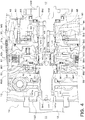
- the first transmitting shaft 141 includes a first end portion 141a on the engine 11 side (left side in FIG. 4 ), a second end portion 141b on the speed change mechanism 17 side (right side in FIG. 4 ), and a disc-shaped expanded radius portion 141e formed between the first and second end portions 141a, 141b in the axial direction.
- the first end portion 141a has an outer peripheral surface having columnar surface shape
- the second end portion 141b is formed in a cylindrical shape (tubular shape) having a radius smaller than that of the first end portion 141a, as illustrated.
- the expanded radius portion 141e of the first transmitting shaft 141 is formed to have a larger radius than that of the first and second end portions 141a, 141b, and is adjacent to the second end portion 141b on the engine 11 side. That is, the second end portion 141b protrudes from an end surface of the expanded radius portion 141e on the speed change mechanism 17 side to the opposite side of the first end portion 141a.
- annular flange portion 141f is extended from the expanded radius portion 141e of the first transmitting shaft 141.
- the flange portion 141f is extended radially outward and toward the speed change mechanism 17 side, from the outer peripheral portion of the expanded radius portion 141e so as to surround a part (about half of the expanded radius portion 141e side) of the second end portion 141b on the speed change mechanism 17 side of the plate member 50 of the rotor support member 40.
- an inner peripheral portion of a surface of the flange portion 141f on the speed change mechanism 17 side is formed in a conical surface shape so that a radius decreases from the speed change mechanism 17 side toward the engine 11 side.
- the inner periphery of the annular wall portion 61b of the clutch hub 61 is fixed to an outer peripheral portion of the flange portion 141f by welding. Further, a thrust bearing (outer side thrust bearing) Btm that supports the first transmitting shaft 141 in the axial direction is disposed between the flange portion 141f and the inner peripheral portion of the plate member 50 facing the flange portion 141f.
- An end portion 142a of the second transmitting shaft 142 on the engine 11 side is formed in a cylindrical shape (tubular shape) having an outer radius smaller than an outer radius of the expanded radius portion 141e of the first transmitting shaft 141 and an inner radius larger than an outer radius of the second end portion 141b of the first transmitting shaft 141.
- An internal space of the end portion 142a communicates with an axial oil passage L2 of the second transmitting shaft 142.
- splines into which the splines of the inner tubular portion 47 of the rotor support member 40 are fitted are formed on an outer peripheral surface of the end portion 142a.
- the first end portion 141a of the first transmitting shaft 141 is supported in the radial direction by the crankshaft 12 of the engine 11 via the coupling member 123 that couples the crankshaft 12 and the damper mechanism 13, and a radial bearing Br0 (a fourth radial bearing, a ball bearing in the present embodiment). Further, the expanded radius portion 141e of the first transmitting shaft 141 is supported in the radial direction, between the first and second end portions 141a, 141b in the axial direction, by the cover 88 that is an end wall portion of the motor case 8 on the engine 11 side via a radial bearing Br1 (a first radial bearing or an inner side radial bearing). As shown in FIG.
- the cover 88 includes a cylindrical first tubular portion 881 that protrudes from an inner periphery thereof toward the speed change mechanism 17 side so as to define a through hole through which the first transmitting shaft 141 is inserted.
- the radial bearing Br1 is disposed between an inner peripheral surface of the first tubular portion 881 and an outer peripheral surface of the expanded radius portion 141e of the first transmitting shaft 141 so as to be positioned on the speed change mechanism 17 side (right side in the figure) than the seal member 91 described above.
- the radial bearing Br1 is a cylindrical roller bearing including a cup that is press-fitted into the first tubular portion 881 of the cover 88.
- the second end portion 141b of the first transmitting shaft 141 is inserted into the end portion 142a that is formed in a tubular shape and that is on the engine 11 side of the second transmitting shaft 142, and a radial bearing Br2 (a second radial bearing or an intermediate radial bearing) that supports the second transmitting shaft 142 in the radial direction is disposed between the outer peripheral surface of the second end portion 141b of the first transmitting shaft 141 and the inner peripheral surface of the end portion 142a of the second transmitting shaft 142 (therebetween in the radial direction).
- the radial bearing Br2 is a cylindrical roller bearing including a cup that is press-fitted into the end portion 142a of the second transmitting shaft 142.
- the radial bearing Br2 overlaps at least partially with the clutch hub 61 fixed to the outer peripheral portion of the flange portion 141f of the first transmitting shaft 141, in the axial direction.
- a thrust bearing (inner side thrust bearing) Bt1 that supports the first and second transmitting shafts 141, 142 in the axial direction is disposed.
- a thrust bearing that includes a single cage is adopted as the thrust bearing Bt1 in order to ensure oil permeability.
- a clearance is formed between an inner peripheral portion of the flange portion 141f of the first transmitting shaft 141 and the end portion 142a of the second transmitting shaft 142.
- an internal space communicating with the axial oil passage L2 is defined between the end surface of the second end portion 141b of the first transmitting shaft 141 and an inner end surface in which the axial oil passage L2 in the end portion 142a of the second transmitting shaft 142 opens.
- the first transmitting shaft 141 includes a plurality of inner side oil holes (first oil holes) hi formed in the second end portion 141b at intervals in the circumferential direction, and a plurality of outer side oil holes (second oil holes) ho each formed at intervals in the circumferential direction so as to pass through a vicinity of a base end portion of the flange portion 141f of the first transmitting shaft 141.
- the plurality of inner side oil holes hi is each opened on an inner peripheral surface of the second end portion 141b, is opened between the radial bearing Br2 and the thrust bearing Bt1 on the outer peripheral surface of the second end portion 141b and the thrust bearing Bt1 in the axial direction, and forms an oil passage with an internal space that is opened at the end surface of the second end portion 141b.
- each inner side oil hole hi is formed obliquely so as to approach the engine 11 from the outer peripheral surface toward the inner peripheral surface of the second end portion 141b of the first transmitting shaft 141.
- a plurality of outer side oil holes o is formed so as to at least partially overlap with the radial bearing Br1 and the thrust bearing Bt1 in the axial direction when viewed in the radial direction, and is extended in the radial direction.
- the second transmitting shaft 142 is supported in the radial direction by the shaft support portion 85 that is provided in the housing 80 (end wall 82) of the motor case 8 on the speed change mechanism 17 side of the end portion 142a via a radial bearing (third radial bearing) Br3.
- the radial bearing Br3 is a cylindrical roller bearing including a cup that is press-fitted in the shaft support portion 85 of the housing 80.
- a thrust bearing Bt2 that supports the second transmitting shaft 142 in the axial direction is disposed between the flange portion 142f of the second transmitting shaft 142 and the end wall 82 of the housing 80 in the axial direction.
- the thrust bearing Bt2 includes two cages.
- the shaft support portion 85 of the housing 80 is formed in the end wall 82 so as to have an axial length of approximately half an axial length of a part (cylindrical part) of the second transmitting shaft 142 excluding the flange portion 142f. Further, the inner tubular portion 47 of the rotor support member 40 is fitted to the second transmitting shaft 142 so as to be positioned closer to the engine 11 than the shaft support portion 85.
- splines on the inner peripheral surface of the inner tubular portion 47 are fitted to splines formed on the outer peripheral surface of the end portion 142a of the second transmitting shaft 142, and a snap ring that restricts the axial movement of the inner tubular portion 47, that is, the rotor support member 40 is attached to the end portion 142a.
- the rotor support member 40 that is, the rotor 30 of the motor generator MG is always coupled to the second transmitting shaft 142
- a fixing portion (spline fitting portion) f (see dotted line in FIG. 4 ) of the inner tubular portion 47, that is, the rotor support member 40 and the second transmitting shaft 142 is at least partially overlapped with the radial bearing Br2 in the axial direction when seen in the radial direction.
- the cover 88 of the motor case 8 includes a cylindrical second tubular portion 882 protruding in the axial direction toward the speed change mechanism 17 so as to surround the first tubular portion 881.
- the second tubular portion 882 has an inner radius larger than an outer radius of the first tubular portion 881.
- the plate member 50 of the rotor support member 40 includes a cylindrical tubular portion 51 that protrudes in the axial direction from the inner periphery thereof toward the engine 11.
- the tubular portion 51 of the plate member 50 has an inner radius larger than the outer radius of the first tubular portion 881 of the cover 88 and has an outer radius smaller than an inner radius of the second tubular portion 882.
- An outer race of the radial bearing Brf (ball bearing) is press-fitted into the second tubular portion 882 so as not to come into contact with a surface (inner side surface) of the cover 88 on the speed change mechanism 17 side, and the tubular portion 51 of the plate member 50 is fitted in an inner race of the radial bearing Brf.
- the radial bearing Brf is disposed between an outer peripheral surface of the tubular portion 51 of the plate member 50 and an inner peripheral surface of the second tubular portion 882 of the cover 88, and the plate member 50 is supported by the cover 88 via the radial bearing Brf so as to be rotatable and is also supported in the radial direction.
- the inner radius of the tubular portion 51 of the plate member 50 is larger than the outer radius of the first tubular portion 881 of the cover 88.
- an annular clearance a is formed between the outer peripheral surface of the first tubular portion 881 and the inner peripheral surface of the tubular portion 51 of the plate member 50.
- a plurality of (for example, three in the present embodiment) oil holes h1 is formed in the first tubular portion 881 of the cover 88 at intervals in the circumferential direction.
- Each oil hole h1 is opened on the outer peripheral surface of the first tubular portion 881 and is opened on the inner peripheral surface of the first tubular portion 881 between the radial bearing Br1 and the seal member 91 in the axial direction. That is, each oil hole h1 communicates with a space in the axial direction between the clearance a, the radial bearing Br1, and the seal member 91.
- an end surface of the first tubular portion 881 of the cover 88 faces the flange portion 141f of the first transmitting shaft 141 at a distance, and an annular clearance b that communicates with the clearance a is formed between the end surface of the first tubular portion 881 and the flange portion 141f, as shown in FIG. 4 .
- the above clearance b also communicates with an inner peripheral portion of the space in which the thrust bearing Btm is disposed.
- the end surface of the second tubular portion 882 of the cover 88 faces the plate member 50 at a distance, and an annular clearance c is formed between the end surface of the second tubular portion 882 (and the end surfaces of the inner race and outer race of the radial bearing Brf) and the plate member 50.
- the second tubular portion 882 includes a plurality of (for example, two in the present embodiment) oil grooves g and a plurality of (for example, two in the present embodiment) oil holes h2.
- the plurality of oil grooves g is spaced at intervals in the circumferential direction on the inner peripheral surface of the second tubular portion 882 so that at least one oil groove g is positioned on an upper side in the motor case 8 and at least one oil groove g is positioned on a lower side in the motor case 8, and each communicates with the clearance c and a space defined between an inner side surface of the cover 88 and the radial bearing Brf. As shown in FIGS.
- the plurality of oil holes h2 is formed so that at least one oil hole h2 is positioned on the upper side in the motor case 8 and at least one oil hole h2 is positioned on the lower side in the motor case 8, and each opens at the outer peripheral surface of the second tubular portion 882 and opens at a bottom surface (inner peripheral surface) of the corresponding oil groove g.
- the cover 88 includes a pair of oil collecting guides (protruding portions) 885 protruding from the inner side surface so as to be included in an upper side half region in the motor case 8.
- the pair of oil collecting guides 885 is formed on the inner side surface of the cover 88 so that the oil collecting guides 885 are separated from each other (are opened to the left and right) from the vicinity of an uppermost portion of the second tubular portion 882 in the motor case 8 toward an outer radial side.
- the base end portion of each oil collecting guide 885 protrudes to the vicinity of the end surface of the second tubular portion 882.
- one oil hole h2 is disposed between the base end portions of the pair of oil collecting guides 885.
- the first transmitting shaft 141 coupled to the crankshaft 12 of the engine 11 is supported in the radial direction by the cover 88 of the motor case 8 via the radial bearing (first radial bearing) Br1, between the first end portion 141a on the engine 11 side and the second end portion 141b on the speed change mechanism 17 side in the axial direction.
- the second end portion 141b of the first transmitting shaft 141 is inserted into the end portion 142a that is formed in a tubular shape and that is on the engine 11 side of the second transmitting shaft 142, and a radial bearing (a second radial bearing) Br2 that supports the second transmitting shaft 142 in the radial direction is disposed between the outer peripheral surface of the second end portion 141b of the first transmitting shaft 141 and the inner peripheral surface of the end portion 142a of the second transmitting shaft 142.
- the second transmitting shaft 142 is supported in the radial direction by the shaft support portion 85 that is provided in the housing 80 of the motor case 8 on the speed change mechanism 17 side of the end portion 142a via a radial bearing (third radial bearing) Br3.
- the second transmitting shaft 142 is supported in the radial direction by the motor case 8 (cover 88) via the radial bearing Br2, the first transmitting shaft 141, and the radial bearing Br1 on the engine 11 side, and is supported in the radial direction by the shaft support portion 85 of the motor case 8 (housing 80) via the radial bearing Br3 on the speed change mechanism 17 side.
- the shaft support portion 85 of the motor case 8 (housing 80) via the radial bearing Br3 on the speed change mechanism 17 side.
- the shaft support portion 85 of the motor case 8 since it is not necessary to extend the shaft support portion 85 of the motor case 8 to the engine 11 side so as to support the radial bearing Br2, the shaft support portion 85 can be shortened, and another member, that is, the rotor support member 40 (inner tubular portion 47) can be disposed in the surplus space made as a result of the shaft support portion 85 being shortened. As a result, it is possible to shorten the axial length of the hybrid drive device 10 while suppressing a shaft runout of the second transmitting shaft 142.
- the inner tubular portion 47 of the rotor support member 40 is fitted to the second transmitting shaft 142 on the engine 11 side of the shaft support portion 85 of the motor case 8, and the fixing portion f of the inner tubular portion 47 (rotor support member 40) and the second transmitting shaft 142 is at least partially overlapped in the axial direction with the radial bearing Br2 when seen in the radial direction.
- the axial length of the hybrid drive device 10 can be further shortened by effectively utilizing the surplus space made by shortening the shaft support portion 85 of the motor case 8.
- first end portion 141a of the first transmitting shaft 141 is supported in the radial direction by the coupling member 123 that couples the crankshaft 12 of the engine 11 and the damper mechanism 13 via the radial bearing (fourth radial bearing) Br0.
- the first transmitting shaft 141 includes the expanded radius portion 141e having a radius larger than that of the second end portion 141b adjacent to the second end portion 141b on the engine 11 side, and the expanded radius portion 141e is supported in the radial direction by the cover 88 of the motor case 8 via the radial bearing Br1. This makes it possible to support both the first and second transmitting shafts 141, 142 so that a shaft runout does not occur for the two.
- the annular flange portion 141f is extended radially outward from the expanded radius portion 141e of the first transmitting shaft 141 so as to surround at least a part of the second end portion 141b on the speed change mechanism 17 side.
- the clutch hub 61 of the clutch K0 is fixed to the outer peripheral portion of the flange portion 141f so as to at least partially overlap with the radial bearing Br2 in the axial direction when viewed in the radial direction.
- the motor case 8 of the hybrid drive device 10 includes the cover 88 serving as the end wall portion extending so as to face the motor generator MG and the clutch K0 on the engine 11 side, and the rotor support member 40 includes the plate member (annular member) 50 that faces the cover 88.
- the cover 88 includes the first tubular portion 881 that protrudes in the axial direction from the inner periphery toward the speed change mechanism 17, and the second tubular portion 882 that protrudes in the axial direction toward the speed change mechanism 17 so as to surround the first tubular portion 881, and the plate member 50 of the rotor support member 40 includes the tubular portion 51 that protrudes in the axial direction from the inner periphery toward the engine 11.
- the radial bearing (inner side radial bearing) Br1 for supporting the first transmitting shaft 141 in the radial direction is disposed between the first transmitting shaft 141 (expanded radius portion 141e) coupled to the crankshaft 12 of the engine 11 and the inner peripheral surface of the first tubular portion 881 of the cover 88, and the clearance a is formed between the outer peripheral surface of the first tubular portion 881 and the inner peripheral surface of the tubular portion 51 of the plate member 50.
- the radial bearing (outer side radial bearing) Brf for supporting the rotor support member 40 in the radial direction is disposed between the outer peripheral surface of the tubular portion 51 of the plate member 50 and the inner peripheral surface of the second tubular portion 882 of the cover 88.
- the rotor support member 40 can be appropriately supported by the cover 88, that is, the case 8 via the radial bearing Brf, and the fluctuation of the clearance between the stator 20 and the rotor 30 can be satisfactorily suppressed.
- the expanded radius portion 141e of the first transmitting shaft 141 is supported in the radial direction by the cover 88 of the motor case 8 via the radial bearing Br1, a torque fluctuation vibration (vibration) of the engine 11 transmitted to the first transmitting shaft 141 is no longer directly transmitted to the outer side radial bearing Brf.
- the load acting on the radial bearing Brf for supporting the rotor support member 40 that is, the rotor 30 of the motor generator MG so as to be rotatable and for also supporting the rotor support member 40 in the radial direction can be decreased, the durability thereof can be further improved, and the radial bearing Brf can be decreased in size (the cost can be decreased).
- the thrust bearing (inner side thrust bearing) Bt1 is disposed between the end surface on the speed change mechanism 17 side of the expanded radius portion 141e of the first transmitting shaft 141 and the end surface on the engine 11 side of the second transmitting shaft 142.
- the flange portion 141f extended from the expanded radius portion 141e of the first transmitting shaft 141 faces the end surface of the first tubular portion 881 of the cover 88 and the plate member 50 on the speed change mechanism 17 side
- the thrust bearing (outer side thrust bearing) Btm is disposed between the flange portion 141f and the inner peripheral portion (a back surface of the tubular portion 51) of the plate member 50.
- the first transmitting shaft 141 includes the plurality of inner side oil holes (first oil holes) hi each opened on the outer peripheral surface of the second end portion 141b between the radial bearing Br2 and the thrust bearing Bt1 in the axial direction and on the inner peripheral surface of the second end portion 141b.
- the first transmitting shaft 141 includes the plurality of outer side oil holes ho that at least partially overlaps with the radial bearing Br1 and the thrust bearing Bt1 in the axial direction when viewed in the radial direction.
- the cover 88 includes the plurality of oil holes h1 each opened on the outer peripheral surface of the first tubular portion 881 and opened on the inner peripheral surface of the first tubular portion 881 between the radial bearing Br1 and the seal member 91 in the axial direction.
- the annular clearance b communicating with the clearance a is formed between the end surface of the first tubular portion 881 and the flange portion 141f
- the annular clearance c is formed between the end surface of the second tubular portion 882 and the plate member 50.
- the second tubular portion 882 includes the plurality of oil grooves g and the plurality of oil holes (second oil holes) h2 as described above.
- the working oil serving as a lubricating cooling medium supplied from the axial oil passage L2 of the second transmitting shaft 142 into the second end portion 141b of the first transmitting shaft 141 can be supplied from the plurality of inner side oil holes hi to the radial bearing (intermediate radial bearing) Br2 and the thrust bearing Bt1, and can be supplied to the clutch K0 (the friction plate 63, the separator plate 64, etc.) on the outer radial side via the thrust bearing Bt1.
- the working oil serving as the lubricating cooling medium supplied to the clutch K0 side can be supplied to the rotor core 31 and the coil ends 22a, 22b of the stator 20 via a plurality of oil holes 42o formed in the outer tubular portion 42 of the rotor support member 40, a plurality of oil grooves 31g formed in the rotor core 31, and the like.
- a part of the working oil that has flowed out from the inner side oil holes hi to the rotor 30 side can be supplied to the radial bearing Brf.
- the radial bearing Br2, the thrust bearing Bt1, and the radial bearing Brf can be sufficiently lubricated and cooled, and the durability of each bearing can be satisfactorily ensured.
- the pair of oil collecting guides 885 is formed so as to collect the oil scattered from above and guide the oil to the clearance c between the end surface of the second tubular portion 882 and the plate member 50 and to the oil holes h2 of the second tubular portion 882.
- the amount of oil that is scattered from the inner side oil holes hi of the first transmitting shaft 141 to the rotor 30 side and that flows into the clearance c between the end surface of the second tubular portion 882 and the plate member 50 can be increased, and a sufficient amount of oil can be supplied to the radial bearing Brf.
- the oil holes h2 may be omitted from the second tubular portion 882.
- the working oil that has passed through the thrust bearing Bt1 can supplied from the plurality of outer side oil holes ho of the first transmitting shaft 141 to the radial bearing Br1, and a part of the oil that has flowed into the outer side oil holes ho can be supplied to the thrust bearing Btm via the clearance b between the end surface of the first tubular portion 881 and the flange portion 141f of the first transmitting shaft 141.
- a part of the oil that has flowed into the outer oil holes ho is also supplied to the radial bearing Brf via the clearance a between the outer peripheral surface of the first tubular portion 881 and the inner peripheral surface of the tubular portion 51 of the plate member 50.
- the working oil moves from the upper side to the lower side via the oil holes h1 of the first tubular portion 881 (cover 88).
- the radial bearings Br1, Brf and the thrust bearing Btm can be sufficiently lubricated and cooled, and the durability of each bearing can be satisfactorily ensured.
- the plurality of inner side oil holes hi of the first transmitting shaft 141 is formed obliquely so as to approach the engine 11 from the outer peripheral surface toward the inner peripheral surface of the second end portion 141b.
- the flange portion 141f of the first transmitting shaft 141 can be formed so as to surround a part of the second end portion 141b in order to shorten the axial length of the hybrid drive device 10, the first transmitting shaft 141 and the clutch hub 61 of the clutch K0 can be connected, and the inner side and the outer side of the second end portion 141b can be communicated via the plurality of inner side oil holes hi.
- the rotor support member 40 incudes the annular wall portion 46 that is supported in the radial direction by the motor case 8 (housing 80) via the radial bearing Brr, and the plate member 50 that is supported in the radial direction by the motor case 8 (cover 88) via the radial bearing Brr.
- the plate member 50 is coupled to the annular flange portion 43 extended radially outward from one end of the outer tubular portion 42 of the rotor support member 40 in the axial direction so that the plate member 50 rotates integrally with the rotor 30, and the plate member 50 faces the annular wall portion 46 at a distance in the axial direction.
- the plate member 50 is coupled to the flange portion 43 in a state of being in contact with the end surface on the opposite side of the flange portion 43 from the rotor core 31 side, and the flange portion 43 includes the axial protruding portion 43p that protrudes in the axial direction from the outer peripheral portion of the end surface in which the plate member 50 is in contact with to the opposite side of the rotor core 31 side and that supports the outer peripheral surface of the plate member 50 in the radial direction.
- the plate member 50 is accurately aligned with the shaft center of the engine 11 and the speed change mechanism 17 by the axial protruding portion 43 p of the flange portion 43 and thus, can be accurately aligned with the shaft center of the engine 11 of the rotor 30 of the motor generator MG. Further, by bringing the plate member 50 into contact with the end surface on the opposite side of the flange portion 43 from the rotor side, the distance in the axial direction between the plate member 50 and the annular wall portion 46, that is, a disposition space of the clutch K0 can be sufficiently ensured, and the friction plates 63 and the separator plates 64 of the number in accordance with a torque capacity required for the clutch K0 can be disposed. As a result, in the hybrid drive device 10, it is possible to sufficiently ensure the torque capacity of the clutch K0 while accurately aligning the rotor 30 of the motor generator MG with respect to the shaft centers of the engine 11 and the speed change mechanism 17.
- the clutch K0 includes the piston 67 that is disposed between the annular wall portion 46 (and the radial protruding portion 44) and the plate member 50 in the axial direction, and the engagement oil chamber 69a of the clutch K0 is defined by the piston 67 and the annular wall portion 46 of the rotor support member 40.
- the plate member 50 does not need to be coupled to the flange portion 43 via splines, etc., and may be coupled to the flange portion 43 by a relatively small number of bolts 43b so that the plate member 50 rotates integrally with the rotor 30.
- a hybrid drive device of the present disclosure includes a rotary electric machine (MG) having a stator (20) and a rotor (30), a transmission (17) coupled to the rotary electric machine (MG), a clutch (K0) that couples an engine (11) and the rotary electric machine (MG) and that releases a connection of the two, and a case (8) for housing the rotary electric machine (MG) and the clutch (K0), the hybrid drive device (10) including: a first transmitting shaft (141) coupled to an output shaft (12) of the engine (11); and a second transmitting shaft (142) that transmits power from the rotary electric machine (MG) to the transmission (17); and the first transmitting shaft (141) includes a first end portion (141a) on the engine (11) side and a second end portion (141b) on the transmission (17) side, and is supported in a radial direction between the first and second end portions (141a, 141b) in an axial direction by the case (8) via a first radial bearing (Br1)
- the first transmitting shaft that is coupled to the output shaft of the engine is supported in the radial direction between the first end portion on the engine side and the second end portion on the transmission side in the axial direction by the case via the first radial bearing.
- the second end portion of the first transmitting shaft is inserted into the end portion on the engine side of the second transmitting shaft formed in a tubular shape, and the second radial bearing that supports the second transmitting shaft in the radial direction is disposed between the outer peripheral surface of the second end portion of the first transmitting shaft and the inner peripheral surface of the end portion of the second transmitting shaft.
- the second transmitting shaft is supported in the radial direction by the shaft support portion provided in the case on the transmission side of the end portion via the third radial bearing. That is, the second transmitting shaft is supported in the radial direction by the case via the second radial bearing, the first transmitting shaft, and the first radial bearing on the engine side, and is supported in the radial direction by the shaft support portion of the case via the third radial bearing on the transmission side.
- the shaft support portion can be shortened, and another member can be disposed in the surplus space made as a result of the shaft support portion being shortened. As a result, it is possible to shorten the axial length of the hybrid drive device while suppressing the shaft runout of the second transmitting shaft that transmits the power from the rotor of the rotary electric machine to the transmission.
- the hybrid drive device (10) may further include a rotor support member (40) that supports the rotor (30) of the rotary electric machine (MG) and that is fixed to the second transmitting shaft (142), the rotor support member (40) may be fitted to the second transmitting shaft (142) on the engine (11) side of the shaft support portion (85) of the case (8), and fixing portion (f) of the rotor support member (40) and the second transmitting shaft (142) may be at least partially overlapped with the second radial bearing (Br2) in the axial direction when viewed in the radial direction.
- the axial length of the hybrid drive device can be further shortened by effectively utilizing the surplus space made by shortening the shaft support portion of the motor case.
- the clutch (K0) may include an engagement oil chamber (69a) to which working oil is supplied via an oil passage (83) formed in the shaft support portion (85), an oil passage (L1, L3) formed in the second transmitting shaft (142), and a first oil hole (47a) formed in the rotor support member (40, 47).
- the clutch (K0) may include a centrifugal hydraulic pressure cancel chamber (69b) to which working oil is supplied via another oil passage (84) formed in the shaft support portion (85), another oil passage (L2, L4) formed in the second transmitting shaft (142), and a second oil hole (47b) formed in the rotor support member (40, 47) so as to be arranged side by side with the first oil hole (47a) in the axial direction.
- a thrust bearing (Bt1) may be disposed between the first transmitting shaft (141) and an end surface on the engine (11) side of the second transmitting shaft (142), and the first transmitting shaft (141) may include an oil passage (hi, ho) that opens on an end surface of the second end portion (141b) and that opens between the second radial bearing (Br2) and the thrust bearing (Bt1) in the axial direction.
- the oil serving as the lubricating cooling medium supplied to the second end portion side of the first transmitting shaft can be supplied to the second radial bearing and the thrust bearing, and can be supplied to the clutch or the rotor and the stator of the rotary electric machine via the thrust bearing.
- the output shaft (12) of the engine (11) may be coupled to the first transmitting shaft (141) via a damper mechanism (13), the first end portion (141a) of the first transmitting shaft (141) may be supported in the radial direction by a coupling member (123) that couples the output shaft (12) of the engine (11) and the damper mechanism (13) via a fourth radial bearing (Br0), the first transmitting shaft (141) may include an expanded radius portion (141e) that is adjacent to the second end portion (141b) on the engine (11) side and that has a radius larger than a radius of the second end portion (141b), and the expanded radius portion (141e) of the first transmitting shaft (141) may be supported in the radial direction by the case (8, 88) via the first radial bearing (Br1). This makes it possible to support both the first and second transmitting shafts so that a shaft runout does not occur for the two.
- a flange portion (141f) that has an annular shape may be extended radially outward from the expanded radius portion (141e) of the first transmitting shaft (141) so as to surround at least a part of the second end portion (141b), a clutch hub (61) of the clutch (K0) may be fixed to an outer peripheral portion of the flange portion (141f) so as to at least partially overlap with the second radial bearing (Br2) in the axial direction when viewed in the radial direction.
- the case (8) may include a housing (80) in which one end in the axial direction is open and the other end in the axial direction is closed, and a cover (88) that is fixed to the housing (80) so as to cover the one end and that is extended in the radial direction, and the shaft support portion (85) may be formed in the housing (80), and the expanded radius portion (141e) of the first transmitting shaft (141) may be supported in the radial direction by the cover (88) via the first radial bearing (Br1).
- the present disclosure can be used in the manufacturing industry of hybrid drive devices and the like.
Landscapes
- Engineering & Computer Science (AREA)
- Mechanical Engineering (AREA)
- General Engineering & Computer Science (AREA)
- Transportation (AREA)
- Chemical & Material Sciences (AREA)
- Combustion & Propulsion (AREA)
- Power Engineering (AREA)
- Hybrid Electric Vehicles (AREA)
- Arrangement Of Transmissions (AREA)
- Lining And Supports For Tunnels (AREA)
- Connection Of Motors, Electrical Generators, Mechanical Devices, And The Like (AREA)
- Electric Propulsion And Braking For Vehicles (AREA)
Abstract
Description
- The present disclosure relates to a hybrid drive device including an engine, a rotary electric machine, a transmission coupled to the rotary electric machine, and a clutch that couples the engine and the rotary electric machine and that releases the connection of the two.
- Conventionally, as a hybrid drive device of this type, a hybrid drive device including a case for housing a rotary electric machine and a clutch, and a rotor support member that supports a rotor and that is rotatably supported by the case is known (for example, see Patent Documents 1). The case of this hybrid drive device includes a case wall extended in a radial direction on the transmission side and a shaft support portion that is fixed to the case wall so as to be extended in an axial direction. The shaft support portion includes a first tubular member that rotatably supports the rotor support member in the radial direction and a second tubular member that is fixed to an inner side of the first tubular member. A first oil passage extending in the axial direction is formed between the first tubular member and the second tubular member in the radial direction. Further, a second oil passage that is sealed by sealing members disposed on both sides in the axial direction is formed between an outer peripheral surface of the first tubular member and an inner peripheral surface of the rotor support member. The second oil passage communicates with an engagement oil chamber (working oil chamber) of the clutch via an oil passage formed in the rotor support member, and communicates with the first oil passage via a through hole formed in the first tubular member. As a result, oil is supplied to the engagement oil chamber of the clutch via the first and second oil passages and the like. Further, a tubular coupling member is disposed in the shaft support portion (second tubular member), and two radial bearings are disposed at intervals in the axial direction between an inner peripheral surface of the second tubular member and an outer peripheral surface of the coupling member. Further, a flange member that is coupled to a torque converter via a flex plate is spline-fitted to an end portion on the transmission side of the coupling member, and a flange portion that is coupled to the rotor support member via splines is formed in an end portion on the engine side of the coupling member. The end portion on the transmission side of the coupling member is formed in a tubular shape, and an end portion of an input member driven by the engine is inserted into the end portion on the transmission side of the coupling member so as to be rotatable.
- Patent Document 1:
Japanese Unexamined Patent Application Publication No. 2017-177884 JP 2017-177884 A - In the conventional hybrid drive device, the coupling member for coupling the rotor support member to the torque converter is supported in the radial direction and is supported so as to be rotatable, by the shaft support portion (second tubular member) fixed to the case, via two radial bearings. Thus, it is necessary to secure a sufficient axial length of the shaft support portion in order to support the coupling member so that shaft runout does not occur. However, since the shaft support portion having a long length needs to be disposed so as not to interfere with other members, it becomes difficult to shorten the axial length of the hybrid drive device.
- Therefore, the main object of the present disclosure is to shorten the axial length of the hybrid drive device while suppressing the shaft runout of the transmission shaft that transmits power from the rotor of the rotary electric machine to the transmission.
- A hybrid drive device of the present disclosure includes a rotary electric machine having a stator and a rotor, a transmission coupled to the rotary electric machine, a clutch that couples an engine and the rotary electric machine and that releases a connection of the two, and a case for housing the rotary electric machine and the clutch, and the hybrid drive device includes: a first transmitting shaft coupled to an output shaft of the engine; and second transmitting shaft that transmits power from the rotor of the rotary electric machine to the transmission, in which the first transmitting shaft includes a first end portion on the engine side and a second end portion on the transmission side, and is supported in a radial direction between the first and second end portions in an axial direction by the case via a first radial bearing, the second end of the first transmitting shaft is inserted into an end portion on the engine side of the second transmitting shaft formed in a tubular shape, a second radial bearing that supports the second transmitting shaft in the radial direction is disposed between an outer peripheral surface of the second end portion of the first transmitting shaft and an inner peripheral surface of the end portion of the second transmitting shaft, and the second transmitting shaft is supported in the radial direction by a shaft support portion provided in the case on the transmission side of the end portion via a third radial bearing.
- In the hybrid drive device of the present disclosure, the first transmitting shaft that is coupled to the output shaft of the engine is supported in the radial direction between the first end portion on the engine side and the second end portion on the transmission side in the axial direction by the case via the first radial bearing. The second end portion of the first transmitting shaft is inserted into the end portion on the engine side of the second transmitting shaft formed in a tubular shape, and the second radial bearing that supports the second transmitting shaft in the radial direction is disposed between the outer peripheral surface of the second end portion of the first transmitting shaft and the inner peripheral surface of the end portion of the second transmitting shaft. Further, the second transmitting shaft is supported in the radial direction by the shaft support portion provided in the case on the transmission side of the end portion via the third radial bearing. That is, the second transmitting shaft is supported in the radial direction by the case via the second radial bearing, the first transmitting shaft, and the first radial bearing on the engine side, and is supported in the radial direction by the shaft support portion of the case via the third radial bearing on the transmission side. As a result, it is possible to satisfactorily suppress the shaft runout of the second transmitting shaft that transmits power from the rotor of the rotary electric machine to the transmission. In the hybrid drive device of the present disclosure, since it is not necessary to extend the shaft support portion to the engine side so as to support the second radial bearing, the shaft support portion can be shortened, and another member can be disposed in the surplus space made as a result of the shaft support portion being shortened. As a result, it is possible to shorten the axial length of the hybrid drive device while suppressing the shaft runout of the second transmitting shaft that transmits the power from the rotor of the rotary electric machine to the transmission.
-
- [
FIG. 1] FIG. 1 is a schematic configuration diagram showing a hybrid drive device including a case of a rotary electric machine of the present disclosure. - [
FIG. 2] FIG. 2 is an enlarged view showing the hybrid drive device of the present disclosure. - [
FIG. 3] FIG. 3 is an enlarged view showing the hybrid drive device of the present disclosure. - [
FIG. 4] FIG. 4 is an enlarged view showing the hybrid drive device of the present disclosure. - [
FIG. 5] FIG. 5 is a perspective view showing a main part of a cover that configures the case of the rotary electric machine of the present disclosure. - Next, embodiments for carrying out the invention of the present disclosure will be described with reference to the drawings.
-
FIG. 1 is a schematic configuration diagram showing ahybrid drive device 10 of the present disclosure.FIG. 2 andFIG. 3 are enlarged views showing thehybrid drive device 10. Thehybrid drive device 10 is mounted on avehicle 1 and generates a disturbance force for traveling, and as shown inFIG. 1 , includes anengine 11, a motor generator (rotary electric machine) MG, a first transmittingshaft 141 coupled to theengine 11, a second transmittingshaft 142 to which power is transmitted from the motor generator MG, a clutch K0 that couples the first and second transmittingshafts power transmitting device 15. Thehybrid drive device 10 may be mounted on a rear-wheel drive vehicle as illustrated, may be mounted on a front-wheel drive vehicle, or may be mounted on a four-wheel drive vehicle including a transfer coupled to the power transmittingdevice 15. - The
engine 11 is an internal combustion engine that converts a reciprocating motion of a piston (not shown) in accordance with the combustion of a mixture of hydrocarbon fuel such as gasoline or light oil and air into a rotational motion of a crankshaft (output shaft) 12. Thecrankshaft 12 of theengine 11 is coupled to the first transmittingshaft 141 via anannular coupling member 123 and adamper mechanism 13. For example, thedamper mechanism 13 includes an input element coupled to thecrankshaft 12 via thecoupling member 123, an output element coupled to the first transmittingshaft 141, and a plurality of coil springs (elastic bodies) that transmits a torque between the input element and the output element and that dampens a torsional vibration. - The motor generator MG is a synchronous generator motor (three-phase alternating current motor), and transmits and receives electric power to and from a power storage device (battery, not shown) via an inverter that is not shown. The motor generator MG operates as an electric motor that is driven by electric power from the power storage device to generate a drive torque, and outputs a regenerative braking torque when the
vehicle 1 is braked. The motor generator MG also operates as a generator that generates electric power by using at least a part of the power from theengine 11 that is operated under load. - As shown in
FIGS. 1 to 3 , the motor generator MG includes astator 20 and arotor 30 housed in amotor case 8. Themotor case 8 includes ahousing 80 having one end open and acover 88 fixed to thehousing 80 so as to cover the one end. Thehousing 80 of themotor case 8 is a generally bottomed tubular body in which one end in the axial direction, that is, an end portion on theengine 11 side is opened, and the other end in the axial direction, that is, an end portion on the power transmittingdevice 15 side is closed. In the present embodiment, thehousing 80 is formed by casting an aluminum alloy, and includes a tubularouter shell portion 81 and an end wall (wall portion) 82 that closes the other end of theouter shell portion 81. - As shown in
FIG. 3 , a frontside flange portion 81f having a plurality of bolt holes is formed on one end (front end) of theouter shell portion 81 of thehousing 80, that is, on an outer periphery on an open end side. The frontside flange portion 81f is fastened (fixed) to an engine block of theengine 11 via a plurality of bolts that is not shown and that is each inserted into a corresponding bolt hole. Further, the other end portion of theouter shell portion 81 protrudes from theend wall 82 toward the opposite side from the frontside flange portion 81f, and a rearside flange portion 81r having a plurality of bolt holes is formed on an outer periphery of the other end (rear end) of theouter shell portion 81. The rearside flange portion 81r is fastened (fixed) to an end portion (front end) of a transmission case 150 (seeFIG. 1 ) of the power transmittingdevice 15 via a plurality of bolts that is not shown and that is each inserted into the corresponding bolt hole. - Further, a tubular
shaft support portion 85 having a through hole is provided in a center portion of theend wall 82 of thehousing 80, and the second transmittingshaft 142 protrudes from the through hole of thetubular support portion 85 toward the power transmittingdevice 15 side. Theshaft support portion 85 may be formed integrally with theend wall 82, or theshaft support portion 85 separate from thehousing 80 may be fixed to theend wall 82. Aflange portion 142f (seeFIG. 2 ) is formed on an end portion of the second transmittingshaft 142 protruding from theend wall 82, and an inner peripheral portion of aflex plate 145 is fastened (fixed) to theflange portion 142f via a plurality of bolts not shown. Further, aseal member 90 is disposed in a clearance between the second transmittingshaft 142 and theshaft support portion 85. - The
cover 88 of themotor case 8 is a disk-shaped member formed by casting an aluminum alloy. As shown inFIG. 3 , thecover 88 includes aflange portion 88f having a plurality of bolt holes arranged at intervals along the outer periphery, a through hole through which the first transmittingshaft 141 is inserted, and a plurality ofboss portions 88b each having a screw hole and that is formed at intervals in the circumferential direction. Aseal member 91 is disposed in a clearance between thecover 88 and the first transmittingshaft 141 inserted through the through hole of thecover 88. - As shown in
FIG. 3 , thestator 20 includes anannular stator core 21 and astator coil 22 wound around thestator core 21. Thestator core 21 is integrally formed by stacking a plurality of electromagnetic steel plates formed in an annular shape by press working and coupling the plurality of electromagnetic steel plates in a stacking direction, for example. A plurality of bolt holes extending in the axial direction is formed in thestator core 21, and abolt 87 is inserted into each bolt hole. Eachbolt 87 is screwed into the screw hole of thecorresponding boss portion 88b of thecover 88 and thus, thestator 20 is fixed to thecover 88. - The
cover 88 to which thestator 20 is fixed is fixed to thehousing 80 via a plurality ofbolts 89 so that thestator 20 is surrounded by theouter shell portion 81 and acoil end 22b faces theend wall 82. As a result, thestator 20 is non-rotatably fixed to themotor case 8, and thecover 88 forms an end wall portion of themotor case 8 extending in the radial direction so as to face the motor generator MG and the clutch K0 on theengine 11 side. Further, in the present embodiment, as shown inFIG. 3 , thecover 88 is fixed to thehousing 80 so as to be close to the frontside flange portion 81f, that is, a fastening portion (fixing portion) between thehousing 80 and the engine block. This makes it possible to fix thecover 88 and thestator 20 to the engine block and thehousing 80 more firmly. - The
stator coil 22 includes three coils of a U phase, a V phase and a W phase, and includes acoil end 22a protruding from an end surface on thedamper mechanism 13 side (left side inFIG. 3 ) in the axial direction of thestator core 21, and acoil end 22b protruding from an end surface on thepower transmitting device 15 side (right side inFIG. 3 ). One end portion of the U phase, V phase, and W phase coils protrudes in the axial direction from thecoil end 22b and is used as a terminal 22c of each phase. The terminal 22c of each phase is electrically coupled to an inverter (not shown) via a bus bar (not shown) of the V phase, the U phase, or the W phase corresponding to each terminal 22c. - As shown in
FIG. 3 , therotor 30 includes arotor core 31,end plates rotor core 31 in the axial direction, and arotor support member 40 for holding therotor core 31 and the like. Therotor core 31 is formed by stacking a plurality of electromagnetic steel plates formed in an annular shape by press working, for example. Further, a plurality of through holes (not shown) each extending in the axial direction at intervals in the circumferential direction is formed in therotor core 31, and a permanent magnet is embedded in each through hole. - The
rotor support member 40 includes an annular outerside half portion 41, an annular innerside half portion 45 fixed to the outerside half portion 41, and an annular plate member (annular member) 50. Both the outerside half portion 41 and the innerside half portion 45 are formed by machining a forged body made of a steel material (made of an iron alloy), for example. Theplate member 50 is also made of steel material. As shown inFIG. 3 , the outerside half portion 41 includes a cylindrical outer tubular portion (tubular support portion) 42 in which therotor core 31 is fixed to an outer peripheral portion, anannular flange portion 43 extended radially outward from one end (left end inFIG. 3 ) of the outertubular portion 42 in the axial direction, and an annularradial protruding portion 44 protruding radially inward along the entire circumference from the other end side (right end inFIG. 3 ) of the center portion of the outertubular portion 42 in the axial direction. Therotor core 31 is fixed to the outertubular portion 42 of therotor support member 40 by shrink fitting processing in a state in which theend plates end plate 33 positioned on the opposite side of theflange portion 43 is fixed to the outertubular portion 42 by swaging or the like. However, therotor core 31 may be fixed to the outertubular portion 42 by press fitting. - The inner
side half portion 45 includes: anannular wall portion 46 extended in the radial direction; an innertubular portion 47 that has a tubular shape and that is extended from an inner peripheral portion of theannular wall portion 46 to one side (left side inFIG. 3 ) in the axial direction; a cylindrical supportedportion 48 extended from theannular wall portion 46 to the other side (right side inFIG. 3 ), on an outer radial side of the innertubular portion 47; and a short tubularpiston support portion 49 extended from theannular wall portion 46 to one side in the axial direction, on an outer radial side of the supportedportion 48. In the present embodiment, on a surface on the opposite side of theannular wall portion 46 from thepiston support portion 49, at least onerecess portion 46a recessed to thepiston support portion 49 side (one side) is formed so as to at least partially overlap with thepiston support portion 49 when viewed in the axial direction of therotor 30. Therecess portion 46a is formed in theannular wall portion 46 in order to correct the imbalance of theentire rotor 30 after therotor core 31 and theend plates rotor support member 40. - As shown in
FIG. 3 , an outer periphery of theannular wall portion 46 is fixed to an inner periphery of theradial protruding portion 44 of the outerside half portion 41 by welding. Further, an outer peripheral portion of theplate member 50 is fastened to theflange portion 43 of the rotor support member 40 (outer side half portion 41) by a plurality ofbolts 43b so as to face theannular wall portion 46 at a distance in the axial direction. In the present embodiment, theplate member 50 is fixed to theflange portion 43 in a state in which a surface of the outer peripheral portion is in contact with an end surface (left side end surface inFIG. 3 ) on the opposite side of theflange portion 43 from therotor 30 side. Further, an axial protrudingportion 43p that has a short cylindrical (annular) shape is formed in theflange portion 43 so as to protrude in the axial direction from an outer peripheral portion of the end surface, with which theplate member 50 is in contact, to the opposite side (engine 11 side) from therotor core 31 side. As a result, the outer peripheral surface of theplate member 50 is supported in the radial direction by the axial protrudingportion 43p of theflange portion 43. A plurality of the axial protrudingportions 43p may be formed on the outer peripheral portion of the end surface of theflange portion 43 at intervals in the circumferential direction. - Further, an outer peripheral surface of the supported
portion 48 of the rotor support member 40 (inner side half portion 45) is supported in the radial direction and is supported so as to be rotatable by themotor case 8 via a radial bearing Brr (ball bearing in the present embodiment) held by theend wall 82 of thehousing 80. The movement of therotor support member 40 toward aspeed change mechanism 17 side is restricted by thehousing 80, that is, thecase 8 via the radial bearing Brr. In contrast, the inner peripheral portion of theplate member 50 is supported in the radial direction and is supported so as to be rotatable by thecover 88 of themotor case 8 via a radial bearing Brf (an outer side radial bearing, in the present embodiment, a ball bearing). As a result, therotor 30 is supported in the radial direction by themotor case 8 via the radial bearing Brf. Further, the innertubular portion 47 of therotor support member 40 includes a spline formed on an inner peripheral surface of a tip end portion (an end portion on theengine 11 side), and is always coupled (fixed) to thesecond transmitting shaft 142 via the spline. - The clutch K0 couples the
first transmitting shaft 141, that is, thecrankshaft 12 of theengine 11, and thesecond transmitting shaft 142, that is, therotor 30 of the motor generator MG, and releases the connection of the two. In the present embodiment, the clutch K0 is a multi-plate friction type hydraulic clutch that uses therotor support member 40 of therotor 30 that is always coupled to thesecond transmitting shaft 142 as a clutch drum, and is disposed in themotor case 8, that is, on the inner radial side of therotor 30. As shown inFIG. 3 , in addition to therotor support member 40 serving as a clutch drum, the clutch K0 includes aclutch hub 61 that is disposed between theannular wall portion 46 of therotor support member 40 and theplate member 50 in the axial direction and that is always coupled (fixed) to thefirst transmitting shaft 141, a plurality of friction plates (second friction engagement plates) 63, a plurality of separator plates (first friction engagement plates) 64 andbacking plates 65 that are alternately arranged with thefriction plates 63, asnap ring 66, apiston 67, a plurality of return springs SP, and a cancel plate (cancel oil chamber defining member) 68. - As shown in
FIG. 3 , theclutch hub 61 includes atubular portion 61a and anannular wall portion 61b extended radially inward from one end of thetubular portion 61a.Splines 61s are formed on an outer peripheral surface of thetubular portion 61a, and an inner periphery of theannular wall portion 61b is fixed to thefirst transmitting shaft 141. Further,splines 42s are formed on the inner peripheral surface of the outertubular portion 42 of therotor support member 40 serving as the clutch drum so as to be positioned closer to theflange portion 43 side than theradial protruding portion 44. - The
friction plate 63 is an annular member to which a friction material is attached to both surfaces, and an outer peripheral portion of eachfriction plate 63 is fitted to thesplines 42s (inner peripheral portion) of the outertubular portion 42. Further, thebacking plate 65 is fitted to thesplines 42s of the outertubular portion 42 so as to be able to come into contact with thefriction plate 63 farthest from thepiston 67 among the plurality offriction plates 63. Theseparator plate 64 is an annular member in which both surfaces are formed to be smooth, and an inner peripheral portion of eachseparator plate 64 is fitted to thesplines 61s (outer peripheral portion) formed in thetubular portion 61a of theclutch hub 61. - Further, an
annular recess portion 42a that is recessed radially outward is formed in thesplines 42s of the outertubular portion 42. Thesnap ring 66 is attached (fitted) to theannular recess portion 42a, and the movement of thebacking plate 65, etc. in the axial direction (the movement in a direction away from the piston 67) is restricted by thesnap ring 66. In the present embodiment, when viewed in the radial direction of therotor 30, theannular recess portion 42a is formed in thesplines 42s so as to overlap in the axial direction with a part of the flange portion 43 (including the annular plate disposed between theflange portion 43 and the end plate 32), more specifically, an end surface (an end surface in contact with the end plate 32) on therotor 30 side of theflange portion 43. - That is, in the present embodiment, the
flange portion 43 is extended radially outward from one end in the axial direction of the outertubular portion 42 of therotor support member 40, and theradial protruding portion 44 and theannular wall portion 46 are extended radially inward from the other end side of the center portion in the axial direction of the outertubular portion 42. In such a configuration, when therotor core 31 is fixed to the outertubular portion 42 by shrink fitting processing or press fitting, according to the experiments and analysis by the present inventors, it was found that a relatively large stress acts on the outertubular portion 42 from therotor core 31 between theflange portion 43 and theradial protruding portion 44 in the axial direction. Thus, when theannular recess portion 42a is formed between theflange portion 43 of the outertubular portion 42 and theradial protruding portion 44 in the axial direction, the stress from therotor core 31 is concentrated in theannular recess portion 42a and there is a possibility that the durability of the outertubular portion 42 as well as therotor support member 40 as a whole is decreased. Based on this, in the present embodiment, theannular recess portion 42a is formed in the outertubular portion 42 so as to overlap with a part of the flange portion 43 (the end surface on therotor 30 side) in the axial direction when viewed in the radial direction of therotor 30. As a result, it is possible to suppress the stress acting on the outertubular portion 42 from therotor core 31 from being concentrated in theannular recess portion 42a, and satisfactorily ensure the durability of therotor support member 40. - Then, in the
hybrid drive device 10, since theplate member 50 is coupled to theflange portion 43 in a state in which theplate member 50 is in contact with the end surface on the opposite side of theflange portion 43 from therotor 30 side, theannular recess portion 42a can be formed in the outertubular portion 42 so as to overlap with at least a part of theflange portion 43. In addition, when theplate member 50 is fastened to theflange portion 43 by thebolt 43b, since a thickness (axial length) of theflange portion 43 is ensured to some extent, it is possible to further improve the durability of therotor support member 40 by making the end surface on theradial protruding portion 44 side of theannular recess portion 42a substantially flush with the end surface on therotor 30 side of theflange portion 43, when viewed in the radial direction of therotor 30. - The
piston 67 includes an annularpressure receiving portion 67a, a tubular supportedportion 67b extended from an outer periphery of thepressure receiving portion 67a to theclutch hub 61 side in the axial direction, and apressing portion 67c formed radially outward of the supportedportion 67b, and thepiston 67 is disposed between theannular wall portion 46 of therotor support member 40 and theplate member 50 in the axial direction. An inner peripheral surface of thepressure receiving portion 67a of thepiston 67 is supported so as to be movable in the axial direction by an outer peripheral surface of the innertubular portion 47 of therotor support member 40 serving as a clutch drum via the seal member. Further, the outer peripheral surface of thepressure receiving portion 67a is movably supported in the axial direction by the inner peripheral surface of thepiston support portion 49 of therotor support member 40 via a seal member, and anengagement oil chamber 69a of the clutch K0 is defined between theannular wall portion 46 of therotor support member 40 and thepressure receiving portion 67a of thepiston 67. Further, a plurality of recess portions (grooves) loosely fitted in thesplines 42s of the outertubular portion 42 of therotor support member 40 is formed in the outer peripheral portion of thepressing portion 67c at intervals in the circumferential direction. Thus, thepiston 67 can be stopped from rotating with respect to the outertubular portion 42, and thepiston 67 and the outertubular portion 42 can be rotated integrally. - The cancel
plate 68 is an annular member disposed on an opposite side of thepiston 67 from theannular wall portion 46 of therotor support member 40. An inner peripheral portion of the cancelplate 68 is fixed to the innertubular portion 47 of therotor support member 40 by using a snap ring. Further, an outer peripheral surface of the cancelplate 68 movably supports an inner peripheral surface of the supportedportion 67b of thepiston 67 via a seal member, in the axial direction. As a result, a centrifugal hydraulic pressure cancelchamber 69b for canceling a centrifugal hydraulic pressure generated in theengagement oil chamber 69a is defined between thepressure receiving portion 67a of thepiston 67 and the cancelplate 68. Further, the plurality of return springs (coil springs) SP is disposed at intervals in the circumferential direction between thepressure receiving portion 67a of thepiston 67 and the cancelplate 68 in the axial direction. Each return spring SP urges thepiston 67 to a side away from thefriction plate 63 and theseparator plate 64. - The
power transmitting device 15 includes units such as a torque converter (fluid transmission device) 16 having a torque amplification function, a lockup clutch CL, the speed change mechanism (automatic transmission) 17, amechanical oil pump 18, and ahydraulic control device 19 that adjust working oil pressure, thetransmission case 150 that houses thespeed change mechanism 17, etc. The torque converter 16 includes a front cover serving as an input member that is always coupled to thesecond transmitting shaft 142 via the flex plate 145 (seeFIGS. 1 and2 ), a pump impeller fixed to the front cover, and a turbine runner coupled to aninput shaft 17i of thespeed change mechanism 17, and a stator that rectifies the flow of the working oil from the turbine runner to the pump impeller so as to amplify the torque. However, thepower transmitting device 15 may include a fluid coupling that has no stator, instead of the torque converter 16. The lockup clutch CL couples the front cover and theinput shaft 17i of thespeed change mechanism 17 and releases the connection of the two. - The
speed change mechanism 17 is, for example, a 4-speed to 10-speed type multi-speed transmission including an output shaft 17o, a plurality of planetary gears, a plurality of clutches and a plurality of brakes (engagement elements for shifting), in addition to theinput shaft 17i. Thespeed change mechanism 17 shifts a power transmitted from at least one of theengine 11 and the motor generator MG to theinput shaft 17i via thesecond transmitting shaft 142 and either one of the torque converter 16 and the lockup clutch CL, in a plurality of stages, to output from the output shaft 17o to left and right drive wheels DW via a differential gear DF. However, thespeed change mechanism 17 may be a dual clutch transmission or a mechanical continuously variable transmission. The torque converter 16 and the lockup clutch CL may be omitted from thepower transmitting device 15. In this case, thespeed change mechanism 17 may be coupled to the motor generator MG (therotor support member 40 or the second transmitting shaft 142) via a clutch different from the clutch K0. - The
oil pump 18 is a gear pump or a vane pump coupled to the pump impeller of the torque converter 16 via a winding transmitting mechanism, and is disposed on a shaft different from theinput shaft 17i of thespeed change mechanism 17. Theoil pump 18 is driven by the power from thesecond transmitting shaft 142 via the winding transmitting mechanism, and sucks the working oil (ATF) stored in a working oil storage portion (not shown) to pressure-feed to thehydraulic control device 19. Thehydraulic control device 19 includes a valve body in which a plurality of oil passages is formed, a plurality of regulator valves, a plurality of linear solenoid valves, and the like. Thehydraulic control device 19 adjusts the hydraulic pressure (working oil) from theoil pump 18 and supplies the hydraulic pressure to the torque converter 16, the lockup clutch CL, the clutches and the brakes of thespeed change mechanism 17. Thetransmission case 150 is a cast product made of an aluminum alloy. - In addition, the
hybrid drive device 10 includes a second hydraulic control device 70 that supplies hydraulic pressure to the clutch K0. The hydraulic control device 70 is attached to a lower portion of themotor case 8 and adjusts the hydraulic pressure from theoil pump 18 to supply the hydraulic pressure to theengagement oil chamber 69a of the clutch K0 and the like. When the hydraulic pressure of the hydraulic control device 70 is supplied to theengagement oil chamber 69a via aradial oil passage 83 formed in the housing 80 (shaft support portion 85) of themotor case 8, an axial oil passage L1 and a radial oil passage L3 formed in thesecond transmitting shaft 142, and anoil hole 47a formed in the innertubular portion 47 of therotor support member 40, thepiston 67 moves toward the cancelplate 68 by the action of an engagement hydraulic pressure. As a result, theseparator plate 64 and thefriction plate 63 are pressed by thepressing portion 67c and are frictionally engaged, and the clutch K0 is engaged. Further, the working oil drained from the hydraulic control device 70 is supplied to the centrifugal hydraulic pressure cancelchamber 69b of the clutch K0 via aradial oil passage 84 formed in the end wall 82 (shaft support portion 85), the axial oil passage L2 and a radial oil passage L4 formed in thesecond transmitting shaft 142, and theoil hole 47a formed in the innertubular portion 47 of therotor support member 40 so as to be side by side with anoil hole 47b in the axial direction. The hydraulic control device 70 may be omitted from thehybrid drive device 10, and in this case, the clutch K0 may be supplied with the hydraulic pressure from thehydraulic control device 19 of thepower transmitting device 15. Further, the centrifugal hydraulic pressure cancelchamber 69b may be omitted from the clutch K0. - Subsequently, with reference to
FIG. 4 , support structures of the first and second transmittingshafts rotor support member 40 in thehybrid drive device 10, etc. will be described in detail. - As shown in
FIG. 4 , thefirst transmitting shaft 141 includes afirst end portion 141a on theengine 11 side (left side inFIG. 4 ), asecond end portion 141b on thespeed change mechanism 17 side (right side inFIG. 4 ), and a disc-shaped expandedradius portion 141e formed between the first andsecond end portions first end portion 141a has an outer peripheral surface having columnar surface shape, and thesecond end portion 141b is formed in a cylindrical shape (tubular shape) having a radius smaller than that of thefirst end portion 141a, as illustrated. The expandedradius portion 141e of thefirst transmitting shaft 141 is formed to have a larger radius than that of the first andsecond end portions second end portion 141b on theengine 11 side. That is, thesecond end portion 141b protrudes from an end surface of the expandedradius portion 141e on thespeed change mechanism 17 side to the opposite side of thefirst end portion 141a. - Further, an
annular flange portion 141f is extended from the expandedradius portion 141e of thefirst transmitting shaft 141. Theflange portion 141f is extended radially outward and toward thespeed change mechanism 17 side, from the outer peripheral portion of the expandedradius portion 141e so as to surround a part (about half of the expandedradius portion 141e side) of thesecond end portion 141b on thespeed change mechanism 17 side of theplate member 50 of therotor support member 40. In the present embodiment, an inner peripheral portion of a surface of theflange portion 141f on thespeed change mechanism 17 side is formed in a conical surface shape so that a radius decreases from thespeed change mechanism 17 side toward theengine 11 side. The inner periphery of theannular wall portion 61b of theclutch hub 61 is fixed to an outer peripheral portion of theflange portion 141f by welding. Further, a thrust bearing (outer side thrust bearing) Btm that supports thefirst transmitting shaft 141 in the axial direction is disposed between theflange portion 141f and the inner peripheral portion of theplate member 50 facing theflange portion 141f. - An
end portion 142a of thesecond transmitting shaft 142 on theengine 11 side is formed in a cylindrical shape (tubular shape) having an outer radius smaller than an outer radius of the expandedradius portion 141e of thefirst transmitting shaft 141 and an inner radius larger than an outer radius of thesecond end portion 141b of thefirst transmitting shaft 141. An internal space of theend portion 142a communicates with an axial oil passage L2 of thesecond transmitting shaft 142. Further, splines into which the splines of the innertubular portion 47 of therotor support member 40 are fitted are formed on an outer peripheral surface of theend portion 142a. - The
first end portion 141a of thefirst transmitting shaft 141 is supported in the radial direction by thecrankshaft 12 of theengine 11 via thecoupling member 123 that couples thecrankshaft 12 and thedamper mechanism 13, and a radial bearing Br0 (a fourth radial bearing, a ball bearing in the present embodiment). Further, the expandedradius portion 141e of thefirst transmitting shaft 141 is supported in the radial direction, between the first andsecond end portions cover 88 that is an end wall portion of themotor case 8 on theengine 11 side via a radial bearing Br1 (a first radial bearing or an inner side radial bearing). As shown inFIG. 4 , thecover 88 includes a cylindrical firsttubular portion 881 that protrudes from an inner periphery thereof toward thespeed change mechanism 17 side so as to define a through hole through which thefirst transmitting shaft 141 is inserted. The radial bearing Br1 is disposed between an inner peripheral surface of the firsttubular portion 881 and an outer peripheral surface of the expandedradius portion 141e of thefirst transmitting shaft 141 so as to be positioned on thespeed change mechanism 17 side (right side in the figure) than theseal member 91 described above. In the present embodiment, the radial bearing Br1 is a cylindrical roller bearing including a cup that is press-fitted into the firsttubular portion 881 of thecover 88. - The
second end portion 141b of thefirst transmitting shaft 141 is inserted into theend portion 142a that is formed in a tubular shape and that is on theengine 11 side of thesecond transmitting shaft 142, and a radial bearing Br2 (a second radial bearing or an intermediate radial bearing) that supports thesecond transmitting shaft 142 in the radial direction is disposed between the outer peripheral surface of thesecond end portion 141b of thefirst transmitting shaft 141 and the inner peripheral surface of theend portion 142a of the second transmitting shaft 142 (therebetween in the radial direction). In the present embodiment, the radial bearing Br2 is a cylindrical roller bearing including a cup that is press-fitted into theend portion 142a of thesecond transmitting shaft 142. As can be seen fromFIG. 4 , when viewed in the radial direction, the radial bearing Br2 overlaps at least partially with theclutch hub 61 fixed to the outer peripheral portion of theflange portion 141f of thefirst transmitting shaft 141, in the axial direction. - Further, between the end surface on the
engine 11 side of thesecond transmitting shaft 142, that is, an end surface of theend portion 142a and the end surface on thespeed change mechanism 17 side of the expandedradius portion 141e in the axial direction, a thrust bearing (inner side thrust bearing) Bt1 that supports the first and second transmittingshafts flange portion 141f of thefirst transmitting shaft 141 and theend portion 142a of thesecond transmitting shaft 142. - Further, as shown in
FIG. 4 , an internal space communicating with the axial oil passage L2 is defined between the end surface of thesecond end portion 141b of thefirst transmitting shaft 141 and an inner end surface in which the axial oil passage L2 in theend portion 142a of thesecond transmitting shaft 142 opens. Further, thefirst transmitting shaft 141 includes a plurality of inner side oil holes (first oil holes) hi formed in thesecond end portion 141b at intervals in the circumferential direction, and a plurality of outer side oil holes (second oil holes) ho each formed at intervals in the circumferential direction so as to pass through a vicinity of a base end portion of theflange portion 141f of thefirst transmitting shaft 141. - The plurality of inner side oil holes hi is each opened on an inner peripheral surface of the
second end portion 141b, is opened between the radial bearing Br2 and the thrust bearing Bt1 on the outer peripheral surface of thesecond end portion 141b and the thrust bearing Bt1 in the axial direction, and forms an oil passage with an internal space that is opened at the end surface of thesecond end portion 141b. In the present embodiment, each inner side oil hole hi is formed obliquely so as to approach theengine 11 from the outer peripheral surface toward the inner peripheral surface of thesecond end portion 141b of thefirst transmitting shaft 141. This makes it possible to form the plurality of inner side oil holes hi each passing through thesecond end portion 141b without causing a drill bit to interfere with theflange portion 141f that surrounds a part of thesecond end portion 141b. A plurality of outer side oil holes o is formed so as to at least partially overlap with the radial bearing Br1 and the thrust bearing Bt1 in the axial direction when viewed in the radial direction, and is extended in the radial direction. - Then, the
second transmitting shaft 142 is supported in the radial direction by theshaft support portion 85 that is provided in the housing 80 (end wall 82) of themotor case 8 on thespeed change mechanism 17 side of theend portion 142a via a radial bearing (third radial bearing) Br3. In the present embodiment, the radial bearing Br3 is a cylindrical roller bearing including a cup that is press-fitted in theshaft support portion 85 of thehousing 80. Further, a thrust bearing Bt2 that supports thesecond transmitting shaft 142 in the axial direction is disposed between theflange portion 142f of thesecond transmitting shaft 142 and theend wall 82 of thehousing 80 in the axial direction. In the present embodiment, the thrust bearing Bt2 includes two cages. - The
shaft support portion 85 of thehousing 80 is formed in theend wall 82 so as to have an axial length of approximately half an axial length of a part (cylindrical part) of thesecond transmitting shaft 142 excluding theflange portion 142f. Further, the innertubular portion 47 of therotor support member 40 is fitted to thesecond transmitting shaft 142 so as to be positioned closer to theengine 11 than theshaft support portion 85. Further, splines on the inner peripheral surface of the innertubular portion 47 are fitted to splines formed on the outer peripheral surface of theend portion 142a of thesecond transmitting shaft 142, and a snap ring that restricts the axial movement of the innertubular portion 47, that is, therotor support member 40 is attached to theend portion 142a. As a result, therotor support member 40, that is, therotor 30 of the motor generator MG is always coupled to thesecond transmitting shaft 142, and a fixing portion (spline fitting portion) f (see dotted line inFIG. 4 ) of the innertubular portion 47, that is, therotor support member 40 and thesecond transmitting shaft 142 is at least partially overlapped with the radial bearing Br2 in the axial direction when seen in the radial direction. - Further, as shown in
FIG. 4 , thecover 88 of themotor case 8 includes a cylindrical secondtubular portion 882 protruding in the axial direction toward thespeed change mechanism 17 so as to surround the firsttubular portion 881. The secondtubular portion 882 has an inner radius larger than an outer radius of the firsttubular portion 881. Further, theplate member 50 of therotor support member 40 includes a cylindricaltubular portion 51 that protrudes in the axial direction from the inner periphery thereof toward theengine 11. Thetubular portion 51 of theplate member 50 has an inner radius larger than the outer radius of the firsttubular portion 881 of thecover 88 and has an outer radius smaller than an inner radius of the secondtubular portion 882. - An outer race of the radial bearing Brf (ball bearing) is press-fitted into the second
tubular portion 882 so as not to come into contact with a surface (inner side surface) of thecover 88 on thespeed change mechanism 17 side, and thetubular portion 51 of theplate member 50 is fitted in an inner race of the radial bearing Brf. As a result, the radial bearing Brf is disposed between an outer peripheral surface of thetubular portion 51 of theplate member 50 and an inner peripheral surface of the secondtubular portion 882 of thecover 88, and theplate member 50 is supported by thecover 88 via the radial bearing Brf so as to be rotatable and is also supported in the radial direction. Further, since the outer race of the radial bearing Brf is press-fitted into the secondtubular portion 882 and thetubular portion 51 is fitted into the inner race of the radial bearing Brf, the movement of theplate member 50, that is, therotor support member 40 to theengine 11 side is restricted by thecover 88, that is, thecase 8 via the radial bearing Brf - As described above, the inner radius of the
tubular portion 51 of theplate member 50 is larger than the outer radius of the firsttubular portion 881 of thecover 88. Thus, as illustrated, an annular clearance a is formed between the outer peripheral surface of the firsttubular portion 881 and the inner peripheral surface of thetubular portion 51 of theplate member 50. Further, as shown inFIGS. 4 and5 , a plurality of (for example, three in the present embodiment) oil holes h1 is formed in the firsttubular portion 881 of thecover 88 at intervals in the circumferential direction. Each oil hole h1 is opened on the outer peripheral surface of the firsttubular portion 881 and is opened on the inner peripheral surface of the firsttubular portion 881 between the radial bearing Br1 and theseal member 91 in the axial direction. That is, each oil hole h1 communicates with a space in the axial direction between the clearance a, the radial bearing Br1, and theseal member 91. - Further, an end surface of the first
tubular portion 881 of thecover 88 faces theflange portion 141f of thefirst transmitting shaft 141 at a distance, and an annular clearance b that communicates with the clearance a is formed between the end surface of the firsttubular portion 881 and theflange portion 141f, as shown inFIG. 4 . The above clearance b also communicates with an inner peripheral portion of the space in which the thrust bearing Btm is disposed. In contrast, the end surface of the secondtubular portion 882 of thecover 88 faces theplate member 50 at a distance, and an annular clearance c is formed between the end surface of the second tubular portion 882 (and the end surfaces of the inner race and outer race of the radial bearing Brf) and theplate member 50. - Further, the second
tubular portion 882 includes a plurality of (for example, two in the present embodiment) oil grooves g and a plurality of (for example, two in the present embodiment) oil holes h2. The plurality of oil grooves g is spaced at intervals in the circumferential direction on the inner peripheral surface of the secondtubular portion 882 so that at least one oil groove g is positioned on an upper side in themotor case 8 and at least one oil groove g is positioned on a lower side in themotor case 8, and each communicates with the clearance c and a space defined between an inner side surface of thecover 88 and the radial bearing Brf. As shown inFIGS. 4 and5 , the plurality of oil holes h2 is formed so that at least one oil hole h2 is positioned on the upper side in themotor case 8 and at least one oil hole h2 is positioned on the lower side in themotor case 8, and each opens at the outer peripheral surface of the secondtubular portion 882 and opens at a bottom surface (inner peripheral surface) of the corresponding oil groove g. - Further, as shown in
FIGS. 4 and5 , thecover 88 includes a pair of oil collecting guides (protruding portions) 885 protruding from the inner side surface so as to be included in an upper side half region in themotor case 8. The pair of oil collecting guides 885 is formed on the inner side surface of thecover 88 so that the oil collecting guides 885 are separated from each other (are opened to the left and right) from the vicinity of an uppermost portion of the secondtubular portion 882 in themotor case 8 toward an outer radial side. Further, as shown inFIG. 4 , the base end portion of eachoil collecting guide 885 protrudes to the vicinity of the end surface of the secondtubular portion 882. Further, in the present embodiment, one oil hole h2 is disposed between the base end portions of the pair of oil collecting guides 885. - In the
hybrid drive device 10 configured as described above, thefirst transmitting shaft 141 coupled to thecrankshaft 12 of theengine 11 is supported in the radial direction by thecover 88 of themotor case 8 via the radial bearing (first radial bearing) Br1, between thefirst end portion 141a on theengine 11 side and thesecond end portion 141b on thespeed change mechanism 17 side in the axial direction. Thesecond end portion 141b of thefirst transmitting shaft 141 is inserted into theend portion 142a that is formed in a tubular shape and that is on theengine 11 side of thesecond transmitting shaft 142, and a radial bearing (a second radial bearing) Br2 that supports thesecond transmitting shaft 142 in the radial direction is disposed between the outer peripheral surface of thesecond end portion 141b of thefirst transmitting shaft 141 and the inner peripheral surface of theend portion 142a of thesecond transmitting shaft 142. Further, thesecond transmitting shaft 142 is supported in the radial direction by theshaft support portion 85 that is provided in thehousing 80 of themotor case 8 on thespeed change mechanism 17 side of theend portion 142a via a radial bearing (third radial bearing) Br3. - That is, the
second transmitting shaft 142 is supported in the radial direction by the motor case 8 (cover 88) via the radial bearing Br2, thefirst transmitting shaft 141, and the radial bearing Br1 on theengine 11 side, and is supported in the radial direction by theshaft support portion 85 of the motor case 8 (housing 80) via the radial bearing Br3 on thespeed change mechanism 17 side. As a result, it is possible to satisfactorily suppress the shaft runout of thesecond transmitting shaft 142 that transmits power from therotor 30 of the motor generator MG to thespeed change mechanism 17. Further, in thehybrid drive device 10, since it is not necessary to extend theshaft support portion 85 of themotor case 8 to theengine 11 side so as to support the radial bearing Br2, theshaft support portion 85 can be shortened, and another member, that is, the rotor support member 40 (inner tubular portion 47) can be disposed in the surplus space made as a result of theshaft support portion 85 being shortened. As a result, it is possible to shorten the axial length of thehybrid drive device 10 while suppressing a shaft runout of thesecond transmitting shaft 142. - Further, in the
hybrid drive device 10, the innertubular portion 47 of therotor support member 40 is fitted to thesecond transmitting shaft 142 on theengine 11 side of theshaft support portion 85 of themotor case 8, and the fixing portion f of the inner tubular portion 47 (rotor support member 40) and thesecond transmitting shaft 142 is at least partially overlapped in the axial direction with the radial bearing Br2 when seen in the radial direction. As a result, the axial length of thehybrid drive device 10 can be further shortened by effectively utilizing the surplus space made by shortening theshaft support portion 85 of themotor case 8. - Further, the
first end portion 141a of thefirst transmitting shaft 141 is supported in the radial direction by thecoupling member 123 that couples thecrankshaft 12 of theengine 11 and thedamper mechanism 13 via the radial bearing (fourth radial bearing) Br0. Thefirst transmitting shaft 141 includes the expandedradius portion 141e having a radius larger than that of thesecond end portion 141b adjacent to thesecond end portion 141b on theengine 11 side, and the expandedradius portion 141e is supported in the radial direction by thecover 88 of themotor case 8 via the radial bearing Br1. This makes it possible to support both the first and second transmittingshafts - Further, in the
hybrid drive device 10, theannular flange portion 141f is extended radially outward from the expandedradius portion 141e of thefirst transmitting shaft 141 so as to surround at least a part of thesecond end portion 141b on thespeed change mechanism 17 side. Theclutch hub 61 of the clutch K0 is fixed to the outer peripheral portion of theflange portion 141f so as to at least partially overlap with the radial bearing Br2 in the axial direction when viewed in the radial direction. As a result, it is possible to connect thefirst transmitting shaft 141 and theclutch hub 61 of the clutch K0 while shortening the axial length of thehybrid drive device 10. - Further, the
motor case 8 of thehybrid drive device 10 includes thecover 88 serving as the end wall portion extending so as to face the motor generator MG and the clutch K0 on theengine 11 side, and therotor support member 40 includes the plate member (annular member) 50 that faces thecover 88. Thecover 88 includes the firsttubular portion 881 that protrudes in the axial direction from the inner periphery toward thespeed change mechanism 17, and the secondtubular portion 882 that protrudes in the axial direction toward thespeed change mechanism 17 so as to surround the firsttubular portion 881, and theplate member 50 of therotor support member 40 includes thetubular portion 51 that protrudes in the axial direction from the inner periphery toward theengine 11. Further, the radial bearing (inner side radial bearing) Br1 for supporting thefirst transmitting shaft 141 in the radial direction is disposed between the first transmitting shaft 141 (expandedradius portion 141e) coupled to thecrankshaft 12 of theengine 11 and the inner peripheral surface of the firsttubular portion 881 of thecover 88, and the clearance a is formed between the outer peripheral surface of the firsttubular portion 881 and the inner peripheral surface of thetubular portion 51 of theplate member 50. Moreover, the radial bearing (outer side radial bearing) Brf for supporting therotor support member 40 in the radial direction is disposed between the outer peripheral surface of thetubular portion 51 of theplate member 50 and the inner peripheral surface of the secondtubular portion 882 of thecover 88. - As a result, even if the cup of the radial bearing Br1 is press-fitted into the first
tubular portion 881 of thecover 88 of themotor case 8 and the firsttubular portion 881 is deformed, since the clearance a is formed between the outer peripheral surface of the firsttubular portion 881 and the inner peripheral surface of theplate member 50 of thetubular portion 51, the deformation of the firsttubular portion 881 does not affect thetubular portion 51 of theplate member 50. Even if deflection of thefirst transmitting shaft 141 with respect to the shaft center occurs in accordance with the rotation of theengine 11, since the clearance a is formed between the outer peripheral surface of the firsttubular portion 881 and the inner peripheral surface of thetubular portion 51 of theplate member 50, the deflection of thefirst transmitting shaft 141 does not affect thetubular portion 51 of theplate member 50. Thus, in thehybrid drive device 10, therotor support member 40 can be appropriately supported by thecover 88, that is, thecase 8 via the radial bearing Brf, and the fluctuation of the clearance between thestator 20 and therotor 30 can be satisfactorily suppressed. - Further, since the expanded
radius portion 141e of thefirst transmitting shaft 141 is supported in the radial direction by thecover 88 of themotor case 8 via the radial bearing Br1, a torque fluctuation vibration (vibration) of theengine 11 transmitted to thefirst transmitting shaft 141 is no longer directly transmitted to the outer side radial bearing Brf. As a result, in thehybrid drive device 10, the load acting on the radial bearing Brf for supporting therotor support member 40, that is, therotor 30 of the motor generator MG so as to be rotatable and for also supporting therotor support member 40 in the radial direction can be decreased, the durability thereof can be further improved, and the radial bearing Brf can be decreased in size (the cost can be decreased). - Further, the thrust bearing (inner side thrust bearing) Bt1 is disposed between the end surface on the
speed change mechanism 17 side of the expandedradius portion 141e of thefirst transmitting shaft 141 and the end surface on theengine 11 side of thesecond transmitting shaft 142. Moreover, theflange portion 141f extended from the expandedradius portion 141e of thefirst transmitting shaft 141 faces the end surface of the firsttubular portion 881 of thecover 88 and theplate member 50 on thespeed change mechanism 17 side, and the thrust bearing (outer side thrust bearing) Btm is disposed between theflange portion 141f and the inner peripheral portion (a back surface of the tubular portion 51) of theplate member 50. Further, thefirst transmitting shaft 141 includes the plurality of inner side oil holes (first oil holes) hi each opened on the outer peripheral surface of thesecond end portion 141b between the radial bearing Br2 and the thrust bearing Bt1 in the axial direction and on the inner peripheral surface of thesecond end portion 141b. - Further, the
first transmitting shaft 141 includes the plurality of outer side oil holes ho that at least partially overlaps with the radial bearing Br1 and the thrust bearing Bt1 in the axial direction when viewed in the radial direction. Thecover 88 includes the plurality of oil holes h1 each opened on the outer peripheral surface of the firsttubular portion 881 and opened on the inner peripheral surface of the firsttubular portion 881 between the radial bearing Br1 and theseal member 91 in the axial direction. Further, the annular clearance b communicating with the clearance a is formed between the end surface of the firsttubular portion 881 and theflange portion 141f, and the annular clearance c is formed between the end surface of the secondtubular portion 882 and theplate member 50. In addition, the secondtubular portion 882 includes the plurality of oil grooves g and the plurality of oil holes (second oil holes) h2 as described above. - As a result, the working oil serving as a lubricating cooling medium supplied from the axial oil passage L2 of the
second transmitting shaft 142 into thesecond end portion 141b of thefirst transmitting shaft 141 can be supplied from the plurality of inner side oil holes hi to the radial bearing (intermediate radial bearing) Br2 and the thrust bearing Bt1, and can be supplied to the clutch K0 (thefriction plate 63, theseparator plate 64, etc.) on the outer radial side via the thrust bearing Bt1. Further, the working oil serving as the lubricating cooling medium supplied to the clutch K0 side can be supplied to therotor core 31 and the coil ends 22a, 22b of thestator 20 via a plurality of oil holes 42o formed in the outertubular portion 42 of therotor support member 40, a plurality ofoil grooves 31g formed in therotor core 31, and the like. - Further, a part of the oil scattered from the inner side oil hole hi toward the
rotor 30 side of the motor generator MG, that is, thecoil end 22a side of thestator 20, travels along the inner side surface of thecover 88 and flows into the clearance c and the oil holes h2 of the secondtubular portion 882. Thus, in thehybrid drive device 10, a part of the working oil that has flowed out from the inner side oil holes hi to therotor 30 side can be supplied to the radial bearing Brf. As a result, the radial bearing Br2, the thrust bearing Bt1, and the radial bearing Brf can be sufficiently lubricated and cooled, and the durability of each bearing can be satisfactorily ensured. In addition, on the inner side surface of thecover 88, the pair of oil collecting guides 885 is formed so as to collect the oil scattered from above and guide the oil to the clearance c between the end surface of the secondtubular portion 882 and theplate member 50 and to the oil holes h2 of the secondtubular portion 882. Thus, the amount of oil that is scattered from the inner side oil holes hi of thefirst transmitting shaft 141 to therotor 30 side and that flows into the clearance c between the end surface of the secondtubular portion 882 and theplate member 50 can be increased, and a sufficient amount of oil can be supplied to the radial bearing Brf. However, the oil holes h2 may be omitted from the secondtubular portion 882. - Moreover, in the
hybrid drive device 10, the working oil that has passed through the thrust bearing Bt1 can supplied from the plurality of outer side oil holes ho of thefirst transmitting shaft 141 to the radial bearing Br1, and a part of the oil that has flowed into the outer side oil holes ho can be supplied to the thrust bearing Btm via the clearance b between the end surface of the firsttubular portion 881 and theflange portion 141f of thefirst transmitting shaft 141. A part of the oil that has flowed into the outer oil holes ho is also supplied to the radial bearing Brf via the clearance a between the outer peripheral surface of the firsttubular portion 881 and the inner peripheral surface of thetubular portion 51 of theplate member 50. Further, the working oil moves from the upper side to the lower side via the oil holes h1 of the first tubular portion 881 (cover 88). As a result, the radial bearings Br1, Brf and the thrust bearing Btm can be sufficiently lubricated and cooled, and the durability of each bearing can be satisfactorily ensured. - Further, in the
hybrid drive device 10, the plurality of inner side oil holes hi of thefirst transmitting shaft 141 is formed obliquely so as to approach theengine 11 from the outer peripheral surface toward the inner peripheral surface of thesecond end portion 141b. As a result, theflange portion 141f of thefirst transmitting shaft 141 can be formed so as to surround a part of thesecond end portion 141b in order to shorten the axial length of thehybrid drive device 10, thefirst transmitting shaft 141 and theclutch hub 61 of the clutch K0 can be connected, and the inner side and the outer side of thesecond end portion 141b can be communicated via the plurality of inner side oil holes hi. - Further, in the
hybrid drive device 10, therotor support member 40 incudes theannular wall portion 46 that is supported in the radial direction by the motor case 8 (housing 80) via the radial bearing Brr, and theplate member 50 that is supported in the radial direction by the motor case 8 (cover 88) via the radial bearing Brr. Further, theplate member 50 is coupled to theannular flange portion 43 extended radially outward from one end of the outertubular portion 42 of therotor support member 40 in the axial direction so that theplate member 50 rotates integrally with therotor 30, and theplate member 50 faces theannular wall portion 46 at a distance in the axial direction. Further, theplate member 50 is coupled to theflange portion 43 in a state of being in contact with the end surface on the opposite side of theflange portion 43 from therotor core 31 side, and theflange portion 43 includes the axial protrudingportion 43p that protrudes in the axial direction from the outer peripheral portion of the end surface in which theplate member 50 is in contact with to the opposite side of therotor core 31 side and that supports the outer peripheral surface of theplate member 50 in the radial direction. - As a result, the
plate member 50 is accurately aligned with the shaft center of theengine 11 and thespeed change mechanism 17 by the axial protrudingportion 43 p of theflange portion 43 and thus, can be accurately aligned with the shaft center of theengine 11 of therotor 30 of the motor generator MG. Further, by bringing theplate member 50 into contact with the end surface on the opposite side of theflange portion 43 from the rotor side, the distance in the axial direction between theplate member 50 and theannular wall portion 46, that is, a disposition space of the clutch K0 can be sufficiently ensured, and thefriction plates 63 and theseparator plates 64 of the number in accordance with a torque capacity required for the clutch K0 can be disposed. As a result, in thehybrid drive device 10, it is possible to sufficiently ensure the torque capacity of the clutch K0 while accurately aligning therotor 30 of the motor generator MG with respect to the shaft centers of theengine 11 and thespeed change mechanism 17. - Further, the clutch K0 includes the
piston 67 that is disposed between the annular wall portion 46 (and the radial protruding portion 44) and theplate member 50 in the axial direction, and theengagement oil chamber 69a of the clutch K0 is defined by thepiston 67 and theannular wall portion 46 of therotor support member 40. As a result, since a torque transmitting function and a pressure receiving function when engaging the clutch K0 are gathered on the outertubular portion 42 and theannular wall portion 46 sides, the rigidity required for theplate member 50 can be reduced so as to reduce the cost. Further, theplate member 50 of therotor support member 40 does not transmit torque when the clutch K0 is engaged. Thus, theplate member 50 does not need to be coupled to theflange portion 43 via splines, etc., and may be coupled to theflange portion 43 by a relatively small number ofbolts 43b so that theplate member 50 rotates integrally with therotor 30. - As described above, a hybrid drive device of the present disclosure includes a rotary electric machine (MG) having a stator (20) and a rotor (30), a transmission (17) coupled to the rotary electric machine (MG), a clutch (K0) that couples an engine (11) and the rotary electric machine (MG) and that releases a connection of the two, and a case (8) for housing the rotary electric machine (MG) and the clutch (K0), the hybrid drive device (10) including: a first transmitting shaft (141) coupled to an output shaft (12) of the engine (11); and a second transmitting shaft (142) that transmits power from the rotary electric machine (MG) to the transmission (17); and the first transmitting shaft (141) includes a first end portion (141a) on the engine (11) side and a second end portion (141b) on the transmission (17) side, and is supported in a radial direction between the first and second end portions (141a, 141b) in an axial direction by the case (8) via a first radial bearing (Br1), the second end portion (141b) of the first transmitting shaft (141) is inserted into an end portion (142a) on the engine (11) side of the second transmitting shaft (142) formed in a tubular shape, a second radial bearing (Br2) that supports the second transmitting shaft (142) in the radial direction is disposed between an outer peripheral surface of the second end portion (141b) of the first transmitting shaft (141) and an inner peripheral surface of the end portion (142a) of the second transmitting shaft (142), and the second transmitting shaft (142) is supported in the radial direction by a shaft support portion (85) provided in the case (8) on the transmission (17) side of the end portion (142a) via a third radial bearing (Br3).
- In the hybrid drive device of the present disclosure, the first transmitting shaft that is coupled to the output shaft of the engine is supported in the radial direction between the first end portion on the engine side and the second end portion on the transmission side in the axial direction by the case via the first radial bearing. The second end portion of the first transmitting shaft is inserted into the end portion on the engine side of the second transmitting shaft formed in a tubular shape, and the second radial bearing that supports the second transmitting shaft in the radial direction is disposed between the outer peripheral surface of the second end portion of the first transmitting shaft and the inner peripheral surface of the end portion of the second transmitting shaft. Further, the second transmitting shaft is supported in the radial direction by the shaft support portion provided in the case on the transmission side of the end portion via the third radial bearing. That is, the second transmitting shaft is supported in the radial direction by the case via the second radial bearing, the first transmitting shaft, and the first radial bearing on the engine side, and is supported in the radial direction by the shaft support portion of the case via the third radial bearing on the transmission side. As a result, it is possible to satisfactorily suppress the shaft runout of the second transmitting shaft that transmits power from the rotor of the rotary electric machine to the transmission. In the hybrid drive device of the present disclosure, since it is not necessary to extend the shaft support portion to the engine side so as to support the second radial bearing, the shaft support portion can be shortened, and another member can be disposed in the surplus space made as a result of the shaft support portion being shortened. As a result, it is possible to shorten the axial length of the hybrid drive device while suppressing the shaft runout of the second transmitting shaft that transmits the power from the rotor of the rotary electric machine to the transmission.
- The hybrid drive device (10) may further include a rotor support member (40) that supports the rotor (30) of the rotary electric machine (MG) and that is fixed to the second transmitting shaft (142), the rotor support member (40) may be fitted to the second transmitting shaft (142) on the engine (11) side of the shaft support portion (85) of the case (8), and fixing portion (f) of the rotor support member (40) and the second transmitting shaft (142) may be at least partially overlapped with the second radial bearing (Br2) in the axial direction when viewed in the radial direction. As a result, the axial length of the hybrid drive device can be further shortened by effectively utilizing the surplus space made by shortening the shaft support portion of the motor case.
- The clutch (K0) may include an engagement oil chamber (69a) to which working oil is supplied via an oil passage (83) formed in the shaft support portion (85), an oil passage (L1, L3) formed in the second transmitting shaft (142), and a first oil hole (47a) formed in the rotor support member (40, 47).
- The clutch (K0) may include a centrifugal hydraulic pressure cancel chamber (69b) to which working oil is supplied via another oil passage (84) formed in the shaft support portion (85), another oil passage (L2, L4) formed in the second transmitting shaft (142), and a second oil hole (47b) formed in the rotor support member (40, 47) so as to be arranged side by side with the first oil hole (47a) in the axial direction.
- A thrust bearing (Bt1) may be disposed between the first transmitting shaft (141) and an end surface on the engine (11) side of the second transmitting shaft (142), and the first transmitting shaft (141) may include an oil passage (hi, ho) that opens on an end surface of the second end portion (141b) and that opens between the second radial bearing (Br2) and the thrust bearing (Bt1) in the axial direction. As a result, the oil serving as the lubricating cooling medium supplied to the second end portion side of the first transmitting shaft can be supplied to the second radial bearing and the thrust bearing, and can be supplied to the clutch or the rotor and the stator of the rotary electric machine via the thrust bearing.
- The output shaft (12) of the engine (11) may be coupled to the first transmitting shaft (141) via a damper mechanism (13), the first end portion (141a) of the first transmitting shaft (141) may be supported in the radial direction by a coupling member (123) that couples the output shaft (12) of the engine (11) and the damper mechanism (13) via a fourth radial bearing (Br0), the first transmitting shaft (141) may include an expanded radius portion (141e) that is adjacent to the second end portion (141b) on the engine (11) side and that has a radius larger than a radius of the second end portion (141b), and the expanded radius portion (141e) of the first transmitting shaft (141) may be supported in the radial direction by the case (8, 88) via the first radial bearing (Br1). This makes it possible to support both the first and second transmitting shafts so that a shaft runout does not occur for the two.
- A flange portion (141f) that has an annular shape may be extended radially outward from the expanded radius portion (141e) of the first transmitting shaft (141) so as to surround at least a part of the second end portion (141b), a clutch hub (61) of the clutch (K0) may be fixed to an outer peripheral portion of the flange portion (141f) so as to at least partially overlap with the second radial bearing (Br2) in the axial direction when viewed in the radial direction. As a result, it is possible to connect the first transmitting shaft and the clutch hub of the clutch while shortening the axial length of the hybrid drive device.
- The case (8) may include a housing (80) in which one end in the axial direction is open and the other end in the axial direction is closed, and a cover (88) that is fixed to the housing (80) so as to cover the one end and that is extended in the radial direction, and the shaft support portion (85) may be formed in the housing (80), and the expanded radius portion (141e) of the first transmitting shaft (141) may be supported in the radial direction by the cover (88) via the first radial bearing (Br1).
- Further, it is understood that the invention of the present disclosure is not limited to the embodiments described above, and various modifications can be made within the scope of the extension of the present disclosure. Furthermore, the embodiment described above is merely one specific form of the invention described in the SUMMARY OF THE INVENTION, and does not limit the elements of the invention described in the SUMMARY OF THE INVENTION.
- The present disclosure can be used in the manufacturing industry of hybrid drive devices and the like.
Claims (8)
- A hybrid drive device including a rotary electric machine having a stator and a rotor, a transmission coupled to the rotary electric machine, a clutch that couples an engine and the rotary electric machine and that releases a connection of the two, and a case for housing the rotary electric machine and the clutch, the hybrid drive device comprising:a first transmitting shaft coupled to an output shaft of the engine; anda second transmitting shaft that transmits power from the rotor of the rotary electric machine to the transmission, whereinthe first transmitting shaft includes a first end portion on the engine side and a second end portion on the transmission side and is supported in a radial direction between the first and second end portions in an axial direction by the case via a first radial bearing,the second end portion of the first transmitting shaft is inserted into an end portion on the engine side of the second transmitting shaft formed in a tubular shape,a second radial bearing that supports the second transmitting shaft in the radial direction is disposed between an outer peripheral surface of the second end portion of the first transmitting shaft and an inner peripheral surface of the end portion of the second transmitting shaft, andthe second transmitting shaft is supported in the radial direction by a shaft support portion provided in the case on the transmission side of the end portion via a third radial bearing.
- The hybrid drive device according to claim 1, whereinthe hybrid drive device further includes a rotor support member that supports the rotor of the rotary electric machine and that is fixed to the second transmitting shaft,the rotor support member is fitted to the second transmitting shaft on the engine side of the shaft support portion of the case, anda fixing portion of the rotor support member and the second transmitting shaft is at least partially overlapped with the second radial bearing in the axial direction when viewed in the radial direction.
- The hybrid drive device according to claim 1 or 2, wherein
the clutch includes an engagement oil chamber to which working oil is supplied via an oil passage formed in the shaft support portion, an oil passage formed in the second transmitting shaft, and a first oil hole formed in the rotor support member. - The hybrid drive device according to claim 3, wherein the clutch includes a centrifugal hydraulic pressure cancel chamber to which working oil is supplied via another oil passage formed in the shaft support portion, another oil passage formed in the second transmitting shaft, and a second oil hole formed in the rotor support member so as to be arranged side by side with the first oil hole in the axial direction.
- The hybrid drive device according to any one of claims 1 to 4, whereina thrust bearing is disposed between the first transmitting shaft and an end surface on the engine side of the second transmitting shaft, andthe first transmitting shaft includes an oil passage that opens on an end surface of the second end portion and that opens between the second radial bearing and the inner side thrust bearing in the axial direction.
- The hybrid drive device according to claim 2, whereinthe output shaft of the engine is coupled to the first transmitting shaft via a damper mechanism,the first end portion of the first transmitting shaft is supported in the radial direction by a coupling member that couples the output shaft of the engine and the damper mechanism via a fourth radial bearing,the first transmitting shaft includes an expanded radius portion that is adjacent to the second end portion on the engine side and that has a radius larger than a radius of the second end portion, andthe expanded radius portion of the first transmitting shaft is supported in the radial direction by the case via the first radial bearing.
- The hybrid drive device according to claim 6, whereina flange portion that has an annular shape is extended radially outward from the expanded radius portion of the first transmitting shaft so as to surround at least a part of the second end portion,a clutch hub of the clutch is fixed to an outer peripheral portion of the flange portion so as to at least partially overlap with the second radial bearing in the axial direction when viewed in the radial direction.
- The hybrid drive device according to claim 6 or 7, whereinthe case includes a housing in which one end in the axial direction is open and the other end in the axial direction is closed, and a cover that is fixed to the housing so as to cover the one end and that is extended in the radial direction, andthe shaft support portion is formed in the housing, andthe expanded radius portion of the first transmitting shaft is supported in the radial direction by the cover via the first radial bearing.
Applications Claiming Priority (2)
| Application Number | Priority Date | Filing Date | Title |
|---|---|---|---|
| JP2019001798 | 2019-01-09 | ||
| PCT/JP2020/000264 WO2020145290A1 (en) | 2019-01-09 | 2020-01-08 | Hybrid drive device |
Publications (3)
| Publication Number | Publication Date |
|---|---|
| EP3885175A1 true EP3885175A1 (en) | 2021-09-29 |
| EP3885175A4 EP3885175A4 (en) | 2022-01-12 |
| EP3885175B1 EP3885175B1 (en) | 2025-04-16 |
Family
ID=71520465
Family Applications (3)
| Application Number | Title | Priority Date | Filing Date |
|---|---|---|---|
| EP20739154.1A Active EP3886298B1 (en) | 2019-01-09 | 2020-01-08 | Vehicle drive device |
| EP20738301.9A Active EP3885176B1 (en) | 2019-01-09 | 2020-01-08 | Hybrid drive device |
| EP20738128.6A Active EP3885175B1 (en) | 2019-01-09 | 2020-01-08 | Hybrid drive device |
Family Applications Before (2)
| Application Number | Title | Priority Date | Filing Date |
|---|---|---|---|
| EP20739154.1A Active EP3886298B1 (en) | 2019-01-09 | 2020-01-08 | Vehicle drive device |
| EP20738301.9A Active EP3885176B1 (en) | 2019-01-09 | 2020-01-08 | Hybrid drive device |
Country Status (5)
| Country | Link |
|---|---|
| US (3) | US11498408B2 (en) |
| EP (3) | EP3886298B1 (en) |
| JP (3) | JP7101262B2 (en) |
| CN (3) | CN113261182B (en) |
| WO (3) | WO2020145283A1 (en) |
Families Citing this family (10)
| Publication number | Priority date | Publication date | Assignee | Title |
|---|---|---|---|---|
| CN113329899B (en) * | 2019-01-09 | 2024-10-29 | 株式会社爱信 | Hybrid drive device |
| KR102292260B1 (en) * | 2020-02-04 | 2021-08-20 | 주식회사 카펙발레오 | Hybrid drive module |
| KR102497192B1 (en) * | 2020-12-08 | 2023-02-06 | 현대트랜시스 주식회사 | Assembly structure of hybrid transmission |
| DE102022201014A1 (en) * | 2022-02-01 | 2023-08-03 | Zf Friedrichshafen Ag | vehicle transmission |
| JP2023151881A (en) * | 2022-04-01 | 2023-10-16 | 株式会社エクセディ | drive unit |
| JP2024025371A (en) * | 2022-08-12 | 2024-02-26 | 本田技研工業株式会社 | Rotating electric machine system and complex power system equipped with it |
| CN115596822A (en) * | 2022-09-23 | 2023-01-13 | 陕西法士特齿轮有限责任公司(Cn) | Hybrid power device and hybrid hydraulic automatic transmission |
| US11725701B1 (en) * | 2022-11-23 | 2023-08-15 | Schaeffler Technologies AG & Co. KG | Disconnect clutch assembly shaft with cap |
| US20250079935A1 (en) * | 2023-08-30 | 2025-03-06 | Fca Us Llc | Generator assembly and method for attaching generator assembly to an engine |
| US20260051790A1 (en) * | 2024-08-19 | 2026-02-19 | Schaeffler Technologies AG & Co. KG | Generator for a vehicle |
Family Cites Families (25)
| Publication number | Priority date | Publication date | Assignee | Title |
|---|---|---|---|---|
| JP2000224885A (en) * | 1999-01-29 | 2000-08-11 | Equos Research Co Ltd | Motor position detector |
| JP5413633B2 (en) * | 2007-10-19 | 2014-02-12 | アイシン・エィ・ダブリュ株式会社 | Hybrid drive device |
| JP5246466B2 (en) * | 2007-10-19 | 2013-07-24 | アイシン・エィ・ダブリュ株式会社 | Hybrid drive device |
| JP4941778B2 (en) * | 2008-10-31 | 2012-05-30 | アイシン・エィ・ダブリュ株式会社 | Vehicle drive device |
| DE112010003293B4 (en) * | 2009-11-19 | 2016-05-04 | Aisin Aw Co., Ltd. | Drive device for a vehicle |
| JP5168598B2 (en) | 2010-03-31 | 2013-03-21 | アイシン・エィ・ダブリュ株式会社 | Hybrid drive device |
| JP5278774B2 (en) * | 2010-08-06 | 2013-09-04 | アイシン・エィ・ダブリュ株式会社 | Vehicle drive device |
| JP5736850B2 (en) * | 2011-03-04 | 2015-06-17 | 日産自動車株式会社 | Drive device for hybrid vehicle |
| JP5610226B2 (en) | 2011-03-22 | 2014-10-22 | アイシン・エィ・ダブリュ株式会社 | Vehicle drive device |
| JP5425163B2 (en) * | 2011-11-04 | 2014-02-26 | アイシン・エィ・ダブリュ株式会社 | Vehicle drive device |
| JP5589247B2 (en) * | 2011-11-04 | 2014-09-17 | アイシン・エィ・ダブリュ株式会社 | Vehicle drive device |
| JP5425164B2 (en) * | 2011-11-04 | 2014-02-26 | アイシン・エィ・ダブリュ株式会社 | Vehicle drive device |
| JP2013155810A (en) * | 2012-01-30 | 2013-08-15 | Aisin Aw Co Ltd | Vehicle drive device |
| DE112013000269B4 (en) * | 2012-02-10 | 2020-08-20 | Aisin Aw Co., Ltd. | Hybrid drive device |
| JP2014117990A (en) * | 2012-12-14 | 2014-06-30 | Aisin Aw Co Ltd | Hybrid driving device |
| US9243669B2 (en) * | 2013-10-24 | 2016-01-26 | Ford Global Technologies, Llc | Torque converter flex plate for hybrid electric vehicle |
| US9180766B2 (en) * | 2013-12-16 | 2015-11-10 | Ford Global Technologies, Llc | Front module for a modular hybrid transmission and a method for connecting/disconnecting the front module from a torque converter |
| JP6257419B2 (en) * | 2014-04-01 | 2018-01-10 | アイシン・エィ・ダブリュ株式会社 | Vehicle drive device |
| JP2016033003A (en) * | 2014-07-29 | 2016-03-10 | アイシン・エィ・ダブリュ株式会社 | Hybrid drive device |
| DE102014221259A1 (en) * | 2014-10-20 | 2016-04-21 | Aesculap Ag | Medical product and medical kit for use in occluding biological tissue |
| JP2017040320A (en) | 2015-08-20 | 2017-02-23 | アイシン精機株式会社 | Vehicle clutch device |
| JP6344358B2 (en) * | 2015-10-05 | 2018-06-20 | トヨタ自動車株式会社 | Drive device for hybrid vehicle |
| JP6604247B2 (en) * | 2016-03-22 | 2019-11-13 | トヨタ自動車株式会社 | Control device for hybrid vehicle |
| JP2017177884A (en) | 2016-03-28 | 2017-10-05 | アイシン・エィ・ダブリュ株式会社 | Vehicle drive transmission device |
| JP6699313B2 (en) * | 2016-04-14 | 2020-05-27 | 株式会社ジェイテクト | Driving force transmission device and four-wheel drive vehicle |
-
2020
- 2020-01-08 EP EP20739154.1A patent/EP3886298B1/en active Active
- 2020-01-08 CN CN202080008091.7A patent/CN113261182B/en active Active
- 2020-01-08 US US17/422,009 patent/US11498408B2/en active Active
- 2020-01-08 JP JP2020565170A patent/JP7101262B2/en active Active
- 2020-01-08 JP JP2020565169A patent/JP7122397B2/en active Active
- 2020-01-08 WO PCT/JP2020/000242 patent/WO2020145283A1/en not_active Ceased
- 2020-01-08 JP JP2020565164A patent/JP7209742B2/en active Active
- 2020-01-08 WO PCT/JP2020/000265 patent/WO2020145291A1/en not_active Ceased
- 2020-01-08 US US17/414,884 patent/US11827100B2/en active Active
- 2020-01-08 CN CN202080007746.9A patent/CN113348102B/en active Active
- 2020-01-08 CN CN202080007736.5A patent/CN113423594B/en active Active
- 2020-01-08 EP EP20738301.9A patent/EP3885176B1/en active Active
- 2020-01-08 US US17/417,509 patent/US11548366B2/en active Active
- 2020-01-08 WO PCT/JP2020/000264 patent/WO2020145290A1/en not_active Ceased
- 2020-01-08 EP EP20738128.6A patent/EP3885175B1/en active Active
Also Published As
| Publication number | Publication date |
|---|---|
| WO2020145290A1 (en) | 2020-07-16 |
| JPWO2020145283A1 (en) | 2021-10-21 |
| CN113348102A (en) | 2021-09-03 |
| US20220111720A1 (en) | 2022-04-14 |
| JP7101262B2 (en) | 2022-07-14 |
| EP3886298A4 (en) | 2022-01-12 |
| JPWO2020145290A1 (en) | 2021-11-04 |
| CN113348102B (en) | 2024-08-06 |
| US20220055471A1 (en) | 2022-02-24 |
| CN113423594A (en) | 2021-09-21 |
| US11827100B2 (en) | 2023-11-28 |
| WO2020145283A1 (en) | 2020-07-16 |
| EP3885176A1 (en) | 2021-09-29 |
| EP3886298B1 (en) | 2024-03-06 |
| CN113261182A (en) | 2021-08-13 |
| CN113423594B (en) | 2024-10-29 |
| US11548366B2 (en) | 2023-01-10 |
| JP7122397B2 (en) | 2022-08-19 |
| EP3885175A4 (en) | 2022-01-12 |
| EP3886298A1 (en) | 2021-09-29 |
| JP7209742B2 (en) | 2023-01-20 |
| EP3885175B1 (en) | 2025-04-16 |
| US11498408B2 (en) | 2022-11-15 |
| CN113261182B (en) | 2024-07-12 |
| EP3885176A4 (en) | 2022-01-12 |
| WO2020145291A1 (en) | 2020-07-16 |
| EP3885176B1 (en) | 2025-04-16 |
| JPWO2020145291A1 (en) | 2021-10-21 |
| US20220097512A1 (en) | 2022-03-31 |
Similar Documents
| Publication | Publication Date | Title |
|---|---|---|
| EP3885175B1 (en) | Hybrid drive device | |
| EP3885174B1 (en) | Hybrid drive device | |
| CN102574454B (en) | Drive device for vehicle | |
| EP2463135B1 (en) | Drive device for vehicle | |
| US10731741B2 (en) | Modular hybrid electric vehicle rotor hub | |
| US8955658B2 (en) | Vehicle power transmission device | |
| US20140256506A1 (en) | Vehicle power transmission device | |
| US9097330B2 (en) | Vehicle power transmission device | |
| US10378615B2 (en) | Clutch and speed change device including the same | |
| US20160252164A1 (en) | Multi-stage transmission | |
| JP2014184923A (en) | Power transmission device for vehicle | |
| JP7394593B2 (en) | Rotating electric machine cases and hybrid drive devices | |
| US10808819B2 (en) | Torque converter assembly and single face torque converter clutch | |
| JP7411392B2 (en) | drive device | |
| JP7418259B2 (en) | drive device | |
| JP7396869B2 (en) | Rotating electrical machines and drive units | |
| CN112041189A (en) | Transmissions for hybrid vehicles |
Legal Events
| Date | Code | Title | Description |
|---|---|---|---|
| STAA | Information on the status of an ep patent application or granted ep patent |
Free format text: STATUS: THE INTERNATIONAL PUBLICATION HAS BEEN MADE |
|
| PUAI | Public reference made under article 153(3) epc to a published international application that has entered the european phase |
Free format text: ORIGINAL CODE: 0009012 |
|
| STAA | Information on the status of an ep patent application or granted ep patent |
Free format text: STATUS: REQUEST FOR EXAMINATION WAS MADE |
|
| 17P | Request for examination filed |
Effective date: 20210625 |
|
| AK | Designated contracting states |
Kind code of ref document: A1 Designated state(s): AL AT BE BG CH CY CZ DE DK EE ES FI FR GB GR HR HU IE IS IT LI LT LU LV MC MK MT NL NO PL PT RO RS SE SI SK SM TR |
|
| REG | Reference to a national code |
Ref country code: DE Ref legal event code: R079 Free format text: PREVIOUS MAIN CLASS: B60K0006400000 Ipc: H02K0007108000 Ref country code: DE Ref legal event code: R079 Ref document number: 602020049533 Country of ref document: DE Free format text: PREVIOUS MAIN CLASS: B60K0006400000 Ipc: H02K0007108000 |
|
| RAP3 | Party data changed (applicant data changed or rights of an application transferred) |
Owner name: TOYOTA JIDOSHA KABUSHIKI KAISHA Owner name: AISIN CORPORATION |
|
| A4 | Supplementary search report drawn up and despatched |
Effective date: 20211215 |
|
| RIC1 | Information provided on ipc code assigned before grant |
Ipc: B60K 17/06 20060101ALI20211209BHEP Ipc: H02K 1/27 20060101ALI20211209BHEP Ipc: H02K 9/19 20060101ALI20211209BHEP Ipc: B60K 6/547 20071001ALI20211209BHEP Ipc: B60K 6/405 20071001ALI20211209BHEP Ipc: H02K 7/00 20060101ALI20211209BHEP Ipc: H02K 7/08 20060101ALI20211209BHEP Ipc: B60L 50/16 20190101ALI20211209BHEP Ipc: B60K 6/48 20071001ALI20211209BHEP Ipc: B60K 6/40 20071001ALI20211209BHEP Ipc: B60K 6/38 20071001ALI20211209BHEP Ipc: B60K 6/36 20071001ALI20211209BHEP Ipc: B60K 17/12 20060101ALI20211209BHEP Ipc: B60K 17/04 20060101ALI20211209BHEP Ipc: B60K 17/02 20060101ALI20211209BHEP Ipc: F16D 25/0638 20060101ALI20211209BHEP Ipc: H02K 7/108 20060101AFI20211209BHEP Ipc: B60K 6/54 20071001ALI20211209BHEP |
|
| DAV | Request for validation of the european patent (deleted) | ||
| DAX | Request for extension of the european patent (deleted) | ||
| GRAP | Despatch of communication of intention to grant a patent |
Free format text: ORIGINAL CODE: EPIDOSNIGR1 |
|
| STAA | Information on the status of an ep patent application or granted ep patent |
Free format text: STATUS: GRANT OF PATENT IS INTENDED |
|
| INTG | Intention to grant announced |
Effective date: 20241211 |
|
| GRAS | Grant fee paid |
Free format text: ORIGINAL CODE: EPIDOSNIGR3 |
|
| GRAA | (expected) grant |
Free format text: ORIGINAL CODE: 0009210 |
|
| STAA | Information on the status of an ep patent application or granted ep patent |
Free format text: STATUS: THE PATENT HAS BEEN GRANTED |
|
| AK | Designated contracting states |
Kind code of ref document: B1 Designated state(s): AL AT BE BG CH CY CZ DE DK EE ES FI FR GB GR HR HU IE IS IT LI LT LU LV MC MK MT NL NO PL PT RO RS SE SI SK SM TR |
|
| REG | Reference to a national code |
Ref country code: GB Ref legal event code: FG4D |
|
| REG | Reference to a national code |
Ref country code: CH Ref legal event code: EP |
|
| REG | Reference to a national code |
Ref country code: IE Ref legal event code: FG4D |
|
| REG | Reference to a national code |
Ref country code: DE Ref legal event code: R096 Ref document number: 602020049533 Country of ref document: DE |
|
| REG | Reference to a national code |
Ref country code: NL Ref legal event code: MP Effective date: 20250416 |
|
| PG25 | Lapsed in a contracting state [announced via postgrant information from national office to epo] |
Ref country code: NL Free format text: LAPSE BECAUSE OF FAILURE TO SUBMIT A TRANSLATION OF THE DESCRIPTION OR TO PAY THE FEE WITHIN THE PRESCRIBED TIME-LIMIT Effective date: 20250416 |
|
| REG | Reference to a national code |
Ref country code: AT Ref legal event code: MK05 Ref document number: 1786489 Country of ref document: AT Kind code of ref document: T Effective date: 20250416 |
|
| PG25 | Lapsed in a contracting state [announced via postgrant information from national office to epo] |
Ref country code: FI Free format text: LAPSE BECAUSE OF FAILURE TO SUBMIT A TRANSLATION OF THE DESCRIPTION OR TO PAY THE FEE WITHIN THE PRESCRIBED TIME-LIMIT Effective date: 20250416 Ref country code: PT Free format text: LAPSE BECAUSE OF FAILURE TO SUBMIT A TRANSLATION OF THE DESCRIPTION OR TO PAY THE FEE WITHIN THE PRESCRIBED TIME-LIMIT Effective date: 20250818 Ref country code: ES Free format text: LAPSE BECAUSE OF FAILURE TO SUBMIT A TRANSLATION OF THE DESCRIPTION OR TO PAY THE FEE WITHIN THE PRESCRIBED TIME-LIMIT Effective date: 20250416 |
|
| REG | Reference to a national code |
Ref country code: LT Ref legal event code: MG9D |
|
| PG25 | Lapsed in a contracting state [announced via postgrant information from national office to epo] |
Ref country code: NO Free format text: LAPSE BECAUSE OF FAILURE TO SUBMIT A TRANSLATION OF THE DESCRIPTION OR TO PAY THE FEE WITHIN THE PRESCRIBED TIME-LIMIT Effective date: 20250716 Ref country code: GR Free format text: LAPSE BECAUSE OF FAILURE TO SUBMIT A TRANSLATION OF THE DESCRIPTION OR TO PAY THE FEE WITHIN THE PRESCRIBED TIME-LIMIT Effective date: 20250717 |
|
| PG25 | Lapsed in a contracting state [announced via postgrant information from national office to epo] |
Ref country code: PL Free format text: LAPSE BECAUSE OF FAILURE TO SUBMIT A TRANSLATION OF THE DESCRIPTION OR TO PAY THE FEE WITHIN THE PRESCRIBED TIME-LIMIT Effective date: 20250416 |
|
| PG25 | Lapsed in a contracting state [announced via postgrant information from national office to epo] |
Ref country code: BG Free format text: LAPSE BECAUSE OF FAILURE TO SUBMIT A TRANSLATION OF THE DESCRIPTION OR TO PAY THE FEE WITHIN THE PRESCRIBED TIME-LIMIT Effective date: 20250416 |
|
| PG25 | Lapsed in a contracting state [announced via postgrant information from national office to epo] |
Ref country code: HR Free format text: LAPSE BECAUSE OF FAILURE TO SUBMIT A TRANSLATION OF THE DESCRIPTION OR TO PAY THE FEE WITHIN THE PRESCRIBED TIME-LIMIT Effective date: 20250416 |
|
| PG25 | Lapsed in a contracting state [announced via postgrant information from national office to epo] |
Ref country code: AT Free format text: LAPSE BECAUSE OF FAILURE TO SUBMIT A TRANSLATION OF THE DESCRIPTION OR TO PAY THE FEE WITHIN THE PRESCRIBED TIME-LIMIT Effective date: 20250416 |
|
| PG25 | Lapsed in a contracting state [announced via postgrant information from national office to epo] |
Ref country code: RS Free format text: LAPSE BECAUSE OF FAILURE TO SUBMIT A TRANSLATION OF THE DESCRIPTION OR TO PAY THE FEE WITHIN THE PRESCRIBED TIME-LIMIT Effective date: 20250716 |
|
| PG25 | Lapsed in a contracting state [announced via postgrant information from national office to epo] |
Ref country code: IS Free format text: LAPSE BECAUSE OF FAILURE TO SUBMIT A TRANSLATION OF THE DESCRIPTION OR TO PAY THE FEE WITHIN THE PRESCRIBED TIME-LIMIT Effective date: 20250816 |
|
| PG25 | Lapsed in a contracting state [announced via postgrant information from national office to epo] |
Ref country code: LV Free format text: LAPSE BECAUSE OF FAILURE TO SUBMIT A TRANSLATION OF THE DESCRIPTION OR TO PAY THE FEE WITHIN THE PRESCRIBED TIME-LIMIT Effective date: 20250416 |
|
| PGFP | Annual fee paid to national office [announced via postgrant information from national office to epo] |
Ref country code: GB Payment date: 20251127 Year of fee payment: 7 |
|
| PG25 | Lapsed in a contracting state [announced via postgrant information from national office to epo] |
Ref country code: DK Free format text: LAPSE BECAUSE OF FAILURE TO SUBMIT A TRANSLATION OF THE DESCRIPTION OR TO PAY THE FEE WITHIN THE PRESCRIBED TIME-LIMIT Effective date: 20250416 Ref country code: SM Free format text: LAPSE BECAUSE OF FAILURE TO SUBMIT A TRANSLATION OF THE DESCRIPTION OR TO PAY THE FEE WITHIN THE PRESCRIBED TIME-LIMIT Effective date: 20250416 |
|
| PGFP | Annual fee paid to national office [announced via postgrant information from national office to epo] |
Ref country code: FR Payment date: 20251128 Year of fee payment: 7 |
|
| REG | Reference to a national code |
Ref country code: DE Ref legal event code: R097 Ref document number: 602020049533 Country of ref document: DE |
|
| PG25 | Lapsed in a contracting state [announced via postgrant information from national office to epo] |
Ref country code: CZ Free format text: LAPSE BECAUSE OF FAILURE TO SUBMIT A TRANSLATION OF THE DESCRIPTION OR TO PAY THE FEE WITHIN THE PRESCRIBED TIME-LIMIT Effective date: 20250416 |
|
| PG25 | Lapsed in a contracting state [announced via postgrant information from national office to epo] |
Ref country code: EE Free format text: LAPSE BECAUSE OF FAILURE TO SUBMIT A TRANSLATION OF THE DESCRIPTION OR TO PAY THE FEE WITHIN THE PRESCRIBED TIME-LIMIT Effective date: 20250416 |
|
| PG25 | Lapsed in a contracting state [announced via postgrant information from national office to epo] |
Ref country code: RO Free format text: LAPSE BECAUSE OF FAILURE TO SUBMIT A TRANSLATION OF THE DESCRIPTION OR TO PAY THE FEE WITHIN THE PRESCRIBED TIME-LIMIT Effective date: 20250416 Ref country code: SK Free format text: LAPSE BECAUSE OF FAILURE TO SUBMIT A TRANSLATION OF THE DESCRIPTION OR TO PAY THE FEE WITHIN THE PRESCRIBED TIME-LIMIT Effective date: 20250416 |
|
| PG25 | Lapsed in a contracting state [announced via postgrant information from national office to epo] |
Ref country code: IT Free format text: LAPSE BECAUSE OF FAILURE TO SUBMIT A TRANSLATION OF THE DESCRIPTION OR TO PAY THE FEE WITHIN THE PRESCRIBED TIME-LIMIT Effective date: 20250416 |
|
| PLBE | No opposition filed within time limit |
Free format text: ORIGINAL CODE: 0009261 |
|
| REG | Reference to a national code |
Ref country code: DE Ref legal event code: R084 Ref document number: 602020049533 Country of ref document: DE |
|
| STAA | Information on the status of an ep patent application or granted ep patent |
Free format text: STATUS: NO OPPOSITION FILED WITHIN TIME LIMIT |
|
| REG | Reference to a national code |
Ref country code: CH Ref legal event code: L10 Free format text: ST27 STATUS EVENT CODE: U-0-0-L10-L00 (AS PROVIDED BY THE NATIONAL OFFICE) Effective date: 20260225 |
|
| 26N | No opposition filed |
Effective date: 20260119 |
|
| PGFP | Annual fee paid to national office [announced via postgrant information from national office to epo] |
Ref country code: DE Payment date: 20251203 Year of fee payment: 7 |