EP3885065A1 - Systems and methods for in process heating for direct energy deposition applications - Google Patents
Systems and methods for in process heating for direct energy deposition applications Download PDFInfo
- Publication number
- EP3885065A1 EP3885065A1 EP21164414.1A EP21164414A EP3885065A1 EP 3885065 A1 EP3885065 A1 EP 3885065A1 EP 21164414 A EP21164414 A EP 21164414A EP 3885065 A1 EP3885065 A1 EP 3885065A1
- Authority
- EP
- European Patent Office
- Prior art keywords
- base
- layer
- heating element
- temperature
- heating
- Prior art date
- Legal status (The legal status is an assumption and is not a legal conclusion. Google has not performed a legal analysis and makes no representation as to the accuracy of the status listed.)
- Granted
Links
- 238000010438 heat treatment Methods 0.000 title claims abstract description 91
- 230000008021 deposition Effects 0.000 title claims abstract description 14
- 238000000034 method Methods 0.000 title claims description 28
- 239000000463 material Substances 0.000 claims abstract description 91
- 238000004519 manufacturing process Methods 0.000 claims abstract description 11
- 238000000151 deposition Methods 0.000 claims description 26
- 238000002844 melting Methods 0.000 claims description 13
- 230000008018 melting Effects 0.000 claims description 13
- 239000012530 fluid Substances 0.000 claims description 7
- 230000006698 induction Effects 0.000 claims description 7
- 238000010894 electron beam technology Methods 0.000 claims description 3
- 238000012544 monitoring process Methods 0.000 claims description 3
- 239000000155 melt Substances 0.000 description 6
- 239000000654 additive Substances 0.000 description 5
- 230000000996 additive effect Effects 0.000 description 5
- 239000007789 gas Substances 0.000 description 3
- 239000000843 powder Substances 0.000 description 3
- XKRFYHLGVUSROY-UHFFFAOYSA-N Argon Chemical compound [Ar] XKRFYHLGVUSROY-UHFFFAOYSA-N 0.000 description 2
- PXHVJJICTQNCMI-UHFFFAOYSA-N Nickel Chemical compound [Ni] PXHVJJICTQNCMI-UHFFFAOYSA-N 0.000 description 2
- 239000000956 alloy Substances 0.000 description 2
- 229910045601 alloy Inorganic materials 0.000 description 2
- 229910000831 Steel Inorganic materials 0.000 description 1
- RTAQQCXQSZGOHL-UHFFFAOYSA-N Titanium Chemical compound [Ti] RTAQQCXQSZGOHL-UHFFFAOYSA-N 0.000 description 1
- 229910052786 argon Inorganic materials 0.000 description 1
- 230000015572 biosynthetic process Effects 0.000 description 1
- 238000007664 blowing Methods 0.000 description 1
- 239000002131 composite material Substances 0.000 description 1
- 230000008602 contraction Effects 0.000 description 1
- 238000001816 cooling Methods 0.000 description 1
- 230000007547 defect Effects 0.000 description 1
- 238000005137 deposition process Methods 0.000 description 1
- 239000011261 inert gas Substances 0.000 description 1
- 229910052751 metal Inorganic materials 0.000 description 1
- 239000002184 metal Substances 0.000 description 1
- 238000012986 modification Methods 0.000 description 1
- 230000004048 modification Effects 0.000 description 1
- 229910052759 nickel Inorganic materials 0.000 description 1
- 238000005086 pumping Methods 0.000 description 1
- 230000009257 reactivity Effects 0.000 description 1
- 239000010959 steel Substances 0.000 description 1
- 239000010936 titanium Substances 0.000 description 1
- 229910052719 titanium Inorganic materials 0.000 description 1
Images


Classifications
-
- B—PERFORMING OPERATIONS; TRANSPORTING
- B23—MACHINE TOOLS; METAL-WORKING NOT OTHERWISE PROVIDED FOR
- B23K—SOLDERING OR UNSOLDERING; WELDING; CLADDING OR PLATING BY SOLDERING OR WELDING; CUTTING BY APPLYING HEAT LOCALLY, e.g. FLAME CUTTING; WORKING BY LASER BEAM
- B23K26/00—Working by laser beam, e.g. welding, cutting or boring
- B23K26/34—Laser welding for purposes other than joining
- B23K26/342—Build-up welding
-
- B—PERFORMING OPERATIONS; TRANSPORTING
- B22—CASTING; POWDER METALLURGY
- B22F—WORKING METALLIC POWDER; MANUFACTURE OF ARTICLES FROM METALLIC POWDER; MAKING METALLIC POWDER; APPARATUS OR DEVICES SPECIALLY ADAPTED FOR METALLIC POWDER
- B22F10/00—Additive manufacturing of workpieces or articles from metallic powder
- B22F10/20—Direct sintering or melting
- B22F10/25—Direct deposition of metal particles, e.g. direct metal deposition [DMD] or laser engineered net shaping [LENS]
-
- B—PERFORMING OPERATIONS; TRANSPORTING
- B22—CASTING; POWDER METALLURGY
- B22F—WORKING METALLIC POWDER; MANUFACTURE OF ARTICLES FROM METALLIC POWDER; MAKING METALLIC POWDER; APPARATUS OR DEVICES SPECIALLY ADAPTED FOR METALLIC POWDER
- B22F12/00—Apparatus or devices specially adapted for additive manufacturing; Auxiliary means for additive manufacturing; Combinations of additive manufacturing apparatus or devices with other processing apparatus or devices
- B22F12/10—Auxiliary heating means
- B22F12/17—Auxiliary heating means to heat the build chamber or platform
-
- B—PERFORMING OPERATIONS; TRANSPORTING
- B22—CASTING; POWDER METALLURGY
- B22F—WORKING METALLIC POWDER; MANUFACTURE OF ARTICLES FROM METALLIC POWDER; MAKING METALLIC POWDER; APPARATUS OR DEVICES SPECIALLY ADAPTED FOR METALLIC POWDER
- B22F12/00—Apparatus or devices specially adapted for additive manufacturing; Auxiliary means for additive manufacturing; Combinations of additive manufacturing apparatus or devices with other processing apparatus or devices
- B22F12/30—Platforms or substrates
-
- B—PERFORMING OPERATIONS; TRANSPORTING
- B22—CASTING; POWDER METALLURGY
- B22F—WORKING METALLIC POWDER; MANUFACTURE OF ARTICLES FROM METALLIC POWDER; MAKING METALLIC POWDER; APPARATUS OR DEVICES SPECIALLY ADAPTED FOR METALLIC POWDER
- B22F7/00—Manufacture of composite layers, workpieces, or articles, comprising metallic powder, by sintering the powder, with or without compacting wherein at least one part is obtained by sintering or compression
- B22F7/06—Manufacture of composite layers, workpieces, or articles, comprising metallic powder, by sintering the powder, with or without compacting wherein at least one part is obtained by sintering or compression of composite workpieces or articles from parts, e.g. to form tipped tools
- B22F7/062—Manufacture of composite layers, workpieces, or articles, comprising metallic powder, by sintering the powder, with or without compacting wherein at least one part is obtained by sintering or compression of composite workpieces or articles from parts, e.g. to form tipped tools involving the connection or repairing of preformed parts
-
- B—PERFORMING OPERATIONS; TRANSPORTING
- B22—CASTING; POWDER METALLURGY
- B22F—WORKING METALLIC POWDER; MANUFACTURE OF ARTICLES FROM METALLIC POWDER; MAKING METALLIC POWDER; APPARATUS OR DEVICES SPECIALLY ADAPTED FOR METALLIC POWDER
- B22F7/00—Manufacture of composite layers, workpieces, or articles, comprising metallic powder, by sintering the powder, with or without compacting wherein at least one part is obtained by sintering or compression
- B22F7/06—Manufacture of composite layers, workpieces, or articles, comprising metallic powder, by sintering the powder, with or without compacting wherein at least one part is obtained by sintering or compression of composite workpieces or articles from parts, e.g. to form tipped tools
- B22F7/08—Manufacture of composite layers, workpieces, or articles, comprising metallic powder, by sintering the powder, with or without compacting wherein at least one part is obtained by sintering or compression of composite workpieces or articles from parts, e.g. to form tipped tools with one or more parts not made from powder
-
- B—PERFORMING OPERATIONS; TRANSPORTING
- B23—MACHINE TOOLS; METAL-WORKING NOT OTHERWISE PROVIDED FOR
- B23K—SOLDERING OR UNSOLDERING; WELDING; CLADDING OR PLATING BY SOLDERING OR WELDING; CUTTING BY APPLYING HEAT LOCALLY, e.g. FLAME CUTTING; WORKING BY LASER BEAM
- B23K13/00—Welding by high-frequency current heating
- B23K13/01—Welding by high-frequency current heating by induction heating
-
- B—PERFORMING OPERATIONS; TRANSPORTING
- B23—MACHINE TOOLS; METAL-WORKING NOT OTHERWISE PROVIDED FOR
- B23K—SOLDERING OR UNSOLDERING; WELDING; CLADDING OR PLATING BY SOLDERING OR WELDING; CUTTING BY APPLYING HEAT LOCALLY, e.g. FLAME CUTTING; WORKING BY LASER BEAM
- B23K15/00—Electron-beam welding or cutting
- B23K15/0046—Welding
- B23K15/0086—Welding welding for purposes other than joining, e.g. built-up welding
-
- B—PERFORMING OPERATIONS; TRANSPORTING
- B23—MACHINE TOOLS; METAL-WORKING NOT OTHERWISE PROVIDED FOR
- B23K—SOLDERING OR UNSOLDERING; WELDING; CLADDING OR PLATING BY SOLDERING OR WELDING; CUTTING BY APPLYING HEAT LOCALLY, e.g. FLAME CUTTING; WORKING BY LASER BEAM
- B23K26/00—Working by laser beam, e.g. welding, cutting or boring
- B23K26/14—Working by laser beam, e.g. welding, cutting or boring using a fluid stream, e.g. a jet of gas, in conjunction with the laser beam; Nozzles therefor
- B23K26/1462—Nozzles; Features related to nozzles
- B23K26/1464—Supply to, or discharge from, nozzles of media, e.g. gas, powder, wire
-
- B—PERFORMING OPERATIONS; TRANSPORTING
- B23—MACHINE TOOLS; METAL-WORKING NOT OTHERWISE PROVIDED FOR
- B23K—SOLDERING OR UNSOLDERING; WELDING; CLADDING OR PLATING BY SOLDERING OR WELDING; CUTTING BY APPLYING HEAT LOCALLY, e.g. FLAME CUTTING; WORKING BY LASER BEAM
- B23K26/00—Working by laser beam, e.g. welding, cutting or boring
- B23K26/70—Auxiliary operations or equipment
- B23K26/702—Auxiliary equipment
-
- B—PERFORMING OPERATIONS; TRANSPORTING
- B33—ADDITIVE MANUFACTURING TECHNOLOGY
- B33Y—ADDITIVE MANUFACTURING, i.e. MANUFACTURING OF THREE-DIMENSIONAL [3-D] OBJECTS BY ADDITIVE DEPOSITION, ADDITIVE AGGLOMERATION OR ADDITIVE LAYERING, e.g. BY 3-D PRINTING, STEREOLITHOGRAPHY OR SELECTIVE LASER SINTERING
- B33Y10/00—Processes of additive manufacturing
-
- B—PERFORMING OPERATIONS; TRANSPORTING
- B33—ADDITIVE MANUFACTURING TECHNOLOGY
- B33Y—ADDITIVE MANUFACTURING, i.e. MANUFACTURING OF THREE-DIMENSIONAL [3-D] OBJECTS BY ADDITIVE DEPOSITION, ADDITIVE AGGLOMERATION OR ADDITIVE LAYERING, e.g. BY 3-D PRINTING, STEREOLITHOGRAPHY OR SELECTIVE LASER SINTERING
- B33Y30/00—Apparatus for additive manufacturing; Details thereof or accessories therefor
-
- H—ELECTRICITY
- H05—ELECTRIC TECHNIQUES NOT OTHERWISE PROVIDED FOR
- H05B—ELECTRIC HEATING; ELECTRIC LIGHT SOURCES NOT OTHERWISE PROVIDED FOR; CIRCUIT ARRANGEMENTS FOR ELECTRIC LIGHT SOURCES, IN GENERAL
- H05B6/00—Heating by electric, magnetic or electromagnetic fields
- H05B6/02—Induction heating
- H05B6/06—Control, e.g. of temperature, of power
-
- H—ELECTRICITY
- H05—ELECTRIC TECHNIQUES NOT OTHERWISE PROVIDED FOR
- H05B—ELECTRIC HEATING; ELECTRIC LIGHT SOURCES NOT OTHERWISE PROVIDED FOR; CIRCUIT ARRANGEMENTS FOR ELECTRIC LIGHT SOURCES, IN GENERAL
- H05B6/00—Heating by electric, magnetic or electromagnetic fields
- H05B6/02—Induction heating
- H05B6/10—Induction heating apparatus, other than furnaces, for specific applications
- H05B6/101—Induction heating apparatus, other than furnaces, for specific applications for local heating of metal pieces
-
- Y—GENERAL TAGGING OF NEW TECHNOLOGICAL DEVELOPMENTS; GENERAL TAGGING OF CROSS-SECTIONAL TECHNOLOGIES SPANNING OVER SEVERAL SECTIONS OF THE IPC; TECHNICAL SUBJECTS COVERED BY FORMER USPC CROSS-REFERENCE ART COLLECTIONS [XRACs] AND DIGESTS
- Y02—TECHNOLOGIES OR APPLICATIONS FOR MITIGATION OR ADAPTATION AGAINST CLIMATE CHANGE
- Y02P—CLIMATE CHANGE MITIGATION TECHNOLOGIES IN THE PRODUCTION OR PROCESSING OF GOODS
- Y02P10/00—Technologies related to metal processing
- Y02P10/25—Process efficiency
Definitions
- Direct energy deposition is an additive manufacturing process in which focused thermal energy is used to fuse materials as they are being deposited to produce three-dimensional objects and objects with complex geometries.
- an industrial laser beam for example, may be used to form successive layers of material to create or repair objects.
- a system used to additively manufacture an object layer-by-layer using direct energy deposition includes a base where the object is formed, a depositor configured to deposit material layer-by-layer on the base or a previously deposited layer of the object, an energy source configured to selectively direct an energized beam at the material to fuse a new layer of the material to a previously formed layer, and a heating element in contact with at least a portion of the base and configured to supply heat to the base.
- DED direct energy deposition
- a method of depositing layers onto a base using DED includes heating the base, depositing a layer of material on the base or on a previously deposited layer, providing energy to the material after each layer is deposited, the energy being provided by an energy source that forms an energized beam directed at the material, melting the material with the energized beam, and allowing the material to solidify to bond the material to the base or a previously deposited layer.
- the method includes conductive heating (i.e., secondary heating) of a base (i.e., platform, support surface, work piece, or object) during the formation of successive layers of applied material being applied to the base by DED. Rapid heating and cooling during the DED process can lead to rapid expansion/contraction of the applied material and induce stresses within grain structure and potentially result in cracks or distortion of desired geometry. Heating of the base during application of the applied material can improve weldability and reduce stresses, distortion, and deposition defects during the DED process.
- conductive heating i.e., secondary heating
- a base i.e., platform, support surface, work piece, or object
- Rapid heating and cooling during the DED process can lead to rapid expansion/contraction of the applied material and induce stresses within grain structure and potentially result in cracks or distortion of desired geometry. Heating of the base during application of the applied material can improve weldability and reduce stresses, distortion, and deposition defects during the DED process.
- a base upon which material may be applied can be heated to a temperature that can be greater than ambient temperature, for example, by about 100 to 200 degrees Celsius. Alternatively, a difference in temperature between a heated base and a melting temperature of material being applied to the base can be reduced to about 100 to 200 degrees Celsius.
- the heat applied conductively, or otherwise, to the base or pre-existing object during the DED process can be used to better control the additive manufacturing process to provide a finished object that has more desirable properties (e.g., increased strength).
- FIG. 1 is a perspective view of DED system 10 including conductive heating.
- DED system 10 includes base 12, depositor 14 (e.g., a nozzle), energizing source 16 that provides energized beam 18, and a material (not shown) to be applied using system 10.
- Heating element 20 contacts lower surface 22 of base 12 and can conductively heat base 12. In the embodiment shown, heating element 20 contacts lower surface 22 of base 12 that is opposite upper surface 24 where material can be applied or deposited.
- Other locations of heating element 20 and other amounts of contact between heating element 20 and base 12 of system 10 are contemplated, however, since heat from heating element 20 can be conducted a distance through base 12.
- Heating element 20 can supply heat to base 12 having a temperature that is 100 to 200 degrees Celsius above ambient temperature or room temperature.
- Base may be an object having a surface on which a bottom, or first, layer of material can be deposited via DED.
- the base may be a bed of a system, as shown in DED system 10.
- base may be a pre-existing component (as shown in FIG. 4 and discussed herein below).
- DED system 10 Aside from heating element 20, most components of DED system 10 operate generally as understood in the art.
- Base 12 (which can be flat, ridged, or have another configuration) provides a surface on which an object (not shown) may be formed layer-by-layer or on which a pre-existing component or object may have layers applied thereto during the additive manufacturing process.
- the material or feedstock for DED system 10 can be a powder or a wire, for example.
- laser-based, powder-fed DED the material being fused is deposited by blowing metallic powder though small nozzles or orifices into a melt pool created by a laser.
- a wire can be fed off-axis and melted by a laser into a melt pool.
- the material can be a metal (such as titanium), an alloy (such as nickel-based alloys), a composite, or another material (such as various steels) able to be used in additive manufacturing.
- Energizing source 16 can be any component configured to produce an energized beam 18, which can be a laser or an electron beam, for example, to melt the material deposited on an object to form a melt pool.
- Energized beam 18 is a path between energizing source 16 and the deposited material along which thermal energy travels.
- the melt pool is an area of the deposited material and of the object upon which it is deposited that has been liquified by the thermal energy introduced by energized beam 18 and, when allowed to melt and solidify, bonds/fuses a layer of deposited material and/or a previously deposited layer to form an object, for example.
- Energizing source 16 and/or energized beam 18 can be mobile relative to base 12 to adjust the location at which energized beam 18 forms a melt pool (or vice versa, base 12 can be mobile relative to energizing source 16 and/or energized beam 18).
- An additive manufacturing process using the DED system 10 can alternatively be performed in containment, which can house/contain a gas.
- a gas can be an inert gas (such as argon) as to reduce the reactivity between the gas and the deposited material during a DED process.
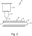
- FIG. 2 is a perspective and partial cross-sectional view of second DED system 30 including conductive heating.
- DED system 30 includes depositor 34, energizing source 36 that provides energized beam 38, and a material (not shown) to be applied using DED system 30, for example.
- DED system 30 also includes tubular base 40 including tubular passageway 43 (one tubular passageway is shown, but base 40 may alternatively include more than one tubular passageway), and heating element 42 that fits within tubular passageway 43 and/or conforms to tubular base 40.
- Tubular base 40 (e.g., stock rod material) and heating element 42 are shown in cross-section in FIG. 2 , with the cross-section being taken along line 2-2 of FIG. 3.
- Heating element 42 contacts inner surface 44 of tubular base 40 and can conductively heat tubular base 40.
- Heating element 42 contacts inner surface 44 of tubular base 40 that is opposite outer surface 46 where material is to be applied or deposited.
- Heating element 42 can be a tubular heating element that fits inside an inner diameter of tubular base 40, as shown.
- heating element 42 can comprise an induction heating, or coiled resistance heating, element that fits inside or around tubular base 40.
- heating element 42 can comprise a plurality of tubular heating elements that can be distributed along inner surface 44 of tubular base 40 (e.g., running along the length of tubular base 40).
- Other exemplary embodiments of heating element 42 of DED system 30 are also contemplated.
- tubular base 40 can rotate with respect to energized beam 38 to adjust the location at which energized beam 38 forms a melt pool (or vice versa, energizing source 36 and/or energized beam 38 can rotate around tubular base 40).
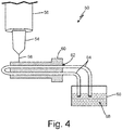
- FIG. 4 is a perspective and partial cross-sectional view of third DED system 50 including conductive heating.
- DED system 50 includes depositor 54, energizing source 56 that provides energized beam 58, and a material (not shown) to be applied using DED system 50, for example.
- Such components of DED system 50 operate generally as understood in the art and as discussed herein with regards to DED system 10 shown in FIG. 1 .
- DED system 50 can be used to conductively heat preexisting component 60 (e.g., a turbine blade) by running heated fluid through pre-existing component 60.
- Pre-existing component 60 is shown in cross-section in FIG. 4 in order to show the presence of vanes 62 or other passageways through which tubing 64 can extend.
- the tubing 64 can be connected to heat-controlled bath 66 in order for heated fluid 68 to be circulated through tubing 64 located within vanes 62 of pre-existing component 60 and conductively heat pre-existing component 60.
- DED system 50 may also include other components that are not shown, such as a pump to move heated fluid 68. DED system 50 can, for example, be used to deposit layers of material to repair pre-existing component 60.
- DED systems 10, 30, 50 described herein can include a control apparatus (not shown) that includes numerous components to control different aspects of the systems.
- a control apparatus may be used to adjust properties of the energized beam, the heating element, melting of an object and deposited material, pumping of heated fluid, etc.
- FIG. 5 is a flow chart of an improved direct energy deposition process 70 using a heating element that can conductively heat a base where deposition takes place using system 10, 30 or 50, for example.
- Process 70 includes multiple steps 72 - 80 to construct an object layer-by-layer to form an object with desirable properties or to repair a pre-existing component.
- Process 70 will also be described with regards to components of DED systems 10, 30 and 50 shown in FIGS. 1-3 , as examples.
- Step 72 is conductively, or otherwise, heating base 12, for example, in DED system 10.
- the heating step can be performed before, after and/or during the other steps 74-80 of process 70. It is contemplated that heat can be supplied to base 12 or a pre-existing component, for example, in various ways. Heat may be conducted to base 12 in DED system 10 by contacting base 12 with heating element 20, which is flat as shown.
- heating element 42 fits within an inner diameter of tubular base (or passageway) 40, and can be tubular in shape, a coiled resistance heating element, or a plurality of tubular heating elements that extend along length of tubular base 40, for example.
- heat can be supplied conductively to pre-existing component 60 via running heated fluid 68 from heat-controlled bath 66 through tubing 64 that extends through passageways 62 that run through pre-existing component 60.
- Other embodiments of conductively heating a base or pre-existing component in the process of DED are also contemplated.
- the conductively heating step can include heating the base to 100 to 200 degrees Celsius greater than ambient temperature prior to a depositing step (step 74, described below).
- the conductively heating step can include heating the base to a temperature such that a difference between the temperature of the base and a melting temperature of the material being applied to the base is reduced to 100 to 200 degrees Celsius.
- Step 74 is depositing a layer of material (i.e., deposited material) used to construct an object or repair a pre-existing component, for example.
- the layer of material is deposited on a base (or a previously deposited portion of an existing component) to form an object layer-by-layer.
- the material can be deposited using depositor 14, and the amount of material deposited at each specified location can vary depending on design considerations and other factors.
- the depositing of material, with various, different configurations and sub-steps, is known to one of skill in the art.
- the temperature or heat level of the base can be monitored to determine or ensure that a desired amount of pre-heating of the base over room temperature is reached prior to depositing material on the base. Such monitoring may be performed by a temperature sensor, for example.
- One or more temperatures sensors can be placed in the system, such as, for example, in contact with the base in order to measure the temperature of the base.
- one or more temperature sensors may be placed in an area surrounding the system in order to measure the temperature of the room (or ambient temperature). Temperatures of the base and the surrounding area, as measured by temperature sensors, for example, may be compared using any suitable method or equipment such that a determination can be made as to whether the base is sufficiently heated in order to then proceed to deposit material on the base.
- step 76 includes providing energy to the layer of the material by an energizing source through the use of an energized beam directed at the deposited material.
- Step 78 includes melting deposited material with an energized beam to form a melted pool of liquified material and a portion of the pre-existing component or object being formed by process 70.
- a most recently deposited material layer may be melted along with a portion of a previously deposited layer forming an object.
- the energy source can be configured to selectively direct an energized beam at the material to fuse a new layer of the material to a previously formed layer.
- step 80 the melted pool (which includes the liquified deposited material and at least a portion of the previously deposited and previously solidified layers of an object or workpiece) is allowed to solidify to bond/fuse the material to the previous layers of the object (or pre-existing component). Then, if necessary, process 70 is performed again to form another layer of an object or pre-existing component, upon the previously deposited layer.
- a system used to additively manufacture an object layer-by-layer using direct energy deposition includes a base where the object is formed, a depositor configured to deposit material layer-by-layer on the base or a previously deposited layer of the object, an energy source configured to selectively direct an energized beam at the material to fuse a new layer of the material to a previously formed layer, and a heating element in contact with at least a portion of the base and configured to supply heat to the base.
- DED direct energy deposition
- the system of the preceding paragraph can optionally include, additionally and/or alternatively, any one or more of the following features, configurations and/or additional components:
- the heating element includes a coiled resistance heating element.
- the heating element includes a plurality of tubular heating elements.
- the base includes a tubular passageway.
- the heating element includes a coiled resistance heating element configured and arranged to fit within the tubular passageway.
- the heating element includes a plurality of tubular heating elements configured and arranged to fit within the tubular passageway and extend along a length of the tubular passageway.
- a temperature of the base is within 100 to 200 degrees Celsius of a melting temperature of the material.
- a temperature of the base is 100 to 200 degrees Celsius above ambient temperature.
- a system used for direct energy deposition of layers of a material to a pre-existing component using DED includes a depositor configured to deposit material layer-by-layer on the pre-existing component or a previously deposited layer of material on the pre-existing component, an energy source configured to selectively direct an energized beam at the material to fuse a new layer of the material to the pre-existing component or to a previously formed layer on the pre-existing component, and a heating element in contact with at least a portion of the pre-existing component and configured to supply heat to the pre-existing component.
- the system of the preceding paragraph can optionally include, additionally and/or alternatively, any one or more of the following features, configurations and/or additional components:
- the heating element includes tubing with heated fluid flowing through the tubing, and a heat-controlled bath apparatus connected to the tubing.
- a temperature of the pre-existing component is 100 to 200 degrees Celsius above ambient temperature.
- a temperature of the pre-exiting component is within 100 to 200 degrees Celsius of a melting temperature of the material.
- a method of depositing layers onto a base using DED includes heating the base, depositing a layer of material on the base or on a previously deposited layer, providing energy to the material after each layer is deposited, the energy being provided by an energy source that forms an energized beam directed at the material, melting the material with the energized beam; and, allowing the material to solidify to bond the material to the base or a previously deposited layer.
- the method of the preceding paragraph can optionally include, additionally and/or alternatively, any one or more of the following features, configurations, steps and/or additional components:
- the heating step is carried out by an induction heating element configured to heat the base.
- the induction heating element includes a coiled resistance heating element configured and arranged to fit within or around the base.
- the heating step is carried out by a plurality of heating elements configured and arranged to fit within and/or extend along a length of the base.
- the heating step includes heating the base to 100 to 200 degrees Celsius greater than ambient temperature prior to the depositing step.
- the heating step includes heating the base to a temperature such that a difference between the temperature of the base and a melting temperature of the material being applied to the base is reduced to 100 to 200 degrees Celsius.
- the energy source is a laser.
- the energy source is an electron beam.
Abstract
Description
- Direct energy deposition (DED) is an additive manufacturing process in which focused thermal energy is used to fuse materials as they are being deposited to produce three-dimensional objects and objects with complex geometries. In DED manufacturing, an industrial laser beam, for example, may be used to form successive layers of material to create or repair objects.
- A system used to additively manufacture an object layer-by-layer using direct energy deposition (DED) includes a base where the object is formed, a depositor configured to deposit material layer-by-layer on the base or a previously deposited layer of the object, an energy source configured to selectively direct an energized beam at the material to fuse a new layer of the material to a previously formed layer, and a heating element in contact with at least a portion of the base and configured to supply heat to the base.
- A method of depositing layers onto a base using DED includes heating the base, depositing a layer of material on the base or on a previously deposited layer, providing energy to the material after each layer is deposited, the energy being provided by an energy source that forms an energized beam directed at the material, melting the material with the energized beam, and allowing the material to solidify to bond the material to the base or a previously deposited layer.
-
-
FIG. 1 is a perspective view of a direct energy deposition (DED) system. -
FIG. 2 is a perspective and partial cross-sectional view of a second DED system. -
FIG. 3 is an end view of a portion of the second DED system shown inFIG. 2 . -
FIG. 4 is a perspective and partial cross-sectional view of a third DED system. -
FIG. 5 is a flow chart of a DED process incorporating in process heating. - An improved system and method of direct energy deposition (DED) used for additively manufacturing (or repairing) a three-dimensional (3D) object, or an object with complex geometry, is disclosed herein. The method includes conductive heating (i.e., secondary heating) of a base (i.e., platform, support surface, work piece, or object) during the formation of successive layers of applied material being applied to the base by DED. Rapid heating and cooling during the DED process can lead to rapid expansion/contraction of the applied material and induce stresses within grain structure and potentially result in cracks or distortion of desired geometry. Heating of the base during application of the applied material can improve weldability and reduce stresses, distortion, and deposition defects during the DED process. A base upon which material may be applied can be heated to a temperature that can be greater than ambient temperature, for example, by about 100 to 200 degrees Celsius. Alternatively, a difference in temperature between a heated base and a melting temperature of material being applied to the base can be reduced to about 100 to 200 degrees Celsius. The heat applied conductively, or otherwise, to the base or pre-existing object during the DED process can be used to better control the additive manufacturing process to provide a finished object that has more desirable properties (e.g., increased strength).
-
FIG. 1 is a perspective view ofDED system 10 including conductive heating.DED system 10 includesbase 12, depositor 14 (e.g., a nozzle), energizingsource 16 that provides energizedbeam 18, and a material (not shown) to be applied usingsystem 10.Heating element 20 contactslower surface 22 ofbase 12 and can conductively heatbase 12. In the embodiment shown,heating element 20 contactslower surface 22 ofbase 12 that is oppositeupper surface 24 where material can be applied or deposited. Other locations ofheating element 20 and other amounts of contact betweenheating element 20 andbase 12 ofsystem 10 are contemplated, however, since heat fromheating element 20 can be conducted a distance throughbase 12.Heating element 20 can supply heat tobase 12 having a temperature that is 100 to 200 degrees Celsius above ambient temperature or room temperature. - "Base," as used in this application, may be an object having a surface on which a bottom, or first, layer of material can be deposited via DED. The base may be a bed of a system, as shown in
DED system 10. Alternatively, base may be a pre-existing component (as shown inFIG. 4 and discussed herein below). - Aside from
heating element 20, most components ofDED system 10 operate generally as understood in the art. Base 12 (which can be flat, ridged, or have another configuration) provides a surface on which an object (not shown) may be formed layer-by-layer or on which a pre-existing component or object may have layers applied thereto during the additive manufacturing process. The material or feedstock forDED system 10 can be a powder or a wire, for example. In laser-based, powder-fed DED, the material being fused is deposited by blowing metallic powder though small nozzles or orifices into a melt pool created by a laser. In laser-based, wire-fed DED, a wire can be fed off-axis and melted by a laser into a melt pool. In both powder- and wire-fed DED, for example, the material can be a metal (such as titanium), an alloy (such as nickel-based alloys), a composite, or another material (such as various steels) able to be used in additive manufacturing. Energizingsource 16 can be any component configured to produce an energizedbeam 18, which can be a laser or an electron beam, for example, to melt the material deposited on an object to form a melt pool.Energized beam 18 is a path between energizingsource 16 and the deposited material along which thermal energy travels. The melt pool is an area of the deposited material and of the object upon which it is deposited that has been liquified by the thermal energy introduced by energizedbeam 18 and, when allowed to melt and solidify, bonds/fuses a layer of deposited material and/or a previously deposited layer to form an object, for example. Energizingsource 16 and/or energizedbeam 18 can be mobile relative to base 12 to adjust the location at which energizedbeam 18 forms a melt pool (or vice versa,base 12 can be mobile relative to energizingsource 16 and/or energized beam 18). An additive manufacturing process using theDED system 10 can alternatively be performed in containment, which can house/contain a gas. Such a gas can be an inert gas (such as argon) as to reduce the reactivity between the gas and the deposited material during a DED process. -
FIG. 2 is a perspective and partial cross-sectional view ofsecond DED system 30 including conductive heating.DED system 30 includesdepositor 34, energizingsource 36 that provides energizedbeam 38, and a material (not shown) to be applied usingDED system 30, for example.DED system 30 also includestubular base 40 including tubular passageway 43 (one tubular passageway is shown, butbase 40 may alternatively include more than one tubular passageway), andheating element 42 that fits withintubular passageway 43 and/or conforms totubular base 40. Tubular base 40 (e.g., stock rod material) andheating element 42 are shown in cross-section inFIG. 2 , with the cross-section being taken along line 2-2 ofFIG. 3. FIG. 3 is an end view oftubular base 40 andheating element 42 together.Heating element 42 contactsinner surface 44 oftubular base 40 and can conductively heattubular base 40. In the embodiment shown inFIGS. 2 and3 ,heating element 42 contactsinner surface 44 oftubular base 40 that is oppositeouter surface 46 where material is to be applied or deposited.Heating element 42 can be a tubular heating element that fits inside an inner diameter oftubular base 40, as shown. Alternatively,heating element 42 can comprise an induction heating, or coiled resistance heating, element that fits inside or aroundtubular base 40. In another alternative,heating element 42 can comprise a plurality of tubular heating elements that can be distributed alonginner surface 44 of tubular base 40 (e.g., running along the length of tubular base 40). Other exemplary embodiments ofheating element 42 ofDED system 30 are also contemplated. - Aside from
heating element 42, most components ofDED system 30 operate generally as understood in the art and as discussed herein with regards toDED system 10 shown inFIG. 1 . Additionally,tubular base 40 can rotate with respect to energizedbeam 38 to adjust the location at which energizedbeam 38 forms a melt pool (or vice versa, energizingsource 36 and/or energizedbeam 38 can rotate around tubular base 40). -
FIG. 4 is a perspective and partial cross-sectional view ofthird DED system 50 including conductive heating.DED system 50 includesdepositor 54, energizingsource 56 that provides energizedbeam 58, and a material (not shown) to be applied usingDED system 50, for example. Such components ofDED system 50 operate generally as understood in the art and as discussed herein with regards toDED system 10 shown inFIG. 1 .DED system 50 can be used to conductively heat preexisting component 60 (e.g., a turbine blade) by running heated fluid throughpre-existing component 60.Pre-existing component 60 is shown in cross-section inFIG. 4 in order to show the presence ofvanes 62 or other passageways through whichtubing 64 can extend. Thetubing 64 can be connected to heat-controlledbath 66 in order forheated fluid 68 to be circulated throughtubing 64 located withinvanes 62 ofpre-existing component 60 and conductively heatpre-existing component 60.DED system 50 may also include other components that are not shown, such as a pump to moveheated fluid 68.DED system 50 can, for example, be used to deposit layers of material to repairpre-existing component 60. -
DED systems -
FIG. 5 is a flow chart of an improved directenergy deposition process 70 using a heating element that can conductively heat a base where deposition takesplace using system Process 70 includes multiple steps 72 - 80 to construct an object layer-by-layer to form an object with desirable properties or to repair a pre-existing component.Process 70 will also be described with regards to components ofDED systems FIGS. 1-3 , as examples. -
Step 72 is conductively, or otherwise,heating base 12, for example, inDED system 10. The heating step can be performed before, after and/or during the other steps 74-80 ofprocess 70. It is contemplated that heat can be supplied tobase 12 or a pre-existing component, for example, in various ways. Heat may be conducted tobase 12 inDED system 10 by contactingbase 12 withheating element 20, which is flat as shown. InDED system 30,heating element 42 fits within an inner diameter of tubular base (or passageway) 40, and can be tubular in shape, a coiled resistance heating element, or a plurality of tubular heating elements that extend along length oftubular base 40, for example. InDED system 50, heat can be supplied conductively topre-existing component 60 via running heated fluid 68 from heat-controlledbath 66 throughtubing 64 that extends throughpassageways 62 that run throughpre-existing component 60. Other embodiments of conductively heating a base or pre-existing component in the process of DED are also contemplated. - In an embodiment, the conductively heating step can include heating the base to 100 to 200 degrees Celsius greater than ambient temperature prior to a depositing step (step 74, described below). Alternatively and/or additionally, the conductively heating step can include heating the base to a temperature such that a difference between the temperature of the base and a melting temperature of the material being applied to the base is reduced to 100 to 200 degrees Celsius.
- Step 74 is depositing a layer of material (i.e., deposited material) used to construct an object or repair a pre-existing component, for example. The layer of material is deposited on a base (or a previously deposited portion of an existing component) to form an object layer-by-layer. The material can be deposited using
depositor 14, and the amount of material deposited at each specified location can vary depending on design considerations and other factors. The depositing of material, with various, different configurations and sub-steps, is known to one of skill in the art. The temperature or heat level of the base can be monitored to determine or ensure that a desired amount of pre-heating of the base over room temperature is reached prior to depositing material on the base. Such monitoring may be performed by a temperature sensor, for example. One or more temperatures sensors can be placed in the system, such as, for example, in contact with the base in order to measure the temperature of the base. In addition, one or more temperature sensors may be placed in an area surrounding the system in order to measure the temperature of the room (or ambient temperature). Temperatures of the base and the surrounding area, as measured by temperature sensors, for example, may be compared using any suitable method or equipment such that a determination can be made as to whether the base is sufficiently heated in order to then proceed to deposit material on the base. After each layer of material is deposited,step 76 includes providing energy to the layer of the material by an energizing source through the use of an energized beam directed at the deposited material. -
Step 78 includes melting deposited material with an energized beam to form a melted pool of liquified material and a portion of the pre-existing component or object being formed byprocess 70. A most recently deposited material layer may be melted along with a portion of a previously deposited layer forming an object. The energy source can be configured to selectively direct an energized beam at the material to fuse a new layer of the material to a previously formed layer. - Finally, in
step 80, the melted pool (which includes the liquified deposited material and at least a portion of the previously deposited and previously solidified layers of an object or workpiece) is allowed to solidify to bond/fuse the material to the previous layers of the object (or pre-existing component). Then, if necessary,process 70 is performed again to form another layer of an object or pre-existing component, upon the previously deposited layer. - The following are non-exclusive descriptions of possible embodiments of the present invention.
- A system used to additively manufacture an object layer-by-layer using direct energy deposition (DED) includes a base where the object is formed, a depositor configured to deposit material layer-by-layer on the base or a previously deposited layer of the object, an energy source configured to selectively direct an energized beam at the material to fuse a new layer of the material to a previously formed layer, and a heating element in contact with at least a portion of the base and configured to supply heat to the base.
- The system of the preceding paragraph can optionally include, additionally and/or alternatively, any one or more of the following features, configurations and/or additional components:
The heating element includes a coiled resistance heating element. - The heating element includes a plurality of tubular heating elements.
- The base includes a tubular passageway.
- The heating element includes a coiled resistance heating element configured and arranged to fit within the tubular passageway.
- The heating element includes a plurality of tubular heating elements configured and arranged to fit within the tubular passageway and extend along a length of the tubular passageway.
- A temperature of the base is within 100 to 200 degrees Celsius of a melting temperature of the material.
- A temperature of the base is 100 to 200 degrees Celsius above ambient temperature.
- A system used for direct energy deposition of layers of a material to a pre-existing component using DED includes a depositor configured to deposit material layer-by-layer on the pre-existing component or a previously deposited layer of material on the pre-existing component, an energy source configured to selectively direct an energized beam at the material to fuse a new layer of the material to the pre-existing component or to a previously formed layer on the pre-existing component, and a heating element in contact with at least a portion of the pre-existing component and configured to supply heat to the pre-existing component.
- The system of the preceding paragraph can optionally include, additionally and/or alternatively, any one or more of the following features, configurations and/or additional components:
The heating element includes tubing with heated fluid flowing through the tubing, and a heat-controlled bath apparatus connected to the tubing. - A temperature of the pre-existing component is 100 to 200 degrees Celsius above ambient temperature.
- A temperature of the pre-exiting component is within 100 to 200 degrees Celsius of a melting temperature of the material.
- A method of depositing layers onto a base using DED includes heating the base, depositing a layer of material on the base or on a previously deposited layer, providing energy to the material after each layer is deposited, the energy being provided by an energy source that forms an energized beam directed at the material, melting the material with the energized beam; and, allowing the material to solidify to bond the material to the base or a previously deposited layer.
- The method of the preceding paragraph can optionally include, additionally and/or alternatively, any one or more of the following features, configurations, steps and/or additional components:
The heating step is carried out by an induction heating element configured to heat the base. - The induction heating element includes a coiled resistance heating element configured and arranged to fit within or around the base.
- The heating step is carried out by a plurality of heating elements configured and arranged to fit within and/or extend along a length of the base.
- The heating step includes heating the base to 100 to 200 degrees Celsius greater than ambient temperature prior to the depositing step.
- The heating step includes heating the base to a temperature such that a difference between the temperature of the base and a melting temperature of the material being applied to the base is reduced to 100 to 200 degrees Celsius.
- The energy source is a laser.
- The energy source is an electron beam.
- Monitoring heat of the base to determine a temperature of the base prior to the depositing step.
- While the invention has been described with reference to an exemplary embodiment(s), it will be understood by those skilled in the art that various changes may be made without departing from the scope of the invention as defined by the claims. In addition, many modifications may be made to adapt a particular situation or material to the teachings of the invention without departing from the scope of the claims. Therefore, it is intended that the invention not be limited to the particular embodiment(s) disclosed, but that the invention will include all embodiments falling within the scope of the appended claims.
Claims (15)
- A system used to additively manufacture an object layer-by-layer using direct energy deposition, DED, the system comprising:a base (12) where the object is formed;a depositor (14) configured to deposit material layer-by-layer on the base or a previously deposited layer of the object;an energy source (16) configured to selectively direct an energized beam at the material to fuse a new layer of the material to a previously formed layer; anda heating element (20) in contact with at least a portion of the base and configured to supply heat to the base.
- The system of claim 1, wherein the heating element comprises an induction heating element, or wherein the heating element comprises a plurality of tubular heating elements.
- The system of claim 1 or 2, wherein the base includes a tubular passageway (43).
- The system of claim 3, wherein the heating element comprises an induction heating element configured and arranged to fit within the tubular passageway, or wherein the heating element comprises a plurality of tubular heating elements configured and arranged to fit within the tubular passageway and extend along a length of the tubular passageway.
- The system of any preceding claim, wherein a temperature of the base is 100 to 200 degrees Celsius above ambient temperature, or wherein a temperature of the base is within 100 to 200 degrees Celsius of a melting temperature of the material.
- A system used for direct energy deposition of layers of a material to a pre-existing component using direct energy deposition, DED, the system comprising:a depositor (14) configured to deposit material layer-by-layer on the pre-existing component or a previously deposited layer of material on the pre-existing component;an energy source (16) configured to selectively direct an energized beam at the material to fuse a new layer of the material to the pre-existing component or to a previously formed layer on the pre-existing component; anda heating element (20) in contact with at least a portion of the pre-existing component and configured to supply heat to the pre-existing component.
- The system of claim 6, wherein the heating element includes tubing with heated fluid flowing through the tubing, and a heat-controlled bath apparatus connected to the tubing.
- The system of claim 6 or 7, wherein a temperature of the pre-existing component is 100 to 200 degrees Celsius above ambient temperature, or wherein a temperature of the pre-exiting component is within 100 to 200 degrees Celsius of a melting temperature of the material.
- A method of depositing layers onto a base using direct energy deposition, DED, the method comprising:heating the base (12);depositing a layer of material on the base or on a previously deposited layer;providing energy to the material after each layer is deposited, the energy being provided by an energy source (16) that forms an energized beam directed at the material;melting the material; andallowing the material to solidify to bond the material to the base or the previously deposited layer.
- The method of claim 9, wherein the heating step is carried out by an induction heating element configured to heat the base.
- The method of claim 10, wherein the induction heating element includes a coiled resistance heating element configured and arranged to fit within or around the base.
- The method of claim 9, wherein the heating step is carried out by a plurality of heating elements configured and arranged to fit within and/or extend along a length of the base.
- The method of any of claims 9 to 12, wherein the heating step includes heating the base to 100 to 200 degrees Celsius greater than ambient temperature prior to the depositing step, or wherein the heating step includes heating the base to a temperature such that a difference between the temperature of the base and a melting temperature of the material being applied to the base is reduced to 100 to 200 degrees Celsius.
- The method of any of claims 9 to 13, wherein the energy source is selected from a group consisting of a laser and an electron beam.
- The method of any of claims 9 to 14, further comprising:
monitoring heat of the base to determine a temperature of the base prior to the depositing step.
Applications Claiming Priority (1)
| Application Number | Priority Date | Filing Date | Title |
|---|---|---|---|
| US16/827,159 US11396063B2 (en) | 2020-03-23 | 2020-03-23 | Systems and methods for in process heating for direct energy deposition applications |
Publications (2)
| Publication Number | Publication Date |
|---|---|
| EP3885065A1 true EP3885065A1 (en) | 2021-09-29 |
| EP3885065B1 EP3885065B1 (en) | 2023-05-03 |
Family
ID=75362323
Family Applications (1)
| Application Number | Title | Priority Date | Filing Date |
|---|---|---|---|
| EP21164414.1A Active EP3885065B1 (en) | 2020-03-23 | 2021-03-23 | Systems and methods for in process heating for direct energy deposition applications |
Country Status (2)
| Country | Link |
|---|---|
| US (1) | US11396063B2 (en) |
| EP (1) | EP3885065B1 (en) |
Citations (5)
| Publication number | Priority date | Publication date | Assignee | Title |
|---|---|---|---|---|
| EP2377669A1 (en) * | 2010-04-14 | 2011-10-19 | Matsuura Machinery Corporation | Apparatus for producing three-dimensional shaped product |
| CN103624259A (en) * | 2013-12-06 | 2014-03-12 | 沈阳航空航天大学 | Metal part laser deposition repairing method and device based on regulation of preset gradient temperature field |
| CN107756798A (en) * | 2017-12-04 | 2018-03-06 | 深圳森工科技有限公司 | The heating module and its heating means of 3D printer |
| US20180133958A1 (en) * | 2016-03-25 | 2018-05-17 | Technology Research Association For Future Additive Manufacturing | Three-dimensional laminating and shaping apparatus, control method of three-dimensional laminating and shaping apparatus, control program of three-dimensional laminating and shaping apparatus, and jig |
| WO2019177607A1 (en) * | 2018-03-15 | 2019-09-19 | Siemens Energy, Inc. | Laser braze wire additive manufacturing of a super solutioned turbine blade component with subzero cooling |
Family Cites Families (15)
| Publication number | Priority date | Publication date | Assignee | Title |
|---|---|---|---|---|
| EP2415552A1 (en) | 2010-08-05 | 2012-02-08 | Siemens Aktiengesellschaft | A method for manufacturing a component by selective laser melting |
| US9399257B2 (en) * | 2014-04-16 | 2016-07-26 | Honeywell International Inc. | Methods for forming ceramic reinforced titanium alloys |
| JP6219228B2 (en) * | 2014-05-12 | 2017-10-25 | 光洋サーモシステム株式会社 | Induction heating coil and method of manufacturing induction heating coil |
| KR102383340B1 (en) * | 2014-07-21 | 2022-04-07 | 누보 피그노네 에스알엘 | Method for manufacturing machine components by additive manufacturing |
| FR3034691A1 (en) * | 2015-04-07 | 2016-10-14 | Soc Eder | THREE-DIMENSIONAL PRINTING DEVICE USING INDUCTIVE AND RESISTIVE DEVICES |
| WO2017004042A1 (en) | 2015-06-29 | 2017-01-05 | Applied Materials, Inc. | Temperature controlled additive manufacturing |
| JP6570346B2 (en) * | 2015-07-07 | 2019-09-04 | 日立オートモティブシステムズ株式会社 | Hollow composite magnetic member, method for manufacturing the same, and fuel injection valve |
| US10443115B2 (en) * | 2015-08-20 | 2019-10-15 | General Electric Company | Apparatus and method for direct writing of single crystal super alloys and metals |
| US20180169938A1 (en) | 2015-11-13 | 2018-06-21 | Technology Research Association For Future Additive Manufacturing | Three-dimensional laminating and shaping apparatus, method of manufacturing three-dimensional laminating and shaping apparatus, and program for manufacturing three-dimensional laminating and shaping apparatus |
| EP3448663A1 (en) | 2016-04-27 | 2019-03-06 | SABIC Global Technologies B.V. | 3d printer with independent multi zone temperature controller |
| CN110650811B (en) * | 2017-08-08 | 2021-08-31 | 三菱重工业株式会社 | Internal defect detection system and method, and three-dimensional laminated modeling device |
| US20190118252A1 (en) * | 2017-10-20 | 2019-04-25 | Desktop Metal, Inc. | Induction heating systems and techniques for fused filament metal fabrication |
| DE102017222162A1 (en) * | 2017-12-07 | 2019-06-13 | Robert Bosch Gmbh | Apparatus for the additive production of three-dimensional workpieces and method for operating a device for the additive production of three-dimensional workpieces |
| JP2019142024A (en) | 2018-02-16 | 2019-08-29 | 株式会社日立製作所 | Additive manufacturing apparatus |
| US20210060922A1 (en) * | 2019-08-27 | 2021-03-04 | Delavan Inc. | Temperature control for additive manufacturing |
-
2020
- 2020-03-23 US US16/827,159 patent/US11396063B2/en active Active
-
2021
- 2021-03-23 EP EP21164414.1A patent/EP3885065B1/en active Active
Patent Citations (5)
| Publication number | Priority date | Publication date | Assignee | Title |
|---|---|---|---|---|
| EP2377669A1 (en) * | 2010-04-14 | 2011-10-19 | Matsuura Machinery Corporation | Apparatus for producing three-dimensional shaped product |
| CN103624259A (en) * | 2013-12-06 | 2014-03-12 | 沈阳航空航天大学 | Metal part laser deposition repairing method and device based on regulation of preset gradient temperature field |
| US20180133958A1 (en) * | 2016-03-25 | 2018-05-17 | Technology Research Association For Future Additive Manufacturing | Three-dimensional laminating and shaping apparatus, control method of three-dimensional laminating and shaping apparatus, control program of three-dimensional laminating and shaping apparatus, and jig |
| CN107756798A (en) * | 2017-12-04 | 2018-03-06 | 深圳森工科技有限公司 | The heating module and its heating means of 3D printer |
| WO2019177607A1 (en) * | 2018-03-15 | 2019-09-19 | Siemens Energy, Inc. | Laser braze wire additive manufacturing of a super solutioned turbine blade component with subzero cooling |
Non-Patent Citations (1)
| Title |
|---|
| SHIM DO-SIK ET AL: "Effect of substrate preheating by induction heater on direct energy deposition of AISI M4 powder", MATERIALS SCIENCE AND ENGINEERING: A, vol. 682, 12 November 2016 (2016-11-12), AMSTERDAM, NL, pages 550 - 562, XP055821863, ISSN: 0921-5093, DOI: 10.1016/j.msea.2016.11.029 * |
Also Published As
| Publication number | Publication date |
|---|---|
| EP3885065B1 (en) | 2023-05-03 |
| US11396063B2 (en) | 2022-07-26 |
| US20210291299A1 (en) | 2021-09-23 |
Similar Documents
| Publication | Publication Date | Title |
|---|---|---|
| EP1584398B1 (en) | Two tier brazing process for joining copper tubes to a fitting | |
| EP3115132B1 (en) | Additive manufacturing of joining preforms | |
| EP3551594B1 (en) | Method to additively manufacture a fiber-reinforced ceramic matrix composite | |
| US6998568B2 (en) | Method for fabricating, modifying or repairing of single crystal or directionally solidified articles | |
| US20060231535A1 (en) | Method of welding a gamma-prime precipitate strengthened material | |
| US20030068518A1 (en) | Process of forming a composite coating on a substrate | |
| EP3768453B1 (en) | Method and system for additive manufacturing or repair with in-situ manufacturing and feeding of a sintered wire | |
| WO2004022816A1 (en) | Method for controlling the microstructure of a laser metal formed hard layer | |
| JP2008501527A (en) | Method for joining parts to be joined by brazing or welding and apparatus for performing the joining method | |
| EP3459673B1 (en) | Additive manufacturing in situ stress relief | |
| US6443352B1 (en) | Electrical resistance based object consolidation | |
| Zhang et al. | Additive manufacturing of cobalt-based alloy on tool steel by directed energy deposition | |
| EP3885065A1 (en) | Systems and methods for in process heating for direct energy deposition applications | |
| Nikam et al. | 3D-finite element simulation and image processing based prediction of width and height of single-layer deposition by micro-plasma-transferred arc process | |
| EP3766604A1 (en) | Method and device for purging an additive manufacturing space | |
| JP7041042B2 (en) | Method of laminating the hardened layer and method of manufacturing the laminated model | |
| Chua et al. | Influences of deposition strategies on thermo-mechanical characteristics of a multilayer part deposited by a wire feeding type DED process | |
| Durandet et al. | Challenges of laser cladding Al 7075 alloy with AI-12Si Alloy powder | |
| EP2656962A2 (en) | Remote melt joining methods and remote melt joining systems | |
| Davis et al. | Optimum deposition parameters for the direct laser fabrication (DLF) of quasi-hollow structures | |
| EP4166260A1 (en) | An additive manufacturing process comprising directed-energy deposition and pre-depositing interface metal layers | |
| Felipe Ribeiro et al. | Combined effect of the interlayer temperature with travel speed on features of thin wall WAAM under two cooling approaches | |
| EP3304663B1 (en) | A method of forming a metal electrode on the ceramic insulator of a spark plug | |
| JP2790849B2 (en) | Repair method of weld bead cutting part of galvanized ERW pipe | |
| JPS63227758A (en) | Method for coating base material with metallized layer and obtained product |
Legal Events
| Date | Code | Title | Description |
|---|---|---|---|
| PUAI | Public reference made under article 153(3) epc to a published international application that has entered the european phase |
Free format text: ORIGINAL CODE: 0009012 |
|
| STAA | Information on the status of an ep patent application or granted ep patent |
Free format text: STATUS: THE APPLICATION HAS BEEN PUBLISHED |
|
| AK | Designated contracting states |
Kind code of ref document: A1 Designated state(s): AL AT BE BG CH CY CZ DE DK EE ES FI FR GB GR HR HU IE IS IT LI LT LU LV MC MK MT NL NO PL PT RO RS SE SI SK SM TR |
|
| STAA | Information on the status of an ep patent application or granted ep patent |
Free format text: STATUS: REQUEST FOR EXAMINATION WAS MADE |
|
| 17P | Request for examination filed |
Effective date: 20220329 |
|
| RBV | Designated contracting states (corrected) |
Designated state(s): AL AT BE BG CH CY CZ DE DK EE ES FI FR GB GR HR HU IE IS IT LI LT LU LV MC MK MT NL NO PL PT RO RS SE SI SK SM TR |
|
| REG | Reference to a national code |
Ref country code: DE Ref document number: 602021002123 Country of ref document: DE Free format text: PREVIOUS MAIN CLASS: B22F0010200000 Ref legal event code: R079 Ipc: B22F0010250000 |
|
| GRAP | Despatch of communication of intention to grant a patent |
Free format text: ORIGINAL CODE: EPIDOSNIGR1 |
|
| STAA | Information on the status of an ep patent application or granted ep patent |
Free format text: STATUS: GRANT OF PATENT IS INTENDED |
|
| RIC1 | Information provided on ipc code assigned before grant |
Ipc: B23K 26/70 20140101ALI20230125BHEP Ipc: B23K 15/00 20060101ALI20230125BHEP Ipc: B22F 7/08 20060101ALI20230125BHEP Ipc: B22F 7/06 20060101ALI20230125BHEP Ipc: B33Y 30/00 20150101ALI20230125BHEP Ipc: B33Y 10/00 20150101ALI20230125BHEP Ipc: B23K 26/342 20140101ALI20230125BHEP Ipc: B22F 12/30 20210101ALI20230125BHEP Ipc: B22F 12/17 20210101ALI20230125BHEP Ipc: B22F 10/25 20210101AFI20230125BHEP |
|
| INTG | Intention to grant announced |
Effective date: 20230213 |
|
| GRAS | Grant fee paid |
Free format text: ORIGINAL CODE: EPIDOSNIGR3 |
|
| GRAA | (expected) grant |
Free format text: ORIGINAL CODE: 0009210 |
|
| STAA | Information on the status of an ep patent application or granted ep patent |
Free format text: STATUS: THE PATENT HAS BEEN GRANTED |
|
| RIN1 | Information on inventor provided before grant (corrected) |
Inventor name: CHOU, RYAN PHILIP Inventor name: JOHNSON, PAUL ROBERT Inventor name: WIGAN, SCOTT Inventor name: PITERA, RUDY |
|
| AK | Designated contracting states |
Kind code of ref document: B1 Designated state(s): AL AT BE BG CH CY CZ DE DK EE ES FI FR GB GR HR HU IE IS IT LI LT LU LV MC MK MT NL NO PL PT RO RS SE SI SK SM TR |
|
| REG | Reference to a national code |
Ref country code: GB Ref legal event code: FG4D |
|
| REG | Reference to a national code |
Ref country code: DE Ref legal event code: R096 Ref document number: 602021002123 Country of ref document: DE |
|
| REG | Reference to a national code |
Ref country code: AT Ref legal event code: REF Ref document number: 1564148 Country of ref document: AT Kind code of ref document: T Effective date: 20230515 Ref country code: CH Ref legal event code: EP |
|
| REG | Reference to a national code |
Ref country code: IE Ref legal event code: FG4D |
|
| REG | Reference to a national code |
Ref country code: LT Ref legal event code: MG9D |
|
| REG | Reference to a national code |
Ref country code: NL Ref legal event code: MP Effective date: 20230503 |
|
| REG | Reference to a national code |
Ref country code: AT Ref legal event code: MK05 Ref document number: 1564148 Country of ref document: AT Kind code of ref document: T Effective date: 20230503 |
|
| PG25 | Lapsed in a contracting state [announced via postgrant information from national office to epo] |
Ref country code: SE Free format text: LAPSE BECAUSE OF FAILURE TO SUBMIT A TRANSLATION OF THE DESCRIPTION OR TO PAY THE FEE WITHIN THE PRESCRIBED TIME-LIMIT Effective date: 20230503 Ref country code: PT Free format text: LAPSE BECAUSE OF FAILURE TO SUBMIT A TRANSLATION OF THE DESCRIPTION OR TO PAY THE FEE WITHIN THE PRESCRIBED TIME-LIMIT Effective date: 20230904 Ref country code: NO Free format text: LAPSE BECAUSE OF FAILURE TO SUBMIT A TRANSLATION OF THE DESCRIPTION OR TO PAY THE FEE WITHIN THE PRESCRIBED TIME-LIMIT Effective date: 20230803 Ref country code: NL Free format text: LAPSE BECAUSE OF FAILURE TO SUBMIT A TRANSLATION OF THE DESCRIPTION OR TO PAY THE FEE WITHIN THE PRESCRIBED TIME-LIMIT Effective date: 20230503 Ref country code: ES Free format text: LAPSE BECAUSE OF FAILURE TO SUBMIT A TRANSLATION OF THE DESCRIPTION OR TO PAY THE FEE WITHIN THE PRESCRIBED TIME-LIMIT Effective date: 20230503 Ref country code: AT Free format text: LAPSE BECAUSE OF FAILURE TO SUBMIT A TRANSLATION OF THE DESCRIPTION OR TO PAY THE FEE WITHIN THE PRESCRIBED TIME-LIMIT Effective date: 20230503 |
|
| PG25 | Lapsed in a contracting state [announced via postgrant information from national office to epo] |
Ref country code: RS Free format text: LAPSE BECAUSE OF FAILURE TO SUBMIT A TRANSLATION OF THE DESCRIPTION OR TO PAY THE FEE WITHIN THE PRESCRIBED TIME-LIMIT Effective date: 20230503 Ref country code: PL Free format text: LAPSE BECAUSE OF FAILURE TO SUBMIT A TRANSLATION OF THE DESCRIPTION OR TO PAY THE FEE WITHIN THE PRESCRIBED TIME-LIMIT Effective date: 20230503 Ref country code: LV Free format text: LAPSE BECAUSE OF FAILURE TO SUBMIT A TRANSLATION OF THE DESCRIPTION OR TO PAY THE FEE WITHIN THE PRESCRIBED TIME-LIMIT Effective date: 20230503 Ref country code: LT Free format text: LAPSE BECAUSE OF FAILURE TO SUBMIT A TRANSLATION OF THE DESCRIPTION OR TO PAY THE FEE WITHIN THE PRESCRIBED TIME-LIMIT Effective date: 20230503 Ref country code: IS Free format text: LAPSE BECAUSE OF FAILURE TO SUBMIT A TRANSLATION OF THE DESCRIPTION OR TO PAY THE FEE WITHIN THE PRESCRIBED TIME-LIMIT Effective date: 20230903 Ref country code: HR Free format text: LAPSE BECAUSE OF FAILURE TO SUBMIT A TRANSLATION OF THE DESCRIPTION OR TO PAY THE FEE WITHIN THE PRESCRIBED TIME-LIMIT Effective date: 20230503 Ref country code: GR Free format text: LAPSE BECAUSE OF FAILURE TO SUBMIT A TRANSLATION OF THE DESCRIPTION OR TO PAY THE FEE WITHIN THE PRESCRIBED TIME-LIMIT Effective date: 20230804 |
|
| PG25 | Lapsed in a contracting state [announced via postgrant information from national office to epo] |
Ref country code: FI Free format text: LAPSE BECAUSE OF FAILURE TO SUBMIT A TRANSLATION OF THE DESCRIPTION OR TO PAY THE FEE WITHIN THE PRESCRIBED TIME-LIMIT Effective date: 20230503 |
|
| PG25 | Lapsed in a contracting state [announced via postgrant information from national office to epo] |
Ref country code: SK Free format text: LAPSE BECAUSE OF FAILURE TO SUBMIT A TRANSLATION OF THE DESCRIPTION OR TO PAY THE FEE WITHIN THE PRESCRIBED TIME-LIMIT Effective date: 20230503 |
|
| PG25 | Lapsed in a contracting state [announced via postgrant information from national office to epo] |
Ref country code: SM Free format text: LAPSE BECAUSE OF FAILURE TO SUBMIT A TRANSLATION OF THE DESCRIPTION OR TO PAY THE FEE WITHIN THE PRESCRIBED TIME-LIMIT Effective date: 20230503 Ref country code: SK Free format text: LAPSE BECAUSE OF FAILURE TO SUBMIT A TRANSLATION OF THE DESCRIPTION OR TO PAY THE FEE WITHIN THE PRESCRIBED TIME-LIMIT Effective date: 20230503 Ref country code: RO Free format text: LAPSE BECAUSE OF FAILURE TO SUBMIT A TRANSLATION OF THE DESCRIPTION OR TO PAY THE FEE WITHIN THE PRESCRIBED TIME-LIMIT Effective date: 20230503 Ref country code: EE Free format text: LAPSE BECAUSE OF FAILURE TO SUBMIT A TRANSLATION OF THE DESCRIPTION OR TO PAY THE FEE WITHIN THE PRESCRIBED TIME-LIMIT Effective date: 20230503 Ref country code: DK Free format text: LAPSE BECAUSE OF FAILURE TO SUBMIT A TRANSLATION OF THE DESCRIPTION OR TO PAY THE FEE WITHIN THE PRESCRIBED TIME-LIMIT Effective date: 20230503 Ref country code: CZ Free format text: LAPSE BECAUSE OF FAILURE TO SUBMIT A TRANSLATION OF THE DESCRIPTION OR TO PAY THE FEE WITHIN THE PRESCRIBED TIME-LIMIT Effective date: 20230503 |
|
| REG | Reference to a national code |
Ref country code: DE Ref legal event code: R097 Ref document number: 602021002123 Country of ref document: DE |
|
| PLBE | No opposition filed within time limit |
Free format text: ORIGINAL CODE: 0009261 |
|
| STAA | Information on the status of an ep patent application or granted ep patent |
Free format text: STATUS: NO OPPOSITION FILED WITHIN TIME LIMIT |
|
| 26N | No opposition filed |
Effective date: 20240206 |