EP3884828B1 - Materialverriegelungssysteme für walzgutspender - Google Patents
Materialverriegelungssysteme für walzgutspender Download PDFInfo
- Publication number
- EP3884828B1 EP3884828B1 EP20217080.9A EP20217080A EP3884828B1 EP 3884828 B1 EP3884828 B1 EP 3884828B1 EP 20217080 A EP20217080 A EP 20217080A EP 3884828 B1 EP3884828 B1 EP 3884828B1
- Authority
- EP
- European Patent Office
- Prior art keywords
- insert
- hub
- web material
- roll
- dispenser
- Prior art date
- Legal status (The legal status is an assumption and is not a legal conclusion. Google has not performed a legal analysis and makes no representation as to the accuracy of the status listed.)
- Active
Links
Images



Classifications
-
- A—HUMAN NECESSITIES
- A47—FURNITURE; DOMESTIC ARTICLES OR APPLIANCES; COFFEE MILLS; SPICE MILLS; SUCTION CLEANERS IN GENERAL
- A47K—SANITARY EQUIPMENT; ACCESSORIES THEREFOR, e.g. TOILET ACCESSORIES
- A47K10/00—Body-drying implements; Toilet paper; Holders therefor
- A47K10/16—Paper towels; Toilet paper; Holders therefor
-
- A—HUMAN NECESSITIES
- A47—FURNITURE; DOMESTIC ARTICLES OR APPLIANCES; COFFEE MILLS; SPICE MILLS; SUCTION CLEANERS IN GENERAL
- A47K—SANITARY EQUIPMENT; ACCESSORIES THEREFOR, e.g. TOILET ACCESSORIES
- A47K10/00—Body-drying implements; Toilet paper; Holders therefor
- A47K10/24—Towel dispensers; Toilet paper dispensers
- A47K10/32—Dispensers for paper towels or toilet paper
- A47K10/34—Dispensers for paper towels or toilet paper dispensing from a web, e.g. with mechanical dispensing means
- A47K10/38—Dispensers for paper towels or toilet paper dispensing from a web, e.g. with mechanical dispensing means the web being rolled-up
- A47K10/3845—Dispensers for paper towels or toilet paper dispensing from a web, e.g. with mechanical dispensing means the web being rolled-up with devices preventing the use of non-authorised paper rolls
-
- B—PERFORMING OPERATIONS; TRANSPORTING
- B65—CONVEYING; PACKING; STORING; HANDLING THIN OR FILAMENTARY MATERIAL
- B65H—HANDLING THIN OR FILAMENTARY MATERIAL, e.g. SHEETS, WEBS, CABLES
- B65H16/00—Unwinding, paying-out webs
- B65H16/005—Dispensers, i.e. machines for unwinding only parts of web roll
-
- B—PERFORMING OPERATIONS; TRANSPORTING
- B65—CONVEYING; PACKING; STORING; HANDLING THIN OR FILAMENTARY MATERIAL
- B65H—HANDLING THIN OR FILAMENTARY MATERIAL, e.g. SHEETS, WEBS, CABLES
- B65H75/00—Storing webs, tapes, or filamentary material, e.g. on reels
- B65H75/02—Cores, formers, supports, or holders for coiled, wound, or folded material, e.g. reels, spindles, bobbins, cop tubes, cans, mandrels or chucks
- B65H75/18—Constructional details
- B65H75/185—End caps, plugs or adapters
-
- A—HUMAN NECESSITIES
- A47—FURNITURE; DOMESTIC ARTICLES OR APPLIANCES; COFFEE MILLS; SPICE MILLS; SUCTION CLEANERS IN GENERAL
- A47K—SANITARY EQUIPMENT; ACCESSORIES THEREFOR, e.g. TOILET ACCESSORIES
- A47K10/00—Body-drying implements; Toilet paper; Holders therefor
- A47K10/24—Towel dispensers; Toilet paper dispensers
- A47K10/32—Dispensers for paper towels or toilet paper
- A47K10/34—Dispensers for paper towels or toilet paper dispensing from a web, e.g. with mechanical dispensing means
- A47K10/38—Dispensers for paper towels or toilet paper dispensing from a web, e.g. with mechanical dispensing means the web being rolled-up
-
- B—PERFORMING OPERATIONS; TRANSPORTING
- B65—CONVEYING; PACKING; STORING; HANDLING THIN OR FILAMENTARY MATERIAL
- B65H—HANDLING THIN OR FILAMENTARY MATERIAL, e.g. SHEETS, WEBS, CABLES
- B65H2301/00—Handling processes for sheets or webs
- B65H2301/40—Type of handling process
- B65H2301/41—Winding, unwinding
- B65H2301/413—Supporting web roll
- B65H2301/4134—Both ends type arrangement
- B65H2301/41346—Both ends type arrangement separate elements engaging each end of the roll (e.g. chuck)
-
- B—PERFORMING OPERATIONS; TRANSPORTING
- B65—CONVEYING; PACKING; STORING; HANDLING THIN OR FILAMENTARY MATERIAL
- B65H—HANDLING THIN OR FILAMENTARY MATERIAL, e.g. SHEETS, WEBS, CABLES
- B65H2301/00—Handling processes for sheets or webs
- B65H2301/40—Type of handling process
- B65H2301/41—Winding, unwinding
- B65H2301/413—Supporting web roll
- B65H2301/4136—Mounting arrangements not otherwise provided for
- B65H2301/41369—Mounting arrangements not otherwise provided for hub arrangements, i.e. involving additional part between core / roll and machine bearing
-
- B—PERFORMING OPERATIONS; TRANSPORTING
- B65—CONVEYING; PACKING; STORING; HANDLING THIN OR FILAMENTARY MATERIAL
- B65H—HANDLING THIN OR FILAMENTARY MATERIAL, e.g. SHEETS, WEBS, CABLES
- B65H2402/00—Constructional details of the handling apparatus
- B65H2402/30—Supports; Subassemblies; Mountings thereof
- B65H2402/32—Sliding support means
-
- B—PERFORMING OPERATIONS; TRANSPORTING
- B65—CONVEYING; PACKING; STORING; HANDLING THIN OR FILAMENTARY MATERIAL
- B65H—HANDLING THIN OR FILAMENTARY MATERIAL, e.g. SHEETS, WEBS, CABLES
- B65H2511/00—Dimensions; Position; Numbers; Identification; Occurrences
- B65H2511/10—Size; Dimensions
- B65H2511/12—Width
Definitions
- the present invention is generally directed to a dispenser product lockout system and, more particularly, to a rolled web material dispenser having a mechanical lockout feature that prevents use of a dispenser assembly for dispensing rolled web material that is acquired from non-approved or unauthorized sources.
- conventional paper and web material roll dispensers are not commonly configured to selectively dispense only a particular type, style, or roll of web material or a roll of web material from a particular manufacturer. Accordingly, it is possible for a size discrepancy or mismatch to occur between the dispenser and the roll of web material, thereby inhibiting the proper dispensing of the web material.
- Such systems also present the potential that service providers or employees may configure such dispensers to dispense product having less desirable construction or performance characteristics via cheaper source suppliers or the like. Shortcomings in the dispense operation can sometimes be incorrectly attributed to subpar operability of the dispenser assembly rather than being attributable to deviations in the manufacture of the discrete rolled web material and/or use of rolled web materials that are ill-suited for being dispensed from a given dispenser assembly or produced with subpar manufacturing practices.
- US6027069 A describes a plastic membrane dispenser is composed of a holding member and a pivoting member fastened pivotally with the holding member.
- the holding member has a cylindrical shaft which is provided at one end thereof with a protruded lip and a recess extending toward another end of the cylindrical shaft.
- the recess is provided with a retaining surface.
- the pivoting member has a cylindrical body and an arresting surface.
- the cylindrical body is provided with a receiving hole dimensioned to receive therein the cylindrical shaft of the holding member.
- US2015150422 A1 describes a paper roll end support plug includes a first plug member non-rotatably mounted on a dispenser and a second plug member inserted in the paper roll end and rotatable relative to the first plug member, the plug members being in frictional engagement to prevent overspin of the paper roll during dispensing of paper from the roll.
- the present invention discloses a roll of web material lockout system that resolves one or more of the shortcomings disclosed above.
- a web material roll lockout assembly as defined in claim 1.
- Optional and/or preferable features are set out in claims 2-5.
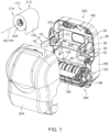
- Figs. 1-5 shows a rolled material lockout system or lockout assembly 500 according to one embodiment of the present application and that is constructed to cooperate with rolled web material dispensers or dispenser assemblies, such as dispenser assembly 28, as shown in Fig. 1 .
- roll lockout system 500 includes a hub 502 that is constructed to cooperate with support arm 22 associated with dispenser assembly 28 and an insert or core insert 504 that is constructed to be received in a cavity or bore 210 of a roll of web material 172 and removeably cooperate with hub 502.
- hub 502 could be constructed in a generally unitary construction to include the structure of support arm 22 associated with facilitating the connection of support arm 22 to housing 202 of dispenser assembly 28.
- Roll support arm 22 is preferably configured to snap-fittingly cooperate with housing 202 such that the support arm 22 extends in a generally linear manner along a length from a first end 30 to an opposing second end 32.
- the first end 30 of the roll support arms 20, 22 preferably includes one or more resilient catches which each preferably include a respective opposing barb 38 formed proximate thereto and that are configured to releasably engage a receiving slot formed in the dispenser housing 202.
- the opposing second end 32 of the roll support arm 22 has a generally arcuate tab 40 that is configured to allow a user to selectively deflect the respective support arm 22 in a generally outward lateral direction relative to a roll of web material 172 to assist in the association of an authorized roll with dispenser assembly 28 and/or the removal of the core of a spent or partially consumed roll therefrom. It is further appreciated that opposing second end 32 of support arm 22 could be configured to cooperate with an interior facing surface of a cover 204 of dispenser assembly 28 when the cover 204 is oriented in a closed position.
- Support arms 20, 22 are constructed to support the opposing ends 212, 214 of a discrete roll of web material 172 in a cantilevered fashion relative to the respective ends 30 of support arms 20, 22 and the housing 202 of dispenser assembly 28 as disclosed further below.
- At least one of arms 20, 22 defines a hub receiving area 42 that is disposed along a front or roll facing surface of the length of the respective roll support arm 20, 22 between the first and second ends 30, 32.
- the hub receiving area 42 includes an optional and preferably circular hollow center or void formed thereat. It should be understood that the present invention is not so limited and that any alternative configuration of the hub receiving area 42 is considered within the scope of the present invention.
- the hub receiving area 42 of one or more of support arms 20, 22 includes a plurality of receiving slots 36 that are annularly disposed proximate the perimeter of the hub receiving area 42 for receiving and mating to the hub 502 as described further below.
- Dispenser assembly 28 includes a feed mechanism 192 that is constructed to cooperate with a free end 195 of roll of web material 172 to effectuate each dispense activity.
- Feed mechanism 192 includes a number of rollers 194, 196 that are constructed to effectuate the dispense activity and thereby unwind the roll of web material 172 during each dispense action.
- Dispenser assembly 28 includes an optional handle 198 that is operational to effectuate manual operation of one or more of rollers 194, 196 to effectuate the dispense activity.
- dispenser assembly 28 could be provided to operate in an automatic or touchless manner via the inclusion of various proximity sensors and drive systems configured to actuation operation of rollers 194, 196 in response to the proximity of a user, or user's hand, relative to a throat or dispense opening 200 of dispenser assembly 28 when in the ready for use configuration or with other manual actuation assemblies such as manually operable lever arms, push paddles, or the like.
- housing 202 of dispenser assembly 28 is generally defined by a cover 204 that movably or pivotably cooperates with a base 206 such that opening of housing 202 of dispenser assembly 28 exposes cavity 190 associated with accepting an authorized roll of web material 172.
- dispenser assembly 28 preferably includes at least two support arms 20, 22 that are disposed on generally opposite lateral sides of cavity 190.
- One of support arms 20, 22 includes a bobbin or a boss 208 that is shaped to cooperate with a respective end of a bore or hollow bore 210 of a roll of web material 172 of indiscriminate source.
- the axially extending bore 210 of the discrete rolls of web material can be defined by a cigarette of the roll of material, a cardboard or other rigid material core tube upon which the web paper material is wound, or other methodologies commonly employed in the web paper roll material forming processes to create the hollow bore associated with the roll of web material.
- boss 208 is shaped to rotationally support a roll of web material from a majority of sources of rolled web material.
- the other of support arms 20, 22 of dispenser assembly 28 is provided with or otherwise constructed to define hub 502.
- support arm 22 includes the hub 502 of lockout system or assembly 500 as authorized roll of web material 172 includes a corresponding core insert 504 that is constructed to removeably cooperate with or engage hub 502.
- hub 502 and insert 504 could be provided at either of the longitudinal ends 212, 214 defined by roll of web material 172 or that dispenser assembly 28 can be readily configured to operate with other lockout systems or assemblies, such as lockout assembly 600 as disclosed further below, via the replacement of the respective lockout enabled support arm 22 and/or engagement of other hubs 502 of hub assemblies 602 as disclosed further below, associated with a discrete respective one of support arms 20, 22.
- dispenser assembly 28 is shown as being equipped with one lockout system or assembly 500, associated with accommodating use of dispenser assembly 28 with a roll of web material 172 having a corresponding respective insert 504 associated with a respective one of lateral or axial ends 212, 214 of authorized roll of web material 172, dispenser assembly 28 could be configured to include a pair of lockout assemblies 500 wherein each lockout assembly 500 is associated with a respective one of support arms 20, 22.
- one of lockout assemblies 500, 600 can be configured to cooperate with only one of the respective axial ends 212, 214 of authorized rolls of web material 172 and in a manner wherein the "overhand” (as shown in Fig. 1 ) or "underhand” unwinding orientation of the authorized roll of web material 172 relative to dispenser assembly 28 creates a desired presentation of the free end 195 of the authorized roll of web material 172 at feed mechanism 192 to effectuate the desired continual sequential dispensing of the web material 172 from dispenser assembly 28.
- housing 202 can be opened and the remaining disposable insert 504, absent its respective supply of rolled web material 172, may be removed from the respective corresponding hub 502 or hub assembly and subsequently discarded and/or recycled, and a new authorized roll of web material 172 with a respective insert 504 orientation and construction in accordance with the respective one or more of support arms 22, 122 to provide the operative cooperation with the respective hub 502 or hub 602 can be associated with underlying dispenser assembly 28 for continued use thereof.
- dispenser assembly 28 can be expeditiously configured to allow operability of the dispenser assembly 28 to dispense only material from rolls of web material that have been previously designated as acceptable for use with the respective dispenser assembly 28.
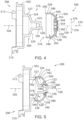
- Figs. 2-5 show the hub 502 of roll lockout assembly or system 500 removed from dispenser assembly 28 and insert 504 removed from the roll of web material 172.
- hub 502 of lockout system 500 is constructed to removeably cooperate with insert 504.
- Hub 502 includes a dispenser facing side 506 having one or more projections 508, 510, 512 that are constructed to tool-lessly and preferably snap-fittingly, wholly or partially rotatably, or otherwise selectively removeably cooperate with at least one of roll support arms 20, 22 has disclosed above. It is appreciated that the size and shape of that portion of hub 502 that is constructed to engage the respective support arm could be provided in various sizes and shapes and constructed to cooperate with support arms having various constructions.
- Hub 502 includes an engagement interface 516 that is constructed to rotationally support and axially cooperate with an engagement interface 518 associated with insert 504.
- Engagement interface 516 associated with hub 502 includes a first portion 520 that is generally defined by a post 522 that extends in an axial direction from a barrel portion 524 of hub 502 along an axis of rotation about axis 526 associated with the axis of rotation associated with a roll of web material 172 supported by lockout system 500.
- Post 522 extends along axial direction of axis 526 between barrel portion 524 and a distal end 528 defined by post 522.
- a channel 530 is formed proximate the cantilevered free end or distal end 528 of post 522 and is constructed a snap-fittingly cooperate with engagement interface 518 defined by insert 504 as disclosed further below.
- Barrel portion 524 of hub 502 includes an outer radial portion 527 that extends an axial direction along axis 526 from the hub facing end of post 522.
- a shoulder 529 is defined by hub 502 and includes one or more ribs 525 that extend in axial direction 526 along the surface associated with radial portion 527 and cooperate with the radially inward facing or directed surface of insert 504 when insert 504 is engaged with hub 502.
- Channel 530 formed in post 522 proximate distal end 528 is constructed to axially cooperate with engagement interface 518 of insert 504 when insert 504 is engaged therewith and oriented for dispensing operation.
- Insert 504 is defined by a body 538 that includes an outwardly directed radial surface 536 that extends between the hub facing end 540 and an opposing or roll of web material facing end 544 of insert 504.
- One or more optional projections 546 extend in a generally outward radial direction relative to surface 536 of insert 504 and engage the radially inward facing surface of roll of web material 172 to secure insert 504 relative to the bore defined by the respective roll of web material, such as roll of web material 172, as disclosed above and as shown in Fig. 1 .
- engagement interface 518 of insert 504 includes a plurality of retainers or fingers 550 that extend from body 538 of insert 504 are oriented in a cantilevered manner between respective discrete support ends 552 and respective distal or free ends 554 associated therewith. That is, although each of fingers 550 are defined by body 538 of insert 504, support ends 552 of fingers 550 are generally positionally associated with one another in a relatively continuous manner whereas each of discrete free ends 554 are independently moveable in an at least inward and outward radial directions relative one another. As disclosed further below, fingers 550 and body 538 are preferably formed to allow a limited degree of axial of axial displacement of free ends 554 relative to one another via an overlapping portion of body 538 of insert 504 as disclosed further below.
- a number of projections 560 extend in a generally inward radial direction toward axis 526 from one or more of fingers 550 and preferably from each of fingers 550.
- insert 504 includes a radially inward directed cavity 562 that axially cooperates with a roll facing end portion 564 of hub 502 when hub 502 and insert 504 are engaged with one another.
- distal end 528 of post 522 is shaped to slideably, and preferably snap-fittingly, cooperate with a cavity 572 defined by the circumference of fingers 550.
- post 522 extends through insert 504, it should be appreciated that the distal end 528 of post 522 is oriented in the bore associated with the roll of web material 172 associated with insert 504.
- insert 504 and hub 502 are engaged with one another such that projections 560 associated with fingers 550 are engaged with channel 530 defined by hub 502, rotational interaction of insert 504 and the roll of web material associated therewith relative to hub 502 is provided in a manner that allows the roll of web material to be rotated but with limited free rotation therebetween after each dispense event.
- Such considerations mitigate instances of dispensing more web material than is desired and/or free spinning of the roll of web material 172 between dispense events.
- hub 502 and insert 504 cooperate with one another so as to define a first bearing surface 580 and a second bearing surface 582 that are formed between the respective adjacent radially facing surfaces of hub 502 and insert 504.
- Bearing surface 580 of roll lockout system 500 is radially nearer axial centerline 526 than bearing surface 582.
- bearing surfaces 580, 582 are also offset relative to one another along axis 526.
- Such a construction provides stable rotational support between insert 504, and a roll of web material associated therewith, and the hub 502 associated with the respective underlying dispenser assembly and/or respective support arm 22, 122 associated therewith and as disclosed further above.
- Bearing surfaces 580, 582 further each provide a generally circumferential rotationally supported interaction between hub 502 and insert 504 when associated with one another and do so in a manner that offsets the rotational support between hub 502 and insert 504 from the axial indexing cooperation associated with the cooperation of projections 560 with channel 530.
- Such considerations provide robust rotational support between hub 502 and insert 504 to better accommodate the mass of a full roll of web material when associated therewith.
- the construction and orientation of the plurality of retainers or fingers 550 associated with roll lockout system 500 can similarly be provided in numerous configurations.
- user manipulation of insert 504 allows fingers 550 to deflect in respective outward radial directions, indicated by arrows 576, to facilitate the removal or disengagement of a discrete insert 504 from the relative underlying hub 502 to accommodate replacement, replenishment, or re-loading of dispenser assembly equipped with hub 502 with a roll of web material having an insert 504 associated with its bore and thereby correlating to an authorized respective roll of web material.
- roll lockout system 500 can be configured with other radially spaced and/or numbers of deflectable retainers or fingers and/or numbers and constructions other than that which is shown in the drawings.
- fingers 550 may be provided in more of fewer fingers 550 than shown in the figures, other radial shapes or sizes, and/or to have projections 560 associated therewith and/or configured to cooperate with a respective portion of insert 504 so as to facilitate the rotational cooperation therebetween, the axially indexed relative position therebetween, and do so in a manner that mitigates axial dissociation or translation of insert 504, and the roll of web material associated therewith, relative to hub 502, during use of the underlying dispenser assembly.
- insert 504 is preferably constructed to interchangeably cooperate with hubs or hub assemblies having constructions that differ from hub 502.
- body 538 of insert 504 of roll lockout system 500 includes an overlapping portion 592 such that body 538 of insert 504 has a generally S or Z shaped cross-sectional shape as the shape or cross-section of insert 504 progresses between end 544 associated with fingers 550 and hub facing end 540 of body 538.
- overlapping portion 592 of insert 504 is may be disposed in alignment with bearing surface 582 or disposed between bearing surfaces 580, 582.
- overlapping portion 592 of insert 504 is disposed between bearing surfaces 580, 582 in both the axial direction associated with axis 526 and the radial direction as indicated by arrows 576. As shown, the separation between adjacent fingers 550 extends between an open end proximate projections 560 and a closed end proximate overlapping portion 592 such that each finger 550 extends in a cantilevered manner relative to the remainder of body 538 from a position proximate overlapping portion 592.
- overlapping portion 592 is formed toward the hub directed side of insert 504 relative to axis 526 and relative to end 544 thereof. That is to say, although insert 504 could be constructed such that overlapping portion 592 be oriented axially outboard of each of bearing surfaces 580, 582, overlapping portion 592 is preferably shaped and positioned to be axially aligned or overlapping in radial directions one of bearing surfaces 580, 582 or located axially therebetween.
- overlapping portion 592 is constructed to maintain the deflectable nature associated with operation of fingers 550 relative to hub 502, facilitate initial alignment of an insert 504 equipped roll of web material with hub 502, attain the desired engagement of a roll of web material with the dispenser, removal of any residual portion associated with a previously consumed roll of web material, and do not otherwise interfere with or detract from the dual bearing surface 580, 582 rotational support associated with the rotational dispensing engagement provided by the selectively severable association of discrete inserts 504 and hub 502.
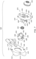
- Figs. 6-9 disclose a roll lockout system 600 according to yet another embodiment of the application.
- lockout system 600 includes a hub 602 that is constructed to selectively cooperate with an insert such as insert 504 in the manner disclosed above.
- insert 504 is constructed to cooperate with a bore 607 of a roll of web material 609 such that, when disposed therein, insert 504 is preferably rendered non-removable from roll of web material 609 save for the depletion thereof and/or destruction of any residual portion of the respective roll of web material such that insert 504 can be considered reusable, recyclable, and/or disposable.
- hub 602 cooperates with a support arm or support arm assembly such that hub 602 is rendered movable relative thereto. As shown, hub 602 cooperates with a support assembly that includes a support arm 606 and a carriage 608 that is engaged therewith. Support arm 606 is defined by a body 610 that is constructed to engage a housing such as housing 202 ( Fig. 1 ) in a manner according to one or more of the methodologies disclosed above.
- body 610 of support arm 606 is constructed to snap-fittingly cooperate with the respecting housing such that a forward oriented hub supporting portion of body 610 is offset from the interior facing surfaces of the housing and such that roll of web material 609 can be supported by hub 602 when hub 602 is engaged with support arm 606.
- a passage 612 is formed through body 610 of support arm 606 and is shaped to cooperate with respective portions of carriage 608 and hub 602 associated therewith as disclosed further below.
- One or more openings 614, 616, 618, 620 are formed through body 610 of support arm 606 and are generally disposed about passage 612.
- One or more handles or tabs 622, 624 extend in an outward radial direction from body 610 relative to passage 612.
- Tabs 622, 624 are generally accessible to the user to facilitate user interaction with support arm 606 and a respective core or cigar associated with a sufficiently depleted roll of web material 609 to assist with the selective separation between hub 602, the core or any portion of a spent roll of web material 609, or an insert 504 that may be associated therewith during reloading of a dispenser assembly equipped therewith.
- carriage 608 is defined by a body 630 having a roll or insert facing surface or side 632 and a support arm facing surface or side 634.
- a passage 636 and one or more openings 638, 640, 642 are formed through body 630 of carriage 608. Openings 638, 640, 642 are generally disposed circumferentially about passage 636 such that each of passage 636 and openings 638, 640, 642 are fluidly isolated from one another and preferably circumferentially bounded by body 630 of carriage 608.
- such a construction maintains a relative rotational orientation of hub 602 relative to carriage 608 when hub 602 is associated therewith and in a manner that accommodates selective axial translation of hub 602 relative to carriage 608 in the manner disclosed further below.
- a wall 644 is generally formed about a perimeter of body 630 and includes one or more projections 646, 648, 650, 652 that extend in an outward axial direction toward support arm 606.
- a catch 654 is formed proximate the distal end of each projection 646, 648, 650, 652.
- Catches 654 and projections 646, 648, 650, 652 are constructed and oriented to cooperate with respective openings 614, 616, 618, 620 defined by support arm 606 such that carriage 608 snap fittingly cooperates therewith such that carriage 608 is positionally fixed relative to support arm 606 when engaged therewith.
- a plurality of projections or arms 660, 662, 664, 666, 668, 670 extend in a rearward axial direction relative to support arm facing side 634 of carriage 608 and are disposed radially proximate openings 638, 640, 642 thereof.
- a barb 672 is formed near the free or distal end 674 of one or more of arms 660, 662, 664, 666, 668, 670.
- Arms 660, 662, 664, 666, 668, 670 are radially spaced from one another and oriented so as to generally define a hub cavity 678 therebetween.
- Arms 660, 662, 664, 666, 668, 670 are deflectable to accommodate association or placement of hub 602 within hub cavity 678 and have an at-rest orientation wherein barbs 672 overlap the radial footprint of hub 602 once hub 602 is position therein.
- hub 602 is insertable into hub cavity 678 from a direction facing support arm 606 such that, once assembled, removal of hub 602 from hub cavity 678 in a direction toward the roll cavity of the dispenser cavity is prevented.
- hub cavity 678 is shaped to support hub 602 such that hub 602 is axially moveable or slideable therein relative to carriage 608.
- hub 602 is defined by a body 680 having a post 682 and one or more projections 684, 686, 688 that are disposed circumferentially thereabout.
- Body 680 of hub 602 defines a cavity 690 that is disposed between a portion of post 682 and generally bounded by projections 684, 686, 688.
- Cavity 690 is shaped to cooperate with a biasing device, such as a spring 692 or the like. When assembled, opposing ends of spring 692 cooperate with carriage 608 and hub 602 to urge hub 602 and carriage 608 toward one another.
- biasing device 692 biases hub 602 relative to carriage 608 and support arm 606 toward an orientation wherein post 682 of hub 602 passes through passage 636 of carriage 608 and extends axially beyond roll facing surface 632 of carriage 608.
- projections 684, 686, 688 of hub 602 pass through respective openings 638, 640, 642 defined by body 630 of carriage 608 and similarly extend axially beyond roll facing surface 632 of carriage 608 such that post 682 and projections 684, 686, 688 are each available for interaction with respective insert 504 and a roll of web material 609 associated therewith.
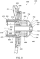
- Such an orientation is shown in Fig. 6 wherein post 682 and projections 684, 686, 688 associated with hub 602 are oriented in an exposed or accessible orientation 696 available for interaction with insert 504 and a respective roll of web material 609 associated therewith.
- post 682 when oriented in the accessible orientation 696, post 682 defines a first bearing surface or interface 700 associated with interaction with insert 504 and projections 684, 686, 688 define a second bearing surface or interface 702 associated with engaging a respective insert 504 having a construction suitable to allow operative rotational but axially fixed engagement therewith such that the projections 560 associated with respective fingers 550 are engaged with a channel 704 defined by post 682.
- Overlapping portion 592 of insert 504 rotationally cooperates with an exterior surface of post 682 and a radially outward directed surface of projections 684, 686, 688 rotationally cooperates with a radially inward facing surface of insert 504.
- bearing surfaces 700, 702 and overlapping portion 592 associated with the cooperation and engagement of insert 504 and hub 602 can be provided in any of the alternate relative constructions, relative to one another and/or each other, disclosed above with respect to the cooperation of insert 504 with hub 502. Regardless of the relative configuration therebetween, biasing device 692 provides sufficient force to tolerate the slideable association of insert 504 with hub 602 such that projections 560 defined by insert 504 can achieve operative engagement with channel 704 defined by hub 602 when an insert constructed for operative engagement with hub 602 is associated therewith.
- Barbs 672 and stop 712 are configured and oriented to prevent continued lateral displacement of hub 602 relative to carriage 608 and to maintain the desired slideable association between post 682 and projections 684, 686, 688 of hub 602 with passage 636 and openings 638, 640, 642 of carriage 608, respectively.
- biasing device 692 acts to return hub 602 from retracted positions relative to carriage 608 toward the exposed, available, or accessible orientation or configuration 696 as the conflicting insert is moved away from or otherwise dissociated from interaction with hub 602.
- the interface therebetween provides a configuration having multiple bearing supports and a methodology that prevents use of dispenser assemblies equipped with hub 602 for use with rolls of web material having inserts that are improperly configured for suitable rotational interaction with hub 602 by physical movement of hub 602 to positions wherein the hub is rendered unavailable for operational interaction with such inserts.
- a web material roll lockout assembly discloses a hub that is constructed to be supported by a dispenser.
- An insert is constructed to rotationally cooperate with the hub when the insert is disposed in a bore of a roll of web material and the roll of web material is associated with the dispenser.
- a channel is formed in a radially outward oriented surface of the hub and positioned such that the channel is formed proximate an end of the hub.
- the assembly includes an insert that is constructed to removeably cooperate with the hub and has an overlapping portion formed between opposing ends of the insert.
- a plurality of projections are defined by the insert and constructed to limit axial translation between the insert and the hub when at least one of the plurality of projections is engaged with the channel and such that the overlapping portion of the insert improves flexibility associated with movement of the plurality of projections.
- a first rotational bearing surface and a second rotational bearing surface are defined between the insert and the hub when the at least one of the plurality of projections is engaged with the channel. The first rotational bearing surface and the second rotational bearing surface are positioned so that the overlapping portion of the insert is disposed therebetween.
- Another embodiment of the present application discloses a method of restricting rolls of web material that can be dispensed from a roll dispenser.
- the method includes providing a hub that defines an axis of rotation of a roll of web material associated with the roll dispenser.
- An insert is provided that has an outer diameter that is constructed to securely engage a bore of a roll of web material and has a radially inward directed shape that slideably cooperates with the hub.
- a portion of the insert is formed to overlap itself as the insert traverses from opposing ends thereof and such that, when the insert is engaged with the hub, cooperation of the insert and the hub restricts axial translation between the hub and the insert and accommodates rotation of the insert relative to the hub during rotation of a roll of web material.
- Engagement of a respective insert with the hub defines at least two bearing surfaces between the insert and the hub wherein each of the at least two bearing surfaces are offset in an axial direction from respective longitudinal ends of the insert and the hub and such that the overlapping portion of the insert is preferably disposed between the at least two bearing surfaces.
- a further embodiment of the present application discloses an insert for use in a roll web material dispenser assembly.
- the insert includes a body that extends between a first end and a second end of the insert.
- An outer surface of the body of the insert is shaped to be received in a roll of web material and an inner surface of the body of the insert is shaped to removeably cooperate with a hub associated with a dispenser and to define at least two bearing surfaces that are axially offset from one another when engaged with the hub.
- the insert includes a plurality of deflectable fingers that are associated with a first end of the body and a projection is associated with at least one of the plurality of deflectable fingers and oriented to engage a groove defined by the hub.
- the body defines an overlapping portion of the insert between the first end and the second end of the insert and is positioned between the at least two bearing surfaces.
- a web material roll lockout assembly having a support arm that is constructed to engage a dispenser housing.
- a carriage is engaged with the support arm and a hub is supported by the carriage and movable relative to the carriage between an exposed position wherein a portion of the hub is accessible and a retracted position wherein the portion of the hub is inaccessible.
- a biasing device is configured to bias the hub toward the exposed position and an insert is constructed to be disposed in a bore of a roll of web material and to slideably cooperate with the hub so that the hub engages the insert without translating the hub relative to the carriage to the retracted position.
- a further embodiment of the present application discloses a web material dispenser lockout system that includes a support assembly that is constructed to cooperate with a dispenser housing.
- a hub slideably engages the support assembly so that the hub is movable between an extended position and a retracted position.
- a biasing device is engaged with the hub and oriented to bias the hub toward the extended position.
- An insert is constructed to be disposed in a bore of a roll of web material and has a radially interior facing geometry that allows the insert to cooperate with the hub without translating the hub toward the retracted position.
Landscapes
- Health & Medical Sciences (AREA)
- Public Health (AREA)
- Replacement Of Web Rolls (AREA)
- Unwinding Webs (AREA)
Claims (12)
- Bahnmaterialrollenverriegelungsbaugruppe (500), umfassend:eine Nabe (502), die dazu konstruiert ist, von einem Spender (28) getragen zu werden;einen Kanal (530), der in einer radial nach außen gerichteten Oberfläche der Nabe gebildet und derart positioniert ist, dass der Kanal in der Nähe eines Endes der Nabe gebildet ist;einen Einsatz (504), der dazu konstruiert ist, entfernbar mit der Nabe zusammenzuwirken und einen Überlappungsabschnitt (592) aufweist, der zwischen entgegengesetzten Enden (540, 544) des Einsatzes derart gebildet ist, dass ein Körper (538) des Einsatzes eine im Allgemeinen S- oder Z-förmige Querschnittsform aufweist, wenn der Querschnitt des Einsatzes zwischen den entgegengesetzten Enden des Einsatzes fortschreitet, wobei sich der Überlappungsabschnitt aufgrund der im Allgemeinen S- oder Z-förmigen Querschnittsform in dem Querschnitt selbst zweimal überlappt;eine Vielzahl von Vorsprüngen (560), die durch den Einsatz definiert und konstruiert ist, um die axiale Translation zwischen dem Einsatz und der Nabe zu begrenzen, wenn mindestens einer der Vielzahl von Vorsprüngen mit dem Kanal in Eingriff steht; undeine erste Drehlageroberfläche (580) und eine zweite Drehlageroberfläche (582), die zwischen dem Einsatz und der Nabe bereitgestellt sind, wenn der mindestens eine der Vielzahl von Vorsprüngen mit dem Kanal in Eingriff steht, wobei die erste Drehlageroberfläche und die zweite Drehlageroberfläche derart positioniert sind, dass der überlappende Abschnitt des Einsatzes dazwischen angeordnet ist.
- Bahnmaterialrollenverriegelungsbaugruppe nach Anspruch 1, wobei die Vielzahl von Vorsprüngen radial voneinander beabstandet ist.
- Bahnmaterialrollenverriegelungsbaugruppe nach Anspruch 1 oder Anspruch 2, wobei jeder der Vielzahl von Vorsprüngen von einem jeweiligen Finger (550) getragen wird.
- Bahnmaterialrollenverriegelungsbaugruppe nach Anspruch 3, wobei jeder Finger in einer hauptsächlich radialen Richtung relativ zu einer Drehachse des Einsatzes auslenkbar ist, und wobei optional oder bevorzugt jeder Finger ferner als ein Ausleger definiert ist, und der mindestens eine Vorsprung an einem freien Ende des jeweiligen Fingers angeordnet ist.
- Bahnmaterialrollenverriegelungsbaugruppe nach Anspruch 1 oder einem vorstehenden Anspruch, wobei der überlappende Abschnitt des Einsatzes zwischen der ersten Drehlageroberfläche und der zweiten Drehlageroberfläche relativ sowohl zu einer axialen Richtung als auch zu einer radialen Richtung liegt, und wobei optional oder bevorzugt die erste Lageroberfläche und die zweite Lageroberfläche sowohl radial als auch axial voneinander beabstandet sind.
- Verfahren zum Einschränken von Bahnmaterialrollen Bahnmaterial (172), die von einem Rollenspender (28) abgegeben werden können, wobei das Verfahren Folgendes umfasst:Bereitstellen einer Nabe (502), die eine Drehachse einer Bahnmaterialrolle definiert, die dem Rollenspender zugeordnet ist; undBereitstellen eines Einsatzes (504), der einen Außendurchmesser aufweist, der derart konstruiert ist, dass er sicher in eine Bohrung einer Bahnmaterialrolle eingreift, eine radial nach innen gerichtete Form aufweist, die gleitend mit der Nabe zusammenwirkt, und einen Überlappungsabschnitt (592) bildet, der zwischen entgegengesetzten Enden (540, 544) des Einsatzes derart ausgebildet ist, dass ein Körper (538) des Einsatzes eine allgemein S- oder Z-förmige Querschnittsform aufweist, wenn der Querschnitt des Einsatzes zwischen den entgegengesetzten Enden des Einsatzes fortschreitet, wobei sich der überlappende Abschnitt aufgrund der im Allgemeinen S- oder Z-förmigen Querschnittsform im Querschnitt zweimal selbst überlappt und derart, dass, wenn der Einsatz mit der Nabe in Eingriff steht, das Zusammenwirken des Einsatzes und der Nabe mindestens zwei Lageroberflächen (560, 580) zwischen dem Einsatz und der Nabe definiert, wobei jede der mindestens zwei Lageroberflächen in axialer Richtung von den jeweiligen Längsenden des Einsatzes und der Nabe versetzt ist und die axiale Translation zwischen der Nabe und dem Einsatz einschränkt und eine Rotation des Einsatzes relativ zu der Nabe während der Drehung einer Bahnmaterialrolle aufnimmt.
- Verfahren nach Anspruch 6, das ferner das Bilden einer Vielzahl von Fingern (550) an dem Einsatz derart umfasst, dass die Vielzahl von Fingern einem gemeinsamen der entgegengesetzten Enden davon zugeordnet ist.
- Verfahren nach Anspruch 7, das ferner das Bilden eines jeweiligen Vorsprungs (560) an mehr als einem der Vielzahl von Fingern des Einsatzes umfasst.
- Verfahren nach Anspruch 8, ferner umfassend:-(i) Bilden des jeweiligen Vorsprungs, um sich in einer radialen Richtung in Bezug auf eine Längsachse des jeweiligen Fingers zu erstrecken, die mit einer Richtung ausgerichtet ist, die der axialen Translation zwischen der Nabe und dem Einsatz zugeordnet ist; und/oder(ii) Konstruieren von mehr als einem der Vielzahl von Fingern, um sich während einer axialen Translation des Einsatzes relativ zu der Nabe in einer hauptsächlich nach außen gerichteten radialen Richtung abzulenken.
- Verfahren nach Anspruch 8 oder Anspruch 9, das ferner das Bilden einer Nut in der Nabe und Ausrichten der Nut umfasst, um den jeweiligen Vorsprung, der durch den Einsatz gebildet wird, aufzunehmen, wenn der Einsatz und die Nabe miteinander in Eingriff stehen.
- Verfahren nach Anspruch 7 oder einem der Ansprüche 8 bis 10, das ferner das Bilden der Vielzahl von Fingern umfasst, um sich von dem Abschnitt des Einsatzes, der sich selbst überlappt, derart zu erstrecken, dass sich jeder der Vielzahl von Fingern in einer freitragenden Weise von dem Abschnitt des Einsatzes, der sich selbst überlappt, unabhängig von anderen der Vielzahl von Fingern erstreckt.
- Verfahren nach Anspruch 6 oder einem der Ansprüche 7 bis 11, das das Versetzen des Abschnitts des Einsatzes, der sich sowohl in der axialen Richtung als auch in einer radialen Richtung selbst überlappt, relativ zu den mindestens zwei Lageroberflächen umfasst.
Applications Claiming Priority (1)
| Application Number | Priority Date | Filing Date | Title |
|---|---|---|---|
| US16/828,359 US11071417B2 (en) | 2019-03-28 | 2020-03-24 | Rolled web material dispenser material lockout systems |
Publications (2)
| Publication Number | Publication Date |
|---|---|
| EP3884828A1 EP3884828A1 (de) | 2021-09-29 |
| EP3884828B1 true EP3884828B1 (de) | 2023-11-15 |
Family
ID=73857144
Family Applications (1)
| Application Number | Title | Priority Date | Filing Date |
|---|---|---|---|
| EP20217080.9A Active EP3884828B1 (de) | 2020-03-24 | 2020-12-23 | Materialverriegelungssysteme für walzgutspender |
Country Status (5)
| Country | Link |
|---|---|
| EP (1) | EP3884828B1 (de) |
| CA (1) | CA3114970C (de) |
| ES (1) | ES2967888T3 (de) |
| MX (1) | MX2021003181A (de) |
| PT (1) | PT3884828T (de) |
Family Cites Families (2)
| Publication number | Priority date | Publication date | Assignee | Title |
|---|---|---|---|---|
| US6027069A (en) * | 1998-03-09 | 2000-02-22 | Huang; Harrison | Plastic membrane dispenser |
| US9770142B2 (en) * | 2013-12-02 | 2017-09-26 | Dispensing Dynamics International, Llc | Multi-piece support for paper roll product |
-
2020
- 2020-12-23 ES ES20217080T patent/ES2967888T3/es active Active
- 2020-12-23 PT PT202170809T patent/PT3884828T/pt unknown
- 2020-12-23 EP EP20217080.9A patent/EP3884828B1/de active Active
-
2021
- 2021-03-18 MX MX2021003181A patent/MX2021003181A/es unknown
- 2021-03-19 CA CA3114970A patent/CA3114970C/en active Active
Also Published As
| Publication number | Publication date |
|---|---|
| MX2021003181A (es) | 2021-09-27 |
| ES2967888T3 (es) | 2024-05-06 |
| CA3114970C (en) | 2026-03-31 |
| CA3114970A1 (en) | 2021-09-24 |
| EP3884828A1 (de) | 2021-09-29 |
| PT3884828T (pt) | 2024-01-15 |
Similar Documents
| Publication | Publication Date | Title |
|---|---|---|
| EP3714752B1 (de) | Materialverriegelungssysteme für walzgutspender | |
| US11224316B2 (en) | Rolled web material dispenser material lockout systems | |
| US6607160B2 (en) | Easy loading dispenser | |
| CN103930011B (zh) | 片材制品分配器 | |
| AU2002245729A1 (en) | Easy loading dispenser | |
| US20050167544A1 (en) | Three roll tissue dispenser | |
| CA3055841C (en) | Spindle assembly for sheet product dispensers | |
| US3612423A (en) | Rolled paper dispenser | |
| US11083348B2 (en) | Rolled web material dispenser material lockout systems | |
| US11071417B2 (en) | Rolled web material dispenser material lockout systems | |
| US20200102180A1 (en) | Spindles and dispensers for sheet product | |
| GB2472564A (en) | Mounting for sheet rolls to be used only with dispenser for which they are intended | |
| CA3114970C (en) | Rolled web material dispenser material lockout systems | |
| EP3329819B1 (de) | Spender für eine rolle von kernlosem bahnmaterial | |
| EP3884827B1 (de) | Materialverriegelungssysteme für walzgutspender | |
| CA3071506C (en) | Carousel style dispenser | |
| JP2002525148A (ja) | 前部にリールを備えた拭き取り材料のための分配機械 | |
| US12440073B1 (en) | Tube holder with retractable barrier(s) | |
| EP1665971B1 (de) | Klinkeanschlaganondnung zur Verwendung in einer Abgabevorrichtung |
Legal Events
| Date | Code | Title | Description |
|---|---|---|---|
| PUAI | Public reference made under article 153(3) epc to a published international application that has entered the european phase |
Free format text: ORIGINAL CODE: 0009012 |
|
| STAA | Information on the status of an ep patent application or granted ep patent |
Free format text: STATUS: THE APPLICATION HAS BEEN PUBLISHED |
|
| AK | Designated contracting states |
Kind code of ref document: A1 Designated state(s): AL AT BE BG CH CY CZ DE DK EE ES FI FR GB GR HR HU IE IS IT LI LT LU LV MC MK MT NL NO PL PT RO RS SE SI SK SM TR |
|
| STAA | Information on the status of an ep patent application or granted ep patent |
Free format text: STATUS: REQUEST FOR EXAMINATION WAS MADE |
|
| 17P | Request for examination filed |
Effective date: 20220329 |
|
| RBV | Designated contracting states (corrected) |
Designated state(s): AL AT BE BG CH CY CZ DE DK EE ES FI FR GB GR HR HU IE IS IT LI LT LU LV MC MK MT NL NO PL PT RO RS SE SI SK SM TR |
|
| GRAP | Despatch of communication of intention to grant a patent |
Free format text: ORIGINAL CODE: EPIDOSNIGR1 |
|
| STAA | Information on the status of an ep patent application or granted ep patent |
Free format text: STATUS: GRANT OF PATENT IS INTENDED |
|
| RIC1 | Information provided on ipc code assigned before grant |
Ipc: B65H 75/18 20060101ALI20230512BHEP Ipc: B65H 16/06 20060101ALI20230512BHEP Ipc: B65H 16/00 20060101ALI20230512BHEP Ipc: A47K 10/38 20060101AFI20230512BHEP |
|
| INTG | Intention to grant announced |
Effective date: 20230609 |
|
| GRAS | Grant fee paid |
Free format text: ORIGINAL CODE: EPIDOSNIGR3 |
|
| GRAA | (expected) grant |
Free format text: ORIGINAL CODE: 0009210 |
|
| STAA | Information on the status of an ep patent application or granted ep patent |
Free format text: STATUS: THE PATENT HAS BEEN GRANTED |
|
| AK | Designated contracting states |
Kind code of ref document: B1 Designated state(s): AL AT BE BG CH CY CZ DE DK EE ES FI FR GB GR HR HU IE IS IT LI LT LU LV MC MK MT NL NO PL PT RO RS SE SI SK SM TR |
|
| REG | Reference to a national code |
Ref country code: CH Ref legal event code: EP Ref country code: GB Ref legal event code: FG4D |
|
| REG | Reference to a national code |
Ref country code: DE Ref legal event code: R096 Ref document number: 602020021036 Country of ref document: DE |
|
| P01 | Opt-out of the competence of the unified patent court (upc) registered |
Effective date: 20231101 |
|
| REG | Reference to a national code |
Ref country code: IE Ref legal event code: FG4D |
|
| REG | Reference to a national code |
Ref country code: NL Ref legal event code: FP |
|
| REG | Reference to a national code |
Ref country code: PT Ref legal event code: SC4A Ref document number: 3884828 Country of ref document: PT Date of ref document: 20240115 Kind code of ref document: T Free format text: AVAILABILITY OF NATIONAL TRANSLATION Effective date: 20240108 |
|
| REG | Reference to a national code |
Ref country code: LT Ref legal event code: MG9D |
|
| PG25 | Lapsed in a contracting state [announced via postgrant information from national office to epo] |
Ref country code: GR Free format text: LAPSE BECAUSE OF FAILURE TO SUBMIT A TRANSLATION OF THE DESCRIPTION OR TO PAY THE FEE WITHIN THE PRESCRIBED TIME-LIMIT Effective date: 20240216 |
|
| PG25 | Lapsed in a contracting state [announced via postgrant information from national office to epo] |
Ref country code: IS Free format text: LAPSE BECAUSE OF FAILURE TO SUBMIT A TRANSLATION OF THE DESCRIPTION OR TO PAY THE FEE WITHIN THE PRESCRIBED TIME-LIMIT Effective date: 20240315 |
|
| PG25 | Lapsed in a contracting state [announced via postgrant information from national office to epo] |
Ref country code: LT Free format text: LAPSE BECAUSE OF FAILURE TO SUBMIT A TRANSLATION OF THE DESCRIPTION OR TO PAY THE FEE WITHIN THE PRESCRIBED TIME-LIMIT Effective date: 20231115 |
|
| REG | Reference to a national code |
Ref country code: AT Ref legal event code: MK05 Ref document number: 1630961 Country of ref document: AT Kind code of ref document: T Effective date: 20231115 |
|
| PG25 | Lapsed in a contracting state [announced via postgrant information from national office to epo] |
Ref country code: AT Free format text: LAPSE BECAUSE OF FAILURE TO SUBMIT A TRANSLATION OF THE DESCRIPTION OR TO PAY THE FEE WITHIN THE PRESCRIBED TIME-LIMIT Effective date: 20231115 |
|
| PG25 | Lapsed in a contracting state [announced via postgrant information from national office to epo] |
Ref country code: LT Free format text: LAPSE BECAUSE OF FAILURE TO SUBMIT A TRANSLATION OF THE DESCRIPTION OR TO PAY THE FEE WITHIN THE PRESCRIBED TIME-LIMIT Effective date: 20231115 Ref country code: IS Free format text: LAPSE BECAUSE OF FAILURE TO SUBMIT A TRANSLATION OF THE DESCRIPTION OR TO PAY THE FEE WITHIN THE PRESCRIBED TIME-LIMIT Effective date: 20240315 Ref country code: GR Free format text: LAPSE BECAUSE OF FAILURE TO SUBMIT A TRANSLATION OF THE DESCRIPTION OR TO PAY THE FEE WITHIN THE PRESCRIBED TIME-LIMIT Effective date: 20240216 Ref country code: BG Free format text: LAPSE BECAUSE OF FAILURE TO SUBMIT A TRANSLATION OF THE DESCRIPTION OR TO PAY THE FEE WITHIN THE PRESCRIBED TIME-LIMIT Effective date: 20240215 Ref country code: AT Free format text: LAPSE BECAUSE OF FAILURE TO SUBMIT A TRANSLATION OF THE DESCRIPTION OR TO PAY THE FEE WITHIN THE PRESCRIBED TIME-LIMIT Effective date: 20231115 |
|
| REG | Reference to a national code |
Ref country code: ES Ref legal event code: FG2A Ref document number: 2967888 Country of ref document: ES Kind code of ref document: T3 Effective date: 20240506 |
|
| PG25 | Lapsed in a contracting state [announced via postgrant information from national office to epo] |
Ref country code: SE Free format text: LAPSE BECAUSE OF FAILURE TO SUBMIT A TRANSLATION OF THE DESCRIPTION OR TO PAY THE FEE WITHIN THE PRESCRIBED TIME-LIMIT Effective date: 20231115 Ref country code: RS Free format text: LAPSE BECAUSE OF FAILURE TO SUBMIT A TRANSLATION OF THE DESCRIPTION OR TO PAY THE FEE WITHIN THE PRESCRIBED TIME-LIMIT Effective date: 20231115 Ref country code: PL Free format text: LAPSE BECAUSE OF FAILURE TO SUBMIT A TRANSLATION OF THE DESCRIPTION OR TO PAY THE FEE WITHIN THE PRESCRIBED TIME-LIMIT Effective date: 20231115 Ref country code: NO Free format text: LAPSE BECAUSE OF FAILURE TO SUBMIT A TRANSLATION OF THE DESCRIPTION OR TO PAY THE FEE WITHIN THE PRESCRIBED TIME-LIMIT Effective date: 20240215 Ref country code: LV Free format text: LAPSE BECAUSE OF FAILURE TO SUBMIT A TRANSLATION OF THE DESCRIPTION OR TO PAY THE FEE WITHIN THE PRESCRIBED TIME-LIMIT Effective date: 20231115 Ref country code: HR Free format text: LAPSE BECAUSE OF FAILURE TO SUBMIT A TRANSLATION OF THE DESCRIPTION OR TO PAY THE FEE WITHIN THE PRESCRIBED TIME-LIMIT Effective date: 20231115 |
|
| PG25 | Lapsed in a contracting state [announced via postgrant information from national office to epo] |
Ref country code: DK Free format text: LAPSE BECAUSE OF FAILURE TO SUBMIT A TRANSLATION OF THE DESCRIPTION OR TO PAY THE FEE WITHIN THE PRESCRIBED TIME-LIMIT Effective date: 20231115 |
|
| PG25 | Lapsed in a contracting state [announced via postgrant information from national office to epo] |
Ref country code: CZ Free format text: LAPSE BECAUSE OF FAILURE TO SUBMIT A TRANSLATION OF THE DESCRIPTION OR TO PAY THE FEE WITHIN THE PRESCRIBED TIME-LIMIT Effective date: 20231115 |
|
| PG25 | Lapsed in a contracting state [announced via postgrant information from national office to epo] |
Ref country code: SK Free format text: LAPSE BECAUSE OF FAILURE TO SUBMIT A TRANSLATION OF THE DESCRIPTION OR TO PAY THE FEE WITHIN THE PRESCRIBED TIME-LIMIT Effective date: 20231115 |
|
| PG25 | Lapsed in a contracting state [announced via postgrant information from national office to epo] |
Ref country code: SM Free format text: LAPSE BECAUSE OF FAILURE TO SUBMIT A TRANSLATION OF THE DESCRIPTION OR TO PAY THE FEE WITHIN THE PRESCRIBED TIME-LIMIT Effective date: 20231115 Ref country code: SK Free format text: LAPSE BECAUSE OF FAILURE TO SUBMIT A TRANSLATION OF THE DESCRIPTION OR TO PAY THE FEE WITHIN THE PRESCRIBED TIME-LIMIT Effective date: 20231115 Ref country code: RO Free format text: LAPSE BECAUSE OF FAILURE TO SUBMIT A TRANSLATION OF THE DESCRIPTION OR TO PAY THE FEE WITHIN THE PRESCRIBED TIME-LIMIT Effective date: 20231115 Ref country code: IT Free format text: LAPSE BECAUSE OF NON-PAYMENT OF DUE FEES Effective date: 20231223 Ref country code: EE Free format text: LAPSE BECAUSE OF FAILURE TO SUBMIT A TRANSLATION OF THE DESCRIPTION OR TO PAY THE FEE WITHIN THE PRESCRIBED TIME-LIMIT Effective date: 20231115 Ref country code: DK Free format text: LAPSE BECAUSE OF FAILURE TO SUBMIT A TRANSLATION OF THE DESCRIPTION OR TO PAY THE FEE WITHIN THE PRESCRIBED TIME-LIMIT Effective date: 20231115 Ref country code: CZ Free format text: LAPSE BECAUSE OF FAILURE TO SUBMIT A TRANSLATION OF THE DESCRIPTION OR TO PAY THE FEE WITHIN THE PRESCRIBED TIME-LIMIT Effective date: 20231115 |
|
| REG | Reference to a national code |
Ref country code: CH Ref legal event code: PL |
|
| REG | Reference to a national code |
Ref country code: DE Ref legal event code: R097 Ref document number: 602020021036 Country of ref document: DE |
|
| PG25 | Lapsed in a contracting state [announced via postgrant information from national office to epo] |
Ref country code: LU Free format text: LAPSE BECAUSE OF NON-PAYMENT OF DUE FEES Effective date: 20231223 |
|
| PG25 | Lapsed in a contracting state [announced via postgrant information from national office to epo] |
Ref country code: MC Free format text: LAPSE BECAUSE OF FAILURE TO SUBMIT A TRANSLATION OF THE DESCRIPTION OR TO PAY THE FEE WITHIN THE PRESCRIBED TIME-LIMIT Effective date: 20231115 |
|
| PG25 | Lapsed in a contracting state [announced via postgrant information from national office to epo] |
Ref country code: MC Free format text: LAPSE BECAUSE OF FAILURE TO SUBMIT A TRANSLATION OF THE DESCRIPTION OR TO PAY THE FEE WITHIN THE PRESCRIBED TIME-LIMIT Effective date: 20231115 Ref country code: LU Free format text: LAPSE BECAUSE OF NON-PAYMENT OF DUE FEES Effective date: 20231223 |
|
| PLBE | No opposition filed within time limit |
Free format text: ORIGINAL CODE: 0009261 |
|
| STAA | Information on the status of an ep patent application or granted ep patent |
Free format text: STATUS: NO OPPOSITION FILED WITHIN TIME LIMIT |
|
| PG25 | Lapsed in a contracting state [announced via postgrant information from national office to epo] |
Ref country code: CH Free format text: LAPSE BECAUSE OF NON-PAYMENT OF DUE FEES Effective date: 20231231 |
|
| 26N | No opposition filed |
Effective date: 20240819 |
|
| PG25 | Lapsed in a contracting state [announced via postgrant information from national office to epo] |
Ref country code: SI Free format text: LAPSE BECAUSE OF FAILURE TO SUBMIT A TRANSLATION OF THE DESCRIPTION OR TO PAY THE FEE WITHIN THE PRESCRIBED TIME-LIMIT Effective date: 20231115 |
|
| PG25 | Lapsed in a contracting state [announced via postgrant information from national office to epo] |
Ref country code: SI Free format text: LAPSE BECAUSE OF FAILURE TO SUBMIT A TRANSLATION OF THE DESCRIPTION OR TO PAY THE FEE WITHIN THE PRESCRIBED TIME-LIMIT Effective date: 20231115 Ref country code: CH Free format text: LAPSE BECAUSE OF NON-PAYMENT OF DUE FEES Effective date: 20231231 |
|
| PG25 | Lapsed in a contracting state [announced via postgrant information from national office to epo] |
Ref country code: IT Free format text: LAPSE BECAUSE OF NON-PAYMENT OF DUE FEES Effective date: 20231223 |
|
| PGRI | Patent reinstated in contracting state [announced from national office to epo] |
Ref country code: IT Effective date: 20240102 |
|
| PG25 | Lapsed in a contracting state [announced via postgrant information from national office to epo] |
Ref country code: IT Free format text: LAPSE BECAUSE OF NON-PAYMENT OF DUE FEES Effective date: 20231223 |
|
| PGRI | Patent reinstated in contracting state [announced from national office to epo] |
Ref country code: IT Effective date: 20240102 |
|
| PG25 | Lapsed in a contracting state [announced via postgrant information from national office to epo] |
Ref country code: FI Free format text: LAPSE BECAUSE OF FAILURE TO SUBMIT A TRANSLATION OF THE DESCRIPTION OR TO PAY THE FEE WITHIN THE PRESCRIBED TIME-LIMIT Effective date: 20231115 |
|
| PG25 | Lapsed in a contracting state [announced via postgrant information from national office to epo] |
Ref country code: CY Free format text: LAPSE BECAUSE OF FAILURE TO SUBMIT A TRANSLATION OF THE DESCRIPTION OR TO PAY THE FEE WITHIN THE PRESCRIBED TIME-LIMIT; INVALID AB INITIO Effective date: 20201223 |
|
| PG25 | Lapsed in a contracting state [announced via postgrant information from national office to epo] |
Ref country code: HU Free format text: LAPSE BECAUSE OF FAILURE TO SUBMIT A TRANSLATION OF THE DESCRIPTION OR TO PAY THE FEE WITHIN THE PRESCRIBED TIME-LIMIT; INVALID AB INITIO Effective date: 20201223 |
|
| PG25 | Lapsed in a contracting state [announced via postgrant information from national office to epo] |
Ref country code: TR Free format text: LAPSE BECAUSE OF FAILURE TO SUBMIT A TRANSLATION OF THE DESCRIPTION OR TO PAY THE FEE WITHIN THE PRESCRIBED TIME-LIMIT Effective date: 20231115 |
|
| PGFP | Annual fee paid to national office [announced via postgrant information from national office to epo] |
Ref country code: PT Payment date: 20251202 Year of fee payment: 6 |
|
| PGFP | Annual fee paid to national office [announced via postgrant information from national office to epo] |
Ref country code: GB Payment date: 20251125 Year of fee payment: 6 |
|
| PGFP | Annual fee paid to national office [announced via postgrant information from national office to epo] |
Ref country code: IT Payment date: 20251218 Year of fee payment: 6 |
|
| PGFP | Annual fee paid to national office [announced via postgrant information from national office to epo] |
Ref country code: NL Payment date: 20251222 Year of fee payment: 6 Ref country code: FR Payment date: 20251223 Year of fee payment: 6 |
|
| PGFP | Annual fee paid to national office [announced via postgrant information from national office to epo] |
Ref country code: IE Payment date: 20251218 Year of fee payment: 6 |
|
| PGFP | Annual fee paid to national office [announced via postgrant information from national office to epo] |
Ref country code: ES Payment date: 20260122 Year of fee payment: 6 |
|
| PGFP | Annual fee paid to national office [announced via postgrant information from national office to epo] |
Ref country code: DE Payment date: 20251229 Year of fee payment: 6 |
|
| PGFP | Annual fee paid to national office [announced via postgrant information from national office to epo] |
Ref country code: BE Payment date: 20260109 Year of fee payment: 6 |