EP3884478B1 - Handheld laser -based vehicle speed measurement device incorporating an automatic number plate recognition (anpr) function - Google Patents
Handheld laser -based vehicle speed measurement device incorporating an automatic number plate recognition (anpr) function Download PDFInfo
- Publication number
- EP3884478B1 EP3884478B1 EP19886437.3A EP19886437A EP3884478B1 EP 3884478 B1 EP3884478 B1 EP 3884478B1 EP 19886437 A EP19886437 A EP 19886437A EP 3884478 B1 EP3884478 B1 EP 3884478B1
- Authority
- EP
- European Patent Office
- Prior art keywords
- speed
- anpr
- laser
- target vehicle
- number plate
- Prior art date
- Legal status (The legal status is an assumption and is not a legal conclusion. Google has not performed a legal analysis and makes no representation as to the accuracy of the status listed.)
- Active
Links
Images



Classifications
-
- G—PHYSICS
- G08—SIGNALLING
- G08G—TRAFFIC CONTROL SYSTEMS
- G08G1/00—Traffic control systems for road vehicles
- G08G1/01—Detecting movement of traffic to be counted or controlled
- G08G1/052—Detecting movement of traffic to be counted or controlled with provision for determining speed or overspeed
- G08G1/054—Detecting movement of traffic to be counted or controlled with provision for determining speed or overspeed photographing overspeeding vehicles
-
- G—PHYSICS
- G01—MEASURING; TESTING
- G01S—RADIO DIRECTION-FINDING; RADIO NAVIGATION; DETERMINING DISTANCE OR VELOCITY BY USE OF RADIO WAVES; LOCATING OR PRESENCE-DETECTING BY USE OF THE REFLECTION OR RERADIATION OF RADIO WAVES; ANALOGOUS ARRANGEMENTS USING OTHER WAVES
- G01S17/00—Systems using the reflection or reradiation of electromagnetic waves other than radio waves, e.g. lidar systems
- G01S17/02—Systems using the reflection of electromagnetic waves other than radio waves
- G01S17/50—Systems of measurement based on relative movement of target
- G01S17/58—Velocity or trajectory determination systems; Sense-of-movement determination systems
-
- G—PHYSICS
- G01—MEASURING; TESTING
- G01S—RADIO DIRECTION-FINDING; RADIO NAVIGATION; DETERMINING DISTANCE OR VELOCITY BY USE OF RADIO WAVES; LOCATING OR PRESENCE-DETECTING BY USE OF THE REFLECTION OR RERADIATION OF RADIO WAVES; ANALOGOUS ARRANGEMENTS USING OTHER WAVES
- G01S17/00—Systems using the reflection or reradiation of electromagnetic waves other than radio waves, e.g. lidar systems
- G01S17/86—Combinations of lidar systems with systems other than lidar, radar or sonar, e.g. with direction finders
-
- G—PHYSICS
- G01—MEASURING; TESTING
- G01S—RADIO DIRECTION-FINDING; RADIO NAVIGATION; DETERMINING DISTANCE OR VELOCITY BY USE OF RADIO WAVES; LOCATING OR PRESENCE-DETECTING BY USE OF THE REFLECTION OR RERADIATION OF RADIO WAVES; ANALOGOUS ARRANGEMENTS USING OTHER WAVES
- G01S17/00—Systems using the reflection or reradiation of electromagnetic waves other than radio waves, e.g. lidar systems
- G01S17/88—Lidar systems specially adapted for specific applications
-
- G—PHYSICS
- G08—SIGNALLING
- G08G—TRAFFIC CONTROL SYSTEMS
- G08G1/00—Traffic control systems for road vehicles
- G08G1/01—Detecting movement of traffic to be counted or controlled
- G08G1/04—Detecting movement of traffic to be counted or controlled using optical or ultrasonic detectors
Definitions
- TruCAM ® a registered trademark of Laser Technology, Inc.
- the TruCAM device collects and stores a complete chain of video evidence for both speeding and tailgating violations along with a high-resolution image that identifies the vehicle make, model and license plate number.
- Representative of the technology embodied in the TruCAM devices is that disclosed in, for example, in U.S. Pat. No. 7,920,251 issuing Apr. 5, 2011 for: "Integrated Still Image, Motion Video and Speed Measurement System” ; U.S. Pat. No. 8,311,343 issuing Nov.
- Laser-based speed measurement devices operate to calculate distance by measuring the time of flight of very short pulses of infrared light. That is, a measurement is made as to the time it takes one or more laser pulses to travel to a target vehicle and back with a precision time base. With knowledge of the constant speed of light, the distance the laser pulses have traveled can then be calculated. If the speed gun takes, for example, a thousand samples per second, its processor can compare the change in distance between successive samples and thereby calculate the speed of the target vehicle. By taking several hundred samples over the course of a fraction of a second or so, the accuracy can be extremely high.
- ANPR automatic number plate recognition
- closed-circuit television fixed traffic enforcement cameras, or other cameras specifically designed for the task.
- ANPR is used by police forces around the world for law enforcement purposes, including to check if a vehicle is currently being sought for whatever reason, registered and/or licensed. It is also used for electronic toll collection on pay-per-use roads and as a method of cataloguing the movements of traffic, for example by highways agencies.
- Automatic number plate recognition can be used to store the images captured by the cameras as well as the text from the license plate, with some configurable to store a photograph of the driver.
- Systems may also employ infrared lighting to allow the camera to take the picture at any time of day or night.
- US 2004/101166 A1 describes a speed measurement system for measuring speeds of vehicles, capturing images of vehicles, and detecting violation of stop sign and traffic signal laws.
- the system includes a laser speed detector for determining a speed of a vehicle adjacent a stop sign. When a speed is determined, the detector generates a speed signal.
- the system includes a camera generally aligned with the speed detector operable to capture and store digital still images of vehicles in memory. The camera is programmed to respond to an image capture signal to generate and transmit a digital image file including a still image of the vehicle targeted by the detector.
- a portable processor is linked to the speed detector and the camera to first receive the speed signal, to compare the detected speed with a threshold speed, to transmit an image capture signal to the camera, and to receive the image file from the camera.
- ANPR functionality has not been able to be implemented in a handheld speed measurement device, whether implemented in conjunction with radar or laser-based speed measurement devices.
- all existing ANPR equipment utilize and assume predetermined geometries between the instrument and the vehicle license plate (inclusive of optical parameters and distances to plate) in order to properly function.
- such existing products are not capable of accurately functioning when tilting of the device must be compensated for as in the operation of a handheld device such as a laser-based speed measurement device as disclosed herein.
- Typical low-cost cameras such as those incorporated in "Body CAMs” and smart phones, utilize what are known as rolling shutters. Such cameras take an image line-by-line instead of the whole scene at once.
- a conventional "wet film” a "global shutter” is employed wherein the camera shutter is mechanically opened.
- modern cameras utilize an electronic shutter so a line-by-line technique is employed.
- the technique of the present invention incorporates rolling shutter compensation and pre-processing of the license plate image.
- a handheld laser-based speed gun comprising a processor and laser signal transmitting and receiving sections coupled to the processor for determining a speed of a target vehicle based on changes in distance between the speed gun and the target vehicle over time.
- the speed gun further comprises a camera module coupled to the processor for capturing images of the target vehicle number plate and an automatic number plate recognition (ANPR) module is also coupled to the processor in operative association with said camera module.
- ANPR automatic number plate recognition
- Also particularly disclosed herein is a method for identifying a vehicle number plate of interest with a handheld distance ranging device comprising an image sensor.
- the method comprises capturing an image of the vehicle number plate; compensating the captured image to account for a determined distance of the ranging device to the vehicle number plate to produce a compensated image; and determining if the compensated image resides in a database of the vehicle number plates of interest.
- FIG. 1 an isometric view of a representative laser-based speed gun 100 is shown incorporating a camera module and folded optical system 120 incorporating an ANPR function in accordance with the principles of the present invention.
- the laser-based speed gun 100 comprises a housing 102 and associated handle 104 for handheld operation.
- a trigger 106 is provided to initiate the transmission and reception of laser pulses toward a moving object, such as a vehicle, as well as initiate the recording of video of the object in conjunction with the camera module and folded optical system 120.
- the laser-based speed gun 100 includes a display 108, user input and selection elements 110 as well as target vehicle sighting optics 112.
- a representative laser-based speed gun may be implemented in accordance with the disclosure of commonly owned U.S. Patent No. 10,146,103 issuing December 4, 2018 for "Camera Module and Folded Optical System for Laser-Based Speed Gun ", the disclosure of which is specifically incorporated by this reference in its entirety as if fully set forth herein.
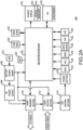
- Fig. 2A a representative functional block diagram of the laser-based speed gun 200 of the preceding figure in accordance with the principles of the present invention is shown.
- the exemplary speed gun 100 comprises a microprocessor 202 or central processing unit (CPU) with an associated oscillator 204 (where required) for providing clocking signals to the microprocessor 202.
- a battery and power management section 206 supplies operating power to the microprocessor 202 and various other speed gun subsystems (not shown) as well as the high voltage (HV) power supply 208 which provides operating voltage to a laser transmit section 210 and associated laser diode as well as a laser receive section 212 and associated photodiode.
- HV high voltage
- the laser receive section 212 receives a portion of the laser energy transmitted by the laser transmit section 210 as reflected by a target vehicle to a photodiode and provides the return signals to a signal/noise (S/N) discriminator section 214 in order to separate true return pulses from any associated noise.
- a timing section 216 accurately measures the time between the transmission of laser pulses from the laser transmit section 210 and the reception of the same target vehicle reflected pulses at the laser receive section 212 to determine, in conjunction with the microprocessor 202, the varying distance, and hence the speed, of the particular target vehicle towards which the speed gun 200 is aimed.
- a fire button 222 is coupled to the battery and power management section 206 and is operable by a user of the speed gun 200 in conjunction with the microprocessor 202 to determine when to emit pulses toward a target vehicle from the laser transmit section 210.
- the speed gun 200 may also incorporate a user viewable in-sight display 218 implemented in conjunction with a novel and proprietary backlighting technique which may include a view of the target vehicle in conjunction with an aiming reticle as well as information regarding the range to, and/or speed of, the target vehicle, battery condition and other information.
- the speed gun 200 may also comprise a touchscreen display to allow user to provide inputs to the speed gun 200 in conjunction with, or as an alternative to, an input/output (I/O) section 220.
- I/O input/output
- the I/O section 220 may further comprise a keypad or other means of communicating information to or from the microprocessor 202 including wired connections such as a universal serial bus (USB) and the like as well as wireless connections such as an IEEE 802.11 (WiFi), or other wireless local area network (WLAN) transceiver; a Bluetooth transceiver or other personal area network (PAN) system for wirelessly exchanging data over short distances; and/or another near field communication (NFC) transceiver (inclusive of infrared (IR) coupling) for wirelessly coupling the speed gun 200 to external devices or data storage elements.
- wired connections such as a universal serial bus (USB) and the like as well as wireless connections such as an IEEE 802.11 (WiFi), or other wireless local area network (WLAN) transceiver; a Bluetooth transceiver or other personal area network (PAN) system for wirelessly exchanging data over short distances; and/or another near field communication (NFC) transceiver (inclusive of infrare
- the speed gun 200 may further include one or more of additional input modules such as an inclinometer 224, accelerometer, 226, magnetic sensor 228 (e.g. a compass) and/or rate gyro 230.
- additional input modules such as an inclinometer 224, accelerometer, 226, magnetic sensor 228 (e.g. a compass) and/or rate gyro 230.
- the speed gun 200 is illustrated as incorporating a backlight 232.
- the backlight 232 may be advantageously provided in accordance with the specification and teachings of commonly owned U.S. Patent 9,964,805 issued on May 8, 2018 for: “Backlighting Technique for Liquid Crystal and Other Displays in Electronic Speed guns ", the disclosure of which is specifically incorporated by this reference in its entirety as if fully set forth herein.
- the speed gun 200 may comprise a reticle 234 interposed between the backlight and the in-sight display 218 as is more fully described in the aforementioned '805 patent.
- a global positioning satellite (GPS) module 236 may also form a portion of the speed gun 200 to provide information to the microprocessor 202 as to the specific geographic position of the speed gun 200.
- the speed gun 200 may further include an NFC module 238 capable of enabling external bidirectional communication with the speed gun 200 via Bluetooth, WiFi and the like in conjunction with a smartphone, tablet device, computer laptop etc.
- the speed gun 200 may further be configured to provide an augmented reality display to a user by the additional provision of an advanced in-scope display or camera module 240 and view screen 242.
- an advanced in-scope display or camera module 240 and view screen 242 In this manner, by angularly scanning the speed gun 200 about a target vehicle, other features and objects in the surrounding scene can be displayed in the view screen 242 (or in-sight display 218 and/or the screen of an associated smartphone, tablet device or laptop) to a user of the speed gun 200 along with the determined distances to such additional features and objects to provide additional terrain context over and above the speed of, or distance to, the desired target vehicle.
- Such features and objects might be, depending on the particular application of the speed gun 100 trees, highway overpasses, signs, buildings and the like.
- the in-scope display or camera module 140 is then operational to log the surrounding features and objects, and their distances determined by the laser-based speed gun 200 and this information displayed in a picture to a user of the speed gun 200, whether on the speed gun itself or on the screen of any associated device.
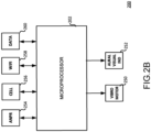
- FIG. 2B an additional representative portion of the functional block diagram of the laser-based speed gun 200 of the preceding figure is shown illustrative of an embodiment of the present invention which may further include a vibro-motor 250 and one or more audio and/or visual indicators 252 to provide physical, haptic and audible and/or visible feedback to the user of a particular target vehicle number plate being of interest.
- a vibro-motor 250 and one or more audio and/or visual indicators 252 to provide physical, haptic and audible and/or visible feedback to the user of a particular target vehicle number plate being of interest.
- a laser-based speed gun 200 in accordance with the present invention will include an ANPR function block 254 as illustrated and may further include a cellular telephony block 256 and/or WiFi block 258, and/or NFC or other communications medium, to bidirectionally communicate data regarding a vehicle's license plate number as well as speed and other information to/from a location and database remote from the laser-based speed gun 200.
- the ANPR function block 254 is operative in conjunction with the microprocessor 202 and the camera module 240 as will be more fully disclosed hereinafter.
- a system comprising the laser-based speed gun 200 may further include a database 260 either resident in the laser-based speed gun 200 itself or remotely therefrom in communication with said laser-based speed gun 200.
- the database 260 may, for example, comprise number plates of particular interest to authorities which can then be matched to the number plate of a target vehicle as determined by the ANPR functionality. This information can be added to the database 260 or communicated to the operator of the laser-based speed gun 200 by haptic or aural and/or visual means by virtue of vibro-motor 250 and the aural visual indicator 252.
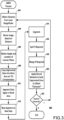
- a representative flow chart of one possible implementation of a laser-based speed gun 200 incorporating an ANPR function 300 in accordance with the principles of the present invention is shown.
- the representative ANPR process includes determining the distance to the target vehicle license plate as determined by the laser rangefinder and as computed by the processor 202 at step 302.
- the speed gun 200 then computationally resizes the image of the license plate based on the computed distance at step 304.
- the height and location of the license plate is then obtained at step 306 and the segmented data is then copied into the work area of the processor 202 along with tilt compensation information derived from, for example, the inclinometer 224 ( Fig. 2A ) as shown in step 308.
- the data is once again segmented and a new segment determined on the raw data at step 312.
- a further segment operation is performed at step 314 and the data is split, if required, at step 316 along with a merge operation at step 318 if also required.
- a neural network is applied to each segmented zone in order to obtain the particular alpha or numerical character being considered at step 320. If another character of the license plate needs to be determined at decision step 322, then the ANPR process returns to step 302 to continue the ANPR function 300.
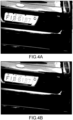
- FIGs. 4A through 4I various views of an example license plate are shown illustrative of a representative ANPR function implemented in conjunction with a speed gun in accordance with the principles of the present invention.
- a representative image of a license plate is shown.
- the technique of the present invention performs well if the width of each character in the image is approximately 10 pixels or greater.
- Fig. 4B an average 3x3 filter is applied to the image.
- this filter operation is performed by a Neon processor employing single instruction multiple data (SIMD), which employs and architecture for the ARM Cortex-A series and Cortex-R52 processors.
- SIMD single instruction multiple data
- FIG. 4C edge detection of the image is performed in the X direction only and in Fig. 4D , adjacent segments or the characters are grouped.
- Fig. 4E shows the license plate character candidates being grouped and tilt compensation being applied.
- the representative license plate image is shown in Fig. 4F with anti-aliasing having been applied and, as shown in Fig. 4G , following a rolling shutter compensation operation. Anti-aliasing is then again applied as shown in Fig. 4H and the characters of the license plate segmented (after rolling shutter compensation) in Fig. 4I .
- the ANPR function of the preceding figures may also advantageously incorporate steps such as the trimming of the license plate characters, the application of a neural network, the retrieval of data and the application of the process with respect to license plates having two rows of alpha and numeric characters.
- the technique of the present invention is also applicable to those number plates having, for example, Cyrillic, Chinese, Korean, Japanese characters or Arabic alphabet representations.
Landscapes
- Physics & Mathematics (AREA)
- Engineering & Computer Science (AREA)
- General Physics & Mathematics (AREA)
- Electromagnetism (AREA)
- Radar, Positioning & Navigation (AREA)
- Remote Sensing (AREA)
- Computer Networks & Wireless Communication (AREA)
- Traffic Control Systems (AREA)
- Optical Radar Systems And Details Thereof (AREA)
Description
- A portion of the disclosure of this patent document contains material which is subject to copyright protection. The copyright owner has no objection to the facsimile reproduction by anyone of the patent document of the patent disclosure as it appears in the United States Patent and Trademark Office patent file or records, but otherwise, reserves all copyright rights whatsoever. The following notice applies to the software and data and described below, inclusive of the drawing figures where applicable: Copyright © 2019, Laser Technology, Inc.
- The present invention relates, in general, to the field of handheld laser-based vehicle speed measurement devices and speed guns. More particularly, the present invention relates to a handheld laser-based vehicle speed measurement device incorporating an automatic number plate recognition (ANPR) function.
- Laser Technology, Inc. assignee of the present invention, has previously introduced the TruCAM® (a registered trademark of Laser Technology, Inc.) video laser-based vehicle speed measurement device which incorporates the industry's first video camera in a handheld form factor. In operation, it collects and stores a complete chain of video evidence for both speeding and tailgating violations along with a high-resolution image that identifies the vehicle make, model and license plate number. Representative of the technology embodied in the TruCAM devices is that disclosed in, for example, in
U.S. Pat. No. 7,920,251 issuing Apr. 5, 2011 for: "Integrated Still Image, Motion Video and Speed Measurement System" ;U.S. Pat. No. 8,311,343 issuing Nov. 13, 2013 for: "Vehicle Classification by Image Processing with Laser Range Finder" andU.S. Patent No. 10,146,103 issuing December 4, 2018 for: "Camera Module and Folded Optical System for Laser-Based Speed Gun" - Laser-based speed measurement devices, operate to calculate distance by measuring the time of flight of very short pulses of infrared light. That is, a measurement is made as to the time it takes one or more laser pulses to travel to a target vehicle and back with a precision time base. With knowledge of the constant speed of light, the distance the laser pulses have traveled can then be calculated. If the speed gun takes, for example, a thousand samples per second, its processor can compare the change in distance between successive samples and thereby calculate the speed of the target vehicle. By taking several hundred samples over the course of a fraction of a second or so, the accuracy can be extremely high.
- Conventional, fixed position, automatic number plate recognition (ANPR) is a technology that uses optical character recognition on images to read vehicle registration plates to create vehicle identification data. At present, it can be implemented using closed-circuit television, fixed traffic enforcement cameras, or other cameras specifically designed for the task. ANPR is used by police forces around the world for law enforcement purposes, including to check if a vehicle is currently being sought for whatever reason, registered and/or licensed. It is also used for electronic toll collection on pay-per-use roads and as a method of cataloguing the movements of traffic, for example by highways agencies.
- Automatic number plate recognition can be used to store the images captured by the cameras as well as the text from the license plate, with some configurable to store a photograph of the driver. Systems may also employ infrared lighting to allow the camera to take the picture at any time of day or night.
-
US 2004/101166 A1 describes a speed measurement system for measuring speeds of vehicles, capturing images of vehicles, and detecting violation of stop sign and traffic signal laws. The system includes a laser speed detector for determining a speed of a vehicle adjacent a stop sign. When a speed is determined, the detector generates a speed signal. The system includes a camera generally aligned with the speed detector operable to capture and store digital still images of vehicles in memory. The camera is programmed to respond to an image capture signal to generate and transmit a digital image file including a still image of the vehicle targeted by the detector. A portable processor is linked to the speed detector and the camera to first receive the speed signal, to compare the detected speed with a threshold speed, to transmit an image capture signal to the camera, and to receive the image file from the camera. - Heretofore, ANPR functionality has not been able to be implemented in a handheld speed measurement device, whether implemented in conjunction with radar or laser-based speed measurement devices. Particularly, all existing ANPR equipment utilize and assume predetermined geometries between the instrument and the vehicle license plate (inclusive of optical parameters and distances to plate) in order to properly function. Moreover, such existing products are not capable of accurately functioning when tilting of the device must be compensated for as in the operation of a handheld device such as a laser-based speed measurement device as disclosed herein.
- The invention is defined by the subject matter of the independent claim 1. Advantageous enhancements are subject to the dependent claims. embodiment of the present invention, both techniques may be employed.
- Typical low-cost cameras, such as those incorporated in "Body CAMs" and smart phones, utilize what are known as rolling shutters. Such cameras take an image line-by-line instead of the whole scene at once. On the other hand, with a conventional "wet film" a "global shutter" is employed wherein the camera shutter is mechanically opened. In contrast, modern cameras utilize an electronic shutter so a line-by-line technique is employed.
- In any event, when a vehicle (or the speed gun itself) is moving the image of the vehicle license plate is at least somewhat distorted. Consequently, the technique of the present invention incorporates rolling shutter compensation and pre-processing of the license plate image.
- As with any handheld device, power considerations are also important as most will be battery powered. Consequently, the processing algorithms are advantageously "lighter" and less computationally intensive. The principles of the present invention are readily implemented in a self-contained device such as an "off-line Body Cam" and may be coupled to a database to provide appropriate notice to a user of the speed gun when a "wanted" vehicle license plate is found through connection to a cellular network, WiFi connection or the like.
- Particularly disclosed herein is a handheld laser-based speed gun comprising a processor and laser signal transmitting and receiving sections coupled to the processor for determining a speed of a target vehicle based on changes in distance between the speed gun and the target vehicle over time. The speed gun further comprises a camera module coupled to the processor for capturing images of the target vehicle number plate and an automatic number plate recognition (ANPR) module is also coupled to the processor in operative association with said camera module.
- Also particularly disclosed herein is a method for identifying a vehicle number plate of interest with a handheld distance ranging device comprising an image sensor. The method comprises capturing an image of the vehicle number plate; compensating the captured image to account for a determined distance of the ranging device to the vehicle number plate to produce a compensated image; and determining if the compensated image resides in a database of the vehicle number plates of interest.
- The aforementioned and other features and objects of the present invention and the manner of attaining them will become more apparent and the invention itself will be best understood by reference to the following description of a preferred embodiment taken in conjunction with the accompanying drawings, wherein:
-
Fig. 1 is an isometric view of a representative laser-based speed gun incorporating a camera module and folded optical system incorporating an ANPR function; -
Figs. 2A and2B are representative functional block diagrams of a laser-based speed gun of the preceding figure in accordance with the principles of the present invention; -
Fig. 3 is a representative flow chart of one possible implementation of a laser-based speed gun incorporating an ANPR function in accordance with the principles of the present invention; and -
Figs. 4A through 4I are illustrative of a representative ANPR function implemented in conjunction with a speed gun in accordance with the principles of the present invention. - With reference now to
Fig. 1 , an isometric view of a representative laser-basedspeed gun 100 is shown incorporating a camera module and foldedoptical system 120 incorporating an ANPR function in accordance with the principles of the present invention. The laser-basedspeed gun 100 comprises ahousing 102 and associatedhandle 104 for handheld operation. Atrigger 106 is provided to initiate the transmission and reception of laser pulses toward a moving object, such as a vehicle, as well as initiate the recording of video of the object in conjunction with the camera module and foldedoptical system 120. The laser-basedspeed gun 100, as illustrated, includes adisplay 108, user input andselection elements 110 as well as targetvehicle sighting optics 112. A representative laser-based speed gun may be implemented in accordance with the disclosure of commonly ownedU.S. Patent No. 10,146,103 issuing December 4, 2018 for "Camera Module and Folded Optical System for Laser-Based Speed Gun - With reference now to
Fig. 2A , a representative functional block diagram of the laser-basedspeed gun 200 of the preceding figure in accordance with the principles of the present invention is shown. - The
exemplary speed gun 100 comprises amicroprocessor 202 or central processing unit (CPU) with an associated oscillator 204 (where required) for providing clocking signals to themicroprocessor 202. A battery andpower management section 206 supplies operating power to themicroprocessor 202 and various other speed gun subsystems (not shown) as well as the high voltage (HV)power supply 208 which provides operating voltage to a laser transmitsection 210 and associated laser diode as well as a laser receivesection 212 and associated photodiode. - The laser receive
section 212 receives a portion of the laser energy transmitted by the laser transmitsection 210 as reflected by a target vehicle to a photodiode and provides the return signals to a signal/noise (S/N)discriminator section 214 in order to separate true return pulses from any associated noise. Atiming section 216 accurately measures the time between the transmission of laser pulses from the laser transmitsection 210 and the reception of the same target vehicle reflected pulses at the laser receivesection 212 to determine, in conjunction with themicroprocessor 202, the varying distance, and hence the speed, of the particular target vehicle towards which thespeed gun 200 is aimed. - A
fire button 222 is coupled to the battery andpower management section 206 and is operable by a user of thespeed gun 200 in conjunction with themicroprocessor 202 to determine when to emit pulses toward a target vehicle from the laser transmitsection 210. - The
speed gun 200 may also incorporate a user viewable in-sight display 218 implemented in conjunction with a novel and proprietary backlighting technique which may include a view of the target vehicle in conjunction with an aiming reticle as well as information regarding the range to, and/or speed of, the target vehicle, battery condition and other information. In certain embodiments, thespeed gun 200 may also comprise a touchscreen display to allow user to provide inputs to thespeed gun 200 in conjunction with, or as an alternative to, an input/output (I/O)section 220. - The I/
O section 220 may further comprise a keypad or other means of communicating information to or from themicroprocessor 202 including wired connections such as a universal serial bus (USB) and the like as well as wireless connections such as an IEEE 802.11 (WiFi), or other wireless local area network (WLAN) transceiver; a Bluetooth transceiver or other personal area network (PAN) system for wirelessly exchanging data over short distances; and/or another near field communication (NFC) transceiver (inclusive of infrared (IR) coupling) for wirelessly coupling thespeed gun 200 to external devices or data storage elements. - As illustrated, the
speed gun 200 may further include one or more of additional input modules such as aninclinometer 224, accelerometer, 226, magnetic sensor 228 (e.g. a compass) and/orrate gyro 230. - As an exemplary utilization of a backlighting technique for LCDs and other display devices in electronic speed guns or the present invention, the
speed gun 200 is illustrated as incorporating abacklight 232. In a representative embodiment of thespeed gun 200 of the present invention, thebacklight 232 may be advantageously provided in accordance with the specification and teachings of commonly ownedU.S. Patent 9,964,805 issued on May 8, 2018 for: "Backlighting Technique for Liquid Crystal and Other Displays in Electronic Speed guns - As further illustrated, the
speed gun 200 may comprise areticle 234 interposed between the backlight and the in-sight display 218 as is more fully described in the aforementioned '805 patent. A global positioning satellite (GPS)module 236 may also form a portion of thespeed gun 200 to provide information to themicroprocessor 202 as to the specific geographic position of thespeed gun 200. In addition, and as previously noted, thespeed gun 200 may further include anNFC module 238 capable of enabling external bidirectional communication with thespeed gun 200 via Bluetooth, WiFi and the like in conjunction with a smartphone, tablet device, computer laptop etc. - In an alternative embodiment of the present invention, the
speed gun 200 may further be configured to provide an augmented reality display to a user by the additional provision of an advanced in-scope display orcamera module 240 andview screen 242. In this manner, by angularly scanning thespeed gun 200 about a target vehicle, other features and objects in the surrounding scene can be displayed in the view screen 242 (or in-sight display 218 and/or the screen of an associated smartphone, tablet device or laptop) to a user of thespeed gun 200 along with the determined distances to such additional features and objects to provide additional terrain context over and above the speed of, or distance to, the desired target vehicle. Such features and objects might be, depending on the particular application of thespeed gun 100 trees, highway overpasses, signs, buildings and the like. The in-scope display or camera module 140 is then operational to log the surrounding features and objects, and their distances determined by the laser-basedspeed gun 200 and this information displayed in a picture to a user of thespeed gun 200, whether on the speed gun itself or on the screen of any associated device. - With reference additionally now to
Fig. 2B , an additional representative portion of the functional block diagram of the laser-basedspeed gun 200 of the preceding figure is shown illustrative of an embodiment of the present invention which may further include a vibro-motor 250 and one or more audio and/orvisual indicators 252 to provide physical, haptic and audible and/or visible feedback to the user of a particular target vehicle number plate being of interest. A laser-basedspeed gun 200 in accordance with the present invention will include anANPR function block 254 as illustrated and may further include acellular telephony block 256 and/orWiFi block 258, and/or NFC or other communications medium, to bidirectionally communicate data regarding a vehicle's license plate number as well as speed and other information to/from a location and database remote from the laser-basedspeed gun 200. TheANPR function block 254 is operative in conjunction with themicroprocessor 202 and thecamera module 240 as will be more fully disclosed hereinafter. - A system comprising the laser-based
speed gun 200 may further include adatabase 260 either resident in the laser-basedspeed gun 200 itself or remotely therefrom in communication with said laser-basedspeed gun 200. Thedatabase 260 may, for example, comprise number plates of particular interest to authorities which can then be matched to the number plate of a target vehicle as determined by the ANPR functionality. This information can be added to thedatabase 260 or communicated to the operator of the laser-basedspeed gun 200 by haptic or aural and/or visual means by virtue of vibro-motor 250 and the auralvisual indicator 252. - With reference additionally now to
Fig. 3 , a representative flow chart of one possible implementation of a laser-basedspeed gun 200 incorporating anANPR function 300 in accordance with the principles of the present invention is shown. The representative ANPR process includes determining the distance to the target vehicle license plate as determined by the laser rangefinder and as computed by theprocessor 202 atstep 302. Thespeed gun 200 then computationally resizes the image of the license plate based on the computed distance atstep 304. - The height and location of the license plate is then obtained at
step 306 and the segmented data is then copied into the work area of theprocessor 202 along with tilt compensation information derived from, for example, the inclinometer 224 (Fig. 2A ) as shown instep 308. Atstep 310, the data is once again segmented and a new segment determined on the raw data atstep 312. A further segment operation is performed atstep 314 and the data is split, if required, atstep 316 along with a merge operation atstep 318 if also required. - At this point a neural network is applied to each segmented zone in order to obtain the particular alpha or numerical character being considered at
step 320. If another character of the license plate needs to be determined atdecision step 322, then the ANPR process returns to step 302 to continue theANPR function 300. - With reference now to
Figs. 4A through 4I , various views of an example license plate are shown illustrative of a representative ANPR function implemented in conjunction with a speed gun in accordance with the principles of the present invention. - With reference specifically to
Fig. 4A , a representative image of a license plate is shown. In general, the technique of the present invention performs well if the width of each character in the image is approximately 10 pixels or greater. InFig. 4B , an average 3x3 filter is applied to the image. In the TruCam2® instrument available from Laser Technology, Inc., assignee of the present invention, this filter operation is performed by a Neon processor employing single instruction multiple data (SIMD), which employs and architecture for the ARM Cortex-A series and Cortex-R52 processors. - With respect to
Fig. 4C , edge detection of the image is performed in the X direction only and inFig. 4D , adjacent segments or the characters are grouped.Fig. 4E shows the license plate character candidates being grouped and tilt compensation being applied. - The representative license plate image is shown in
Fig. 4F with anti-aliasing having been applied and, as shown inFig. 4G , following a rolling shutter compensation operation. Anti-aliasing is then again applied as shown inFig. 4H and the characters of the license plate segmented (after rolling shutter compensation) inFig. 4I . - Although not specifically illustrated, the ANPR function of the preceding figures may also advantageously incorporate steps such as the trimming of the license plate characters, the application of a neural network, the retrieval of data and the application of the process with respect to license plates having two rows of alpha and numeric characters. The technique of the present invention is also applicable to those number plates having, for example, Cyrillic, Chinese, Korean, Japanese characters or Arabic alphabet representations.
- While there have been described above the principles of the present invention in conjunction with specific apparatus, it is to be clearly understood that the foregoing description is made only by way of example and not as a limitation to the scope of the invention. Particularly, it is recognized that the teachings of the foregoing disclosure will suggest other modifications to those persons skilled in the relevant art. Such modifications may involve other features which are already known per se and which may be used instead of or in addition to features already described herein. Although claims have been formulated in this application to particular combinations of features, it should be understood that the scope of the disclosure herein also includes any novel feature or any novel combination of features disclosed either explicitly or implicitly or any generalization or modification thereof which would be apparent to persons skilled in the relevant art, whether or not such relates to the same invention as presently claimed in any claim and whether or not it mitigates any or all of the same technical problems as confronted by the present invention. The applicants hereby reserve the right to formulate new claims to such features and/or combinations of such features during the prosecution of the present application or of any further application derived therefrom.
- As used herein, the terms "comprises", "comprising", or any other variation thereof, are intended to cover a non-exclusive inclusion, such that a process, method, article, or apparatus that comprises a recitation of certain elements does not necessarily include only those elements but may include other elements not expressly recited or inherent to such process, method, article or apparatus. Although the invention has been explained in relation to its preferred embodiment(s) as mentioned above, it is to be understood that many other possible modifications and variations can be made without departing from the scope of the present invention, which is defined by the claims.
Claims (4)
- A handheld laser-based speed gun (100) comprising:a processor (202);laser signal transmitting and receiving sections (210, 212) coupled to said processor for determining a speed of a target vehicle based on changes in distance between said speed gun and said target vehicle over time;a camera module (240) coupled to said processor for capturing images of said target vehicle number plate, wherein the captured images of the target vehicle number plate comprise alphanumeric characters; andan automatic number plate recognition (ANPR) module (254) coupled to said processor in operative association with said camera module, wherein the distance between said speed gun and said target vehicle is utilized to resize the images of the license plate for input into the ANPR module.
- The speed gun (100) of claim 1 further comprising a tilt sensor in operative communication with said ANPR module (254) and said processor (202), output of said tilt sensor being utilized to compensate for said images of said target vehicle number plate being not orthogonal to the camera frame.
- The speed gun (100) of claim 1 further comprising said captured images by said camera module (240) being utilized in operative communication with said ANPR module (254) and said processor (202) to compensate for said images of said target vehicle number plate being not orthogonal to the camera frame.
- The speed gun (100) of claim 1 wherein said captured images by said camera module (240) in conjunction with said output of said tilt sensor are both utilized to compensate for said images of said target vehicle number plate being not orthogonal to the camera frame.
Applications Claiming Priority (2)
| Application Number | Priority Date | Filing Date | Title |
|---|---|---|---|
| US201862769803P | 2018-11-20 | 2018-11-20 | |
| PCT/US2019/062235 WO2020106733A1 (en) | 2018-11-20 | 2019-11-19 | Handheld laser -based vehicle speed measurement device incorporating an automatic number plate recognition (anpr) function |
Publications (3)
| Publication Number | Publication Date |
|---|---|
| EP3884478A1 EP3884478A1 (en) | 2021-09-29 |
| EP3884478A4 EP3884478A4 (en) | 2022-07-20 |
| EP3884478B1 true EP3884478B1 (en) | 2025-05-07 |
Family
ID=70726699
Family Applications (1)
| Application Number | Title | Priority Date | Filing Date |
|---|---|---|---|
| EP19886437.3A Active EP3884478B1 (en) | 2018-11-20 | 2019-11-19 | Handheld laser -based vehicle speed measurement device incorporating an automatic number plate recognition (anpr) function |
Country Status (7)
| Country | Link |
|---|---|
| US (2) | US11663910B2 (en) |
| EP (1) | EP3884478B1 (en) |
| AU (1) | AU2019383973B2 (en) |
| BR (1) | BR112021009115A2 (en) |
| CA (1) | CA3119999A1 (en) |
| WO (1) | WO2020106733A1 (en) |
| ZA (1) | ZA202103287B (en) |
Families Citing this family (1)
| Publication number | Priority date | Publication date | Assignee | Title |
|---|---|---|---|---|
| CN112836683B (en) * | 2021-03-04 | 2024-07-09 | 广东建邦计算机软件股份有限公司 | License plate recognition method, device, equipment and medium for portable camera device |
Citations (2)
| Publication number | Priority date | Publication date | Assignee | Title |
|---|---|---|---|---|
| US20100260387A1 (en) * | 2009-04-10 | 2010-10-14 | Hon Hai Precision Industry Co., Ltd. | Image capture device and subject recognition method using the same |
| US20170032666A1 (en) * | 2014-04-14 | 2017-02-02 | Licensys Australasia Pty Ltd | Vehicle Identification and/or Monitoring System |
Family Cites Families (30)
| Publication number | Priority date | Publication date | Assignee | Title |
|---|---|---|---|---|
| US4025761A (en) * | 1975-04-16 | 1977-05-24 | Schiller Industries, Inc. | Optical system for code symbol scanners |
| DE4412100C2 (en) | 1994-04-08 | 1996-02-08 | Jenoptik Technologie Gmbh | Arrangement for measuring the distance of an object and its image |
| US7133608B1 (en) | 1995-06-08 | 2006-11-07 | Minolta Co., Ltd. | Camera |
| US5717195A (en) | 1996-03-05 | 1998-02-10 | Metanetics Corporation | Imaging based slot dataform reader |
| US6392238B1 (en) | 1999-06-09 | 2002-05-21 | Jobin Yvon Inc. | UV-imager system |
| US6681195B1 (en) * | 2000-03-22 | 2004-01-20 | Laser Technology, Inc. | Compact speed measurement system with onsite digital image capture, processing, and portable display |
| US7708205B2 (en) | 2003-11-13 | 2010-05-04 | Metrologic Instruments, Inc. | Digital image capture and processing system employing multi-layer software-based system architecture permitting modification and/or extension of system features and functions by way of third party code plug-ins |
| JP2002277736A (en) | 2001-03-21 | 2002-09-25 | Olympus Optical Co Ltd | Image pickup device |
| US6696978B2 (en) | 2001-06-12 | 2004-02-24 | Koninklijke Philips Electronics N.V. | Combined laser/radar-video speed violation detector for law enforcement |
| JP2004078067A (en) | 2002-08-22 | 2004-03-11 | Fuji Photo Film Co Ltd | Lens-fitted photographic film unit and digital printer |
| US6970102B2 (en) * | 2003-05-05 | 2005-11-29 | Transol Pty Ltd | Traffic violation detection, recording and evidence processing system |
| JP2005128364A (en) | 2003-10-27 | 2005-05-19 | Canon Inc | Finder device and optical apparatus |
| US9247215B1 (en) | 2005-04-22 | 2016-01-26 | Custom Manufacturing & Engineering, Inc. | Laser sensor system |
| US20070154202A1 (en) * | 2006-01-04 | 2007-07-05 | Lee King F | Method and apparatus to facilitate correcting rolling shutter images |
| WO2007099813A1 (en) | 2006-02-27 | 2007-09-07 | Konica Minolta Opto, Inc. | Lens unit and imaging device |
| US20140369566A1 (en) | 2006-04-04 | 2014-12-18 | Cyclops Technologies, Inc. | Perimeter Image Capture and Recognition System |
| US8446467B2 (en) | 2006-05-05 | 2013-05-21 | Scott K. Tilton | Combined speed detection, video and timing apparatus |
| AT505258B1 (en) | 2007-06-11 | 2010-06-15 | Swarovski Optik Kg | ADAPTER FOR CONNECTING AN OPTICAL RECORDING DEVICE WITH AN OBSERVATORY |
| WO2009042605A1 (en) | 2007-09-24 | 2009-04-02 | Laser Technology, Inc. | Integrated still image, motion video and speed measurement system |
| US20090091821A1 (en) | 2007-10-09 | 2009-04-09 | Regan Rick R | Optical sighting device with selective laser wavelength removal |
| US8311343B2 (en) | 2009-02-12 | 2012-11-13 | Laser Technology, Inc. | Vehicle classification by image processing with laser range finder |
| JP5240328B2 (en) | 2011-08-08 | 2013-07-17 | カシオ計算機株式会社 | Imaging apparatus and program |
| US20140063261A1 (en) | 2012-08-29 | 2014-03-06 | Pocket Optics, LLC | Portable distance measuring device with a laser range finder, image sensor(s) and microdisplay(s) |
| AU2014274669A1 (en) | 2013-06-06 | 2016-01-07 | Kustom Signals, Inc. | Traffic enforcement system with time tracking and integrated video capture |
| US9392188B2 (en) | 2014-08-10 | 2016-07-12 | Corephotonics Ltd. | Zoom dual-aperture camera with folded lens |
| US10565734B2 (en) | 2015-04-15 | 2020-02-18 | Google Llc | Video capture, processing, calibration, computational fiber artifact removal, and light-field pipeline |
| US9842263B2 (en) * | 2015-11-10 | 2017-12-12 | Ford Global Technologies, Llc | Inter-vehicle authentication using visual contextual information |
| US9785855B2 (en) | 2015-12-17 | 2017-10-10 | Conduent Business Services, Llc | Coarse-to-fine cascade adaptations for license plate recognition with convolutional neural networks |
| US10146103B2 (en) | 2016-03-31 | 2018-12-04 | Laser Technology, Inc. | Camera module and folded optical system for laser-based speed gun |
| US9964805B2 (en) | 2016-08-26 | 2018-05-08 | Laser Technology, Inc. | Backlighting technique for liquid crystal and other displays in electronic instruments |
-
2019
- 2019-11-19 US US16/688,633 patent/US11663910B2/en active Active
- 2019-11-19 CA CA3119999A patent/CA3119999A1/en active Pending
- 2019-11-19 BR BR112021009115-7A patent/BR112021009115A2/en active Search and Examination
- 2019-11-19 AU AU2019383973A patent/AU2019383973B2/en active Active
- 2019-11-19 WO PCT/US2019/062235 patent/WO2020106733A1/en not_active Ceased
- 2019-11-19 EP EP19886437.3A patent/EP3884478B1/en active Active
-
2021
- 2021-05-14 ZA ZA2021/03287A patent/ZA202103287B/en unknown
-
2022
- 2022-03-16 US US17/696,624 patent/US20220208000A1/en not_active Abandoned
Patent Citations (2)
| Publication number | Priority date | Publication date | Assignee | Title |
|---|---|---|---|---|
| US20100260387A1 (en) * | 2009-04-10 | 2010-10-14 | Hon Hai Precision Industry Co., Ltd. | Image capture device and subject recognition method using the same |
| US20170032666A1 (en) * | 2014-04-14 | 2017-02-02 | Licensys Australasia Pty Ltd | Vehicle Identification and/or Monitoring System |
Also Published As
| Publication number | Publication date |
|---|---|
| CA3119999A1 (en) | 2020-05-28 |
| BR112021009115A2 (en) | 2021-08-10 |
| US20200160700A1 (en) | 2020-05-21 |
| AU2019383973B2 (en) | 2025-05-22 |
| US20220208000A1 (en) | 2022-06-30 |
| AU2019383973A1 (en) | 2021-06-03 |
| ZA202103287B (en) | 2023-10-25 |
| EP3884478A4 (en) | 2022-07-20 |
| WO2020106733A1 (en) | 2020-05-28 |
| EP3884478A1 (en) | 2021-09-29 |
| US11663910B2 (en) | 2023-05-30 |
Similar Documents
| Publication | Publication Date | Title |
|---|---|---|
| US8311343B2 (en) | Vehicle classification by image processing with laser range finder | |
| US9691277B2 (en) | Integrated still image, motion video and speed measurement system | |
| US9146316B2 (en) | Lidar measurement device for vehicular traffic surveillance and method for use of same | |
| USRE50261E1 (en) | System and method for multipurpose traffic detection and characterization | |
| US8294595B1 (en) | Speed detector for moving vehicles | |
| KR100533033B1 (en) | Position tracing system and method using digital video process technic | |
| KR101806663B1 (en) | Transfer information obseravation system integrated radar with video camera | |
| CN103852067A (en) | Method for adjusting operating parameters of Time of Flight (TOF) measurement system | |
| CA2914345A1 (en) | Traffic enforcement system with time tracking and integrated video capture | |
| US20220208000A1 (en) | Handheld laser-based vehicle speed measurement device incorporating an automatic number plate recognition (anpr) function | |
| RU120270U1 (en) | PEDESTRIAN CROSSING CONTROL COMPLEX | |
| US7333634B2 (en) | Method and apparatus for a velocity detection system using optical growth rate | |
| KR100725669B1 (en) | Driving vehicle recognition system | |
| KR100812765B1 (en) | Speeding vehicle chopper | |
| RU2539676C2 (en) | System for video recording and measurement of speed and coordinates of vehicles | |
| RU196605U1 (en) | Device for automatic monitoring of video module positioning | |
| RU134684U1 (en) | SYSTEM FOR DETECTION AND VIDEO FIXATION OF VEHICLES VIOLATING THE RULES OF PARKING, STOPPING AND PARKING | |
| KR20020020050A (en) | An overspeeding vehicle detecting device using image processing | |
| JP7694897B2 (en) | Object detection device, system, method, and program | |
| CN117671576A (en) | Imaging processing method for identifying dangerous target | |
| RU107380U1 (en) | SYSTEM OF CONTROL OF COMPLIANCE WITH RULES OF ROAD VEHICLES AND DEVICE FOR VIDEO FIXATION OF VIOLATIONS | |
| RU2658120C1 (en) | Multi-purpose multiband laser meter for vehicle transmission with video fixation | |
| US12379500B2 (en) | Laser ranging and speed measurement device incorporating on-board data storage with GPS, compass, excessive panning detection and voice recognition technology | |
| KR200212317Y1 (en) | An overspeeding vehicle detecting device using image processing | |
| KR20240170786A (en) | Apparatus and method for detecting overspeed using image processing technology |
Legal Events
| Date | Code | Title | Description |
|---|---|---|---|
| STAA | Information on the status of an ep patent application or granted ep patent |
Free format text: STATUS: THE INTERNATIONAL PUBLICATION HAS BEEN MADE |
|
| PUAI | Public reference made under article 153(3) epc to a published international application that has entered the european phase |
Free format text: ORIGINAL CODE: 0009012 |
|
| STAA | Information on the status of an ep patent application or granted ep patent |
Free format text: STATUS: REQUEST FOR EXAMINATION WAS MADE |
|
| 17P | Request for examination filed |
Effective date: 20210507 |
|
| AK | Designated contracting states |
Kind code of ref document: A1 Designated state(s): AL AT BE BG CH CY CZ DE DK EE ES FI FR GB GR HR HU IE IS IT LI LT LU LV MC MK MT NL NO PL PT RO RS SE SI SK SM TR |
|
| DAV | Request for validation of the european patent (deleted) | ||
| DAX | Request for extension of the european patent (deleted) | ||
| RIC1 | Information provided on ipc code assigned before grant |
Ipc: G01S 17/88 20060101ALI20220311BHEP Ipc: G01S 17/00 20200101ALI20220311BHEP Ipc: G08G 1/017 20060101AFI20220311BHEP |
|
| A4 | Supplementary search report drawn up and despatched |
Effective date: 20220620 |
|
| RIC1 | Information provided on ipc code assigned before grant |
Ipc: G01S 17/88 20060101ALI20220614BHEP Ipc: G01S 17/00 20200101ALI20220614BHEP Ipc: G08G 1/017 20060101AFI20220614BHEP |
|
| STAA | Information on the status of an ep patent application or granted ep patent |
Free format text: STATUS: EXAMINATION IS IN PROGRESS |
|
| 17Q | First examination report despatched |
Effective date: 20230130 |
|
| P01 | Opt-out of the competence of the unified patent court (upc) registered |
Effective date: 20230516 |
|
| GRAP | Despatch of communication of intention to grant a patent |
Free format text: ORIGINAL CODE: EPIDOSNIGR1 |
|
| STAA | Information on the status of an ep patent application or granted ep patent |
Free format text: STATUS: GRANT OF PATENT IS INTENDED |
|
| INTG | Intention to grant announced |
Effective date: 20241203 |
|
| GRAS | Grant fee paid |
Free format text: ORIGINAL CODE: EPIDOSNIGR3 |
|
| GRAA | (expected) grant |
Free format text: ORIGINAL CODE: 0009210 |
|
| STAA | Information on the status of an ep patent application or granted ep patent |
Free format text: STATUS: THE PATENT HAS BEEN GRANTED |
|
| AK | Designated contracting states |
Kind code of ref document: B1 Designated state(s): AL AT BE BG CH CY CZ DE DK EE ES FI FR GB GR HR HU IE IS IT LI LT LU LV MC MK MT NL NO PL PT RO RS SE SI SK SM TR |
|
| REG | Reference to a national code |
Ref country code: GB Ref legal event code: FG4D |
|
| REG | Reference to a national code |
Ref country code: CH Ref legal event code: EP |
|
| REG | Reference to a national code |
Ref country code: DE Ref legal event code: R096 Ref document number: 602019069787 Country of ref document: DE |
|
| REG | Reference to a national code |
Ref country code: IE Ref legal event code: FG4D |
|
| REG | Reference to a national code |
Ref country code: NL Ref legal event code: MP Effective date: 20250507 |
|
| PG25 | Lapsed in a contracting state [announced via postgrant information from national office to epo] |
Ref country code: ES Free format text: LAPSE BECAUSE OF FAILURE TO SUBMIT A TRANSLATION OF THE DESCRIPTION OR TO PAY THE FEE WITHIN THE PRESCRIBED TIME-LIMIT Effective date: 20250507 Ref country code: PT Free format text: LAPSE BECAUSE OF FAILURE TO SUBMIT A TRANSLATION OF THE DESCRIPTION OR TO PAY THE FEE WITHIN THE PRESCRIBED TIME-LIMIT Effective date: 20250908 Ref country code: FI Free format text: LAPSE BECAUSE OF FAILURE TO SUBMIT A TRANSLATION OF THE DESCRIPTION OR TO PAY THE FEE WITHIN THE PRESCRIBED TIME-LIMIT Effective date: 20250507 |
|
| REG | Reference to a national code |
Ref country code: LT Ref legal event code: MG9D |
|
| PG25 | Lapsed in a contracting state [announced via postgrant information from national office to epo] |
Ref country code: NO Free format text: LAPSE BECAUSE OF FAILURE TO SUBMIT A TRANSLATION OF THE DESCRIPTION OR TO PAY THE FEE WITHIN THE PRESCRIBED TIME-LIMIT Effective date: 20250807 Ref country code: GR Free format text: LAPSE BECAUSE OF FAILURE TO SUBMIT A TRANSLATION OF THE DESCRIPTION OR TO PAY THE FEE WITHIN THE PRESCRIBED TIME-LIMIT Effective date: 20250808 |
|
| PG25 | Lapsed in a contracting state [announced via postgrant information from national office to epo] |
Ref country code: PL Free format text: LAPSE BECAUSE OF FAILURE TO SUBMIT A TRANSLATION OF THE DESCRIPTION OR TO PAY THE FEE WITHIN THE PRESCRIBED TIME-LIMIT Effective date: 20250507 Ref country code: NL Free format text: LAPSE BECAUSE OF FAILURE TO SUBMIT A TRANSLATION OF THE DESCRIPTION OR TO PAY THE FEE WITHIN THE PRESCRIBED TIME-LIMIT Effective date: 20250507 |
|
| REG | Reference to a national code |
Ref country code: AT Ref legal event code: MK05 Ref document number: 1793375 Country of ref document: AT Kind code of ref document: T Effective date: 20250507 |
|
| PG25 | Lapsed in a contracting state [announced via postgrant information from national office to epo] |
Ref country code: BG Free format text: LAPSE BECAUSE OF FAILURE TO SUBMIT A TRANSLATION OF THE DESCRIPTION OR TO PAY THE FEE WITHIN THE PRESCRIBED TIME-LIMIT Effective date: 20250507 |
|
| PG25 | Lapsed in a contracting state [announced via postgrant information from national office to epo] |
Ref country code: HR Free format text: LAPSE BECAUSE OF FAILURE TO SUBMIT A TRANSLATION OF THE DESCRIPTION OR TO PAY THE FEE WITHIN THE PRESCRIBED TIME-LIMIT Effective date: 20250507 |
|
| PG25 | Lapsed in a contracting state [announced via postgrant information from national office to epo] |
Ref country code: AT Free format text: LAPSE BECAUSE OF FAILURE TO SUBMIT A TRANSLATION OF THE DESCRIPTION OR TO PAY THE FEE WITHIN THE PRESCRIBED TIME-LIMIT Effective date: 20250507 |
|
| PG25 | Lapsed in a contracting state [announced via postgrant information from national office to epo] |
Ref country code: RS Free format text: LAPSE BECAUSE OF FAILURE TO SUBMIT A TRANSLATION OF THE DESCRIPTION OR TO PAY THE FEE WITHIN THE PRESCRIBED TIME-LIMIT Effective date: 20250807 |
|
| PG25 | Lapsed in a contracting state [announced via postgrant information from national office to epo] |
Ref country code: IS Free format text: LAPSE BECAUSE OF FAILURE TO SUBMIT A TRANSLATION OF THE DESCRIPTION OR TO PAY THE FEE WITHIN THE PRESCRIBED TIME-LIMIT Effective date: 20250907 |
|
| PG25 | Lapsed in a contracting state [announced via postgrant information from national office to epo] |
Ref country code: LV Free format text: LAPSE BECAUSE OF FAILURE TO SUBMIT A TRANSLATION OF THE DESCRIPTION OR TO PAY THE FEE WITHIN THE PRESCRIBED TIME-LIMIT Effective date: 20250507 |
|
| PGFP | Annual fee paid to national office [announced via postgrant information from national office to epo] |
Ref country code: DE Payment date: 20251114 Year of fee payment: 7 |
|
| PGFP | Annual fee paid to national office [announced via postgrant information from national office to epo] |
Ref country code: GB Payment date: 20251009 Year of fee payment: 7 |
|
| PG25 | Lapsed in a contracting state [announced via postgrant information from national office to epo] |
Ref country code: SM Free format text: LAPSE BECAUSE OF FAILURE TO SUBMIT A TRANSLATION OF THE DESCRIPTION OR TO PAY THE FEE WITHIN THE PRESCRIBED TIME-LIMIT Effective date: 20250507 Ref country code: DK Free format text: LAPSE BECAUSE OF FAILURE TO SUBMIT A TRANSLATION OF THE DESCRIPTION OR TO PAY THE FEE WITHIN THE PRESCRIBED TIME-LIMIT Effective date: 20250507 |
|
| PGFP | Annual fee paid to national office [announced via postgrant information from national office to epo] |
Ref country code: FR Payment date: 20251113 Year of fee payment: 7 |
|
| PG25 | Lapsed in a contracting state [announced via postgrant information from national office to epo] |
Ref country code: CZ Free format text: LAPSE BECAUSE OF FAILURE TO SUBMIT A TRANSLATION OF THE DESCRIPTION OR TO PAY THE FEE WITHIN THE PRESCRIBED TIME-LIMIT Effective date: 20250507 |
|
| PG25 | Lapsed in a contracting state [announced via postgrant information from national office to epo] |
Ref country code: EE Free format text: LAPSE BECAUSE OF FAILURE TO SUBMIT A TRANSLATION OF THE DESCRIPTION OR TO PAY THE FEE WITHIN THE PRESCRIBED TIME-LIMIT Effective date: 20250507 |
|
| PG25 | Lapsed in a contracting state [announced via postgrant information from national office to epo] |
Ref country code: RO Free format text: LAPSE BECAUSE OF FAILURE TO SUBMIT A TRANSLATION OF THE DESCRIPTION OR TO PAY THE FEE WITHIN THE PRESCRIBED TIME-LIMIT Effective date: 20250507 Ref country code: SK Free format text: LAPSE BECAUSE OF FAILURE TO SUBMIT A TRANSLATION OF THE DESCRIPTION OR TO PAY THE FEE WITHIN THE PRESCRIBED TIME-LIMIT Effective date: 20250507 |
|
| PG25 | Lapsed in a contracting state [announced via postgrant information from national office to epo] |
Ref country code: IT Free format text: LAPSE BECAUSE OF FAILURE TO SUBMIT A TRANSLATION OF THE DESCRIPTION OR TO PAY THE FEE WITHIN THE PRESCRIBED TIME-LIMIT Effective date: 20250507 |
|
| REG | Reference to a national code |
Ref country code: DE Ref legal event code: R097 Ref document number: 602019069787 Country of ref document: DE |
|
| PLBE | No opposition filed within time limit |
Free format text: ORIGINAL CODE: 0009261 |
|
| STAA | Information on the status of an ep patent application or granted ep patent |
Free format text: STATUS: NO OPPOSITION FILED WITHIN TIME LIMIT |
|
| REG | Reference to a national code |
Ref country code: CH Ref legal event code: L10 Free format text: ST27 STATUS EVENT CODE: U-0-0-L10-L00 (AS PROVIDED BY THE NATIONAL OFFICE) Effective date: 20260318 |
|
| 26N | No opposition filed |
Effective date: 20260210 |