EP3884477B1 - Smoke detector - Google Patents
Smoke detector Download PDFInfo
- Publication number
- EP3884477B1 EP3884477B1 EP19802412.7A EP19802412A EP3884477B1 EP 3884477 B1 EP3884477 B1 EP 3884477B1 EP 19802412 A EP19802412 A EP 19802412A EP 3884477 B1 EP3884477 B1 EP 3884477B1
- Authority
- EP
- European Patent Office
- Prior art keywords
- light
- light emitter
- sensing chamber
- baffle
- light receiver
- Prior art date
- Legal status (The legal status is an assumption and is not a legal conclusion. Google has not performed a legal analysis and makes no representation as to the accuracy of the status listed.)
- Active
Links
Images

Classifications
-
- G—PHYSICS
- G08—SIGNALLING
- G08B—SIGNALLING SYSTEMS, e.g. PERSONAL CALLING SYSTEMS; ORDER TELEGRAPHS; ALARM SYSTEMS
- G08B17/00—Fire alarms; Alarms responsive to explosion
- G08B17/10—Actuation by presence of smoke or gases, e.g. automatic alarm devices for analysing flowing fluid materials by the use of optical means
- G08B17/103—Actuation by presence of smoke or gases, e.g. automatic alarm devices for analysing flowing fluid materials by the use of optical means using a light emitting and receiving device
- G08B17/107—Actuation by presence of smoke or gases, e.g. automatic alarm devices for analysing flowing fluid materials by the use of optical means using a light emitting and receiving device for detecting light-scattering due to smoke
-
- G—PHYSICS
- G08—SIGNALLING
- G08B—SIGNALLING SYSTEMS, e.g. PERSONAL CALLING SYSTEMS; ORDER TELEGRAPHS; ALARM SYSTEMS
- G08B17/00—Fire alarms; Alarms responsive to explosion
- G08B17/10—Actuation by presence of smoke or gases, e.g. automatic alarm devices for analysing flowing fluid materials by the use of optical means
- G08B17/11—Actuation by presence of smoke or gases, e.g. automatic alarm devices for analysing flowing fluid materials by the use of optical means using an ionisation chamber for detecting smoke or gas
- G08B17/113—Constructional details
-
- G—PHYSICS
- G08—SIGNALLING
- G08B—SIGNALLING SYSTEMS, e.g. PERSONAL CALLING SYSTEMS; ORDER TELEGRAPHS; ALARM SYSTEMS
- G08B29/00—Checking or monitoring of signalling or alarm systems; Prevention or correction of operating errors, e.g. preventing unauthorised operation
- G08B29/02—Monitoring continuously signalling or alarm systems
- G08B29/04—Monitoring of the detection circuits
-
- G—PHYSICS
- G08—SIGNALLING
- G08B—SIGNALLING SYSTEMS, e.g. PERSONAL CALLING SYSTEMS; ORDER TELEGRAPHS; ALARM SYSTEMS
- G08B29/00—Checking or monitoring of signalling or alarm systems; Prevention or correction of operating errors, e.g. preventing unauthorised operation
- G08B29/18—Prevention or correction of operating errors
Definitions
- the present disclosure relates to the field of fire safety, and in particular to a smoke detector for detecting a fire situation.
- Smoke detectors also known as smoke-sensitive fire detectors or smoke-sensing detectors, are commonly used in buildings to detect smoke generated in a fire and then send a warning signal.
- the smoke detector typically includes a sensing chamber in which a light emitter, a light receiver and a sensing area are included. When the smoke reaches a certain concentration in the sensing area, light emitted by the light emitter is scattered to the light receiver at an intensity that reaches a critical value, thereby generating a signal and sending an alarm.
- the cost of a smoke detector depends on the size of the sensing chamber thereof. As the size of the sensing chamber decreases, a distance between a side wall of the sensing chamber and the light emitter will decrease, resulting in stronger background light which may include a scattered portion of the light emitted by the light emitter and a light refracted or reflected by the wall of the sensing chamber. Such background light as a base noise may affect the normal operation of the smoke detector.
- JP 2008 310732 A discloses a scattered-light type smoke sensor according to the preamble of claim 1, wherein any detrimental effect of vibration from an alarm sound generator on the sensitivity of the smoke detector is minimized by the configuration of vent holes on the device.
- a light shielding wall is provided in the vicinity of a smoke sensing region to prevent light emitted from a light emitting unit from directly entering a light receiving unit.
- US 2017/046935 A1 discloses an optical smoke detection unit, e.g., for a smoke detector, that may include first and second light-emitting diodes for emitting monochromatic, dichromatic or polychromatic light, an optical receiver for smoke detection, and a control unit that controls the light-emitting diodes and evaluates a receive signal output by the optical receiver for fire parameters.
- the light-emitting diodes may be optically coupled together such that at least one of the light-emitting diodes illuminates the other.
- CN 206946654 U discloses a smoke detector labyrinth structure characterized by comprising two transmitting devices and a receiving device.
- An object of the present disclosure is to solve or at least alleviate the problems in the prior art.
- a smoke detector which includes:
- some of the sub-baffles extend toward the radial direction of the first light emitter.
- the branch portion is divergent in cross-section.
- the sensing chamber is cylindrical.
- some of the sub-baffles extend toward the radial direction of the first light emitter, and some of the sub-baffles extend toward the radial direction of the second light emitter.
- the sensing chamber includes an opening, a sidewall and a bottom wall, and the sidewall of the sensing chamber is toothed.
- the sensing chamber is configured to be formed by assembling a smoke guiding cover, a labyrinth body and a labyrinth base.
- the first baffle is fixed to the labyrinth base.
- the labyrinth base defines a light emitter holder and a light receiver holder, and the first light emitter and the first light receiver are respectively located in the light emitter holder and the light receiver holder, wherein pins of the first light emitter and the first light receiver are connected to the circuit board after passing through the labyrinth base, and the labyrinth body defines a light emitter cover and a light receiver cover; when the labyrinth body and the labyrinth base are assembled together, the first light emitter is fixed between the light emitter holder and the light emitter cover, and the first light receiver is fixed between the light receiver holder and the light receiver cover.
- the smoke detector according to the present disclosure has a simple structure, effectively weakens a background light in the sensing chamber, and ensures a normal operation of the smoke detector especially in a case where a volume of the sensing chamber is small.
- orientation terms as upper, lower, left, right, front, rear, front side, back side, top, bottom or the like that are mentioned or may be mentioned in this description are defined with respect to the configurations shown in the individual drawings. They are relative concepts and thus possibly vary according to their different locations and different usage states. Therefore, these or other orientation terms shall not be interpreted as limiting terms.
- FIG. 1 an exploded view of a smoke detector according to an embodiment of the present disclosure is shown.
- the smoke detector may include:
- This type of smoke detector operates following this principle: when smoke has not yet entered the sensing chamber, the light receiver receives only a small amount of background light (also referred to as base noise), which may be a scattered light of the light emitted by the light emitter, or a reflected light from an inner wall of the sensing chamber.
- background light also referred to as base noise
- the light emitted by the light emitter will be refracted by the smoke to the light receiver, causing the intensity of light received by the light receiver to increase to a critical value.
- the light receiver may be a photosensitive diode, which sends a signal when the intensity of light increases to the critical value, so that an alarm system or the like may be activated.
- the smoke detector according to the embodiment of the present disclosure provides the following structure to attenuate background light. Specifically, referring to FIGS. 2, 3 and 4 , the smoke detector according to the embodiment of the present disclosure further includes a first baffle 42 in the sensing chamber.
- the first baffle 42 is disposed adjacent to the first light emitter 81 located in a light emitter holder 47, and the first baffle 42 includes a baffle body 421 extending from the periphery of the sensing chamber toward the middle portion, and a branch portion 422 extending from the baffle body 421, the branch portion 422 including a plurality of sub-baffles 4221, 4222, 4223 and 4224 branching off the baffle body 421.
- the branch portion 422 may be divergent in cross-section, similar to the shape of a hand, including four sub-baffles 4221, 4222, 4223 and 4224.
- the branches 422 may have other shapes and may have different numbers of sub-baffles, such as two, three, or five, and the like.
- the unique structure of the first baffle 42 effectively weakens a scattered portion of the light emitted from the light emitter 81 and a reflected light from the side wall, thereby effectively reducing the background light in the sensing chamber.
- some of the sub-baffles are tilted or referred as deflected, or referred to as extending toward the radial direction of the first light emitter 81.
- the sub-baffles 4223, 4224 extend toward the radial direction of the first light emitter 81, and the sub-baffle 4221 extend toward the radial direction of the second light emitter 82, so that scattered portions of lights emitted by the first light emitter 81 and the second light emitter 82 are effectively blocked.
- the sub-baffles 4221, 4222, 4223, 4224 will not block the main light path, and thus will not affect a normal operation of the smoke detector.
- the sensing chamber may include an opening, a side wall, and a bottom wall.
- the opening of the sensing chamber is constituted by an smoke inlet 61 of a smoke guiding cover 6,
- the side wall of the sensing chamber is constituted by a side wall 51 of the labyrinth body 5, and the bottom wall of the sensing chamber is constituted by a bottom wall 41 of the labyrinth base 4.
- the sensing chamber is substantially cylindrical, and in alternative embodiments, the sensing chamber may have other suitable shapes.
- the side wall of the sensing chamber i.e., the side wall 51 of the labyrinth body 5
- the side wall of the sensing chamber i.e., the side wall 51 of the labyrinth body 5
- the first baffle 42 and optional a second baffle 43 and a third baffle 44 are each fixed to the labyrinth base 4.
- the baffles may also extend out from the side wall of the labyrinth body or the smoke guiding cover.
- the labyrinth base 4 defines light emitter holders 47, 48 and a light receiver holder 49, wherein the first light emitter 81, the second light emitter 82, and the first light receiver 91 are located in the light emitter holders 47, 48 and the light receiver holder 49 respectively. Pins of the first light emitter 81, the second light emitter 82 and the first light receiver 91 are connected to the circuit board 3 after passing through the labyrinth base 4.
- the labyrinth body 5 defines light emitter covers 57, 58 and a light receiver cover 59.
- the first light emitter 81 is fixed between the light emitter holder 47 and the light emitter cover 57
- the second light emitter 82 is fixed between the light emitter holder 48 and the light emitter cover 58
- the first light receiver 91 is fixed between the light receiver holder 49 and the light receiver cover 59.
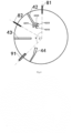
- the first light emitter 81 and the first light receiver 91 are arranged at a central angle b between 90° and 180°, a second light emitter 82 is disposed in the sensing chamber, and the second light emitter 82 is located between the first light emitter 81 and the first light receiver 91 and spaced apart from the first light receiver 91 by a central angle a of less than 90°; wherein the first baffle 42 is located between the first light emitter 81 and the second light emitter 82, part of the sub-baffles 4223, 4224 extend toward the radial direction of the first light emitter 81, and part of the sub-baffles 4221 extend toward the radial direction of the second light emitter 82.
- a second baffle 43 extending from the periphery of the sensing chamber toward the middle portion is further disposed between the second light emitter 82 and the first light receiver 91.
- the second baffle 43 blocks part of the background light.
- a third baffle 44 is further disposed at the outer side of the first light receiver 91, and an inner end (the end near the center) of the third baffle 44 extends toward the radial direction of the first light receiver 91.
- the third baffle 44 further weakens the background light that may be incident on the first light receiver 91.
Landscapes
- Physics & Mathematics (AREA)
- General Physics & Mathematics (AREA)
- Chemical & Material Sciences (AREA)
- Analytical Chemistry (AREA)
- Business, Economics & Management (AREA)
- Emergency Management (AREA)
- Engineering & Computer Science (AREA)
- Computer Security & Cryptography (AREA)
- Fire-Detection Mechanisms (AREA)
Description
- The present disclosure relates to the field of fire safety, and in particular to a smoke detector for detecting a fire situation.
- Smoke detectors, also known as smoke-sensitive fire detectors or smoke-sensing detectors, are commonly used in buildings to detect smoke generated in a fire and then send a warning signal. The smoke detector typically includes a sensing chamber in which a light emitter, a light receiver and a sensing area are included. When the smoke reaches a certain concentration in the sensing area, light emitted by the light emitter is scattered to the light receiver at an intensity that reaches a critical value, thereby generating a signal and sending an alarm.
- The cost of a smoke detector depends on the size of the sensing chamber thereof. As the size of the sensing chamber decreases, a distance between a side wall of the sensing chamber and the light emitter will decrease, resulting in stronger background light which may include a scattered portion of the light emitted by the light emitter and a light refracted or reflected by the wall of the sensing chamber. Such background light as a base noise may affect the normal operation of the smoke detector.
-
JP 2008 310732 A -
US 2017/046935 A1 discloses an optical smoke detection unit, e.g., for a smoke detector, that may include first and second light-emitting diodes for emitting monochromatic, dichromatic or polychromatic light, an optical receiver for smoke detection, and a control unit that controls the light-emitting diodes and evaluates a receive signal output by the optical receiver for fire parameters. The light-emitting diodes may be optically coupled together such that at least one of the light-emitting diodes illuminates the other. -
CN 206946654 U discloses a smoke detector labyrinth structure characterized by comprising two transmitting devices and a receiving device. - An object of the present disclosure is to solve or at least alleviate the problems in the prior art.
- According to some aspects, a smoke detector is provided, which includes:
- a housing;
- a sensing chamber in the housing, wherein in the sensing chamber, a first light emitter and a first light receiver are disposed at the periphery of the sensing chamber and facing a middle portion of the sensing chamber, the first light emitter and the first light receiver being arranged at a central angle between 90° and 180°;
- a first baffle in the sensing chamber, the first baffle being disposed adjacent to the first light emitter and including a baffle body and a branch portion, the baffle body extending from the periphery of the sensing chamber toward the middle portion, and the branch portion including a plurality of sub-baffles branching off the baffle body;
- a second light emitter disposed in the sensing chamber, the second light emitter being located between the first light emitter and the first light receiver and spaced apart from the first light receiver by a central angle of less than 90°, wherein the first baffle is located between the first light emitter and the second light emitter;
- a second baffle extending from the periphery of the sensing chamber toward the middle portion and is disposed between the second light emitter (82) and the first light receiver (91),
- wherein the second baffle blocks part of a background light comprising a scattered portion of light emitted by the second light emitter that would otherwise be incident on the first light receiver;
- a third baffle disposed at the outer side of the first light receiver, an inner end of the third baffle extending toward the radial direction of the first light receiver; and
- a circuit board electrically connected to the first light emitter and the first light receiver respectively.
- Optionally, in the smoke detector, some of the sub-baffles extend toward the radial direction of the first light emitter.
- Optionally, in the smoke detector, the branch portion is divergent in cross-section.
- Optionally, in the smoke detector, the sensing chamber is cylindrical.
- Optionally, in the smoke detector, some of the sub-baffles extend toward the radial direction of the first light emitter, and some of the sub-baffles extend toward the radial direction of the second light emitter.
- Optionally, in the smoke detector, the sensing chamber includes an opening, a sidewall and a bottom wall, and the sidewall of the sensing chamber is toothed.
- Optionally, in the smoke detector, the sensing chamber is configured to be formed by assembling a smoke guiding cover, a labyrinth body and a labyrinth base.
- Optionally, in the smoke detector, the first baffle is fixed to the labyrinth base.
- Optionally, in the smoke detector, the labyrinth base defines a light emitter holder and a light receiver holder, and the first light emitter and the first light receiver are respectively located in the light emitter holder and the light receiver holder, wherein pins of the first light emitter and the first light receiver are connected to the circuit board after passing through the labyrinth base, and the labyrinth body defines a light emitter cover and a light receiver cover; when the labyrinth body and the labyrinth base are assembled together, the first light emitter is fixed between the light emitter holder and the light emitter cover, and the first light receiver is fixed between the light receiver holder and the light receiver cover.
- The smoke detector according to the present disclosure has a simple structure, effectively weakens a background light in the sensing chamber, and ensures a normal operation of the smoke detector especially in a case where a volume of the sensing chamber is small.
- The contents of the present disclosure will become more easily understood with reference to the accompanying drawings. Those skilled in the art can readily appreciate that the drawings are for illustrative purposes only, instead of being intended to limit the scope of protection of the present disclosure. In addition, similar numbers in the drawings are used to indicate similar parts, wherein:
-
FIG. 1 shows an exploded view of a smoke detector according to an embodiment of the present disclosure; -
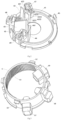
FIG. 2 shows a perspective view of a labyrinth base in a smoke detector according to an embodiment of the present disclosure; -
FIG. 3 shows a perspective view of a labyrinth body in a smoke detector according to an embodiment of the present disclosure; and -
FIG. 4 shows an arrangement view of a sensing chamber of a smoke detector according to an embodiment of the present disclosure; - It will be readily understood that, based on the technical solutions of the present disclosure, those skilled in the art can propose various alternative embodiments and implementations without departing from the scope of the present invention as defined by the claims. Therefore, the following detailed description and the accompanying drawings are merely exemplary description of the technical solutions of the present disclosure, which shall not be deemed as the whole of the present disclosure or as limiting or restricting the technical solutions of the present disclosure.
- Such orientation terms as upper, lower, left, right, front, rear, front side, back side, top, bottom or the like that are mentioned or may be mentioned in this description are defined with respect to the configurations shown in the individual drawings. They are relative concepts and thus possibly vary according to their different locations and different usage states. Therefore, these or other orientation terms shall not be interpreted as limiting terms.
- Referring first to
FIG. 1 , an exploded view of a smoke detector according to an embodiment of the present disclosure is shown. - In some embodiments, the smoke detector may include:
- a mounting base 1 configured to fix the smoke detector to a wall surface, such as a ceiling;
- a lower housing 2 and an upper housing 7, wherein the lower housing 2 and the upper housing 7 can be connected together to form an outer shell of the smoke detector, in which a sensing chamber is located, and the upper housing 7 may have a
smoke inlet 71 to allow smoke to enter the sensing chamber of the smoke detector; - the sensing chamber, wherein in the present embodiment, the sensing chamber may be composed of a smoke guiding cover 6, a labyrinth body 5 and a labyrinth base 4. The smoke guiding cover 6 may have a smoke inlet 61 to direct the smoke to a sensing area in the middle portion of the sensing chamber. A
first light emitter 81, an optionalsecond light emitter 82, and afirst light receiver 91 are disposed in the sensing chamber. Thefirst light emitter 81 and thesecond light emitter 82 may be, for example, an IRLED, and thefirst light receiver 91 may be, for example, a photosensitive diode. Thefirst light receiver 91 may be provided with ashield cover 90 to avoid interference. Thefirst light emitter 81, thesecond light emitter 82 and thefirst light receiver 91 are disposed at the periphery of the sensing chamber and facing the sensing area in the middle portion of the sensing chamber; and - a circuit board 3, which is located outside the sensing chamber, such as under the labyrinth base 4 and electrically coupled with the
first light emitter 81, thesecond light emitter 82 and/or thefirst light receiver 91. For example, the circuit board 3 supplies power to thefirst light emitter 81 and thesecond light emitter 82 and receives a signal from thefirst light receiver 91. - This type of smoke detector operates following this principle: when smoke has not yet entered the sensing chamber, the light receiver receives only a small amount of background light (also referred to as base noise), which may be a scattered light of the light emitted by the light emitter, or a reflected light from an inner wall of the sensing chamber. When the smoke enters the sensing area of the sensing chamber, the light emitted by the light emitter will be refracted by the smoke to the light receiver, causing the intensity of light received by the light receiver to increase to a critical value. For example, the light receiver may be a photosensitive diode, which sends a signal when the intensity of light increases to the critical value, so that an alarm system or the like may be activated.
- As described in the background art, as the volume of the sensing chamber becomes smaller, the background light or base noise in the sensing chamber will increase, thus affecting a normal operation of the smoke detector. The smoke detector according to the embodiment of the present disclosure provides the following structure to attenuate background light. Specifically, referring to
FIGS. 2, 3 and4 , the smoke detector according to the embodiment of the present disclosure further includes afirst baffle 42 in the sensing chamber. Thefirst baffle 42 is disposed adjacent to thefirst light emitter 81 located in a light emitter holder 47, and thefirst baffle 42 includes a baffle body 421 extending from the periphery of the sensing chamber toward the middle portion, and a branch portion 422 extending from the baffle body 421, the branch portion 422 including a plurality of sub-baffles 4221, 4222, 4223 and 4224 branching off the baffle body 421. In the illustrated embodiment, the branch portion 422 may be divergent in cross-section, similar to the shape of a hand, including foursub-baffles first baffle 42 effectively weakens a scattered portion of the light emitted from thelight emitter 81 and a reflected light from the side wall, thereby effectively reducing the background light in the sensing chamber. - In some embodiments, some of the sub-baffles are tilted or referred as deflected, or referred to as extending toward the radial direction of the
first light emitter 81. In the embodiment shown inFIGS. 2 to 4 , the sub-baffles 4223, 4224 extend toward the radial direction of thefirst light emitter 81, and the sub-baffle 4221 extend toward the radial direction of thesecond light emitter 82, so that scattered portions of lights emitted by thefirst light emitter 81 and thesecond light emitter 82 are effectively blocked. On the other hand, the sub-baffles 4221, 4222, 4223, 4224 will not block the main light path, and thus will not affect a normal operation of the smoke detector. - Referring to
FIGS. 2 and 3 , in some embodiments, the sensing chamber may include an opening, a side wall, and a bottom wall. In the illustrated embodiment, the opening of the sensing chamber is constituted by an smoke inlet 61 of a smoke guiding cover 6, the side wall of the sensing chamber is constituted by a side wall 51 of the labyrinth body 5, and the bottom wall of the sensing chamber is constituted by a bottom wall 41 of the labyrinth base 4. In some embodiments, the sensing chamber is substantially cylindrical, and in alternative embodiments, the sensing chamber may have other suitable shapes. In some embodiments, the side wall of the sensing chamber, i.e., the side wall 51 of the labyrinth body 5, is toothed to effectively suppress reflection of light by the side wall, thereby further weakening the background light. In some embodiments, as shown, thefirst baffle 42 and optional asecond baffle 43 and athird baffle 44 are each fixed to the labyrinth base 4. Alternatively, the baffles may also extend out from the side wall of the labyrinth body or the smoke guiding cover. In some embodiments, the labyrinth base 4 defines light emitter holders 47, 48 and a light receiver holder 49, wherein thefirst light emitter 81, thesecond light emitter 82, and thefirst light receiver 91 are located in the light emitter holders 47, 48 and the light receiver holder 49 respectively. Pins of thefirst light emitter 81, thesecond light emitter 82 and thefirst light receiver 91 are connected to the circuit board 3 after passing through the labyrinth base 4. The labyrinth body 5 defines light emitter covers 57, 58 and a light receiver cover 59. After the labyrinth body 5 and the labyrinth base 4 are assembled together, thefirst light emitter 81 is fixed between the light emitter holder 47 and thelight emitter cover 57, thesecond light emitter 82 is fixed between the light emitter holder 48 and the light emitter cover 58, and thefirst light receiver 91 is fixed between the light receiver holder 49 and the light receiver cover 59. - Referring specifically to
FIG. 4 , in this embodiment, thefirst light emitter 81 and thefirst light receiver 91 are arranged at a central angle b between 90° and 180°, asecond light emitter 82 is disposed in the sensing chamber, and thesecond light emitter 82 is located between thefirst light emitter 81 and thefirst light receiver 91 and spaced apart from thefirst light receiver 91 by a central angle a of less than 90°; wherein thefirst baffle 42 is located between thefirst light emitter 81 and thesecond light emitter 82, part of the sub-baffles 4223, 4224 extend toward the radial direction of thefirst light emitter 81, and part of the sub-baffles 4221 extend toward the radial direction of thesecond light emitter 82. Asecond baffle 43 extending from the periphery of the sensing chamber toward the middle portion is further disposed between thesecond light emitter 82 and thefirst light receiver 91. Thesecond baffle 43 blocks part of the background light. Athird baffle 44 is further disposed at the outer side of thefirst light receiver 91, and an inner end (the end near the center) of thethird baffle 44 extends toward the radial direction of thefirst light receiver 91. Thethird baffle 44 further weakens the background light that may be incident on thefirst light receiver 91. - The specific embodiments described above are merely for describing the principle of the present disclosure more clearly, and various components are clearly illustrated or depicted to make it easier to understand the principle of the present disclosure. Those skilled in the art can readily make various modifications or changes to the present disclosure without departing from the scope of the present disclosure. It should be understood that these modifications or changes should be included within the scope of protection of the present disclosure.
Claims (9)
- A smoke detector, comprising:a housing (2, 7);a sensing chamber (4, 5, 6) in the housing, wherein in the sensing chamber, a first light emitter (81) and a first light receiver (91) are disposed at the periphery of the sensing chamber and facing a middle portion of the sensing chamber, the first light emitter (81) and the first light receiver (91) being arranged at a central angle between 90° and 180°;a first baffle (42) in the sensing chamber, the first baffle being disposed adjacent to the first light emitter and including a baffle body (421) and a branch portion (422), the baffle body extending from the periphery of the sensing chamber toward the middle portion, and the branch portion including a plurality of sub-baffles (4221, 4222, 4223, 4224) branching off the baffle body; anda circuit board (3) electrically connected to the first light emitter (81) and the first light receiver (91) respectively;characterized in that the smoke detector further comprises:a second light emitter (82) disposed in the sensing chamber (4, 5, 6), the second light emitter being located between the first light emitter and the first light receiver and spaced apart from the first light receiver by a central angle of less than 90°, wherein the first baffle (42) is located between the first light emitter and the second light emitter;a second baffle (43) extending from the periphery of the sensing chamber toward the middle portion and disposed between the second light emitter (82) and the first light receiver (91), wherein the second baffle blocks part of a background light comprising a scattered portion of light emitted by the second light emitter that would otherwise be incident on the first light receiver; anda third baffle (44) disposed at the outer side of the first light receiver (91), an inner end of the third baffle extending toward the radial direction of the first light receiver.
- The smoke detector according to claim 1, wherein some of the sub-baffles (4223, 4224) extend toward the radial direction of the first light emitter (81).
- The smoke detector according to claim 1, wherein the branch portion (422) is divergent in cross-section.
- The smoke detector according to claim 1, wherein the sensing chamber (4, 5, 6) is cylindrical.
- The smoke detector according to claim 1, wherein some of the sub-baffles (4223, 4224) extend toward the radial direction of the first light emitter (81), and some of the sub-baffles (4221) extend toward the radial direction of the second light emitter (82).
- The smoke detector according to claim 1, wherein the sensing chamber (4, 5, 6) comprises an opening (61), a sidewall (51) and a bottom wall (41), and the sidewall of the sensing chamber is toothed.
- The smoke detector according to claim 1, wherein the sensing chamber is configured to be formed by assembling a smoke guiding cover (6), a labyrinth body (5) and a labyrinth base (4).
- The smoke detector according to claim 7, wherein the first baffle (42) is fixed to the labyrinth base (4).
- The smoke detector according to claim 7, wherein the labyrinth base (4) defines a light emitter holder (47, 48) and a light receiver holder (49), and the first light emitter (81) and the first light receiver (91) are respectively located in the light emitter holder and the light receiver holder, wherein pins of the first light emitter and the first light receiver are connected to the circuit board (3) after passing through the labyrinth base (4), and the labyrinth body (5) defines a light emitter cover (57, 58) and a light receiver cover (59); when the labyrinth body and the labyrinth base are assembled together, the first light emitter (81) is fixed between the light emitter holder (47) and the light emitter cover (57), and the first light receiver (91) is fixed between the light receiver holder (49) and the light receiver cover (59).
Priority Applications (1)
| Application Number | Priority Date | Filing Date | Title |
|---|---|---|---|
| EP25152389.0A EP4535324A3 (en) | 2018-11-20 | 2019-10-23 | Smoke detector |
Applications Claiming Priority (2)
| Application Number | Priority Date | Filing Date | Title |
|---|---|---|---|
| CN201811383578.4A CN111199628A (en) | 2018-11-20 | 2018-11-20 | Smoke detector |
| PCT/US2019/057538 WO2020106398A1 (en) | 2018-11-20 | 2019-10-23 | Smoke detector |
Related Child Applications (1)
| Application Number | Title | Priority Date | Filing Date |
|---|---|---|---|
| EP25152389.0A Division EP4535324A3 (en) | 2018-11-20 | 2019-10-23 | Smoke detector |
Publications (2)
| Publication Number | Publication Date |
|---|---|
| EP3884477A1 EP3884477A1 (en) | 2021-09-29 |
| EP3884477B1 true EP3884477B1 (en) | 2025-01-22 |
Family
ID=68542811
Family Applications (2)
| Application Number | Title | Priority Date | Filing Date |
|---|---|---|---|
| EP25152389.0A Pending EP4535324A3 (en) | 2018-11-20 | 2019-10-23 | Smoke detector |
| EP19802412.7A Active EP3884477B1 (en) | 2018-11-20 | 2019-10-23 | Smoke detector |
Family Applications Before (1)
| Application Number | Title | Priority Date | Filing Date |
|---|---|---|---|
| EP25152389.0A Pending EP4535324A3 (en) | 2018-11-20 | 2019-10-23 | Smoke detector |
Country Status (5)
| Country | Link |
|---|---|
| US (1) | US11322006B2 (en) |
| EP (2) | EP4535324A3 (en) |
| CN (1) | CN111199628A (en) |
| ES (1) | ES3010434T3 (en) |
| WO (1) | WO2020106398A1 (en) |
Families Citing this family (6)
| Publication number | Priority date | Publication date | Assignee | Title |
|---|---|---|---|---|
| US11913864B2 (en) * | 2020-11-24 | 2024-02-27 | Pixart Imaging Inc. | Smoke detector with increased scattered light intensity |
| US11615684B2 (en) * | 2020-11-24 | 2023-03-28 | Pixart Imaging Inc. | Smoke detector |
| CN113744491A (en) * | 2021-09-18 | 2021-12-03 | 中科永安(六安)科技有限公司 | Line-type light beam smoke-sensing fire detector based on double-identification type image identification technology |
| US12196665B2 (en) * | 2021-11-18 | 2025-01-14 | Honeywell International Inc. | Optical chamber for smoke detection with reflective surfaces |
| US12437622B2 (en) | 2022-03-04 | 2025-10-07 | Kidde Fire Protection, Llc | Smoke alarm with offset detection chamber and shield |
| ES3041161T3 (en) * | 2022-12-19 | 2025-11-07 | Ajax Systems Cyprus Holdings Ltd | A housing for a scattered light detection unit of a smoke detection device |
Family Cites Families (31)
| Publication number | Priority date | Publication date | Assignee | Title |
|---|---|---|---|---|
| US4761557A (en) * | 1985-08-24 | 1988-08-02 | Kohmi Bosai Kogyo Co., Ltd. | Ionization-type smoke detector |
| US5059811A (en) | 1990-08-30 | 1991-10-22 | Great Lakes Instruments, Inc. | Turbidimeter having a baffle assembly for removing entrained gas |
| DE69317147T2 (en) | 1992-04-25 | 1998-10-01 | Nohmi Bosai Ltd | Fire alarm |
| CH684556A5 (en) | 1992-09-14 | 1994-10-14 | Cerberus Ag | Optical Smoke Detector. |
| US5552765A (en) | 1993-07-12 | 1996-09-03 | Detection Systems, Inc. | Smoke detector with individually stored range of acceptable sensitivity |
| EP0821331B1 (en) | 1996-07-22 | 2002-10-30 | Siemens Building Technologies AG | Smoke detector |
| DE19902319B4 (en) * | 1999-01-21 | 2011-06-30 | Novar GmbH, Albstadt-Ebingen Zweigniederlassung Neuss, 41469 | Scattered light fire detectors |
| DE19955362B4 (en) | 1999-11-17 | 2004-07-08 | Wagner Alarm- Und Sicherungssysteme Gmbh | Scattered light detector |
| JP3917096B2 (en) | 2003-03-25 | 2007-05-23 | シャープ株式会社 | Photoelectric dust sensor |
| JP2005250987A (en) * | 2004-03-05 | 2005-09-15 | Nohmi Bosai Ltd | Fire sensor |
| CN2800269Y (en) * | 2005-06-10 | 2006-07-26 | 金巨宝 | Photoelectric smog detection room |
| CN201000431Y (en) * | 2007-01-15 | 2008-01-02 | 张维国 | smoke detection room |
| JP4650455B2 (en) | 2007-06-18 | 2011-03-16 | パナソニック電工株式会社 | smoke detector |
| JP2010040009A (en) | 2008-08-08 | 2010-02-18 | Panasonic Electric Works Co Ltd | Smoke sensor |
| CA2776544A1 (en) | 2009-10-05 | 2011-04-14 | Cavius Aps | Smoke alarm |
| US20120262714A1 (en) | 2011-04-12 | 2012-10-18 | Gonzales Eric V | Low profile, high flowthrough smoke chamber |
| GB2517975A (en) | 2013-09-09 | 2015-03-11 | Cavius Aps | Activating button |
| US9679468B2 (en) | 2014-04-21 | 2017-06-13 | Tyco Fire & Security Gmbh | Device and apparatus for self-testing smoke detector baffle system |
| US9659485B2 (en) | 2014-04-23 | 2017-05-23 | Tyco Fire & Security Gmbh | Self-testing smoke detector with integrated smoke source |
| DE102014106118A1 (en) | 2014-04-30 | 2015-11-05 | Job Lizenz Gmbh & Co. Kg | alarm Devices |
| CN203882408U (en) * | 2014-06-10 | 2014-10-15 | 河北正光报警设备有限公司 | Labyrinth top cover used in photoelectric smoke detector |
| RU2646195C1 (en) | 2014-07-14 | 2018-03-01 | Фенвал Контролз Оф Джэпэн, Лтд. | Photoelectric smoke detector |
| KR20170030603A (en) | 2014-10-31 | 2017-03-17 | 파나소닉 아이피 매니지먼트 가부시키가이샤 | Particle detection sensor, dust sensor, smoke detector, air purifier, ventilation fan, and air conditioner |
| EP3029646B1 (en) | 2014-12-01 | 2019-01-30 | Siemens Schweiz AG | Scattered light smoke detector with a two-colour light emitting diode |
| US9792793B2 (en) | 2015-07-13 | 2017-10-17 | Hamilton Sundstrand Corporation | Smoke detector |
| EP3131077B1 (en) * | 2015-08-13 | 2017-10-18 | Siemens Schweiz AG | Optical smoke detection unit for a smoke detector with two optically coupled light emitting diodes and with a connected control unit for deriving aging information and smoke detector |
| CN206441309U (en) | 2017-02-22 | 2017-08-25 | 宁波金盾电子工业股份有限公司 | A kind of labyrinth structure of smoke alarm with radome |
| CN206946654U (en) * | 2017-05-12 | 2018-01-30 | 浙江恒洲电子实业有限公司 | Labyrinth type smoke detector structure |
| RU179257U1 (en) | 2017-07-03 | 2018-05-07 | федеральное государственное автономное образовательное учреждение высшего образования "Санкт-Петербургский национальный исследовательский университет информационных технологий, механики и оптики" (Университет ИТМО) | OPTICAL SMOKE SENSOR |
| CN108205867B (en) * | 2017-12-25 | 2021-03-09 | 中国科学技术大学 | Early fire smoke detection method with interference particle recognition capability |
| US11069224B1 (en) * | 2020-07-10 | 2021-07-20 | Everday Techology Co., Ltd. | Smoke detector and chamber |
-
2018
- 2018-11-20 CN CN201811383578.4A patent/CN111199628A/en active Pending
-
2019
- 2019-10-23 WO PCT/US2019/057538 patent/WO2020106398A1/en not_active Ceased
- 2019-10-23 ES ES19802412T patent/ES3010434T3/en active Active
- 2019-10-23 US US17/252,634 patent/US11322006B2/en active Active
- 2019-10-23 EP EP25152389.0A patent/EP4535324A3/en active Pending
- 2019-10-23 EP EP19802412.7A patent/EP3884477B1/en active Active
Also Published As
| Publication number | Publication date |
|---|---|
| WO2020106398A1 (en) | 2020-05-28 |
| EP3884477A1 (en) | 2021-09-29 |
| ES3010434T3 (en) | 2025-04-03 |
| EP4535324A2 (en) | 2025-04-09 |
| CN111199628A (en) | 2020-05-26 |
| US20210295667A1 (en) | 2021-09-23 |
| EP4535324A3 (en) | 2025-06-11 |
| US11322006B2 (en) | 2022-05-03 |
Similar Documents
| Publication | Publication Date | Title |
|---|---|---|
| US11322006B2 (en) | Smoke detector | |
| EP2685437B1 (en) | Fire sensor | |
| EP2936464B1 (en) | Integrated smoke cell | |
| EP2172916B1 (en) | Photoelectric smoke detector | |
| EP3155602B1 (en) | Conical light absorber for smoke detector | |
| EP2752828A1 (en) | Photoelectric smoke detector | |
| JP5660794B2 (en) | Photoelectric smoke detector | |
| JP7308418B2 (en) | Heat Detector, and Thermal Smoke Combined Fire Detector | |
| JP2024099794A (en) | Thermal alarm | |
| CN111080960A (en) | A smoke detection device with light-guiding scattering structure | |
| JP5562097B2 (en) | Photoelectric smoke detector | |
| JP5637718B2 (en) | Photoelectric smoke detector | |
| JP2010238095A (en) | Photoelectric smoke sensor | |
| JP5534696B2 (en) | Photoelectric smoke detector | |
| JP6957273B2 (en) | Scattered light detector | |
| JP2010040009A (en) | Smoke sensor | |
| JP2022041608A (en) | Heat sensor | |
| JP5038112B2 (en) | Photoelectric smoke detector | |
| JP2020190998A (en) | Disaster prevention device | |
| EP1993083A2 (en) | Smoke detection device and method | |
| JP2019207650A (en) | Smoke detector | |
| JPH03172996A (en) | Scattered light type smoke sensor | |
| JP2023145735A (en) | Smoke detector | |
| JP2023166064A (en) | Smoke sensor | |
| JP2022041609A (en) | Heat detector |
Legal Events
| Date | Code | Title | Description |
|---|---|---|---|
| STAA | Information on the status of an ep patent application or granted ep patent |
Free format text: STATUS: UNKNOWN |
|
| STAA | Information on the status of an ep patent application or granted ep patent |
Free format text: STATUS: THE INTERNATIONAL PUBLICATION HAS BEEN MADE |
|
| PUAI | Public reference made under article 153(3) epc to a published international application that has entered the european phase |
Free format text: ORIGINAL CODE: 0009012 |
|
| STAA | Information on the status of an ep patent application or granted ep patent |
Free format text: STATUS: REQUEST FOR EXAMINATION WAS MADE |
|
| 17P | Request for examination filed |
Effective date: 20210115 |
|
| AK | Designated contracting states |
Kind code of ref document: A1 Designated state(s): AL AT BE BG CH CY CZ DE DK EE ES FI FR GB GR HR HU IE IS IT LI LT LU LV MC MK MT NL NO PL PT RO RS SE SI SK SM TR |
|
| DAV | Request for validation of the european patent (deleted) | ||
| DAX | Request for extension of the european patent (deleted) | ||
| RAP1 | Party data changed (applicant data changed or rights of an application transferred) |
Owner name: GULF SECURITY TECHNOLOGY COMPANY LIMITED |
|
| STAA | Information on the status of an ep patent application or granted ep patent |
Free format text: STATUS: EXAMINATION IS IN PROGRESS |
|
| 17Q | First examination report despatched |
Effective date: 20230904 |
|
| GRAP | Despatch of communication of intention to grant a patent |
Free format text: ORIGINAL CODE: EPIDOSNIGR1 |
|
| STAA | Information on the status of an ep patent application or granted ep patent |
Free format text: STATUS: GRANT OF PATENT IS INTENDED |
|
| GRAJ | Information related to disapproval of communication of intention to grant by the applicant or resumption of examination proceedings by the epo deleted |
Free format text: ORIGINAL CODE: EPIDOSDIGR1 |
|
| STAA | Information on the status of an ep patent application or granted ep patent |
Free format text: STATUS: EXAMINATION IS IN PROGRESS |
|
| INTG | Intention to grant announced |
Effective date: 20240701 |
|
| INTC | Intention to grant announced (deleted) | ||
| GRAP | Despatch of communication of intention to grant a patent |
Free format text: ORIGINAL CODE: EPIDOSNIGR1 |
|
| STAA | Information on the status of an ep patent application or granted ep patent |
Free format text: STATUS: GRANT OF PATENT IS INTENDED |
|
| INTG | Intention to grant announced |
Effective date: 20240906 |
|
| GRAS | Grant fee paid |
Free format text: ORIGINAL CODE: EPIDOSNIGR3 |
|
| GRAA | (expected) grant |
Free format text: ORIGINAL CODE: 0009210 |
|
| STAA | Information on the status of an ep patent application or granted ep patent |
Free format text: STATUS: THE PATENT HAS BEEN GRANTED |
|
| AK | Designated contracting states |
Kind code of ref document: B1 Designated state(s): AL AT BE BG CH CY CZ DE DK EE ES FI FR GB GR HR HU IE IS IT LI LT LU LV MC MK MT NL NO PL PT RO RS SE SI SK SM TR |
|
| REG | Reference to a national code |
Ref country code: GB Ref legal event code: FG4D |
|
| REG | Reference to a national code |
Ref country code: CH Ref legal event code: EP |
|
| REG | Reference to a national code |
Ref country code: IE Ref legal event code: FG4D |
|
| REG | Reference to a national code |
Ref country code: DE Ref legal event code: R096 Ref document number: 602019065158 Country of ref document: DE |
|
| REG | Reference to a national code |
Ref country code: NL Ref legal event code: MP Effective date: 20250122 |
|
| PG25 | Lapsed in a contracting state [announced via postgrant information from national office to epo] |
Ref country code: NL Free format text: LAPSE BECAUSE OF FAILURE TO SUBMIT A TRANSLATION OF THE DESCRIPTION OR TO PAY THE FEE WITHIN THE PRESCRIBED TIME-LIMIT Effective date: 20250122 |
|
| PG25 | Lapsed in a contracting state [announced via postgrant information from national office to epo] |
Ref country code: RS Free format text: LAPSE BECAUSE OF FAILURE TO SUBMIT A TRANSLATION OF THE DESCRIPTION OR TO PAY THE FEE WITHIN THE PRESCRIBED TIME-LIMIT Effective date: 20250422 |
|
| PG25 | Lapsed in a contracting state [announced via postgrant information from national office to epo] |
Ref country code: FI Free format text: LAPSE BECAUSE OF FAILURE TO SUBMIT A TRANSLATION OF THE DESCRIPTION OR TO PAY THE FEE WITHIN THE PRESCRIBED TIME-LIMIT Effective date: 20250122 |
|
| PG25 | Lapsed in a contracting state [announced via postgrant information from national office to epo] |
Ref country code: PL Free format text: LAPSE BECAUSE OF FAILURE TO SUBMIT A TRANSLATION OF THE DESCRIPTION OR TO PAY THE FEE WITHIN THE PRESCRIBED TIME-LIMIT Effective date: 20250122 |
|
| REG | Reference to a national code |
Ref country code: LT Ref legal event code: MG9D |
|
| PG25 | Lapsed in a contracting state [announced via postgrant information from national office to epo] |
Ref country code: IS Free format text: LAPSE BECAUSE OF FAILURE TO SUBMIT A TRANSLATION OF THE DESCRIPTION OR TO PAY THE FEE WITHIN THE PRESCRIBED TIME-LIMIT Effective date: 20250522 Ref country code: NO Free format text: LAPSE BECAUSE OF FAILURE TO SUBMIT A TRANSLATION OF THE DESCRIPTION OR TO PAY THE FEE WITHIN THE PRESCRIBED TIME-LIMIT Effective date: 20250422 |
|
| REG | Reference to a national code |
Ref country code: AT Ref legal event code: MK05 Ref document number: 1762053 Country of ref document: AT Kind code of ref document: T Effective date: 20250122 |
|
| PG25 | Lapsed in a contracting state [announced via postgrant information from national office to epo] |
Ref country code: HR Free format text: LAPSE BECAUSE OF FAILURE TO SUBMIT A TRANSLATION OF THE DESCRIPTION OR TO PAY THE FEE WITHIN THE PRESCRIBED TIME-LIMIT Effective date: 20250122 |
|
| PG25 | Lapsed in a contracting state [announced via postgrant information from national office to epo] |
Ref country code: LV Free format text: LAPSE BECAUSE OF FAILURE TO SUBMIT A TRANSLATION OF THE DESCRIPTION OR TO PAY THE FEE WITHIN THE PRESCRIBED TIME-LIMIT Effective date: 20250122 Ref country code: PT Free format text: LAPSE BECAUSE OF FAILURE TO SUBMIT A TRANSLATION OF THE DESCRIPTION OR TO PAY THE FEE WITHIN THE PRESCRIBED TIME-LIMIT Effective date: 20250522 |
|
| PG25 | Lapsed in a contracting state [announced via postgrant information from national office to epo] |
Ref country code: BG Free format text: LAPSE BECAUSE OF FAILURE TO SUBMIT A TRANSLATION OF THE DESCRIPTION OR TO PAY THE FEE WITHIN THE PRESCRIBED TIME-LIMIT Effective date: 20250122 Ref country code: GR Free format text: LAPSE BECAUSE OF FAILURE TO SUBMIT A TRANSLATION OF THE DESCRIPTION OR TO PAY THE FEE WITHIN THE PRESCRIBED TIME-LIMIT Effective date: 20250423 |
|
| PG25 | Lapsed in a contracting state [announced via postgrant information from national office to epo] |
Ref country code: AT Free format text: LAPSE BECAUSE OF FAILURE TO SUBMIT A TRANSLATION OF THE DESCRIPTION OR TO PAY THE FEE WITHIN THE PRESCRIBED TIME-LIMIT Effective date: 20250122 |
|
| PG25 | Lapsed in a contracting state [announced via postgrant information from national office to epo] |
Ref country code: SE Free format text: LAPSE BECAUSE OF FAILURE TO SUBMIT A TRANSLATION OF THE DESCRIPTION OR TO PAY THE FEE WITHIN THE PRESCRIBED TIME-LIMIT Effective date: 20250122 |
|
| PG25 | Lapsed in a contracting state [announced via postgrant information from national office to epo] |
Ref country code: SM Free format text: LAPSE BECAUSE OF FAILURE TO SUBMIT A TRANSLATION OF THE DESCRIPTION OR TO PAY THE FEE WITHIN THE PRESCRIBED TIME-LIMIT Effective date: 20250122 |
|
| PG25 | Lapsed in a contracting state [announced via postgrant information from national office to epo] |
Ref country code: DK Free format text: LAPSE BECAUSE OF FAILURE TO SUBMIT A TRANSLATION OF THE DESCRIPTION OR TO PAY THE FEE WITHIN THE PRESCRIBED TIME-LIMIT Effective date: 20250122 |
|
| PG25 | Lapsed in a contracting state [announced via postgrant information from national office to epo] |
Ref country code: IT Free format text: LAPSE BECAUSE OF FAILURE TO SUBMIT A TRANSLATION OF THE DESCRIPTION OR TO PAY THE FEE WITHIN THE PRESCRIBED TIME-LIMIT Effective date: 20250122 |
|
| PGFP | Annual fee paid to national office [announced via postgrant information from national office to epo] |
Ref country code: GB Payment date: 20250923 Year of fee payment: 7 |
|
| PGFP | Annual fee paid to national office [announced via postgrant information from national office to epo] |
Ref country code: FR Payment date: 20250925 Year of fee payment: 7 |
|
| PG25 | Lapsed in a contracting state [announced via postgrant information from national office to epo] |
Ref country code: CZ Free format text: LAPSE BECAUSE OF FAILURE TO SUBMIT A TRANSLATION OF THE DESCRIPTION OR TO PAY THE FEE WITHIN THE PRESCRIBED TIME-LIMIT Effective date: 20250122 Ref country code: EE Free format text: LAPSE BECAUSE OF FAILURE TO SUBMIT A TRANSLATION OF THE DESCRIPTION OR TO PAY THE FEE WITHIN THE PRESCRIBED TIME-LIMIT Effective date: 20250122 |
|
| REG | Reference to a national code |
Ref country code: DE Ref legal event code: R097 Ref document number: 602019065158 Country of ref document: DE |
|
| PG25 | Lapsed in a contracting state [announced via postgrant information from national office to epo] |
Ref country code: RO Free format text: LAPSE BECAUSE OF FAILURE TO SUBMIT A TRANSLATION OF THE DESCRIPTION OR TO PAY THE FEE WITHIN THE PRESCRIBED TIME-LIMIT Effective date: 20250122 |
|
| PG25 | Lapsed in a contracting state [announced via postgrant information from national office to epo] |
Ref country code: SK Free format text: LAPSE BECAUSE OF FAILURE TO SUBMIT A TRANSLATION OF THE DESCRIPTION OR TO PAY THE FEE WITHIN THE PRESCRIBED TIME-LIMIT Effective date: 20250122 |
|
| PLBE | No opposition filed within time limit |
Free format text: ORIGINAL CODE: 0009261 |
|
| STAA | Information on the status of an ep patent application or granted ep patent |
Free format text: STATUS: NO OPPOSITION FILED WITHIN TIME LIMIT |
|
| 26N | No opposition filed |
Effective date: 20251023 |
|
| PGFP | Annual fee paid to national office [announced via postgrant information from national office to epo] |
Ref country code: ES Payment date: 20251103 Year of fee payment: 7 |