EP3883224A1 - Receiver apparatus and mobile device - Google Patents
Receiver apparatus and mobile device Download PDFInfo
- Publication number
- EP3883224A1 EP3883224A1 EP19884195.9A EP19884195A EP3883224A1 EP 3883224 A1 EP3883224 A1 EP 3883224A1 EP 19884195 A EP19884195 A EP 19884195A EP 3883224 A1 EP3883224 A1 EP 3883224A1
- Authority
- EP
- European Patent Office
- Prior art keywords
- sound
- sound output
- acoustic chamber
- mobile device
- outlet
- Prior art date
- Legal status (The legal status is an assumption and is not a legal conclusion. Google has not performed a legal analysis and makes no representation as to the accuracy of the status listed.)
- Granted
Links
Images


Classifications
-
- H—ELECTRICITY
- H04—ELECTRIC COMMUNICATION TECHNIQUE
- H04R—LOUDSPEAKERS, MICROPHONES, GRAMOPHONE PICK-UPS OR LIKE ACOUSTIC ELECTROMECHANICAL TRANSDUCERS; ELECTRIC HEARING AIDS; PUBLIC ADDRESS SYSTEMS
- H04R1/00—Details of transducers, loudspeakers or microphones
- H04R1/10—Earpieces; Attachments therefor ; Earphones; Monophonic headphones
-
- H—ELECTRICITY
- H04—ELECTRIC COMMUNICATION TECHNIQUE
- H04M—TELEPHONIC COMMUNICATION
- H04M1/00—Substation equipment, e.g. for use by subscribers
- H04M1/02—Constructional features of telephone sets
- H04M1/03—Constructional features of telephone transmitters or receivers, e.g. telephone hand-sets
- H04M1/035—Improving the acoustic characteristics by means of constructional features of the housing, e.g. ribs, walls, resonating chambers or cavities
-
- H—ELECTRICITY
- H04—ELECTRIC COMMUNICATION TECHNIQUE
- H04B—TRANSMISSION
- H04B1/00—Details of transmission systems, not covered by a single one of groups H04B3/00 - H04B13/00; Details of transmission systems not characterised by the medium used for transmission
- H04B1/06—Receivers
- H04B1/16—Circuits
-
- H—ELECTRICITY
- H04—ELECTRIC COMMUNICATION TECHNIQUE
- H04B—TRANSMISSION
- H04B1/00—Details of transmission systems, not covered by a single one of groups H04B3/00 - H04B13/00; Details of transmission systems not characterised by the medium used for transmission
- H04B1/38—Transceivers, i.e. devices in which transmitter and receiver form a structural unit and in which at least one part is used for functions of transmitting and receiving
- H04B1/3827—Portable transceivers
- H04B1/3833—Hand-held transceivers
-
- H—ELECTRICITY
- H04—ELECTRIC COMMUNICATION TECHNIQUE
- H04R—LOUDSPEAKERS, MICROPHONES, GRAMOPHONE PICK-UPS OR LIKE ACOUSTIC ELECTROMECHANICAL TRANSDUCERS; ELECTRIC HEARING AIDS; PUBLIC ADDRESS SYSTEMS
- H04R1/00—Details of transducers, loudspeakers or microphones
- H04R1/20—Arrangements for obtaining desired frequency or directional characteristics
- H04R1/32—Arrangements for obtaining desired frequency or directional characteristics for obtaining desired directional characteristic only
- H04R1/34—Arrangements for obtaining desired frequency or directional characteristics for obtaining desired directional characteristic only by using a single transducer with sound reflecting, diffracting, directing or guiding means
- H04R1/345—Arrangements for obtaining desired frequency or directional characteristics for obtaining desired directional characteristic only by using a single transducer with sound reflecting, diffracting, directing or guiding means for loudspeakers
-
- H—ELECTRICITY
- H04—ELECTRIC COMMUNICATION TECHNIQUE
- H04R—LOUDSPEAKERS, MICROPHONES, GRAMOPHONE PICK-UPS OR LIKE ACOUSTIC ELECTROMECHANICAL TRANSDUCERS; ELECTRIC HEARING AIDS; PUBLIC ADDRESS SYSTEMS
- H04R1/00—Details of transducers, loudspeakers or microphones
- H04R1/02—Casings; Cabinets ; Supports therefor; Mountings therein
- H04R1/025—Arrangements for fixing loudspeaker transducers, e.g. in a box, furniture
-
- H—ELECTRICITY
- H04—ELECTRIC COMMUNICATION TECHNIQUE
- H04R—LOUDSPEAKERS, MICROPHONES, GRAMOPHONE PICK-UPS OR LIKE ACOUSTIC ELECTROMECHANICAL TRANSDUCERS; ELECTRIC HEARING AIDS; PUBLIC ADDRESS SYSTEMS
- H04R2400/00—Loudspeakers
- H04R2400/11—Aspects regarding the frame of loudspeaker transducers
-
- H—ELECTRICITY
- H04—ELECTRIC COMMUNICATION TECHNIQUE
- H04R—LOUDSPEAKERS, MICROPHONES, GRAMOPHONE PICK-UPS OR LIKE ACOUSTIC ELECTROMECHANICAL TRANSDUCERS; ELECTRIC HEARING AIDS; PUBLIC ADDRESS SYSTEMS
- H04R2499/00—Aspects covered by H04R or H04S not otherwise provided for in their subgroups
- H04R2499/10—General applications
- H04R2499/11—Transducers incorporated or for use in hand-held devices, e.g. mobile phones, PDA's, camera's
Definitions
- This disclosure relates to the field of mobile devices, and in particular, to a receiver apparatus and a mobile device.
- a mobile device with double-sided screens is provided with two screens at the front and the back. This compresses space of the mobile device in a thickness direction.
- Such a mobile device with front and rear screens must be provided with sound output components on both the front and the back. Because the space of the mobile device in the thickness direction is compressed by the front and rear screens, a sound output structure of a receiver in conventional technologies cannot be applied to the mobile device with front and rear screens. Therefore, the mobile device with front and rear screens cannot achieve simultaneous sound output at the two screens.
- Embodiments of this disclosure provide a receiver apparatus and a mobile device to resolve the problem that a mobile device with front and rear screens in conventional technologies cannot achieve simultaneous sound output at the two screens.
- a receiver apparatus includes a two-way receiver and an acoustic chamber support, where the two-way receiver has a first sound output region and a second sound output region, and the acoustic chamber support has an acoustic chamber, where the two-way receiver is provided in the acoustic chamber, and the acoustic chamber support has a first sound outlet and the first sound outlet and a second sound outlet that both communicate with the acoustic chamber, where the first sound outlet and the second sound outlet are opposite each other, the first sound outlet communicates with the first sound output region, and the second sound outlet communicates with the second sound output region.
- a mobile device using the receiver apparatus according to the first aspect is provided.
- the receiver apparatus achieves two-way sound output through provision of the two-way sound output receiver, and the acoustic chamber support encloses the two-way sound output receiver to improve a sound output effect of the receiver apparatus.
- the mobile device uses the receiver apparatus provided in this disclosure to achieve simultaneous sound output at two screens.
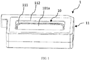
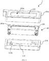
- FIG. 1 , FIG. 2 , and FIG. 3 are a three-dimensional diagram, a schematic exploded view, and a schematic diagram of a two-way receiver, respectively, of a receiver apparatus according to a first embodiment of this disclosure.
- this embodiment provides a receiver apparatus 1.
- the receiver apparatus 1 includes a two-way receiver 10 and an acoustic chamber support 11.
- the two-way receiver 10 has a first sound output surface 101 and a second sound output surface 102, and the first sound output surface 101 and the second sound output surface 102 are opposite each other.
- the first sound output surface 101 has a first sound output region 101a
- the second sound output surface 102 has a second sound output region 102a
- the first sound output region 101a and the second sound output region 102a are staggered, so that the two-way receiver 10 can achieve two-way sound output.
- the first sound output region 101a is located at the center of the first sound output surface 101
- two second sound output regions 102a are provided that are located at a first edge and a second edge of the second sound output surface 102.
- the first edge and the second edge are opposite each other, so the two second sound output regions 102a and the first sound output region 101a are staggered.
- an area of the first sound output region 101a is larger than an area of the two second sound output regions 102a.
- the second sound output region 102a can be located at the periphery of the second sound output surface 102, so that the second sound output region 102a and the first sound output region 101a are staggered.
- the first sound output region 101a and the second sound output region 102a are staggered to mainly improve a sound output effect of the two-way receiver 10.
- the first sound output region 101a and the second sound output region 102a may be aligned, which is not further described herein.
- the acoustic chamber support 11 has an acoustic chamber 111, and the two-way receiver 10 is provided in the acoustic chamber 111.
- the acoustic chamber support 11 has a first sound outlet 112 in a surface corresponding to the first sound output surface 101 of the two-way receiver 10, and the acoustic chamber support 11 has a second sound outlet 113 in a surface corresponding to the second sound output surface 102 of the two-way receiver 10.
- the first sound outlet 112 and the second sound outlet 113 are opposite each other and both communicate with the acoustic chamber 111.
- a first sound source emitted from the first sound output region 101a is output from the first sound outlet 112, and a second sound source emitted from the second sound output region 102a is output from the second sound outlet 113.
- An output direction of the first sound source is different from that of the second sound source, so that the receiver apparatus 1 in this embodiment achieves two-way sound output.
- the acoustic chamber support 11 in this embodiment includes a first acoustic chamber support 11a and a second acoustic chamber support 11b.
- the first acoustic chamber support 11a has a first acoustic chamber 111a
- the second acoustic chamber support 11b has a second acoustic chamber 111b.
- the first sound outlet 112 is provided at the first acoustic chamber support 11a and communicates with the first acoustic chamber 111a.
- the second sound outlet 113 is provided at the second acoustic chamber support 11b and communicates with the second acoustic chamber 111b.
- the second acoustic chamber support 11b is connected to the first acoustic chamber support 11a, the second sound outlet 113 is opposite the first sound outlet 112, and the first acoustic chamber 111a and the second acoustic chamber 111b are in communication with each other and jointly form the acoustic chamber 111 accommodating the receiver apparatus 1.
- the first acoustic chamber support 11a and the second acoustic chamber support 11b are detachably connected.
- the first sound source or the second sound source propagates in the acoustic chamber 111, so that the first sound source or the second sound source generates a high-band cutoff frequency and a high-frequency peak, to correct high-frequency noise of the first sound source or the second sound source, increase an intermediate frequency of the first sound source or the second sound source to reduce the high-frequency noise, reduce high band extension, and improve conversion efficiency of the first sound source or the second sound source.
- the first sound source or the second sound source is improved by the acoustic chamber 111, and the improved first sound source or second sound source is output through the first sound outlet 112 or the second sound outlet 113, thereby effectively improving a sound output effect of the receiver apparatus 1.
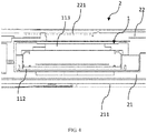
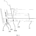
- FIG. 4 , FIG. 5 , and FIG. 6 are a cross-sectional view, a partial cross-sectional view of a main board cover, and a partial cross-sectional view of a middle frame, respectively, of a mobile device according to a second embodiment of this disclosure.
- the receiver apparatus 1 according to the first embodiment is applied to a mobile device 2 in this embodiment, and the mobile device 2 may be a mobile phone or a tablet computer.
- the mobile device 2 in this embodiment includes a main board cover 21 and a middle frame 22.
- the receiver apparatus 1 is provided between the main board cover 21 and the middle frame 22.
- the main board cover 21 is located on a surface of the receiver apparatus 1, where a first sound outlet 112 is provided in this surface.
- the middle frame 22 is located on a surface of the receiver apparatus 1, where a second sound outlet 113 is provided in this surface.
- the main board cover 21 has a first sound output hole 211 on one side.
- the first sound output hole 211 communicates with the first sound outlet 112 of the receiver apparatus 1, so that a first sound source emitted by the first sound outlet 112 is output from the first sound output hole 211.
- the middle frame 22 has a second sound output hole 221 on one side, and the second sound output hole 221 communicates with the second sound outlet 113 of the receiver apparatus 1, so that a second sound source emitted by the second sound outlet 113 is output from the second sound output hole 221.
- a propagation direction of the first sound source emitted from the first sound output hole 211 is different from a propagation direction of the second sound source emitted from the second sound output hole 221, so that the mobile device 2 achieves two-way sound output.
- the first sound output hole 211 and the second sound output hole 221 in this embodiment are opposite each other.
- the first sound output hole 211 and the second sound output hole 221 may not be opposite each other, provided that the first sound output hole 211 communicates with the first sound outlet 112 and the second sound output hole 221 communicates with the second sound outlet 113, to allow the first sound source to come out from the first sound output hole 211, and the second sound source from the second sound output hole 221.
- the first sound output hole 211 may communicate with the first sound outlet 112, and the second sound output hole 221 may communicate with the second sound outlet 113. Details are not described herein.
- the first sound output hole 211 and the first sound outlet 112 in this embodiment are communicated through a first groove 212 of the main board cover 21.
- One end of the first groove 212 is located on a surface of the receiver apparatus 1, where the first sound outlet 112 is provided in this surface.
- the first sound output hole 211 is provided at the other end of the first groove 212.
- a first sound source propagation channel 212a is provided in the first groove 212.
- Both the first sound outlet 112 and the first sound output hole 211 communicate with the first sound source propagation channel 212a.
- a first sound source emitted by the first sound outlet 112 propagates along the first sound source propagation channel 212a to the first sound output hole 211, so that the first sound source is output from the first sound output hole 211.
- the second sound output hole 221 and the second sound outlet 113 in this embodiment are communicated through a second groove 222 of the middle frame 22.
- One end of the second groove 222 is located on a surface of the two-way sound output apparatus 1, where the second sound outlet 113 is provided in this surface, and the second sound output hole 221 is provided at the other end of the second groove 222.
- a second sound source propagation channel 222a is provided in the second groove 222.
- Both the second sound outlet 113 and the second sound output hole 221 communicate with the second sound source propagation channel 222a, and a second sound source emitted by the second sound outlet 113 propagates along the second sound source propagation channel 222a to the second sound output hole 221, so that the second sound source is output from the second sound outlet 221.
- cross-sectional shapes of the first groove 212 and the second groove 222 in this embodiment are L-shaped. Therefore, a propagation path of the first sound source along the first sound source propagation channel 212a and a propagation path of the second sound source along the second sound source propagation channel 222a are also L-shaped. This is only one embodiment of this disclosure.
- the cross-sectional shapes of the first groove 212 and the second groove 222 may be determined based on internal configuration of the mobile device 2. Details are not described herein.
- one or more first sound output holes 211 and one or more second sound output holes 221 may be provided, and these quantities are determined as required by a user. Details are not described herein.
- the mobile device 2 in this embodiment further includes a first decorative hood 23 and a second decorative hood 24.
- the first decorative hood 23 is provided on one side of the main board cover 21 and is provided above the first sound output hole 211 of the main board cover 21.
- the first decorative hood 23 has a plurality of first holes 231 communicating with the first sound output hole 211, so that the first sound output hole 211 and the first sound outlet 112 are communicated with each other through the plurality of first holes 231.
- the second decorative hood 24 is provided on one side of the middle frame 22 and is provided above the second sound output hole 221 of the middle frame 22.
- the second decorative hood 24 has a plurality of second holes 241 communicating with the second sound output hole 221, so that the second sound output hole 221 and the second sound outlet 113 are communicated with each other through the plurality of second holes 241.
- the first decorative hood 23 and the second decorative hood 24 is mainly intended to prevent dust or foreign objects outside the mobile device 2 from entering the mobile device 2 through the first sound output hole 211 and the second sound output hole 221.
- the first decorative hood 23 in this embodiment is provided at the other end of the first groove 212.
- the second decorative hood 24 serves as a bottom of the second groove 222, and forms the second groove 222 together with a through-groove running through the middle frame 22.
- this disclosure provides a receiver apparatus and a mobile device.
- the receiver apparatus achieves two-way sound output through provision of the two-way sound output receiver, and the acoustic chamber support encloses the two-way sound output receiver to improve a sound output effect of the receiver apparatus.
- the mobile device uses the receiver apparatus provided in this disclosure to achieve simultaneous sound output at two screens, and saves space of the mobile device, so that the mobile device can still be light and thin, thereby reducing overall costs.
Landscapes
- Engineering & Computer Science (AREA)
- Signal Processing (AREA)
- Physics & Mathematics (AREA)
- Acoustics & Sound (AREA)
- Health & Medical Sciences (AREA)
- Otolaryngology (AREA)
- Computer Networks & Wireless Communication (AREA)
- Telephone Set Structure (AREA)
- Structure Of Receivers (AREA)
- Details Of Audible-Bandwidth Transducers (AREA)
Abstract
Description
- This application claims priority to
Chinese Patent Application No. 201811358285.0 - This disclosure relates to the field of mobile devices, and in particular, to a receiver apparatus and a mobile device.
- With rapid development of material technologies and communication technologies, mobile devices with novel appearances or using special materials continue to emerge, and mobile devices with front and rear screens are also one of future trends. A mobile device with double-sided screens is provided with two screens at the front and the back. This compresses space of the mobile device in a thickness direction. Such a mobile device with front and rear screens must be provided with sound output components on both the front and the back. Because the space of the mobile device in the thickness direction is compressed by the front and rear screens, a sound output structure of a receiver in conventional technologies cannot be applied to the mobile device with front and rear screens. Therefore, the mobile device with front and rear screens cannot achieve simultaneous sound output at the two screens.
- Embodiments of this disclosure provide a receiver apparatus and a mobile device to resolve the problem that a mobile device with front and rear screens in conventional technologies cannot achieve simultaneous sound output at the two screens.
- In order to resolve the foregoing technical problem, this disclosure is implemented as follows:
- According to a first aspect, a receiver apparatus is provided. The receiver apparatus includes a two-way receiver and an acoustic chamber support, where the two-way receiver has a first sound output region and a second sound output region, and the acoustic chamber support has an acoustic chamber, where the two-way receiver is provided in the acoustic chamber, and the acoustic chamber support has a first sound outlet and the first sound outlet and a second sound outlet that both communicate with the acoustic chamber, where the first sound outlet and the second sound outlet are opposite each other, the first sound outlet communicates with the first sound output region, and the second sound outlet communicates with the second sound output region.
- According to a second aspect, a mobile device using the receiver apparatus according to the first aspect is provided.
- In the embodiments of this disclosure, the receiver apparatus achieves two-way sound output through provision of the two-way sound output receiver, and the acoustic chamber support encloses the two-way sound output receiver to improve a sound output effect of the receiver apparatus. The mobile device uses the receiver apparatus provided in this disclosure to achieve simultaneous sound output at two screens.
- The drawings described herein are used to provide a further understanding of this disclosure, and constitute a part of this disclosure. Exemplary embodiments of this disclosure and descriptions thereof are used to explain this disclosure, but do not constitute any inappropriate limitation on this disclosure. In the drawings:
-
FIG. 1 is a three-dimensional diagram of a receiver apparatus according to a first embodiment of this disclosure; -
FIG. 2 is a schematic exploded view of the receiver apparatus according to the first embodiment of this disclosure; -
FIG. 3 is a schematic diagram of a two-way receiver according to the first embodiment of this disclosure; -
FIG. 4 is a cross-sectional view of a mobile device according to a second embodiment of this disclosure; -
FIG. 5 is a partial cross-sectional view of a main board cover according to the second embodiment of this disclosure; and -
FIG. 6 is a partial cross-sectional view of a middle frame according to the second embodiment of this disclosure. - The following clearly and completely describes the technical solutions in the embodiments of this disclosure with reference to the accompanying drawings in the embodiments of this disclosure. Apparently, the described embodiments are merely a part rather than all of the embodiments of this disclosure. All other embodiments that a person of ordinary skill in the art obtains without creative efforts based on the embodiments of this disclosure shall fall within the protection scope of this disclosure.
-
FIG. 1 ,FIG. 2 , andFIG. 3 are a three-dimensional diagram, a schematic exploded view, and a schematic diagram of a two-way receiver, respectively, of a receiver apparatus according to a first embodiment of this disclosure. As shown in the figures, this embodiment provides areceiver apparatus 1. Thereceiver apparatus 1 includes a two-way receiver 10 and anacoustic chamber support 11. The two-way receiver 10 has a firstsound output surface 101 and a secondsound output surface 102, and the firstsound output surface 101 and the secondsound output surface 102 are opposite each other. The firstsound output surface 101 has a firstsound output region 101a, the secondsound output surface 102 has a secondsound output region 102a, and the firstsound output region 101a and the secondsound output region 102a are staggered, so that the two-way receiver 10 can achieve two-way sound output. In this embodiment, the firstsound output region 101a is located at the center of the firstsound output surface 101, and two secondsound output regions 102a are provided that are located at a first edge and a second edge of the secondsound output surface 102. The first edge and the second edge are opposite each other, so the two secondsound output regions 102a and the firstsound output region 101a are staggered. Obviously, an area of the firstsound output region 101a is larger than an area of the two secondsound output regions 102a. When one secondsound output region 102a is provided, the secondsound output region 102a can be located at the periphery of the secondsound output surface 102, so that the secondsound output region 102a and the firstsound output region 101a are staggered. In this embodiment, the firstsound output region 101a and the secondsound output region 102a are staggered to mainly improve a sound output effect of the two-way receiver 10. Certainly, the firstsound output region 101a and the secondsound output region 102a may be aligned, which is not further described herein. - The
acoustic chamber support 11 has anacoustic chamber 111, and the two-way receiver 10 is provided in theacoustic chamber 111. Theacoustic chamber support 11 has afirst sound outlet 112 in a surface corresponding to the firstsound output surface 101 of the two-way receiver 10, and theacoustic chamber support 11 has asecond sound outlet 113 in a surface corresponding to the secondsound output surface 102 of the two-way receiver 10. Thefirst sound outlet 112 and thesecond sound outlet 113 are opposite each other and both communicate with theacoustic chamber 111. A first sound source emitted from the firstsound output region 101a is output from thefirst sound outlet 112, and a second sound source emitted from the secondsound output region 102a is output from thesecond sound outlet 113. An output direction of the first sound source is different from that of the second sound source, so that thereceiver apparatus 1 in this embodiment achieves two-way sound output. - Optionally, the acoustic chamber support 11 in this embodiment includes a first
acoustic chamber support 11a and a secondacoustic chamber support 11b. The firstacoustic chamber support 11a has a firstacoustic chamber 111a, and the secondacoustic chamber support 11b has a secondacoustic chamber 111b. Thefirst sound outlet 112 is provided at the first acoustic chamber support 11a and communicates with the firstacoustic chamber 111a. Thesecond sound outlet 113 is provided at the secondacoustic chamber support 11b and communicates with the secondacoustic chamber 111b. The secondacoustic chamber support 11b is connected to the firstacoustic chamber support 11a, thesecond sound outlet 113 is opposite thefirst sound outlet 112, and the firstacoustic chamber 111a and the secondacoustic chamber 111b are in communication with each other and jointly form theacoustic chamber 111 accommodating thereceiver apparatus 1. The first acoustic chamber support 11a and the secondacoustic chamber support 11b are detachably connected. - When the first sound source is emitted from the first
sound output region 101a and the second sound source is emitted from the secondsound output region 102a, the first sound source or the second sound source propagates in theacoustic chamber 111, so that the first sound source or the second sound source generates a high-band cutoff frequency and a high-frequency peak, to correct high-frequency noise of the first sound source or the second sound source, increase an intermediate frequency of the first sound source or the second sound source to reduce the high-frequency noise, reduce high band extension, and improve conversion efficiency of the first sound source or the second sound source. In other words, the first sound source or the second sound source is improved by theacoustic chamber 111, and the improved first sound source or second sound source is output through thefirst sound outlet 112 or thesecond sound outlet 113, thereby effectively improving a sound output effect of thereceiver apparatus 1. -
FIG. 4 ,FIG. 5 , andFIG. 6 are a cross-sectional view, a partial cross-sectional view of a main board cover, and a partial cross-sectional view of a middle frame, respectively, of a mobile device according to a second embodiment of this disclosure. As shown in the figures, thereceiver apparatus 1 according to the first embodiment is applied to amobile device 2 in this embodiment, and themobile device 2 may be a mobile phone or a tablet computer. Themobile device 2 in this embodiment includes amain board cover 21 and amiddle frame 22. Thereceiver apparatus 1 is provided between themain board cover 21 and themiddle frame 22. Themain board cover 21 is located on a surface of thereceiver apparatus 1, where afirst sound outlet 112 is provided in this surface. Themiddle frame 22 is located on a surface of thereceiver apparatus 1, where asecond sound outlet 113 is provided in this surface. Themain board cover 21 has a firstsound output hole 211 on one side. The firstsound output hole 211 communicates with thefirst sound outlet 112 of thereceiver apparatus 1, so that a first sound source emitted by thefirst sound outlet 112 is output from the firstsound output hole 211. Themiddle frame 22 has a secondsound output hole 221 on one side, and the secondsound output hole 221 communicates with thesecond sound outlet 113 of thereceiver apparatus 1, so that a second sound source emitted by thesecond sound outlet 113 is output from the secondsound output hole 221. A propagation direction of the first sound source emitted from the firstsound output hole 211 is different from a propagation direction of the second sound source emitted from the secondsound output hole 221, so that themobile device 2 achieves two-way sound output. - Optionally, the first
sound output hole 211 and the secondsound output hole 221 in this embodiment are opposite each other. Certainly, the firstsound output hole 211 and the secondsound output hole 221 may not be opposite each other, provided that the firstsound output hole 211 communicates with thefirst sound outlet 112 and the secondsound output hole 221 communicates with thesecond sound outlet 113, to allow the first sound source to come out from the firstsound output hole 211, and the second sound source from the secondsound output hole 221. Certainly, alternatively, the firstsound output hole 211 may communicate with thefirst sound outlet 112, and the secondsound output hole 221 may communicate with thesecond sound outlet 113. Details are not described herein. - Optionally, the first
sound output hole 211 and thefirst sound outlet 112 in this embodiment are communicated through afirst groove 212 of themain board cover 21. One end of thefirst groove 212 is located on a surface of thereceiver apparatus 1, where thefirst sound outlet 112 is provided in this surface. The firstsound output hole 211 is provided at the other end of thefirst groove 212. A first soundsource propagation channel 212a is provided in thefirst groove 212. Both thefirst sound outlet 112 and the firstsound output hole 211 communicate with the first soundsource propagation channel 212a. A first sound source emitted by thefirst sound outlet 112 propagates along the first soundsource propagation channel 212a to the firstsound output hole 211, so that the first sound source is output from the firstsound output hole 211. - Optionally, the second
sound output hole 221 and thesecond sound outlet 113 in this embodiment are communicated through asecond groove 222 of themiddle frame 22. One end of thesecond groove 222 is located on a surface of the two-waysound output apparatus 1, where thesecond sound outlet 113 is provided in this surface, and the secondsound output hole 221 is provided at the other end of thesecond groove 222. A second soundsource propagation channel 222a is provided in thesecond groove 222. Both thesecond sound outlet 113 and the secondsound output hole 221 communicate with the second soundsource propagation channel 222a, and a second sound source emitted by thesecond sound outlet 113 propagates along the second soundsource propagation channel 222a to the secondsound output hole 221, so that the second sound source is output from thesecond sound outlet 221. - Furthermore, cross-sectional shapes of the
first groove 212 and thesecond groove 222 in this embodiment are L-shaped. Therefore, a propagation path of the first sound source along the first soundsource propagation channel 212a and a propagation path of the second sound source along the second soundsource propagation channel 222a are also L-shaped. This is only one embodiment of this disclosure. The cross-sectional shapes of thefirst groove 212 and thesecond groove 222 may be determined based on internal configuration of themobile device 2. Details are not described herein. - Optionally, in this embodiment, one or more first sound output holes 211 and one or more second sound output holes 221 may be provided, and these quantities are determined as required by a user. Details are not described herein.
- Optionally, the
mobile device 2 in this embodiment further includes a firstdecorative hood 23 and a seconddecorative hood 24. The firstdecorative hood 23 is provided on one side of themain board cover 21 and is provided above the firstsound output hole 211 of themain board cover 21. The firstdecorative hood 23 has a plurality offirst holes 231 communicating with the firstsound output hole 211, so that the firstsound output hole 211 and thefirst sound outlet 112 are communicated with each other through the plurality offirst holes 231. The seconddecorative hood 24 is provided on one side of themiddle frame 22 and is provided above the secondsound output hole 221 of themiddle frame 22. The seconddecorative hood 24 has a plurality ofsecond holes 241 communicating with the secondsound output hole 221, so that the secondsound output hole 221 and thesecond sound outlet 113 are communicated with each other through the plurality ofsecond holes 241. The firstdecorative hood 23 and the seconddecorative hood 24 is mainly intended to prevent dust or foreign objects outside themobile device 2 from entering themobile device 2 through the firstsound output hole 211 and the secondsound output hole 221. The firstdecorative hood 23 in this embodiment is provided at the other end of thefirst groove 212. The seconddecorative hood 24 serves as a bottom of thesecond groove 222, and forms thesecond groove 222 together with a through-groove running through themiddle frame 22. - In conclusion, this disclosure provides a receiver apparatus and a mobile device. The receiver apparatus achieves two-way sound output through provision of the two-way sound output receiver, and the acoustic chamber support encloses the two-way sound output receiver to improve a sound output effect of the receiver apparatus. The mobile device uses the receiver apparatus provided in this disclosure to achieve simultaneous sound output at two screens, and saves space of the mobile device, so that the mobile device can still be light and thin, thereby reducing overall costs.
- It should be noted that, in this specification, the terms "include", "comprise", or any of their variants are intended to cover a non-exclusive inclusion, such that a process, a method, an article, or an apparatus that includes a list of elements not only includes those elements but also includes other elements that are not expressly listed, or further includes elements inherent to such a process, method, article, or apparatus. In absence of more constraints, an element preceded by "includes a..." does not preclude the existence of other identical elements in the process, method, article, or apparatus that includes the element.
- The embodiments of this disclosure are described above with reference to the accompanying drawings, but this disclosure is not limited to the embodiments. The embodiments are only illustrative rather than restrictive. Inspired by this disclosure, a person of ordinary skill in the art can still derive a plurality of variations without departing from the essence of this disclosure and the protection scope of the claims. All these variations shall fall within the protection of this disclosure.
Claims (11)
- A receiver apparatus, comprising a two-way receiver and an acoustic chamber support, wherein the two-way receiver has a first sound output region and a second sound output region, and the acoustic chamber support has an acoustic chamber, wherein the two-way receiver is provided in the acoustic chamber, and the acoustic chamber support has a first sound outlet and a second sound outlet that both communicate with the acoustic chamber, wherein the first sound outlet and the second sound outlet are opposite each other, the first sound outlet communicates with the first sound output region, and the second sound outlet communicates with the second sound output region.
- The receiver apparatus according to claim 1, wherein the first sound output region is located at the center of a first sound output surface of the two-way receiver, and the second sound output region is located at the periphery of a second sound output surface of the two-way receiver, wherein the first sound output surface and the second sound output surface are opposite each other.
- The receiver apparatus according to claim 2, wherein two second sound output regions are provided, the two second sound output regions are located at a first edge and a second edge of the second sound output surface, and the first edge and the second edge are opposite each other.
- The receiver apparatus according to claim 1, wherein the acoustic chamber support comprises a first acoustic chamber support and a second acoustic chamber support connected to the first acoustic chamber support, the first acoustic chamber support has a first acoustic chamber and the first sound outlet communicating with the first acoustic chamber, the second acoustic chamber support has a second acoustic chamber and the second sound outlet communicating with the second acoustic chamber, and the first acoustic chamber and the second acoustic chamber are in communication with each other and together form the acoustic chamber.
- The receiver apparatus according to claim 4, wherein the first acoustic chamber support and the second acoustic chamber support are detachably connected.
- A mobile device, comprising the receiver apparatus according to any one of claims 1 to 5.
- The mobile device according to claim 6, wherein the mobile device has a main board cover and a middle frame, the two-way sound output receiver apparatus is provided between the main board cover and the middle frame, one of the first sound outlet and the second sound outlet communicates with a first sound output hole of the main board cover, and the other of the first sound outlet and the second sound outlet communicates with a second sound output hole of the middle frame.
- The mobile device according to claim 7, wherein the first sound outlet communicates with the first sound output hole, the second sound outlet communicates with the second sound output hole, the main board cover has a first groove on one side, the first sound outlet is located at one end of the first groove, the first sound output hole is located at the other end of the first groove, and the first sound outlet and the first sound output hole are communicated through a first sound source propagation channel of the first groove.
- The mobile device according to claim 8, further comprising a first decorative hood, wherein the first decorative hood is provided on one side of the main board cover and located above the first sound output hole, and has a plurality of first holes communicating with the first sound output hole.
- The mobile device according to claim 7, wherein the middle frame has a second groove on one side, the second sound outlet is located at one end of the second groove, the second sound output hole is located at the other end of the second groove, and the second sound outlet and the second sound output hole are communicated through a second sound source propagation channel of the second groove.
- The mobile device according to claim 10, further comprising a second decorative hood, wherein the second decorative hood is provided on one side of the middle frame and located above the second sound output hole, and has a plurality of second holes communicating with the second sound output hole.
Applications Claiming Priority (2)
| Application Number | Priority Date | Filing Date | Title |
|---|---|---|---|
| CN201811358285.0A CN109511029B (en) | 2018-11-15 | 2018-11-15 | Mobile device |
| PCT/CN2019/116122 WO2020098554A1 (en) | 2018-11-15 | 2019-11-07 | Receiver apparatus and mobile device |
Publications (3)
| Publication Number | Publication Date |
|---|---|
| EP3883224A1 true EP3883224A1 (en) | 2021-09-22 |
| EP3883224A4 EP3883224A4 (en) | 2022-01-05 |
| EP3883224B1 EP3883224B1 (en) | 2023-08-09 |
Family
ID=65748554
Family Applications (1)
| Application Number | Title | Priority Date | Filing Date |
|---|---|---|---|
| EP19884195.9A Active EP3883224B1 (en) | 2018-11-15 | 2019-11-07 | Receiver apparatus and mobile device |
Country Status (7)
| Country | Link |
|---|---|
| US (1) | US11799506B2 (en) |
| EP (1) | EP3883224B1 (en) |
| CN (1) | CN109511029B (en) |
| CA (1) | CA3120007C (en) |
| ES (1) | ES2955041T3 (en) |
| UA (1) | UA126764C2 (en) |
| WO (1) | WO2020098554A1 (en) |
Families Citing this family (4)
| Publication number | Priority date | Publication date | Assignee | Title |
|---|---|---|---|---|
| CN109511029B (en) | 2018-11-15 | 2022-05-27 | 维沃移动通信有限公司 | Mobile device |
| KR102682500B1 (en) * | 2019-03-26 | 2024-07-08 | 삼성디스플레이 주식회사 | Foldable display device and method for providng the sound of the same |
| CN110166610B (en) * | 2019-05-31 | 2020-06-23 | 维沃移动通信有限公司 | A kind of mobile terminal and switching method of sound outlet |
| CN113438341B (en) * | 2020-01-22 | 2024-08-27 | 华为技术有限公司 | Method and terminal for realizing stereo output |
Family Cites Families (18)
| Publication number | Priority date | Publication date | Assignee | Title |
|---|---|---|---|---|
| KR100506949B1 (en) * | 2000-08-24 | 2005-08-09 | 지에스엠텔레콤(주) | Speaker Unit Having A Double Function |
| CN1568070A (en) * | 2003-06-30 | 2005-01-19 | 王兴荣 | Planar series magnetic circuit double sided sounder |
| KR100624787B1 (en) * | 2004-12-03 | 2006-09-18 | 엘지전자 주식회사 | Foldable mobile communication terminal with two-way speaker |
| KR100664229B1 (en) * | 2005-09-29 | 2007-01-04 | 엘지전자 주식회사 | Portable terminal with two way speaker |
| KR101313977B1 (en) * | 2009-12-18 | 2013-10-01 | 한국전자통신연구원 | Iptv service control method and system using mobile device |
| CN201893826U (en) * | 2010-12-17 | 2011-07-06 | 英华达(南京)科技有限公司 | Mobile phone with double-faced answer |
| CN201937660U (en) * | 2011-02-18 | 2011-08-17 | 夏新科技有限公司 | Double-microphone flip mobile phone |
| KR101395050B1 (en) | 2012-10-25 | 2014-05-19 | 주식회사 이엠텍 | Sound transducer with ventilation structure |
| CN204465855U (en) * | 2015-02-13 | 2015-07-08 | 瑞声光电科技(常州)有限公司 | Loud speaker |
| CN105227719B (en) * | 2015-10-14 | 2018-04-03 | 广东欧珀移动通信有限公司 | A kind of mobile terminal |
| KR101880465B1 (en) * | 2017-09-22 | 2018-07-20 | 엘지전자 주식회사 | Mobile terminal |
| CN108566597B (en) * | 2018-04-24 | 2020-05-19 | 歌尔股份有限公司 | Sound production device |
| CN108390972B (en) * | 2018-05-29 | 2020-08-18 | 维沃移动通信有限公司 | Mobile terminal and control method thereof |
| CN108566606B (en) * | 2018-06-25 | 2020-03-17 | 歌尔股份有限公司 | Sound production device and portable terminal |
| CN108632727B (en) * | 2018-06-25 | 2024-09-03 | 歌尔股份有限公司 | Portable terminal |
| CN108566605A (en) * | 2018-06-26 | 2018-09-21 | 潍坊帕萨蒂经贸有限公司 | Loud speaker |
| CN108924313B (en) * | 2018-07-27 | 2020-10-16 | 维沃移动通信有限公司 | An electronic device and a method for receiving a call |
| CN109511029B (en) * | 2018-11-15 | 2022-05-27 | 维沃移动通信有限公司 | Mobile device |
-
2018
- 2018-11-15 CN CN201811358285.0A patent/CN109511029B/en active Active
-
2019
- 2019-11-07 ES ES19884195T patent/ES2955041T3/en active Active
- 2019-11-07 WO PCT/CN2019/116122 patent/WO2020098554A1/en not_active Ceased
- 2019-11-07 EP EP19884195.9A patent/EP3883224B1/en active Active
- 2019-11-07 CA CA3120007A patent/CA3120007C/en active Active
- 2019-11-07 UA UAA202103193A patent/UA126764C2/en unknown
-
2021
- 2021-05-14 US US17/321,392 patent/US11799506B2/en active Active
Also Published As
| Publication number | Publication date |
|---|---|
| US20210273669A1 (en) | 2021-09-02 |
| EP3883224B1 (en) | 2023-08-09 |
| WO2020098554A1 (en) | 2020-05-22 |
| CN109511029B (en) | 2022-05-27 |
| CN109511029A (en) | 2019-03-22 |
| EP3883224A4 (en) | 2022-01-05 |
| ES2955041T3 (en) | 2023-11-28 |
| CA3120007C (en) | 2023-07-18 |
| CA3120007A1 (en) | 2020-05-22 |
| US11799506B2 (en) | 2023-10-24 |
| UA126764C2 (en) | 2023-01-25 |
Similar Documents
| Publication | Publication Date | Title |
|---|---|---|
| US11799506B2 (en) | Receiver apparatus and mobile device | |
| CN110913048B (en) | Electronic device | |
| TWI577082B (en) | Communication device | |
| CN105655706B (en) | Metal terminal back cover and terminal | |
| US10567868B2 (en) | Sound generator | |
| US20020137475A1 (en) | Anti electromagnetic wave box for a mobile phone | |
| EP3823258B1 (en) | Mobile terminal | |
| US9049505B2 (en) | Electronic device with loudspeaker | |
| CN109218860A (en) | Loudspeaker enclosure | |
| US20110243359A1 (en) | Speaker system with subwoofer | |
| US8804990B2 (en) | Portable apparatus | |
| WO2019019325A1 (en) | Loudspeaker module and electronic apparatus | |
| WO2019179352A1 (en) | Mobile terminal | |
| WO2019076205A1 (en) | Terminal | |
| US20180031683A1 (en) | Combined structure of piezoelectric receiver and ultrasonic generator | |
| JP6166992B2 (en) | Mobile device | |
| US10887686B2 (en) | Directional microphone | |
| CN107197398A (en) | Loudspeaker assembly and mobile terminal | |
| US20120321117A1 (en) | Portable electronic device having sound emission holes aligned with speaker at recess of rear cover | |
| WO2018014672A1 (en) | Anti-dust apparatus for acoustic device of mobile terminal and mobile terminal | |
| US8358776B1 (en) | Telephone microphone | |
| EP1897351B1 (en) | A speaker apparatus combining earpiece and hands free functions | |
| CN206922972U (en) | Loudspeaker assembly and mobile terminal | |
| CN115623398B (en) | electronic devices | |
| US20060088179A1 (en) | Moveable device component with acoustic porting |
Legal Events
| Date | Code | Title | Description |
|---|---|---|---|
| STAA | Information on the status of an ep patent application or granted ep patent |
Free format text: STATUS: THE INTERNATIONAL PUBLICATION HAS BEEN MADE |
|
| PUAI | Public reference made under article 153(3) epc to a published international application that has entered the european phase |
Free format text: ORIGINAL CODE: 0009012 |
|
| STAA | Information on the status of an ep patent application or granted ep patent |
Free format text: STATUS: REQUEST FOR EXAMINATION WAS MADE |
|
| 17P | Request for examination filed |
Effective date: 20210528 |
|
| AK | Designated contracting states |
Kind code of ref document: A1 Designated state(s): AL AT BE BG CH CY CZ DE DK EE ES FI FR GB GR HR HU IE IS IT LI LT LU LV MC MK MT NL NO PL PT RO RS SE SI SK SM TR |
|
| A4 | Supplementary search report drawn up and despatched |
Effective date: 20211207 |
|
| RIC1 | Information provided on ipc code assigned before grant |
Ipc: H04R 9/00 20060101ALI20211201BHEP Ipc: H04M 1/03 20060101AFI20211201BHEP |
|
| DAV | Request for validation of the european patent (deleted) | ||
| DAX | Request for extension of the european patent (deleted) | ||
| REG | Reference to a national code |
Ref country code: DE Ref legal event code: R079 Free format text: PREVIOUS MAIN CLASS: H04M0001030000 Ipc: H04B0001160000 Ref country code: DE Ref legal event code: R079 Ref document number: 602019034864 Country of ref document: DE Free format text: PREVIOUS MAIN CLASS: H04M0001030000 Ipc: H04B0001160000 |
|
| GRAP | Despatch of communication of intention to grant a patent |
Free format text: ORIGINAL CODE: EPIDOSNIGR1 |
|
| RIC1 | Information provided on ipc code assigned before grant |
Ipc: H04M 1/03 20060101ALI20230331BHEP Ipc: H04R 1/34 20060101ALI20230331BHEP Ipc: H04R 1/02 20060101ALI20230331BHEP Ipc: H04B 1/3827 20150101ALI20230331BHEP Ipc: H04B 1/16 20060101AFI20230331BHEP |
|
| STAA | Information on the status of an ep patent application or granted ep patent |
Free format text: STATUS: GRANT OF PATENT IS INTENDED |
|
| INTG | Intention to grant announced |
Effective date: 20230511 |
|
| GRAS | Grant fee paid |
Free format text: ORIGINAL CODE: EPIDOSNIGR3 |
|
| GRAA | (expected) grant |
Free format text: ORIGINAL CODE: 0009210 |
|
| STAA | Information on the status of an ep patent application or granted ep patent |
Free format text: STATUS: THE PATENT HAS BEEN GRANTED |
|
| AK | Designated contracting states |
Kind code of ref document: B1 Designated state(s): AL AT BE BG CH CY CZ DE DK EE ES FI FR GB GR HR HU IE IS IT LI LT LU LV MC MK MT NL NO PL PT RO RS SE SI SK SM TR |
|
| REG | Reference to a national code |
Ref country code: GB Ref legal event code: FG4D |
|
| REG | Reference to a national code |
Ref country code: CH Ref legal event code: EP |
|
| REG | Reference to a national code |
Ref country code: IE Ref legal event code: FG4D |
|
| REG | Reference to a national code |
Ref country code: DE Ref legal event code: R096 Ref document number: 602019034864 Country of ref document: DE |
|
| REG | Reference to a national code |
Ref country code: NL Ref legal event code: FP |
|
| REG | Reference to a national code |
Ref country code: LT Ref legal event code: MG9D |
|
| REG | Reference to a national code |
Ref country code: ES Ref legal event code: FG2A Ref document number: 2955041 Country of ref document: ES Kind code of ref document: T3 Effective date: 20231128 |
|
| REG | Reference to a national code |
Ref country code: AT Ref legal event code: MK05 Ref document number: 1598677 Country of ref document: AT Kind code of ref document: T Effective date: 20230809 |
|
| PG25 | Lapsed in a contracting state [announced via postgrant information from national office to epo] |
Ref country code: GR Free format text: LAPSE BECAUSE OF FAILURE TO SUBMIT A TRANSLATION OF THE DESCRIPTION OR TO PAY THE FEE WITHIN THE PRESCRIBED TIME-LIMIT Effective date: 20231110 |
|
| PG25 | Lapsed in a contracting state [announced via postgrant information from national office to epo] |
Ref country code: IS Free format text: LAPSE BECAUSE OF FAILURE TO SUBMIT A TRANSLATION OF THE DESCRIPTION OR TO PAY THE FEE WITHIN THE PRESCRIBED TIME-LIMIT Effective date: 20231209 |
|
| PG25 | Lapsed in a contracting state [announced via postgrant information from national office to epo] |
Ref country code: SE Free format text: LAPSE BECAUSE OF FAILURE TO SUBMIT A TRANSLATION OF THE DESCRIPTION OR TO PAY THE FEE WITHIN THE PRESCRIBED TIME-LIMIT Effective date: 20230809 Ref country code: RS Free format text: LAPSE BECAUSE OF FAILURE TO SUBMIT A TRANSLATION OF THE DESCRIPTION OR TO PAY THE FEE WITHIN THE PRESCRIBED TIME-LIMIT Effective date: 20230809 Ref country code: PT Free format text: LAPSE BECAUSE OF FAILURE TO SUBMIT A TRANSLATION OF THE DESCRIPTION OR TO PAY THE FEE WITHIN THE PRESCRIBED TIME-LIMIT Effective date: 20231211 Ref country code: NO Free format text: LAPSE BECAUSE OF FAILURE TO SUBMIT A TRANSLATION OF THE DESCRIPTION OR TO PAY THE FEE WITHIN THE PRESCRIBED TIME-LIMIT Effective date: 20231109 Ref country code: LV Free format text: LAPSE BECAUSE OF FAILURE TO SUBMIT A TRANSLATION OF THE DESCRIPTION OR TO PAY THE FEE WITHIN THE PRESCRIBED TIME-LIMIT Effective date: 20230809 Ref country code: LT Free format text: LAPSE BECAUSE OF FAILURE TO SUBMIT A TRANSLATION OF THE DESCRIPTION OR TO PAY THE FEE WITHIN THE PRESCRIBED TIME-LIMIT Effective date: 20230809 Ref country code: IS Free format text: LAPSE BECAUSE OF FAILURE TO SUBMIT A TRANSLATION OF THE DESCRIPTION OR TO PAY THE FEE WITHIN THE PRESCRIBED TIME-LIMIT Effective date: 20231209 Ref country code: HR Free format text: LAPSE BECAUSE OF FAILURE TO SUBMIT A TRANSLATION OF THE DESCRIPTION OR TO PAY THE FEE WITHIN THE PRESCRIBED TIME-LIMIT Effective date: 20230809 Ref country code: GR Free format text: LAPSE BECAUSE OF FAILURE TO SUBMIT A TRANSLATION OF THE DESCRIPTION OR TO PAY THE FEE WITHIN THE PRESCRIBED TIME-LIMIT Effective date: 20231110 Ref country code: FI Free format text: LAPSE BECAUSE OF FAILURE TO SUBMIT A TRANSLATION OF THE DESCRIPTION OR TO PAY THE FEE WITHIN THE PRESCRIBED TIME-LIMIT Effective date: 20230809 Ref country code: AT Free format text: LAPSE BECAUSE OF FAILURE TO SUBMIT A TRANSLATION OF THE DESCRIPTION OR TO PAY THE FEE WITHIN THE PRESCRIBED TIME-LIMIT Effective date: 20230809 |
|
| PG25 | Lapsed in a contracting state [announced via postgrant information from national office to epo] |
Ref country code: PL Free format text: LAPSE BECAUSE OF FAILURE TO SUBMIT A TRANSLATION OF THE DESCRIPTION OR TO PAY THE FEE WITHIN THE PRESCRIBED TIME-LIMIT Effective date: 20230809 |
|
| PG25 | Lapsed in a contracting state [announced via postgrant information from national office to epo] |
Ref country code: SM Free format text: LAPSE BECAUSE OF FAILURE TO SUBMIT A TRANSLATION OF THE DESCRIPTION OR TO PAY THE FEE WITHIN THE PRESCRIBED TIME-LIMIT Effective date: 20230809 Ref country code: RO Free format text: LAPSE BECAUSE OF FAILURE TO SUBMIT A TRANSLATION OF THE DESCRIPTION OR TO PAY THE FEE WITHIN THE PRESCRIBED TIME-LIMIT Effective date: 20230809 Ref country code: EE Free format text: LAPSE BECAUSE OF FAILURE TO SUBMIT A TRANSLATION OF THE DESCRIPTION OR TO PAY THE FEE WITHIN THE PRESCRIBED TIME-LIMIT Effective date: 20230809 Ref country code: DK Free format text: LAPSE BECAUSE OF FAILURE TO SUBMIT A TRANSLATION OF THE DESCRIPTION OR TO PAY THE FEE WITHIN THE PRESCRIBED TIME-LIMIT Effective date: 20230809 Ref country code: CZ Free format text: LAPSE BECAUSE OF FAILURE TO SUBMIT A TRANSLATION OF THE DESCRIPTION OR TO PAY THE FEE WITHIN THE PRESCRIBED TIME-LIMIT Effective date: 20230809 Ref country code: SK Free format text: LAPSE BECAUSE OF FAILURE TO SUBMIT A TRANSLATION OF THE DESCRIPTION OR TO PAY THE FEE WITHIN THE PRESCRIBED TIME-LIMIT Effective date: 20230809 |
|
| REG | Reference to a national code |
Ref country code: DE Ref legal event code: R097 Ref document number: 602019034864 Country of ref document: DE |
|
| PLBE | No opposition filed within time limit |
Free format text: ORIGINAL CODE: 0009261 |
|
| STAA | Information on the status of an ep patent application or granted ep patent |
Free format text: STATUS: NO OPPOSITION FILED WITHIN TIME LIMIT |
|
| REG | Reference to a national code |
Ref country code: CH Ref legal event code: PL |
|
| PG25 | Lapsed in a contracting state [announced via postgrant information from national office to epo] |
Ref country code: MC Free format text: LAPSE BECAUSE OF FAILURE TO SUBMIT A TRANSLATION OF THE DESCRIPTION OR TO PAY THE FEE WITHIN THE PRESCRIBED TIME-LIMIT Effective date: 20230809 |
|
| PG25 | Lapsed in a contracting state [announced via postgrant information from national office to epo] |
Ref country code: LU Free format text: LAPSE BECAUSE OF NON-PAYMENT OF DUE FEES Effective date: 20231107 |
|
| 26N | No opposition filed |
Effective date: 20240513 |
|
| PG25 | Lapsed in a contracting state [announced via postgrant information from national office to epo] |
Ref country code: CH Free format text: LAPSE BECAUSE OF NON-PAYMENT OF DUE FEES Effective date: 20231130 |
|
| PG25 | Lapsed in a contracting state [announced via postgrant information from national office to epo] |
Ref country code: MC Free format text: LAPSE BECAUSE OF FAILURE TO SUBMIT A TRANSLATION OF THE DESCRIPTION OR TO PAY THE FEE WITHIN THE PRESCRIBED TIME-LIMIT Effective date: 20230809 Ref country code: LU Free format text: LAPSE BECAUSE OF NON-PAYMENT OF DUE FEES Effective date: 20231107 Ref country code: CH Free format text: LAPSE BECAUSE OF NON-PAYMENT OF DUE FEES Effective date: 20231130 Ref country code: SI Free format text: LAPSE BECAUSE OF FAILURE TO SUBMIT A TRANSLATION OF THE DESCRIPTION OR TO PAY THE FEE WITHIN THE PRESCRIBED TIME-LIMIT Effective date: 20230809 |
|
| REG | Reference to a national code |
Ref country code: BE Ref legal event code: MM Effective date: 20231130 |
|
| REG | Reference to a national code |
Ref country code: IE Ref legal event code: MM4A |
|
| PG25 | Lapsed in a contracting state [announced via postgrant information from national office to epo] |
Ref country code: IE Free format text: LAPSE BECAUSE OF NON-PAYMENT OF DUE FEES Effective date: 20231107 |
|
| PG25 | Lapsed in a contracting state [announced via postgrant information from national office to epo] |
Ref country code: BE Free format text: LAPSE BECAUSE OF NON-PAYMENT OF DUE FEES Effective date: 20231130 |
|
| PG25 | Lapsed in a contracting state [announced via postgrant information from national office to epo] |
Ref country code: IE Free format text: LAPSE BECAUSE OF NON-PAYMENT OF DUE FEES Effective date: 20231107 Ref country code: BE Free format text: LAPSE BECAUSE OF NON-PAYMENT OF DUE FEES Effective date: 20231130 |
|
| PG25 | Lapsed in a contracting state [announced via postgrant information from national office to epo] |
Ref country code: BG Free format text: LAPSE BECAUSE OF FAILURE TO SUBMIT A TRANSLATION OF THE DESCRIPTION OR TO PAY THE FEE WITHIN THE PRESCRIBED TIME-LIMIT Effective date: 20230809 |
|
| PG25 | Lapsed in a contracting state [announced via postgrant information from national office to epo] |
Ref country code: BG Free format text: LAPSE BECAUSE OF FAILURE TO SUBMIT A TRANSLATION OF THE DESCRIPTION OR TO PAY THE FEE WITHIN THE PRESCRIBED TIME-LIMIT Effective date: 20230809 |
|
| PG25 | Lapsed in a contracting state [announced via postgrant information from national office to epo] |
Ref country code: CY Free format text: LAPSE BECAUSE OF FAILURE TO SUBMIT A TRANSLATION OF THE DESCRIPTION OR TO PAY THE FEE WITHIN THE PRESCRIBED TIME-LIMIT; INVALID AB INITIO Effective date: 20191107 |
|
| PG25 | Lapsed in a contracting state [announced via postgrant information from national office to epo] |
Ref country code: HU Free format text: LAPSE BECAUSE OF FAILURE TO SUBMIT A TRANSLATION OF THE DESCRIPTION OR TO PAY THE FEE WITHIN THE PRESCRIBED TIME-LIMIT; INVALID AB INITIO Effective date: 20191107 |
|
| PGFP | Annual fee paid to national office [announced via postgrant information from national office to epo] |
Ref country code: FR Payment date: 20250930 Year of fee payment: 7 |
|
| PGFP | Annual fee paid to national office [announced via postgrant information from national office to epo] |
Ref country code: NL Payment date: 20251003 Year of fee payment: 7 |
|
| PG25 | Lapsed in a contracting state [announced via postgrant information from national office to epo] |
Ref country code: TR Free format text: LAPSE BECAUSE OF FAILURE TO SUBMIT A TRANSLATION OF THE DESCRIPTION OR TO PAY THE FEE WITHIN THE PRESCRIBED TIME-LIMIT Effective date: 20230809 |
|
| PGFP | Annual fee paid to national office [announced via postgrant information from national office to epo] |
Ref country code: DE Payment date: 20250930 Year of fee payment: 7 |
|
| PGFP | Annual fee paid to national office [announced via postgrant information from national office to epo] |
Ref country code: GB Payment date: 20251001 Year of fee payment: 7 |
|
| PGFP | Annual fee paid to national office [announced via postgrant information from national office to epo] |
Ref country code: IT Payment date: 20251022 Year of fee payment: 7 |
|
| PGFP | Annual fee paid to national office [announced via postgrant information from national office to epo] |
Ref country code: ES Payment date: 20251212 Year of fee payment: 7 |