EP3883092A1 - Rotor, motor and brushless motor - Google Patents
Rotor, motor and brushless motor Download PDFInfo
- Publication number
- EP3883092A1 EP3883092A1 EP19883380.8A EP19883380A EP3883092A1 EP 3883092 A1 EP3883092 A1 EP 3883092A1 EP 19883380 A EP19883380 A EP 19883380A EP 3883092 A1 EP3883092 A1 EP 3883092A1
- Authority
- EP
- European Patent Office
- Prior art keywords
- protrusion
- rotor
- permanent magnets
- circumferential
- radial
- Prior art date
- Legal status (The legal status is an assumption and is not a legal conclusion. Google has not performed a legal analysis and makes no representation as to the accuracy of the status listed.)
- Granted
Links
Images



Classifications
-
- H—ELECTRICITY
- H02—GENERATION; CONVERSION OR DISTRIBUTION OF ELECTRIC POWER
- H02K—DYNAMO-ELECTRIC MACHINES
- H02K1/00—Details of the magnetic circuit
- H02K1/06—Details of the magnetic circuit characterised by the shape, form or construction
- H02K1/22—Rotating parts of the magnetic circuit
- H02K1/27—Rotor cores with permanent magnets
- H02K1/2706—Inner rotors
- H02K1/272—Inner rotors the magnetisation axis of the magnets being perpendicular to the rotor axis
- H02K1/274—Inner rotors the magnetisation axis of the magnets being perpendicular to the rotor axis the rotor consisting of two or more circumferentially positioned magnets
- H02K1/2753—Inner rotors the magnetisation axis of the magnets being perpendicular to the rotor axis the rotor consisting of two or more circumferentially positioned magnets the rotor consisting of magnets or groups of magnets arranged with alternating polarity
- H02K1/278—Surface mounted magnets; Inset magnets
- H02K1/2781—Magnets shaped to vary the mechanical air gap between the magnets and the stator
-
- H—ELECTRICITY
- H02—GENERATION; CONVERSION OR DISTRIBUTION OF ELECTRIC POWER
- H02K—DYNAMO-ELECTRIC MACHINES
- H02K1/00—Details of the magnetic circuit
- H02K1/06—Details of the magnetic circuit characterised by the shape, form or construction
- H02K1/22—Rotating parts of the magnetic circuit
- H02K1/27—Rotor cores with permanent magnets
- H02K1/2786—Outer rotors
- H02K1/2787—Outer rotors the magnetisation axis of the magnets being perpendicular to the rotor axis
- H02K1/2789—Outer rotors the magnetisation axis of the magnets being perpendicular to the rotor axis the rotor consisting of two or more circumferentially positioned magnets
- H02K1/2791—Surface mounted magnets; Inset magnets
-
- H—ELECTRICITY
- H02—GENERATION; CONVERSION OR DISTRIBUTION OF ELECTRIC POWER
- H02K—DYNAMO-ELECTRIC MACHINES
- H02K1/00—Details of the magnetic circuit
- H02K1/06—Details of the magnetic circuit characterised by the shape, form or construction
- H02K1/22—Rotating parts of the magnetic circuit
- H02K1/28—Means for mounting or fastening rotating magnetic parts on to, or to, the rotor structures
-
- H—ELECTRICITY
- H02—GENERATION; CONVERSION OR DISTRIBUTION OF ELECTRIC POWER
- H02K—DYNAMO-ELECTRIC MACHINES
- H02K29/00—Motors or generators having non-mechanical commutating devices, e.g. discharge tubes or semiconductor devices
- H02K29/03—Motors or generators having non-mechanical commutating devices, e.g. discharge tubes or semiconductor devices with a magnetic circuit specially adapted for avoiding torque ripples or self-starting problems
-
- H—ELECTRICITY
- H02—GENERATION; CONVERSION OR DISTRIBUTION OF ELECTRIC POWER
- H02K—DYNAMO-ELECTRIC MACHINES
- H02K3/00—Details of windings
- H02K3/46—Fastening of windings on the stator or rotor structure
- H02K3/48—Fastening of windings on the stator or rotor structure in slots
-
- H—ELECTRICITY
- H02—GENERATION; CONVERSION OR DISTRIBUTION OF ELECTRIC POWER
- H02K—DYNAMO-ELECTRIC MACHINES
- H02K2213/00—Specific aspects, not otherwise provided for and not covered by codes H02K2201/00 - H02K2211/00
- H02K2213/03—Machines characterised by numerical values, ranges, mathematical expressions or similar information
-
- H—ELECTRICITY
- H02—GENERATION; CONVERSION OR DISTRIBUTION OF ELECTRIC POWER
- H02K—DYNAMO-ELECTRIC MACHINES
- H02K7/00—Arrangements for handling mechanical energy structurally associated with dynamo-electric machines, e.g. structural association with mechanical driving motors or auxiliary dynamo-electric machines
- H02K7/10—Structural association with clutches, brakes, gears, pulleys or mechanical starters
- H02K7/116—Structural association with clutches, brakes, gears, pulleys or mechanical starters with gears
- H02K7/1163—Structural association with clutches, brakes, gears, pulleys or mechanical starters with gears where at least two gears have non-parallel axes without having orbital motion
- H02K7/1166—Structural association with clutches, brakes, gears, pulleys or mechanical starters with gears where at least two gears have non-parallel axes without having orbital motion comprising worm and worm-wheel
Definitions
- the present invention relates to a rotor, a motor and a brushless motor.
- an inset type rotor for example, see Patent literature 1 which is provided with a protrusion protruding outward in the radial direction of the rotor core between permanent magnets arranged in the circumferential direction.
- the protrusion of the rotor core regulates rotational movement of the permanent magnets on the surface of the rotor core.
- Patent literature 1 International Publication No. WO2015/102047
- fixing stability of the permanent magnets tends to be improved with an increase in the protrusion length of the protrusion in the radial direction.
- magnetic field distortion tends to be larger with an increase in the protrusion length of a protrusion made of a magnetic material in the radial direction. Therefore, the magnetic field distortion may cause an increase in cogging torque and torque ripple, and an increase in noise and vibration of a motor.
- an object of the present invention is to provide a rotor, a motor and a brushless motor which can suppress increased magnetic field distortion while maintaining fixing stability of magnets on the surface of a rotor.
- the present invention adopts the following approach to solve the above problems.
- a rotor of the present invention includes: a shaft rotating around a rotary axis, a rotor core that holds the shaft and rotates with the rotary axis as a radial center, a magnet arranged on an outer peripheral surface of the rotor core, and a protrusion protruding radially outward between the magnets which are adjacent in a circumferential direction on the outer peripheral surface of the rotor core.
- An orientation of the magnets is a parallel orientation in which an easy magnetization direction is parallel to a radial direction of a center of the magnets.
- the magnets include a circumferential side face that contacts the protrusion in the circumferential direction, and a connection surface that is connected to the circumferential side face and to an outer peripheral surface on a radial outer side, and are formed so as to gradually approach the center of the magnets in the circumferential direction as directed outward in the protrusion direction of the protrusion.
- the position of a front end of the protrusion in the protrusion direction is arranged within an area between a center of the circumferential side face in the protrusion direction and a crossing ridge portion where the circumferential side face and the connection surface cross.
- the protrusion can support more than half of the region on the circumferential side face of the magnet in the protrusion direction. Accordingly, desired fixing stability (for example, seating property or the like) of the magnet on the outer peripheral surface of the rotor core can be ensured.
- the protrusion is formed so as not to protrude closer to the outside than the crossing ridge portion where the circumferential side face and the connection surface of the magnet cross in the protrusion direction. Accordingly, a magnetic flux leaking from the magnet to the protrusion and distortion of an induced voltage waveform can be suppressed as much as possible below a predetermined allowable level, and an effective magnetic flux of the permanent magnets can be maintained within a predetermined range including a maximum value.
- the orientation of the magnets is a parallel orientation, and the easy magnetization direction in the vicinity of the circumferential end portion of the magnet adjacent to the protrusion intersects with the protrusion direction of the protrusion. Accordingly, formation of a magnetic path by the magnetic flux leaking from the magnet to the protrusion is suppressed, and an increase in the leakage flux can be suppressed.
- connection surfaces is parallel to the easy magnetization direction of the magnets.
- connection surfaces are parallel to the easy magnetization direction of the magnets which is a parallel orientation. Accordingly, the distortion of the induced voltage waveform can be suppressed.
- a radial thickness of the magnets is formed to be larger than a radial thickness of the rotor core.
- the desired fixing stability of the magnets can be ensured by the protrusion even when the radial thickness of the magnet is formed to be relatively larger than the radial thickness of the rotor core.
- a motor of the present invention includes: a stator having an annular stator core and a plurality of teeth protruding radially inward from an inner peripheral surface of the stator core, a coil attached to the teeth, and the rotor arranged on a radial inner side with respect to the plurality of teeth.
- the motor includes a rotor that ensures a desired effective magnetic flux of the magnets and suppresses the magnetic flux leaking from the magnet to the protrusion and the distortion of the induced voltage waveform. Accordingly, it is possible to ensure a desired output while suppressing the increase in cogging torque and torque ripple due to the magnetic field distortion and the increase in vibration and noise when the motor is driven.
- a brushless motor of the present invention includes the motor.
- the desired output of the brushless motor can be ensured, and the increase in vibration and noise during driving can be suppressed.
- the fixing stability of the magnets in the rotor can be ensured, and the increased magnetic field distortion can be suppressed.
- FIG. 1 is a perspective view of a brushless motor 1.
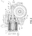
- FIG. 2 is a cross-sectional view taken along line A-A of FIG. 1 .
- the brushless motor 1 is, for example, a drive source for a sunroof mounted on a vehicle.
- the brushless motor 1 includes a motor unit (motor) 2, a deceleration unit 3 for decelerating and outputting the rotation of the motor unit 2, and a controller unit 4 for controlling the drive of the motor unit 2.
- the motor unit 2 in the embodiment is an example of a motor within the scope of claims.
- axial direction refers to the rotary axis direction of a shaft 31 of the motor unit 2
- circumferential direction refers to the circumferential direction of the shaft 31
- radial direction refers to the radial direction of the shaft 31.
- the motor unit 2 includes a motor case 5, a substantially square tubular stator 8 housed in the motor case 5, and a rotor 9 arranged on the radial inner side of the stator 8 and rotatable with respect to the stator 8.
- the motor unit 2 is a so-called brushless motor that does not require a brush to supply electric power to the stator 8.
- the motor case 5 is made of, for example, a material such as aluminum die casting having excellent heat dissipation.
- the motor case 5 includes a first motor case 6 and a second motor case 7 that can be divided in the axial direction.
- the outer shapes of the first motor case 6 and the second motor case 7 are each formed in a bottomed tubular shape.
- the outer shape of the first motor case 6 is formed in, for example, a bottomed square tubular shape.
- the outer shape of the second motor case 7 is formed in, for example, a bottomed tubular shape having a substantially rounded regular hexagonal cross section.
- the outer peripheral surface of the second motor case 7 has six corner portions 7A and six flat portions 7B.
- the first motor case 6 is integrally formed with a gear case 40 so that an end portion 10 is joined to the gear case 40 of the deceleration unit 3.
- a through hole 10a through which the shaft 31 of the rotor 9 can be inserted is formed at substantially the center of the end portion 10 in the radial direction.
- an edge portion 16 for joining the second motor case 7 is formed at an opening portion 6a of the first motor case 6, and an outer flange portion 17 protruding radially outward is formed at an opening portion 7a of the second motor case 7.
- the edge portion 16 and the outer flange portion 17 are butted against each other to form the motor case 5 having an internal space.
- the stator 8 is arranged in the internal space of the motor case 5 so that a part of coils 24 described later is accommodated inside the first motor case 6, and a stator core 20 described later is fitted inside the second motor case 7.
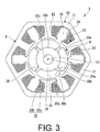
- FIG. 3 is a plan view of the stator 8 and the rotor 9 as viewed from the axial direction.
- the stator 8 includes the stator core 20 in which a tubular core portion 21 is integrally formed with a plurality of (for example, in the present embodiment, six) teeth 22 protruding radially inward from the core portion 21.
- the stator core 20 is formed by laminating a plurality of metal plates in the axial direction. Moreover, the stator core 20 can be formed not only by laminating a plurality of metal plates in the axial direction, but also by, for example, pressure molding soft magnetic powder.
- the core portion 21 is formed in a square tubular shape having a substantially rounded regular hexagonal cross section so as to be fitted inside the second motor case 7. Accordingly, the outer peripheral surface of the core portion 21 has six corner portions and six flat portions.
- the plurality of teeth 22 are arranged so as to protrude radially inward from the portions corresponding to each side of the regular hexagon in the cross section of the core portion 21.
- the teeth 22 include an integrally formed teeth body 22a and a pair of flange portions 22b.
- the teeth body 22a protrudes inward along the radial direction from an inner peripheral surface of the core portion 21.
- the flange portion 22b extends along the circumferential direction from the radial inner end of the teeth body 22a.
- the pair of flange portions 22b are formed so as to extend outward in the circumferential direction from the teeth body 22a.
- a slot 19 is formed between the flange portions 22b which are adjacent in the circumferential direction.
- the inner peripheral surface of the core portion 21 and the teeth 22 are covered with a resin insulator 23.
- the coil 24 is attached so as to be wound around each tooth 22 from the surface of the insulator 23.
- Each coil 24 generates a magnetic field for rotating the rotor 9 by power fed from the controller unit 4.
- the rotor 9 is rotatably arranged on the radial inner side of the stator 8 through a minute gap.
- the rotor 9 includes the shaft 31, a rotor core 32, and four permanent magnets 33.
- the ratio of the number of magnetic poles of the permanent magnets 33 to the number of the slots 19 (the teeth 22) is 4:6.
- the rotor 9 rotates with a rotary axis which is a center line (shaft center) C1 of the shaft 31 as the radial center.
- the shaft 31 is integrally formed with a worm shaft 44 (see FIG. 2 ) that constitutes the deceleration unit 3.
- the shaft 31 rotates around the rotary axis.
- the rotor core 32 is fixed so as to be fitted to the outside of the shaft 31.
- the outer shape of the rotor core 32 is formed in a columnar shape with the shaft 31 as a shaft center C1.
- the rotor core 32 is formed by laminating a plurality of metal plates in the axial direction. Moreover, the rotor core 32 can be formed not only by laminating a plurality of metal plates in the axial direction, but also by, for example, pressure molding soft magnetic powder.
- a through hole 32a penetrating in the axial direction is formed at substantially the center of the rotor core 32 in the radial direction.
- the shaft 31 is pressed into the through hole 32a.
- the shaft 31 may be relatively inserted into the through hole 32a so that the rotor core 32 is fitted to the outside of the shaft 31, and the shaft 31 and the rotor core 32 may be fixed by an adhesive or the like.
- the positions of the arc center of an inner peripheral surface on the radial inner side (that is, an inner peripheral surface of the through hole 32a) and the arc center of an outer peripheral surface 32b on the radial outer side coincide with the position of the shaft center C1 of the shaft 31.
- protrusions 35 are arranged on the outer peripheral surface 32b of the rotor core 32 at equal intervals in the circumferential direction.
- the protrusions 35 are formed so as to protrude outward in the radial direction and extend over the entire rotor core 32 in the axial direction.
- the protrusions 35 are formed in such a manner that two side faces 35a facing each other in the circumferential direction are parallel to the protrusion direction. That is, the protrusions 35 are formed in such a manner that the width dimensions in the circumferential direction are uniform in the protrusion direction.
- round chamfered portions 35b are formed at the corner portions of the protrusions 35 on both sides in the circumferential direction which is outside in the protrusion direction.
- the spaces between two protrusions 35 which are adjacent in the circumferential direction are each configured as a magnet housing portion 36.
- the rotor 9 is a surface magnet (SPM: Surface Permanent Magnet) type rotor having field permanent magnets 33 on the outer peripheral surface 32b of the rotor core 32, as well as an inset type rotor provided with the protrusion 35 protruding outward in the radial direction of the rotor core 32 between the permanent magnets 33 arranged in the circumferential direction.
- SPM Surface Permanent Magnet
- each permanent magnet 33 is arranged in the four magnet housing portions 36 arranged on the outer peripheral surface 32b of the rotor core 32.
- each permanent magnet 33 is fixed to the rotor core 32 by, for example, an adhesive or the like.
- the permanent magnet 33 is, for example, a ferrite magnet, a neodymium bond magnet, a neodymium sintered magnet, or the like.
- the permanent magnets 33 are magnetized so that the orientation of the magnetism (magnetic field) is a parallel orientation along the thickness direction. That is, the orientation of the permanent magnets 33 is a parallel orientation in which the easy magnetization direction is a direction parallel to the radial direction in the center of the permanent magnets 33.
- the permanent magnets 33 which are adjacent in the circumferential direction are arranged in such a manner that the magnetization directions are opposite to each other.
- the four permanent magnets 33 are arranged in such a manner that the magnetic poles are different from each other in the circumferential direction. That is, the permanent magnet 33 having the N pole on the outer peripheral side and the permanent magnet 33 having the S pole on the outer peripheral side are arranged adjacent to each other in the circumferential direction. Accordingly, the protrusion 35 of the rotor core 32 which is arranged between the permanent magnets 33 adjacent to each other in the circumferential direction is located at the boundary (pole boundary) of the magnetic poles.
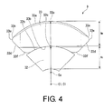
- FIG. 4 is a plan view in which a part of the rotor 9 is shown in an enlarged manner, and is a diagram showing the dimensions of the rotor core 32 and the permanent magnets 33.
- the position of an arc center Ci of an inner peripheral surface 33b on the radial inner side coincides with the position of the shaft center C1 of the shaft 31.
- an arc center Co of an outer peripheral surface 33a on the radial outer side is eccentric with respect to the shaft center C1 of the shaft 31.
- the arc center Co of the outer peripheral surface 33a of the permanent magnet 33 is set closer to the outer peripheral surface 32b of the rotor core 32 than the shaft center C1 in the radial direction passing through the center of the permanent magnet 33.
- the permanent magnet 33 is formed in such a manner that the radial thickness at end portions 33s of the shaft 31 on both sides in the circumferential direction around the shaft center C1 is smaller than the radial thickness in a center 33c of the circumferential direction.
- a gap between the outer peripheral surface 33a of the permanent magnet 33 on the radial outer side and the inner peripheral surface of the teeth 22 is the smallest in the center 33c of the permanent magnet 33 in the circumferential direction, and tends to be larger as separated in the circumferential direction from the center 33c of the circumferential direction.
- the radial thickness of the permanent magnet 33 is formed to be larger than the radial thickness of the rotor core 32.
- a radial thickness Rm in the center 33c of the permanent magnet 33 in the circumferential direction is formed to be larger than a radial thickness Rc in a center 32c of the rotor core 32 in the circumferential direction.
- each surface of the permanent magnet 33 on both sides in the circumferential direction includes a circumferential side face 33d in contact with the protrusion 35, and a connection surface 33e connected to the circumferential side face 33d and to the outer peripheral surface 33a on the radial outer side.
- the circumferential side face 33d is smoothly connected to the inner peripheral surface 33b on the radial inner side via an arc surface 33f.
- the circumferential side face 33d is formed on, for example, a flat surface.
- connection surface 33e is arranged closer to the radial outer side than the circumferential side face 33d, and is connected to the circumferential side face 33d and to the outer peripheral surface 33a.
- connection surface 33e is formed on, for example, a flat surface.
- the connection surface 33e is formed so as to gradually approach the center 33c of the permanent magnets 33 in the circumferential direction as the connection surface 33e is directed outward in the protrusion direction of the protrusion 35.
- the connection surface 33e is formed so as to gradually increase the radial thickness of the permanent magnet 33 as the connection surface 33e is directed outward in the radial direction. That is, the pair of connection surfaces 33e on both sides of the permanent magnet 33 in the circumferential direction are formed so as to gradually decrease the interval in the circumferential direction as the connection surfaces 33e are directed outward in the radial direction.
- connection surfaces 33e are arranged parallel to the easy magnetization direction of the permanent magnets 33.
- FIG. 5 is a plan view in which a part of the rotor 9 is shown in an enlarged manner, and is a diagram showing a length range of the protrusion 35 in the protrusion direction.
- the position of a front end 35t of the protrusion 35 in the protrusion direction is arranged within the area between a center 33g of the circumferential side face 33d of the permanent magnet 33 in the protrusion direction and a crossing ridge portion 33h where the circumferential side face 33d and the connection surface 33e cross. That is, the position of the front end 35t is arranged between a straight line L1 connecting the centers 33g of the adjacent peripheral side faces 33d and a straight line L2 connecting the adjacent crossing ridge portions 33h in the two permanent magnets 33 adjacent to each other so as to sandwich the protrusion 35 from both sides in the circumferential direction.
- a radius R (outer diameter/2) of a circle centered on the shaft center C1 of the shaft 31 and tangent to the front end 35t of the protrusion 35 is equal to or greater than a radius (first radius) R1 of a circle centered on the shaft center C1 and tangent to a straight line L1, and is equal to or smaller than a radius (second radius) R2 of a circle centered on the shaft center C1 and tangent to a straight line L2.
- FIG. 6 is a graph showing an example of the relationship between the length of the protrusion 35 of the rotor 9 and an effective magnetic flux of the permanent magnets 33.
- FIG. 7 is a graph showing an example of the relationship between the length of the protrusion 35 of the rotor 9 and a distortion rate of an induced voltage waveform.
- the length of the protrusion 35 is, for example, the radius R (outer diameter/2) of the circle tangent to the front end 35t of the protrusion 35.
- the fixing stability of the permanent magnets 33 in contact with the protrusion 35 tends to be improved with an increase in the length of the protrusion 35 in the protrusion direction.
- the magnetic flux leaking from the permanent magnet 33 to the protrusion 35 and the distortion of the induced voltage waveform tend to be larger with the increase in the length of the protrusion 35 in the protrusion direction.
- the induced voltage is a voltage induced in each coil 24 by the external drive of the rotor 9 when the power supply for each coil 24 of the stator 8 is de-energized.
- the distortion of the induced voltage waveform is caused by, for example, superimposing harmonics in a sinusoidal induced voltage waveform, and causes an increase in vibration and noise when the brushless motor 1 is driven.
- the distortion rate shown in FIG. 7 is zero when the induced voltage waveform is sinusoidal.
- the distortion of the induced voltage waveform tends to be larger as the radius R corresponding to the front end 35t of the protrusion 35 increases from the first radius R1, and in contrast, the effective magnetic flux for the teeth 22 of the permanent magnets 33 is maximized at the second radius R2.
- the lower limit of the range that defines the length of the protrusion 35 in the protrusion direction is set to, for example, ensure desired fixing stability by the protrusion 35 supporting at least half or more of the portion of the circumferential side face 33d of the permanent magnet 33 in the protrusion direction.
- the upper limit of the range that defines the length of the protrusion 35 in the protrusion direction is set to, for example, maintain the effective magnetic flux of the permanent magnets 33 within a predetermined range including a maximum value Wm while suppressing the distortion of the induced voltage waveform as much as possible below a predetermined allowable level.
- the deceleration unit 3 includes the gear case 40 to which the motor case 5 is attached, and a worm reduction mechanism 41 housed in the gear case 40.
- the gear case 40 is made of, for example, a material such as aluminum die casting having excellent heat dissipation.
- the outer shape of the gear case 40 is formed in, for example, a box shape.
- the gear case 40 has a gear accommodation portion 42 having the worm reduction mechanism 41 accommodated therein.
- an opening portion 43 that allows the through hole 10a of the first motor case 6 to communicate with the gear accommodation portion 42 is formed at a place where the first motor case 6 is integrally formed at an end portion 40a of the gear case 40.
- a guide plate 49 is arranged on the gear case 40.
- the guide plate 49 is arranged to support an output shaft 48 of the worm reduction mechanism 41 to be rotatable.
- the worm reduction mechanism 41 accommodated in the gear accommodation portion 42 is constituted of the worm shaft 44 and a worm wheel 45 meshed with the worm shaft 44.
- the worm shaft 44 is arranged coaxially with the shaft 31 of the motor unit 2. Besides, the worm shaft 44 is rotatably supported by bearings 46 and 47 having both ends arranged on the gear case 40. The end portion of the worm shaft 44 on the motor unit 2 side protrudes to the opening portion 43 of the gear case 40 via the bearing 46. The protruding end portion of the worm shaft 44 is joined to the end portion of the shaft 31 of the motor unit 2, and the worm shaft 44 is integrated with the shaft 31. Moreover, the worm shaft 44 and the shaft 31 may be integrally formed by forming a worm shaft portion and a rotary shaft portion from one base material.
- the worm wheel 45 meshed with the worm shaft 44 is provided with the output shaft 48 in the radial center of the worm wheel 45.
- the output shaft 48 is arranged coaxially with the rotary shaft direction of the worm wheel 45, and is connected to a gear unit 50 protruding to the outside of the gear case 40 via the guide plate 49 of the gear case 40.
- the gear unit 50 is connected to an electrical component (not shown).
- the worm shaft 44 is provided with a rotation position detection portion 60 for detecting the rotation position of the worm shaft 44.
- the rotation position detection portion 60 is connected to the controller unit 4.
- the controller unit 4 that controls the drive of the motor unit 2 has a controller board 62 on which a magnetic detection element or the like is mounted. Besides, the controller board 62 is arranged in the through hole 10a of the first motor case 6.
- the controller board 62 is a so-called epoxy board in which a plurality of conductive patterns (not shown) are formed.
- the terminal portion of the coil 24 drawn from the stator core 20 of the motor unit 2 is connected to the controller board 62, and a terminal 11 arranged in the gear case 40 is electrically connected to the controller board 62.
- a power module (not shown) including a switching element such as a field effect transistor (FET) that controls the current supplied to the coil 24 is also mounted on the controller board 62.
- a capacitor (not shown) for smoothing the voltage applied to the controller board 62 or the like is mounted on the controller board 62.
- the terminal 11 is formed in a manner that the terminal 11 can be fitted with a connector extending from an external power supply (not shown). Besides, the controller board 62 is electrically connected to the terminal 11. Accordingly, the electric power of the external power supply is supplied to the controller board 62.
- the electric power supplied to the controller board 62 via the terminal 11 is selectively supplied to each coil 24 of the motor unit 2 via the power module (not shown).
- each coil 24 forms a predetermined interlinkage magnetic flux in the stator 8 (the teeth 22).
- a magnetic attractive force or repulsive force is generated between the interlinkage magnetic flux and the effective magnetic flux formed by the permanent magnets 33 of the rotor 9.
- the protrusion direction of the protrusion 35 of the rotor core 32 is set as a direction in which the interlinkage magnetic flux from the stator 8 (the teeth 22) flows easily, and the protrusion 35 generates a reluctance torque that rotates the rotor core 32 so as to reduce the magnetic resistance (reluctance) of the magnetic path of the interlinkage magnetic flux.
- the magnet torque and reluctance torque continuously rotate the rotor 9.
- the rotation of the rotor 9 is transmitted to the worm shaft 44 integrated with the shaft 31 and further transmitted to the worm wheel 45 meshed with the worm shaft 44. Then, the rotation of the worm wheel 45 is transmitted to the output shaft 48 connected to the worm wheel 45, and the output shaft 48 drives a desired electrical component.
- the detection signal of the rotation position of the worm wheel 45 detected by the magnetic detection element mounted on the controller board 62 and the rotation position detection portion 60 is output to an external device (not shown).
- the external device is, for example, a software function unit that functions by executing a predetermined program by a processor such as a central processing unit (CPU).
- the software function unit is an electronic control unit (ECU) equipped with a processor such as a CPU, a read only memory (ROM) for storing programs, a random access memory (RAM) for temporarily storing data, an electronic circuit such as a timer, and the like.
- the external device may be an integrated circuit such as a large scale integration (LSI).
- LSI large scale integration
- the external device controls the switching timing of the switching element or the like of the power module (not shown) based on the detection signal of the rotation position of the worm wheel 45 and controls the drive of the motor unit 2. Moreover, the output of the drive signal of the power module and the drive control of the motor unit 2 may be executed by the controller unit 4 instead of the external device (not shown).
- the protrusion 35 of the rotor core 32 can support more than half of the region on the circumferential side faces 33d of the permanent magnets 33 in the protrusion direction. Accordingly, desired fixing stability (for example, seating property or the like) of the permanent magnets 33 on the outer peripheral surface 32b of the rotor core 32 can be ensured.
- the desired fixing stability of the permanent magnets 33 can be ensured by the protrusion 35 even when the radial thickness of the permanent magnets 33 is formed to be relatively larger than the radial thickness of the rotor core 32.
- the protrusion 35 is formed so as not to protrude closer to the outside than the crossing ridge portion 33h where the circumferential side face 33d and the connection surface 33e of the permanent magnets 33 cross in the protrusion direction. Accordingly, the magnetic flux leaking from the permanent magnet 33 to the protrusion 35 and the distortion of the induced voltage waveform can be suppressed as much as possible below a predetermined allowable level, and the effective magnetic flux of the permanent magnets 33 can be maintained within a predetermined range including a maximum value.
- the orientation of the permanent magnets 33 is a parallel orientation, and the easy magnetization direction in the vicinity of the end portions 33s on both sides in the circumferential direction of the permanent magnets 33 adjacent to the protrusion 35 intersects with the protrusion direction of the protrusion 35. Accordingly, formation of a magnetic path by the magnetic flux leaking from the permanent magnet 33 to the protrusion 35 is suppressed, and thus an increase in the leakage flux can be suppressed.
- FIG. 8 is a plan view showing an example of the flow of magnetic flux to the protrusion 35 of the rotor 9 in the embodiment.
- FIG. 9 is a plan view showing an example of the flow of magnetic flux to the protrusion 35 of the rotor 9 in a comparative example of the embodiment.
- the orientation of the permanent magnets 33 is a radial orientation in which an easy magnetization direction D is radial along the radial direction of the permanent magnets 33.
- the position of the front end 35t of the protrusion 35 in the protrusion direction is arranged closer to the outside than the crossing ridge portion 33h of the permanent magnets 33. Accordingly, a magnetic path generated by the magnetic flux leaking from the permanent magnet 33 to the protrusion 35 is easily formed between the end portions 33s of the permanent magnets 33 on both sides in the circumferential direction and the protrusion 35.
- the orientation of the permanent magnets 33 is a parallel orientation.
- the position of the front end 35t of the protrusion 35 in the protrusion direction is arranged within the area between the center 33g of the circumferential side face 33d of the permanent magnet 33 and the crossing ridge portion 33h. Accordingly, the formation of the magnetic path by the magnetic flux leaking from the permanent magnet 33 to the protrusion 35 is suppressed as compared with the comparative example.
- connection surface 33e of the permanent magnet 33 is parallel to the easy magnetization direction of the permanent magnet 33 which is a parallel orientation. Accordingly, the distortion of the induced voltage waveform can be suppressed.
- the brushless motor 1 of the present embodiment includes the rotor 9 that ensures the desired effective magnetic flux of the permanent magnets 33 and suppresses the magnetic flux leaking from the permanent magnet 33 to the protrusion 35 and the distortion of the induced voltage waveform. Accordingly, it is possible to ensure a desired output while suppressing an increase in cogging torque and torque ripple due to the magnetic field distortion and an increase in vibration and noise when the brushless motor 1 is driven.
- the arc center Co of the outer peripheral surface 33a of the permanent magnets 33 on the radial outer side is eccentric with respect to the shaft center C1 of the shaft 31, but the present invention is not limited thereto. Similar to the arc center Ci of the inner peripheral surface 33b on the radial inner side, the arc center Co of the outer peripheral surface 33a of the permanent magnets 33 may coincide with the position of the shaft center C1 of the shaft 31.
- the brushless motor 1 is a drive source for a sunroof mounted on a vehicle, but the present invention is not limited thereto.
- the brushless motor 1 may be a drive source for various electrical components (for example, a power window, an electric seat, a wiper, and the like) mounted on a vehicle or a drive source mounted on various devices other than the vehicle.
Landscapes
- Engineering & Computer Science (AREA)
- Power Engineering (AREA)
- Permanent Field Magnets Of Synchronous Machinery (AREA)
- Iron Core Of Rotating Electric Machines (AREA)
Abstract
Description
- The present invention relates to a rotor, a motor and a brushless motor.
- Conventionally, as a surface magnet (SPM: Surface Permanent Magnet) type rotor having field permanent magnets on the surface of a rotor core, an inset type rotor (for example, see Patent literature 1) is known which is provided with a protrusion protruding outward in the radial direction of the rotor core between permanent magnets arranged in the circumferential direction. In this rotor, the protrusion of the rotor core regulates rotational movement of the permanent magnets on the surface of the rotor core.
- Patent literature 1:
International Publication No. WO2015/102047 - Meanwhile, in the rotor as described above, fixing stability of the permanent magnets tends to be improved with an increase in the protrusion length of the protrusion in the radial direction. However, magnetic field distortion tends to be larger with an increase in the protrusion length of a protrusion made of a magnetic material in the radial direction. Therefore, the magnetic field distortion may cause an increase in cogging torque and torque ripple, and an increase in noise and vibration of a motor.
- Therefore, an object of the present invention is to provide a rotor, a motor and a brushless motor which can suppress increased magnetic field distortion while maintaining fixing stability of magnets on the surface of a rotor.
- The present invention adopts the following approach to solve the above problems.
- That is, a rotor of the present invention includes: a shaft rotating around a rotary axis, a rotor core that holds the shaft and rotates with the rotary axis as a radial center, a magnet arranged on an outer peripheral surface of the rotor core, and a protrusion protruding radially outward between the magnets which are adjacent in a circumferential direction on the outer peripheral surface of the rotor core. An orientation of the magnets is a parallel orientation in which an easy magnetization direction is parallel to a radial direction of a center of the magnets. The magnets include a circumferential side face that contacts the protrusion in the circumferential direction, and a connection surface that is connected to the circumferential side face and to an outer peripheral surface on a radial outer side, and are formed so as to gradually approach the center of the magnets in the circumferential direction as directed outward in the protrusion direction of the protrusion. The position of a front end of the protrusion in the protrusion direction is arranged within an area between a center of the circumferential side face in the protrusion direction and a crossing ridge portion where the circumferential side face and the connection surface cross.
- According to the above configuration, the protrusion can support more than half of the region on the circumferential side face of the magnet in the protrusion direction. Accordingly, desired fixing stability (for example, seating property or the like) of the magnet on the outer peripheral surface of the rotor core can be ensured.
- In addition, the protrusion is formed so as not to protrude closer to the outside than the crossing ridge portion where the circumferential side face and the connection surface of the magnet cross in the protrusion direction. Accordingly, a magnetic flux leaking from the magnet to the protrusion and distortion of an induced voltage waveform can be suppressed as much as possible below a predetermined allowable level, and an effective magnetic flux of the permanent magnets can be maintained within a predetermined range including a maximum value.
- Besides, the orientation of the magnets is a parallel orientation, and the easy magnetization direction in the vicinity of the circumferential end portion of the magnet adjacent to the protrusion intersects with the protrusion direction of the protrusion. Accordingly, formation of a magnetic path by the magnetic flux leaking from the magnet to the protrusion is suppressed, and an increase in the leakage flux can be suppressed.
- In addition, in the rotor of the present invention, it is preferable that the connection surfaces is parallel to the easy magnetization direction of the magnets.
- According to the above configuration, the connection surfaces are parallel to the easy magnetization direction of the magnets which is a parallel orientation. Accordingly, the distortion of the induced voltage waveform can be suppressed.
- Besides, in the rotor of the present invention, it is preferable that a radial thickness of the magnets is formed to be larger than a radial thickness of the rotor core.
- According to the above configuration, the desired fixing stability of the magnets can be ensured by the protrusion even when the radial thickness of the magnet is formed to be relatively larger than the radial thickness of the rotor core.
- A motor of the present invention includes: a stator having an annular stator core and a plurality of teeth protruding radially inward from an inner peripheral surface of the stator core, a coil attached to the teeth, and the rotor arranged on a radial inner side with respect to the plurality of teeth.
- According to the above configuration, the motor includes a rotor that ensures a desired effective magnetic flux of the magnets and suppresses the magnetic flux leaking from the magnet to the protrusion and the distortion of the induced voltage waveform. Accordingly, it is possible to ensure a desired output while suppressing the increase in cogging torque and torque ripple due to the magnetic field distortion and the increase in vibration and noise when the motor is driven.
- A brushless motor of the present invention includes the motor.
- According to the above configuration, the desired output of the brushless motor can be ensured, and the increase in vibration and noise during driving can be suppressed.
- According to the present invention, the fixing stability of the magnets in the rotor can be ensured, and the increased magnetic field distortion can be suppressed.
-
-
FIG. 1 is a perspective view of a brushless motor according to an embodiment of the present invention. -
FIG. 2 is a cross-sectional view of the brushless motor according to an embodiment of the present invention along line A-A ofFIG. 1 . -
FIG. 3 is a plan view of a stator and a rotor according to an embodiment of the present invention as viewed from the axial direction. -
FIG. 4 is a plan view in which a part of the rotor according to an embodiment of the present invention is shown in an enlarged manner, and is a diagram showing the dimensions of a rotor core and permanent magnets. -
FIG. 5 is a plan view in which a part of the rotor according to an embodiment of the present invention is shown in an enlarged manner, and is a diagram showing a length range of a protrusion in the protrusion direction. -
FIG. 6 is a graph showing an example of the relationship between the length of the protrusion of the rotor according to an embodiment of the present invention and an effective magnetic flux of the permanent magnets. -
FIG. 7 is a graph showing an example of the relationship between the length of the protrusion of the rotor according to an embodiment of the present invention and a distortion rate of an induced voltage. -
FIG. 8 is a plan view showing an example of the flow of magnetic flux to the protrusion of the rotor according to an embodiment of the present invention. -
FIG. 9 is a plan view showing an example of the flow of magnetic flux to the protrusion of the rotor in a comparative example of an embodiment of the present invention. - Hereinafter, a rotor, a motor, and a brushless motor according to an embodiment of the present invention are described with reference to the accompanying drawings.
-
FIG. 1 is a perspective view of a brushless motor 1.FIG. 2 is a cross-sectional view taken along line A-A ofFIG. 1 . - As shown in
FIG. 1 andFIG. 2 , the brushless motor 1 is, for example, a drive source for a sunroof mounted on a vehicle. The brushless motor 1 includes a motor unit (motor) 2, a deceleration unit 3 for decelerating and outputting the rotation of themotor unit 2, and acontroller unit 4 for controlling the drive of themotor unit 2. Moreover, themotor unit 2 in the embodiment is an example of a motor within the scope of claims. - Moreover, in the following description, the term "axial direction" refers to the rotary axis direction of a
shaft 31 of themotor unit 2, the term "circumferential direction" refers to the circumferential direction of theshaft 31, and the term "radial direction" refers to the radial direction of theshaft 31. - The
motor unit 2 includes amotor case 5, a substantially squaretubular stator 8 housed in themotor case 5, and arotor 9 arranged on the radial inner side of thestator 8 and rotatable with respect to thestator 8. Themotor unit 2 is a so-called brushless motor that does not require a brush to supply electric power to thestator 8. - The
motor case 5 is made of, for example, a material such as aluminum die casting having excellent heat dissipation. Themotor case 5 includes a first motor case 6 and a second motor case 7 that can be divided in the axial direction. The outer shapes of the first motor case 6 and the second motor case 7 are each formed in a bottomed tubular shape. The outer shape of the first motor case 6 is formed in, for example, a bottomed square tubular shape. The outer shape of the second motor case 7 is formed in, for example, a bottomed tubular shape having a substantially rounded regular hexagonal cross section. The outer peripheral surface of the second motor case 7 has sixcorner portions 7A and sixflat portions 7B. - The first motor case 6 is integrally formed with a
gear case 40 so that anend portion 10 is joined to thegear case 40 of the deceleration unit 3. A throughhole 10a through which theshaft 31 of therotor 9 can be inserted is formed at substantially the center of theend portion 10 in the radial direction. - In addition, an
edge portion 16 for joining the second motor case 7 is formed at anopening portion 6a of the first motor case 6, and anouter flange portion 17 protruding radially outward is formed at anopening portion 7a of the second motor case 7. Theedge portion 16 and theouter flange portion 17 are butted against each other to form themotor case 5 having an internal space. Besides, thestator 8 is arranged in the internal space of themotor case 5 so that a part ofcoils 24 described later is accommodated inside the first motor case 6, and astator core 20 described later is fitted inside the second motor case 7. -
FIG. 3 is a plan view of thestator 8 and therotor 9 as viewed from the axial direction. As shown inFIG. 2 andFIG. 3 , thestator 8 includes thestator core 20 in which atubular core portion 21 is integrally formed with a plurality of (for example, in the present embodiment, six)teeth 22 protruding radially inward from thecore portion 21. - The
stator core 20 is formed by laminating a plurality of metal plates in the axial direction. Moreover, thestator core 20 can be formed not only by laminating a plurality of metal plates in the axial direction, but also by, for example, pressure molding soft magnetic powder. - The
core portion 21 is formed in a square tubular shape having a substantially rounded regular hexagonal cross section so as to be fitted inside the second motor case 7. Accordingly, the outer peripheral surface of thecore portion 21 has six corner portions and six flat portions. The plurality ofteeth 22 are arranged so as to protrude radially inward from the portions corresponding to each side of the regular hexagon in the cross section of thecore portion 21. - The
teeth 22 include an integrally formedteeth body 22a and a pair offlange portions 22b. Theteeth body 22a protrudes inward along the radial direction from an inner peripheral surface of thecore portion 21. Theflange portion 22b extends along the circumferential direction from the radial inner end of theteeth body 22a. The pair offlange portions 22b are formed so as to extend outward in the circumferential direction from theteeth body 22a. Besides, aslot 19 is formed between theflange portions 22b which are adjacent in the circumferential direction. - In addition, the inner peripheral surface of the
core portion 21 and theteeth 22 are covered with aresin insulator 23. Thecoil 24 is attached so as to be wound around eachtooth 22 from the surface of theinsulator 23. Eachcoil 24 generates a magnetic field for rotating therotor 9 by power fed from thecontroller unit 4. - The
rotor 9 is rotatably arranged on the radial inner side of thestator 8 through a minute gap. Therotor 9 includes theshaft 31, arotor core 32, and fourpermanent magnets 33. Thus, in themotor unit 2, for example, the ratio of the number of magnetic poles of thepermanent magnets 33 to the number of the slots 19 (the teeth 22) is 4:6. - The
rotor 9 rotates with a rotary axis which is a center line (shaft center) C1 of theshaft 31 as the radial center. - The
shaft 31 is integrally formed with a worm shaft 44 (seeFIG. 2 ) that constitutes the deceleration unit 3. Theshaft 31 rotates around the rotary axis. - The
rotor core 32 is fixed so as to be fitted to the outside of theshaft 31. The outer shape of therotor core 32 is formed in a columnar shape with theshaft 31 as a shaft center C1. - The
rotor core 32 is formed by laminating a plurality of metal plates in the axial direction. Moreover, therotor core 32 can be formed not only by laminating a plurality of metal plates in the axial direction, but also by, for example, pressure molding soft magnetic powder. - Besides, a through
hole 32a penetrating in the axial direction is formed at substantially the center of therotor core 32 in the radial direction. Theshaft 31 is pressed into the throughhole 32a. Moreover, theshaft 31 may be relatively inserted into the throughhole 32a so that therotor core 32 is fitted to the outside of theshaft 31, and theshaft 31 and therotor core 32 may be fixed by an adhesive or the like. - In the
rotor core 32, the positions of the arc center of an inner peripheral surface on the radial inner side (that is, an inner peripheral surface of the throughhole 32a) and the arc center of an outerperipheral surface 32b on the radial outer side coincide with the position of the shaft center C1 of theshaft 31. - Furthermore, four
protrusions 35 are arranged on the outerperipheral surface 32b of therotor core 32 at equal intervals in the circumferential direction. Theprotrusions 35 are formed so as to protrude outward in the radial direction and extend over theentire rotor core 32 in the axial direction. - In addition, the
protrusions 35 are formed in such a manner that two side faces 35a facing each other in the circumferential direction are parallel to the protrusion direction. That is, theprotrusions 35 are formed in such a manner that the width dimensions in the circumferential direction are uniform in the protrusion direction. - Furthermore, round chamfered
portions 35b are formed at the corner portions of theprotrusions 35 on both sides in the circumferential direction which is outside in the protrusion direction. - On the outer
peripheral surface 32b of therotor core 32 formed in this way, the spaces between twoprotrusions 35 which are adjacent in the circumferential direction are each configured as amagnet housing portion 36. - That is, the
rotor 9 is a surface magnet (SPM: Surface Permanent Magnet) type rotor having fieldpermanent magnets 33 on the outerperipheral surface 32b of therotor core 32, as well as an inset type rotor provided with theprotrusion 35 protruding outward in the radial direction of therotor core 32 between thepermanent magnets 33 arranged in the circumferential direction. - The four
permanent magnets 33 are arranged in the fourmagnet housing portions 36 arranged on the outerperipheral surface 32b of therotor core 32. In themagnet housing portion 36, eachpermanent magnet 33 is fixed to therotor core 32 by, for example, an adhesive or the like. - The
permanent magnet 33 is, for example, a ferrite magnet, a neodymium bond magnet, a neodymium sintered magnet, or the like. - The
permanent magnets 33 are magnetized so that the orientation of the magnetism (magnetic field) is a parallel orientation along the thickness direction. That is, the orientation of thepermanent magnets 33 is a parallel orientation in which the easy magnetization direction is a direction parallel to the radial direction in the center of thepermanent magnets 33. - Besides, the
permanent magnets 33 which are adjacent in the circumferential direction are arranged in such a manner that the magnetization directions are opposite to each other. The fourpermanent magnets 33 are arranged in such a manner that the magnetic poles are different from each other in the circumferential direction. That is, thepermanent magnet 33 having the N pole on the outer peripheral side and thepermanent magnet 33 having the S pole on the outer peripheral side are arranged adjacent to each other in the circumferential direction. Accordingly, theprotrusion 35 of therotor core 32 which is arranged between thepermanent magnets 33 adjacent to each other in the circumferential direction is located at the boundary (pole boundary) of the magnetic poles. -
FIG. 4 is a plan view in which a part of therotor 9 is shown in an enlarged manner, and is a diagram showing the dimensions of therotor core 32 and thepermanent magnets 33. - In the
permanent magnets 33, the position of an arc center Ci of an innerperipheral surface 33b on the radial inner side coincides with the position of the shaft center C1 of theshaft 31. - In the
permanent magnets 33, an arc center Co of an outerperipheral surface 33a on the radial outer side is eccentric with respect to the shaft center C1 of theshaft 31. Specifically, the arc center Co of the outerperipheral surface 33a of thepermanent magnet 33 is set closer to the outerperipheral surface 32b of therotor core 32 than the shaft center C1 in the radial direction passing through the center of thepermanent magnet 33. Accordingly, thepermanent magnet 33 is formed in such a manner that the radial thickness atend portions 33s of theshaft 31 on both sides in the circumferential direction around the shaft center C1 is smaller than the radial thickness in acenter 33c of the circumferential direction. As a result, a gap between the outerperipheral surface 33a of thepermanent magnet 33 on the radial outer side and the inner peripheral surface of theteeth 22 is the smallest in thecenter 33c of thepermanent magnet 33 in the circumferential direction, and tends to be larger as separated in the circumferential direction from thecenter 33c of the circumferential direction. - The radial thickness of the
permanent magnet 33 is formed to be larger than the radial thickness of therotor core 32. For example, a radial thickness Rm in thecenter 33c of thepermanent magnet 33 in the circumferential direction is formed to be larger than a radial thickness Rc in acenter 32c of therotor core 32 in the circumferential direction. - Almost the entire inner
peripheral surface 33b of thepermanent magnet 33 is in contact with the outerperipheral surface 32b of therotor core 32. In addition, each surface of thepermanent magnet 33 on both sides in the circumferential direction includes acircumferential side face 33d in contact with theprotrusion 35, and aconnection surface 33e connected to thecircumferential side face 33d and to the outerperipheral surface 33a on the radial outer side. - The
circumferential side face 33d is smoothly connected to the innerperipheral surface 33b on the radial inner side via anarc surface 33f. Thecircumferential side face 33d is formed on, for example, a flat surface. - The
connection surface 33e is arranged closer to the radial outer side than thecircumferential side face 33d, and is connected to thecircumferential side face 33d and to the outerperipheral surface 33a. - The
connection surface 33e is formed on, for example, a flat surface. Theconnection surface 33e is formed so as to gradually approach thecenter 33c of thepermanent magnets 33 in the circumferential direction as theconnection surface 33e is directed outward in the protrusion direction of theprotrusion 35. For example, theconnection surface 33e is formed so as to gradually increase the radial thickness of thepermanent magnet 33 as theconnection surface 33e is directed outward in the radial direction. That is, the pair ofconnection surfaces 33e on both sides of thepermanent magnet 33 in the circumferential direction are formed so as to gradually decrease the interval in the circumferential direction as the connection surfaces 33e are directed outward in the radial direction. - Besides, the connection surfaces 33e are arranged parallel to the easy magnetization direction of the
permanent magnets 33. -
FIG. 5 is a plan view in which a part of therotor 9 is shown in an enlarged manner, and is a diagram showing a length range of theprotrusion 35 in the protrusion direction. - The position of a
front end 35t of theprotrusion 35 in the protrusion direction is arranged within the area between acenter 33g of thecircumferential side face 33d of thepermanent magnet 33 in the protrusion direction and acrossing ridge portion 33h where thecircumferential side face 33d and theconnection surface 33e cross. That is, the position of thefront end 35t is arranged between a straight line L1 connecting thecenters 33g of the adjacent peripheral side faces 33d and a straight line L2 connecting the adjacentcrossing ridge portions 33h in the twopermanent magnets 33 adjacent to each other so as to sandwich theprotrusion 35 from both sides in the circumferential direction. - For example, a radius R (outer diameter/2) of a circle centered on the shaft center C1 of the
shaft 31 and tangent to thefront end 35t of theprotrusion 35 is equal to or greater than a radius (first radius) R1 of a circle centered on the shaft center C1 and tangent to a straight line L1, and is equal to or smaller than a radius (second radius) R2 of a circle centered on the shaft center C1 and tangent to a straight line L2. -
FIG. 6 is a graph showing an example of the relationship between the length of theprotrusion 35 of therotor 9 and an effective magnetic flux of thepermanent magnets 33.FIG. 7 is a graph showing an example of the relationship between the length of theprotrusion 35 of therotor 9 and a distortion rate of an induced voltage waveform. Moreover, inFIG. 6 and FIG. 7 , the length of theprotrusion 35 is, for example, the radius R (outer diameter/2) of the circle tangent to thefront end 35t of theprotrusion 35. - In the
rotor 9, the fixing stability of thepermanent magnets 33 in contact with the protrusion 35 (for example, the seating property for themagnet housing portion 36 or the like) tends to be improved with an increase in the length of theprotrusion 35 in the protrusion direction. On the other hand, the magnetic flux leaking from thepermanent magnet 33 to theprotrusion 35 and the distortion of the induced voltage waveform tend to be larger with the increase in the length of theprotrusion 35 in the protrusion direction. Moreover, the induced voltage is a voltage induced in eachcoil 24 by the external drive of therotor 9 when the power supply for eachcoil 24 of thestator 8 is de-energized. The distortion of the induced voltage waveform is caused by, for example, superimposing harmonics in a sinusoidal induced voltage waveform, and causes an increase in vibration and noise when the brushless motor 1 is driven. The distortion rate shown inFIG. 7 is zero when the induced voltage waveform is sinusoidal. - As shown in
FIG. 6 and FIG. 7 , the distortion of the induced voltage waveform tends to be larger as the radius R corresponding to thefront end 35t of theprotrusion 35 increases from the first radius R1, and in contrast, the effective magnetic flux for theteeth 22 of thepermanent magnets 33 is maximized at the second radius R2. - That is, the lower limit of the range that defines the length of the
protrusion 35 in the protrusion direction is set to, for example, ensure desired fixing stability by theprotrusion 35 supporting at least half or more of the portion of thecircumferential side face 33d of thepermanent magnet 33 in the protrusion direction. In addition, the upper limit of the range that defines the length of theprotrusion 35 in the protrusion direction is set to, for example, maintain the effective magnetic flux of thepermanent magnets 33 within a predetermined range including a maximum value Wm while suppressing the distortion of the induced voltage waveform as much as possible below a predetermined allowable level. - Returning to
FIG. 1 andFIG. 2 , the deceleration unit 3 includes thegear case 40 to which themotor case 5 is attached, and aworm reduction mechanism 41 housed in thegear case 40. - The
gear case 40 is made of, for example, a material such as aluminum die casting having excellent heat dissipation. The outer shape of thegear case 40 is formed in, for example, a box shape. Thegear case 40 has agear accommodation portion 42 having theworm reduction mechanism 41 accommodated therein. In addition, an openingportion 43 that allows the throughhole 10a of the first motor case 6 to communicate with thegear accommodation portion 42 is formed at a place where the first motor case 6 is integrally formed at anend portion 40a of thegear case 40. - In addition, a
guide plate 49 is arranged on thegear case 40. Theguide plate 49 is arranged to support anoutput shaft 48 of theworm reduction mechanism 41 to be rotatable. - The
worm reduction mechanism 41 accommodated in thegear accommodation portion 42 is constituted of theworm shaft 44 and aworm wheel 45 meshed with theworm shaft 44. - The
worm shaft 44 is arranged coaxially with theshaft 31 of themotor unit 2. Besides, theworm shaft 44 is rotatably supported bybearings gear case 40. The end portion of theworm shaft 44 on themotor unit 2 side protrudes to the openingportion 43 of thegear case 40 via thebearing 46. The protruding end portion of theworm shaft 44 is joined to the end portion of theshaft 31 of themotor unit 2, and theworm shaft 44 is integrated with theshaft 31. Moreover, theworm shaft 44 and theshaft 31 may be integrally formed by forming a worm shaft portion and a rotary shaft portion from one base material. - The
worm wheel 45 meshed with theworm shaft 44 is provided with theoutput shaft 48 in the radial center of theworm wheel 45. Theoutput shaft 48 is arranged coaxially with the rotary shaft direction of theworm wheel 45, and is connected to agear unit 50 protruding to the outside of thegear case 40 via theguide plate 49 of thegear case 40. Thegear unit 50 is connected to an electrical component (not shown). - In addition, the
worm shaft 44 is provided with a rotationposition detection portion 60 for detecting the rotation position of theworm shaft 44. The rotationposition detection portion 60 is connected to thecontroller unit 4. - The
controller unit 4 that controls the drive of themotor unit 2 has acontroller board 62 on which a magnetic detection element or the like is mounted. Besides, thecontroller board 62 is arranged in the throughhole 10a of the first motor case 6. - The
controller board 62 is a so-called epoxy board in which a plurality of conductive patterns (not shown) are formed. The terminal portion of thecoil 24 drawn from thestator core 20 of themotor unit 2 is connected to thecontroller board 62, and a terminal 11 arranged in thegear case 40 is electrically connected to thecontroller board 62. In addition, in addition to the magnetic detection element, a power module (not shown) including a switching element such as a field effect transistor (FET) that controls the current supplied to thecoil 24 is also mounted on thecontroller board 62. Furthermore, a capacitor (not shown) for smoothing the voltage applied to thecontroller board 62 or the like is mounted on thecontroller board 62. - The terminal 11 is formed in a manner that the terminal 11 can be fitted with a connector extending from an external power supply (not shown). Besides, the
controller board 62 is electrically connected to the terminal 11. Accordingly, the electric power of the external power supply is supplied to thecontroller board 62. - Next, the operation of the brushless motor 1 is described.
- In the brushless motor 1, the electric power supplied to the
controller board 62 via the terminal 11 is selectively supplied to eachcoil 24 of themotor unit 2 via the power module (not shown). - Then, the current flowing through each
coil 24 forms a predetermined interlinkage magnetic flux in the stator 8 (the teeth 22). A magnetic attractive force or repulsive force (magnet torque) is generated between the interlinkage magnetic flux and the effective magnetic flux formed by thepermanent magnets 33 of therotor 9. - Besides, the protrusion direction of the
protrusion 35 of therotor core 32 is set as a direction in which the interlinkage magnetic flux from the stator 8 (the teeth 22) flows easily, and theprotrusion 35 generates a reluctance torque that rotates therotor core 32 so as to reduce the magnetic resistance (reluctance) of the magnetic path of the interlinkage magnetic flux. - The magnet torque and reluctance torque continuously rotate the
rotor 9. - The rotation of the
rotor 9 is transmitted to theworm shaft 44 integrated with theshaft 31 and further transmitted to theworm wheel 45 meshed with theworm shaft 44. Then, the rotation of theworm wheel 45 is transmitted to theoutput shaft 48 connected to theworm wheel 45, and theoutput shaft 48 drives a desired electrical component. - In addition, the detection signal of the rotation position of the
worm wheel 45 detected by the magnetic detection element mounted on thecontroller board 62 and the rotationposition detection portion 60 is output to an external device (not shown). The external device (not shown) is, for example, a software function unit that functions by executing a predetermined program by a processor such as a central processing unit (CPU). The software function unit is an electronic control unit (ECU) equipped with a processor such as a CPU, a read only memory (ROM) for storing programs, a random access memory (RAM) for temporarily storing data, an electronic circuit such as a timer, and the like. In addition, at least a part of the external device (not shown) may be an integrated circuit such as a large scale integration (LSI). The external device (not shown) controls the switching timing of the switching element or the like of the power module (not shown) based on the detection signal of the rotation position of theworm wheel 45 and controls the drive of themotor unit 2. Moreover, the output of the drive signal of the power module and the drive control of themotor unit 2 may be executed by thecontroller unit 4 instead of the external device (not shown). - As described above, according to the
rotor 9 of the present embodiment, theprotrusion 35 of therotor core 32 can support more than half of the region on the circumferential side faces 33d of thepermanent magnets 33 in the protrusion direction. Accordingly, desired fixing stability (for example, seating property or the like) of thepermanent magnets 33 on the outerperipheral surface 32b of therotor core 32 can be ensured. - For example, the desired fixing stability of the
permanent magnets 33 can be ensured by theprotrusion 35 even when the radial thickness of thepermanent magnets 33 is formed to be relatively larger than the radial thickness of therotor core 32. - In addition, the
protrusion 35 is formed so as not to protrude closer to the outside than the crossingridge portion 33h where thecircumferential side face 33d and theconnection surface 33e of thepermanent magnets 33 cross in the protrusion direction. Accordingly, the magnetic flux leaking from thepermanent magnet 33 to theprotrusion 35 and the distortion of the induced voltage waveform can be suppressed as much as possible below a predetermined allowable level, and the effective magnetic flux of thepermanent magnets 33 can be maintained within a predetermined range including a maximum value. - Besides, the orientation of the
permanent magnets 33 is a parallel orientation, and the easy magnetization direction in the vicinity of theend portions 33s on both sides in the circumferential direction of thepermanent magnets 33 adjacent to theprotrusion 35 intersects with the protrusion direction of theprotrusion 35. Accordingly, formation of a magnetic path by the magnetic flux leaking from thepermanent magnet 33 to theprotrusion 35 is suppressed, and thus an increase in the leakage flux can be suppressed. -
FIG. 8 is a plan view showing an example of the flow of magnetic flux to theprotrusion 35 of therotor 9 in the embodiment.FIG. 9 is a plan view showing an example of the flow of magnetic flux to theprotrusion 35 of therotor 9 in a comparative example of the embodiment. - In the comparative example shown in
FIG. 9 , the orientation of thepermanent magnets 33 is a radial orientation in which an easy magnetization direction D is radial along the radial direction of thepermanent magnets 33. In addition, the position of thefront end 35t of theprotrusion 35 in the protrusion direction is arranged closer to the outside than the crossingridge portion 33h of thepermanent magnets 33. Accordingly, a magnetic path generated by the magnetic flux leaking from thepermanent magnet 33 to theprotrusion 35 is easily formed between theend portions 33s of thepermanent magnets 33 on both sides in the circumferential direction and theprotrusion 35. - On the other hand, in the embodiment shown in
FIG. 8 , the orientation of thepermanent magnets 33 is a parallel orientation. In addition, the position of thefront end 35t of theprotrusion 35 in the protrusion direction is arranged within the area between thecenter 33g of thecircumferential side face 33d of thepermanent magnet 33 and thecrossing ridge portion 33h. Accordingly, the formation of the magnetic path by the magnetic flux leaking from thepermanent magnet 33 to theprotrusion 35 is suppressed as compared with the comparative example. - Besides, the
connection surface 33e of thepermanent magnet 33 is parallel to the easy magnetization direction of thepermanent magnet 33 which is a parallel orientation. Accordingly, the distortion of the induced voltage waveform can be suppressed. - In addition, the brushless motor 1 of the present embodiment includes the
rotor 9 that ensures the desired effective magnetic flux of thepermanent magnets 33 and suppresses the magnetic flux leaking from thepermanent magnet 33 to theprotrusion 35 and the distortion of the induced voltage waveform. Accordingly, it is possible to ensure a desired output while suppressing an increase in cogging torque and torque ripple due to the magnetic field distortion and an increase in vibration and noise when the brushless motor 1 is driven. - Hereinafter, a variation example of the embodiment is described.
- In the embodiment described above, the arc center Co of the outer
peripheral surface 33a of thepermanent magnets 33 on the radial outer side is eccentric with respect to the shaft center C1 of theshaft 31, but the present invention is not limited thereto. Similar to the arc center Ci of the innerperipheral surface 33b on the radial inner side, the arc center Co of the outerperipheral surface 33a of thepermanent magnets 33 may coincide with the position of the shaft center C1 of theshaft 31. - Moreover, in the embodiment described above, the brushless motor 1 is a drive source for a sunroof mounted on a vehicle, but the present invention is not limited thereto. For example, the brushless motor 1 may be a drive source for various electrical components (for example, a power window, an electric seat, a wiper, and the like) mounted on a vehicle or a drive source mounted on various devices other than the vehicle.
- The embodiments of the present invention are illustrative and are not intended to limit the scope of the invention. The embodiments can be implemented in various other forms, and various omissions, replacements, and changes can be made without departing from the gist of the invention. These embodiments and variations thereof are included in the scope and gist of the invention as well as in the scope equivalent to that of the invention set forth in the claims.
-
- 1
- brushless motor
- 2
- motor unit (motor)
- 8
- stator
- 9
- rotor
- 20
- stator core
- 21
- core portion
- 22
- teeth
- 24
- coil
- 31
- shaft
- 32
- rotor core
- 32b
- outer peripheral surface
- 33
- permanent magnet (magnet)
- 33a
- outer peripheral surface
- 33c
- center
- 33d
- circumferential side face
- 33e
- connection surface
- 33g
- center
- 33h
- crossing ridge portion
- 35
- protrusion
- 35t
- front end
Claims (5)
- A rotor, comprising:a shaft rotating around a rotary axis;a rotor core that holds the shaft and rotates with the rotary axis as a radial center;a magnet arranged on an outer peripheral surface of the rotor core; anda protrusion protruding radially outward between the magnets which are adjacent in a circumferential direction on the outer peripheral surface of the rotor core,wherein an orientation of the magnets is a parallel orientation in which an easy magnetization direction is parallel to a radial direction of a center of the magnets,the magnets comprise:a circumferential side face that contacts the protrusion in the circumferential direction; anda connection surface that is connected to the circumferential side face and to an outer peripheral surface on a radial outer side, and formed so as to gradually approach the center of the magnets in the circumferential direction as directed outward in a protrusion direction of the protrusion,the position of a front end of the protrusion in the protrusion direction is arranged within an area between a center of the circumferential side face in the protrusion direction and a crossing ridge portion where the circumferential side face and the connection surface cross.
- The rotor according to claim 1,
wherein the connection surface is parallel to the easy magnetization direction of the magnets. - The rotor according to claim 1 or 2,
wherein a radial thickness of the magnets is formed to be larger than a radial thickness of the rotor core. - A motor, comprising:a stator comprising an annular stator core and a plurality of teeth protruding radially inward from an inner peripheral surface of the stator core;a coil attached to the teeth; andthe rotor according to any one of claims 1 to 3, which is arranged on a radial inner side with respect to the plurality of teeth.
- A brushless motor, comprising
the motor according to claim 4.
Applications Claiming Priority (2)
| Application Number | Priority Date | Filing Date | Title |
|---|---|---|---|
| JP2018215030A JP7169170B2 (en) | 2018-11-15 | 2018-11-15 | Rotors, motors and brushless motors |
| PCT/JP2019/032796 WO2020100368A1 (en) | 2018-11-15 | 2019-08-22 | Rotor, motor and brushless motor |
Publications (3)
| Publication Number | Publication Date |
|---|---|
| EP3883092A1 true EP3883092A1 (en) | 2021-09-22 |
| EP3883092A4 EP3883092A4 (en) | 2022-08-24 |
| EP3883092B1 EP3883092B1 (en) | 2024-09-25 |
Family
ID=70731070
Family Applications (1)
| Application Number | Title | Priority Date | Filing Date |
|---|---|---|---|
| EP19883380.8A Active EP3883092B1 (en) | 2018-11-15 | 2019-08-22 | Rotor, motor and brushless motor |
Country Status (5)
| Country | Link |
|---|---|
| US (1) | US12191714B2 (en) |
| EP (1) | EP3883092B1 (en) |
| JP (1) | JP7169170B2 (en) |
| CN (1) | CN112689940B (en) |
| WO (1) | WO2020100368A1 (en) |
Families Citing this family (5)
| Publication number | Priority date | Publication date | Assignee | Title |
|---|---|---|---|---|
| JP2020099121A (en) * | 2018-12-17 | 2020-06-25 | 株式会社ミツバ | Rotor, motor, and wiper motor |
| KR102592401B1 (en) * | 2021-04-28 | 2023-10-23 | 주식회사 다스 | Controller integrated motor module for power seat drive |
| CN113765250A (en) * | 2021-08-19 | 2021-12-07 | 深圳拓邦股份有限公司 | Outer rotor motor and rotor thereof |
| KR102735027B1 (en) * | 2022-05-19 | 2024-11-28 | (주)듀링 | Actuator For Aotomotive Power Seat Sharing BLDC Motor |
| JP7886250B2 (en) * | 2022-10-28 | 2026-07-07 | 株式会社ミツバ | Rotating electric machine |
Family Cites Families (11)
| Publication number | Priority date | Publication date | Assignee | Title |
|---|---|---|---|---|
| GB2217924B (en) * | 1988-04-25 | 1992-10-07 | Matsushita Electric Works Ltd | Permanent magnet rotor |
| US5397951A (en) * | 1991-11-29 | 1995-03-14 | Fanuc Ltd. | Rotor for a synchronous rotary machine |
| JPH05161287A (en) * | 1991-11-29 | 1993-06-25 | Fanuc Ltd | Synchronous machine rotor |
| KR100908424B1 (en) * | 2004-12-17 | 2009-07-21 | 히타치 긴조쿠 가부시키가이샤 | Parts for magnetic circuits and manufacturing method thereof |
| JP2010187427A (en) * | 2009-02-10 | 2010-08-26 | Panasonic Corp | Rotor of synchronous rotating machine |
| JP5496255B2 (en) * | 2012-05-31 | 2014-05-21 | 三菱電機株式会社 | Method for manufacturing rotor of magnet type rotating electrical machine and manufacturing apparatus thereof |
| CN111342574A (en) * | 2013-07-22 | 2020-06-26 | 三菱电机株式会社 | Permanent magnet motor and electric power steering apparatus |
| US9515528B2 (en) * | 2014-01-06 | 2016-12-06 | Mitsubishi Electric Corporation | Permanent magnet rotary electric machine |
| JP6998205B2 (en) * | 2015-06-29 | 2022-01-18 | 株式会社ミツバ | Brushless motor |
| JP6525931B2 (en) * | 2016-08-19 | 2019-06-05 | ファナック株式会社 | Synchronous motor having different types of synchronous motors and identical parts and method of manufacturing synchronous motor |
| CN109661760B (en) | 2016-08-29 | 2022-01-25 | 松下知识产权经营株式会社 | Surface magnet type motor |
-
2018
- 2018-11-15 JP JP2018215030A patent/JP7169170B2/en active Active
-
2019
- 2019-08-22 WO PCT/JP2019/032796 patent/WO2020100368A1/en not_active Ceased
- 2019-08-22 EP EP19883380.8A patent/EP3883092B1/en active Active
- 2019-08-22 CN CN201980059776.1A patent/CN112689940B/en active Active
- 2019-08-22 US US17/283,951 patent/US12191714B2/en active Active
Also Published As
| Publication number | Publication date |
|---|---|
| CN112689940B (en) | 2025-03-18 |
| US20210384783A1 (en) | 2021-12-09 |
| JP7169170B2 (en) | 2022-11-10 |
| JP2020088914A (en) | 2020-06-04 |
| WO2020100368A1 (en) | 2020-05-22 |
| CN112689940A (en) | 2021-04-20 |
| EP3883092A4 (en) | 2022-08-24 |
| US12191714B2 (en) | 2025-01-07 |
| EP3883092B1 (en) | 2024-09-25 |
Similar Documents
| Publication | Publication Date | Title |
|---|---|---|
| US12191714B2 (en) | Rotor, motor and brushless motor | |
| US11289960B2 (en) | Motor and brushless wiper motor | |
| JP7508629B2 (en) | Rotor, motor, and wiper motor | |
| US20180198333A1 (en) | Brushless motor | |
| WO2018128165A1 (en) | Rotor and electric motor | |
| WO2021192798A1 (en) | Winding device and motor | |
| JP7090014B2 (en) | How to manufacture rotors, motors, brushless wiper motors and rotors | |
| EP3780347A1 (en) | Motor and brushless wiper motor | |
| WO2019202915A1 (en) | Motor, brushless wiper motor, and method for driving motor | |
| JP7090013B2 (en) | Rotor, motor and brushless wiper motor | |
| JP6655500B2 (en) | Electric motor | |
| EP3657637B1 (en) | Motor and brushless wiper motor | |
| JP7462533B2 (en) | Rotor, motor and brushless wiper motor | |
| WO2019198464A1 (en) | Motor and brushless wiper motor | |
| JP7287825B2 (en) | motor and wiper motor | |
| JP7122944B2 (en) | Rotors, motors and brushless wiper motors | |
| WO2020100457A1 (en) | Motor and brushless wiper motor | |
| JP2024064544A (en) | Rotating Electric Machine | |
| JP2023161321A (en) | electric motor | |
| JP2024071969A (en) | Rotating Electric Machine |
Legal Events
| Date | Code | Title | Description |
|---|---|---|---|
| STAA | Information on the status of an ep patent application or granted ep patent |
Free format text: STATUS: THE INTERNATIONAL PUBLICATION HAS BEEN MADE |
|
| PUAI | Public reference made under article 153(3) epc to a published international application that has entered the european phase |
Free format text: ORIGINAL CODE: 0009012 |
|
| STAA | Information on the status of an ep patent application or granted ep patent |
Free format text: STATUS: REQUEST FOR EXAMINATION WAS MADE |
|
| 17P | Request for examination filed |
Effective date: 20210315 |
|
| AK | Designated contracting states |
Kind code of ref document: A1 Designated state(s): AL AT BE BG CH CY CZ DE DK EE ES FI FR GB GR HR HU IE IS IT LI LT LU LV MC MK MT NL NO PL PT RO RS SE SI SK SM TR |
|
| DAV | Request for validation of the european patent (deleted) | ||
| DAX | Request for extension of the european patent (deleted) | ||
| REG | Reference to a national code |
Ref legal event code: R079 Free format text: PREVIOUS MAIN CLASS: H02K0001270000 Ref country code: DE Ref legal event code: R079 Ref document number: 602019059573 Country of ref document: DE Free format text: PREVIOUS MAIN CLASS: H02K0001270000 Ipc: H02K0001278000 |
|
| A4 | Supplementary search report drawn up and despatched |
Effective date: 20220721 |
|
| RIC1 | Information provided on ipc code assigned before grant |
Ipc: H02K 29/03 20060101ALI20220715BHEP Ipc: H02K 1/278 20220101AFI20220715BHEP |
|
| STAA | Information on the status of an ep patent application or granted ep patent |
Free format text: STATUS: EXAMINATION IS IN PROGRESS |
|
| 17Q | First examination report despatched |
Effective date: 20240126 |
|
| REG | Reference to a national code |
Ref country code: DE Ref legal event code: R079 Free format text: PREVIOUS MAIN CLASS: H02K0001278000 Ipc: H02K0001278100 Ref country code: DE Ref legal event code: R079 Ref document number: 602019059573 Country of ref document: DE Free format text: PREVIOUS MAIN CLASS: H02K0001278000 Ipc: H02K0001278100 |
|
| GRAP | Despatch of communication of intention to grant a patent |
Free format text: ORIGINAL CODE: EPIDOSNIGR1 |
|
| STAA | Information on the status of an ep patent application or granted ep patent |
Free format text: STATUS: GRANT OF PATENT IS INTENDED |
|
| RIC1 | Information provided on ipc code assigned before grant |
Ipc: H02K 7/116 20060101ALI20240607BHEP Ipc: H02K 29/03 20060101ALI20240607BHEP Ipc: H02K 1/2791 20220101ALI20240607BHEP Ipc: H02K 1/2781 20220101AFI20240607BHEP |
|
| INTG | Intention to grant announced |
Effective date: 20240715 |
|
| GRAS | Grant fee paid |
Free format text: ORIGINAL CODE: EPIDOSNIGR3 |
|
| GRAA | (expected) grant |
Free format text: ORIGINAL CODE: 0009210 |
|
| STAA | Information on the status of an ep patent application or granted ep patent |
Free format text: STATUS: THE PATENT HAS BEEN GRANTED |
|
| AK | Designated contracting states |
Kind code of ref document: B1 Designated state(s): AL AT BE BG CH CY CZ DE DK EE ES FI FR GB GR HR HU IE IS IT LI LT LU LV MC MK MT NL NO PL PT RO RS SE SI SK SM TR |
|
| REG | Reference to a national code |
Ref country code: GB Ref legal event code: FG4D |
|
| REG | Reference to a national code |
Ref country code: CH Ref legal event code: EP |
|
| REG | Reference to a national code |
Ref country code: DE Ref legal event code: R096 Ref document number: 602019059573 Country of ref document: DE |
|
| REG | Reference to a national code |
Ref country code: IE Ref legal event code: FG4D |
|
| REG | Reference to a national code |
Ref country code: LT Ref legal event code: MG9D |
|
| PG25 | Lapsed in a contracting state [announced via postgrant information from national office to epo] |
Ref country code: NO Free format text: LAPSE BECAUSE OF FAILURE TO SUBMIT A TRANSLATION OF THE DESCRIPTION OR TO PAY THE FEE WITHIN THE PRESCRIBED TIME-LIMIT Effective date: 20241225 |
|
| PG25 | Lapsed in a contracting state [announced via postgrant information from national office to epo] |
Ref country code: GR Free format text: LAPSE BECAUSE OF FAILURE TO SUBMIT A TRANSLATION OF THE DESCRIPTION OR TO PAY THE FEE WITHIN THE PRESCRIBED TIME-LIMIT Effective date: 20241226 Ref country code: FI Free format text: LAPSE BECAUSE OF FAILURE TO SUBMIT A TRANSLATION OF THE DESCRIPTION OR TO PAY THE FEE WITHIN THE PRESCRIBED TIME-LIMIT Effective date: 20240925 |
|
| PG25 | Lapsed in a contracting state [announced via postgrant information from national office to epo] |
Ref country code: BG Free format text: LAPSE BECAUSE OF FAILURE TO SUBMIT A TRANSLATION OF THE DESCRIPTION OR TO PAY THE FEE WITHIN THE PRESCRIBED TIME-LIMIT Effective date: 20240925 |
|
| PG25 | Lapsed in a contracting state [announced via postgrant information from national office to epo] |
Ref country code: LV Free format text: LAPSE BECAUSE OF FAILURE TO SUBMIT A TRANSLATION OF THE DESCRIPTION OR TO PAY THE FEE WITHIN THE PRESCRIBED TIME-LIMIT Effective date: 20240925 |
|
| PG25 | Lapsed in a contracting state [announced via postgrant information from national office to epo] |
Ref country code: RS Free format text: LAPSE BECAUSE OF FAILURE TO SUBMIT A TRANSLATION OF THE DESCRIPTION OR TO PAY THE FEE WITHIN THE PRESCRIBED TIME-LIMIT Effective date: 20241225 |
|
| REG | Reference to a national code |
Ref country code: NL Ref legal event code: MP Effective date: 20240925 |
|
| PG25 | Lapsed in a contracting state [announced via postgrant information from national office to epo] |
Ref country code: RS Free format text: LAPSE BECAUSE OF FAILURE TO SUBMIT A TRANSLATION OF THE DESCRIPTION OR TO PAY THE FEE WITHIN THE PRESCRIBED TIME-LIMIT Effective date: 20241225 Ref country code: NO Free format text: LAPSE BECAUSE OF FAILURE TO SUBMIT A TRANSLATION OF THE DESCRIPTION OR TO PAY THE FEE WITHIN THE PRESCRIBED TIME-LIMIT Effective date: 20241225 Ref country code: LV Free format text: LAPSE BECAUSE OF FAILURE TO SUBMIT A TRANSLATION OF THE DESCRIPTION OR TO PAY THE FEE WITHIN THE PRESCRIBED TIME-LIMIT Effective date: 20240925 Ref country code: GR Free format text: LAPSE BECAUSE OF FAILURE TO SUBMIT A TRANSLATION OF THE DESCRIPTION OR TO PAY THE FEE WITHIN THE PRESCRIBED TIME-LIMIT Effective date: 20241226 Ref country code: FI Free format text: LAPSE BECAUSE OF FAILURE TO SUBMIT A TRANSLATION OF THE DESCRIPTION OR TO PAY THE FEE WITHIN THE PRESCRIBED TIME-LIMIT Effective date: 20240925 Ref country code: BG Free format text: LAPSE BECAUSE OF FAILURE TO SUBMIT A TRANSLATION OF THE DESCRIPTION OR TO PAY THE FEE WITHIN THE PRESCRIBED TIME-LIMIT Effective date: 20240925 |
|
| REG | Reference to a national code |
Ref country code: AT Ref legal event code: MK05 Ref document number: 1727479 Country of ref document: AT Kind code of ref document: T Effective date: 20240925 |
|
| PG25 | Lapsed in a contracting state [announced via postgrant information from national office to epo] |
Ref country code: NL Free format text: LAPSE BECAUSE OF FAILURE TO SUBMIT A TRANSLATION OF THE DESCRIPTION OR TO PAY THE FEE WITHIN THE PRESCRIBED TIME-LIMIT Effective date: 20240925 |
|
| PG25 | Lapsed in a contracting state [announced via postgrant information from national office to epo] |
Ref country code: PT Free format text: LAPSE BECAUSE OF FAILURE TO SUBMIT A TRANSLATION OF THE DESCRIPTION OR TO PAY THE FEE WITHIN THE PRESCRIBED TIME-LIMIT Effective date: 20250127 Ref country code: IS Free format text: LAPSE BECAUSE OF FAILURE TO SUBMIT A TRANSLATION OF THE DESCRIPTION OR TO PAY THE FEE WITHIN THE PRESCRIBED TIME-LIMIT Effective date: 20250125 |
|
| PG25 | Lapsed in a contracting state [announced via postgrant information from national office to epo] |
Ref country code: RO Free format text: LAPSE BECAUSE OF FAILURE TO SUBMIT A TRANSLATION OF THE DESCRIPTION OR TO PAY THE FEE WITHIN THE PRESCRIBED TIME-LIMIT Effective date: 20240925 Ref country code: SM Free format text: LAPSE BECAUSE OF FAILURE TO SUBMIT A TRANSLATION OF THE DESCRIPTION OR TO PAY THE FEE WITHIN THE PRESCRIBED TIME-LIMIT Effective date: 20240925 |
|
| PG25 | Lapsed in a contracting state [announced via postgrant information from national office to epo] |
Ref country code: ES Free format text: LAPSE BECAUSE OF FAILURE TO SUBMIT A TRANSLATION OF THE DESCRIPTION OR TO PAY THE FEE WITHIN THE PRESCRIBED TIME-LIMIT Effective date: 20240925 |
|
| PG25 | Lapsed in a contracting state [announced via postgrant information from national office to epo] |
Ref country code: EE Free format text: LAPSE BECAUSE OF FAILURE TO SUBMIT A TRANSLATION OF THE DESCRIPTION OR TO PAY THE FEE WITHIN THE PRESCRIBED TIME-LIMIT Effective date: 20240925 Ref country code: AT Free format text: LAPSE BECAUSE OF FAILURE TO SUBMIT A TRANSLATION OF THE DESCRIPTION OR TO PAY THE FEE WITHIN THE PRESCRIBED TIME-LIMIT Effective date: 20240925 |
|
| PG25 | Lapsed in a contracting state [announced via postgrant information from national office to epo] |
Ref country code: PL Free format text: LAPSE BECAUSE OF FAILURE TO SUBMIT A TRANSLATION OF THE DESCRIPTION OR TO PAY THE FEE WITHIN THE PRESCRIBED TIME-LIMIT Effective date: 20240925 Ref country code: CZ Free format text: LAPSE BECAUSE OF FAILURE TO SUBMIT A TRANSLATION OF THE DESCRIPTION OR TO PAY THE FEE WITHIN THE PRESCRIBED TIME-LIMIT Effective date: 20240925 |
|
| PG25 | Lapsed in a contracting state [announced via postgrant information from national office to epo] |
Ref country code: SK Free format text: LAPSE BECAUSE OF FAILURE TO SUBMIT A TRANSLATION OF THE DESCRIPTION OR TO PAY THE FEE WITHIN THE PRESCRIBED TIME-LIMIT Effective date: 20240925 Ref country code: IT Free format text: LAPSE BECAUSE OF FAILURE TO SUBMIT A TRANSLATION OF THE DESCRIPTION OR TO PAY THE FEE WITHIN THE PRESCRIBED TIME-LIMIT Effective date: 20240925 |
|
| REG | Reference to a national code |
Ref country code: DE Ref legal event code: R097 Ref document number: 602019059573 Country of ref document: DE |
|
| PG25 | Lapsed in a contracting state [announced via postgrant information from national office to epo] |
Ref country code: DK Free format text: LAPSE BECAUSE OF FAILURE TO SUBMIT A TRANSLATION OF THE DESCRIPTION OR TO PAY THE FEE WITHIN THE PRESCRIBED TIME-LIMIT Effective date: 20240925 |
|
| PLBE | No opposition filed within time limit |
Free format text: ORIGINAL CODE: 0009261 |
|
| STAA | Information on the status of an ep patent application or granted ep patent |
Free format text: STATUS: NO OPPOSITION FILED WITHIN TIME LIMIT |
|
| 26N | No opposition filed |
Effective date: 20250626 |
|
| PG25 | Lapsed in a contracting state [announced via postgrant information from national office to epo] |
Ref country code: SE Free format text: LAPSE BECAUSE OF FAILURE TO SUBMIT A TRANSLATION OF THE DESCRIPTION OR TO PAY THE FEE WITHIN THE PRESCRIBED TIME-LIMIT Effective date: 20240925 |
|
| PGFP | Annual fee paid to national office [announced via postgrant information from national office to epo] |
Ref country code: DE Payment date: 20250702 Year of fee payment: 7 |
|
| PGFP | Annual fee paid to national office [announced via postgrant information from national office to epo] |
Ref country code: FR Payment date: 20250703 Year of fee payment: 7 |
|
| PG25 | Lapsed in a contracting state [announced via postgrant information from national office to epo] |
Ref country code: HR Free format text: LAPSE BECAUSE OF FAILURE TO SUBMIT A TRANSLATION OF THE DESCRIPTION OR TO PAY THE FEE WITHIN THE PRESCRIBED TIME-LIMIT Effective date: 20240925 |
|
| REG | Reference to a national code |
Ref country code: CH Ref legal event code: H13 Free format text: ST27 STATUS EVENT CODE: U-0-0-H10-H13 (AS PROVIDED BY THE NATIONAL OFFICE) Effective date: 20260324 |
|
| PG25 | Lapsed in a contracting state [announced via postgrant information from national office to epo] |
Ref country code: MC Free format text: LAPSE BECAUSE OF FAILURE TO SUBMIT A TRANSLATION OF THE DESCRIPTION OR TO PAY THE FEE WITHIN THE PRESCRIBED TIME-LIMIT Effective date: 20240925 |
|
| PG25 | Lapsed in a contracting state [announced via postgrant information from national office to epo] |
Ref country code: LU Free format text: LAPSE BECAUSE OF NON-PAYMENT OF DUE FEES Effective date: 20250822 |
|
| PG25 | Lapsed in a contracting state [announced via postgrant information from national office to epo] |
Ref country code: CH Free format text: LAPSE BECAUSE OF NON-PAYMENT OF DUE FEES Effective date: 20250831 |
|
| GBPC | Gb: european patent ceased through non-payment of renewal fee |
Effective date: 20250822 |
|
| REG | Reference to a national code |
Ref country code: BE Ref legal event code: MM Effective date: 20250831 |
|
| PG25 | Lapsed in a contracting state [announced via postgrant information from national office to epo] |
Ref country code: LT Free format text: LAPSE BECAUSE OF FAILURE TO SUBMIT A TRANSLATION OF THE DESCRIPTION OR TO PAY THE FEE WITHIN THE PRESCRIBED TIME-LIMIT Effective date: 20240925 |
|
| PG25 | Lapsed in a contracting state [announced via postgrant information from national office to epo] |
Ref country code: GB Free format text: LAPSE BECAUSE OF NON-PAYMENT OF DUE FEES Effective date: 20250822 |
|
| PG25 | Lapsed in a contracting state [announced via postgrant information from national office to epo] |
Ref country code: BE Free format text: LAPSE BECAUSE OF NON-PAYMENT OF DUE FEES Effective date: 20250831 Ref country code: IE Free format text: LAPSE BECAUSE OF NON-PAYMENT OF DUE FEES Effective date: 20250822 |