EP3883045A1 - Battery module, battery pack, apparatus, and method of assembling battery module - Google Patents
Battery module, battery pack, apparatus, and method of assembling battery module Download PDFInfo
- Publication number
- EP3883045A1 EP3883045A1 EP20897639.9A EP20897639A EP3883045A1 EP 3883045 A1 EP3883045 A1 EP 3883045A1 EP 20897639 A EP20897639 A EP 20897639A EP 3883045 A1 EP3883045 A1 EP 3883045A1
- Authority
- EP
- European Patent Office
- Prior art keywords
- cable tie
- tie
- battery module
- battery cell
- battery
- Prior art date
- Legal status (The legal status is an assumption and is not a legal conclusion. Google has not performed a legal analysis and makes no representation as to the accuracy of the status listed.)
- Granted
Links
- 238000000034 method Methods 0.000 title claims abstract description 15
- 239000000463 material Substances 0.000 claims abstract description 30
- 238000005452 bending Methods 0.000 claims description 23
- 229910052751 metal Inorganic materials 0.000 claims description 9
- 239000002184 metal Substances 0.000 claims description 9
- 238000003466 welding Methods 0.000 claims description 7
- 238000002844 melting Methods 0.000 claims description 2
- 238000010586 diagram Methods 0.000 description 15
- 230000009471 action Effects 0.000 description 11
- 230000005489 elastic deformation Effects 0.000 description 5
- 239000007769 metal material Substances 0.000 description 5
- 230000008859 change Effects 0.000 description 2
- 239000003292 glue Substances 0.000 description 2
- 230000004048 modification Effects 0.000 description 2
- 238000012986 modification Methods 0.000 description 2
- 229920000728 polyester Polymers 0.000 description 2
- 229910000975 Carbon steel Inorganic materials 0.000 description 1
- 230000005483 Hooke's law Effects 0.000 description 1
- 229910052782 aluminium Inorganic materials 0.000 description 1
- XAGFODPZIPBFFR-UHFFFAOYSA-N aluminium Chemical compound [Al] XAGFODPZIPBFFR-UHFFFAOYSA-N 0.000 description 1
- 230000015572 biosynthetic process Effects 0.000 description 1
- 239000010962 carbon steel Substances 0.000 description 1
- 230000007423 decrease Effects 0.000 description 1
- 238000004146 energy storage Methods 0.000 description 1
- 230000005484 gravity Effects 0.000 description 1
- 230000006872 improvement Effects 0.000 description 1
- 230000000670 limiting effect Effects 0.000 description 1
- 150000002739 metals Chemical class 0.000 description 1
- 229910052755 nonmetal Inorganic materials 0.000 description 1
- 150000002843 nonmetals Chemical class 0.000 description 1
- 230000008569 process Effects 0.000 description 1
- 239000010935 stainless steel Substances 0.000 description 1
- 229910001220 stainless steel Inorganic materials 0.000 description 1
- 238000006467 substitution reaction Methods 0.000 description 1
- 230000007704 transition Effects 0.000 description 1
Images


Classifications
-
- H—ELECTRICITY
- H01—ELECTRIC ELEMENTS
- H01M—PROCESSES OR MEANS, e.g. BATTERIES, FOR THE DIRECT CONVERSION OF CHEMICAL ENERGY INTO ELECTRICAL ENERGY
- H01M10/00—Secondary cells; Manufacture thereof
- H01M10/04—Construction or manufacture in general
- H01M10/0481—Compression means other than compression means for stacks of electrodes and separators
-
- H—ELECTRICITY
- H01—ELECTRIC ELEMENTS
- H01M—PROCESSES OR MEANS, e.g. BATTERIES, FOR THE DIRECT CONVERSION OF CHEMICAL ENERGY INTO ELECTRICAL ENERGY
- H01M50/00—Constructional details or processes of manufacture of the non-active parts of electrochemical cells other than fuel cells, e.g. hybrid cells
- H01M50/20—Mountings; Secondary casings or frames; Racks, modules or packs; Suspension devices; Shock absorbers; Transport or carrying devices; Holders
- H01M50/233—Mountings; Secondary casings or frames; Racks, modules or packs; Suspension devices; Shock absorbers; Transport or carrying devices; Holders characterised by physical properties of casings or racks, e.g. dimensions
- H01M50/242—Mountings; Secondary casings or frames; Racks, modules or packs; Suspension devices; Shock absorbers; Transport or carrying devices; Holders characterised by physical properties of casings or racks, e.g. dimensions adapted for protecting batteries against vibrations, collision impact or swelling
-
- H—ELECTRICITY
- H01—ELECTRIC ELEMENTS
- H01M—PROCESSES OR MEANS, e.g. BATTERIES, FOR THE DIRECT CONVERSION OF CHEMICAL ENERGY INTO ELECTRICAL ENERGY
- H01M50/00—Constructional details or processes of manufacture of the non-active parts of electrochemical cells other than fuel cells, e.g. hybrid cells
- H01M50/20—Mountings; Secondary casings or frames; Racks, modules or packs; Suspension devices; Shock absorbers; Transport or carrying devices; Holders
- H01M50/204—Racks, modules or packs for multiple batteries or multiple cells
- H01M50/207—Racks, modules or packs for multiple batteries or multiple cells characterised by their shape
- H01M50/209—Racks, modules or packs for multiple batteries or multiple cells characterised by their shape adapted for prismatic or rectangular cells
-
- H—ELECTRICITY
- H01—ELECTRIC ELEMENTS
- H01M—PROCESSES OR MEANS, e.g. BATTERIES, FOR THE DIRECT CONVERSION OF CHEMICAL ENERGY INTO ELECTRICAL ENERGY
- H01M50/00—Constructional details or processes of manufacture of the non-active parts of electrochemical cells other than fuel cells, e.g. hybrid cells
- H01M50/20—Mountings; Secondary casings or frames; Racks, modules or packs; Suspension devices; Shock absorbers; Transport or carrying devices; Holders
- H01M50/249—Mountings; Secondary casings or frames; Racks, modules or packs; Suspension devices; Shock absorbers; Transport or carrying devices; Holders specially adapted for aircraft or vehicles, e.g. cars or trains
-
- H—ELECTRICITY
- H01—ELECTRIC ELEMENTS
- H01M—PROCESSES OR MEANS, e.g. BATTERIES, FOR THE DIRECT CONVERSION OF CHEMICAL ENERGY INTO ELECTRICAL ENERGY
- H01M50/00—Constructional details or processes of manufacture of the non-active parts of electrochemical cells other than fuel cells, e.g. hybrid cells
- H01M50/20—Mountings; Secondary casings or frames; Racks, modules or packs; Suspension devices; Shock absorbers; Transport or carrying devices; Holders
- H01M50/258—Modular batteries; Casings provided with means for assembling
-
- H—ELECTRICITY
- H01—ELECTRIC ELEMENTS
- H01M—PROCESSES OR MEANS, e.g. BATTERIES, FOR THE DIRECT CONVERSION OF CHEMICAL ENERGY INTO ELECTRICAL ENERGY
- H01M50/00—Constructional details or processes of manufacture of the non-active parts of electrochemical cells other than fuel cells, e.g. hybrid cells
- H01M50/20—Mountings; Secondary casings or frames; Racks, modules or packs; Suspension devices; Shock absorbers; Transport or carrying devices; Holders
- H01M50/262—Mountings; Secondary casings or frames; Racks, modules or packs; Suspension devices; Shock absorbers; Transport or carrying devices; Holders with fastening means, e.g. locks
- H01M50/264—Mountings; Secondary casings or frames; Racks, modules or packs; Suspension devices; Shock absorbers; Transport or carrying devices; Holders with fastening means, e.g. locks for cells or batteries, e.g. straps, tie rods or peripheral frames
-
- H—ELECTRICITY
- H01—ELECTRIC ELEMENTS
- H01M—PROCESSES OR MEANS, e.g. BATTERIES, FOR THE DIRECT CONVERSION OF CHEMICAL ENERGY INTO ELECTRICAL ENERGY
- H01M2220/00—Batteries for particular applications
- H01M2220/20—Batteries in motive systems, e.g. vehicle, ship, plane
-
- Y—GENERAL TAGGING OF NEW TECHNOLOGICAL DEVELOPMENTS; GENERAL TAGGING OF CROSS-SECTIONAL TECHNOLOGIES SPANNING OVER SEVERAL SECTIONS OF THE IPC; TECHNICAL SUBJECTS COVERED BY FORMER USPC CROSS-REFERENCE ART COLLECTIONS [XRACs] AND DIGESTS
- Y02—TECHNOLOGIES OR APPLICATIONS FOR MITIGATION OR ADAPTATION AGAINST CLIMATE CHANGE
- Y02E—REDUCTION OF GREENHOUSE GAS [GHG] EMISSIONS, RELATED TO ENERGY GENERATION, TRANSMISSION OR DISTRIBUTION
- Y02E60/00—Enabling technologies; Technologies with a potential or indirect contribution to GHG emissions mitigation
- Y02E60/10—Energy storage using batteries
-
- Y—GENERAL TAGGING OF NEW TECHNOLOGICAL DEVELOPMENTS; GENERAL TAGGING OF CROSS-SECTIONAL TECHNOLOGIES SPANNING OVER SEVERAL SECTIONS OF THE IPC; TECHNICAL SUBJECTS COVERED BY FORMER USPC CROSS-REFERENCE ART COLLECTIONS [XRACs] AND DIGESTS
- Y02—TECHNOLOGIES OR APPLICATIONS FOR MITIGATION OR ADAPTATION AGAINST CLIMATE CHANGE
- Y02P—CLIMATE CHANGE MITIGATION TECHNOLOGIES IN THE PRODUCTION OR PROCESSING OF GOODS
- Y02P70/00—Climate change mitigation technologies in the production process for final industrial or consumer products
- Y02P70/50—Manufacturing or production processes characterised by the final manufactured product
Abstract
Description
- The present application claims priority to
Chinese Patent Application 201911411433.5, filed on Tuesday, December 31, 2019 - The present application relates to a technical field of energy storage devices, in particular, to a battery module, a battery pack, a device and an assembly method of the battery module.
- A battery module includes a plurality of battery cells stacked upon one another, and when the battery module is grouped, each battery cell may be connected with each other by a cable tie. Compared with a frame structure, the cable tie has advantages of simple structure and low weight. In order to ensure stability and strength of the battery module, the current cable tie has the higher strength, however, under an action of an expansion force of the battery cell, deformation of the cable tie is small, so that an expansion force of the battery module cannot be released.
- The present application provides a battery module, a battery pack, a device and an assembly method of the battery module, a cable tie of the battery module has a higher connection reliability and can release an expansion force of the battery module.
- A first aspect of embodiments of the present application provides a battery module, and the battery module includes:
- a battery cell arrangement structure including a plurality of battery cells stacked upon one another;
- a cable tie, the cable tie surrounding outside the battery cell arrangement structure, and at least including a first cable tie and a second cable tie of different materials;
- where at least part of the first cable tie is located on a side of the second cable tie close to the battery cell.
- In the embodiments of the present application, when at least part of the first cable tie is located inside the second cable tie, the first cable tie is closer to the battery cell arrangement structure than the second cable tie. In addition, the first cable tie and the second cable tie can be made of the different materials, so that a cable tie can have characteristics of the first cable tie and the second cable tie, which improves an applicability of the cable tie. In this case, it is helpful to improve a connection reliability of the cable tie to the battery cell arrangement structure, and to release an expansion force of the battery module.
- It should be understood that the foregoing general description and the following detailed description are only exemplary, and cannot limit the present application.
-
-
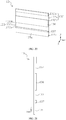
FIG. 1 is a schematic structural diagram of a device provided by the present application in a specific embodiment; -
FIG. 2 is a partial schematic structural diagram of a battery pack provided by the present application in a specific embodiment; -
FIG. 3 is a top view of a battery module inFIG. 2 in a first specific embodiment; -
FIG. 4 is a cross-sectional view of an A-A direction inFIG. 3 ; -
FIG. 5 is a schematic structural diagram of a cable tie inFIG. 4 , where a first cable tie is in a relaxed state; -
FIG. 6 is a partial enlarged view of part I inFIG. 4 in an embodiment; -
FIG. 7 is a partial enlarged view of part I inFIG. 4 in another embodiment; -
FIG. 8 is a top view ofFIG. 5 ; -
FIG. 9 is a partial enlarged view of part II inFIG. 8 ; -
FIG. 10 is a schematic structural diagram of the cable tie inFIG. 4 , where the first cable tie is in a tension state; -
FIG. 11 is an exploded view ofFIG. 5 ; -
FIG. 12 is a schematic structural diagram of a battery module inFIG. 2 in a second specific embodiment; -
FIG. 13 is an exploded view ofFIG. 12 ; -
FIG. 14 is a top view ofFIG. 12 ; -
FIG. 15 is a cross-sectional view of a B-B direction inFIG. 14 ; -
FIG. 16 is a partial enlarged view of part III inFIG. 15 ; -
FIG. 17 is a dimensional relationship diagram of each component inFIG. 16 ; -
FIG. 18 is a partial enlarged view of part IV inFIG. 16 ; -
FIG. 19 is a partial enlarged view of part V inFIG. 16 ; -
FIG. 20 is a schematic structural diagram of an end plate inFIG. 13 ; -
FIG. 21 is a side view ofFIG. 20 ; -
FIG. 22 is a top view ofFIG. 2 , where a battery module is a third specific embodiment; -
FIG. 23 is a cross-sectional view of a C-C direction inFIG. 22 ; -
FIG. 24 is a partial enlarged view of part VI inFIG. 23 ; -
FIG. 25 is a partial enlarged view of part VII inFIG. 24 ; -
FIG. 26 is a schematic structural diagram of an end plate inFIG. 23 ; -
FIG. 27 is a side view ofFIG. 26 . -
- D-device; M-battery pack;
- 1-battery module; 11-battery cell arrangement structure; 111- battery cell; 12-cable tie; 121-first cable tie; 121a-first tie body; 121b-first connection area; 121c-bending structure; 122-second cable tie; 122a-second tie body; 122b-second connection area; 123-third cable tie; 13-end plate; 131-first mounting groove; 131a-first bottom wall; 131b-first upper side wall; 131c-first lower side wall; 132-second mounting groove; 132a-second bottom wall; 132b-second upper side wall; 132c-second lower side wall; 133-third mounting groove; 133a-third bottom wall; 133b-third upper side wall; 133c-third lower side wall; 134-fourth mounting groove; 134a-fourth bottom wall; 134b-fourth upper side wall; 134c-fourth lower side wall; 135-fitting portion; 135a-fifth bottom wall; 136-body portion; 137-step portion; 138-locking portion; 138amounting hole; 139-lower end surface;
- 2-box body; 21- cavity; 22-mounting beam.
- The accompanying drawings, which are incorporated in and constitute a part of this specification, illustrate embodiments of the present application and, together with the description, serve to explain the principles of the present application.
- To understand technical solutions of the present application better, a detailed description of embodiments of the present application will be given below in combination with the accompanying drawings.
- It should be noted that embodiments described herein are merely a part, but not all, of the embodiments of the present application. All the other embodiments obtained by those of ordinary skill in the art based on the embodiments of the present application without any inventive effort shall fall within the scope of protection of the present application.
- The terms used in the embodiments of this application are only intended to describe specific embodiments, but are not intended to limit this application. The terms of "a", "the", and "the foregoing" in singular forms used in the embodiments of this application and the appended claims are intended to include a plural form, unless other meanings are clearly indicated in a context.
- It should be understood that the term "and/or" used in this specification describes only an association relationship for describing associated objects and represents that three relationships may exist. For example, A and/or B may represent the following three cases: Only A exists, both A and B exist, and only B exists. In addition, the character "/" in this specification generally indicates an "or" relationship between the associated objects.
- It should be noted that the terms representing directions such as "up", "down", "left" and "right" described in the embodiments of the present application are described from the angles shown in the accompanying drawings, and should not be understood as limitation on the embodiments of the present application. In addition, in the context, it should also be understood that when it is mentioned that an element is connected "up" or "down" the other element, it can not only be directly connected "up" or "down" the other element, but also be indirectly connected "up" or "down" the other element through an intermediate element.
- The embodiments of the present application provides a device D, a battery pack M and a
battery module 1 using abattery cell 111 as a power, where the device D using thebattery cell 11 as the power includes such mobile equipment as vehicles, ships and small airplanes. The device D includes a power source for providing a driving force to the device D, and the power source may be configured as thebattery module 1 that provides electrical energy to the device D. Specifically, the driving force of the device D may be all the electrical energy, and may also include the electrical energy and other energy sources (such as mechanical energy). The power source may be the battery module 1 (or the battery pack M), and may also be the battery module 1 (or the battery pack M) and an engine, etc. Therefore, any device D that can use thebattery cell 111 as the power is within a protection scope of the present application. -
FIG. 1 is a schematic structural diagram of a device provided by the present application in a specific embodiment. - As shown in
FIG. 1 , taking a vehicle as an example, the device D according to the embodiments of the present application may be a new energy vehicle, where the vehicle may include the battery pack M and a vehicle body, and the battery pack M is arranged in the vehicle body. -
FIG. 2 is a partial schematic structural diagram of a battery pack provided by the present application in a specific embodiment. - As shown in
FIG. 2 , the battery pack M includes abox body 2 and thebattery module 1 of the present application, where thebox body 2 has acavity 21, and thebattery module 1 is accommodated in thecavity 21. The number of thebattery module 1 may be one or more, andmultiple battery modules 1 are arranged in thecavity 21. -
FIG. 3 is a top view of a battery module inFIG. 2 in a first specific embodiment, andFIG. 4 is a cross-sectional view of an A-A direction inFIG. 3 ; - More specifically, as shown in
FIGS. 2 and3 , thebattery module 1 includes a plurality ofbattery cells 111 and a frame structure for fixing thebattery cells 111, where the plurality ofbattery cells 111 are stacked upon one another in a length direction X, and form a batterycell arrangement structure 11. The frame structure may include anend plate 13, and theend plate 13 is located at an end of the batterycell arrangement structure 11 in the length direction X. In a specific embodiment, the frame structure may further include a side plate (not shown), two side plates are located on two sides of the batterycell arrangement structure 11 in a width direction Y, and the side plate is connected with theend plate 13, so as to form the frame structure. In another embodiment, as shown inFIG. 4 , the frame structure may not be provided with the side plate, thebattery cells 111 are connected with each other through acable tie 12 after being stacked. At this time, theend plate 13 and thecable tie 12 form the above frame structure. - When the frame structure of the
battery module 1 includes theend plate 13 and thecable tie 12, generally, thecable tie 12 may be specifically made of metal or plastic material. When thecable tie 12 is made of the metal material, it has high tensile strength, and has a higher connection reliability to the batterycell arrangement structure 111. However, themetal cable tie 12 is hard to be elastically deformed, when the batterycell arrangement structure 11 is grouped into thebattery module 1, thecable tie 12 has a small deformation amount, which is not easy to achieve a pre-tension of the batterycell arrangement structure 11. When thecable tie 12 is made of the plastic material, it is easy to be elastically deformed. When thecable tie 12 surrounds periphery of thecell arrangement structure 11, tension may be first applied to thecable tie 12 so that thecable tie 12 is in a stretched state. After the surrounding is completed, the batterycell arrangement structure 11 may be tightened under an action of a resilient force of thecable tie 12, so as to achieve the pre-tension. However, theplastic cable tie 12 has the lower tensile strength, and when thebattery cell 111 in thebattery module 1 expands, there is a risk that thecable tie 12 may be broken under an expansion force, thereby reducing the connection reliability and affecting a normal operation of thebattery module 1. - On the basis of this, neither the
metal cable tie 12 nor theplastic cable tie 12 can achieve the higher tensile strength while being able to release the expansion force of thebattery cell 111. The embodiments of the present application improve the tensile strength of thecable tie 12 by changing the structure therefore, and release the expansion force of thebattery cell 111. -
FIG. 5 is a schematic structural diagram of a cable tie inFIG. 4 , where a first cable tie is in a relaxed state; - Specifically, as shown in
FIG. 5 , thecable tie 12 may be specifically a tie-like structure and surround outside the batterycell arrangement structure 11, and thecable tie 12 at least includes afirst cable tie 121 and asecond cable tie 122 of different materials, where at least part of thefirst cable tie 121 is located on a side of thesecond cable tie 122 close to thebattery cell 111, that is, at least part of thefirst cable tie 121 is located inside thesecond cable tie 122, where the inside refers to a side close to the batterycell arrangement structure 11, and the outside refers to a side far away from the batterycell arrangement structure 11. - Therefore, as shown in
FIG. 5 , in this embodiment, when at least part of thefirst cable tie 121 is located inside thesecond cable tie 122, thefirst cable tie 121 is closer to the batterycell arrangement structure 11 than thesecond cable tie 122. In addition, thefirst cable tie 121 and thesecond cable tie 122 may be made of different materials, so that thecable tie 12 can have different characteristics, which improves an applicability of thecable tie 12, performance of thecable tie 12, and the connection reliability of thecable tie 12 to thebattery cell 111. - Specifically, the tensile strength of the
first cable tie 121 can be greater than that of thesecond cable tie 122, where the tensile strength (or a strength limit) indicates the maximum stress value of the material before it is broken. Therefore, the greater the tensile strength, the greater bearing capacity of the material, that is, the material is not easy to be destroyed under an action of a same external force. In this embodiment, compared with thesecond cable tie 122, thecable tie 121 located inside has the higher strength. - In this case, an elastic modulus of the
first cable tie 121 is greater than that of thesecond cable tie 122, where according to Hooke's law, stress and strain of the material become proportional in an elastic deformation stage. Specifically, a proportional coefficient of the proportional relationship is the elastic modulus, and the elastic modulus is used to measure an ability of the material to resist elastic deformation. Therefore, the greater the elastic modulus, the great the stress required to make the material elastically deform, and the greater stiffness of the material (the harder to be elastically deformed), that is, when the stress is the same, the greater the elastic modulus, the smaller the elastic deformation. Therefore, in this embodiment, compared with thesecond cable tie 122, thefirst cable tie 121 located inside is much harder to be elastically deformed. - In summary, in the
cable tie 12, thefirst cable tie 121 located inside has the higher strength and is hard to be elastically deformed, while thesecond cable tie 122 located outside has the lower strength and is easy to be elastically deformed. Therefore, when thecable tie 12 including thefirst cable tie 121 and thesecond cable tie 122 is applied to thebattery module 1 in the embodiments of the present application, since thesecond cable tie 122 is easy to be elastically deformed, the pre-tension of thebattery module 1 can be implemented during grouping of thebattery cell 111. In this case, when thebattery cell 111 expands during an operation of thebattery module 1, since thefirst cable tie 121 has the higher strength, a risk of thecable tie 12 being damaged under an action of the expansion force can be reduced, so that thecable tie 12 still has the higher connection reliability to the expandedbattery module 1, thereby improving the performance of thecable tie 12 and increasing a service life of thebattery module 1. - More specifically, the
first cable tie 121 may be made of the metal material, and thesecond cable tie 122 may be made of the plastic material. It can be understood that the tensile strength of the metalfirst cable tie 121 is greater than that of the plasticsecond cable tie 122. In this case, the elastic modulus of the metalfirst strap 121 is greater than that of the plasticsecond cable tie 122. - In this embodiment, when the
battery cell 111 is grouped, thesecond cable tie 122 with a good elastic deformation ability is used to achieve the pre-tension of the batterycell arrangement structure 11, which improves the connection reliability of thecable tie 12 to the batterycell arrangement structure 11 when thebattery cell 111 is grouped, and improves grouping efficiency. In this case, when thebattery cell 111 expands, thefirst cable tie 121 with the higher strength prevents thecable tie 12 being damaged, which improves the connection reliability of thecable tie 12 to the batterycell arrangement structure 11 when thebattery cell 111 expands. - For example, the material of the
first cable tie 121 may be specifically metals such as stainless steel, aluminum, carbon steel, and the material of thesecond cable tie 122 may be specifically non-metals such as PET (polyester) plastic. - In a possible design, as shown in
FIG. 5 , at least part of thefirst cable tie 121 is abutted with thesecond cable tie 122 in a height direction Z of thebattery module 1, that is, in the height direction Z, thefirst cable tie 121 and thesecond cable tie 122 have overlapping parts, and the two are abutted with each other at an overlapping position. When there is a relative movement between thefirst cable tie 121 and thesecond cable tie 122, a position where the two are abutted with each other has frictional resistance, thereby reducing a tendency of the relative movement between the two. - When the
battery cell 111 in thebattery module 1 is not expanded, a force between thecable tie 12 and the batterycell arrangement structure 11 is relatively small, and in the height direction Z, a gravity of the metalfirst cable tie 121 is relatively large, that is, thefirst cable tie 121 has a tendency to move downward relative to thesecond cable tie 122. In this embodiment, the two are abutted with each other to generate friction, which can reduce a risk of thefirst cable tie 121 and/or thesecond cable tie 122 falling off, and improve the connection reliability of thecable tie 12 to the batterycell arrangement structure 11 when thebattery cell 111 is not expanded. -
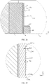
FIG. 6 is a partial enlarged view of part I inFIG. 4 in an embodiment, andFIG. 7 is a partial enlarged view of part I inFIG. 4 in another embodiment; - Specifically, as shown in
FIGS. 6 and7 , thefirst cable tie 121 has a first width W1, thesecond cable tie 122 has a second width W2. Among them, taking thefirst cable tie 121 as an example, thefirst cable tie 121 has three dimensions: length, width and thickness. And in thefirst cable tie 121 of the tie-like structure, the dimension with a largest value indicates the length of the first cable tie 121 (that is, a perimeter of the first cable tie 121), the dimension with a smallest value indicates the thickness of thefirst cable tie 121, and the dimension with a value between the maximum and minimum indicates the width of thefirst cable tie 121. Based on a perspective shown inFIGS. 6 and7 , the first width W1 of thefirst cable tie 121 refers to the dimension in the direction Z of thebattery module 1. - In a specific embodiment, W1≤W2, that is, the width of the
first cable tie 121 is less than or equal to that of thesecond cable tie 122. In the height direction Z, an abutting height of thesecond cable tie 122 and thefirst cable tie 121 is W3, where
first cable tie 121 and thesecond cable tie 122 is greater than or equal to half of the width of the smaller one. - In an embodiment shown in
FIG. 6 , in the height direction Z, the first width W1 of thefirst cable tie 121 and the second width W2 of thesecond cable tie 122 are equal, and the two completely overlap in the height direction Z, that is, the two are not staggered from each other, so that the abutting height of the two is W3=W1=W2. At this time, an abutting area between the two is the largest. When thefirst cable tie 121 moves relative to thesecond cable tie 122, the fraction between the two is relatively large, so that a risk of thefirst cable tie 121 and/or thesecond cable tie 122 falling off can be reduced. - In an embodiment shown in
FIG. 7 , in the height direction Z, thefirst cable tie 121 and thesecond cable tie 122 are partially overlapped, that is, there is a staggered part between the two in the height direction Z. At this time, the abutting height of the two is W3 <W1 and W3<W2. When W1≤W2,
first cable tie 121 and thesecond cable tie 122 can have a relatively large abutting area in the height direction Z, so that a risk of thefirst cable tie 121 and/or thesecond cable tie 122 falling off can be reduced. - In a possible design, as shown in
FIGS. 4-7 , twoend plates 13 of thebattery module 1 are located at two ends of the batterycell arrangement structure 11 in the length direction X, and thecable tie 12 is used to tightly fasten the twoend plates 13 and the batterycell arrangement structure 11. Specifically, as shown inFIGS. 6 and7 , theend plate 13 is provided with a first mountinggroove 131. In the height direction Z, a part of the first cable tie 121 (refers to a part of thefirst cable tie 121 in the width direction) and a part of the second cable tie 122 (refers to a part of thesecond cable tie 122 in the width direction) are located in the first mountinggroove 131, and thefirst cable tie 121 and thesecond cable tie 122 are at least partially abutted with each other in the first mountinggroove 131. - In this embodiment, as shown in
FIG. 6 , in the length direction X, the first mountinggroove 131 has a first bottom wall 131a. When a part of thefirst cable tie 121 and a part of thesecond cable tie 122 are located in the first mountinggroove 131, thefirst cable tie 121 located inside is abutted with the first bottom wall 131a. In this case, in the height direction Z, the first mountinggroove 131 has a firstupper side wall 131b and a firstlower side wall 131c arranged opposite to each other. And in the height direction Z, a part of thefirst cable tie 121 and a part of thesecond cable tie 122 are both located between the firstupper side wall 131b and the firstlower side wall 131c. - In a specific embodiment, in the height direction Z, the
second cable tie 122 may be abutted with both the firstupper side wall 131b and the secondlower side wall 131c. In this case, when the first width W1 of thefirst cable tie 121 is smaller than the second width W2 of thesecond cable tie 122, at least one end of thefirst cable tie 121 in the height direction is not abutted with a side wall of the first mountinggroove 131. When the first width W1 of thefirst cable tie 121 is equal to the second width W2 of thesecond cable tie 122, in the height direction Z, thefirst cable tie 121 may be abutted with both the firstupper side wall 131b and the secondlower side wall 131c. Or thefirst cable tie 121 and thesecond cable tie 122 may not be abutted with the side wall of the first mountinggroove 131. - In this embodiment, by arranging the first mounting
groove 131 on theend plate 13, the firstupper side wall 131b and the secondlower side wall 131c of the first mountinggroove 131 can restrict the movement of thecable tie 12 in the height direction Z, so as to improve the connection reliability of thecable tie 12 and theend plate 13. - Specifically, as shown in
FIG. 6 , in the length direction X of the battery module 1 (that is, in a thickness direction of the end plate 13), the depth of the first mountinggroove 131 is T3, the thickness of thefirst cable tie 121 is T1, and the thickness of thesecond cable tie 122 is T2, where T1+T2≤T3≤T1+T2+1 millimeter (mm). - In this embodiment, the depth T3 of the first mounting
groove 131 is greater than a sum of thicknesses of thefirst cable tie 121 and thesecond cable tie 122, so that thecable tie 12 does not increase the dimension of thebattery module 1 in the length direction X after it is arranged, which is conducive to a spatial arrangement of thebattery module 1. In this case, the depth of the first mountinggroove 131 should not be too large (not greater than T1+T2+1mm), so as to avoid that the strength of theend plate 13 at a position where the first mountinggroove 131 is provided is too low due to the excessive depth of the first mountinggroove 131, which increases a service life of theend plate 13. -
FIG. 8 is a top view ofFIG. 5 , andFIG. 9 is a partial enlarged view of part II inFIG. 8 . - On the other hand, as shown in
FIGS. 8 and9 , thefirst cable tie 121 located inside may further include a bendingstructure 121c. Therefore, when the first cable tie is stressed, the bendingstructure 121c can be deformed. - In this embodiment, the
first cable tie 121 is located inside (closer to thebattery cell 111 compared with the second cable tie 122), and the tensile strength and elastic modulus thereof are both relatively large (such as the metal cable tie). When thebattery cell 111 of thebattery module 1 expands, the bendingstructure 121c of thefirst cable tie 121 can be deformed under the action of the expansion force, so that thefirst cable tie 121 can release the expansion force of thebattery cell 111, which improves safety and increases the service life of thebattery module 1. And thefirst cable tie 121 can also adapt to the deformed batterycell arrangement structure 11, so that thecable tie 12 can be applied tobattery modules 1 of different dimensions. -
FIG. 10 is a schematic structural diagram of the cable tie inFIG. 4 , where the first cable tie is in a stretched state, andFIG. 11 is an exploded view ofFIG. 5 . - In a specific embodiment, as shown in
FIGS. 5 ,8 and11 , thefirst cable tie 121 may be an annular wave structure, that is, thefirst cable tie 121 may include a plurality of the bendingstructures 121c, and at least two bendingstructures 121c have opposite bending directions. In this case, each bendingstructure 121c is an arc structure, andadjacent bending structures 121c are in a circular arc transition to form thefirst cable tie 121 of the wave structure. Moreover, in this embodiment, the wave structure of thefirst cable tie 121 may be formed by stamping during processing. - In this embodiment, the
first cable tie 121 is the wave structure, which means that thefirst cable tie 121 is wavy when thebattery cell 111 is not significantly expanded (thefirst cable tie 121 is not significantly deformed), or thefirst cable tie 121 is formed into the wave structure by processing (when it does not surround the battery cell arrangement structure 11). When thefirst cable tie 121 surrounds the batterycell arrangement structure 11, thebattery cell 111 expands, and when the expansion force makes the deformation amount of the batterycell arrangement structure 11 small, the deformed batterycell arrangement structure 11 first acts on thesecond cable tie 122 located outside after the batterycell arrangement structure 11 is deformed, so that thesecond cable tie 122 is elastically stretched, so as to release the small expansion force and improve the connection reliability of thecable tie 12 to the expanded batterycell arrangement structure 11. At this time, thefirst cable tie 121 is in the relaxed state. - When the expansion force of the
battery cell 111 makes the deformation amount of the batterycell arrangement structure 11 large, in addition to thesecond cable tie 122 with the higher elastic deformation ability can be elastically deformed, thefirst cable tie 121 of the wave structure can also be deformed, so that at least part of the wave structure is straightened and thefirst cable tie 121 is in a tightened state. Specifically, in this state, the deformation of thefirst cable tie 121 refers to a change in shape of the first cable tie 121 (the wave shape is straightened into a rectangle), not the deformation of the material of thefirst cable tie 121. Of course, when the expansion force is larger, the material of thefirst cable tie 121 can also be deformed to a certain extent. At this time, thefirst cable tie 121 is completely straightened into the rectangle, a state shown inFIG. 10 . In this case, since thefirst cable tie 121 has the relatively high tensile strength, when the larger expansion force is released, a risk of thecable tie 12 being broken under the action of the expansion force can be reduced. And during the deformation of thefirst cable tie 121, the dimension of the batterycell arrangement structure 11 increases, and thesecond cable tie 122 can be elastically deformed so as to adapt to the batterycell arrangement structure 11, and to apply the pre-tension to the batterycell arrangement structure 11. - In another specific embodiment, the length of the
first cable tie 121 is greater than a perimeter of the batterycell arrangement structure 11, and the length of thefirst cable tie 121 is greater than that of thesecond cable tie 122. As described above, the length of thefirst cable tie 121 of an annular structure refers to the perimeter of thefirst cable tie 121. And when thesecond cable tie 122 surrounds outside thefirst cable tie 121, thesecond cable tie 122 with the relatively small length can apply a squeezing force to thefirst cable tie 121 with the relatively large length, so that thefirst cable tie 121 forms one ormore bending structures 121c, and each bendingstructure 121c can be deformed when thefirst cable tie 121 is stressed. - In this embodiment, the
first cable tie 121 and thesecond cable tie 122 can both be formed into rectangular structures that can surround outside the batterycell arrangement structure 11 during processing, and the perimeter of thefirst cable tie 121 is greater than that of thesecond cable tie 122. When the two surround the outside the batterycell arrangement structure 11, thesecond cable tie 122 with the relatively small perimeter located outside can apply the squeezing force to thefirst cable tie 121 with the relatively large perimeter located inside, so as to form the bendingstructure 121c in thefirst cable tie 121. - In this embodiment, the
first cable tie 121 and thesecond cable tie 122 surround outside the batterycell arrangement structure 11, and when the expansion force of thebattery 111 makes the deformation amount of the batterycell arrangement structure 11 large, the bendingstructure 121c in thefirst cable tie 121 formed by squeezing can also be deformed, where the deformation of the bendingstructure 121c also refers to the change in the shape, that is, under the action of the expansion force, the bendingstructure 121c is gradually stretched into a linear structure until thefirst cable tie 121 including a plurality of the bendingstructures 121c is straightened into a rectangular structure. Of course, when the expansion force continues to increase, the material of thefirst cable tie 121 may also be deformed to a certain extent. - Therefore, a specific formation mode of the bending
structure 121c is not limited, as long as thefirst cable tie 121 includes the bendingstructure 121c that can be deformed. - In a possible design, as shown in
FIG. 11 , thefirst cable tie 121 and thesecond cable tie 122 are annular structures that can surround the batterycell arrangement structure 11, and the two are specifically formed into the annular structure through the tie-like structure. Specifically, thefirst cable tie 121 is formed by afirst tie body 121a, and two end positions of thefirst tie body 121a are connected to form thefirst cable tie 121, and a first connection area 121b is formed at a junction, where two connection positions of thefirst cable tie 121a need to be able to surround the batterycell arrangement structure 11 after being connected to form thefirst cable tie 121. Likewise, thesecond cable tie 122 is formed by asecond tie body 122a, and two end positions of thesecond tie body 122a are connected to form thesecond cable tie 122, and a second connection area 122b is formed at a junction, where two connection positions of thesecond tie body 122a need to be able to surround the batterycell arrangement structure 11 after being connected to form thesecond cable tie 122. - In this embodiment, after being stressed, the
first cable tie 121 is easily broken in the first connection area 121b, and thesecond cable tie 122 is easily broken in the second connection area 122b, that is, two connection areas are weak areas of two cable ties. - As shown in
FIG. 11 , the first connection area 121b of thefirst cable tie 121 and the second connection area 122b are staggered from each other, that is, the weak areas of the two cable ties are staggered from each other, so as to reduce a risk of disconnecting of both connection areas under the action of the expansion force, which increases the service life and improves the connection reliability of thecable tie 12. - Specifically, one of the first connection area 121b and the second connection area 122b is located at an end of the battery
cell arrangement structure 11 in the length direction X, and the other is located at an end of the batterycell arrangement structure 11 in the width direction Y, so that the two connection areas are staggered from each other. Specifically, as shown inFIG. 11 , the first connection area 121b of thefirst cable tie 121 is located at an end of the batterycell arrangement structure 11 in the width direction Y, and the second connection area 122b of thesecond cable tie 122 is located at an end of the batterycell arrangement structure 11 in the length direction X. - Additionally, the embodiments of the present application further provide an assembly method of the
battery module 1, where thebattery module 1 includes the batterycell arrangement structure 11 and thecable tie 12, thecable tie 12 surrounds outside the batterycell arrangement structure 11, and thecable tie 12 at least includes thefirst cable tie 121 and thesecond cable tie 122 of the different materials, where the assembly method of thebattery module 1 includes the following steps: - S2: sleeving the
first cable tie 121 outside the batterycell arrangement structure 11.
Specifically, the perimeter of thefirst cable tie 121 may be greater than that of the batterycell arrangement structure 11, so that thefirst cable tie 121 is in the relaxed state when it is sleeved outside the batterycell arrangement structure 11. - S3: surrounding the battery
cell arrangement structure 11 with thesecond tie body 122a of thesecond cable tie 122, and thesecond tie body 122a surrounds thefirst cable tie 121, so that thesecond tie body 122a covers at least part of thefirst cable tie 121 in the height direction Z. - S4: connecting the
second tie body 122a to form an annularsecond cable tie 122. - Specifically, the perimeter of the
second cable tie 122 surrounded by thesecond cable tie 122a is smaller than that of thefirst cable tie 121, and the perimeter of thesecond cable tie 122 may be equal to or slightly smaller than that of the batterycell arrangement structure 11. At this time, thesecond cable tie 122 can implement the pre-tension to the batterycell arrangement structure 11 after surrounding the batterycell arrangement structure 11. Additionally, since the perimeter of thefirst cable tie 121 is greater than that of thesecond cable tie 122, thefirst cable tie 121 forms at least onebending structure 121c after thefirst cable tie 121 and thesecond cable tie 122 surround the batterycell arrangement structure 11. And the bendingstructure 121c can be deformed when thefirst cable tie 121 is stressed. - Additionally, in this embodiment, the
first cable tie 121 may be specifically made of the material with the relatively large tensile strength and elastic modulus, and thesecond cable tie 122 may be specifically made of the material with the relatively small tensile strength and elastic modulus. For example, thefirst cable tie 121 may be specifically made of the metal material, and thesecond cable tie 122 may be specifically made of the plastic material. During assembly, thesecond cable tie 122 is located outside thefirst cable tie 121 through steps S3 and S4, and the pre-tension to the batterycell arrangement structure 11 can be implemented through thefirst cable tie 121 and thesecond cable tie 122. In this case, when thebattery cell 111 expands, it can release the expansion force, and has the higher connection reliability to the expanded batterycell arrangement structure 11 - In this embodiment, the
first tie body 121a is welded to form thefirst cable tie 121, and then thefirst cable tie 121 is sleeved outside the batterycell arrangement structure 11, there is no need to weld thefirst tie body 121a after it is connected with the batterycell arrangement structure 11, so as to avoid damaging thebattery cell 111 when welding thefirst tie body 121a, which improves the safety and increases the service life of thebattery module 1. - Specifically, the
first cable tie 121 includes thefirst tie body 121a, that is, thefirst cable tie 121 is formed by thefirst tie body 121a. Before step S2, the assembly method may further include:
S1: welding thefirst tie body 121a to form the annularfirst cable tie 121. - In this embodiment, the first cable tie is made of the metal material. Therefore, when the
first tie body 121a is used to form thefirst cable tie 121, welding can be used, and during forming, two positions of thefirst tie body 121a are welded to form the annular structure. Moreover, two welding positions can be selected according to the specific length of thefirst tie body 121a, as long as thefirst cable tie 121 can surround the batterycell arrangement structure 11 and the perimeter of thefirst cable tie 121 is greater than that of thesecond cable tie 122. - Or the
cable tie 121a with the length of the perimeter of thefirst cable tie 121 may be selected first, and then thefirst tie body 121a is welded and connected end to end to form the annularfirst cable tie 121. Specifically, laser welding, resistance welding and other ways may be adopted. Or when the length of thefirst tie body 121a is greater than the perimeter of thefirst cable tie 121, after the two positions of thefirst tie body 121a are welded to form the annular structure, the annular structure is also connected with excess tie heads (not involved in forming the annular structure). At this time, part of the tie heads may be removed from the annular structure (for example, by means of cutting), so as to form thefirst cable tie 121. - More specifically, the
second tie body 122a may be specifically made of the plastic material. Based on this, the step S4 may be specifically:
S41: connecting thesecond tie body 122a by hot-melting to form the annularsecond cable tie 122. - In this embodiment, during the process of thermally connecting the
second tie body 122a to form thesecond cable tie 122, thesecond cable tie 122 can be stretched to apply pressure on the batterycell arrangement structure 11, so as to implement the pre-tension to the batterycell arrangement structure 11. - In the above embodiments, as shown in
FIG. 2 , in the height direction Z, one end of the batterycell arrangement structure 11 is fixedly connected with thebox body 2, and thefirst cable tie 121 and thesecond cable tie 122 surround the other end of the batterycell arrangement structure 11. - Specifically, as shown in
FIG. 2 , bottom of the batterycell arrangement structure 11 is fixedly connected with that of thebox body 2, and the two may specifically be bonded by structural glue or be connected by other means. Therefore, thefirst cable tie 121 and thesecond cable tie 122 surround an upper end of the batterycell arrangement structure 11, that is, an end far away from thebox body 2, and a specific position of thefirst cable tie 121 and thesecond cable tie 122 fitted with the batterycell arrangement structure 11 can be set according to actual conditions, as long as it can implement the grouping and fixation of thebattery module 1 through a fixed connection with thebox body 2, and thefirst cable tie 121 and thesecond cable tie 122. - Additionally, the
battery module 1 may only include an upper cable tie, and the upper cable tie includes thefirst cable tie 121 and thesecond cable tie 122 in the above embodiments. Or thebattery module 1 may also include the upper cable tie and a lower cable tie, the upper cable tie includes thefirst cable tie 121 and thesecond cable tie 122 in the above embodiments, and the lower cable tie may be arranged at an end close to the bottom of thebox body 2. The connection reliability between thecable tie 12 and the batterycell arrangement structure 11 can be improved through the upper cable tie and the lower cable tie. -
FIG. 12 is a schematic structural diagram of a battery module inFIG. 2 in a second specific embodiment,FIG. 13 is an exploded view ofFIG. 12 ,FIG. 14 is a top view ofFIG. 12 , andFIG. 15 is a cross-sectional view of a B-B direction inFIG. 14 . - In another possible design, in the embodiments shown in
FIGS. 12, 13 ,14 and 15 , the battery pack M includes thefirst cable tie 121 and thesecond cable tie 122, where thefirst cable tie 121 and thesecond cable tie 122 surround outside the batterycell arrangement structure 11. Specifically, the tensile strength of thefirst cable tie 121 is greater than that of thesecond cable tie 122, and the elastic modulus of thefirst cable tie 121 is greater than that of thesecond cable tie 122, that is, the strength of thefirst cable tie 121 is greater than that of thesecond cable tie 122, while the deformation ability of thesecond cable tie 122 is greater than that of thefirst cable tie 121, On the basis of this, thefirst cable tie 121 and thesecond cable tie 122 are arranged in the height direction Z of thebattery module 1, and thesecond cable tie 122 is close to an end fixedly connecting thebattery module 1 and thebox body 2, that is, thefirst cable tie 121 is far away from the end fixedly connecting thebattery module 1 and thebox body 2, where thebattery module 1 and thebox body 2 may be bonded by the structural glue, or thebattery module 1 may be locked in thebox body 2 by bolts. - In this embodiment, in the height direction Z, one end of the
battery module 1 is fixedly connected with thebox body 2. Therefore, a grouping reliability of eachbattery cell 111 is higher at this position, and a reliable grouping can be implemented by only setting thesecond cable tie 122 with the lower tensile strength. While with respect to an end not connecting thebattery module 1 and thebox body 2, thebattery cell 111 needs to be grouped by a higher strength structure, that is, in this embodiment, thefirst cable tie 121 with the higher tensile strength is arranged at a position far away from the end fixedly connecting thebattery module 1 and thebox body 2, so that a grouping of thebattery cells 111 at the position may be implemented by thefirst cable tie 121 with the higher strength, and efficiency of the grouping thereof is also improved. - In this case, when the
battery cell 111 of thebattery module 1 expands, a position of thecell arrangement structure 11 away from an end connected with thebox body 2 expands and deforms greatly. Therefore, when thefirst cable tie 121 with the higher tensile strength is arranged at this position, a risk of thefirst tie 121 being broken under the action of the expansion force can be reduced. - Specifically, the
first cable tie 121 may be specifically made of the metal material, and thesecond cable tie 122 may be specifically made of the plastic material. With respect to thefirst cable tie 121 and thesecond cable tie 122 with same volume, weight of thesecond cable tie 122 is smaller than that of thefirst cable tie 121. - Therefore, in this embodiment, cable ties with the different tensile strength are arranged according to different strength requirements of different positions, which can implement a grouping of the
battery module 1 and has the higher grouping reliability. In this case, when thesecond cable tie 122 with the lower tensile strength is arranged at a position with the lower strength requirement, the weight of thebattery module 1 can also be reduced, which improves an energy density thereof. - In summary, in this embodiment, the
first cable tie 121 and thesecond cable tie 122 may be arranged at intervals in the height direction Z. Or in the embodiments shown inFIGS. 4 and5 , thefirst cable tie 121 and thesecond cable tie 122 of the different materials are approximately at a same height, and thefirst cable tie 121 is located inside thesecond cable tie 122. -
FIG. 16 is a partial enlarged view of part III inFIG. 15 , andFIG. 17 is a dimensional relationship diagram of each component inFIG. 16 . - Specifically, as shown in
FIGS. 16 and 17 , theend plate 13 is provided with asecond mounting groove 132 and athird mounting groove 133. In the height direction Z of thebattery module 1, the second mountinggroove 132 is located above the third mountinggroove 133, where a part of the first cable tie 121 (refers to a part of thefirst cable tie 121 in the width direction) is located in the second mountinggroove 132. In this case, a part of the second cable tie 122 (refers to a part of thesecond cable tie 122 in the width direction) is located in the third mountinggroove 133. -
FIG. 18 is a partial enlarged view of part I inFIG. 16 , andFIG. 19 is a partial enlarged view of part I inFIG. 16 . - Specifically, as shown in
FIGS. 18 and 19 , in the length direction X of thebattery module 1, the second mountinggroove 132 has asecond bottom wall 132a. When a part of thefirst cable tie 121 is located in the second mountinggroove 132, thefirst cable tie 121 is abutted with thesecond bottom wall 132a. In this case, in the height direction Z, the second mountinggroove 132 includes a secondupper side wall 132b and a secondlower side wall 132c arranged opposite to each other, and thefirst cable tie 121 is located between the secondupper side wall 132b and the secondlower side wall 132c. In this case, thefirst cable tie 121 may or may not be abutted with two side walls. Likewise, in the length direction X of thebattery module 1, the third mountinggroove 133 includes a third bottom wall 133a, when a part of thesecond cable tie 122 is located in the third mountinggroove 133, thesecond cable tie 122 is abutted with the third bottom wall 133a. In this case, in the height direction Z, the third mountinggroove 133 includes a thirdupper side wall 133b and a thirdlower side wall 133c arranged opposite to each other, and thesecond cable tie 122 is located between the thirdupper side wall 133b and the thirdlower side wall 133c. In this case, thesecond cable tie 122 may or may not be abutted with the two side walls. - In this embodiment, by arranging the second mounting
groove 132 and the third mountinggroove 133 on theend plate 13, the secondupper side wall 132b and the secondlower side wall 132c of the second mountinggroove 132 can restrict the movement of thefirst cable tie 121 in the height direction Z, and the thirdupper side wall 133b and the thirdlower side wall 133c of the third mountinggroove 133 can restrict the movement of thesecond cable tie 122 in the height direction Z, so as to improve the connection reliability between thefirst cable tie 121 and thesecond cable tie 122 and theend plate 13. - Specifically, as shown in
FIGS. 18 and 19 , in the length direction X, the depth of the second mountinggroove 132 is T4, and the depth of the third mountinggroove 133 is T5. The thickness of thefirst cable tie 121 is T1, and the thickness of thesecond cable tie 122 is T2, 0<T4-T1<0.5mm, 0<T5-T2<0.5mm. - In this embodiment, the depth T4 of the second mounting
groove 132 is greater than the thickness T1 of thefirst cable tie 121, and the depth T5 of the third mountinggroove 133 is greater than the thickness T2 of thesecond cable tie 122, so that thefirst cable tie 121 and thesecond cable tie 122 do not increase the dimension of thebattery module 1 in the length direction X after they are arranged, which is conducive to the spatial arrangement of thebattery module 1. In this case, the depth T4 of the second mountinggroove 132 and the depth T5 of the third mountinggroove 133 should not be too large (T4-T1<0.5mm, T5-T2<0.5mm), so as to avoid that the strength of theend plate 13 at a position where the second mountinggroove 132 and the third mountinggroove 133 are provided is too low due to the excessive depths of the second mountinggroove 132 and the third mountinggroove 133, which increases the service life of theend plate 13. - More specifically, as shown in
FIG. 17 , in the height direction Z, the second mountinggroove 132 has a first centerline O1, and in the height direction Z, there is a first distance H1 between the first centerline O1 and alower end surface 139 of theend plate 13. Likewise, in the height direction Z, the third mountinggroove 133 has a second centerline O2, and in the height direction Z, there is a second distance H2 between the second centerline O2 and thelower end surface 139. In this case, theend plate 13 has a first height L1 in the height direction Z, where

- In this embodiment, the first distance H1 can characterize a setting height of the second mounting
groove 132 relative to thelower end surface 139 of theend plate 13. Likewise, the second distance H2 can characterize a setting height of the third mountinggroove 133 relative to the end surface of theend plate 13. Thebattery module 1 is fixedly connected with thebox body 2 at an end close to thelower end surface 139 of theend plate 13. Therefore, a setting position of the second mountinggroove 132 is higher than that of the third mountinggroove 133, that is, H1 >H2. - In this case, after the
end plate 13 is provided with the second mountinggroove 132 and the third mountinggroove 133 arranged in the height direction Z, different thicknesses of theend plate 13 makes the strength and stiffness of theend plate 13 are different. When

end plate 13 are still relatively uniform. - Additionally, in the embodiments shown in
FIGS. 16 and 17 , theend plate 13 further includes a firstfitting portion 136 and a secondfitting portion 135, where the second mountinggroove 132 and the third mountinggroove 133 are arranged in the firstfitting portion 136. And in the height direction Z, the secondfitting portion 135 is located below the third mountinggroove 133. At this time, thebattery module 1 and thebox body 2 can be bonded, and can also be connected through a mountingbeam 22 and theend plate 13. In this case, the batterycell arrangement structure 11 of thebattery module 1 is grouped through thefirst cable tie 121 and thesecond cable tie 122. - On the other hand, when the thickness of the
end plate 13 of thebattery module 1 is relatively small, structural strength cannot be met. Therefore, theend plate 13 is generally a flat structure with a certain thickness, so as to meet a strength requirement of thebattery module 1. However, when the thickness of theend plate 13 is relatively large, the energy density of thebattery module 1 is affected. -
FIG. 20 is a schematic structural diagram of an end plate inFIG. 13 , andFIG. 21 is a side view ofFIG. 20 . - In order to solve this technical problem, as shown in
FIGS. 20 and 21 , theend plate 13 of thebattery module 1 may include the firstfitting portion 136 and the secondfitting portion 135, where in the height direction Z of thebattery module 1, the secondfitting portion 135 is located below the firstfitting portion 136, and the thickness of the secondfitting portion 135 is smaller than that of the firstfitting portion 136. In this case, thebattery module 1 is fixed in thebox body 2 of the battery pack M, and thebattery module 1 can be fitted and fixed with thebox body 2 through the secondfitting portion 135. - In this embodiment, the thicknesses of the first
fitting portion 136 and the secondfitting portion 135 of theend plate 13 are different, so that theend plate 13 is a structure with different thicknesses at different positions, so as to reduce the weight of theend plate 13 and improve the energy density of thebattery module 1 while ensuring the higher strength of theend plate 13. Additionally, when thickness of theend plate 13 at different positions is not exactly the same and thebattery module 1 is mounted in thebox body 2, a fit between theend plate 13 and other parts in thebox body 2 can also be easily implemented, which improves assembly efficiency. - Specifically, as shown in
FIG. 2 , the mountingbeam 22 is arranged in thecavity 21 of thebox body 2. In the length direction X of thebattery module 1, the mountingbeam 22 is located at an end of the batterycell arrangement structure 11. Therefore, the mountingbeam 22 can restrict a movement of the batterycell arrangement structure 11 in the length direction X, which improves a mounting reliability of thebattery module 1 in thebattery pack 2. In this case, when thebattery module 1 is mounted between two mountingbeams 22, theend plates 13 are close to the two mountingbeams 22, respectively, and are fitted with the mounting beams 22. - Specifically, as shown in
FIG. 22 , the mountingbeam 22 is fitted with the secondfitting portion 135 of thecorresponding end plate 13. And in the length direction X, the secondfitting portion 135 has afifth bottom wall 135a, where thefifth bottom wall 135a faces the corresponding mountingbeam 22, and there is a predetermined gap t between thefifth bottom wall 135a and the mountingbeam 22 in the length direction X, specifically, a range of t is t<0.5mm. - In this embodiment, the
end plate 13 can be fitted with the mountingbeam 22 through the secondfitting portion 135, and thebattery module 1 can be mounted between the two mountingbeams 22 and can fit space between the two mountingbeams 22 by changing the thickness of the secondfitting portion 135. Additionally, when there is the predetermined gap t between thefifth bottom wall 135a of the secondfitting portion 135 and the mountingbeam 22 in the length direction X, thebattery module 1 can be easily mounted between the two mountingbeams 22. In this case, when thebattery cell 111 of thebattery module 1 expands in the length direction X, the predetermined gap t can provide a distance that theend plate 13 moves in the length direction X during the expansion, so as to reduce a risk of the firstfitting portion 136 and the secondfitting portion 135 with different thicknesses being broken due to expansion difference, which increases the service life of theend plate 13. - Additionally, when the
battery cell 111 in thebattery module 1 expands, theend plate 13 moves toward the mountingbeam 22 in the length direction X, so that thebottom wall 135a of the secondfitting portion 135 is abutted with the mountingbeam 22, the secondfitting portion 135 is subjected to a reverse force of the mountingbeam 22, and the mountingbeam 22 can limit theend plate 13 in the length direction X. In this case, when thebattery cell 111 continues to expand, due to a limiting effect of the mountingbeam 22, the secondfitting portion 135 is no longer expands and deforms, while the firstfitting portion 136 located above the secondfitting portion 135 can continue to expand and deform. Therefore, in a direction from top to bottom, the deformation amount of theend plate 13 gradually decreases from top to bottom. Therefore, theend plate 13 has a structure with the large thickness above (the first fitting portion 136) and the small thickness below (the second fitting portion 135), so that the stiffness of theend plate 13 is large at the firstfitting portion 136, and small at the secondfitting portion 135. - Specifically, the predetermined gap t should not be too large or too small. When the predetermined gap t is too large, during the expansion of the
battery cell 111, theend plate 13 moves a relatively large distance in the length direction X under the action of the expansion force. When thebattery module 1 includes thecable tie 12, the deformation amount of thecable tie 12 is relatively large, resulting in that thecable tie 12 is broken before thefifth bottom wall 135a of the secondfitting portion 135 in theend plate 13 contacts the mountingbeam 22. And when the predetermined gap t is too small, thebattery module 1 has relatively small expansion space, which is not conducive to releasing the expansion force. Therefore, comprehensively considering the above factors, a size of the predetermined gap t can be reasonably selected. For example, the predetermined gap may be 0.2mm, 0.4mm and so on. - Specifically, as shown in
FIG. 17 , the thickness of the firstfitting portion 136 is t1, the thickness of the secondfitting portion 135 is t2,
- In this embodiment, when t1>t2, the stiffness of the first
fitting portion 136 is greater than that of the second fitting portion. when
fitting portion 136 and that of the secondfitting portion 135 is not too large, so as to reduce a risk of theend plate 13 being broken between the firstfitting portion 136 and the secondfitting portion 135 under the action of the expansion force due to an excessive deformation difference of between the two. - More specifically, as shown in
FIG. 17 , in the height direction Z, theend plate 13 has a first height L1, and the secondfitting portion 135 has a second height L2,
- In this embodiment, the second height L2 of the second
fitting portion 135 with the relatively small thickness should not be too large, that is, less than or equal to 1/3 of the overall height of theend plate 13, so as to prevent relatively low overall strength of theend plate 13 when the height of the secondfitting portion 135 is too high. - In a possible design, as shown in
FIGS. 24 and27 , astep portion 137 is formed between the firstfitting portion 136 and the secondfitting portion 135, and in the height direction Z, the mountingbeam 22 is abutted with thestep portion 137. - Therefore, in this embodiment, the height of the second
fitting portion 135 is equal to that of the mountingbeam 22, so that when thebattery module 1 is mounted in thebox body 2, thestep portion 137 of theend plate 13 can be abutted with an upper surface of the mountingbeam 22, so that the mountingbeam 22 supports theend plate 13 in the height direction Z, which can improve the connection reliability between the mountingbeam 22 and theend plate 13. - Furthermore, as shown in
FIGS. 26 and 27 , theend plate 13 may further include a lockingportion 138, where the lockingportion 138 protrudes from theend plate 13 and extends toward the mountingbeam 22. In this case, as shown inFIG. 27 , a lower end surface of the lockingportion 138 is flush with a step surface of thestep portion 137, when thebattery module 1 is mounted in thebox body 2, the upper surface of the mountingbeam 22 can be abutted with the step surface of thestep portion 137 and a lower surface of the lockingportion 138. In this case, the lockingportion 138 may also be provided with a mountinghole 138a, the mountinghole 138a is used to connect with the mountingbeam 22. Specifically, the mountinghole 138a may be a bolt hole, so that theend plate 13 and the mountingbeam 22 can be connected by the bolts. - In a specific embodiment, as shown in
FIGS. 24 and 25 , the battery pack M may further include athird cable tie 123, and in the height direction Z, thethird cable tie 123 surrounds an upper portion of the batterycell arrangement structure 11 away from the mountingbeam 22. - In this embodiment, when the
battery cell 111 of thebattery module 1 expands so that theend plate 13 moves close to the mountingbeam 22, the two mountingbeams 22 can limit theend plate 13 through the secondfitting portion 135, so as to improve the grouping reliability of thebattery module 1 at a position corresponding to the mountingbeam 22. In this case, in order to improve the reliability of thebattery module 1 at the upper portion away from the mountingbeam 22, thebattery module 1 may also be provided with thethird cable tie 123. The batterycell arrangement structure 11 can be limited in the height direction Z through thethird cable tie 123 and the mountingbeam 22, which improves the grouping reliability of thebattery cell 111. - Specifically, as shown in
FIGS. 25-27 , theend plate 13 is provided with a fourth mountinggroove 134. In the height direction Z, a part of the third cable tie 123 (refers to a part of thethird cable tie 123 in the height direction) is located in the fourth mountinggroove 134. In this embodiment, in the length direction X, the fourth mountinggroove 134 has a fourth bottom wall 134a. When the part of thethird cable tie 123 is located in the fourth mountinggroove 134, thethird cable tie 123 is abutted with the fourth bottom wall 134a in the length direction X. In this case, in the height direction Z, the fourth mountinggroove 134 has a fourthupper side wall 134b and a fourthlower side wall 134c arranged opposite to each other. And in the height direction Z, thethird cable tie 123 is located between the fourthupper side wall 134b and the fourthlower side wall 134c. - In a specific embodiment, in the height direction Z, the
third cable tie 123 may also be abutted with both the fourthupper side wall 134b and the fourthlower side wall 134c, or thethird cable tie 123 may not be abutted with at least one side wall of the fourth mountinggroove 134. In the embodiment shown inFIG. 25 , in the height direction Z, thethird cable tie 123 is not abutted with both the fourthupper side wall 134b and the fourthlower wall 134c. - In this embodiment, by arranging the fourth mounting
groove 134 on theend plate 13, the fourthupper side wall 134b and the fourthlower side wall 134c of the fourth mountinggroove 134 can restrict a movement of thethird cable tie 123 in the height direction Z, so that the connection reliability between thethird cable tie 123 and theend plate 13 can be improved. - Specifically, as shown in
FIG. 25 , thethird cable tie 123 has a sixth thickness T6, and the depth of the fourth mountinggroove 134 is T7, 0 <T7-T6<0.5mm. - In this embodiment, the depth T7 of the fourth mounting
groove 134 is greater than the sixth thicknesses T6 of thethird cable tie 123, so that thethird cable tie 123 does not increase the dimension of thebattery module 1 in the length direction X after it is arranged, which is conducive to the spatial arrangement of thebattery module 1. In this case, the depth of the first mountinggroove 131 should not be too large (T7-T6<0.5mm), so as to avoid that the strength of theend plate 13 at a position where the fourth mountinggroove 134 is provided is too low due to the excessive depth of the fourth mountinggroove 134, which increases the service life of theend plate 13. - The above descriptions are only preferred embodiments of the present application, and are not intended to limit the present application. For those skilled in the art, the present application can have various modifications and changes. Any modification, equivalent substitution, improvement or the like, made within the spirit and principle of the present application shall fall within the protection scope of the present application.
Claims (16)
- A battery module (1), comprising:a battery cell arrangement structure (11) comprising a plurality of battery cells (111) stacked upon one another;a cable tie (12), the cable tie (12) surrounding outside the battery cell arrangement structure (11), and at least comprising a first cable tie (121) and a second cable tie (122) of different materials; andwherein at least part of the first cable tie (121) is located on a side of the second cable tie (122) close to the battery cell (111).
- The battery module (1) according to claim 1, wherein tensile strength of the first cable tie (121) is greater than that of the second cable tie (122), and an elastic modulus of the first cable tie (121) is greater than that of the second cable tie (122).
- The battery module (1) according to claim 2, wherein the first cable tie (121) comprises a metal cable tie, and the second cable tie (122) comprises a plastic cable tie.
- The battery module (1) according to any one of claims 1 to 3, wherein in a height direction (Z) of the battery module (1), at least part of the first cable tie (121) is abutted with the second cable tie (122).
- The battery module (1) according to any one of claims 1 to 4, wherein the first cable tie (121) comprises a bending structure (121c), so that the bending structure (121c) is capable of deformation when the first cable tie (121) is stressed.
- The battery module (1) according to claim 5, wherein the first cable tie (121) is an annular wave structure.
- The battery module (1) according to claim 5 or 6, wherein a length of the first cable tie (121) is greater than a perimeter of the battery cell arrangement structure (11), and the length of the first cable tie (121) is greater than that of the second cable tie (122); and
the second cable tie (122) surrounds outside the first cable tie (121), so that the second cable tie (122) squeezes the first cable tie (121) to form the bending structure (121c). - The battery module (1) according to any one of claims 4 to 7, wherein the first cable tie (121) has a first width W1, and the second cable tie (122) has a second width W2, W1≤W2; and
in the height direction (Z), an abutting height of the second cable tie (122) and the first cable tie (121) is W3,
- The battery module (1) according to any one of claims 4 to 8, wherein the first cable tie (121) is connected by a first tie body (121a) to form an annular first cable tie (121), and a first connection area (121b) is formed at a junction;the second cable tie (122) is connected by a second tie body (122a) to form an annular second cable tie (122), and a second connection area (122b) is formed at a junction; andthe first connection area (121b) and the second connection area (122b) are staggered from each other.
- The battery module (1) according to any one of claims 1 to 9, wherein the battery module (1) further comprises an end plate (13), and the end plate (13) is located on an end of the battery cell arrangement structure (11) in a length direction (X); and
the end plate (13) is provided with a first mounting groove (131), and a part of the first cable tie (121) and a part of the second cable tie (122) are located in the first mounting groove (131) . - The battery module (1) according to claim 10, wherein in a thickness direction (X) of the end plate (13), a depth of the first mounting groove (131) is T3, a thickness of the first cable tie (121) is T1, and a thickness of the second cable tie (122) is T2; and
wherein T1+T2≤T3≤T1+T2+1mm. - A battery pack (M) comprises a box body (2) and the battery module (1) according to any one of claims 1 to 11, and the battery module (1) is fixed in the box body (2).
- The battery pack (M) according to claim 12, wherein in the height direction (Z), one end of the battery cell arrangement structure (11) is fixedly connected with the box body (2), and the first cable tie (121) and the second cable tie (122) surround the other end of the battery cell arrangement structure (11).
- A device (D) uses a battery cell (111) as a power, the device (D) comprises:a power source, the power source is configured to provide a driving force for the device (D); andthe battery module (1) according to any one of claims 1 to 11 configured to provide electrical energy to the power source.
- An assembly method of a battery module (1), the battery module (1) comprising: a battery cell arrangement structure (11) and a cable tie (12), the cable tie (12) at least comprises a first cable tie (121) and a second cable tie (122) of different materials;
the assembly method comprises:sleeving the first cable tie (121) outside the battery cell arrangement structure (11);surrounding the battery cell arrangement structure (11) with a second tie body (122a) of the second cable tie (122), the second tie body (122a) surrounds the first cable tie (121), and the second tie body (122a) covers at least part of the first cable tie (121); andconnecting the second tie body (122a) to form the annular second cable tie (122). - The assembly method according to claim 15, wherein the first cable tie (121) comprises a first tie body (121a), before sleeving the first cable tie (121) on the battery cell arrangement structure (11), the assembly method further comprises:
welding the first tie body (121a) to form the annular first cable tie (121) 17. The assembly method according to claim 15 or 16, wherein when connecting the second tie body (122a) to form the annular second cable tie (122), the assembly method comprises:
connecting the second tie body (122a) by hot-melting to form the annular second cable tie (122).
Applications Claiming Priority (2)
| Application Number | Priority Date | Filing Date | Title |
|---|---|---|---|
| CN201911411433.5A CN112331998B (en) | 2019-12-31 | 2019-12-31 | Battery module, battery pack, device, and method for assembling battery module |
| PCT/CN2020/137077 WO2021135955A1 (en) | 2019-12-31 | 2020-12-17 | Battery module, battery pack, apparatus, and method of assembling battery module |
Publications (4)
| Publication Number | Publication Date |
|---|---|
| EP3883045A1 true EP3883045A1 (en) | 2021-09-22 |
| EP3883045A4 EP3883045A4 (en) | 2022-03-02 |
| EP3883045C0 EP3883045C0 (en) | 2023-07-26 |
| EP3883045B1 EP3883045B1 (en) | 2023-07-26 |
Family
ID=74319658
Family Applications (1)
| Application Number | Title | Priority Date | Filing Date |
|---|---|---|---|
| EP20897639.9A Active EP3883045B1 (en) | 2019-12-31 | 2020-12-17 | Battery module, battery pack, apparatus, and method of assembling battery module |
Country Status (4)
| Country | Link |
|---|---|
| US (1) | US20210320360A1 (en) |
| EP (1) | EP3883045B1 (en) |
| CN (4) | CN114597572B (en) |
| WO (1) | WO2021135955A1 (en) |
Cited By (1)
| Publication number | Priority date | Publication date | Assignee | Title |
|---|---|---|---|---|
| EP3961796A4 (en) * | 2020-07-17 | 2022-06-01 | Dongguan Poweramp Technology Limited | Battery module |
Families Citing this family (4)
| Publication number | Priority date | Publication date | Assignee | Title |
|---|---|---|---|---|
| DE102021107991A1 (en) | 2021-03-30 | 2022-10-06 | Bayerische Motoren Werke Aktiengesellschaft | Battery module and method for clamping a battery module |
| CN113782804B (en) * | 2021-08-20 | 2023-09-15 | 欣旺达惠州动力新能源有限公司 | Battery pack assembly method and battery pack |
| CN115367299A (en) * | 2022-06-30 | 2022-11-22 | 岳阳耀宁新能源科技有限公司 | Plastic steel belt structure and method for binding module by using plastic steel belt and stainless steel belt |
| CN115425312A (en) * | 2022-09-23 | 2022-12-02 | 重庆储安科技创新中心有限公司 | Battery module and expansion monitoring method thereof |
Family Cites Families (27)
| Publication number | Priority date | Publication date | Assignee | Title |
|---|---|---|---|---|
| CN101920863B (en) * | 2002-07-30 | 2011-12-07 | 日立化成工业株式会社 | Method for producing adhesive materials for tapes composed with the same |
| JP4915061B2 (en) * | 2005-08-08 | 2012-04-11 | トヨタ自動車株式会社 | Power pack structure |
| MX2011008859A (en) * | 2009-02-23 | 2011-09-15 | Avery Dennison Corp | Cable tie. |
| DE102010028194A1 (en) * | 2010-04-26 | 2011-10-27 | Robert Bosch Gmbh | Battery with a cooling plate and motor vehicle with a corresponding battery |
| JP5844052B2 (en) * | 2011-02-04 | 2016-01-13 | 三洋電機株式会社 | Multilayer battery and method for manufacturing the same |
| US8387215B2 (en) * | 2011-02-22 | 2013-03-05 | Lawrence J. Koncelik, Jr. | Method and apparatus for cable ties |
| US9211388B2 (en) * | 2011-05-31 | 2015-12-15 | Resmed Limited | Mask assembly supporting arrangements |
| DE102013209391A1 (en) * | 2013-05-22 | 2014-11-27 | Robert Bosch Gmbh | Battery cell assembly |
| JP6735451B2 (en) * | 2015-04-16 | 2020-08-05 | パナソニックIpマネジメント株式会社 | Battery pack |
| AU2017234315C1 (en) * | 2016-03-16 | 2023-02-02 | Fisher & Paykel Healthcare Limited | Strap assembly, strap connector, headgear, headgear assembly, method of forming headgear, tubular connector, patient interface and method of joining straps |
| CN205645945U (en) * | 2016-05-23 | 2016-10-12 | 宁德时代新能源科技股份有限公司 | Battery module |
| CN206236730U (en) * | 2016-12-21 | 2017-06-09 | 桑顿新能源科技有限公司 | A kind of high-energy-density soft-package battery modular structure |
| CN206639852U (en) * | 2017-02-24 | 2017-11-14 | 深圳市沃特玛电池有限公司 | A kind of electrokinetic cell bag |
| CN207199696U (en) * | 2017-07-13 | 2018-04-06 | 天津台铃车业有限公司 | A kind of split type battery case and combinations thereof |
| CN206976456U (en) * | 2017-08-04 | 2018-02-06 | 北方奥钛纳米技术有限公司 | Battery packing assembly and battery component |
| CN207459019U (en) * | 2017-09-11 | 2018-06-05 | 力神动力电池系统有限公司 | A kind of rectangular cell module frame |
| JP2019067669A (en) * | 2017-10-03 | 2019-04-25 | トヨタ自動車株式会社 | Battery pack |
| CN207800727U (en) * | 2018-03-07 | 2018-08-31 | 北京长城华冠汽车科技股份有限公司 | Battery cabinet frame and battery modules |
| CN108346814B (en) * | 2018-03-11 | 2023-12-26 | 江苏氢璞创能科技有限公司 | Fastening device for fuel cell stack |
| CN108878702A (en) * | 2018-06-05 | 2018-11-23 | 中航锂电(洛阳)有限公司 | Battery modules |
| CN111785866B (en) * | 2018-06-14 | 2021-04-27 | 宁德时代新能源科技股份有限公司 | Top cap assembly and secondary battery |
| CN109613844B (en) * | 2018-10-31 | 2021-09-24 | 深圳前海冰寒信息科技有限公司 | Intelligent control system, intelligent control method and computer storage medium |
| CN209249527U (en) * | 2018-12-30 | 2019-08-13 | 宁德时代新能源科技股份有限公司 | A kind of battery module and battery pack |
| CN109671889A (en) * | 2019-01-02 | 2019-04-23 | 南京创源天地动力科技有限公司 | A kind of new energy battery pack binder structure |
| CN209401701U (en) * | 2019-02-28 | 2019-09-17 | 宁德时代新能源科技股份有限公司 | Battery modules and battery pack |
| CN209496931U (en) * | 2019-04-18 | 2019-10-15 | 宁德时代新能源科技股份有限公司 | A kind of battery modules and battery pack |
| CN211017197U (en) * | 2019-12-31 | 2020-07-14 | 宁德时代新能源科技股份有限公司 | Battery module, battery pack and device |
-
2019
- 2019-12-31 CN CN202210212403.7A patent/CN114597572B/en active Active
- 2019-12-31 CN CN202210213349.8A patent/CN114583370B/en active Active
- 2019-12-31 CN CN201911411433.5A patent/CN112331998B/en active Active
- 2019-12-31 CN CN202210214944.3A patent/CN114744346B/en active Active
-
2020
- 2020-12-17 EP EP20897639.9A patent/EP3883045B1/en active Active
- 2020-12-17 WO PCT/CN2020/137077 patent/WO2021135955A1/en unknown
-
2021
- 2021-06-25 US US17/358,552 patent/US20210320360A1/en active Pending
Cited By (1)
| Publication number | Priority date | Publication date | Assignee | Title |
|---|---|---|---|---|
| EP3961796A4 (en) * | 2020-07-17 | 2022-06-01 | Dongguan Poweramp Technology Limited | Battery module |
Also Published As
| Publication number | Publication date |
|---|---|
| EP3883045C0 (en) | 2023-07-26 |
| EP3883045B1 (en) | 2023-07-26 |
| CN114583370A (en) | 2022-06-03 |
| WO2021135955A1 (en) | 2021-07-08 |
| CN114744346A (en) | 2022-07-12 |
| CN112331998A (en) | 2021-02-05 |
| CN114597572B (en) | 2024-01-26 |
| US20210320360A1 (en) | 2021-10-14 |
| CN114597572A (en) | 2022-06-07 |
| CN112331998B (en) | 2022-04-01 |
| CN114744346B (en) | 2024-01-30 |
| CN114583370B (en) | 2024-01-30 |
| EP3883045A4 (en) | 2022-03-02 |
Similar Documents
| Publication | Publication Date | Title |
|---|---|---|
| EP3883045A1 (en) | Battery module, battery pack, apparatus, and method of assembling battery module | |
| EP3879621A1 (en) | Battery module, battery pack and apparatus | |
| CN211017197U (en) | Battery module, battery pack and device | |
| US9786965B2 (en) | Power source device | |
| US10797280B2 (en) | Battery module | |
| EP3343667B1 (en) | End plate of battery module and battery module | |
| EP3026730B1 (en) | Assembled battery stacker and assembled battery | |
| EP3343668A1 (en) | End plate assembly of battery module and battery module | |
| KR101739301B1 (en) | Battery module | |
| CN110998906B (en) | Battery module and vehicle equipped with same | |
| US10388925B2 (en) | Battery module | |
| EP4120457A1 (en) | Battery module fixing assembly and battery pack | |
| EP3703154A1 (en) | Battery module | |
| JP6994677B2 (en) | Batteries assembled | |
| JP5173223B2 (en) | Battery pack with pressure holder | |
| CN210040349U (en) | Module shell of battery module, battery module and power battery | |
| US11283099B2 (en) | Battery pack | |
| EP3506391A1 (en) | Composite end plate and battery module | |
| EP3790073B1 (en) | Battery pack | |
| WO2018155090A1 (en) | Battery pack and busbar for battery pack | |
| CN220400810U (en) | Fixing plate, battery cell group and battery pack | |
| CN217405578U (en) | Battery module | |
| CN220585351U (en) | Battery module and battery | |
| CN217387366U (en) | Tray, battery pack and electric vehicle |
Legal Events
| Date | Code | Title | Description |
|---|---|---|---|
| STAA | Information on the status of an ep patent application or granted ep patent |
Free format text: STATUS: UNKNOWN |
|
| STAA | Information on the status of an ep patent application or granted ep patent |
Free format text: STATUS: THE INTERNATIONAL PUBLICATION HAS BEEN MADE |
|
| PUAI | Public reference made under article 153(3) epc to a published international application that has entered the european phase |
Free format text: ORIGINAL CODE: 0009012 |
|
| STAA | Information on the status of an ep patent application or granted ep patent |
Free format text: STATUS: REQUEST FOR EXAMINATION WAS MADE |
|
| 17P | Request for examination filed |
Effective date: 20210617 |
|
| AK | Designated contracting states |
Kind code of ref document: A1 Designated state(s): AL AT BE BG CH CY CZ DE DK EE ES FI FR GB GR HR HU IE IS IT LI LT LU LV MC MK MT NL NO PL PT RO RS SE SI SK SM TR |
|
| REG | Reference to a national code |
Ref document number: 602020014676 Country of ref document: DE Ref country code: DE Ref legal event code: R079 Free format text: PREVIOUS MAIN CLASS: H01M0050242000 Ipc: H01M0010040000 |
|
| A4 | Supplementary search report drawn up and despatched |
Effective date: 20220131 |
|
| RIC1 | Information provided on ipc code assigned before grant |
Ipc: H01M 50/264 20210101ALI20220125BHEP Ipc: H01M 50/242 20210101ALI20220125BHEP Ipc: H01M 50/209 20210101ALI20220125BHEP Ipc: H01M 10/04 20060101AFI20220125BHEP |
|
| STAA | Information on the status of an ep patent application or granted ep patent |
Free format text: STATUS: EXAMINATION IS IN PROGRESS |
|
| 17Q | First examination report despatched |
Effective date: 20220607 |
|
| REG | Reference to a national code |
Ref document number: 602020014676 Country of ref document: DE Ref country code: DE Ref legal event code: R079 Free format text: PREVIOUS MAIN CLASS: H01M0010040000 Ipc: H01M0050209000 |
|
| GRAP | Despatch of communication of intention to grant a patent |
Free format text: ORIGINAL CODE: EPIDOSNIGR1 |
|
| STAA | Information on the status of an ep patent application or granted ep patent |
Free format text: STATUS: GRANT OF PATENT IS INTENDED |
|
| DAV | Request for validation of the european patent (deleted) | ||
| DAX | Request for extension of the european patent (deleted) | ||
| RIC1 | Information provided on ipc code assigned before grant |
Ipc: H01M 10/04 20060101ALI20230309BHEP Ipc: H01M 50/264 20210101ALI20230309BHEP Ipc: H01M 50/249 20210101ALI20230309BHEP Ipc: H01M 50/242 20210101ALI20230309BHEP Ipc: H01M 50/209 20210101AFI20230309BHEP |
|
| INTG | Intention to grant announced |
Effective date: 20230323 |
|
| GRAS | Grant fee paid |
Free format text: ORIGINAL CODE: EPIDOSNIGR3 |
|
| GRAA | (expected) grant |
Free format text: ORIGINAL CODE: 0009210 |
|
| STAA | Information on the status of an ep patent application or granted ep patent |
Free format text: STATUS: THE PATENT HAS BEEN GRANTED |
|
| AK | Designated contracting states |
Kind code of ref document: B1 Designated state(s): AL AT BE BG CH CY CZ DE DK EE ES FI FR GB GR HR HU IE IS IT LI LT LU LV MC MK MT NL NO PL PT RO RS SE SI SK SM TR |
|
| REG | Reference to a national code |
Ref country code: CH Ref legal event code: EP |
|
| REG | Reference to a national code |
Ref country code: IE Ref legal event code: FG4D |
|
| REG | Reference to a national code |
Ref country code: DE Ref legal event code: R096 Ref document number: 602020014676 Country of ref document: DE |
|
| U01 | Request for unitary effect filed |
Effective date: 20230821 |
|
| U07 | Unitary effect registered |
Designated state(s): AT BE BG DE DK EE FI FR IT LT LU LV MT NL PT SE SI Effective date: 20230825 |
|
| REG | Reference to a national code |
Ref country code: LT Ref legal event code: MG9D |
|
| PG25 | Lapsed in a contracting state [announced via postgrant information from national office to epo] |
Ref country code: GR Free format text: LAPSE BECAUSE OF FAILURE TO SUBMIT A TRANSLATION OF THE DESCRIPTION OR TO PAY THE FEE WITHIN THE PRESCRIBED TIME-LIMIT Effective date: 20231027 |
|
| PG25 | Lapsed in a contracting state [announced via postgrant information from national office to epo] |
Ref country code: IS Free format text: LAPSE BECAUSE OF FAILURE TO SUBMIT A TRANSLATION OF THE DESCRIPTION OR TO PAY THE FEE WITHIN THE PRESCRIBED TIME-LIMIT Effective date: 20231126 |
|
| U20 | Renewal fee paid [unitary effect] |
Year of fee payment: 4 Effective date: 20231215 |
|
| PG25 | Lapsed in a contracting state [announced via postgrant information from national office to epo] |
Ref country code: RS Free format text: LAPSE BECAUSE OF FAILURE TO SUBMIT A TRANSLATION OF THE DESCRIPTION OR TO PAY THE FEE WITHIN THE PRESCRIBED TIME-LIMIT Effective date: 20230726 Ref country code: NO Free format text: LAPSE BECAUSE OF FAILURE TO SUBMIT A TRANSLATION OF THE DESCRIPTION OR TO PAY THE FEE WITHIN THE PRESCRIBED TIME-LIMIT Effective date: 20231026 Ref country code: IS Free format text: LAPSE BECAUSE OF FAILURE TO SUBMIT A TRANSLATION OF THE DESCRIPTION OR TO PAY THE FEE WITHIN THE PRESCRIBED TIME-LIMIT Effective date: 20231126 Ref country code: HR Free format text: LAPSE BECAUSE OF FAILURE TO SUBMIT A TRANSLATION OF THE DESCRIPTION OR TO PAY THE FEE WITHIN THE PRESCRIBED TIME-LIMIT Effective date: 20230726 Ref country code: GR Free format text: LAPSE BECAUSE OF FAILURE TO SUBMIT A TRANSLATION OF THE DESCRIPTION OR TO PAY THE FEE WITHIN THE PRESCRIBED TIME-LIMIT Effective date: 20231027 |
|
| PG25 | Lapsed in a contracting state [announced via postgrant information from national office to epo] |
Ref country code: PL Free format text: LAPSE BECAUSE OF FAILURE TO SUBMIT A TRANSLATION OF THE DESCRIPTION OR TO PAY THE FEE WITHIN THE PRESCRIBED TIME-LIMIT Effective date: 20230726 |
|
| PG25 | Lapsed in a contracting state [announced via postgrant information from national office to epo] |
Ref country code: ES Free format text: LAPSE BECAUSE OF FAILURE TO SUBMIT A TRANSLATION OF THE DESCRIPTION OR TO PAY THE FEE WITHIN THE PRESCRIBED TIME-LIMIT Effective date: 20230726 |
|
| PG25 | Lapsed in a contracting state [announced via postgrant information from national office to epo] |
Ref country code: SM Free format text: LAPSE BECAUSE OF FAILURE TO SUBMIT A TRANSLATION OF THE DESCRIPTION OR TO PAY THE FEE WITHIN THE PRESCRIBED TIME-LIMIT Effective date: 20230726 Ref country code: RO Free format text: LAPSE BECAUSE OF FAILURE TO SUBMIT A TRANSLATION OF THE DESCRIPTION OR TO PAY THE FEE WITHIN THE PRESCRIBED TIME-LIMIT Effective date: 20230726 Ref country code: ES Free format text: LAPSE BECAUSE OF FAILURE TO SUBMIT A TRANSLATION OF THE DESCRIPTION OR TO PAY THE FEE WITHIN THE PRESCRIBED TIME-LIMIT Effective date: 20230726 Ref country code: CZ Free format text: LAPSE BECAUSE OF FAILURE TO SUBMIT A TRANSLATION OF THE DESCRIPTION OR TO PAY THE FEE WITHIN THE PRESCRIBED TIME-LIMIT Effective date: 20230726 Ref country code: SK Free format text: LAPSE BECAUSE OF FAILURE TO SUBMIT A TRANSLATION OF THE DESCRIPTION OR TO PAY THE FEE WITHIN THE PRESCRIBED TIME-LIMIT Effective date: 20230726 |