EP3882886A1 - System and method of detecting vacant parking spots - Google Patents
System and method of detecting vacant parking spots Download PDFInfo
- Publication number
- EP3882886A1 EP3882886A1 EP21162477.0A EP21162477A EP3882886A1 EP 3882886 A1 EP3882886 A1 EP 3882886A1 EP 21162477 A EP21162477 A EP 21162477A EP 3882886 A1 EP3882886 A1 EP 3882886A1
- Authority
- EP
- European Patent Office
- Prior art keywords
- shadows
- parking
- detected
- aisle
- vehicle
- Prior art date
- Legal status (The legal status is an assumption and is not a legal conclusion. Google has not performed a legal analysis and makes no representation as to the accuracy of the status listed.)
- Granted
Links
Images




Classifications
-
- G—PHYSICS
- G08—SIGNALLING
- G08G—TRAFFIC CONTROL SYSTEMS
- G08G1/00—Traffic control systems for road vehicles
- G08G1/16—Anti-collision systems
- G08G1/168—Driving aids for parking, e.g. acoustic or visual feedback on parking space
-
- G—PHYSICS
- G08—SIGNALLING
- G08G—TRAFFIC CONTROL SYSTEMS
- G08G1/00—Traffic control systems for road vehicles
- G08G1/14—Traffic control systems for road vehicles indicating individual free spaces in parking areas
- G08G1/141—Traffic control systems for road vehicles indicating individual free spaces in parking areas with means giving the indication of available parking spaces
-
- B—PERFORMING OPERATIONS; TRANSPORTING
- B60—VEHICLES IN GENERAL
- B60R—VEHICLES, VEHICLE FITTINGS, OR VEHICLE PARTS, NOT OTHERWISE PROVIDED FOR
- B60R11/00—Arrangements for holding or mounting articles, not otherwise provided for
- B60R11/04—Mounting of cameras operative during drive; Arrangement of controls thereof relative to the vehicle
-
- G—PHYSICS
- G06—COMPUTING OR CALCULATING; COUNTING
- G06V—IMAGE OR VIDEO RECOGNITION OR UNDERSTANDING
- G06V20/00—Scenes; Scene-specific elements
- G06V20/50—Context or environment of the image
- G06V20/56—Context or environment of the image exterior to a vehicle by using sensors mounted on the vehicle
- G06V20/58—Recognition of moving objects or obstacles, e.g. vehicles or pedestrians; Recognition of traffic objects, e.g. traffic signs, traffic lights or roads
- G06V20/586—Recognition of moving objects or obstacles, e.g. vehicles or pedestrians; Recognition of traffic objects, e.g. traffic signs, traffic lights or roads of parking space
-
- G—PHYSICS
- G08—SIGNALLING
- G08G—TRAFFIC CONTROL SYSTEMS
- G08G1/00—Traffic control systems for road vehicles
- G08G1/14—Traffic control systems for road vehicles indicating individual free spaces in parking areas
- G08G1/141—Traffic control systems for road vehicles indicating individual free spaces in parking areas with means giving the indication of available parking spaces
- G08G1/143—Traffic control systems for road vehicles indicating individual free spaces in parking areas with means giving the indication of available parking spaces inside the vehicles
-
- G—PHYSICS
- G08—SIGNALLING
- G08G—TRAFFIC CONTROL SYSTEMS
- G08G1/00—Traffic control systems for road vehicles
- G08G1/14—Traffic control systems for road vehicles indicating individual free spaces in parking areas
- G08G1/145—Traffic control systems for road vehicles indicating individual free spaces in parking areas where the indication depends on the parking areas
- G08G1/146—Traffic control systems for road vehicles indicating individual free spaces in parking areas where the indication depends on the parking areas where the parking area is a limited parking space, e.g. parking garage, restricted space
-
- B—PERFORMING OPERATIONS; TRANSPORTING
- B60—VEHICLES IN GENERAL
- B60R—VEHICLES, VEHICLE FITTINGS, OR VEHICLE PARTS, NOT OTHERWISE PROVIDED FOR
- B60R2300/00—Details of viewing arrangements using cameras and displays, specially adapted for use in a vehicle
- B60R2300/10—Details of viewing arrangements using cameras and displays, specially adapted for use in a vehicle characterised by the type of camera system used
- B60R2300/103—Details of viewing arrangements using cameras and displays, specially adapted for use in a vehicle characterised by the type of camera system used using camera systems provided with artificial illumination device, e.g. IR light source
-
- B—PERFORMING OPERATIONS; TRANSPORTING
- B60—VEHICLES IN GENERAL
- B60R—VEHICLES, VEHICLE FITTINGS, OR VEHICLE PARTS, NOT OTHERWISE PROVIDED FOR
- B60R2300/00—Details of viewing arrangements using cameras and displays, specially adapted for use in a vehicle
- B60R2300/80—Details of viewing arrangements using cameras and displays, specially adapted for use in a vehicle characterised by the intended use of the viewing arrangement
- B60R2300/8053—Details of viewing arrangements using cameras and displays, specially adapted for use in a vehicle characterised by the intended use of the viewing arrangement for bad weather conditions or night vision
-
- B—PERFORMING OPERATIONS; TRANSPORTING
- B60—VEHICLES IN GENERAL
- B60R—VEHICLES, VEHICLE FITTINGS, OR VEHICLE PARTS, NOT OTHERWISE PROVIDED FOR
- B60R2300/00—Details of viewing arrangements using cameras and displays, specially adapted for use in a vehicle
- B60R2300/80—Details of viewing arrangements using cameras and displays, specially adapted for use in a vehicle characterised by the intended use of the viewing arrangement
- B60R2300/806—Details of viewing arrangements using cameras and displays, specially adapted for use in a vehicle characterised by the intended use of the viewing arrangement for aiding parking
Definitions
- This disclosure is directed generally to semi-autonomous and autonomous vehicles and, in particular, to the detection of vacant parking spots based on sensor input.
- Autonomous or semi-autonomous vehicles rely on a host of sensors capable of detecting and interpreting the environment surrounding the vehicle. These systems may be utilized to provide driver assist functions, such as parking assist, autonomous parking, and autonomous valet parking. For example, having entered a parking facility the vehicle may enter a valet parking mode in which the passengers exit the vehicle and the vehicle proceeds to locate a parking spot. The process of locating a vacant parking spot requires an unoccluded view of the parking spot, which is complicated by the presence of other parked vehicles. Typically, this requires the vehicle to travel down the parking aisle to a position adjacent to a vacant spot to allow on-board sensors to detect the vacant spot.
- a method of identifying vacant parking locations may include receiving sensor data captured with respect to a parking aisle and analyzing the received sensor data to detect shadows cast by parked vehicles within the parking aisle. The method may further include detecting a vacant parking spot based on the detected shadows and generating an output indicating whether a parking spot vacancy has been detected within the parking aisle.
- a method of self-parking a vehicle within a parking lot may include positioning the vehicle at a first end of a first aisle and detecting shadows in the aisle using input received from one or more first sensors. The method may further include detecting parked vehicles based on the detected shadows, wherein if all parking spots are occupied the vehicle is instructed to proceed directly to the next aisle.
- a method of detecting vacant parking location within a parking lot includes receiving sensor data captured with respect to the parking lot (e.g., parking aisle).
- the sensor data - such as camera and/or infrared images - are utilized to detect the presence of shadows cast by the parked vehicles.
- a variety of methods e.g., color-based, texture-based, intensity-based, etc.
- infrared images may be utilized to detect shadows based on differences in temperature resulting from the presence of shadows.
- Vacant parking spots are detected based on analysis of the detected shadows - in particular analysis of the gaps between adjacent shadows.
- the vehicle may proceed down the aisle to the detected vacancy. If no vacant parking spot is detected, then the vehicle may proceed to the next aisle and repeat the process.
- a benefit of the system and method described herein is that the vehicle may be able to detect parking spot vacancies without being required to proceed down each aisle to a location adjacent to the vacancy.
- a top view of a parking lot 100 is shown, wherein the parking lot includes a first aisle 104a and a second aisle 104b.
- a first plurality of vehicles 108a-108h (collectively, vehicles 108) are parked adjacent to the aisle.
- a second plurality of vehicles 109 are parked in the aisle.
- the parking spots occupied by the first plurality of vehicles 108 may be accessed only through the first aisle 104a and the parking spots occupied by the second plurality of vehicles 109 may be accessed only through the second aisle 104b.
- parking spots occupied by the second plurality of vehicles 109 may be accessed via the first aisle 104a.
- information regarding the layout and rules of the parking lot may be utilized by the systems and methods described herein.
- a parking spot vacancy 110 is located between parked vehicles 108f and 108g. However, relative to the vehicle 106, this vacancy is occluded by the presence of the plurality of vehicles 108a-108f.
- shadows 112a-112h cast by the plurality of parked vehicles 108a-108h, respectively, may be detected along with the lack of shadow - shadow vacancy 114 - and utilized to detect parking vacancy 110.
- shadows are cast by the sun 107, but in other embodiments may be cast by other sources of light.
- a benefit of this approach is that the detection of parking vacancy 110 may be made from the end of the aisle 104a as shown in Figure 1b . That is, the vehicle 106 is not required to traverse the aisle 104a to a position adjacent to the parking vacancy 110 in order to detect the vacancy. In the event a determination is made that the aisle does not include any parking vacancies (i.e., confirms that each of the parking spots are occupied), the vehicle 106 proceeds to the next aisle (e.g., aisle 104b) and performs the same search. In some embodiments, if a determination cannot be made that each of the parking spots are occupied - for example, due to time of day, cloud cover, etc. - then in some embodiments the vehicle may default to continuing down the aisle and checking for vacancies using other sensors.
- vehicle 106 includes one or more first sensors (not shown) utilized to detect the presence of objects (e.g.., vehicles) and one or more second sensors utilized to detect the presence of or effects of shadows.
- the one or more first sensors utilized to detect the presence of adjacent vehicles includes one or more of LiDAR sensors, radar sensors, and/or cameras.
- the one or more second sensors utilized to detect the presence of or effects of shadows includes one or more of cameras and infrared sensors.
- the same sensor utilized to detect the presence of vehicles may also be utilized to detect the presence or lack thereof of shadows.
- a camera-based sensor may be utilized to both detect the presence of vehicles and detect the presence of shadows.
- Figure 2 is a block diagram illustrating a parking vacancy detection system that utilizes shadow detection to detect vacant parking spots according to some embodiments.
- Figure 3 is a flowchart illustrating steps implemented to detect vacant parking spots based on detected shadows.
- the parking vacancy detection system 200 is deployed on a vehicle being parked autonomously or semi-autonomously and includes one or more sensors, including one or more of vehicle detection sensors 202, shadow detection sensors 204, and orientation sensors 206, and a processor/controller 208.
- the vehicle detection sensor includes one or more of LiDAR sensors, radar sensors, cameras, and/or other sensors capable of detecting the presence of objects/vehicles within the vicinity of the vehicle being parked.
- the shadow detection sensors 204 include one or more cameras and/or infrared sensors capable of detecting the presence of shadows.
- an orientation sensor 206 provides input to the parking vacancy detection system 200 regarding the orientation of the vehicle to be parked, wherein the orientation sensor 206 includes one or more of an inertial measurement unit (IMU), accelerometers, etc.
- IMU inertial measurement unit
- some of the sensors utilized for vehicle detection are also utilized for shadow detection. For example, cameras may be utilized for both vehicle detection and shadow detection.
- processor/controller 208 receives inputs from one or more of the sensors and utilizes the received inputs to detect parking vacancies.
- processor controller 208 may additionally receive inputs from other sources, such as map information provided with respect to a parking facility and/or inputs regarding the weather and/or location of the sun. As described in more detail below, in some embodiments these inputs are utilized to make determinations regarding whether shadows are present and if so, the likely direction in which shadows will be cast. For example, information regarding the location of artificial lights within indoor and outdoor (at least at night) parking facilities may be utilized to determine the likely location of shadows cast by parked vehicles. Likewise, the location/orientation of the sun may similarly be utilized to determine the likely location of shadows cast by parked vehicles.
- processor/controller 208 utilizes the received inputs to detect parking vacancies and to provide an output utilized by the semi-autonomous or autonomous vehicle to assist in self-park operations. For example, detection of a parking vacancy may result in the semi-autonomous or autonomous vehicle proceeding down the aisle to the parking vacancy detected. Alternatively, a determination that the aisle does not include any parking vacancies may result in the semi-autonomous or autonomous vehicle proceeding to the next aisle, wherein the process is repeated. In some embodiments, the determination that an aisle does not include any parking vacancies is not simply a determination that no vacancies were detected, but rather a determination than all parking spots are occupied. In the case that it can be determined that all spots are in fact occupied, then the autonomous vehicle may proceed to the next aisle, saving the cost associated with travel down the occupied aisle.
- the flowchart provided with respect to Figure 3 illustrates steps performed as part of the semi-autonomous or autonomous vehicles according to some embodiments.
- the vehicle proceeds to an aisle.
- vehicle 106 proceeds first to aisle 104a. More particularly, the vehicle proceeds to a first position located at the start or head of the aisle, with sensors oriented in the direction of vehicles parked along the adjacent aisle.
- one or more first sensors are utilized to detect the presence of parked vehicles in the aisle.
- processor/controller 208 utilizes inputs received from one or more vehicle detection sensors 202 to determine whether aisle 104a includes the presence of parked vehicles 108a-108h. In the event that the parking aisle 104a does not include any parked vehicles, then the method proceeds to step 312 in which the vehicle proceeds down the aisle and parks. In this instance, no analysis of shadows is required - and in fact because no vehicles are parked in the aisle no shadows will be cast. That is, no determination can be made that all parking spots are occupied.
- a sensor generates a LiDAR signal 111 that reflects off of adjacent vehicle 108a and is utilized to detect the presence of at least one vehicle in parking aisle 104a.
- the determination of whether shadows are being cast may further include whether shadows are being cast in a way that is useful for detecting vacancies. This may include utilizing information regarding the location of a light source (e.g., sun, artificial sources, etc.) relative to a parking aisle and the resulting direction in which shadows will be cast. This may also require information regarding the orientation of the vehicle as provided by orientation sensor 206 shown in Figure 2 .
- a light source e.g., sun, artificial sources, etc.
- step 306 If at step 306 a determination is made that shadows cannot be utilized to detect the presence of vacant parking spots, then the vehicle is instructed to traverse down the aisle at step 312 and to utilize one or more sensors to detect the presence of a vacant parking spot. If at step 306 a determination is made that shadows can be utilized to detect the presence of vacant parking spots, then the method proceeds to step 308.
- the one or more sensors are utilized to detect the presence of shadows.
- a number of methods may be utilized to detect the presence of shadows.
- the input is an image such as those shown in Figures 5a and 5b , wherein Figure 5b illustrates a magnified view of the image shown in Figure 5a .
- the presence of shadows is detected using one or more computer-vision techniques, such as color-based, texture-based, geometric-based, and/or intensity-based techniques.
- intensity-based techniques compare the intensity of adjacent pixels, wherein pixels associated with shadows will illustrate a reduction in intensity. This is evident with respect to Figure 5b , in which pixels located in shadows display an intensity significantly less than adjacent pixels receiving direct sunlight.
- color-based techniques may be utilized, wherein color-based techniques rely on spectral features of the pixels to detect the presence of shadows. For example, in some embodiments shifts in the frequency of light (e.g., color) are utilized to detect shadows, wherein a shift towards the blue spectrum indicates a possible shadow as a result of white light from the sun being blocked without blocking blue light reflected from the sky. In some embodiments, a combination of intensity and color-based techniques are utilized, wherein pixels located within shadows can be expected to display lower intensity without a corresponding change in color. The combination of both features may be utilized to detect shadow pixels.
- shifts in the frequency of light e.g., color
- a combination of intensity and color-based techniques are utilized, wherein pixels located within shadows can be expected to display lower intensity without a corresponding change in color. The combination of both features may be utilized to detect shadow pixels.
- knowledge of the location of illumination sources (e.g., both natural and artificial) and the likely geometry of objects (e.g., vehicles) casting shadows is utilized to determine the expected geometry of shadows being cast.
- texture-based methods are utilized, wherein during a first stage pixels are identified as being potential shadow pixels (using any number of techniques) and in a second stage the texture of shadow pixels are compared to the texture of a background reference image, wherein if the texture is similar the pixels are identified as shadow pixels.
- other computer vision techniques may be utilized to detect the presence of shadows.
- infrared sensors detect temperature and may be utilized in outdoor parking lots during the day in which the presence of shadows will result in a temperature differential capable of detection.
- other indications of the presence and/or absence of vehicles may be utilized. For example, the presence of dry pavement (adjacent to vehicles) and wet pavement (resulting from a lack of shielding from a vehicle) may be utilized to detect vacant parking spots.
- step 308 if no shadows are detected using one or more sensors - but from step 304 we know that vehicles are parked in the aisle - then shadows will not be available to detect the presence of vacancies and the vehicle will be required to drive down the parking aisle at step 312. If at step 308 one or more shadows are detected, then a determination is made that shadows can be utilized to detect the presence or absence of parking vacancies and the method proceeds to step 310.
- the vehicle shadows detected at step 308 are utilized to detect parking vacancies.
- gaps or spaces in the detected shadows of the appropriate size, shape, etc. are utilized to detect a parking vacancy (or conversely the lack of gaps or spaces are utilized to determine that all parking spots are occupied).
- a plurality of shadows 112a-1 12f and 112g-112h are detected, each shadow indicating the presence of a parked vehicle.
- Analysis of the detected shadows i.e., array of shadows indicates an absence of a shadow corresponding with location 114.
- This gap in the array of detected shadows indicates the presence of a parking spot vacancy at location 110.
- the determination at step 310 may be viewed as a detection of missing shadows indicative of a vacant parking spot, or detection of parked vehicles indicating the presence of a parked vehicle.
- a determination at step 310 that no missing shadows are detected may also be considered a determination that all parking spots in the aisle are occupied. In particular, the determination at step 310 that all parking spots are occupied prevents the vehicle from having to drive down the parking aisle - and potentially back up the parking aisle if no spot exists. If a missing shadow indicative of a parking vacancy is detected at step 310, then an output is generated indicating the presence of a vacancy and the vehicle proceeds to travel down the parking aisle.
- one or more sensors are utilized to detect the vacancy identified by the missing shadows.
- the one or more sensors are the same one or more sensors utilized to detect vehicles at step 304.
- the one or more sensors include LiDAR sensors, radar sensors, ultrasonic sensors and/or cameras utilized to detect a parking spot vacancy. In the event no parking spot vacancy is detected (e.g., false positive detected based on the shadows) then an output is generated indicating the false event and the vehicle is instructed to proceed to the next aisle at step 302.
- analysis may be performed to determine what caused the false positive event and may be provided in feedback to prevent the same root cause from causing future false positives.
- step 314 If at step 314 a vacancy is detected based on the one or more sensors, then at step 316 outputs are generated to cause the autonomous or semi-autonomous vehicle to park within the vacancy and the process ends.
- sensor data is received with respect to the adjacent parking aisle. As discussed above, this may include image data captured by a camera and/or infrared data captured by an infrared sensor.
- the received sensor data is utilized to detect the presence of shadows. For example, in the embodiment shown in Figure 5c , computer vision techniques (such as those described above) are utilized to detect shadows (indicated by white portions - with non-shadow pixels indicated in black).
- measured attributes may include one or more of shadow length, shadow width, length-to-width ratio, and/or angle of the created shadows.
- measured attributes are provided with respect to each shadow attributed to a particular vehicular shadow. For example, in the embodiment shown in Figure 5c , a plurality of shadows (indicated by the white pixels) have been detected, each shadow separated from an adj acent shadow by a sliver of light (shown in black). Detected shadows include shadow 500a, 500b, 500c, and 500d. Measured attributes are made with respect to each of the detected shadows 500a, 500b, 500c, and 500d.
- measured attributes include length and width of each of the plurality of detected shadows.
- at least some of the attributes may be measured based on counting pixels associated with detected shadows.
- the closer away the shadow is located from the sensor the smaller the shadow will appear.
- the distance from the sensor is determined and utilized to convert the counted pixels into actual lengths and widths. That is, rather than express shadow 500a in terms of a number of pixels long by a number of pixels wide, an actual length and width of the shadow 500a is calculated.
- the measured attributes are utilized to determine whether the detected shadows are indicative of parked vehicles. For example, in some embodiments based on knowledge of the location of the illumination source (e.g., sun, lights), and expected dimensions of vehicles, expected shadow lengths/widths, length-to-width ratios, etc. can be determined. If at step 404 a determination is made that the detected shadows are not cast by one or more vehicles, then at step 406 a determination is made that the shadows cannot be used to detect vacancies. In response, the vehicle may be required to travel down the aisle and detect vacancies using other sensors. If at step 404 a determination is made that the detected shadows are cast by one or more vehicles, this indicates that the shadows can be utilized to detect vacancies, and the method continues at step 408 to use the measured attributes to define thresholds for detecting vacancies.
- the illumination source e.g., sun, lights
- one or more thresholds are generated based on the one or more measured attributes to determine whether a gap between adjacent shadows is indicative of a vacancy.
- a plurality of thresholds or dynamic thresholds are defined based on the location of the shadows.
- the threshold may be expressed in the form of pixels, distances, ratios or angle thresholds depending on how the detected shadows are expressed.
- the number of pixels associated with a vehicle shadow or gap may be larger than the number of pixels associated with a vehicle shadow or gap located further down the aisle. For example, this is illustrated in Figure 5d , in which the size of the shadows decrease the further down the aisle the shadows are located.
- the threshold is utilized to assess the width of the gap between adjacent shadows. For example, in the embodiments shown in Figure 5c and 5d , a gap exists between each of the detected shadows 500a, 500b, 500c, and 500d, but the gap between shadows 500a and 500b is significantly wider.
- the threshold determined at step 408 is utilized to assess which of these gaps is indicative of a parking vacancy.
- a threshold is generated with respect to each pair of adjacent shadows.
- the width of shadows 500a and 500b may be averaged and utilized to determine a threshold that indicates the presence of a vacancy between the vehicles responsible for casting shadows 500a and 500b. That is, in some embodiments the threshold generated with respect to shadows 500a and 500b may differ from the threshold generated with respect to shadows 500c and 500d.
- the threshold(s) generated at step 408 are compared to gaps between adjacent shadows to detect vacant parking spots.
- parking vacancies are detected in response to the gap between adjacent shadows being greater than the defined threshold.
- the gap between shadows 500a and 500b is greater than a threshold, resulting in a determination that a parking spot vacancy exists at this location. If no vacancies are detected at step 410 than at step 412 an output is generated indicating that no vacant parking spots have been detected, and that the vehicle should proceed to the next aisle rather than traveling down the current aisle. If vacancies are detected at step 410, then at step 414 an output is generated indicating that a vacancy has been detected and instructing the vehicle to proceed down the current aisle to the detected vacancy.
- the present disclosure provides a system and method of detecting vacant parking spots based on detected shadows (i.e., detecting that each parking spot is occupied).
- a benefit of the system and method described herein is that the vehicle is able to detect in some cases if each parking spot in an aisle is occupied and therefore prevents the vehicle from having to traverse these aisles.
- a method of identifying vacant parking locations may include receiving sensor data captured with respect to a parking aisle and analyzing the received sensor data to detect shadows cast by parked vehicles within the parking aisle. Vacancies may be detected based on the detected shadows and an output generated indicating whether a parking spot vacancy has been detected.
- the method of the preceding paragraph can optionally include, additionally and/or alternatively any, one or more of the following features, configurations and/or additional components.
- the sensor data is image data captured by a camera.
- the sensor data is thermal data captured by an infrared camera.
- the method may further include measuring one or more attributes of detected shadows.
- measuring one or more attributes of detected shadows includes measuring one or more of shadow length, shadow width, length-to-width ratio, and angle-of-shadow.
- the method may further include generating a threshold(s) utilized to determine whether a gap between adjacent shadows in indicative of a parking spot vacancy based on the one or more measured attributes.
- detecting a vacant parking spot based on the detected shadows may further include comparing a gap between adjacent shadows to the generated threshold(s).
- a method of self-parking a vehicle within a parking lot may include positioning the vehicle at a first end of a first aisle and detecting shadows in the aisle using input received from one or more first sensors. The method may further include detecting parked vehicles based on the detected shadows, wherein if all parking spots are occupied the vehicle is instructed to proceed directly to the next aisle.
- the method of the preceding paragraph can optionally include, additionally and/or alternatively any, one or more of the following features, configurations and/or additional components.
- the method may further include detecting a presence of parked vehicles using input received from one or more second sensors, wherein if no parked vehicles are detected the vehicle is instructed to proceed down the first aisle.
- the method may further include determining based on one or more inputs whether shadows are available for detection, wherein the one or more inputs includes one or more of time of day, and weather, position/angle of the sun.
- the vehicle if shadows are not available for detection the vehicle is instructed to proceed down the first aisle.
- the method may further include measuring one or more attributes of detected shadows, wherein the one or more measured attributes include one or more of shadow length, shadow width, length-to-width ratio, and angle-of-shadow.
- the method may further include generating a threshold(s) utilized to determine whether a gap between adjacent shadows is indicative of a parking spot vacancy based on the one or more measured attributes.
- detecting a vacant parking spot based on the detected shadows may include comparing a gap between adjacent shadows to the generated threshold(s).
- a parking vacancy detection system for use in vehicles may include a first plurality of sensors configured to detect image data associated with a parking aisle located adjacent to the vehicle and a processor/controller configured to receive the image data detected by the first plurality of sensors.
- the processor/controller is configured to detect shadows based on the received image data and to detect vacant parking spots based on detected gaps within the detected shadows, wherein the processor/controller generates an output identifying whether the parking aisle includes vacant parking spots.
- the system of the preceding paragraph can optionally include, additionally and/or alternatively any, one or more of the following features, configurations and/or additional components.
- system may further include a second plurality of sensors, wherein the second plurality of sensors are configured to detect the presence of parked vehicles and wherein the processor/controller utilizes the detected presence of parked vehicles to determine whether shadows can be utilized to detect vacant parking spots.
- the processor/controller is configured to receive input from one or more external sources regarding the presence of and orientation of a light source, wherein the processor/controller utilizes the received input to determine whether shadows can be utilized to detect vacant parking spots.
- the processor/controller is configured to receive orientation data from one or more orientation sensors, wherein the processor/controller utilizes the received orientation data in combination with input from one or more external sources regarding the presence of and orientation of a light source to determine a likely location of shadows cast in response to parked vehicles.
- the processor/controller may measure one or more attributes of detected shadows.
- the processor/controller may measure one or more of shadow length, shadow width, length-to-width ratio, and angle-of-shadow and generates a threshold utilized to determine whether a gap between adjacent shadows in indicative of a parking spot vacancy based on the one or more measured attributes.
Landscapes
- Physics & Mathematics (AREA)
- General Physics & Mathematics (AREA)
- Engineering & Computer Science (AREA)
- Multimedia (AREA)
- Theoretical Computer Science (AREA)
- Mechanical Engineering (AREA)
- Traffic Control Systems (AREA)
Abstract
Description
- This disclosure is directed generally to semi-autonomous and autonomous vehicles and, in particular, to the detection of vacant parking spots based on sensor input.
- Autonomous or semi-autonomous vehicles rely on a host of sensors capable of detecting and interpreting the environment surrounding the vehicle. These systems may be utilized to provide driver assist functions, such as parking assist, autonomous parking, and autonomous valet parking. For example, having entered a parking facility the vehicle may enter a valet parking mode in which the passengers exit the vehicle and the vehicle proceeds to locate a parking spot. The process of locating a vacant parking spot requires an unoccluded view of the parking spot, which is complicated by the presence of other parked vehicles. Typically, this requires the vehicle to travel down the parking aisle to a position adjacent to a vacant spot to allow on-board sensors to detect the vacant spot. Logistically, this is problematic as it may require the vehicle to traverse a number of parking aisles in order to find a vacant spot. It would be beneficial to develop a system and method that allows the vehicle to detect vacant parking spots without requiring the vehicle to be adjacent to the detected parking spot (i.e., to allow the vehicle to determine from a position adjacent to the aisle whether the aisle is likely to include vacant parking spots).
- According to some aspects, a method of identifying vacant parking locations may include receiving sensor data captured with respect to a parking aisle and analyzing the received sensor data to detect shadows cast by parked vehicles within the parking aisle. The method may further include detecting a vacant parking spot based on the detected shadows and generating an output indicating whether a parking spot vacancy has been detected within the parking aisle.
- According to another aspect, a method of self-parking a vehicle within a parking lot may include positioning the vehicle at a first end of a first aisle and detecting shadows in the aisle using input received from one or more first sensors. The method may further include detecting parked vehicles based on the detected shadows, wherein if all parking spots are occupied the vehicle is instructed to proceed directly to the next aisle.
- According to another aspect, a parking vacancy detection system for use in vehicles may include a first plurality of sensors configured to detect image data associated with a parking aisle located adjacent to the vehicle and a processor/controller configured to receive the image data detected by the first plurality of sensors. In some embodiments, the processor/controller is configured to detect shadows based on the received image data and to detect vacant parking spots based on detected gaps within the detected shadows, wherein the processor/controller generates an output identifying whether the parking aisle includes vacant parking spots.
-
Figures 1a and1b are top views of a parking lot that illustrate a search for a vacant parking spot according to some embodiments. -
Figure 2 is a flowchart illustrating a method of detecting vacant parking spots according to some embodiments. -
Figure 3 is a block diagram illustrating an autonomous parking system according to some embodiments. -
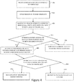
Figure 4 is a flowchart illustrating a method of utilizing shadows to detect vacant parking spots according to some embodiments. -
Figure 5a is a photograph of a parking aisle captured by one or more sensors on the vehicle being parked prior to proceeding down an aisle;Figure 5b is a magnified view of the parking aisle;Figure 5c is a computer vision image of the photograph identifying shadows with white pixels and non-shadows with black pixels according to some embodiments; andFigure 5d is a computer vision image of the photograph illustrating shadow measurements according to some embodiments. - According to some embodiments, a method of detecting vacant parking location within a parking lot includes receiving sensor data captured with respect to the parking lot (e.g., parking aisle). The sensor data - such as camera and/or infrared images - are utilized to detect the presence of shadows cast by the parked vehicles. For example, a variety of methods (e.g., color-based, texture-based, intensity-based, etc.) may be utilized to detect the presence of shadows within an image. Likewise, infrared images may be utilized to detect shadows based on differences in temperature resulting from the presence of shadows. Vacant parking spots are detected based on analysis of the detected shadows - in particular analysis of the gaps between adjacent shadows. If a vacant parking spot is detected, the vehicle may proceed down the aisle to the detected vacancy. If no vacant parking spot is detected, then the vehicle may proceed to the next aisle and repeat the process. A benefit of the system and method described herein is that the vehicle may be able to detect parking spot vacancies without being required to proceed down each aisle to a location adjacent to the vacancy.
- Referring to
Figures 1a and1b , a top view of aparking lot 100 is shown, wherein the parking lot includes afirst aisle 104a and asecond aisle 104b. With respect to thefirst aisle 104a, a first plurality ofvehicles 108a-108h (collectively, vehicles 108) are parked adjacent to the aisle. With respect to the second aisle, a second plurality ofvehicles 109 are parked in the aisle. For purposes of this discussion, it is assumed that the parking spots occupied by the first plurality of vehicles 108 may be accessed only through thefirst aisle 104a and the parking spots occupied by the second plurality ofvehicles 109 may be accessed only through thesecond aisle 104b. In other parking lots, parking spots occupied by the second plurality ofvehicles 109 may be accessed via thefirst aisle 104a. As described later, information regarding the layout and rules of the parking lot may be utilized by the systems and methods described herein. - In the example shown in
Figure 1a , aparking spot vacancy 110 is located betweenparked vehicles vehicle 106, this vacancy is occluded by the presence of the plurality ofvehicles 108a-108f. In some embodiments, although theparking spot 110 is occluded from view,shadows 112a-112h (seeFigure 1b ) cast by the plurality of parkedvehicles 108a-108h, respectively, may be detected along with the lack of shadow - shadow vacancy 114 - and utilized to detectparking vacancy 110. In the embodiment shown inFigures 1a and1b , shadows are cast by thesun 107, but in other embodiments may be cast by other sources of light. A benefit of this approach is that the detection ofparking vacancy 110 may be made from the end of theaisle 104a as shown inFigure 1b . That is, thevehicle 106 is not required to traverse theaisle 104a to a position adjacent to theparking vacancy 110 in order to detect the vacancy. In the event a determination is made that the aisle does not include any parking vacancies (i.e., confirms that each of the parking spots are occupied), thevehicle 106 proceeds to the next aisle (e.g.,aisle 104b) and performs the same search. In some embodiments, if a determination cannot be made that each of the parking spots are occupied - for example, due to time of day, cloud cover, etc. - then in some embodiments the vehicle may default to continuing down the aisle and checking for vacancies using other sensors. - In some embodiments,
vehicle 106 includes one or more first sensors (not shown) utilized to detect the presence of objects (e.g.., vehicles) and one or more second sensors utilized to detect the presence of or effects of shadows. For example, in some embodiments the one or more first sensors utilized to detect the presence of adjacent vehicles includes one or more of LiDAR sensors, radar sensors, and/or cameras. In some embodiments, the one or more second sensors utilized to detect the presence of or effects of shadows includes one or more of cameras and infrared sensors. In some embodiments, the same sensor utilized to detect the presence of vehicles may also be utilized to detect the presence or lack thereof of shadows. For example, a camera-based sensor may be utilized to both detect the presence of vehicles and detect the presence of shadows. - Referring to
Figures 2 and3 , a system and method of detecting vacant parking spots is provided. In particular,Figure 2 is a block diagram illustrating a parking vacancy detection system that utilizes shadow detection to detect vacant parking spots according to some embodiments.Figure 3 is a flowchart illustrating steps implemented to detect vacant parking spots based on detected shadows. - According to some embodiments, the parking vacancy detection system 200 is deployed on a vehicle being parked autonomously or semi-autonomously and includes one or more sensors, including one or more of
vehicle detection sensors 202,shadow detection sensors 204, andorientation sensors 206, and a processor/controller 208. In some embodiments, the vehicle detection sensor includes one or more of LiDAR sensors, radar sensors, cameras, and/or other sensors capable of detecting the presence of objects/vehicles within the vicinity of the vehicle being parked. In some embodiments, theshadow detection sensors 204 include one or more cameras and/or infrared sensors capable of detecting the presence of shadows. In some embodiments, anorientation sensor 206 provides input to the parking vacancy detection system 200 regarding the orientation of the vehicle to be parked, wherein theorientation sensor 206 includes one or more of an inertial measurement unit (IMU), accelerometers, etc. In some embodiments, some of the sensors utilized for vehicle detection are also utilized for shadow detection. For example, cameras may be utilized for both vehicle detection and shadow detection. - In some embodiments, processor/
controller 208 receives inputs from one or more of the sensors and utilizes the received inputs to detect parking vacancies. In some embodiments,processor controller 208 may additionally receive inputs from other sources, such as map information provided with respect to a parking facility and/or inputs regarding the weather and/or location of the sun. As described in more detail below, in some embodiments these inputs are utilized to make determinations regarding whether shadows are present and if so, the likely direction in which shadows will be cast. For example, information regarding the location of artificial lights within indoor and outdoor (at least at night) parking facilities may be utilized to determine the likely location of shadows cast by parked vehicles. Likewise, the location/orientation of the sun may similarly be utilized to determine the likely location of shadows cast by parked vehicles. - In some embodiments, processor/
controller 208 utilizes the received inputs to detect parking vacancies and to provide an output utilized by the semi-autonomous or autonomous vehicle to assist in self-park operations. For example, detection of a parking vacancy may result in the semi-autonomous or autonomous vehicle proceeding down the aisle to the parking vacancy detected. Alternatively, a determination that the aisle does not include any parking vacancies may result in the semi-autonomous or autonomous vehicle proceeding to the next aisle, wherein the process is repeated. In some embodiments, the determination that an aisle does not include any parking vacancies is not simply a determination that no vacancies were detected, but rather a determination than all parking spots are occupied. In the case that it can be determined that all spots are in fact occupied, then the autonomous vehicle may proceed to the next aisle, saving the cost associated with travel down the occupied aisle. - For example, the flowchart provided with respect to
Figure 3 illustrates steps performed as part of the semi-autonomous or autonomous vehicles according to some embodiments. Atstep 302, the vehicle proceeds to an aisle. In the example shown inFigure 1b ,vehicle 106 proceeds first toaisle 104a. More particularly, the vehicle proceeds to a first position located at the start or head of the aisle, with sensors oriented in the direction of vehicles parked along the adjacent aisle. - At
step 304, one or more first sensors are utilized to detect the presence of parked vehicles in the aisle. For example, in the embodiment shown inFigure 1a , processor/controller 208 utilizes inputs received from one or morevehicle detection sensors 202 to determine whetheraisle 104a includes the presence of parkedvehicles 108a-108h. In the event that theparking aisle 104a does not include any parked vehicles, then the method proceeds to step 312 in which the vehicle proceeds down the aisle and parks. In this instance, no analysis of shadows is required - and in fact because no vehicles are parked in the aisle no shadows will be cast. That is, no determination can be made that all parking spots are occupied. In the example shown inFigure 1a , a sensor generates aLiDAR signal 111 that reflects off ofadjacent vehicle 108a and is utilized to detect the presence of at least one vehicle inparking aisle 104a. - At
step 306, a determination is made whether shadows may be utilized to detect the presence of vacant parking spots. In some embodiments, this determination may be made based on one or more of a plurality of factors. For example, in some embodiments the time of day may be utilized to determine whether it is likely that shadows will be generated (e.g., if at night, shadows will not be cast by the sun). In some embodiments, the weather (e.g., cloudy, sunny) may be utilized to determine the likelihood of shadows being cast. In some embodiments, shadows cast by artificial light may be utilized in the event information is available regarding the presence of artificial light sources and assuming a time of day that would utilize artificial light sources. - In other embodiments, the determination of whether shadows are being cast may further include whether shadows are being cast in a way that is useful for detecting vacancies. This may include utilizing information regarding the location of a light source (e.g., sun, artificial sources, etc.) relative to a parking aisle and the resulting direction in which shadows will be cast. This may also require information regarding the orientation of the vehicle as provided by
orientation sensor 206 shown inFigure 2 . - If at step 306 a determination is made that shadows cannot be utilized to detect the presence of vacant parking spots, then the vehicle is instructed to traverse down the aisle at
step 312 and to utilize one or more sensors to detect the presence of a vacant parking spot. If at step 306 a determination is made that shadows can be utilized to detect the presence of vacant parking spots, then the method proceeds to step 308. - At
step 308, the one or more sensors are utilized to detect the presence of shadows. A number of methods may be utilized to detect the presence of shadows. For example, in some embodiments the input is an image such as those shown inFigures 5a and 5b , whereinFigure 5b illustrates a magnified view of the image shown inFigure 5a . The presence of shadows is detected using one or more computer-vision techniques, such as color-based, texture-based, geometric-based, and/or intensity-based techniques. For example, intensity-based techniques compare the intensity of adjacent pixels, wherein pixels associated with shadows will illustrate a reduction in intensity. This is evident with respect toFigure 5b , in which pixels located in shadows display an intensity significantly less than adjacent pixels receiving direct sunlight. In some embodiments, either alone or in combination with intensity-based techniques, color-based techniques may be utilized, wherein color-based techniques rely on spectral features of the pixels to detect the presence of shadows. For example, in some embodiments shifts in the frequency of light (e.g., color) are utilized to detect shadows, wherein a shift towards the blue spectrum indicates a possible shadow as a result of white light from the sun being blocked without blocking blue light reflected from the sky. In some embodiments, a combination of intensity and color-based techniques are utilized, wherein pixels located within shadows can be expected to display lower intensity without a corresponding change in color. The combination of both features may be utilized to detect shadow pixels. In still other embodiments, knowledge of the location of illumination sources (e.g., both natural and artificial) and the likely geometry of objects (e.g., vehicles) casting shadows is utilized to determine the expected geometry of shadows being cast. In still other embodiments, texture-based methods are utilized, wherein during a first stage pixels are identified as being potential shadow pixels (using any number of techniques) and in a second stage the texture of shadow pixels are compared to the texture of a background reference image, wherein if the texture is similar the pixels are identified as shadow pixels. In still other embodiments, other computer vision techniques may be utilized to detect the presence of shadows. - In other embodiments, other types of sensor inputs may be utilized, such as infrared inputs. Infrared sensors detect temperature and may be utilized in outdoor parking lots during the day in which the presence of shadows will result in a temperature differential capable of detection. In still other embodiments, other indications of the presence and/or absence of vehicles may be utilized. For example, the presence of dry pavement (adjacent to vehicles) and wet pavement (resulting from a lack of shielding from a vehicle) may be utilized to detect vacant parking spots.
- At
step 308, if no shadows are detected using one or more sensors - but fromstep 304 we know that vehicles are parked in the aisle - then shadows will not be available to detect the presence of vacancies and the vehicle will be required to drive down the parking aisle atstep 312. If atstep 308 one or more shadows are detected, then a determination is made that shadows can be utilized to detect the presence or absence of parking vacancies and the method proceeds to step 310. - At
step 310 the vehicle shadows detected atstep 308 are utilized to detect parking vacancies. In particular, gaps or spaces in the detected shadows of the appropriate size, shape, etc. are utilized to detect a parking vacancy (or conversely the lack of gaps or spaces are utilized to determine that all parking spots are occupied). For example, referring to the example shown inFigure 1b , a plurality ofshadows 112a-1 12f and 112g-112h are detected, each shadow indicating the presence of a parked vehicle. Analysis of the detected shadows (i.e., array of shadows) indicates an absence of a shadow corresponding withlocation 114. This gap in the array of detected shadows, specifically the gap detected between shadows 112f and 112g indicates the presence of a parking spot vacancy atlocation 110. In this way, the determination atstep 310 may be viewed as a detection of missing shadows indicative of a vacant parking spot, or detection of parked vehicles indicating the presence of a parked vehicle. - If no missing shadows are detected at
step 310, then an output is generated indicating that this aisle does not include any parking vacancies and atstep 302 the vehicle is instructed to proceed to the next parking aisle and repeat the process. In some embodiments, the determinations atsteps step 310 that no missing shadows are detected may also be considered a determination that all parking spots in the aisle are occupied. In particular, the determination atstep 310 that all parking spots are occupied prevents the vehicle from having to drive down the parking aisle - and potentially back up the parking aisle if no spot exists. If a missing shadow indicative of a parking vacancy is detected atstep 310, then an output is generated indicating the presence of a vacancy and the vehicle proceeds to travel down the parking aisle. - At
step 314 one or more sensors are utilized to detect the vacancy identified by the missing shadows. For example, in some embodiments the one or more sensors are the same one or more sensors utilized to detect vehicles atstep 304. In some embodiments, the one or more sensors include LiDAR sensors, radar sensors, ultrasonic sensors and/or cameras utilized to detect a parking spot vacancy. In the event no parking spot vacancy is detected (e.g., false positive detected based on the shadows) then an output is generated indicating the false event and the vehicle is instructed to proceed to the next aisle atstep 302. In some embodiments, analysis may be performed to determine what caused the false positive event and may be provided in feedback to prevent the same root cause from causing future false positives. - If at step 314 a vacancy is detected based on the one or more sensors, then at
step 316 outputs are generated to cause the autonomous or semi-autonomous vehicle to park within the vacancy and the process ends. - Referring now to
Figure 4 , additional detail regarding analysis performed to detect parking vacancies is provided according to some embodiment. Atstep 401, sensor data is received with respect to the adjacent parking aisle. As discussed above, this may include image data captured by a camera and/or infrared data captured by an infrared sensor. Atstep 402 the received sensor data is utilized to detect the presence of shadows. For example, in the embodiment shown inFigure 5c , computer vision techniques (such as those described above) are utilized to detect shadows (indicated by white portions - with non-shadow pixels indicated in black). - At
step 403, one or more attributes associated with the detected shadows are measured. In some embodiments, measured attributes may include one or more of shadow length, shadow width, length-to-width ratio, and/or angle of the created shadows. In some embodiments, measured attributes are provided with respect to each shadow attributed to a particular vehicular shadow. For example, in the embodiment shown inFigure 5c , a plurality of shadows (indicated by the white pixels) have been detected, each shadow separated from an adj acent shadow by a sliver of light (shown in black). Detected shadows includeshadow shadows Figure 5d , measured attributes include length and width of each of the plurality of detected shadows. In some embodiments, at least some of the attributes may be measured based on counting pixels associated with detected shadows. However, as shown inFigures 5c and 5d , the further away the shadow is located from the sensor, the smaller the shadow will appear. In some embodiments, rather than simply count pixels, the distance from the sensor is determined and utilized to convert the counted pixels into actual lengths and widths. That is, rather than expressshadow 500a in terms of a number of pixels long by a number of pixels wide, an actual length and width of theshadow 500a is calculated. - At
step 404, the measured attributes are utilized to determine whether the detected shadows are indicative of parked vehicles. For example, in some embodiments based on knowledge of the location of the illumination source (e.g., sun, lights), and expected dimensions of vehicles, expected shadow lengths/widths, length-to-width ratios, etc. can be determined. If at step 404 a determination is made that the detected shadows are not cast by one or more vehicles, then at step 406 a determination is made that the shadows cannot be used to detect vacancies. In response, the vehicle may be required to travel down the aisle and detect vacancies using other sensors. If at step 404 a determination is made that the detected shadows are cast by one or more vehicles, this indicates that the shadows can be utilized to detect vacancies, and the method continues atstep 408 to use the measured attributes to define thresholds for detecting vacancies. - At
step 408 one or more thresholds are generated based on the one or more measured attributes to determine whether a gap between adjacent shadows is indicative of a vacancy. In some embodiments, a plurality of thresholds or dynamic thresholds are defined based on the location of the shadows. Once again, the threshold may be expressed in the form of pixels, distances, ratios or angle thresholds depending on how the detected shadows are expressed. In some embodiments, for shadows or gaps in shadows located close to the vehicle, the number of pixels associated with a vehicle shadow or gap may be larger than the number of pixels associated with a vehicle shadow or gap located further down the aisle. For example, this is illustrated inFigure 5d , in which the size of the shadows decrease the further down the aisle the shadows are located. In some embodiments, the threshold is utilized to assess the width of the gap between adjacent shadows. For example, in the embodiments shown inFigure 5c and 5d , a gap exists between each of the detectedshadows shadows step 408 is utilized to assess which of these gaps is indicative of a parking vacancy. In some embodiments, a threshold is generated with respect to each pair of adjacent shadows. For example, the width ofshadows shadows shadows shadows - At
step 410, the threshold(s) generated atstep 408 are compared to gaps between adjacent shadows to detect vacant parking spots. In some embodiments, parking vacancies are detected in response to the gap between adjacent shadows being greater than the defined threshold. For example, in the embodiment shown inFigure 5d , the gap betweenshadows step 410 than atstep 412 an output is generated indicating that no vacant parking spots have been detected, and that the vehicle should proceed to the next aisle rather than traveling down the current aisle. If vacancies are detected atstep 410, then atstep 414 an output is generated indicating that a vacancy has been detected and instructing the vehicle to proceed down the current aisle to the detected vacancy. - In this way, the present disclosure provides a system and method of detecting vacant parking spots based on detected shadows (i.e., detecting that each parking spot is occupied). A benefit of the system and method described herein is that the vehicle is able to detect in some cases if each parking spot in an aisle is occupied and therefore prevents the vehicle from having to traverse these aisles.
- While the invention has been described with reference to an exemplary embodiment(s), it will be understood by those skilled in the art that various changes may be made and equivalents may be substituted for elements thereof without departing from the scope of the invention. In addition, many modifications may be made to adapt a particular situation or material to the teachings of the invention without departing from the essential scope thereof. Therefore, it is intended that the invention not be limited to the particular embodiment(s) disclosed, but that the invention will include all embodiments falling within the scope of the appended claims.
- The following are non-exclusive descriptions of possible embodiments of the present invention.
- According to one aspect, a method of identifying vacant parking locations may include receiving sensor data captured with respect to a parking aisle and analyzing the received sensor data to detect shadows cast by parked vehicles within the parking aisle. Vacancies may be detected based on the detected shadows and an output generated indicating whether a parking spot vacancy has been detected.
- The method of the preceding paragraph can optionally include, additionally and/or alternatively any, one or more of the following features, configurations and/or additional components.
- According to some embodiments, the sensor data is image data captured by a camera.
- According to some embodiments, the sensor data is thermal data captured by an infrared camera.
- According to some embodiments, the method may further include measuring one or more attributes of detected shadows.
- According to some embodiments, measuring one or more attributes of detected shadows includes measuring one or more of shadow length, shadow width, length-to-width ratio, and angle-of-shadow.
- According to some embodiments, the method may further include generating a threshold(s) utilized to determine whether a gap between adjacent shadows in indicative of a parking spot vacancy based on the one or more measured attributes.
- According to some embodiments, detecting a vacant parking spot based on the detected shadows may further include comparing a gap between adjacent shadows to the generated threshold(s).
- According to another aspect, a method of self-parking a vehicle within a parking lot may include positioning the vehicle at a first end of a first aisle and detecting shadows in the aisle using input received from one or more first sensors. The method may further include detecting parked vehicles based on the detected shadows, wherein if all parking spots are occupied the vehicle is instructed to proceed directly to the next aisle.
- The method of the preceding paragraph can optionally include, additionally and/or alternatively any, one or more of the following features, configurations and/or additional components.
- According to some embodiments, the method may further include detecting a presence of parked vehicles using input received from one or more second sensors, wherein if no parked vehicles are detected the vehicle is instructed to proceed down the first aisle.
- According to some embodiments, the method may further include determining based on one or more inputs whether shadows are available for detection, wherein the one or more inputs includes one or more of time of day, and weather, position/angle of the sun.
- According to some embodiments, if shadows are not available for detection the vehicle is instructed to proceed down the first aisle.
- According to some embodiments, the method may further include measuring one or more attributes of detected shadows, wherein the one or more measured attributes include one or more of shadow length, shadow width, length-to-width ratio, and angle-of-shadow.
- According to some embodiments, the method may further include generating a threshold(s) utilized to determine whether a gap between adjacent shadows is indicative of a parking spot vacancy based on the one or more measured attributes.
- According to some embodiments, detecting a vacant parking spot based on the detected shadows may include comparing a gap between adjacent shadows to the generated threshold(s).
- According to another aspect, a parking vacancy detection system for use in vehicles may include a first plurality of sensors configured to detect image data associated with a parking aisle located adjacent to the vehicle and a processor/controller configured to receive the image data detected by the first plurality of sensors. In some embodiments, the processor/controller is configured to detect shadows based on the received image data and to detect vacant parking spots based on detected gaps within the detected shadows, wherein the processor/controller generates an output identifying whether the parking aisle includes vacant parking spots.
- The system of the preceding paragraph can optionally include, additionally and/or alternatively any, one or more of the following features, configurations and/or additional components.
- For example, in some embodiments the system may further include a second plurality of sensors, wherein the second plurality of sensors are configured to detect the presence of parked vehicles and wherein the processor/controller utilizes the detected presence of parked vehicles to determine whether shadows can be utilized to detect vacant parking spots.
- According to some embodiments the processor/controller is configured to receive input from one or more external sources regarding the presence of and orientation of a light source, wherein the processor/controller utilizes the received input to determine whether shadows can be utilized to detect vacant parking spots.
- According to some embodiments, the processor/controller is configured to receive orientation data from one or more orientation sensors, wherein the processor/controller utilizes the received orientation data in combination with input from one or more external sources regarding the presence of and orientation of a light source to determine a likely location of shadows cast in response to parked vehicles.
- According to some embodiments, the processor/controller may measure one or more attributes of detected shadows.
- According to some embodiments, the processor/controller may measure one or more of shadow length, shadow width, length-to-width ratio, and angle-of-shadow and generates a threshold utilized to determine whether a gap between adjacent shadows in indicative of a parking spot vacancy based on the one or more measured attributes.
Claims (16)
- A method of identifying vacant parking locations, the method comprising:receiving sensor data captured with respect to a parking aisle (step 401);analyzing the received sensor data to detect shadows cast by parked vehicles within the parking aisle (step 402);detecting a vacant parking spot based on the detected shadows (step 410); and generating an output indicating whether a parking spot vacancy has been detected within the parking aisle (step 412, 414).
- The method of claim 1, wherein the sensor data includes one of image data captured by a camera or thermal data captured by an infrared camera.
- The method of claim 1 or 2, further including measuring one or more attributes of the detected shadows (step 403), wherein measuring one or more attributes of detected shadows includes measuring one or more attributes of detected shadows includes measuring one or more of shadow length, shadow width, length-to-width ratio, and angle-of-shadow (step 403).
- The method of claim 3, further including generating a threshold(s) utilized to determine whether a gap between adjacent shadows is indicative of a parking spot vacancy based on the one or more measured attributes (step 408).
- The method of claim 4, wherein detecting a vacant parking spot based on the detected shadows includes comparing the gap between the adjacent shadows to the generated threshold(s) (step 410).
- A method of self-parking a vehicle within a parking lot, the method comprising:positioning the vehicle at a first end of a first aisle (302);detecting shadows in the aisle using input received from one or more first sensors (step 308); anddetecting parked vehicles based on the detected shadows (step 310), wherein if all parking spots are occupied the vehicle is instructed to proceed directly to a next aisle (step 302).
- The method of claim 6, further including:detecting a presence of parked vehicles using input received from one or more second sensors (step 304), wherein if no parked vehicles are detected the vehicle is instructed to proceed down the first aisle (step 312).
- The method of claim 6 or 7, further including:determining based on one or more inputs whether shadows are available for detection, wherein the one or more inputs includes one or more of time of day, and weather, and position/angle of the sun (step 306), wherein if shadows are not available for detection the vehicle is instructed to proceed down the first aisle (step 312).
- The method of any one of claims 6 to 8, further including:measuring one or more attributes of detected shadows, wherein the one or more measured attributes include one or more of shadow length, shadow width, length-to-width ratio, and angle-of-shadow (step 403).
- The method of claim 12, further including generating a threshold(s) utilized to determine whether a gap between adjacent shadows in indicative of a parking spot vacancy based on the one or more measured attributes (step 408), wherein detecting a vacant parking spot based on the detected shadows includes comparing a gap between adjacent shadows to the generated threshold(s) (step 410).
- The method of claim 10, wherein detecting a vacant parking spot based on the detected shadows includes comparing a gap between adjacent shadows to the generated threshold(s) (step 410).
- A parking vacancy detection system for use in a vehicle, the system comprising:a first plurality of sensors (204) configured to detect image data associated with a parking aisle located adjacent to the vehicle; anda processor/controller (208) configured to receive the image data detected by the first plurality of sensors (204), wherein the processor/controller (208) is configured to detect shadows based on the received image data and to detect vacant parking spots based on detected gaps within the detected shadows, wherein the processor/controller generates an output identifying whether the parking aisle includes vacant parking spots.
- The system of claim 12, further including a second plurality of sensors (202), wherein the second plurality of sensors (202) is configured to detect the presence of parked vehicles, wherein the processor/controller (208) utilizes the detected presence of parked vehicles to determine whether shadows can be utilized to detect vacant parking spots.
- The system of claim 12 or 13, wherein the processor/controller (208) is configured to receive input from one or more external sources regarding the presence of and orientation of a light source, wherein the processor/controller (208) utilizes the received input to determine whether shadows can be utilized to detect vacant parking spots.
- The system of claim 14, wherein the processor/controller (208) is configured to receive orientation data from one or more orientation sensors (206), wherein the processor/controller (208) utilizes the received orientation data in combination with input from one or more external sources regarding the presence of and orientation of a light source to determine a likely location of shadows cast in response to parked vehicles.
- The system of any one of claims 12 to 15, wherein the processor/controller (208) measures one or more attributes of detected shadows, wherein measured attributes include one or more of shadow length, shadow width, length-to-width ratio, and angle-of-shadow and generates a threshold utilized to determine whether a gap between adjacent shadows in indicative of a parking spot vacancy based on the one or more measured attributes.
Applications Claiming Priority (1)
| Application Number | Priority Date | Filing Date | Title |
|---|---|---|---|
| US16/824,882 US11328607B2 (en) | 2020-03-20 | 2020-03-20 | System and method of detecting vacant parking spots |
Publications (2)
| Publication Number | Publication Date |
|---|---|
| EP3882886A1 true EP3882886A1 (en) | 2021-09-22 |
| EP3882886B1 EP3882886B1 (en) | 2024-08-21 |
Family
ID=74874656
Family Applications (1)
| Application Number | Title | Priority Date | Filing Date |
|---|---|---|---|
| EP21162477.0A Active EP3882886B1 (en) | 2020-03-20 | 2021-03-15 | System and method of detecting vacant parking spots |
Country Status (3)
| Country | Link |
|---|---|
| US (2) | US11328607B2 (en) |
| EP (1) | EP3882886B1 (en) |
| CN (2) | CN113496617B (en) |
Cited By (1)
| Publication number | Priority date | Publication date | Assignee | Title |
|---|---|---|---|---|
| WO2024115493A1 (en) * | 2022-11-28 | 2024-06-06 | Sony Semiconductor Solutions Corporation | Electronic device and method |
Families Citing this family (3)
| Publication number | Priority date | Publication date | Assignee | Title |
|---|---|---|---|---|
| US11328607B2 (en) * | 2020-03-20 | 2022-05-10 | Aptiv Technologies Limited | System and method of detecting vacant parking spots |
| US11756311B2 (en) * | 2021-05-18 | 2023-09-12 | Toyota Motor Engineering & Manufacturing North America, Inc. | Parking spot and person detection |
| EP4113460A1 (en) * | 2021-06-29 | 2023-01-04 | Ford Global Technologies, LLC | Driver assistance system and method improving its situational awareness |
Citations (3)
| Publication number | Priority date | Publication date | Assignee | Title |
|---|---|---|---|---|
| DE102017007210A1 (en) * | 2017-07-28 | 2018-03-01 | Daimler Ag | Fahrzeugeinparksteuerungssystem |
| US20190339706A1 (en) * | 2017-06-12 | 2019-11-07 | Faraday&Future Inc. | System and method for detecting occluded objects based on image processing |
| US20200042801A1 (en) * | 2018-07-31 | 2020-02-06 | Toyota Motor Engineering & Manufacturing North America, Inc. | Object detection using shadows |
Family Cites Families (22)
| Publication number | Priority date | Publication date | Assignee | Title |
|---|---|---|---|---|
| US4931930A (en) | 1988-04-19 | 1990-06-05 | Industrial Technology Research Institute | Automatic parking device for automobile |
| US7720580B2 (en) * | 2004-12-23 | 2010-05-18 | Donnelly Corporation | Object detection system for vehicle |
| EP1701323A1 (en) * | 2005-02-28 | 2006-09-13 | Alcatel | Method for detecting a parking place |
| CN101414411B (en) * | 2007-10-17 | 2010-08-25 | 财团法人工业技术研究院 | Image-based vacancy detection system and method |
| JPWO2009060663A1 (en) | 2007-11-08 | 2011-03-17 | ボッシュ株式会社 | Parking assistance device |
| US7932835B2 (en) | 2008-01-25 | 2011-04-26 | Delphi Technologies, Inc. | Vehicle zone detection system and method |
| JP2010117800A (en) * | 2008-11-11 | 2010-05-27 | Toshiba It & Control Systems Corp | Parking lot monitoring device and method |
| US10081308B2 (en) * | 2011-07-08 | 2018-09-25 | Bendix Commercial Vehicle Systems Llc | Image-based vehicle detection and distance measuring method and apparatus |
| DE102012201891A1 (en) | 2012-02-09 | 2013-08-14 | Robert Bosch Gmbh | Parking assistance method and parking assistance system for determining a parking space |
| JP5867167B2 (en) * | 2012-03-05 | 2016-02-24 | 日産自動車株式会社 | Shadow detection device |
| DE102013004073A1 (en) * | 2013-03-11 | 2014-09-11 | Martin Vorbach | Video stream analysis |
| IL238473A0 (en) * | 2015-04-26 | 2015-11-30 | Parkam Israel Ltd | A method and system for detecting and mapping parking spaces |
| DE102015209147A1 (en) * | 2015-05-19 | 2016-11-24 | Hella Kgaa Hueck & Co. | Method for parking area detection |
| EP3324382A1 (en) * | 2016-11-22 | 2018-05-23 | Continental Automotive GmbH | System and method for vehicle parking assistance |
| US10369988B2 (en) | 2017-01-13 | 2019-08-06 | Ford Global Technologies, Llc | Autonomous parking of vehicles inperpendicular parking spots |
| JP6720931B2 (en) * | 2017-07-14 | 2020-07-08 | 株式会社デンソー | Vehicle surrounding recognition device |
| US10586452B2 (en) * | 2017-10-15 | 2020-03-10 | Lenovo (Singapore) Pte. Ltd. | Transmission of parking instructions with clearance distances to self-driving vehicles |
| CN109918977B (en) * | 2017-12-13 | 2021-01-05 | 华为技术有限公司 | Method, device and equipment for determining idle parking space |
| US10919522B2 (en) * | 2018-06-13 | 2021-02-16 | Fujitsu Limited | Automated exploitation of shade-giving structures |
| JP7087926B2 (en) * | 2018-11-05 | 2022-06-21 | トヨタ自動車株式会社 | Parking support device |
| US20210049383A1 (en) * | 2019-08-13 | 2021-02-18 | Urbn, Inc. | System And Method For Determining Parking Space Vacancy Using Solar Irradiance |
| US11328607B2 (en) * | 2020-03-20 | 2022-05-10 | Aptiv Technologies Limited | System and method of detecting vacant parking spots |
-
2020
- 2020-03-20 US US16/824,882 patent/US11328607B2/en active Active
-
2021
- 2021-03-15 EP EP21162477.0A patent/EP3882886B1/en active Active
- 2021-03-18 CN CN202110292222.5A patent/CN113496617B/en active Active
- 2021-03-18 CN CN202311529738.2A patent/CN117542222A/en active Pending
-
2022
- 2022-05-09 US US17/739,905 patent/US12412477B2/en active Active
Patent Citations (3)
| Publication number | Priority date | Publication date | Assignee | Title |
|---|---|---|---|---|
| US20190339706A1 (en) * | 2017-06-12 | 2019-11-07 | Faraday&Future Inc. | System and method for detecting occluded objects based on image processing |
| DE102017007210A1 (en) * | 2017-07-28 | 2018-03-01 | Daimler Ag | Fahrzeugeinparksteuerungssystem |
| US20200042801A1 (en) * | 2018-07-31 | 2020-02-06 | Toyota Motor Engineering & Manufacturing North America, Inc. | Object detection using shadows |
Cited By (1)
| Publication number | Priority date | Publication date | Assignee | Title |
|---|---|---|---|---|
| WO2024115493A1 (en) * | 2022-11-28 | 2024-06-06 | Sony Semiconductor Solutions Corporation | Electronic device and method |
Also Published As
| Publication number | Publication date |
|---|---|
| CN117542222A (en) | 2024-02-09 |
| US12412477B2 (en) | 2025-09-09 |
| CN113496617A (en) | 2021-10-12 |
| US20220262255A1 (en) | 2022-08-18 |
| US11328607B2 (en) | 2022-05-10 |
| EP3882886B1 (en) | 2024-08-21 |
| CN113496617B (en) | 2023-12-05 |
| US20210295704A1 (en) | 2021-09-23 |
Similar Documents
| Publication | Publication Date | Title |
|---|---|---|
| EP3882886B1 (en) | System and method of detecting vacant parking spots | |
| US11175406B2 (en) | Range imaging system and solid-state imaging device | |
| JP3275620B2 (en) | Automatic billing system | |
| US8041079B2 (en) | Apparatus and method for detecting obstacle through stereovision | |
| US11674907B2 (en) | Method and device for recognising and analysing surface defects in three-dimensional objects having a reflective surface, in particular motor vehicle bodies | |
| JPH08329393A (en) | Leading vehicle detection device | |
| JP2021514457A (en) | Rain filtering techniques for autonomous vehicles | |
| US20200050865A1 (en) | Method and system for detecting a raised object located within a parking area | |
| JP7103324B2 (en) | Anomaly detection device for object recognition and anomaly detection program for object recognition | |
| CN102589515B (en) | Foggy-weather distance measurement method and device thereof as well as distance pre-warning method and device thereof | |
| CN117238143B (en) | Traffic data fusion method, system and device based on radar double-spectrum camera | |
| JP3363763B2 (en) | Vehicle type determination method and device | |
| JP7043787B2 (en) | Object detection system | |
| CN118061900A (en) | Vehicle lighting control method, device, electronic device and readable storage medium | |
| CN106127736A (en) | One is parked detection method and processor | |
| JP2007310574A (en) | Collision risk determination system and warning system | |
| US20240061092A1 (en) | Sensor system | |
| US20160231243A1 (en) | System and method for remotely sensing visible ray transmittance of vehicle window | |
| US11503217B2 (en) | System and method of estimating ambient light | |
| JP2007115191A (en) | Vehicle sensing system, inspection device, and inspection method | |
| JPH10293897A (en) | Vehicle shape discriminator | |
| JPH09212791A (en) | Method and device for monitoring road surface | |
| JP2894338B1 (en) | Vehicle detector | |
| TWI750673B (en) | System of estimating ambient light | |
| WO2011093767A1 (en) | A vision system and method for a motor vehicle |
Legal Events
| Date | Code | Title | Description |
|---|---|---|---|
| PUAI | Public reference made under article 153(3) epc to a published international application that has entered the european phase |
Free format text: ORIGINAL CODE: 0009012 |
|
| STAA | Information on the status of an ep patent application or granted ep patent |
Free format text: STATUS: THE APPLICATION HAS BEEN PUBLISHED |
|
| AK | Designated contracting states |
Kind code of ref document: A1 Designated state(s): AL AT BE BG CH CY CZ DE DK EE ES FI FR GB GR HR HU IE IS IT LI LT LU LV MC MK MT NL NO PL PT RO RS SE SI SK SM TR |
|
| STAA | Information on the status of an ep patent application or granted ep patent |
Free format text: STATUS: REQUEST FOR EXAMINATION WAS MADE |
|
| 17P | Request for examination filed |
Effective date: 20220318 |
|
| RBV | Designated contracting states (corrected) |
Designated state(s): AL AT BE BG CH CY CZ DE DK EE ES FI FR GB GR HR HU IE IS IT LI LT LU LV MC MK MT NL NO PL PT RO RS SE SI SK SM TR |
|
| RAP3 | Party data changed (applicant data changed or rights of an application transferred) |
Owner name: APTIV TECHNOLOGIES LIMITED |
|
| GRAP | Despatch of communication of intention to grant a patent |
Free format text: ORIGINAL CODE: EPIDOSNIGR1 |
|
| STAA | Information on the status of an ep patent application or granted ep patent |
Free format text: STATUS: GRANT OF PATENT IS INTENDED |
|
| RIC1 | Information provided on ipc code assigned before grant |
Ipc: G06V 20/58 20220101ALI20240216BHEP Ipc: G08G 1/14 20060101ALI20240216BHEP Ipc: G08G 1/16 20060101AFI20240216BHEP |
|
| INTG | Intention to grant announced |
Effective date: 20240314 |
|
| RAP1 | Party data changed (applicant data changed or rights of an application transferred) |
Owner name: APTIV TECHNOLOGIES AG |
|
| GRAS | Grant fee paid |
Free format text: ORIGINAL CODE: EPIDOSNIGR3 |
|
| GRAA | (expected) grant |
Free format text: ORIGINAL CODE: 0009210 |
|
| STAA | Information on the status of an ep patent application or granted ep patent |
Free format text: STATUS: THE PATENT HAS BEEN GRANTED |
|
| P01 | Opt-out of the competence of the unified patent court (upc) registered |
Free format text: CASE NUMBER: APP_39000/2024 Effective date: 20240701 |
|
| AK | Designated contracting states |
Kind code of ref document: B1 Designated state(s): AL AT BE BG CH CY CZ DE DK EE ES FI FR GB GR HR HU IE IS IT LI LT LU LV MC MK MT NL NO PL PT RO RS SE SI SK SM TR |
|
| REG | Reference to a national code |
Ref country code: GB Ref legal event code: FG4D |
|
| REG | Reference to a national code |
Ref country code: CH Ref legal event code: EP |
|
| REG | Reference to a national code |
Ref country code: DE Ref legal event code: R096 Ref document number: 602021017374 Country of ref document: DE |
|
| REG | Reference to a national code |
Ref country code: IE Ref legal event code: FG4D |
|
| RAP4 | Party data changed (patent owner data changed or rights of a patent transferred) |
Owner name: APTIV TECHNOLOGIES AG |
|
| REG | Reference to a national code |
Ref country code: LT Ref legal event code: MG9D |
|
| REG | Reference to a national code |
Ref country code: NL Ref legal event code: MP Effective date: 20240821 |
|
| PG25 | Lapsed in a contracting state [announced via postgrant information from national office to epo] |
Ref country code: NO Free format text: LAPSE BECAUSE OF FAILURE TO SUBMIT A TRANSLATION OF THE DESCRIPTION OR TO PAY THE FEE WITHIN THE PRESCRIBED TIME-LIMIT Effective date: 20241121 |
|
| REG | Reference to a national code |
Ref country code: AT Ref legal event code: MK05 Ref document number: 1716298 Country of ref document: AT Kind code of ref document: T Effective date: 20240821 |
|
| PG25 | Lapsed in a contracting state [announced via postgrant information from national office to epo] |
Ref country code: NL Free format text: LAPSE BECAUSE OF FAILURE TO SUBMIT A TRANSLATION OF THE DESCRIPTION OR TO PAY THE FEE WITHIN THE PRESCRIBED TIME-LIMIT Effective date: 20240821 Ref country code: GR Free format text: LAPSE BECAUSE OF FAILURE TO SUBMIT A TRANSLATION OF THE DESCRIPTION OR TO PAY THE FEE WITHIN THE PRESCRIBED TIME-LIMIT Effective date: 20241122 Ref country code: FI Free format text: LAPSE BECAUSE OF FAILURE TO SUBMIT A TRANSLATION OF THE DESCRIPTION OR TO PAY THE FEE WITHIN THE PRESCRIBED TIME-LIMIT Effective date: 20240821 Ref country code: PL Free format text: LAPSE BECAUSE OF FAILURE TO SUBMIT A TRANSLATION OF THE DESCRIPTION OR TO PAY THE FEE WITHIN THE PRESCRIBED TIME-LIMIT Effective date: 20240821 Ref country code: PT Free format text: LAPSE BECAUSE OF FAILURE TO SUBMIT A TRANSLATION OF THE DESCRIPTION OR TO PAY THE FEE WITHIN THE PRESCRIBED TIME-LIMIT Effective date: 20241223 |
|
| PG25 | Lapsed in a contracting state [announced via postgrant information from national office to epo] |
Ref country code: BG Free format text: LAPSE BECAUSE OF FAILURE TO SUBMIT A TRANSLATION OF THE DESCRIPTION OR TO PAY THE FEE WITHIN THE PRESCRIBED TIME-LIMIT Effective date: 20240821 |
|
| PG25 | Lapsed in a contracting state [announced via postgrant information from national office to epo] |
Ref country code: LV Free format text: LAPSE BECAUSE OF FAILURE TO SUBMIT A TRANSLATION OF THE DESCRIPTION OR TO PAY THE FEE WITHIN THE PRESCRIBED TIME-LIMIT Effective date: 20240821 |
|
| PG25 | Lapsed in a contracting state [announced via postgrant information from national office to epo] |
Ref country code: IS Free format text: LAPSE BECAUSE OF FAILURE TO SUBMIT A TRANSLATION OF THE DESCRIPTION OR TO PAY THE FEE WITHIN THE PRESCRIBED TIME-LIMIT Effective date: 20241221 Ref country code: AT Free format text: LAPSE BECAUSE OF FAILURE TO SUBMIT A TRANSLATION OF THE DESCRIPTION OR TO PAY THE FEE WITHIN THE PRESCRIBED TIME-LIMIT Effective date: 20240821 |
|
| PG25 | Lapsed in a contracting state [announced via postgrant information from national office to epo] |
Ref country code: HR Free format text: LAPSE BECAUSE OF FAILURE TO SUBMIT A TRANSLATION OF THE DESCRIPTION OR TO PAY THE FEE WITHIN THE PRESCRIBED TIME-LIMIT Effective date: 20240821 |
|
| PG25 | Lapsed in a contracting state [announced via postgrant information from national office to epo] |
Ref country code: RS Free format text: LAPSE BECAUSE OF FAILURE TO SUBMIT A TRANSLATION OF THE DESCRIPTION OR TO PAY THE FEE WITHIN THE PRESCRIBED TIME-LIMIT Effective date: 20241121 Ref country code: ES Free format text: LAPSE BECAUSE OF FAILURE TO SUBMIT A TRANSLATION OF THE DESCRIPTION OR TO PAY THE FEE WITHIN THE PRESCRIBED TIME-LIMIT Effective date: 20240821 |
|
| PG25 | Lapsed in a contracting state [announced via postgrant information from national office to epo] |
Ref country code: RS Free format text: LAPSE BECAUSE OF FAILURE TO SUBMIT A TRANSLATION OF THE DESCRIPTION OR TO PAY THE FEE WITHIN THE PRESCRIBED TIME-LIMIT Effective date: 20241121 Ref country code: PT Free format text: LAPSE BECAUSE OF FAILURE TO SUBMIT A TRANSLATION OF THE DESCRIPTION OR TO PAY THE FEE WITHIN THE PRESCRIBED TIME-LIMIT Effective date: 20241223 Ref country code: PL Free format text: LAPSE BECAUSE OF FAILURE TO SUBMIT A TRANSLATION OF THE DESCRIPTION OR TO PAY THE FEE WITHIN THE PRESCRIBED TIME-LIMIT Effective date: 20240821 Ref country code: NO Free format text: LAPSE BECAUSE OF FAILURE TO SUBMIT A TRANSLATION OF THE DESCRIPTION OR TO PAY THE FEE WITHIN THE PRESCRIBED TIME-LIMIT Effective date: 20241121 Ref country code: NL Free format text: LAPSE BECAUSE OF FAILURE TO SUBMIT A TRANSLATION OF THE DESCRIPTION OR TO PAY THE FEE WITHIN THE PRESCRIBED TIME-LIMIT Effective date: 20240821 Ref country code: LV Free format text: LAPSE BECAUSE OF FAILURE TO SUBMIT A TRANSLATION OF THE DESCRIPTION OR TO PAY THE FEE WITHIN THE PRESCRIBED TIME-LIMIT Effective date: 20240821 Ref country code: IS Free format text: LAPSE BECAUSE OF FAILURE TO SUBMIT A TRANSLATION OF THE DESCRIPTION OR TO PAY THE FEE WITHIN THE PRESCRIBED TIME-LIMIT Effective date: 20241221 Ref country code: HR Free format text: LAPSE BECAUSE OF FAILURE TO SUBMIT A TRANSLATION OF THE DESCRIPTION OR TO PAY THE FEE WITHIN THE PRESCRIBED TIME-LIMIT Effective date: 20240821 Ref country code: GR Free format text: LAPSE BECAUSE OF FAILURE TO SUBMIT A TRANSLATION OF THE DESCRIPTION OR TO PAY THE FEE WITHIN THE PRESCRIBED TIME-LIMIT Effective date: 20241122 Ref country code: FI Free format text: LAPSE BECAUSE OF FAILURE TO SUBMIT A TRANSLATION OF THE DESCRIPTION OR TO PAY THE FEE WITHIN THE PRESCRIBED TIME-LIMIT Effective date: 20240821 Ref country code: ES Free format text: LAPSE BECAUSE OF FAILURE TO SUBMIT A TRANSLATION OF THE DESCRIPTION OR TO PAY THE FEE WITHIN THE PRESCRIBED TIME-LIMIT Effective date: 20240821 Ref country code: BG Free format text: LAPSE BECAUSE OF FAILURE TO SUBMIT A TRANSLATION OF THE DESCRIPTION OR TO PAY THE FEE WITHIN THE PRESCRIBED TIME-LIMIT Effective date: 20240821 Ref country code: AT Free format text: LAPSE BECAUSE OF FAILURE TO SUBMIT A TRANSLATION OF THE DESCRIPTION OR TO PAY THE FEE WITHIN THE PRESCRIBED TIME-LIMIT Effective date: 20240821 |
|
| PG25 | Lapsed in a contracting state [announced via postgrant information from national office to epo] |
Ref country code: DK Free format text: LAPSE BECAUSE OF FAILURE TO SUBMIT A TRANSLATION OF THE DESCRIPTION OR TO PAY THE FEE WITHIN THE PRESCRIBED TIME-LIMIT Effective date: 20240821 Ref country code: RO Free format text: LAPSE BECAUSE OF FAILURE TO SUBMIT A TRANSLATION OF THE DESCRIPTION OR TO PAY THE FEE WITHIN THE PRESCRIBED TIME-LIMIT Effective date: 20240821 Ref country code: SM Free format text: LAPSE BECAUSE OF FAILURE TO SUBMIT A TRANSLATION OF THE DESCRIPTION OR TO PAY THE FEE WITHIN THE PRESCRIBED TIME-LIMIT Effective date: 20240821 |
|
| PG25 | Lapsed in a contracting state [announced via postgrant information from national office to epo] |
Ref country code: EE Free format text: LAPSE BECAUSE OF FAILURE TO SUBMIT A TRANSLATION OF THE DESCRIPTION OR TO PAY THE FEE WITHIN THE PRESCRIBED TIME-LIMIT Effective date: 20240821 |
|
| PG25 | Lapsed in a contracting state [announced via postgrant information from national office to epo] |
Ref country code: CZ Free format text: LAPSE BECAUSE OF FAILURE TO SUBMIT A TRANSLATION OF THE DESCRIPTION OR TO PAY THE FEE WITHIN THE PRESCRIBED TIME-LIMIT Effective date: 20240821 |
|
| PG25 | Lapsed in a contracting state [announced via postgrant information from national office to epo] |
Ref country code: IT Free format text: LAPSE BECAUSE OF FAILURE TO SUBMIT A TRANSLATION OF THE DESCRIPTION OR TO PAY THE FEE WITHIN THE PRESCRIBED TIME-LIMIT Effective date: 20240821 Ref country code: SK Free format text: LAPSE BECAUSE OF FAILURE TO SUBMIT A TRANSLATION OF THE DESCRIPTION OR TO PAY THE FEE WITHIN THE PRESCRIBED TIME-LIMIT Effective date: 20240821 |
|
| REG | Reference to a national code |
Ref country code: DE Ref legal event code: R097 Ref document number: 602021017374 Country of ref document: DE |
|
| PLBE | No opposition filed within time limit |
Free format text: ORIGINAL CODE: 0009261 |
|
| STAA | Information on the status of an ep patent application or granted ep patent |
Free format text: STATUS: NO OPPOSITION FILED WITHIN TIME LIMIT |
|
| 26N | No opposition filed |
Effective date: 20250522 |
|
| PG25 | Lapsed in a contracting state [announced via postgrant information from national office to epo] |
Ref country code: SE Free format text: LAPSE BECAUSE OF FAILURE TO SUBMIT A TRANSLATION OF THE DESCRIPTION OR TO PAY THE FEE WITHIN THE PRESCRIBED TIME-LIMIT Effective date: 20240821 |
|
| PG25 | Lapsed in a contracting state [announced via postgrant information from national office to epo] |
Ref country code: MC Free format text: LAPSE BECAUSE OF FAILURE TO SUBMIT A TRANSLATION OF THE DESCRIPTION OR TO PAY THE FEE WITHIN THE PRESCRIBED TIME-LIMIT Effective date: 20240821 |
|
| REG | Reference to a national code |
Ref country code: CH Ref legal event code: H13 Free format text: ST27 STATUS EVENT CODE: U-0-0-H10-H13 (AS PROVIDED BY THE NATIONAL OFFICE) Effective date: 20251024 |
|
| PG25 | Lapsed in a contracting state [announced via postgrant information from national office to epo] |
Ref country code: LU Free format text: LAPSE BECAUSE OF NON-PAYMENT OF DUE FEES Effective date: 20250315 |
|
| REG | Reference to a national code |
Ref country code: BE Ref legal event code: MM Effective date: 20250331 |
|
| PG25 | Lapsed in a contracting state [announced via postgrant information from national office to epo] |
Ref country code: BE Free format text: LAPSE BECAUSE OF NON-PAYMENT OF DUE FEES Effective date: 20250331 |
|
| PG25 | Lapsed in a contracting state [announced via postgrant information from national office to epo] |
Ref country code: CH Free format text: LAPSE BECAUSE OF NON-PAYMENT OF DUE FEES Effective date: 20250331 |
|
| PG25 | Lapsed in a contracting state [announced via postgrant information from national office to epo] |
Ref country code: IE Free format text: LAPSE BECAUSE OF NON-PAYMENT OF DUE FEES Effective date: 20250315 |
|
| PGFP | Annual fee paid to national office [announced via postgrant information from national office to epo] |
Ref country code: GB Payment date: 20260204 Year of fee payment: 6 |
|
| PGFP | Annual fee paid to national office [announced via postgrant information from national office to epo] |
Ref country code: DE Payment date: 20260223 Year of fee payment: 6 |
|
| PGFP | Annual fee paid to national office [announced via postgrant information from national office to epo] |
Ref country code: FR Payment date: 20260205 Year of fee payment: 6 |