EP3882625A1 - Verfahren zum justieren eines gasversorgungssystems und gasversorgungssystem mit justierfunktion - Google Patents
Verfahren zum justieren eines gasversorgungssystems und gasversorgungssystem mit justierfunktion Download PDFInfo
- Publication number
- EP3882625A1 EP3882625A1 EP21160418.6A EP21160418A EP3882625A1 EP 3882625 A1 EP3882625 A1 EP 3882625A1 EP 21160418 A EP21160418 A EP 21160418A EP 3882625 A1 EP3882625 A1 EP 3882625A1
- Authority
- EP
- European Patent Office
- Prior art keywords
- gas supply
- gas
- calibration
- time
- sensor
- Prior art date
- Legal status (The legal status is an assumption and is not a legal conclusion. Google has not performed a legal analysis and makes no representation as to the accuracy of the status listed.)
- Granted
Links
Images


Classifications
-
- G—PHYSICS
- G01—MEASURING; TESTING
- G01N—INVESTIGATING OR ANALYSING MATERIALS BY DETERMINING THEIR CHEMICAL OR PHYSICAL PROPERTIES
- G01N33/00—Investigating or analysing materials by specific methods not covered by groups G01N1/00 - G01N31/00
- G01N33/0004—Gaseous mixtures, e.g. polluted air
- G01N33/0009—General constructional details of gas analysers, e.g. portable test equipment
- G01N33/007—Arrangements to check the analyser
-
- G—PHYSICS
- G01—MEASURING; TESTING
- G01N—INVESTIGATING OR ANALYSING MATERIALS BY DETERMINING THEIR CHEMICAL OR PHYSICAL PROPERTIES
- G01N33/00—Investigating or analysing materials by specific methods not covered by groups G01N1/00 - G01N31/00
- G01N33/0004—Gaseous mixtures, e.g. polluted air
- G01N33/0006—Calibrating gas analysers
-
- G—PHYSICS
- G01—MEASURING; TESTING
- G01N—INVESTIGATING OR ANALYSING MATERIALS BY DETERMINING THEIR CHEMICAL OR PHYSICAL PROPERTIES
- G01N33/00—Investigating or analysing materials by specific methods not covered by groups G01N1/00 - G01N31/00
- G01N33/0004—Gaseous mixtures, e.g. polluted air
- G01N33/0009—General constructional details of gas analysers, e.g. portable test equipment
- G01N33/007—Arrangements to check the analyser
- G01N33/0072—Arrangements to check the analyser by generating a test gas
-
- G—PHYSICS
- G06—COMPUTING OR CALCULATING; COUNTING
- G06F—ELECTRIC DIGITAL DATA PROCESSING
- G06F17/00—Digital computing or data processing equipment or methods, specially adapted for specific functions
- G06F17/10—Complex mathematical operations
-
- G—PHYSICS
- G06—COMPUTING OR CALCULATING; COUNTING
- G06F—ELECTRIC DIGITAL DATA PROCESSING
- G06F17/00—Digital computing or data processing equipment or methods, specially adapted for specific functions
- G06F17/10—Complex mathematical operations
- G06F17/11—Complex mathematical operations for solving equations, e.g. nonlinear equations, general mathematical optimization problems
-
- G—PHYSICS
- G06—COMPUTING OR CALCULATING; COUNTING
- G06F—ELECTRIC DIGITAL DATA PROCESSING
- G06F7/00—Methods or arrangements for processing data by operating upon the order or content of the data handled
- G06F7/38—Methods or arrangements for performing computations using exclusively denominational number representation, e.g. using binary, ternary, decimal representation
- G06F7/48—Methods or arrangements for performing computations using exclusively denominational number representation, e.g. using binary, ternary, decimal representation using non-contact-making devices, e.g. tube, solid state device; using unspecified devices
-
- G—PHYSICS
- G06—COMPUTING OR CALCULATING; COUNTING
- G06F—ELECTRIC DIGITAL DATA PROCESSING
- G06F7/00—Methods or arrangements for processing data by operating upon the order or content of the data handled
- G06F7/38—Methods or arrangements for performing computations using exclusively denominational number representation, e.g. using binary, ternary, decimal representation
- G06F7/48—Methods or arrangements for performing computations using exclusively denominational number representation, e.g. using binary, ternary, decimal representation using non-contact-making devices, e.g. tube, solid state device; using unspecified devices
- G06F7/52—Multiplying; Dividing
Definitions
- the invention relates to a method for adjusting a gas supply system and a gas supply system with an adjusting function
- Electrochemical and catalytic sensors for monitoring toxic or explosive gases and vapors are widely used. It is known that sensors, in particular electrochemical sensors, change their measuring properties, in particular their sensitivity, i.e. their sensitivity and / or their response time, until a measured value reaches 90% of a gas concentration that is actually present, and are therefore regularly checked, in particular calibrated Need to become.
- a calibration or calibration usually takes place in a two-step process, in which a zero point is determined in a first step by applying so-called "zero gas", that is to say a gas that does not contain any admixtures.
- zero gas that is to say a gas that does not contain any admixtures.
- the sensitivity of a particular sensor is determined by applying a test gas, i.e. a gas with a defined concentration of admixtures.
- a gas generator can be used that produces the test gas at regular intervals in order to automatically check or calibrate a respective sensor, for example.
- a test gas can be provided with a gas bottle.
- a respective measuring system can be adjusted by adjusting or adjusting a zero point and a sensitivity of the sensor as a function of a discrepancy between a current state and a reference state of the sensor detected during a check or calibration . is corrected.
- a gas generator is used for calibration or adjustment, it is also subject to an aging process and generates less and less gas over its lifetime with the same stimulus, which is interpreted by an automatic system for calibration or adjustment of a sensor as a decrease in the response behavior of the sensor, so that situations can arise in which the sensor is unnecessarily replaced or incorrectly reported incorrectly. Accordingly, the sensitivity of the sensor is estimated to be too low.
- the invention was based on the object of providing a gas supply system which at least partially does not have the disadvantages described above.
- a method for adjusting a gas supply system comprises a calibration step for calibrating a gas sensor at a first calibration time with a defined concentration of test gas, a first calibration result being determined during the calibration, and at least one gas supply measurement value determined at a time preceding the first calibration time being determined, a determination step for determining a gas supply reference value, in that the at least one gas supply measured value is put into a mathematical relationship with the first calibration result and a further calibration result of the gas sensor, which was determined at a point in time preceding the first calibration point in time, and an adjustment step for adjusting the gas supply system based on the gas supply reference value.
- a calibration or calibration or calibration is to be understood as a process in which a current state of a gas sensor and / or a gas supply of the presented gas measuring device is determined relative to a reference state.
- An adjustment is to be understood in the context of the presented invention as a process in which the gas sensor and / or the gas supply of the presented gas supply system is adjusted or controlled, ie controlled, depending on a currently determined state of the gas sensor and / or the gas supply or regulated.
- an adjustment is to be understood as a process in which the results of a calibration are used to correct the gas supply system with regard to a deviation between a current state and a reference state. For example, during an adjustment, a respective measured value or a response behavior of a respective gas sensor can be adapted or corrected.
- a computing unit is to be understood as meaning a programmable processor unit or subprocessor unit.
- a computing unit can be designed as a computer, in particular as a distributed computing system, and can be in communicative contact with a memory, such as a network memory or a solid-state memory.
- a computing unit can be a control device such as a microcontroller.
- a defined concentration of test gas is to be understood as a predetermined or known concentration of test gas, which is provided, for example, by hand during a calibration process from a test gas cylinder or by means of a gas generator.
- the defined concentration of test gas can fluctuate by a tolerance amount.
- the presented method is used in particular to adjust a gas supply, in particular a gas generator, which is used to calibrate or adjust a sensor.
- a gas supply is also adjusted during a calibration or adjustment of a respective sensor.
- a time range between two calibration processes of a sensor can be selected independently of an aging condition of the gas supply and accordingly maximized.
- the method presented is based on the fact that a current or first calibration process of a sensor is used in order to infer an aging condition of a gas supply that acts on the sensor with test gas. For this purpose, during the first calibration process, that is to say at a first calibration time, a first calibration result of the sensor, that is to say a sensitivity of the sensor through the application of test gas, is determined.
- At least one gas supply measured value is determined at a point in time which is earlier in time, in particular in time was detected by the sensor immediately before the first calibration time.
- a gas supply reference value can be determined on the basis of the gas supply measured value and the first calibration result. This means that a change in the sensitivity of the sensor between two calibration processes is mathematically related to a gas supply measurement value determined before the first calibration process, in particular a last gas supply measurement value before the first calibration process, in order to determine the gas supply reference value.
- the gas supply reference value can be used to adjust a corresponding gas supply, i.e. to set it so that an amount of test gas to be generated by the gas supply or an activation time of the gas supply is determined using the gas supply reference value.
- a respective sensor is regularly exposed to a test gas, in particular between respective calibration processes.
- the quantitative proportion of a deviation in the measured gas supply value from a setpoint By mathematically relating a change in the sensitivity of the sensor or an aging of the sensor to a measured gas supply value, the quantitative proportion of a deviation in the measured gas supply value from a setpoint, which is caused by the aging of the gas supply, can be determined.
- the quantitative proportion of the deviation of the gas supply measured value from the target value which is due to the aging of the gas supply, can be used to adjust the gas supply as soon as this is known, so that this proportion is compensated for or taken into account in further calibration processes.
- a criterion can be determined as to when the gas supply must be replaced, because the amount of gas it generates and a corresponding signal-to-noise ratio are too low.
- the method presented can be used to determine aging of the gas sensor after an adjustment of a gas sensor, i.e. a decrease in measured values based on physical properties of the gas sensor since a previous calibration or adjustment of the gas sensor.
- This aging of the gas sensor can be compared with a result of a decrease in sensitivity of a gas supply.
- the relative aging of the gas generator corresponds to a ratio of a currently determined reference value and an old reference value or a reference value that was valid before the currently determined reference value. Accordingly, the gas generator has not aged if reference values determined at different points in time are constant or the same.
- the mathematical correlation provided according to the invention can include determining a drop characteristic, such as, for example, a slope of a number of gas supply measured values.
- a determined drop-off characteristic can be corrected in the adjustment process according to the invention by configuring the gas supply system to compensate for the drop-off characteristic.
- a corresponding gas supply reference value can be set on the gas supply system and / or a response behavior of a respective gas sensor can be adapted or corrected.
- the calibration of the gas sensor and the determination of the gas supply reference value are repeated at a later point in time compared to the first calibration point in time, the first calibration result then being used as a further calibration result, a calibration result determined at the later point in time being used as the first calibration result and at least one gas supply measured value determined at a point in time before the later point in time is used as at least one gas supply measured value.
- an aging process of a respective gas supply can be carried out continuously monitored and corrected accordingly. Therefore, the influence of the aging process of the gas supply on a calibration process can be minimized and a respective sensor can be adjusted independently of an aging state of the gas supply.
- the gas supply reference value is determined by multiplying the at least one gas supply measured value by a ratio of the further calibration result and the first calibration result.
- the calculation rule (1) for determining the gas supply reference value has proven to be particularly advantageous, where the following applies: S1 corresponds to a first calibration result, S0 to a further calibration result, M1 to a gas supply measured value and G1 to a gas supply reference value.
- M1 can be, for example, a mean value or median value of a number N of last gas supply measured values before a first calibration process for determining the first calibration result S1.
- G 1 M. 1 ⁇ S. 0 / S. 1
- a warning message for replacing the gas supply is output if a difference between the gas supply measured value and the gas supply reference value differs from a predetermined threshold value.
- the difference can be used as a measure for a replacement of the gas supply. If, for example, the difference is greater than a predefined threshold value, it can be assumed that the gas supply is old or worn and is no longer suitable for calibrating a sensor.
- a value of the concentration of test gas, which is provided by means of the gas supply is corrected to the gas supply reference value, that is, for example, the concentration is added up to the gas supply reference value, or the gas supply is controlled using the gas supply reference value in such a way that the concentration of test gas, which is provided by means of the gas supply, corresponds to a predetermined target value.
- a gas supply can be controlled, i.e. controlled or regulated, in such a way that age-related changes in the gas supply are compensated for.
- an expected test gas curve shape of the gas supply system can be calibrated and adjusted.
- this reference curve shape can also be adjusted during a sensor calibration.
- a gas supply signal for example a so-called “time to peak of the test gas pulse” for determining a response time, for example a so-called “T90 time” of a respective sensor, can be calibrated and / or adjusted by means of the presented method.
- the presented invention relates to a gas supply system with an adjustment function.
- the gas supply system includes an interface to a gas sensor, a gas supply and a computing unit.
- the computing unit is configured to determine a first calibration result at a first calibration point in time for calibrating the gas sensor with a defined concentration of test gas and to determine at least one gas supply measured value at a point in time preceding the first calibration point in time.
- the computing unit is configured to determine a gas supply reference value by placing the at least one gas supply measured value in a mathematical relationship with the first calibration result and a further calibration result of the gas sensor determined at a point in time preceding the first point in time, and to adjust the gas supply system using the gas supply reference value .
- the presented method is used in particular to operate the presented gas supply system.
- the presented gas supply system comprises an interface to a gas sensor, so that the computing unit of the gas supply system is in communicative contact with the gas sensor and can, for example, receive measured values determined by the gas sensor.
- the interface can be wired or wireless.
- the gas sensor can be designed as an integral part of the gas supply system or, as an external module, it can only be connected to the gas supply system via the interface. This means that the gas supply system can be configured to adjust itself or adjust an external gas sensor.
- the gas supply system can comprise a gas cylinder with a controllable or regulatable valve for discharging test gas or a gas generator for generating test gas.
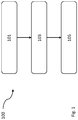
- the method 100 comprises a calibration step 101 for calibrating a gas sensor at a first calibration point in time with a defined concentration of test gas, a first calibration result being determined during the calibration, and at least one gas supply measured value determined at a point in time preceding the first calibration point being determined, a determination step 103 for determining a gas supply reference value by placing the at least one gas supply measurement value in a mathematical relationship with the first calibration result and a further calibration result of the gas sensor, which was determined at a point in time preceding the first calibration point in time, and an adjustment step 105 for adjusting the gas supply system using the gas supply reference value .
- FIG. 2 a diagram 200 is shown.
- the diagram 200 extends on its abscissa 201 over time and on its ordinate 203 over a sensor sensitivity in ⁇ A / ppm.
- a gas sensor of a gas supply system is calibrated by, for example, an operator with a test gas cylinder that contains a defined concentration of target gas or test gas.
- test particles ejected from the test gas bottle migrate to the gas sensor so that the gas sensor measures a gas supply measured value with a sensor sensitivity of, for example, 1.5 ⁇ A / ppm, which corresponds to a first calibration result S1.
- a basic gas supply reference value G0 of, for example, 2000 ppm * s is set on the gas supply system, which was determined or specified at a point in time t0 before the first calibration point in time t1.
- a gas supply measured value (M1) which is determined at a point in time (t2) preceding the first calibration point in time (t1), corresponds, for example, to 1000 ppm * s.
- a new gas supply reference value G1 can be determined by means of the calculation rule (1), where S1 is a first calibration result, S0 is a further calibration result, M1 corresponds to a gas supply measurement and G1 corresponds to a gas supply reference value.
- M1 can be a mean value or median value of a number N of last gas generator signals before a first calibration process for determining the first calibration result S1.
- G 1 M. 1 ⁇ S. 0 / S. 1
- the method 100 can be used, for example, with raw sensor values, for example currents of an electrochemical sensor, or with already calculated concentration values of a sensor.
- a "continuous exposure" with gas can be carried out.
- a stable measured value is then awaited and the sensitivity is determined.
- an integral of a sensor response of the gas sensor to an application of a test gas a stroke of a sensor response of the gas sensor to an application of a test gas or a time until the peak of the sensor response of the gas sensor to an application of a test gas can be used.
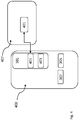
- the gas supply system 300 comprises an interface 301 to a gas sensor, a gas sensor 303, a gas supply 305 and a computing unit 307.
- the computing unit is configured to determine a first calibration result at a first calibration point in time for calibrating the gas sensor with a defined concentration of test gas.
- the computing unit 307 is configured to determine at least one gas supply measured value at a point in time preceding the first calibration point in time.
- the computing unit 307 is configured to determine a gas supply reference value by placing the at least one gas supply measured value in a mathematical relationship with the first calibration result and a further calibration result of the gas sensor determined at a point in time preceding the first calibration point in time.
- the computing unit 307 is configured to adjust the gas supply system 300 on the basis of the gas supply reference value.
- the gas sensor 303 is communicatively connected to the interface 301 via an electrical connection, such as, for example, a cable or a soldered connection. Accordingly, the gas sensor 303 transmits measured values via the interface 301 to the computing unit 307.
- an electrical connection such as, for example, a cable or a soldered connection.
- a gas supply system 400 is shown.
- the gas supply system 400 is similar to the gas supply system 300 according to FIG Fig. 3 with the exception that the interface 301 is connected to an external gas sensor 401 in, for example, a gas measuring device 407 via a wireless interface. Accordingly, the gas supply system 400 forms a portable module for testing various gas sensors.
- the interface 301 can have a first communication module 403 for wireless communication via, for example, WLAN, Bluetooth, nearfield communication, Zigbee or a cellular signal, such as 5G, and a second communication module 405 for connecting a cable, such as a COM port or include a USB port.
- a first communication module 403 for wireless communication via, for example, WLAN, Bluetooth, nearfield communication, Zigbee or a cellular signal, such as 5G
- a second communication module 405 for connecting a cable, such as a COM port or include a USB port.
- the gas supply system 400 can include an output unit 409, such as an LED, a loudspeaker and / or a display, in order to output warning messages, such as, for example, an indication to replace the gas sensor 401.
- an output unit 409 such as an LED, a loudspeaker and / or a display, in order to output warning messages, such as, for example, an indication to replace the gas sensor 401.
Landscapes
- Engineering & Computer Science (AREA)
- Chemical & Material Sciences (AREA)
- Physics & Mathematics (AREA)
- General Physics & Mathematics (AREA)
- Life Sciences & Earth Sciences (AREA)
- Health & Medical Sciences (AREA)
- Theoretical Computer Science (AREA)
- Medicinal Chemistry (AREA)
- Combustion & Propulsion (AREA)
- Pathology (AREA)
- Immunology (AREA)
- General Health & Medical Sciences (AREA)
- Biochemistry (AREA)
- Analytical Chemistry (AREA)
- Food Science & Technology (AREA)
- Mathematical Optimization (AREA)
- Computational Mathematics (AREA)
- Pure & Applied Mathematics (AREA)
- Mathematical Analysis (AREA)
- Mathematical Physics (AREA)
- General Engineering & Computer Science (AREA)
- Data Mining & Analysis (AREA)
- Computing Systems (AREA)
- Software Systems (AREA)
- Databases & Information Systems (AREA)
- Algebra (AREA)
- Operations Research (AREA)
- Investigating Or Analyzing Materials By The Use Of Electric Means (AREA)
- Measuring Oxygen Concentration In Cells (AREA)
Abstract
einen Ermittlungsschritt zum Ermitteln (103) eines Gasversorgungsreferenzwerts (G1), indem der mindestens eine Gasversorgungsmesswert (M1) in eine mathematische Be-ziehung gesetzt wird mit dem ersten Kalibrierungsergebnis (S1) und einem Kalibrierungsergebnis (S0) des Gassensors (303, 401), das zu einem dem ersten Kalibrierungszeitpunkt (t1) vorangegangenen Zeitpunkt (t0) ermittelt wurde und einen Justierungsschritt zum Justieren (105) des Gasversorgungssystems anhand des Gasversorgungsreferenzwerts (G1).
Description
- Die Erfindung betrifft ein Verfahren zum Justieren eines Gasversorgungssystems und ein Gasversorgungssystem mit Justierfunktion
- Elektrochemische und katalytische Sensoren zur Überwachung von toxischen bzw. explosiven Gasen und Dämpfen sind vielfach in Gebrauch. Es ist bekannt, dass Sensoren, insbesondere elektrochemische Sensoren, im Laufe ihrer Lebenszeit ihre Messeigenschaften, insbesondere ihre Sensitivität, also ihre Empfindlichkeit und/oder ihre Ansprechzeit, bis ein Messwert 90 % einer wirklich anliegenden Gaskonzentration erreicht, verändern und daher regelmäßig überprüft, insbesondere kalibriert werden müssen.
- Eine Kalibration bzw. Kalibrierung erfolgt in der Regel in einem Zweischrittverfahren, bei dem in einem ersten Schritt ein Nullpunkt durch Beaufschlagung mit sogenanntem "Nullgas", also einem Gas, das keine Beimengungen enthält, bestimmt wird. In einem zweiten Schritt wird die Sensitivität eines jeweiligen Sensors durch Beaufschlagung mit einem Prüfgas, also einem Gas mit einer definierten Konzentration an Beimengungen, ermittelt.
- Zum Erzeugen eines Prüfgases, kann ein Gasgenerator genutzt werden, der das Prüfgas in regelmäßigen Abständen produziert, um einen jeweiligen Sensor bspw. automatisch zu überprüfen bzw. zu kalibrieren. Alternativ kann ein Prüfgas mit einer Gasflasche bereitgestellt werden.
- Bei einer Kalibrierung ohne Gasgenerator muss ein Betreiber bzw. ein Nutzer, die Kalibrierung manuell vor Ort an einem jeweiligen Sensor mittels einer Gasflasche durchführen, was einerseits aufwändig, andererseits ggf. für den Betreiber in entsprechender Atmosphäre gefährlich sein kann.
- Um falsche Interpretationen von durch einen Sensor ermittelten Messwerten zu vermeiden, kann ein jeweiliges Messsystem justiert werden, indem ein Nullpunkt und eine Sensitivität des Sensors in Abhängigkeit einer während einer Überprüfung bzw. einer Kalibrierung erkannten Abweichung zwischen einem aktuellen Zustand und einem Referenzzustand des Sensors angepasst bzw. korrigiert wird.
- Wird ein Gasgenerator zur Kalibrierung bzw. Justierung eingesetzt, so unterliegt auch dieser einem Alterungsprozess und generiert über die Lebenszeit bei gleichem Stimulus immer weniger Gas, was von einem automatischen System zur Kalibrierung bzw. Justierung eines Sensors als Abfall eines Antwortverhaltens des Sensors interpretiert wird, sodass es zu Situationen kommen kann, in denen der Sensor unnötig getauscht bzw. falsch fehlerhaft gemeldet wird. Die Empfindlichkeit des Sensors wird entsprechend als zu geringgeschätzt.
- Vor dem voranstehend beschriebenen technischen Hintergrund hat der Erfindung die Aufgabe zugrunde gelegen, ein Gasversorgungssystem bereitzustellen, das die voranstehend beschriebenen Nachteile zumindest teilweise nicht aufweist. Insbesondere ist es eine Aufgabe der vorliegenden Erfindung, einen Zeitbereich zwischen zwei Kalibrierungsvorgängen zur Kalibrierung eines Sensors eines Gasmessgeräts zu maximieren.
- Voranstehende Aufgabe wird gelöst durch ein Verfahren und ein Gasversorgungssystem mit den Merkmalen der jeweiligen unabhängigen Ansprüche. Weitere Merkmale und Details der Erfindung ergeben sich aus den Unteransprüchen, der Beschreibung und den Zeichnungen. Dabei gelten Merkmale und Details, die im Zusammenhang mit dem erfindungsgemäßen Verfahren beschrieben sind, selbstverständlich auch im Zusammenhang mit dem erfindungsgemäßen Gasversorgungssystem und jeweils umgekehrt, sodass bezüglich der Offenbarung zu den einzelnen Erfindungsaspekten stets wechselseitig Bezug genommen wird beziehungsweise werden kann.
- Es wird somit ein Verfahren zum Justieren eines Gasversorgungssystems vorgestellt. Das Verfahren umfasst einen Kalibrierungsschritt zum Kalibrieren eines Gassensors zu einem ersten Kalibrierungszeitpunkt mit einer definierten Konzentration an Prüfgas, wobei während des Kalibrierens ein erstes Kalibrierungsergebnis ermittelt wird, und wobei mindestens ein zu einem dem ersten Kalibrierungszeitpunkt vorangegangenen Zeitpunkt ermittelter Gasversorgungsmesswert ermittelt wird, einen Ermittlungsschritt zum Ermitteln eines Gasversorgungsreferenzwerts, indem der mindestens eine Gasversorgungsmesswert in eine mathematische Beziehung gesetzt wird mit dem ersten Kalibrierungsergebnis und einem weiteren Kalibrierungsergebnis des Gassensors, das zu einem dem ersten Kalibrierungszeitpunkt vorangegangenen Zeitpunkt ermittelt wurde, und einen Justierungsschritt zum Justieren des Gasversorgungssystems anhand des Gasversorgungsreferenzwerts.
- Unter einer Kalibrierung bzw. einem Kalibrieren oder einer Kalibration ist im Kontext der vorgestellten Erfindung ein Vorgang zu verstehen, bei dem ein aktueller Zustand eines Gassensors und/oder einer Gasversorgung des vorgestellten Gasmessgeräts relativ zu einem Referenzzustand ermittelt wird.
- Unter einer Justierung bzw. einem Justieren ist im Kontext der vorgestellten Erfindung ein Vorgang zu verstehen, bei dem der Gassensor und/oder die Gasversorgung des vorgestellten Gasversorgungssystems in Abhängigkeit eines aktuell ermittelten Zustands des Gassensors und/oder der Gasversorgung angepasst bzw. kontrolliert, d.h. gesteuert oder geregelt werden. Insbesondere ist unter einer Justierung ein Vorgang zu verstehen, bei dem Ergebnisse einer Kalibrierung zur Korrektur des Gasversorgungssystems bzgl. einer Abweichung zwischen einem aktuellen Zustand und einem Referenzzustand verwendet werden. Beispielsweise kann bei einer Justierung ein jeweiliger Messwert bzw. ein Antwortverhalten eines jeweiligen Gassensors angepasst bzw. korrigiert werden.
- Unter einer Recheneinheit ist im Kontext der vorgestellten Erfindung eine programmierbare Prozessoreinheit bzw. Subprozessoreinheit zu verstehen. Eine Recheneinheit kann als Computer, insbesondere als verteiltes Rechensystem ausgestaltet sein und mit einem Speicher, wie bspw. einem Netzwerkspeicher oder einem Feststoffspeicher in kommunikativem Kontakt stehen. Insbesondere kann eine Recheneinheit ein Steuergerät, wie bspw. ein Microcontroller sein.
- Unter einer definierten Konzentration an Prüfgas ist im Kontext der vorgestellten Erfindung eine vorgegebene bzw. bekannte Konzentration an Prüfgas zu verstehen, die bspw. händisch bei einem Kalibrierungsvorgang aus einer Prüfgasflasche oder mittels eines Gasgenerators bereitgestellt wird. Dabei kann die definierte Konzentration an Prüfgas um einen Toleranzbetrag schwanken.
- Das vorgestellte Verfahren dient insbesondere zum Justieren einer Gasversorgung, insbesondere eines Gasgenerators, die zum Kalibrieren bzw. Justieren eines Sensors verwendet wird. Dazu ist vorgesehen, dass eine Gasversorgung während einer Kalibrierung bzw. Justierung eines jeweiligen Sensors mit justiert wird.
- Durch eine justierte Gasversorgung kann eine fehlerhafte Prüfung eines Sensors, bspw. bedingt durch eine falsche Ansteuerung der Gasversorgung, vermieden werden. Entsprechend kann ein Zeitbereich zwischen zwei Kalibrierungsvorgängen eines Sensors unabhängig von einem Alterungszustand der Gasversorgung gewählt und entsprechend maximiert werden.
- Das vorgestellte Verfahren basiert darauf, dass ein aktueller bzw. erster Kalibrierungsvorgang eines Sensors genutzt wird, um auf einen Alterungszustand einer Gasversorgung, die den Sensor mit Prüfgas beaufschlagt, zu schließen. Dazu wird während des ersten Kalibrierungsvorgangs, also zu einem ersten Kalibrierungszeitpunkt, ein erstes Kalibrierungsergebnis des Sensors, also eine Sensitivität des Sensors durch eine Beaufschlagung mit Prüfgas, ermittelt.
- Zusätzlich zu dem ersten Kalibrierungsergebnis wird mindestens ein Gasversorgungsmesswert zu einem Zeitpunkt ermittelt, der zeitlich vor, insbesondere zeitlich unmittelbar vor, dem ersten Kalibrierungszeitpunkt durch den Sensor erfasst wurde. In Verbindung mit einem weiteren Kalibrierungsergebnis, das bspw. vor dem ersten Kalibrierungszeitpunkt ermittelt wurde, kann anhand des Gasversorgungsmesswerts und des ersten Kalibrierungsergebnisses ein Gasversorgungsreferenzwert ermittelt werden. Dies bedeutet, dass eine Veränderung der Sensitivität des Sensors zwischen zwei Kalibrierungsvorgängen mathematisch in Beziehung gesetzt wird mit einem vor dem ersten Kalibrierungsvorgang ermittelten Gasversorgungsmesswert, insbesondere einem letzten Gasversorgungsmesswert vor dem ersten Kalibrierungsvorgang, um den Gasversorgungsreferenzwert zu ermitteln.
- Sobald der Gasversorgungsreferenzwert bekannt ist, kann dieser dazu verwendet werden, eine entsprechende Gasversorgung zu justieren, d.h. so einzustellen, dass eine Menge an durch die Gasversorgung zu erzeugendem Prüfgas bzw. eine Aktivierungszeit der Gasversorgung unter Verwendung des Gasversorgungsreferenzwerts ermittelt wird.
- Zum Ermitteln des Gasversorgungsmesswerts kann vorgesehen sein, dass ein jeweiliger Sensor regelmäßig, insbesondere zwischen jeweiligen Kalibrierungsvorgängen mit einem Prüfgas beaufschlagt wird.
- Durch ein mathematisches in Beziehung setzen einer Veränderung einer Sensitivität des Sensors bzw. einer Alterung des Sensors mit einem Gasversorgungsmesswert kann der quantitative Anteil einer Abweichung des Gasversorgungsmesswerts zu einem Sollwert, der durch die Alterung der Gasversorgung bedingt ist, ermittelt werden. Der quantitative Anteil der Abweichung des Gasversorgungsmesswerts zu dem Sollwert, der durch die Alterung der Gasversorgung bedingt ist kann, sobald dieser bekannt ist, zur Justierung der Gasversorgung verwendet werden, sodass dieser Anteil ausgeglichen oder bei weiteren Kalibrierungsvorgängen berücksichtigt wird.
- Weiterhin kann anhand des quantitativen Anteils der Abweichung des Gasversorgungsmesswerts zu einem Sollwert, d.h. der Alterung der Gasversorgung, ein Kriterium bestimmt werden, wann die Gasversorgung ausgewechselt werden muss, weil seine generierte Gasmenge und ein entsprechendes Signal-zu-Rauschverhältnis zu gering sind.
- Insbesondere kann mittels des vorgestellten Verfahrens nach einer Justierung eines Gassensors eine Alterung des Gassensors, d.h. ein auf physikalische Eigenschaften des Gassensors begründeter Abfall von Messwerten seit einer vorherigen Kalibrierung bzw. Justierung des Gassensors bestimmt werden. Diese Alterung des Gassensors kann mit einem Ergebnis eines Sensitivitätsabfalls einer Gasversorgung verglichen werden. Dabei entspricht die relative Alterung des Gasgenerators einem Verhältnis eines aktuell ermittelten Referenzwerts und eines alten bzw. vor dem aktuell ermittelten Referenzwert gültigen Referenzwerts. Entsprechend ist der Gasgenerator nicht gealtert, wenn zu verschiedenen Zeitpunkten ermittelte Referenzwerte konstant bzw. gleich sind.
- Das erfindungsgemäß vorgesehene mathematische in Beziehung setzen kann ein Ermitteln einer Abfallcharakteristik, wie bspw. einer Steigung einer Anzahl von Gasversorgungsmesswerten umfassen. Entsprechend kann eine ermittelte Abfallcharakteristik bei dem erfindungsgemäßen Justiervorgang korrigiert werden, indem das Gasversorgungssystem zum Ausgleichen der Abfallcharakteristik konfiguriert wird. Dazu kann bspw. ein entsprechender Gasversorgungsreferenzwert an dem Gasversorgungssystem eingestellt und/oder ein Antwortverhalten eines jeweiligen Gassensors angepasst bzw. korrigiert werden.
- Es kann vorgesehen sein, dass das Kalibrieren des Gassensors und das Ermitteln des Gasversorgungsreferenzwerts zu einem gegenüber dem ersten Kalibrierungszeitpunkt späteren Zeitpunkt wiederholt werden, wobei dann das erste Kalibrierungsergebnis als weiteres Kalibrierungsergebnis verwendet wird, ein zu dem späteren Zeitpunkt ermitteltes Kalibrierungsergebnis als erstes Kalibrierungsergebnis verwendet wird und mindestens ein zu einem vor dem späteren Zeitpunkt liegenden Zeitpunkt ermittelter Gasversorgungsmesswert als mindestens einer Gasversorgungsmesswert verwendet wird.
- Durch eine wiederholte Ausführung jeweiliger Teilschritte des vorgestellten Verfahrens kann ein Alterungsprozess einer jeweiligen Gasversorgung kontinuierlich überwacht und entsprechend korrigiert werden. Daher kann ein Einfluss des Alterungsprozesses der Gasversorgung auf einen Kalibrierungsvorgang minimiert und ein jeweiliger Sensor unabhängig von einem Alterungszustand der Gasversorgung justiert werden.
- Es kann weiterhin vorgesehen sein, dass der Gasversorgungsreferenzwert ermittelt wird, indem der mindestens eine Gasversorgungsmesswert multipliziert wird mit einem Verhältnis des weiteren Kalibrierungsergebnisses und des ersten Kalibrierungsergebnisses.
- Die Rechenvorschrift (1) zum Ermitteln des Gasversorgungsreferenzwerts hat sich als besonders vorteilhaft erwiesen, wobei folgendes gilt: S1 entspricht einem ersten Kalibrierungsergebnis, S0 einem weiteren Kalibrierungsergebnis, M1 einem Gasversorgungsmesswert und G1 einem Gasversorgungsreferenzwert. Dabei kann M1 zum Beispiel ein Mittelwert bzw. Medianwert einer Anzahl N letzter Gasversorgungsmesswerte vor einem ersten Kalibrierungsvorgang zum Ermitteln des ersten Kalibrierungsergebnisses S1 sein.

- Es kann weiterhin vorgesehen sein, dass der mindestens eine Gasversorgungsmesswert (M1) durch einen der folgenden Ermittlungsschritte ermittelt wird:
- a) Ermitteln eines Integrals einer Sensorantwort des Gassensors (303, 401)
- b) Ermitteln einer Steigung einer Sensorantwort des Gassensors (303, 401),
- c) Ermitteln einer Ansprechzeit einer Sensorantwort des Gassensors (303, 401),
- d) Ermitteln eines Kurvenverlaufs einer Sensorantwort des Gassensors (303, 401).
- Insbesondere kann vorgesehen sein, dass eine Warnmeldung zum Auswechseln der Gasversorgung ausgegeben wird, wenn eine Differenz zwischen dem Gasversorgungsmesswert und dem Gasversorgungsreferenzwert sich von einem vorgegebenen Schwellenwert unterscheidet.
- Da eine Differenz zwischen dem Gasversorgungsmesswert und dem Gasversorgungsreferenzwert einen Alterungszustand der Gasversorgung angibt, kann die Differenz als Maß für eine Auswechslung der Gasversorgung verwendet werden. So kann, sollte bspw. die Differenz größer werden als ein vorgegebener Schwellenwert, davon ausgegangen werden, dass die Gasversorgung alt bzw. verschlissen ist und nichtmehr zum Kalibrieren eines Sensors geeignet ist.
- Es kann weiterhin vorgesehen sein, dass ein Wert der Konzentration an Prüfgas, die mittels der Gasversorgung bereitgestellt wird, auf den Gasversorgungsreferenzwert korrigiert wird, d.h. bspw. die Konzentration auf den Gasversorgungsreferenzwert aufsummiert wird, oder die Gasversorgung unter Verwendung des Gasversorgungsreferenzwerts derart gesteuert wird, dass die Konzentration an Prüfgas, die mittels der Gasversorgung bereitgestellt wird, einem vorgegebenen Sollwert entspricht.
- Mittels des erfindungsgemäß berechneten Gasversorgungsreferenzwerts kann eine Gasversorgung derart kontrolliert, d.h. gesteuert oder geregelt werden, dass altersbedingte Veränderungen der Gasversorgung ausgeglichen werden.
- Zum Justieren des erfindungsgemäß vorgesehenen Gasversorgungssystems kann eine erwartete Prüfgaskurvenform des Gasversorgungssystems kalibriert und justiert werden. Dabei kann bspw. für den Fall, wenn über eine Prüfgaskurvenform bspw. ein Verstopfungszustand eines Sensoreingangs festgestellt wird, die Prüfgaskurvenform über die Zeit jedoch ändert, bei einer Sensorkalibrierung auch diese Referenzkurvenform justiert werden.
- Weiterhin kann mittels des vorgestellten Verfahrens ein Gasversorgungssignal, bspw. ein sogenanntes "Time to Peak des Prüfgasimpulses" zum Bestimmen einer Ansprechzeit, bspw. einer sogenannten "T90-Zeit" eines jeweiligen Sensors kalibriert und/oder justiert werden.
- In einem zweiten Aspekt betrifft die vorgestellte Erfindung ein Gasversorgungssystem mit Justierungsfunktion. Das Gasversorgungssystem umfasst eine Schnittstelle zu einem Gassensor, eine Gasversorgung und eine Recheneinheit. Die Recheneinheit ist dazu konfiguriert, ein erstes Kalibrierungsergebnis zu einem ersten Kalibrierungszeitpunkt zum Kalibrieren des Gassensors mit einer definierten Konzentration an Prüfgas zu ermitteln und mindestens einen Gasversorgungsmesswert zu einem dem ersten Kalibrierungszeitpunkt vorangegangenen Zeitpunkt zu ermitteln. Weiterhin ist die Recheneinheit dazu konfiguriert, einen Gasversorgungsreferenzwert zu ermitteln, indem der mindestens eine Gasversorgungsmesswert in eine mathematische Beziehung gesetzt wird mit dem ersten Kalibrierungsergebnis und einem zu einem dem ersten Zeitpunkt vorangegangenen Zeitpunkt ermittelten weiteren Kalibrierungsergebnis des Gassensors, und das Gasversorgungssystems anhand des Gasversorgungsreferenzwerts zu justieren.
- Das vorgestellte Verfahren dient insbesondere zum Betrieb des vorgestellten Gasversorgungssystems.
- Das vorgestellte Gasversorgungssystem umfasst eine Schnittstelle zu einem Gassensor, sodass die Recheneinheit des Gasversorgungssystems mit dem Gassensor in kommunikativem Kontakt steht und bspw. durch den Gassensor ermittelte Messwerte empfangen kann. Dabei kann die Schnittstelle drahtgebunden oder drahtlos ausgestaltet sein. Entsprechend kann der Gassensor als integraler Bestandteil des Gasversorgungssystems ausgestaltet sein oder als externes Modul lediglich über die Schnittstelle mit dem Gasversorgungssystem verbunden sein. Dies bedeutet, dass das Gasversorgungssystem dazu konfiguriert sein kann, sich selbst zu justieren oder einen externen Gassensor zu justieren.
- Das Gasversorgungssystem kann eine Gasflasche mit einem steuerbaren bzw. regelbaren Ventil zum Ablassen von Prüfgas oder einen Gasgenerator zum Erzeugen von Prüfgas umfassen.
- Weitere, die Erfindung verbessernde Maßnahmen ergeben sich aus der nachfolgenden Beschreibung zu einigen Ausführungsbeispielen der Erfindung, welche in den Figuren dargestellt sind. Sämtliche aus den Ansprüchen, der Beschreibung oder der Zeichnung hervorgehende Merkmale und/oder Vorteile, einschließlich konstruktiver Einzelheiten und räumlicher Anordnungen können sowohl für sich, als auch in den verschiedenen Kombinationen erfindungswesentlich sein. Es zeigen jeweils schematisch:
- Figur 1
- einen schematischen Ablauf einer möglichen Ausgestaltung des vorgestellten Verfahrens,
- Figur 2
- ein Diagramm mit Messwerten zur Durchführung des vorgestellten Verfahrens,
- Figur 3
- eine mögliche Ausgestaltung des vorgestellten Gasversorgungssystems mit einem integralen Gassensor,
- Figur 4
- eine mögliche Ausgestaltung des vorgestellten Gasversorgungssystems mit einem externen Gassensor.
- Elemente mit gleicher Funktion und Wirkungsweise sind in den
Fig. 1 bis 3 jeweils mit denselben Bezugszeichen versehen. - In
Fig. 1 ist ein Verfahren 100 dargestellt. Das Verfahren 100 umfasst einen Kalibrierungsschritt 101 zum Kalibrieren eines Gassensors zu einem ersten Kalibrierungszeitpunkt mit einer definierten Konzentration an Prüfgas, wobei während des Kalibrierens ein erstes Kalibrierungsergebnis ermittelt wird, und wobei mindestens ein zu einem dem ersten Kalibrierungszeitpunkt vorangegangenen Zeitpunkt ermittelter Gasversorgungsmesswert ermittelt wird, einen Ermittlungsschritt 103 zum Ermitteln eines Gasversorgungsreferenzwerts, indem der mindestens eine Gasversorgungsmesswert in eine mathematische Beziehung gesetzt wird mit dem ersten Kalibrierungsergebnis und einem weiteren Kalibrierungsergebnis des Gassensors, das zu einem dem ersten Kalibrierungszeitpunkt vorangegangenen Zeitpunkt ermittelt wurde, und einen Justierungsschritt 105 zum Justieren des Gasversorgungssystems anhand des Gasversorgungsreferenzwerts. - In
Fig. 2 ist ein Diagramm 200 dargestellt. Das Diagramm 200 erstreckt sich auf seiner Abszisse 201 über die Zeit und auf seiner Ordinate 203 über eine Sensorsensitivität in µA/ppm. - Zu einem ersten Kalibrierungszeitpunkt t1 wird ein Gassensor eines Gasversorgungssystems durch bspw. einen Betreiber mit einer Prüfgasflasche, die eine definierte Konzentration an Zielgas bzw. Prüfgas enthält, kalibriert.
- Die aus der Prüfgasflasche ausgestoßenen Prüfpartikel wandern zu dem Gassensor, sodass der Gassensor einen Gasversorgungsmesswert mit einer Sensorempfindlichkeit von bspw. 1,5 µA/ppm misst, die einem ersten Kalibrierungsergebnis S1 entspricht.
- Während des ersten Kalibrierungszeitpunkts t1 ist an dem Gasversorgungssystem ein Grundgasversorgungsreferenzwert G0 von bspw. 2000 ppm*s eingestellt, der zu einem Zeitpunkt t0 vor dem ersten Kalibrierungszeitpunkt t1 ermittelt bzw. vorgegebenen wurde. Über die Nutzungszeit des Gassensors und des Gasgenerators ergeben sich abfallende Gasgeneratorsignale 205, sodass ein Gasversorgungsmesswert (M1), der zu einem dem ersten Kalibrierungszeitpunkt (t1) vorangegangenen Zeitpunkt (t2) ermittelt wird, bspw. 1000 ppm*s entspricht.
- Ausgehend von dem Gasversorgungsmesswert (M1) würde das Gasversorgungssystem dem Gassensor eine Sensitivität von M1/GO = 1 µA /ppm zuordnen, da der Abfall der Gasgeneratorsignale 205 vollständig dem Gassensor zugeordnet würde.
- Tatsächlich ist aber auch der Gasgenerator gealtert, sodass eine Betreiberkalibrierung zum ersten Kalibrierungszeitpunkt t1 eine "wahre" Sensorsensitivitat von S1 = 1,5 µA/ppm ergibt.
- Dies bedeutet, dass der Gassensor und der Gasgenerator im gleichen Verhältnis gealtert sind. Ausgehend von dieser Erkenntnis kann ein neuer Gasversorgungsreferenzwert G1 mittels der Berechnungsvorschrift (1) ermittelt werden, wobei S1 einem ersten Kalibrierungsergebnis, S0 einem weiteren Kalibrierungsergebnis, M1 einem Gasversorgungsmesswert und G1 einem Gasversorgungsreferenzwert entspricht. Dabei kann M1 ein Mittelwert bzw. Medianwert einer Anzahl N letzter Gasgeneratorsignale vor einem ersten Kalibrierungsvorgang zum Ermitteln des ersten Kalibrierungsergebnisses S1 sein.

- Das Verfahren 100 kann bspw. mit Sensorrohwerten, von bspw. Strömen eines elektrochemischen Sensors oder mit bereits berechneten Konzentrationswerten eines Sensors genutzt werden.
- Zur Bestimmung der Sensitivität des Gassensors während einer Kalibrierung kann eine "Dauerbeaufschlagung" mit Gas durchgeführt werden. Anschließend wird ein stabiler Messwert abgewartet und die Sensitivität bestimmt. Dazu kann bspw. ein Integral einer Sensorantwort des Gassensors auf eine Beaufschlagung mit einem Prüfgas, ein Hub einer Sensorantwort des Gassensors auf eine Beaufschlagung mit einem Prüfgas oder eine Zeit bis zum Peak der Sensorantwort des Gassensors auf eine Beaufschlagung mit einem Prüfgas verwendet werden.
- In
Fig. 3 ist ein Gasversorgungssystem 300 dargestellt. Das Gasversorgungssystem 300 umfasst eine Schnittstelle 301 zu einem Gassensor, einen Gassensor 303, eine Gasversorgung 305 und eine Recheneinheit 307. Die Recheneinheit ist dazu konfiguriert ein erstes Kalibrierungsergebnis zu einem ersten Kalibrierungszeitpunkt zum Kalibrieren des Gassensors mit einer definierten Konzentration an Prüfgas zu ermitteln. - Weiterhin ist die Recheneinheit 307 dazu konfiguriert, mindestens einen Gasversorgungsmesswert, zu einem dem ersten Kalibrierungszeitpunkt vorangegangenen Zeitpunkt zu ermitteln.
- Weiterhin ist die Recheneinheit 307 dazu konfiguriert, einen Gasversorgungsreferenzwerts zu ermitteln, indem der mindestens eine Gasversorgungsmesswert in eine mathematische Beziehung gesetzt wird mit dem ersten Kalibrierungsergebnis und einem zu einem dem ersten Kalibrierungszeitpunkt vorangegangenen Zeitpunkt ermittelten weiteren Kalibrierungsergebnis des Gassensors.
- Weiterhin ist die Recheneinheit 307 dazu konfiguriert, das Gasversorgungssystem 300 anhand des Gasversorgungsreferenzwerts zu justieren.
- In dem in
Fig. 3 gezeigten Beispiel ist der Gassensor 303 über eine elektrische Verbindung, wie bspw. ein Kabel oder eine Lötverbindung mit der Schnittstelle 301 kommunikativ verbunden. Entsprechend übermittelt der Gassensor 303 Messwerte über die Schnittstelle 301 and die Recheneinheit 307. - In
Fig. 4 ist ein Gasversorgungssystem 400 dargestellt. Das Gasversorgungssystem 400 gleicht dem Gasversorgungssystem 300 gemäßFig. 3 mit der Ausnahme, dass die Schnittstelle 301 über eine Drahtlosschnittstelle mit einem externen Gassensor 401 in bspw. einem Gasmessgerät 407 verbunden ist. Entsprechend bildet das Gasversorgungssystem 400 ein portables Modul zum Testen verschiedener Gassensoren. - Dabei kann die Schnittstelle 301 ein erstes Kommunikationsmodul 403 zur drahtlosen Kommunikation über bspw. WLAN, Bluetooth, Nearfield Communication, Zigbee oder ein Mobilfunksignal, wie bspw. 5G, und ein zweites Kommunikationsmodul 405 zum Anschluss eines Kabels, wie bspw. einen COM-Port oder einen USB-Port umfassen.
- Optional kann das Gasversorgungssystem 400 eine Ausgabeeinheit 409, wie bspw. eine LED, einen Lautsprecher und/oder ein Display umfassen, um Warnmeldungen, wie bspw. einen Hinweis zum Austauschen des Gassensors 401 ausgegeben werden.
-
- 100
- Verfahren
- 101
- Kalibrierungsschritt
- 103
- Ermittlungsschritt
- 105
- Justierungsschritt
- 200
- Diagramm
- 201
- Abszisse
- 203
- Ordinate
- 205
- Gasgeneratorsignale
- t1
- erster Kalibrierungszeitpunkt
- S1
- erstes Kalibrierungsergebnis
- M1
- Gasversorgungsmesswert
- t2
- vorangegangener Zeitpunkt
- G0
- Gasversorgungsreferenzwert
- G1
- neuer Gasversorgungsreferenzwert
- 300
- Gasversorgungssystem
- 301
- Schnittstelle
- 303
- Gassensor
- 305
- Gasversorgung
- 307
- Recheneinheit
- 400
- Gasversorgungssystem
- 401
- externer Gassensor
- 403
- erstes Kommunikationsmodul
- 405
- zweites Kommunikationsmodul
- 407
- Gasmessgerät
- 409
- Ausgabeeinheit
Claims (10)
- Verfahren (100) zum Justieren eines Gasversorgungssystems (300, 400), wobei das Verfahren (100) die folgenden Schritte umfasst:- Kalibrieren (101) eines Gassensors (303, 401) zu einem ersten Kalibrierungszeitpunkt (t1) mit einer definierten Konzentration an Prüfgas, wobei während des Kalibrierens ein erstes Kalibrierungsergebnis (S1) ermittelt wird, und
wobei mindestens ein Gasversorgungsmesswert (M1) zu einem dem ersten Kalibrierungszeitpunkt (t1) vorangegangenen Zeitpunkt (t2) ermittelt wird,- Ermitteln (103) eines Gasversorgungsreferenzwerts (G1), indem der mindestens eine Gasversorgungsmesswert (M1) in eine mathematische Beziehung gesetzt wird mit dem ersten Kalibrierungsergebnis (S1) und einem Kalibrierungsergebnis (S0) des Gassensors (303, 401), das zu einem dem ersten Kalibrierungszeitpunkt (t1) vorangegangenen Zeitpunkt (t0) ermittelt wurde,- Justieren (105) des Gasversorgungssystems anhand des Gasversorgungsreferenzwerts (G1). - Verfahren (100) nach Anspruch 1,
dadurch gekennzeichnet, dass
das Kalibrieren des Gassensors (303, 401) und das Ermitteln des Gasversorgungsreferenzwerts zu einem gegenüber dem ersten Kalibrierungszeitpunkt (t1) späteren Zeitpunkt wiederholt werden, wobei dann das erste Kalibrierungsergebnis (S1) als weiteres Kalibrierungsergebnis verwendet wird, ein zu dem späteren Zeitpunkt ermitteltes Kalibrierungsergebnis als erstes Kalibrierungsergebnis verwendet wird und mindestens ein zu einem vor dem späteren Zeitpunkt liegenden Zeitpunkt ermittelter Gasversorgungsmesswert als mindestens einer Gasversorgungsmesswert (M1) verwendet wird. - Verfahren (100) nach Anspruch 1 oder 2,
dadurch gekennzeichnet, dass
der Gasversorgungsreferenzwert (G1) ermittelt wird, indem der mindestens eine Gasversorgungsmesswert (M1) multipliziert wird mit einem Verhältnis des weiteren Kalibrierungsergebnisses (S0) und des ersten Kalibrierungsergebnisses (S1). - Verfahren (100) nach einem der voranstehenden Ansprüche,
dadurch gekennzeichnet, dass der mindestens eine Gasversorgungsmesswert (M1) durch einen der folgenden Ermittlungsschritte ermittelt wird:- Ermitteln eines Integrals einer Sensorantwort des Gassensors (303, 401),- Ermitteln einer Steigung einer Sensorantwort des Gassensors (303, 401),- Ermitteln einer Ansprechzeit einer Sensorantwort des Gassensors (303, 401),- Ermitteln eines Kurvenverlaufs einer Sensorantwort des Gassensors (303, 401). - Verfahren (100) nach einem der vorangehenden Ansprüche,
dadurch gekennzeichnet, dass
in Abhängigkeit eines Abgleichs des Gasversorgungsreferenzwerts (G1) mit einem vorgegebenen Kriterium eine Warnmeldung ausgegeben wird. - Verfahren (1) nach Anspruch 5,
dadurch gekennzeichnet, dass
eine Warnmeldung zum Auswechseln einer Gasversorgung (305) des Gasversorgungssystems (300, 400) ausgegeben wird, wenn eine Differenz zwischen dem Gasversorgungsmesswert (M1) und dem Gasversorgungsreferenzwert (G1) sich von einem vorgegebenen Schwellenwert unterscheidet. - Verfahren (100) nach einem der vorangehenden Ansprüche,
dadurch gekennzeichnet, dass
ein Wert der Konzentration an Prüfgas, die mittels der Gasversorgung (305) bereitgestellt wird, auf den Gasversorgungsreferenzwert korrigiert wird oder die Gasversorgung (305) unter Verwendung des Gasversorgungsreferenzwerts derart gesteuert wird, dass die Konzentration an Prüfgas, die mittels der Gasversorgung (305) bereitgestellt wird, einem vorgegebenen Sollwert entspricht. - Gasversorgungssystem (300, 400) mit Justierungsfunktion,
wobei das Gasversorgungssystem (300, 400) umfasst:- eine Schnittstelle (301) zu einem Gassensor (303),- eine Gasversorgung (305),- eine Recheneinheit (307),wobei die Recheneinheit (307) dazu konfiguriert ist,
ein erstes Kalibrierungsergebnis (S1) zu einem ersten Kalibrierungszeitpunkt (t1) zum Kalibrieren eines mit der Schnittstelle verbundenen Gassensors (303) mit einer definierten Konzentration an Prüfgas zu ermitteln, mindestens einen Gasversorgungsmesswert (M1), zu einem dem ersten Kalibrierungszeitpunkt (t1) vorangegangenen Zeitpunkt (t2) zu ermitteln, und einen Gasversorgungsreferenzwert (G1) zu ermitteln, indem der mindestens eine Gasversorgungsmesswert (M1) in eine mathematische Beziehung gesetzt wird mit dem ersten Kalibrierungsergebnis (S1) und einem zu einem dem ersten Kalibrierungszeitpunkt (t1) vorangegangenen Zeitpunkt (t0) ermittelten weiteren Kalibrierungsergebnis (S0) des Gassensors (303), und
das Gasversorgungssystem (300, 400) anhand des Gasversorgungsreferenzwerts (G1) zu justieren. - Gasversorgungssystem (300, 400) nach Anspruch 8,
dadurch gekennzeichnet, dass
die Recheneinheit (307) zur Durchführung eines Verfahrens (100) nach einem der Ansprüche 2 bis 7 konfiguriert ist. - Gasversorgungssystem (300, 400) nach einem der vorangehenden Ansprüche, dadurch gekennzeichnet, dass
die Gasversorgung (305) einen Gasgenerator oder eine Gasflasche aufweist.
Applications Claiming Priority (1)
| Application Number | Priority Date | Filing Date | Title |
|---|---|---|---|
| DE102020001756.8A DE102020001756A1 (de) | 2020-03-17 | 2020-03-17 | Verfahren zum Justieren eines Gasversorgungssystems und Gasversorgungssystem mit Justierfunktion |
Publications (2)
| Publication Number | Publication Date |
|---|---|
| EP3882625A1 true EP3882625A1 (de) | 2021-09-22 |
| EP3882625B1 EP3882625B1 (de) | 2024-02-07 |
Family
ID=74856735
Family Applications (1)
| Application Number | Title | Priority Date | Filing Date |
|---|---|---|---|
| EP21160418.6A Active EP3882625B1 (de) | 2020-03-17 | 2021-03-03 | Verfahren zum justieren eines gasversorgungssystems und gasversorgungssystem mit justierfunktion |
Country Status (4)
| Country | Link |
|---|---|
| US (1) | US20210293766A1 (de) |
| EP (1) | EP3882625B1 (de) |
| CN (1) | CN113406268B (de) |
| DE (1) | DE102020001756A1 (de) |
Families Citing this family (1)
| Publication number | Priority date | Publication date | Assignee | Title |
|---|---|---|---|---|
| JP2024107990A (ja) * | 2023-01-30 | 2024-08-09 | 株式会社日立製作所 | 計測システム、計測方法およびコンピュータプログラム |
Citations (5)
| Publication number | Priority date | Publication date | Assignee | Title |
|---|---|---|---|---|
| DE4339472A1 (de) * | 1993-11-19 | 1995-07-13 | Draegerwerk Ag | Prüfgasgenerator zur Kalibrierung von Gasmeßgeräten |
| US20110108418A1 (en) * | 2009-11-12 | 2011-05-12 | Drager Safety Ag & Co. Kgaa | Gas sensor with test gas generator |
| US20110265550A1 (en) * | 2009-01-05 | 2011-11-03 | Synthesechemie Dr. Penth Gmbh | Measuring instrument and method for detecting the content of oil, hydrocarbons and oxidizable gases in air or compressed air |
| DE102015012440A1 (de) * | 2015-09-28 | 2017-03-30 | Dräger Safety AG & Co. KGaA | Elektrochemischer Gasgenerator für Ammoniak unter Verwendung lonischer Flüssigkeiten und Verwendung des Gasgenerators |
| CN109580887A (zh) * | 2019-01-24 | 2019-04-05 | 北京雪迪龙科技股份有限公司 | 具有零气发生装置自诊断功能的气体监测系统和监测方法 |
Family Cites Families (15)
| Publication number | Priority date | Publication date | Assignee | Title |
|---|---|---|---|---|
| US4314344A (en) * | 1980-01-31 | 1982-02-02 | Dasibi Environmental Corporation | Method and apparatus for generating selected gas concentrations |
| US6244093B1 (en) * | 1997-03-14 | 2001-06-12 | Kaushik K. Parekh | Method and apparatus for calibrating an air monitor using a flow matching valve |
| US20040055359A1 (en) | 2001-06-28 | 2004-03-25 | Rel-Tek | Automatic gas sensor calibration system |
| US6948352B2 (en) * | 2002-02-07 | 2005-09-27 | Walter Kidde Portable Equipment, Inc. | Self-calibrating carbon monoxide detector and method |
| US6997347B2 (en) * | 2003-07-02 | 2006-02-14 | Industrial Scientific Corporation | Apparatus and method for generating calibration gas |
| GB2457660A (en) * | 2008-02-19 | 2009-08-26 | Sphere Medical Ltd | Methods of calibrating a sensor in a patient monitoring system |
| EP2639583A1 (de) | 2012-03-12 | 2013-09-18 | Mettler-Toledo AG | Funktionsüberprüfung von Wärmeleitfähigkeits-Gassensoren |
| EP4218571B1 (de) * | 2012-03-16 | 2025-07-30 | Dexcom, Inc. | Systeme und verfahren zur verarbeitung von analytsensordaten |
| US10274349B2 (en) * | 2014-05-19 | 2019-04-30 | Medtronic Minimed, Inc. | Calibration factor adjustments for infusion devices and related methods and systems |
| DE102015015150B4 (de) | 2015-11-25 | 2022-05-12 | Dräger Safety AG & Co. KGaA | Gasmesssystem mit einer Gasmessvorrichtung und einer Kontrolleinrichtung und Verfahren zum Betrieb einer Gasmessvorrichtung mittels einer Kontrolleinrichtung |
| DE102016003284B4 (de) * | 2016-03-18 | 2022-05-19 | Dräger Safety AG & Co. KGaA | Gasmessvorrichtung mit einer Prüfvorrichtung zur Überprüfung eines Gassensors |
| KR101797637B1 (ko) | 2016-03-28 | 2017-11-20 | 주식회사아이센랩 | 교정장치 및 이를 구비한 가스성분 분석장치 |
| EP3203229B1 (de) * | 2017-04-06 | 2020-03-18 | Sensirion AG | Kalibrierung eines gassensors |
| DE102017004727A1 (de) | 2017-05-17 | 2018-11-22 | Drägerwerk AG & Co. KGaA | Verfahren zur Kalibrierung eines Gassensors |
| CN110501466B (zh) * | 2019-09-18 | 2022-04-29 | 天津市生态环境监测中心 | 一种臭氧开度测试系统及方法 |
-
2020
- 2020-03-17 DE DE102020001756.8A patent/DE102020001756A1/de not_active Withdrawn
-
2021
- 2021-03-03 EP EP21160418.6A patent/EP3882625B1/de active Active
- 2021-03-16 US US17/203,142 patent/US20210293766A1/en not_active Abandoned
- 2021-03-16 CN CN202110282630.2A patent/CN113406268B/zh active Active
Patent Citations (5)
| Publication number | Priority date | Publication date | Assignee | Title |
|---|---|---|---|---|
| DE4339472A1 (de) * | 1993-11-19 | 1995-07-13 | Draegerwerk Ag | Prüfgasgenerator zur Kalibrierung von Gasmeßgeräten |
| US20110265550A1 (en) * | 2009-01-05 | 2011-11-03 | Synthesechemie Dr. Penth Gmbh | Measuring instrument and method for detecting the content of oil, hydrocarbons and oxidizable gases in air or compressed air |
| US20110108418A1 (en) * | 2009-11-12 | 2011-05-12 | Drager Safety Ag & Co. Kgaa | Gas sensor with test gas generator |
| DE102015012440A1 (de) * | 2015-09-28 | 2017-03-30 | Dräger Safety AG & Co. KGaA | Elektrochemischer Gasgenerator für Ammoniak unter Verwendung lonischer Flüssigkeiten und Verwendung des Gasgenerators |
| CN109580887A (zh) * | 2019-01-24 | 2019-04-05 | 北京雪迪龙科技股份有限公司 | 具有零气发生装置自诊断功能的气体监测系统和监测方法 |
Also Published As
| Publication number | Publication date |
|---|---|
| CN113406268A (zh) | 2021-09-17 |
| DE102020001756A1 (de) | 2021-09-23 |
| EP3882625B1 (de) | 2024-02-07 |
| CN113406268B (zh) | 2023-11-24 |
| US20210293766A1 (en) | 2021-09-23 |
Similar Documents
| Publication | Publication Date | Title |
|---|---|---|
| EP0373422B1 (de) | Anordnung zum Überwachen der Güte von elektrischen Schweissungen | |
| DE69504727T2 (de) | Steuerverfahren vom Wiederstandschweissen mit unscharften Logik | |
| WO2020052970A1 (de) | Verfahren zur bestimmung einer kapazität einer batteriezelle, auswerteeinrichtung, überwachungsvorrichtung, hochvoltbatterie sowie kraftfahrzeug | |
| DE102016202500A1 (de) | Batteriesensor, Verfahren zum Kalibrieren eines Messwiderstands und Verwendung | |
| DE102016107528A1 (de) | Verfahren und System zur Bewertung einer elektrochemischen Speichereinheit | |
| DE102014220079A1 (de) | Verfahren zur Kalibrierung eines Sensors eines Batteriemanagementsystems | |
| EP3449264B1 (de) | Verfahren zum bestimmen eines laststroms und batteriesensor | |
| DE102013222475A1 (de) | Verfahren zur messung elektrischer leitfähigkeit und dieses verwendendes messsystem für elektrische leitfähigkeit | |
| EP2553479B2 (de) | Verfahren zum überwachen von leitungen durch bestimmung des elektrischen widerstands | |
| DE102018108493A1 (de) | Sensorvorrichtung und Sensoreinheit | |
| EP3882625B1 (de) | Verfahren zum justieren eines gasversorgungssystems und gasversorgungssystem mit justierfunktion | |
| EP2318853B1 (de) | Verfahren zur berechnung des ladezustandes einer batterie | |
| DE102013104203B4 (de) | Verfahren und Vorrichtung zur Bestimmung einer Restbetriebsdauer eines Messaufnehmers | |
| EP2936169A1 (de) | Verfahren zum einrichten eines stromsensors | |
| DE102016202501B4 (de) | Verfahren zum Bestimmen eines Kalibrierstrompulses | |
| DE102012108739A1 (de) | Verfahren und Vorrichtung zur Bestimmung eines Zustands einer Messsonde | |
| WO2025228656A1 (de) | Verfahren zum bereitstellen von lebensdauerdaten | |
| DE102018115460B4 (de) | Sensoranordnung für die voltammetrie | |
| DE102019123163A1 (de) | Messvorrichtung und kalibrierungsverfahren | |
| DE102009029073B4 (de) | Verfahren zur Durchführung eines Selbsttests für eine mikromechanische Sensorvorrichtung und entsprechende mikromechanische Sensorvorrichtung | |
| EP3588074A3 (de) | Verfahren zur reinigung, konditionierung, kalibration und/oder justage eines amperometrischen sensors | |
| DE102009050273B4 (de) | Verfahren zum Bestimmen der Kapazität einer Batterie | |
| AT527749B1 (de) | Ermitteln eines Isolationswiderstands | |
| DE102015210725B4 (de) | Elektrochemische pH-Messvorrichtung und Verfahren zu deren Evaluierung | |
| DE102013212288A1 (de) | Verfahren zum Betrieb eines Sensorelements und Sensorvorrichtung |
Legal Events
| Date | Code | Title | Description |
|---|---|---|---|
| PUAI | Public reference made under article 153(3) epc to a published international application that has entered the european phase |
Free format text: ORIGINAL CODE: 0009012 |
|
| STAA | Information on the status of an ep patent application or granted ep patent |
Free format text: STATUS: THE APPLICATION HAS BEEN PUBLISHED |
|
| AK | Designated contracting states |
Kind code of ref document: A1 Designated state(s): AL AT BE BG CH CY CZ DE DK EE ES FI FR GB GR HR HU IE IS IT LI LT LU LV MC MK MT NL NO PL PT RO RS SE SI SK SM TR |
|
| STAA | Information on the status of an ep patent application or granted ep patent |
Free format text: STATUS: REQUEST FOR EXAMINATION WAS MADE |
|
| 17P | Request for examination filed |
Effective date: 20220314 |
|
| RBV | Designated contracting states (corrected) |
Designated state(s): AL AT BE BG CH CY CZ DE DK EE ES FI FR GB GR HR HU IE IS IT LI LT LU LV MC MK MT NL NO PL PT RO RS SE SI SK SM TR |
|
| GRAP | Despatch of communication of intention to grant a patent |
Free format text: ORIGINAL CODE: EPIDOSNIGR1 |
|
| STAA | Information on the status of an ep patent application or granted ep patent |
Free format text: STATUS: GRANT OF PATENT IS INTENDED |
|
| INTG | Intention to grant announced |
Effective date: 20231004 |
|
| GRAJ | Information related to disapproval of communication of intention to grant by the applicant or resumption of examination proceedings by the epo deleted |
Free format text: ORIGINAL CODE: EPIDOSDIGR1 |
|
| STAA | Information on the status of an ep patent application or granted ep patent |
Free format text: STATUS: REQUEST FOR EXAMINATION WAS MADE |
|
| GRAP | Despatch of communication of intention to grant a patent |
Free format text: ORIGINAL CODE: EPIDOSNIGR1 |
|
| STAA | Information on the status of an ep patent application or granted ep patent |
Free format text: STATUS: GRANT OF PATENT IS INTENDED |
|
| GRAS | Grant fee paid |
Free format text: ORIGINAL CODE: EPIDOSNIGR3 |
|
| INTC | Intention to grant announced (deleted) | ||
| GRAA | (expected) grant |
Free format text: ORIGINAL CODE: 0009210 |
|
| STAA | Information on the status of an ep patent application or granted ep patent |
Free format text: STATUS: THE PATENT HAS BEEN GRANTED |
|
| INTG | Intention to grant announced |
Effective date: 20231211 |
|
| AK | Designated contracting states |
Kind code of ref document: B1 Designated state(s): AL AT BE BG CH CY CZ DE DK EE ES FI FR GB GR HR HU IE IS IT LI LT LU LV MC MK MT NL NO PL PT RO RS SE SI SK SM TR |
|
| REG | Reference to a national code |
Ref country code: GB Ref legal event code: FG4D Free format text: NOT ENGLISH |
|
| REG | Reference to a national code |
Ref country code: CH Ref legal event code: EP |
|
| REG | Reference to a national code |
Ref country code: IE Ref legal event code: FG4D Free format text: LANGUAGE OF EP DOCUMENT: GERMAN |
|
| REG | Reference to a national code |
Ref country code: DE Ref legal event code: R096 Ref document number: 502021002622 Country of ref document: DE |
|
| REG | Reference to a national code |
Ref country code: LT Ref legal event code: MG9D |
|
| REG | Reference to a national code |
Ref country code: NL Ref legal event code: FP |
|
| PG25 | Lapsed in a contracting state [announced via postgrant information from national office to epo] |
Ref country code: IS Free format text: LAPSE BECAUSE OF FAILURE TO SUBMIT A TRANSLATION OF THE DESCRIPTION OR TO PAY THE FEE WITHIN THE PRESCRIBED TIME-LIMIT Effective date: 20240607 |
|
| PG25 | Lapsed in a contracting state [announced via postgrant information from national office to epo] |
Ref country code: LT Free format text: LAPSE BECAUSE OF FAILURE TO SUBMIT A TRANSLATION OF THE DESCRIPTION OR TO PAY THE FEE WITHIN THE PRESCRIBED TIME-LIMIT Effective date: 20240207 |
|
| PG25 | Lapsed in a contracting state [announced via postgrant information from national office to epo] |
Ref country code: GR Free format text: LAPSE BECAUSE OF FAILURE TO SUBMIT A TRANSLATION OF THE DESCRIPTION OR TO PAY THE FEE WITHIN THE PRESCRIBED TIME-LIMIT Effective date: 20240508 |
|
| PG25 | Lapsed in a contracting state [announced via postgrant information from national office to epo] |
Ref country code: RS Free format text: LAPSE BECAUSE OF FAILURE TO SUBMIT A TRANSLATION OF THE DESCRIPTION OR TO PAY THE FEE WITHIN THE PRESCRIBED TIME-LIMIT Effective date: 20240507 Ref country code: HR Free format text: LAPSE BECAUSE OF FAILURE TO SUBMIT A TRANSLATION OF THE DESCRIPTION OR TO PAY THE FEE WITHIN THE PRESCRIBED TIME-LIMIT Effective date: 20240207 |
|
| PG25 | Lapsed in a contracting state [announced via postgrant information from national office to epo] |
Ref country code: ES Free format text: LAPSE BECAUSE OF FAILURE TO SUBMIT A TRANSLATION OF THE DESCRIPTION OR TO PAY THE FEE WITHIN THE PRESCRIBED TIME-LIMIT Effective date: 20240207 |
|
| PG25 | Lapsed in a contracting state [announced via postgrant information from national office to epo] |
Ref country code: RS Free format text: LAPSE BECAUSE OF FAILURE TO SUBMIT A TRANSLATION OF THE DESCRIPTION OR TO PAY THE FEE WITHIN THE PRESCRIBED TIME-LIMIT Effective date: 20240507 Ref country code: NO Free format text: LAPSE BECAUSE OF FAILURE TO SUBMIT A TRANSLATION OF THE DESCRIPTION OR TO PAY THE FEE WITHIN THE PRESCRIBED TIME-LIMIT Effective date: 20240507 Ref country code: LT Free format text: LAPSE BECAUSE OF FAILURE TO SUBMIT A TRANSLATION OF THE DESCRIPTION OR TO PAY THE FEE WITHIN THE PRESCRIBED TIME-LIMIT Effective date: 20240207 Ref country code: IS Free format text: LAPSE BECAUSE OF FAILURE TO SUBMIT A TRANSLATION OF THE DESCRIPTION OR TO PAY THE FEE WITHIN THE PRESCRIBED TIME-LIMIT Effective date: 20240607 Ref country code: HR Free format text: LAPSE BECAUSE OF FAILURE TO SUBMIT A TRANSLATION OF THE DESCRIPTION OR TO PAY THE FEE WITHIN THE PRESCRIBED TIME-LIMIT Effective date: 20240207 Ref country code: GR Free format text: LAPSE BECAUSE OF FAILURE TO SUBMIT A TRANSLATION OF THE DESCRIPTION OR TO PAY THE FEE WITHIN THE PRESCRIBED TIME-LIMIT Effective date: 20240508 Ref country code: FI Free format text: LAPSE BECAUSE OF FAILURE TO SUBMIT A TRANSLATION OF THE DESCRIPTION OR TO PAY THE FEE WITHIN THE PRESCRIBED TIME-LIMIT Effective date: 20240207 Ref country code: ES Free format text: LAPSE BECAUSE OF FAILURE TO SUBMIT A TRANSLATION OF THE DESCRIPTION OR TO PAY THE FEE WITHIN THE PRESCRIBED TIME-LIMIT Effective date: 20240207 Ref country code: BG Free format text: LAPSE BECAUSE OF FAILURE TO SUBMIT A TRANSLATION OF THE DESCRIPTION OR TO PAY THE FEE WITHIN THE PRESCRIBED TIME-LIMIT Effective date: 20240207 |
|
| PG25 | Lapsed in a contracting state [announced via postgrant information from national office to epo] |
Ref country code: PL Free format text: LAPSE BECAUSE OF FAILURE TO SUBMIT A TRANSLATION OF THE DESCRIPTION OR TO PAY THE FEE WITHIN THE PRESCRIBED TIME-LIMIT Effective date: 20240207 Ref country code: PT Free format text: LAPSE BECAUSE OF FAILURE TO SUBMIT A TRANSLATION OF THE DESCRIPTION OR TO PAY THE FEE WITHIN THE PRESCRIBED TIME-LIMIT Effective date: 20240607 |
|
| PG25 | Lapsed in a contracting state [announced via postgrant information from national office to epo] |
Ref country code: SE Free format text: LAPSE BECAUSE OF FAILURE TO SUBMIT A TRANSLATION OF THE DESCRIPTION OR TO PAY THE FEE WITHIN THE PRESCRIBED TIME-LIMIT Effective date: 20240207 Ref country code: PT Free format text: LAPSE BECAUSE OF FAILURE TO SUBMIT A TRANSLATION OF THE DESCRIPTION OR TO PAY THE FEE WITHIN THE PRESCRIBED TIME-LIMIT Effective date: 20240607 Ref country code: PL Free format text: LAPSE BECAUSE OF FAILURE TO SUBMIT A TRANSLATION OF THE DESCRIPTION OR TO PAY THE FEE WITHIN THE PRESCRIBED TIME-LIMIT Effective date: 20240207 Ref country code: LV Free format text: LAPSE BECAUSE OF FAILURE TO SUBMIT A TRANSLATION OF THE DESCRIPTION OR TO PAY THE FEE WITHIN THE PRESCRIBED TIME-LIMIT Effective date: 20240207 |
|
| PG25 | Lapsed in a contracting state [announced via postgrant information from national office to epo] |
Ref country code: DK Free format text: LAPSE BECAUSE OF FAILURE TO SUBMIT A TRANSLATION OF THE DESCRIPTION OR TO PAY THE FEE WITHIN THE PRESCRIBED TIME-LIMIT Effective date: 20240207 |
|
| PG25 | Lapsed in a contracting state [announced via postgrant information from national office to epo] |
Ref country code: SM Free format text: LAPSE BECAUSE OF FAILURE TO SUBMIT A TRANSLATION OF THE DESCRIPTION OR TO PAY THE FEE WITHIN THE PRESCRIBED TIME-LIMIT Effective date: 20240207 |
|
| PG25 | Lapsed in a contracting state [announced via postgrant information from national office to epo] |
Ref country code: CZ Free format text: LAPSE BECAUSE OF FAILURE TO SUBMIT A TRANSLATION OF THE DESCRIPTION OR TO PAY THE FEE WITHIN THE PRESCRIBED TIME-LIMIT Effective date: 20240207 Ref country code: EE Free format text: LAPSE BECAUSE OF FAILURE TO SUBMIT A TRANSLATION OF THE DESCRIPTION OR TO PAY THE FEE WITHIN THE PRESCRIBED TIME-LIMIT Effective date: 20240207 |
|
| PG25 | Lapsed in a contracting state [announced via postgrant information from national office to epo] |
Ref country code: SK Free format text: LAPSE BECAUSE OF FAILURE TO SUBMIT A TRANSLATION OF THE DESCRIPTION OR TO PAY THE FEE WITHIN THE PRESCRIBED TIME-LIMIT Effective date: 20240207 |
|
| PG25 | Lapsed in a contracting state [announced via postgrant information from national office to epo] |
Ref country code: SM Free format text: LAPSE BECAUSE OF FAILURE TO SUBMIT A TRANSLATION OF THE DESCRIPTION OR TO PAY THE FEE WITHIN THE PRESCRIBED TIME-LIMIT Effective date: 20240207 Ref country code: SK Free format text: LAPSE BECAUSE OF FAILURE TO SUBMIT A TRANSLATION OF THE DESCRIPTION OR TO PAY THE FEE WITHIN THE PRESCRIBED TIME-LIMIT Effective date: 20240207 Ref country code: RO Free format text: LAPSE BECAUSE OF FAILURE TO SUBMIT A TRANSLATION OF THE DESCRIPTION OR TO PAY THE FEE WITHIN THE PRESCRIBED TIME-LIMIT Effective date: 20240207 Ref country code: EE Free format text: LAPSE BECAUSE OF FAILURE TO SUBMIT A TRANSLATION OF THE DESCRIPTION OR TO PAY THE FEE WITHIN THE PRESCRIBED TIME-LIMIT Effective date: 20240207 Ref country code: DK Free format text: LAPSE BECAUSE OF FAILURE TO SUBMIT A TRANSLATION OF THE DESCRIPTION OR TO PAY THE FEE WITHIN THE PRESCRIBED TIME-LIMIT Effective date: 20240207 Ref country code: CZ Free format text: LAPSE BECAUSE OF FAILURE TO SUBMIT A TRANSLATION OF THE DESCRIPTION OR TO PAY THE FEE WITHIN THE PRESCRIBED TIME-LIMIT Effective date: 20240207 |
|
| REG | Reference to a national code |
Ref country code: CH Ref legal event code: PL |
|
| REG | Reference to a national code |
Ref country code: DE Ref legal event code: R097 Ref document number: 502021002622 Country of ref document: DE |
|
| PG25 | Lapsed in a contracting state [announced via postgrant information from national office to epo] |
Ref country code: LU Free format text: LAPSE BECAUSE OF NON-PAYMENT OF DUE FEES Effective date: 20240303 |
|
| PG25 | Lapsed in a contracting state [announced via postgrant information from national office to epo] |
Ref country code: MC Free format text: LAPSE BECAUSE OF FAILURE TO SUBMIT A TRANSLATION OF THE DESCRIPTION OR TO PAY THE FEE WITHIN THE PRESCRIBED TIME-LIMIT Effective date: 20240207 |
|
| PG25 | Lapsed in a contracting state [announced via postgrant information from national office to epo] |
Ref country code: MC Free format text: LAPSE BECAUSE OF FAILURE TO SUBMIT A TRANSLATION OF THE DESCRIPTION OR TO PAY THE FEE WITHIN THE PRESCRIBED TIME-LIMIT Effective date: 20240207 Ref country code: LU Free format text: LAPSE BECAUSE OF NON-PAYMENT OF DUE FEES Effective date: 20240303 |
|
| PG25 | Lapsed in a contracting state [announced via postgrant information from national office to epo] |
Ref country code: IT Free format text: LAPSE BECAUSE OF FAILURE TO SUBMIT A TRANSLATION OF THE DESCRIPTION OR TO PAY THE FEE WITHIN THE PRESCRIBED TIME-LIMIT Effective date: 20240207 |
|
| PLBE | No opposition filed within time limit |
Free format text: ORIGINAL CODE: 0009261 |
|
| STAA | Information on the status of an ep patent application or granted ep patent |
Free format text: STATUS: NO OPPOSITION FILED WITHIN TIME LIMIT |
|
| REG | Reference to a national code |
Ref country code: BE Ref legal event code: MM Effective date: 20240331 |
|
| PG25 | Lapsed in a contracting state [announced via postgrant information from national office to epo] |
Ref country code: IT Free format text: LAPSE BECAUSE OF FAILURE TO SUBMIT A TRANSLATION OF THE DESCRIPTION OR TO PAY THE FEE WITHIN THE PRESCRIBED TIME-LIMIT Effective date: 20240207 |
|
| 26N | No opposition filed |
Effective date: 20241108 |
|
| PG25 | Lapsed in a contracting state [announced via postgrant information from national office to epo] |
Ref country code: BE Free format text: LAPSE BECAUSE OF NON-PAYMENT OF DUE FEES Effective date: 20240331 |
|
| PG25 | Lapsed in a contracting state [announced via postgrant information from national office to epo] |
Ref country code: IE Free format text: LAPSE BECAUSE OF NON-PAYMENT OF DUE FEES Effective date: 20240303 |
|
| PG25 | Lapsed in a contracting state [announced via postgrant information from national office to epo] |
Ref country code: IE Free format text: LAPSE BECAUSE OF NON-PAYMENT OF DUE FEES Effective date: 20240303 Ref country code: BE Free format text: LAPSE BECAUSE OF NON-PAYMENT OF DUE FEES Effective date: 20240331 Ref country code: CH Free format text: LAPSE BECAUSE OF NON-PAYMENT OF DUE FEES Effective date: 20240331 |
|
| PG25 | Lapsed in a contracting state [announced via postgrant information from national office to epo] |
Ref country code: SI Free format text: LAPSE BECAUSE OF FAILURE TO SUBMIT A TRANSLATION OF THE DESCRIPTION OR TO PAY THE FEE WITHIN THE PRESCRIBED TIME-LIMIT Effective date: 20240207 |
|
| PGFP | Annual fee paid to national office [announced via postgrant information from national office to epo] |
Ref country code: AT Payment date: 20250417 Year of fee payment: 5 |
|
| PG25 | Lapsed in a contracting state [announced via postgrant information from national office to epo] |
Ref country code: CY Free format text: LAPSE BECAUSE OF FAILURE TO SUBMIT A TRANSLATION OF THE DESCRIPTION OR TO PAY THE FEE WITHIN THE PRESCRIBED TIME-LIMIT; INVALID AB INITIO Effective date: 20210303 |
|
| PG25 | Lapsed in a contracting state [announced via postgrant information from national office to epo] |
Ref country code: HU Free format text: LAPSE BECAUSE OF FAILURE TO SUBMIT A TRANSLATION OF THE DESCRIPTION OR TO PAY THE FEE WITHIN THE PRESCRIBED TIME-LIMIT; INVALID AB INITIO Effective date: 20210303 |
|
| PG25 | Lapsed in a contracting state [announced via postgrant information from national office to epo] |
Ref country code: TR Free format text: LAPSE BECAUSE OF FAILURE TO SUBMIT A TRANSLATION OF THE DESCRIPTION OR TO PAY THE FEE WITHIN THE PRESCRIBED TIME-LIMIT Effective date: 20240207 |
|
| PGFP | Annual fee paid to national office [announced via postgrant information from national office to epo] |
Ref country code: GB Payment date: 20260324 Year of fee payment: 6 |
|
| PGFP | Annual fee paid to national office [announced via postgrant information from national office to epo] |
Ref country code: DE Payment date: 20260320 Year of fee payment: 6 |
|
| PGFP | Annual fee paid to national office [announced via postgrant information from national office to epo] |
Ref country code: NL Payment date: 20260323 Year of fee payment: 6 |
|
| PGFP | Annual fee paid to national office [announced via postgrant information from national office to epo] |
Ref country code: FR Payment date: 20260324 Year of fee payment: 6 |