EP3881970A1 - Abrasive water-jet cutting machine - Google Patents
Abrasive water-jet cutting machine Download PDFInfo
- Publication number
- EP3881970A1 EP3881970A1 EP21161182.7A EP21161182A EP3881970A1 EP 3881970 A1 EP3881970 A1 EP 3881970A1 EP 21161182 A EP21161182 A EP 21161182A EP 3881970 A1 EP3881970 A1 EP 3881970A1
- Authority
- EP
- European Patent Office
- Prior art keywords
- abrasive
- water
- abrasive material
- mixing chamber
- tank
- Prior art date
- Legal status (The legal status is an assumption and is not a legal conclusion. Google has not performed a legal analysis and makes no representation as to the accuracy of the status listed.)
- Pending
Links
- 238000005520 cutting process Methods 0.000 title claims abstract description 121
- 239000003082 abrasive agent Substances 0.000 claims abstract description 127
- XLYOFNOQVPJJNP-UHFFFAOYSA-N water Substances O XLYOFNOQVPJJNP-UHFFFAOYSA-N 0.000 claims abstract description 100
- 239000000203 mixture Substances 0.000 claims abstract description 71
- 238000002156 mixing Methods 0.000 claims abstract description 64
- 239000012530 fluid Substances 0.000 claims abstract description 44
- 239000000725 suspension Substances 0.000 claims abstract description 13
- 230000002572 peristaltic effect Effects 0.000 claims abstract description 10
- 238000005086 pumping Methods 0.000 claims abstract description 10
- 238000000034 method Methods 0.000 claims description 20
- 230000010349 pulsation Effects 0.000 claims description 8
- 239000002861 polymer material Substances 0.000 claims 1
- 238000002347 injection Methods 0.000 description 18
- 239000007924 injection Substances 0.000 description 18
- 230000008569 process Effects 0.000 description 13
- 238000012360 testing method Methods 0.000 description 12
- 229910000963 austenitic stainless steel Inorganic materials 0.000 description 8
- 230000008901 benefit Effects 0.000 description 7
- 239000006185 dispersion Substances 0.000 description 7
- 239000000463 material Substances 0.000 description 7
- 230000005484 gravity Effects 0.000 description 6
- 230000000694 effects Effects 0.000 description 5
- 230000007613 environmental effect Effects 0.000 description 4
- 229920006395 saturated elastomer Polymers 0.000 description 4
- 239000000126 substance Substances 0.000 description 4
- 238000005553 drilling Methods 0.000 description 3
- 238000005516 engineering process Methods 0.000 description 3
- 239000007789 gas Substances 0.000 description 3
- 239000008187 granular material Substances 0.000 description 3
- 239000007788 liquid Substances 0.000 description 3
- 238000012545 processing Methods 0.000 description 3
- 238000011144 upstream manufacturing Methods 0.000 description 3
- 238000005054 agglomeration Methods 0.000 description 2
- 230000002776 aggregation Effects 0.000 description 2
- 230000015572 biosynthetic process Effects 0.000 description 2
- 230000008878 coupling Effects 0.000 description 2
- 238000010168 coupling process Methods 0.000 description 2
- 238000005859 coupling reaction Methods 0.000 description 2
- 230000007423 decrease Effects 0.000 description 2
- 239000002223 garnet Substances 0.000 description 2
- 230000006872 improvement Effects 0.000 description 2
- 238000007689 inspection Methods 0.000 description 2
- 230000010355 oscillation Effects 0.000 description 2
- 239000002245 particle Substances 0.000 description 2
- 230000002093 peripheral effect Effects 0.000 description 2
- 230000000750 progressive effect Effects 0.000 description 2
- 238000003860 storage Methods 0.000 description 2
- 208000019888 Circadian rhythm sleep disease Diseases 0.000 description 1
- 208000001456 Jet Lag Syndrome Diseases 0.000 description 1
- 230000001154 acute effect Effects 0.000 description 1
- 229910052833 almandine Inorganic materials 0.000 description 1
- 239000012620 biological material Substances 0.000 description 1
- 230000005540 biological transmission Effects 0.000 description 1
- 238000011088 calibration curve Methods 0.000 description 1
- 239000000919 ceramic Substances 0.000 description 1
- 238000012512 characterization method Methods 0.000 description 1
- 238000004891 communication Methods 0.000 description 1
- 239000012141 concentrate Substances 0.000 description 1
- 230000002596 correlated effect Effects 0.000 description 1
- 230000007547 defect Effects 0.000 description 1
- 230000001419 dependent effect Effects 0.000 description 1
- 238000013461 design Methods 0.000 description 1
- 239000012153 distilled water Substances 0.000 description 1
- 239000003349 gelling agent Substances 0.000 description 1
- 229910052500 inorganic mineral Inorganic materials 0.000 description 1
- 230000001788 irregular Effects 0.000 description 1
- 208000033915 jet lag type circadian rhythm sleep disease Diseases 0.000 description 1
- 230000007257 malfunction Effects 0.000 description 1
- 238000004519 manufacturing process Methods 0.000 description 1
- 238000005259 measurement Methods 0.000 description 1
- 239000002184 metal Substances 0.000 description 1
- 150000002736 metal compounds Chemical class 0.000 description 1
- 239000011707 mineral Substances 0.000 description 1
- 238000012544 monitoring process Methods 0.000 description 1
- 239000010450 olivine Substances 0.000 description 1
- 229910052609 olivine Inorganic materials 0.000 description 1
- 229920000642 polymer Polymers 0.000 description 1
- 238000002360 preparation method Methods 0.000 description 1
- 230000002035 prolonged effect Effects 0.000 description 1
- 230000000644 propagated effect Effects 0.000 description 1
- 230000009467 reduction Effects 0.000 description 1
- 230000001105 regulatory effect Effects 0.000 description 1
- 230000003362 replicative effect Effects 0.000 description 1
- 238000000518 rheometry Methods 0.000 description 1
- 230000000630 rising effect Effects 0.000 description 1
- 238000007789 sealing Methods 0.000 description 1
- 238000004062 sedimentation Methods 0.000 description 1
- 238000007493 shaping process Methods 0.000 description 1
- HBMJWWWQQXIZIP-UHFFFAOYSA-N silicon carbide Chemical compound [Si+]#[C-] HBMJWWWQQXIZIP-UHFFFAOYSA-N 0.000 description 1
- 229910010271 silicon carbide Inorganic materials 0.000 description 1
- -1 synthetics Substances 0.000 description 1
- 238000012546 transfer Methods 0.000 description 1
- 238000012795 verification Methods 0.000 description 1
Images


Classifications
-
- B—PERFORMING OPERATIONS; TRANSPORTING
- B24—GRINDING; POLISHING
- B24C—ABRASIVE OR RELATED BLASTING WITH PARTICULATE MATERIAL
- B24C7/00—Equipment for feeding abrasive material; Controlling the flowability, constitution, or other physical characteristics of abrasive blasts
- B24C7/0046—Equipment for feeding abrasive material; Controlling the flowability, constitution, or other physical characteristics of abrasive blasts the abrasive material being fed in a gaseous carrier
- B24C7/0069—Equipment for feeding abrasive material; Controlling the flowability, constitution, or other physical characteristics of abrasive blasts the abrasive material being fed in a gaseous carrier with means for preventing clogging of the equipment or for preventing abrasive entering the airway
-
- B—PERFORMING OPERATIONS; TRANSPORTING
- B24—GRINDING; POLISHING
- B24C—ABRASIVE OR RELATED BLASTING WITH PARTICULATE MATERIAL
- B24C1/00—Methods for use of abrasive blasting for producing particular effects; Use of auxiliary equipment in connection with such methods
- B24C1/04—Methods for use of abrasive blasting for producing particular effects; Use of auxiliary equipment in connection with such methods for treating only selected parts of a surface, e.g. for carving stone or glass
- B24C1/045—Methods for use of abrasive blasting for producing particular effects; Use of auxiliary equipment in connection with such methods for treating only selected parts of a surface, e.g. for carving stone or glass for cutting
-
- B—PERFORMING OPERATIONS; TRANSPORTING
- B24—GRINDING; POLISHING
- B24C—ABRASIVE OR RELATED BLASTING WITH PARTICULATE MATERIAL
- B24C11/00—Selection of abrasive materials or additives for abrasive blasts
- B24C11/005—Selection of abrasive materials or additives for abrasive blasts of additives, e.g. anti-corrosive or disinfecting agents in solid, liquid or gaseous form
-
- B—PERFORMING OPERATIONS; TRANSPORTING
- B24—GRINDING; POLISHING
- B24C—ABRASIVE OR RELATED BLASTING WITH PARTICULATE MATERIAL
- B24C5/00—Devices or accessories for generating abrasive blasts
- B24C5/02—Blast guns, e.g. for generating high velocity abrasive fluid jets for cutting materials
- B24C5/04—Nozzles therefor
-
- B—PERFORMING OPERATIONS; TRANSPORTING
- B24—GRINDING; POLISHING
- B24C—ABRASIVE OR RELATED BLASTING WITH PARTICULATE MATERIAL
- B24C7/00—Equipment for feeding abrasive material; Controlling the flowability, constitution, or other physical characteristics of abrasive blasts
- B24C7/0007—Equipment for feeding abrasive material; Controlling the flowability, constitution, or other physical characteristics of abrasive blasts the abrasive material being fed in a liquid carrier
Abstract
Description
- The present invention relates to an abrasive water-jet cutting machine.
- Abrasive water-jet cutting machines are machine tools which carry out the cutting and shaping of work pieces by means of a jet of a water-abrasive material mixture. Such technology is known as "abrasive water jet" (AWJ).
- Generally, abrasive water-jet cutting machines comprise:
- pumping means, fluidly connectable to a water source, for the generation of a pressurized water flow;
- a cutting head, comprising a primary nozzle, a mixing chamber and a focusing nozzle,
- a gravity dispensing system of powdered abrasive material, comprising
- a tank (e.g., a hopper) containing powdered abrasive material,
- a supply tube, which fluidly connects the tank to the mixing chamber of the cutting head, in which the powdered abrasive material gravity dispensing system delivers said powdered abrasive material into the mixing chamber of the cutting head through the supply tube;
- The gravity dispensing systems of powdered abrasive material have several critical issues. In particular, such systems are excessively inconvenient when used to perform finer and more precise cutting processes, i.e., for so-called "micro Abrasive Water Jet" (µAWJ) processes.
- Specifically, µAWJ processes require the use of low abrasive material mass flow rates (less than 20 g/min) and the use of powdered abrasive material with a finer grain size (mesh greater than #200) compared to the usual one for macro applications (which instead use meshes in the range of #80 - #120).
- The gravity dispensing systems cannot ensure a smooth and reliable delivery of abrasive material for µAWJ processes. In fact, the gravity dispensing systems have a variability in the delivery of the abrasive material mass flow rate which reaches values around 10%, which is not acceptable for µAWJ-type processes.
- Furthermore, the abrasive water-jet cutting machines are often moved by means of handling systems such as, for example, beam, portal, anthropomorphic robotic arm, and such handling systems, when characterized by fast dynamics, generate further critical issues in the constant delivery of powdered abrasive material. Furthermore, the gravity dispensing systems of powdered abrasive material are incompatible with the use of the machine tool in an "overhead" configuration (implemented, for example, by anthropomorphic robots).
- A further critical issue of these dispensing systems derives from the fact that the powdered abrasive material delivered by the dispensing system, which is particularly hygroscopic, is negatively exposed to the presence of environmental and process humidity present inside the ducts inside which the powdered abrasive material is conveyed.
- In particular, at the interface between the supply tube and the mixing chamber of the cutting head, the hygroscopicity of the powdered abrasive material causes the agglomeration of a stationary layer of powdered abrasive material on the inner supply wall, which progressively reduces the useful section for delivering abrasive material into the mixing chamber, causing undesirable variations in the abrasive material mass flow rate.
- In addition, the layer of powdered abrasive material agglomerated on the inner wall of the supply tube is subject to the risk of sudden detachments, which contribute to generating undesirable variations in the mass flow rate of the abrasive material, and which, in the most serious cases, can cause clogging of the cutting head focusing nozzle and damage to the machine tool.
- An attempt was made to remedy these problems by using abrasive material dispensing systems according to the "Abrasive Suspension Jet" (ASJ) technology, in which the powdered abrasive material is previously dispersed in a dispersion liquid (for example water), so as to form a "hydro-abrasive" mixture stored in a tank. Such hydro-abrasive mixture is then delivered through a single nozzle for the formation of a pressurized jet of hydro-abrasive mixture.
- However, such an abrasive material delivery system is usable only at low pressures (below 200 MPa), which are not high enough to perform cutting processes with the precision required in µAWJ applications.
- Furthermore, in order to ensure an adequate dispersion of the powdered abrasive material in the dispersion substance, avoiding unwanted sedimentations, the mass ratio of the powdered abrasive material and the dispersion liquid of the aforesaid hydro-abrasive mixtures must be considerably low. This results in an exaggerated use of dispersion liquid in order to adequately disperse (and deliver) a low amount of powdered abrasive material.
A further problem of the known ASJ abrasive water-jet cutting machines lies in the abrasive material dispensing system. In fact, the known abrasive material tanks, of the hopper type, do not allow to deliver an amount of abrasive material which is constant over time. On the contrary, they provide an amount of abrasive material which decreases over time, due to the progressive emptying of the abrasive material tank placed upstream of the cutting head. - Therefore, it is the object of the present invention to provide an abrasive water-jet cutting machine, and in particular for µAWJ-type processes, provided with a dispensing system for abrasive material having such features as to solve at least some of the drawbacks of the prior art.
- It is a particular object of the present invention to provide such a powdered abrasive material dispensing system as to ensure a regular and reliable dispensing of powdered abrasive material, even at low dosages of powdered abrasive material (less than 20 g/min).
- It is a further particular object of the present invention to provide a powdered abrasive material dispensing system compatible with the use of the machine tool in an "overhead" configuration.
- It is a further particular object of the present invention to provide a powdered abrasive material dispensing system in which stationary agglomerations of powdered abrasive material and other critical issues deriving from the exposure of the powdered abrasive material to environmental and process humidity present inside the ducts in which the powdered abrasive material is conveyed are avoided.
- It is a further particular object of the present invention to provide an abrasive material dispensing system which also is usable at the pressures required to perform µAWJ-type processes (greater than 380 MPa).
- It is a further particular object of the present invention to provide a powdered abrasive material dispensing system which uses a smaller amount of dispersion substance to adequately deliver a larger amount of powdered abrasive material.
- It is a further particular object of the present invention to provide an abrasive material dispensing system capable of delivering a continuous amount of abrasive material, without however causing wear phenomena in the dispensing system.
- The present invention relates to an abrasive water-jet cutting machine provided with an abrasive material dispensing system according to
claim 1. The dependent claims relate to advantageous and preferred embodiments. - In a further aspect, a composition is claimed herein comprising a powdered abrasive material dispersed in a gelatinous fluid, as well as the use of said material in abrasive water-jet cutting methods.
- According to an aspect of the invention, an abrasive water-jet cutting machine comprises:
- pumping means, fluidly connectable to a water source, for the generation of a pressurized water flow;
- a cutting head, comprising a primary nozzle, a mixing chamber and a focusing nozzle,
- a powdered abrasive material dispensing system, comprising:
- a tank containing powdered abrasive material,
- a supply tube, which fluidly connects the tank to the mixing chamber of the cutting head,
- an actuator, which delivers the powdered abrasive material contained in the tank into the mixing chamber, through the supply tube;
- Furthermore, since the powdered abrasive material is completely saturated with water and is homogeneously dispersed in the water-based gelatinous fluid, said dispensing system delivers the abrasive material regularly and reliably, even at low dosages of abrasive material (less than 20 g/min).
- Furthermore, such a dispensing system is compatible with the use of the cutting machine in an "overhead" configuration.
- Furthermore, such a dispensing system also is usable at the pressures required to perform µAWJ-type processes (greater than 380 MPa).
- Furthermore, the implementation of a peristaltic pump ensures a continuous amount of abrasive mixture, without causing wear phenomena in the dispensing system.
- In order to better understand the invention and appreciate the advantages thereof, a description is provided below of certain non-limiting exemplary embodiments, with reference to the drawings, in which:
-
figure 1 is a diagrammatic depiction of the abrasive water-jet cutting machine, according to an embodiment of the invention; -
figure 2A is a front view of a cutting head, according to an embodiment of the invention; -
figure 2B is an axial sectional view of the cutting head shown infigure 2A ; -
figure 3A is a front view of an injector member, according to an embodiment of the invention; -
figure 3B is an axial sectional view of the injector member shown infigure 3A ; -
figure 4 is a longitudinal sectional view of the assembled cutting head-injector member group; -
figure 5A is a front view of a dispensing system according to an embodiment of the invention; -
figure 5B is an axial sectional view of the dispensing system shown infigure 5A ; -
figure 6 shows a sample of material cut by means of the abrasive water-jet cutting machine, according to an embodiment of the invention, -
figure 7 shows two samples of the same material, cut by means of an abrasive water-jet cutting machine according to the known art and according to the invention, -
figure 8 is a diagrammatic view of an abrasive water-jet cutting machine, according to a further embodiment of the invention, -
figure 9 is a diagrammatic view of an abrasive water-jet cutting machine, according to a further embodiment of the invention, -
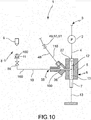
figure 10 is a diagrammatic view of an abrasive water-jet cutting machine, according to a further embodiment of the invention. - With reference to the drawings, an abrasive water-jet cutting machine according to the invention is generally indicated by
reference numeral 1. - In accordance with an aspect of the invention, the abrasive water-
jet cutting machine 1 comprises pumping means 2, fluidly connectable to awater source 3, for the generation of apressurized water flow 4. - The cutting
machine 1 further comprises a cuttinghead 5, comprising aprimary nozzle 27, a mixingchamber 6 and a focusingnozzle 7. - According to an aspect of the invention, the
pressurized water flow 4 from the pumping means 2 is conveyed to theprimary nozzle 27 of the cuttinghead 5 where the pressure energy of thepressurized water flow 4 is converted into kinetic energy so as to form awater jet 12, and, subsequently, thewater jet 12 is conveyed into the mixingchamber 6. - The cutting
machine 1 further comprises adispensing system 8 of powdered abrasive material comprising atank 9 containing abrasive material, asupply tube 10, which fluidly connects thetank 9 to the mixingchamber 6 of the cuttinghead 5, and anactuator 11 which delivers the powdered abrasive material contained in thetank 9 into the mixingchamber 6, through thesupply tube 10. - According to a further aspect of the invention, the cutting
head 5 mixes, in the mixingchamber 6, the abrasive material with thewater jet 12 thus forming a water-abrasivematerial mixture jet 13, which is delivered by the cuttinghead 5 through the focusingnozzle 7. - The focusing
nozzle 7 also has the task, upon mixing the abrasive material with thewater jet 12, of increasing the efficiency of the mixing and of the transfer of momentum from thewater jet 12 to the abrasive material. - According to a further aspect of the invention, the powdered abrasive material contained in the
tank 9 is homogeneously dispersed in suspension in a water-basedgelatinous fluid 60. - Therefore, the powdered abrasive material homogeneously dispersed in suspension in the water-based gelatinous fluid 60 forms an
abrasive mixture 160. - According to a further aspect of the invention, the
actuator 11 is aperistaltic pump 100. - Such a configuration of the
dispensing system 8, and in particular of the powdered abrasive material dispensed thereby, allows the control of the hygroscopic properties of the powdered abrasive material. In fact, since the powdered abrasive material is homogeneously dispersed in the water-basedgelatinous fluid 60, it is completely saturated with water, therefore it is immune to the critical issues deriving from the exposure thereof to environmental and process humidity. - Furthermore, since the powdered abrasive material is completely saturated with water and is homogeneously dispersed in the water-based
gelatinous fluid 60, said dispensingsystem 8 delivers the abrasive material regularly and reliably, even at low dosages of abrasive material (less than 20 g/min). - Furthermore, such a
dispensing system 8 is compatible with the use of the cuttingmachine 1 in an "overhead" configuration. - Furthermore, such a
dispensing system 8 also is usable at the pressures required to perform µAWJ-type processes (greater than 380 MPa). - Furthermore, the implementation of a
peristaltic pump 100 ensures a continuous amount ofabrasive mixture 160, without causing wear phenomena in thedispensing system 8. - According to an embodiment of the invention, the
supply tube 10 is made of polymeric material. - Advantageously, the
supply tube 10 made of polymeric material further reduces any wear phenomena in thedispensing system 8, and further attenuates the pressure oscillations caused in the flow ofabrasive mixture 160 by the peristaltic motion induced by theperistaltic pump 100. - According to an embodiment, the cutting
machine 1 comprises anair duct 110 which converges into the mixingchamber 6. - Advantageously, the supply of air by means of the
air duct 110 avoids the risk that the vacuum generated inside the mixingchamber 6 disturbs the amount of theabrasive mixture 160 introduced therein. - With a further advantage, the supply of air to the mixing
chamber 6 through the air duct is self-stabilized, i.e., it does not require an external adjustment. - According to an embodiment of the invention, the cutting
machine 1 comprises anelectronic controller 120. - The
electronic controller 120 is configured to adjust the amount ofabrasive mixture 160 delivered by thedispensing system 8. - The
electronic controller 120 can be, for example, a PC or a PLC. - Advantageously, the use of an
electronic controller 120 further improves the precision of the dosage ofabrasive mixture 160. - According to an embodiment, the
tank 9 contains theabrasive mixture 160, in which the powdered abrasive material is homogeneously dispersed within the water-basedgelatinous fluid 60. - According to an embodiment, the
electronic controller 120 is configured to adjust the amount ofabrasive mixture 160 delivered by theactuator 11, through an open-loop control 180. - Advantageously, the
electronic controller 120 adjusts the amount ofabrasive mixture 160 by adjusting the speed of theperistaltic pump 100. Following this adjustment, thedispensing system 8 self-stabilizes, so as to deliver a regulated and continuous amount ofabrasive mixture 160 to the mixingchamber 6. - In particular, the relationship between the speed of the
peristaltic pump 100 and the amount of theabrasive mixture 160 is given by calibration curves obtained with experimental tests for each type of abrasive mixture. - According to a further embodiment of the invention, the
tank 9 comprises at least afirst tank 130 containing water-basedgelatinous fluid 60, and at least asecond tank 140 containing powdered abrasive material. - Furthermore, the
dispensing system 8 comprises amixer 150 interposed between thetank 9 and theactuator 11. That is, themixer 150 is placed at least downstream of the at leastfirst tank 130 andsecond tank 140, and upstream of theactuator 11, with reference to the flow direction ofabrasive mixture 160. - The
mixer 150 is configured to mix the water-basedgelatinous fluid 60 contained in the at least afirst tank 130 with the powdered abrasive material contained in the at least asecond tank 140, so as to form anabrasive mixture 160, and convey theabrasive mixture 160 into theactuator 11. - Advantageously, a
tank 9 thus configured avoids preparing the abrasive mixture in a separate step, and subsequently introducing it into the tank, with the risk of introducing and forming air bubbles which would cause drastic local reductions in the amount of abrasive. - This risk is considerably reduced through a direct "in-line" preparation of the
abrasive mixture 160 carried out by means of at least two separate tanks and a mixer. - With further advantage, such a direct production of the
abrasive mixture 160 allows a high control over various properties of theabrasive mixture 160, such as composition, proportions, and rheology. - With further advantage, a
tank 9 thus configured also allows mixing different powdered abrasives, which can be contained in severalsecond tanks 140, even continuously during the cutting performed by the cuttingmachine 1. - According to an advantageous embodiment, the
dispensing system 8 comprises athird tank 200 downstream of the at leastfirst tank 130, the at leastsecond tank 140 and themixer 150. Thethird tank 200 is configured to contain theabrasive mixture 160 prepared by themixer 150, and to convey it towards theactuator 11. - According to an embodiment of the invention, the cutting
machine 1 comprises apulsation damper 170 fluidly connected to thesupply tube 10. - Advantageously, the
pulsation damper 170 further adjusts the amount ofabrasive mixture 160 to be introduced into the mixingchamber 6, further dampening the pressure oscillations of theabrasive mixture 160 conveyed by thesupply tube 10, and consequently increasing the precision of the cutting process performed by the cuttingmachine 1. - According to an advantageous embodiment, the
pulsation damper 170 is a gas, or diaphragm, or spring, or weight hydraulic accumulator. - According to an embodiment of the invention, the
electronic controller 120 is configured to adjust the amount ofabrasive mixture 160 delivered by themixer 150. Alternatively, or in addition, theelectronic controller 120 is configured to adjust the amount ofabrasive mixture 160 delivered by theactuator 11. Alternatively, or in addition, theelectronic controller 120 is configured to adjust the air amount introduced from theair duct 110 into the mixingchamber 6. Alternatively, or in addition, theelectronic controller 120 is configured to adjust the actuation of thepulsation damper 170. - Advantageously, this ensures high adjustment and precision of the amount of
abrasive mixture 160 introduced into the mixingchamber 6. - According to an advantageous embodiment, the
electronic controller 120 is configured to carry out the aforesaid adjustments by means of a closed-loop control 190. - Advantageously, a closed-loop control of one or more of the aforesaid parameters ensures a further improvement in the adjustment and precision of the amount of
abrasive mixture 160 conveyed into the mixingchamber 6. - According to a preferred embodiment, in the
abrasive mixture 160, the mass ratio of the powdered abrasive material and the water-basedgelatinous fluid 60 in which the powdered abrasive material is homogeneously dispersed in suspension is between 1.0 and 3.5. - According to a preferred and advantageous embodiment, in the
abrasive mixture 160, the ratio of the powdered abrasive material and the water-basedgelatinous fluid 60 in which the powdered abrasive material is homogeneously dispersed in suspension is between 2.0 and 3.5. - According to a preferred and advantageous embodiment, in the
abrasive mixture 160, the ratio of the powdered abrasive material and the water-basedgelatinous fluid 60 in which the powdered abrasive material is homogeneously dispersed in suspension is about 2.0. - Advantageously, by virtue of such a dosage of powdered abrasive material homogeneously dispersed in the water-based
gelatinous fluid 60, thedispensing system 8 uses a smaller amount of dispersion substance with respect to the dispensing systems of abrasive material according to the ASJ technology, to adequately deliver a greater amount of powdered abrasive material. - According to an embodiment, the
supply tube 10 is connected to the cuttinghead 5 by means of aninjector nozzle 38, and theinjector nozzle 38 protrudes inside the mixingchamber 6. - Advantageously, this allows to convey the
abrasive mixture 160 in the immediate vicinity of thewater jet 12, so that the conveyedabrasive mixture 160 does not accumulate on the walls of the mixingchamber 6, nor is it suddenly released. - According to an embodiment, the particle size of the powdered abrasive material homogeneously dispersed in suspension in the water-based
gelatinous fluid 60 is less than #200 mesh, preferably between #350 mesh and #600 mesh. - The average size of the granules of powdered abrasive material is less than 70 micrometers, preferably between 15 and 60 micrometers.
- The nature and chemical composition of the abrasive used can be of different types, for example natural minerals such as Almandine Garnet or Olivine, synthetics, ceramics such as Silicon Carbide, metal compounds, biological material.
- The water-based
gelatinous fluid 60 is composed of distilled water and a gelling agent (e.g., a polymer) in sufficient amounts to keep the mixture in suspension without the granules of powdered abrasive material settling on the bottom of thetank 9. - According to an embodiment of the invention, the cutting
head 5 comprises a mixingchamber 6 of a substantially tubular shape, which forms afront surface 14, arear surface 15 parallel to thefront surface 14, and aperipheral surface 29. - The terms "front" and "rear" refer to the flow direction of
pressurized water 4 passing through the cuttinghead 5. - The mixing
chamber 6 forms afront seat 16 at thefront surface 14, and arear seat 17 at therear surface 15, in which the front andrear seats - Furthermore, the mixing
chamber 6 forms a water inlet opening 18 at thefront seat 16, and a mixture outlet opening 19 at therear seat 17. - The mixing
chamber 6 forms ajet channel 20, transverse to thefront surface 14 and to therear surface 15, and in flow communication with thefront seat 16 and therear seat 17 by means of thewater inlet opening 18 and themixture outlet opening 19. - The
jet channel 20 and thefront seat 16 form afront shoulder 21 at thewater inlet opening 18. Furthermore, thejet channel 20 and therear seat 17 form arear shoulder 22 at themixture outlet opening 19. - There is a
primary nozzle housing 23 inside thefront seat 16, abutting thefront shoulder 21. - The
primary nozzle housing 23 has a substantially cylindrical shape and defines afront base 24 and arear base 25, in which therear base 25 abuts against thefront shoulder 21. - The
primary nozzle housing 23 forms aprimary nozzle seat 26 at thefront base 24. - There is a
primary nozzle 27 in theprimary nozzle seat 26. Theprimary nozzle 27 transforms the flow ofpressurized water 4 from the pumping means 2 into thewater jet 12. - The focusing
nozzle 7 forms a focusingchannel 28 adapted to concentrate thewater jet 12. - The focusing
nozzle 7 is arranged in therear seat 17 by interference locking. Advantageously, this interference locking ensures the correct centering and positioning of the focusingnozzle 7 with respect to theprimary nozzle 27. - The mixing
chamber 6 forms an injection opening 30 at theperipheral surface 29, and the injection opening 30 is transverse to thejet channel 20 and fluidly connected to thejet channel 20. - The cutting
head 5 further comprises a retainingflange 31, forming acavity 32 which receives and seals the mixingchamber 6 therein. Furthermore, the retainingflange 31 forms a second injection opening 33, configured concentrically with respect to the injection opening 30 of the mixingchamber 6. - The
injection opening 30 and the second injection opening 33 allow, through connection with thesupply tube 10, the injection of the abrasive dispersed in the water-basedgelatinous fluid 60 inside the mixingchamber 6. - According to an embodiment of the invention, the
supply tube 10 is connected at afirst end 34 thereof to thetank 9 and is connected at asecond end 35 thereof to aninjector member 36. - According to an embodiment of the invention, the
injector member 36 comprises aninjector housing 37 and aninjector nozzle 38. - The
injector housing 37 forms aconnection portion 39 adapted to connect theinjector member 36 to thesupply tube 10. - Furthermore, the
injector housing 37 forms a shapedchannel 40 therein, adapted to receive theinjector nozzle 38. - The
injector nozzle 38 forms aninjection channel 41 therein, and anend portion 45 of theinjector nozzle 38 is configured to protrude into thejet channel 20 of the mixingchamber 6, so that theinjection channel 41 places thesupply tube 10 in fluid connection with thejet channel 20. - According to an embodiment of the invention, the
end portion 45 of theinjector nozzle 38 extends by a fraction of a millimeter, preferably 0.5 mm, inside thejet channel 20. Advantageously, this allows the abrasive, dispersed in the water-basedgelatinous fluid 60, to be conveyed in the immediate vicinity of thewater jet 12. Consequently, the conveyed abrasive does not accumulate on the walls of thejet channel 20 and is not suddenly released. - The positioning and connection of the
injector nozzle 38 to the mixingchamber 6 is ensured through a threaded joint, bayonet connection or other attachment system which ensures strength and complete sealing. - According to an embodiment of the invention, the shaped
channel 40 comprises anend portion 42 forming anair injection channel 43 concentric to theend portion 42, and acoupling portion 61 adapted to obtain a shape coupling with theinjector nozzle 38. - Advantageously, the concentric configuration of the
air injection channel 43 with respect to theend portion 42 reduces the dimensions of theinjector member 36. - With further advantage, the concentric configuration of the
air injection channel 43 allows an optimal projection of the abrasive material dispersed in the water-basedgelatinous fluid 60 towards thewater jet 12, keeping theair injection channel 43 clean and functioning. - The
air injection channel 43 forms agap 44, between theair injection channel 43 and theend portion 45 of theinjector nozzle 38. - Furthermore, the
injector housing 37 forms anair flow channel 47 flowing into theair injection channel 43 and forming aconnection seat 46. - The
air flow channel 47 is connected to apneumatic duct 48 at theconnection seat 46. Advantageously, the inner diameter of thepneumatic duct 48 is substantially identical to the diameter of theair flow channel 47, so as to avoid steps which can negatively impact the air flow. - According to an embodiment, the
air duct 110 comprises theair injection duct 43, theair flow duct 47 and thepneumatic duct 48. - There is a valve 49 on the
pneumatic duct 48 for adjusting the air flow entering theair flow channel 47. The air flow entering theair flow channel 47 is sucked in by the passage of thewater jet 12 by Venturi effect. - Furthermore, a pressure gauge 50 and a flow meter 51 (analogue or digital) are arranged on the
pneumatic duct 48, adapted to monitor and allow the control of the air flow introduced into thepneumatic duct 48. - Advantageously, by means of the adjustment valve 49 it is possible to reduce the air amount entering the
pneumatic duct 48, so as to reduce the air dosage of thewater jet 12. Thereby, the Venturi effect generated by thewater jet 12 can be propagated to the abrasive dispersed in the water-basedgelatinous fluid 60, which can therefore be sucked into the mixingchamber 6 without the intervention of any upstream thrust. - Such a configuration of the
pneumatic duct 48 also is usable for checking the assembly of the cuttinghead 5, for monitoring the state of wear of the components (for example theinjector nozzle 38, theprimary nozzle 27, the mixingchamber 6 and the focusing nozzle 7) and for the real-time verification of the correct execution of the cut. - To perform the assembly check, the access of air to the mixing
chamber 6 must be completely blocked, so as to measure the level of pressure generated inside the mixingchamber 6 by the passage of thewater jet 12. Pressure values greater than, equal to or close to the atmospheric value indicate an incorrect alignment of the components, with probable contact between thewater jet 12 and the channel and the inner walls of thejet channel 20 or of the focusingnozzle 7. Values closer to vacuum (for example 0.2 or 0.1 absolute bar) indicate a valid alignment of the components, which generate a significant Venturi effect. - To check the state of wear of the components, the pressure variations in the mixing
chamber 6 over a prolonged period must be recorded in order to determine the wear drift of the components of the cuttinghead 5. In particular, a less accentuated Venturi effect in thejet channel 20 reveals the progressive wear of the primary nozzle, with a consequent decrease in the outflow speed of thewater jet 12. - In order to verify that the cut has been performed correctly in real time, the pressure variations in the mixing chamber must be recorded. Such events are attributable to malfunctions in the dispensing systems of the
water jet 12, of the abrasive dispersed in the water-basedgelatinous fluid 60, or of the air introduced through theair flow channel 47. By evaluating these phenomena, the correct function of thewater jet 12 is determined at all times, so as to predict the success of the cutting operation and, if otherwise, stop the cutting. - According to an embodiment of the invention, the
tank 9 is a substantially cylindrically-shaped container. - According to a preferred embodiment, the
tank 9 is configured in the shape of a syringe, and comprises acylindrical portion 52, inside which the abrasive material dispersed in the water-basedgelatinous fluid 60 is loaded and stored, and acannula portion 53. - According to an embodiment, the
actuator 11 is configured as athrust member 54 which is slidably arranged inside thecylindrical portion 52, and is configured to push the abrasive material dispersed in the water-basedgelatinous fluid 60 contained in thecylindrical portion 52 of thetank 9 towards thecannula portion 53. - The
cannula portion 53 is connected to thefirst end 34 of thesupply tube 10 so as to obtain a fluid connection between thetank 9 and thesupply tube 10. - According to a preferred embodiment, the
thrust member 54 is configured to impart a thrust pressure of approximately 1 relative bar. - Advantageously, using such a pressure value causes the abrasive material dispersed in the water-based
gelatinous fluid 60 to be substantially incompressible, therefore the advancement speed of the thrust member is easily and directly correlated to the delivered amount of abrasive material dispersed in the water-basedgelatinous fluid 60. - According to a further embodiment, the
dispensing system 8 comprises an auxiliary refilling syringe, adapted to refill thetank 9 "in real time", i.e., refilling thetank 9 with new abrasive material dispersed in the water-basedgelatinous fluid 60 simultaneously with the execution of a cutting process by thesame cutting machine 1. - Preferably, such a "real-time" replenishment is performed in a lapse of time between the processing of two successive geometries belonging to the same component being made or to different components.
- According to a further embodiment, the
dispensing system 8 comprises an abrasive tank dedicated to the storage of abrasive material and a gel tank dedicated to the storage of water-based gelatinous fluid, in which the simultaneous mixing and pressurization of the abrasive material with the water-based gelatinous fluid occurs in thesupply tube 10, through a "turbulent" path. - Advantageously, the filling of the
tank 9 occurs at the source through an auxiliary actuator to avoid the presence of air or other gas bubbles at the origin. - Furthermore, a
rear discharge valve 56 is arranged on thethrust member 54 which expels air bubbles or other gases present in the water-basedgelatinous fluid 60 inside which the abrasive material is dispersed, which could introduce compressibility or cause interruptions in the supply of the abrasive material dispersed in the water-basedgelatinous fluid 60 to the cuttinghead 5. - The
thrust member 54 is connected to amotor 58, preferably an electric motor, through atransmission 57. - According to a preferred embodiment, a flow cut-off
valve 59 is connected to thesupply tube 10. The flow cut-offvalve 59 has the purpose of interrupting or diverting the flow of the abrasive material dispersed in the water-basedgelatinous fluid 60 in an emergency. - Advantageously, it is thereby possible to stop the injection of abrasive material dispersed in the water-based
gelatinous fluid 60 into the cuttinghead 5, even if thedispensing system 8 continues the delivery of abrasive material dispersed in the water-based gelatinous fluid 60 from thetank 9. - With further advantage, the flow cut-off
valve 59 has the auxiliary function of interrupting any rising flows from the cuttinghead 5, for example air or water if the focusingnozzle 7 is blocked, so as to protect thedispensing system 8 from overpressure damage. - In a further aspect, the present invention relates to a composition comprising a powdered abrasive material homogeneously dispersed in suspension in a water-based
gelatinous fluid 60, in which the mass ratio of dispersed powdered abrasive material and the water-basedgelatinous fluid 60 is between 1.0 and 3.5, or between 2.0 and 3.5, or about 2.0 and in which the particle size of the powdered abrasive material homogeneously dispersed in suspension in the water-basedgelatinous fluid 60 is between #350 mesh and #600 mesh. - Preferably, the average granule size of the abrasive material in said composition is between 15 and 60 micrometers.
- A further aspect according to the present invention is an abrasive water-jet cutting method, where said method comprises the use of the abrasive composition according to the present invention.
- According to an embodiment, the abrasive water-jet cutting method comprises the steps of:
- providing an abrasive water-
jet cutting machine 1 as described above, - adjusting the amount of
abrasive mixture 160 delivered by theactuator 11 by means of an open-loop control 180. - According to a further embodiment, the abrasive water-jet cutting method comprises the steps of:
- providing an abrasive water-
jet cutting machine 1 as described above, - performing at least one of the following adjustments by means of a closed-loop control 190:
- adjustment of the amount of
abrasive mixture 160 delivered by themixer 150; - adjustment of the amount of
abrasive mixture 160 delivered by theactuator 11; - adjustment of the air amount introduced from the
air duct 110 into the mixingchamber 6; - adjustment of the actuation of the
pulsation damper 170.
- adjustment of the amount of
- Obviously, in order to meet contingent specific needs, those skilled in the art will be able to make further changes and variations all contained within the scope of protection as defined by the claims.
- Some experimental tests carried out with the abrasive water-jet cutting machine and the composition comprising the abrasive claimed herein will be described below, aimed at highlighting the effectiveness and technical advantages thereof.
- The cutting test is performed on 2.0 mm thick austenitic stainless steel (
AISI 301 / EN 1.4310), to verify the performance of the claimed cutting machine on a relatively thick material. - In fact, 2.0 mm is close to the maximum thickness which can be effectively cut with cutting machines in the µAWJ field of the state of the art known to the inventors.
- The geometry of the cut groove and the roughness of the cut wall surface are measured at different depth levels:
- 0.2 mm from the top ("top")
- at half height (1.0 mm, "mid")
- 0.2 mm from the bottom ("bot")
- The following Tables 1.1 and 1.2 report the results obtained from the test:
Table 1.1: cutting tests on 2 mm thick austenitic stainless steel ( AISI 301 / EN 1.4310). Macro-geometric check of the cutting wall with varying advancement speeds.2.0 mm thick austenitic stainless steel ( AISI 301 / EN 1.4310) Cut groove width inspectionv f [mm/min] W top [mm] W bot [mm] W average [mm] Taper [mm] 3 0.187 0.221 0.204 -0.015 6 0.172 0.158 0.165 0.007 9 0.171 0.145 0.158 0.013 12 0.165 0.128 0.146 0.018 15 0.164 0.116 0.140 0.024 18 0.157 0.108 0.133 0.024 21 0.153 0.093 0.123 0.030 24 0.152 0.090 0.121 0.031 v f: head advancement speed
W top: upper groove width
W bot: lower groove width
W average: average groove width
Taper: inclination of the single wallTable 1.2: cutting tests on 2 mm thick austenitic stainless steel ( AISI 301 / EN 1.4310). Roughness check of the cutting wall with varying advancement speeds.2.0 mm thick austenitic stainless steel ( AISI 301 / EN 1.4310) Roughness inspectionv f [mm/min] R a top [µm] R a mid [µm] R a bot [µm] R a average [µm] R z top [µm] Rz mid [µm] Rz bot [µm] Rz average [µm] 3 0.36 0.44 0.56 0.45 3.02 3.15 4.00 3.38 6 0.38 0.49 0.64 0.51 3.28 3.95 5.01 4.01 9 0.42 0.48 0.64 0.51 3.61 3.70 4.77 3.92 12 0.44 0.59 0.81 0.67 3.77 4.34 5.90 5.05 15 0.47 0.66 0.96 0.72 3.98 5.16 6.47 5.25 18 0.49 0.83 1.27 0.90 3.90 6.69 8.15 6.57 21 0.50 0.94 1.53 1.04 3.98 6.33 9.20 6.79 24 0.64 1.29 2.32 1.52 5.05 9.27 14.73 9.91 v f: head advancement speed
R a top: arithmetic average roughness near the upper surface of the piece
R a mid: arithmetic average roughness at half thickness of the piece
R a bot: arithmetic average roughness near the lower surface of the piece
R a average: average of the R a values detected
R z top: roughness on the 10 extreme points near the upper surface of the piece
R z mid: roughness on the 10 extreme points at half thickness of the piece
R z bot: roughness on the 10 extreme points near the lower surface of the piece
R z average: average of the R z values detected - Two operating conditions are revealed by the test:
- a full but irregular cut is made at high vf = 24 mm/min;
- a high-quality cut is made at lower vf, among which vf = 6 mm/min is an ideal value as it minimizes the inclination of the wall, making both sides of the cut usable with a tolerance of 1 hundredth of a millimeter, without having to introduce head inclinations to compensate for the defect.
- The new system proves effective in cutting thick metal plates (at least by abrasive micro-jet standards) at different levels of vf and also in drilling with different strategies.
- A complex shape is chosen for a complete characterization of the new performance of the system. This is the letter "A" in a particular character, used as a reference piece, as it contains:
- straight lines, for measuring roughness and streaks due to irregularities in the formation of the jet;
- acute angles, both inner and outer, to show the precision of the jet in defining the edges with a low "jet lag" effect;
- small radius curves, to show the radius limit which can be reached according to the size of the jet;
- thin walls, to demonstrate the high stability and delicacy of the jet;
- long processing path, as a resistance test of system stability and robustness.
- The smallest A obtainable with the focusing nozzle df = 0.20 mm and the #230 mesh abrasive, the minimum jet size currently available in the micro AWJ commercial panorama, is 12 mm high and has a minimum radius of 0.12 mm. For the present study, the design is scaled down to 75%, thus achieving a final height of 9 mm and a minimum radius of 0.09 mm.
- Table 2 summarizes the main processing parameters for the execution of this reference piece, cut with the claimed cutting machine, replicating the complete execution of the cutting program three times.
Table 2: process configuration and parameters for making the sample in 2 mm thick austenitic stainless steel ( AISI 301 / EN 1.4310).Parameter / Operation Value / Strategy Primary nozzle diameter [mm] 0.05 Focusing nozzle diameter 0.13 Hydraulic pressure [MPa] 350 Abrasive [type and mesh] Garnet #600 mesh Abrasive amount [q/min] 3 Mixing chamber pressure [bar] 0.78 - 0.80 Advancement speed [mm/min] 6 Drilling strategy Circular Drilling time [s] 4 Distance from the piece being drilled [mm] 1.2 Distance from the piece being cut [mm] 0.2 Cutting length [mm] 90 Cutting time [min] 15 - The sample is then detached from the base material to be observed and measured.
Figure 6 shows the resulting sample in top view, where the precision and accuracy resulting from the cut can be observed. The sample is used to evaluate the width of the cut in different cutting directions, showing no significant variation in all the measurements. - The comparison between the abrasive water-jet cutting machine according to the invention and an abrasive water-jet cutting machine according to the state of the art is shown here, in the execution of a cut of a sample of 2 mm thick austenitic stainless steel (
AISI 301 / EN 1.4310). - The technical specifications of the abrasive water-jet cutting machine according to the invention and of the abrasive water-jet cutting machine according to the state of the art are listed in Table 3.1, while the results obtained following the test are reported in Table 3.2.
- As evidenced by Tables 3.1 and 3.2, and as seen in
Figure 7 , the abrasive water-jet cutting machine according to the invention boasts improvements with respect to the prior art, as regards the quality of the cutting groove, with cutting width reduced by 35%, and roughness quality, with Ra and Rz reduced by 57%. - Furthermore, the abrasive water-jet cutting machine according to the invention has obtained such results respecting the tolerance of 1 hundredth of a millimeter on the inclination of the wall (taper).
Table 3.1: Technical specifications Background art Cutting machine according to the invention Primary nozzle diameter [mm] 0.08 0.05 Focusing nozzle diameter [mm] 0.20 0.13 Hydraulic pressure [MPa] 350 350 Abrasive Garnet Garnet Abrasive mesh [# mesh] #230 mesh #600 mesh Distance from the piece [mm] 0.35 0.20 Table 3.2: Test results Background art Cutting machine according to the invention Groove width [mm] 0.245 0.159 Wall inclination [mm] -0.001 0.007 Roughness Ra [µm] top 1.10; mid 1.25; bot 1.38 top 0.37; mid 0.51; bot 0.65 Roughness Rz [µm] top 8.77; mid 8.80; bot 9.87 top 3.17; mid 3.83; bot 4.62 - Obviously, in order to meet contingent specific needs, those skilled in the art will be able to make further changes and variations all contained within the scope of protection defined by the following claims.
in which the powdered abrasive material delivered in the mixing chamber is homogeneously dispersed in suspension in a water-based gelatinous fluid;
and in which the actuator is a peristaltic pump.
Such a configuration of the dispensing system, and in particular of the abrasive material dispensed thereby, allows the control of the hygroscopic properties of the abrasive material. In fact, since the powdered abrasive material is homogeneously dispersed in the water-based gelatinous fluid, it is completely saturated with water, therefore it is immune to the critical issues deriving from the exposure thereof to environmental and process humidity.
Claims (14)
- An abrasive water-jet cutting machine (1), comprising:- pumping means (2), fluidly connectable to a water source (3), for the generation of a pressurized water flow (4);- a cutting head (5), comprising a primary nozzle (27), a mixing chamber (6) and a focusing nozzle (7),
wherein the pressurized water flow (4) from the pumping means (2) is conveyed into the primary nozzle (27) of the cutting head (5) where the pressure energy of the pressurized water flow (4) is converted into kinetic energy so as to form a water jet (12), and wherein said water jet (12) is then conveyed into the mixing chamber (6);- a dispensing system (8) of powdered abrasive material, comprising:- a tank (9) containing powdered abrasive material,- a supply tube (10), which fluidly connects the tank (9) to the mixing chamber (6) of the cutting head (5),- an actuator (11) interposed between the tank (9) and the supply tube (10), which delivers the powdered abrasive material contained in the tank (9) into the mixing chamber (6), through the supply tube (10);wherein the cutting head (5) mixes, in the mixing chamber (6), the abrasive material with the water jet (12), thus forming a water-abrasive material mixture jet (13), and said cutting head (5) delivers the water-abrasive material mixture jet (13), through the focusing nozzle (7);
wherein the powdered abrasive material delivered in the mixing chamber (6) is homogeneously dispersed in suspension in a water-based gelatinous fluid (60);
and wherein the actuator (11) is a peristaltic pump (100). - A cutting machine (1) according to claim 1, wherein the supply tube (10) is made of polymer material.
- A cutting machine (1) according to claim 1 or 2, comprising an air duct (110) which converges into the mixing chamber (6).
- A cutting machine (1) according to one of claims 1 to 3, comprising an electronic controller (120) configured to adjust the amount of abrasive mixture (160) delivered by the dispensing system (8).
- A cutting machine (1) according to one of claims 1 to 4, wherein the tank (9) contains an abrasive mixture (160).
- A cutting machine (1) according to claim 4 or 5, wherein the electronic controller (120) is configured to adjust the amount of abrasive mixture (160) delivered by the actuator (11), through an open-loop control (180).
- A cutting machine (1) according to one of claims 1 to 4, wherein the tank (9) comprises at least a first tank (130) containing water-based gelatinous fluid (60), and at least a second tank (140) containing powdered abrasive material,
and wherein the dispensing system (8) comprises a mixer (150) interposed between the tank (9) and the actuator (11), and configured to mix the water-based gelatinous fluid (60) contained in the at least a first tank (130) with the powdered abrasive material contained in the at least a second tank (140), so as to form an abrasive mixture (160), and convey the abrasive mixture (160) into the actuator (11). - A cutting machine (1) according to any one of the preceding claims, comprising a pulsation damper (170) fluidly connected to the supply tube (10).
- A cutting machine (1) according to claim 4 and according to one of claims 3, 7 and 8, wherein the electronic controller (120) is configured to adjust:- the amount of the abrasive mixture (160) delivered by the mixer (150) and/or- the amount of the abrasive mixture (160) delivered by the actuator (11) and/or- the air amount introduced from the air duct (110) into the mixing chamber (6) and/or- the actuation of the pulsation damper (170).
- A cutting machine (1) according to claim 9, wherein the electronic controller (120) is configured to carry out the adjustment by means of a closed-loop control (190).
- A cutting machine (1) according to any one of the preceding claims, wherein, in the abrasive mixture (160), the mass ratio of the powdered abrasive material to the water-based gelatinous fluid (60) is between 1.0 and 3.5.
- A cutting machine (1) according to any one of the preceding claims, wherein the supply tube (10) is connected to the cutting head (5) by means of an injector nozzle (38), and wherein the injector nozzle (38) protrudes into the mixing chamber (6).
- An abrasive waterjet cutting method, comprising the steps of:- providing an abrasive waterjet cutter according to one of the preceding claims and according to claim 4;- adjusting the amount of the abrasive mixture (160) delivered by the actuator (11) by means of an open-loop control (180).
- An abrasive waterjet cutting method, comprising the steps of:- providing an abrasive waterjet cutter according to one of the preceding claims and according to claims 4 and 9;- performing at least one of the following adjustments by means of a closed-loop control (190):- adjustment of the amount of abrasive mixture (160) delivered by the mixer (150);- adjustment of the amount of abrasive mixture (160) delivered by the actuator (11);- adjustment of the air amount introduced from the air duct (110) into the mixing chamber (6);- adjustment of the actuation of the pulsation damper (170).
Applications Claiming Priority (1)
| Application Number | Priority Date | Filing Date | Title |
|---|---|---|---|
| IT102020000006010A IT202000006010A1 (en) | 2020-03-20 | 2020-03-20 | Abrasive water jet cutting machine |
Publications (1)
| Publication Number | Publication Date |
|---|---|
| EP3881970A1 true EP3881970A1 (en) | 2021-09-22 |
Family
ID=70805111
Family Applications (1)
| Application Number | Title | Priority Date | Filing Date |
|---|---|---|---|
| EP21161182.7A Pending EP3881970A1 (en) | 2020-03-20 | 2021-03-08 | Abrasive water-jet cutting machine |
Country Status (3)
| Country | Link |
|---|---|
| US (1) | US20210291319A1 (en) |
| EP (1) | EP3881970A1 (en) |
| IT (1) | IT202000006010A1 (en) |
Citations (10)
| Publication number | Priority date | Publication date | Assignee | Title |
|---|---|---|---|---|
| US20030092364A1 (en) * | 2001-11-09 | 2003-05-15 | International Business Machines Corporation | Abrasive fluid jet cutting composition, method and apparatus |
| US20040097171A1 (en) * | 2001-03-02 | 2004-05-20 | Danek Liwszyc | Generation of abrasive liquid jets |
| KR20100092539A (en) * | 2009-02-13 | 2010-08-23 | 주식회사 마이크로홀 | Micro-abrasive concentrated high-pressured jet, mach-jet |
| US20150031270A1 (en) * | 2012-03-11 | 2015-01-29 | Finepart Sweden Ab | Abrasive jet system |
| US20180080734A1 (en) * | 2016-08-15 | 2018-03-22 | Paul L. Miller | Abrasive Entrainment Waterjet Cutting |
| US20180161958A1 (en) * | 2016-12-12 | 2018-06-14 | Omax Corporation | Recirculation of wet abrasive material in abrasive waterjet systems and related technology |
| CA3058494A1 (en) * | 2017-03-31 | 2018-10-04 | Ant Applied New Technologies Ag | Water-abrasive-suspension cutting system and method for water-abrasive-suspension cutting |
| US20190084125A1 (en) * | 2017-09-21 | 2019-03-21 | Shape Technologies Group, Inc. | Air flow management systems and methods to facilitate the delivery of abrasives to an abrasive fluid jet cutting head |
| US20190105756A1 (en) * | 2017-10-11 | 2019-04-11 | C.M.S. S.P.A. | Water-jet cutting system |
| US20190210188A1 (en) * | 2016-09-28 | 2019-07-11 | Eurowaterjet S.R.L. | Apparatus and method for waterjet cutting |
-
2020
- 2020-03-20 IT IT102020000006010A patent/IT202000006010A1/en unknown
-
2021
- 2021-03-08 EP EP21161182.7A patent/EP3881970A1/en active Pending
- 2021-03-19 US US17/206,462 patent/US20210291319A1/en not_active Abandoned
Patent Citations (10)
| Publication number | Priority date | Publication date | Assignee | Title |
|---|---|---|---|---|
| US20040097171A1 (en) * | 2001-03-02 | 2004-05-20 | Danek Liwszyc | Generation of abrasive liquid jets |
| US20030092364A1 (en) * | 2001-11-09 | 2003-05-15 | International Business Machines Corporation | Abrasive fluid jet cutting composition, method and apparatus |
| KR20100092539A (en) * | 2009-02-13 | 2010-08-23 | 주식회사 마이크로홀 | Micro-abrasive concentrated high-pressured jet, mach-jet |
| US20150031270A1 (en) * | 2012-03-11 | 2015-01-29 | Finepart Sweden Ab | Abrasive jet system |
| US20180080734A1 (en) * | 2016-08-15 | 2018-03-22 | Paul L. Miller | Abrasive Entrainment Waterjet Cutting |
| US20190210188A1 (en) * | 2016-09-28 | 2019-07-11 | Eurowaterjet S.R.L. | Apparatus and method for waterjet cutting |
| US20180161958A1 (en) * | 2016-12-12 | 2018-06-14 | Omax Corporation | Recirculation of wet abrasive material in abrasive waterjet systems and related technology |
| CA3058494A1 (en) * | 2017-03-31 | 2018-10-04 | Ant Applied New Technologies Ag | Water-abrasive-suspension cutting system and method for water-abrasive-suspension cutting |
| US20190084125A1 (en) * | 2017-09-21 | 2019-03-21 | Shape Technologies Group, Inc. | Air flow management systems and methods to facilitate the delivery of abrasives to an abrasive fluid jet cutting head |
| US20190105756A1 (en) * | 2017-10-11 | 2019-04-11 | C.M.S. S.P.A. | Water-jet cutting system |
Also Published As
| Publication number | Publication date |
|---|---|
| US20210291319A1 (en) | 2021-09-23 |
| IT202000006010A1 (en) | 2021-09-20 |
Similar Documents
| Publication | Publication Date | Title |
|---|---|---|
| US9138863B2 (en) | Particle-delivery in abrasive-jet systems | |
| US8342912B2 (en) | Abrasive water jet processing machine | |
| EP2321093B1 (en) | Vented cutting head body for abrasive jet system | |
| US7207868B2 (en) | Cutting apparatus | |
| EP2489470B1 (en) | Method for thin kerf cutting and in-situ recycling | |
| US8308525B2 (en) | Processes and apparatuses for enhanced cutting using blends of abrasive materials | |
| US5407379A (en) | Differential pressure metering and dispensing system for abrasive media | |
| JP5263639B2 (en) | Powder and granular quantity supply device and powder and granular quantity supply method used for blast processing apparatus | |
| BRPI0816751B1 (en) | NOZZLE SYSTEM FOR GENERATING A PRESSURE ABRASIVE WATER JET AND METHOD FOR PRODUCING A PRESSURE ABRASIVE WATER JET USING THE NOZZLE SYSTEM | |
| JP2013215854A (en) | Abrasive water jet nozzle, and abrasive water jet machine | |
| CN103373611A (en) | Pneumatic solids transfer pump | |
| EP3881970A1 (en) | Abrasive water-jet cutting machine | |
| EP3632618B1 (en) | Abrasive water-jet cutting machine and method, and composition comprising abrasive material | |
| US5542873A (en) | Novel media valve | |
| AU2017361108A1 (en) | Media control valve | |
| CN114473883A (en) | Active feeding type abrasive water jet nozzle device | |
| JP2006297568A (en) | Blast nozzle and blast gun with the same | |
| TWI402105B (en) | Method and apparatus for discharging liquid material | |
| WO2019150893A1 (en) | Machining apparatus and machining method | |
| JP7201226B2 (en) | Injection gun for wet blasting | |
| CN111828821A (en) | Gas/oil mist generator | |
| JP2020142338A (en) | Nozzle, blast processing device, blast processing method | |
| US20220362724A1 (en) | Injector device for an apparatus suitable for mixing chemically reactive components | |
| JP2876400B2 (en) | Projection material quantitative supply device | |
| US20210379730A1 (en) | Dry wet blast media blasting system |
Legal Events
| Date | Code | Title | Description |
|---|---|---|---|
| PUAI | Public reference made under article 153(3) epc to a published international application that has entered the european phase |
Free format text: ORIGINAL CODE: 0009012 |
|
| STAA | Information on the status of an ep patent application or granted ep patent |
Free format text: STATUS: THE APPLICATION HAS BEEN PUBLISHED |
|
| AK | Designated contracting states |
Kind code of ref document: A1 Designated state(s): AL AT BE BG CH CY CZ DE DK EE ES FI FR GB GR HR HU IE IS IT LI LT LU LV MC MK MT NL NO PL PT RO RS SE SI SK SM TR |
|
| STAA | Information on the status of an ep patent application or granted ep patent |
Free format text: STATUS: REQUEST FOR EXAMINATION WAS MADE |
|
| 17P | Request for examination filed |
Effective date: 20220131 |
|
| RBV | Designated contracting states (corrected) |
Designated state(s): AL AT BE BG CH CY CZ DE DK EE ES FI FR GB GR HR HU IE IS IT LI LT LU LV MC MK MT NL NO PL PT RO RS SE SI SK SM TR |
|
| P01 | Opt-out of the competence of the unified patent court (upc) registered |
Effective date: 20230615 |
|
| STAA | Information on the status of an ep patent application or granted ep patent |
Free format text: STATUS: EXAMINATION IS IN PROGRESS |
|
| 17Q | First examination report despatched |
Effective date: 20240123 |