EP3881916A1 - Self-propelled toy - Google Patents
Self-propelled toy Download PDFInfo
- Publication number
- EP3881916A1 EP3881916A1 EP20193579.8A EP20193579A EP3881916A1 EP 3881916 A1 EP3881916 A1 EP 3881916A1 EP 20193579 A EP20193579 A EP 20193579A EP 3881916 A1 EP3881916 A1 EP 3881916A1
- Authority
- EP
- European Patent Office
- Prior art keywords
- self
- vehicle body
- propelled toy
- wheels
- battery
- Prior art date
- Legal status (The legal status is an assumption and is not a legal conclusion. Google has not performed a legal analysis and makes no representation as to the accuracy of the status listed.)
- Granted
Links
Images







Classifications
-
- A—HUMAN NECESSITIES
- A63—SPORTS; GAMES; AMUSEMENTS
- A63H—TOYS, e.g. TOPS, DOLLS, HOOPS OR BUILDING BLOCKS
- A63H17/00—Toy vehicles, e.g. with self-drive; ; Cranes, winches or the like; Accessories therefor
-
- A—HUMAN NECESSITIES
- A63—SPORTS; GAMES; AMUSEMENTS
- A63H—TOYS, e.g. TOPS, DOLLS, HOOPS OR BUILDING BLOCKS
- A63H30/00—Remote-control arrangements specially adapted for toys, e.g. for toy vehicles
- A63H30/02—Electrical arrangements
- A63H30/04—Electrical arrangements using wireless transmission
-
- A—HUMAN NECESSITIES
- A63—SPORTS; GAMES; AMUSEMENTS
- A63H—TOYS, e.g. TOPS, DOLLS, HOOPS OR BUILDING BLOCKS
- A63H17/00—Toy vehicles, e.g. with self-drive; ; Cranes, winches or the like; Accessories therefor
- A63H17/26—Details; Accessories
-
- A—HUMAN NECESSITIES
- A63—SPORTS; GAMES; AMUSEMENTS
- A63H—TOYS, e.g. TOPS, DOLLS, HOOPS OR BUILDING BLOCKS
- A63H17/00—Toy vehicles, e.g. with self-drive; ; Cranes, winches or the like; Accessories therefor
- A63H17/26—Details; Accessories
- A63H17/262—Chassis; Wheel mountings; Wheels; Axles; Suspensions; Fitting body portions to chassis
-
- A—HUMAN NECESSITIES
- A63—SPORTS; GAMES; AMUSEMENTS
- A63H—TOYS, e.g. TOPS, DOLLS, HOOPS OR BUILDING BLOCKS
- A63H17/00—Toy vehicles, e.g. with self-drive; ; Cranes, winches or the like; Accessories therefor
- A63H17/26—Details; Accessories
- A63H17/28—Electric lighting systems
-
- A—HUMAN NECESSITIES
- A63—SPORTS; GAMES; AMUSEMENTS
- A63H—TOYS, e.g. TOPS, DOLLS, HOOPS OR BUILDING BLOCKS
- A63H29/00—Drive mechanisms for toys in general
- A63H29/22—Electric drives
-
- A—HUMAN NECESSITIES
- A63—SPORTS; GAMES; AMUSEMENTS
- A63H—TOYS, e.g. TOPS, DOLLS, HOOPS OR BUILDING BLOCKS
- A63H30/00—Remote-control arrangements specially adapted for toys, e.g. for toy vehicles
- A63H30/02—Electrical arrangements
-
- H—ELECTRICITY
- H04—ELECTRIC COMMUNICATION TECHNIQUE
- H04N—PICTORIAL COMMUNICATION, e.g. TELEVISION
- H04N7/00—Television systems
- H04N7/18—Closed-circuit television [CCTV] systems, i.e. systems in which the video signal is not broadcast
-
- A—HUMAN NECESSITIES
- A63—SPORTS; GAMES; AMUSEMENTS
- A63F—CARD, BOARD, OR ROULETTE GAMES; INDOOR GAMES USING SMALL MOVING PLAYING BODIES; VIDEO GAMES; GAMES NOT OTHERWISE PROVIDED FOR
- A63F9/00—Games not otherwise provided for
- A63F9/24—Games using electronic circuits not otherwise provided for
- A63F2009/2401—Detail of input, input devices
- A63F2009/243—Detail of input, input devices with other kinds of input
- A63F2009/2435—Detail of input, input devices with other kinds of input using a video camera
Definitions
- the present invention relates to a self-propelled toy.
- an object of the present invention is to improve the convenience, improve the durability, improve the running performance, etc., so as to improve the user friendliness of the self-propelled toy.
- the present invention it is possible to improve the convenience, improve the durability, improve the running performance, etc., so as to improve the user friendliness of the self-propelled toy.
- FIG. 1 to FIG. 16 a first embodiment of the present invention will be explained.
- FIG. 1 is a perspective view of a self-propelled toy 1 according to the first embodiment of the present invention
- FIG. 2 is a top view of the self-propelled toy 1 according to the first embodiment of the present invention.
- the self-propelled toy 1 has a substantially symmetrical shape about a centerline CL of vehicle width.
- the self-propelled toy 1 includes a vehicle body 2, wheels (front wheels 3 and rear wheels 4) connected to the vehicle body 2, a support arm 5 extending upward from the vehicle body 2, an imaging device 6 supported by the support arm 5, and an operating part 7 and charging port 8 provided at the vehicle body 2.
- the self-propelled toy 1 has an appearance resembling that of an actual vehicle while has a size smaller than an actual vehicle.
- the self-propelled toy 1 is also called a toy vehicle.
- the self-propelled toy 1 has an appearance resembling an automobile and can run on the ground.
- the self-propelled toy 1 includes, as wheels, two front wheels 3 (right front wheel 3a and left front wheel 3b) and two rear wheels 4 (right rear wheel 4a and left rear wheel 4b).
- the front wheels 3 are respectively comprised of a front tire 31 and a front tire wheel 32, while the rear wheels 4 are respectively comprised of a rear tire 41 and a rear tire wheel 42.
- the diameters of the front tire 31 and the front tire wheel 32 are respectively equal to the rear tire 41 and the rear tire wheel 42, and the diameter of the front wheel 3 is equal to the diameter of the rear wheel 4.
- the widths of the front tire 31 and the front tire wheel 32 are respectively smaller than the widths of the rear tire 41 and rear tire wheel 42, and the width of the front wheel 3 is shorter than the width of the rear wheel 4.
- the innermost parts of the rear wheels 4 in the vehicle width direction are positioned at the insides from the innermost parts of the front wheels 3, and the outermost parts of the rear wheels 4 are positioned at the outsides from the outermost parts of the front wheels 3.
- the vehicle body 2 houses components for driving the self-propelled toy 1 and components for controlling the self-propelled toy 1 and protects these components from impact from the outside.
- the vehicle body 2 extends in the front-rear direction from the front from the front wheels 3 to the rear from the rear wheels 4 and extends in the vehicle width direction to the outsides from the front wheels 3 and rear wheels 4. For this reason, the vehicle body 2 can protect the front wheels 3 and rear wheels 4 from impact from the front, rear, left, and right. Further, the front end part of the vehicle body 2 positioned at the front from the front wheels 3 extends to the outside from the innermost parts of the front wheels 3 in the vehicle width direction. Due to this, the front end part of the vehicle body 2 functions as a bumper and can effectively protect the self-propelled toy 1 from impact from the front.
- the vehicle body 2 includes a main cover 21 forming the top part, front part, side parts, and rear part of the vehicle body 2.
- the main cover 21 covers the components housed in the vehicle body 2 so that these components cannot be seen from the outside.
- the main cover 21 functions as the exterior of the self-propelled toy 1 and defines the outer shape of the self-propelled toy 1.
- the vehicle body 2 includes an opening lid 20 covering a charging port 8.
- the opening lid 20 is attached to the main cover 21 to be able to open and close.
- the opening lid 20 together with the main cover 21 forms one side part of the vehicle body 2 (in the present embodiment, the right side part of the vehicle body 2).
- FIG. 1 shows the self-propelled toy 1 when the opening lid 20 is opened.
- the opening lid 20 exposes the charging port 8 to the outside, while when closed, it conceals the charging port 8 from the outside.
- the opening lid 20 is configured to open and close in the vertical direction in a sliding manner.
- the opening lid 20 may be configured to open and close in another opening and closing manner (for example, open and close in a hinge manner or open and close to left and right in a sliding manner).
- the charging port 8 is used for charging a battery provided at the vehicle body 2 and, for example, is configured as a USB connector.
- the charging port 8 is covered by the opening lid 20 so that foreign matter can be kept from entering the charging port 8. Further, the opening lid 20 can protect the charging port 8 from impact from the outside. Note that details of the battery will be explained later.
- the charging port 8 is provided at the side part of the vehicle body 2 at one side from the centerline CL of vehicle width of the self-propelled toy 1, and the opening lid 20 forms the side part of the vehicle body 2 at the same side as the charging port 8 from the centerline CL of vehicle width. Due to this, a user can easily access the charging port 8 from the side of the self-propelled toy 1 through the opening lid 20. Further, when connecting the charging port 8 of the self-propelled toy 1 set horizontally to an outside power source, a connection cord connecting the charging port 8 to the outside power source can be kept from entangling with the wheels 3, 4 etc. Note that, in the present embodiment, the charging port 8 is provided at the right side part of the vehicle body 2, but the charging port 8 may be provided at the left side part of the vehicle body 2.
- the imaging device 6 shown in FIG. 1 is a CMOS (complementary metal oxide semiconductor) camera or a CCD (charge coupled device) camera and is connected to the vehicle body 2 so as to capture an image of the area in front of the self-propelled toy 1.
- CMOS complementary metal oxide semiconductor
- CCD charge coupled device
- the imaging device 6 is connected to the vehicle body 2 through the support arm 5.
- the support arm 5 is connected to the vehicle body 2 between the right rear wheel 4a and the left rear wheel 4b and extends toward the front upward at a slant.
- the imaging device 6 is housed in the support arm 5 and is arranged at a front end part of the support arm 5. As a result, the imaging device 6 is positioned at the topmost part of the self-propelled toy 1 and is positioned in front of the rear wheels 4.
- the front end of the support arm 5 is closed, and the imaging device 6 captures an image of the front area through a transparent or semitransparent part of the support arm 5.
- the support arm 5 and imaging device 6 are arranged at a region near the center in the vehicle width direction (a center region among regions when self-propelled toy 1 is divided into three equal parts in vehicle width direction). Due to this, it is possible to keep the balance of weights of the left and right of the self-propelled toy 1 from deteriorating and in turn possible to keep the running performance of the self-propelled toy 1 from falling.
- the support arm 5 and imaging device 6 are arranged on the centerline CL of vehicle width. Specifically, the support arm 5 and imaging device 6 are arranged so that the center of the imaging device 6 is positioned on the centerline CL of vehicle width. Further, the support arm 5 and imaging device 6 are arranged so that when the self-propelled toy 1 is set horizontal, the optical axis of the imaging device 6 slants downward with respect to the horizontal direction (for example, by 5° to 15°). Due to such placement, in the present embodiment, the front part of the vehicle body 2, the right front wheels 3a, the left front wheels 3b, and the front area of the self-propelled toy 1 are contained in the angle of view of the imaging device 6, and the imaging device 6 captures these.
- FIG. 3 and FIG. 4 are disassembled perspective views of the imaging device 6 of the self-propelled toy 1.
- FIG. 3 shows the front part of the imaging device 6 and the range of capture of the imaging device 6, while
- FIG. 4 shows the rear part of the imaging device 6.
- a camera-use FPC 61 is connected to the imaging device 6.
- the camera-use FPC 61 extends inside the support arm 5 and is connected to a later explained board.
- the self-propelled toy 1 includes a first light emitting diode (LED) 62 emitting blue light and a second light emitting diode (LED) 63 emitting red light.
- the first LED 62 and the second LED 63 are provided at the support arm 5 so as to be visible from the outside. For example, the first LED 62 is turned on when the imaging device 6 is being operated, while the second LED 63 is turned on when the battery is being charged. Due to this, a user can easily grasp the state of the self-propelled toy 1 from a separate location.
- the first LED 62 and the second LED 63 are mounted on the camera-use FPC 61. Therefore, as shown in FIG. 2 , the first LED 62 and the second LED 63 are arranged inside the support arm 5 and are visible from above and behind the self-propelled toy 1 through a transparent or semitransparent part of the support arm 5. As explained above, the imaging device 6, the first LED 62, and the second LED 63 are arranged inside the support arm 5. Due to this, it is possible to keep the user from mistakenly touching these and in turn possible to improve their durabilities.
- the configuration and functions of the LEDs provided at the support arm 5 are not limited to the above.
- the first LED 62 and the second LED 63 may emit different color light.
- one of the first LED 62 and the second LED 63 may be omitted or the first LED 62 and the second LED 63 may be made integral.
- the first LED 62 and the second LED 63 may be connected to the board by wiring (FPC or lead wires) different from the camera-use FPC 61. Further, there may be three or more LEDs.
- the user switches the operating state of the imaging device 6 using the operating part 7 shown in FIG. 1 and FIG. 2 . That is, the operating part 7 is operated by the user for making the imaging device 6 operate. For example, when the imaging device 6 is capturing a still image, the user operates the operating part 7 to determine the shutter timing. Further, when the imaging device 6 captures a moving image, the user operates the operating part 7 to make the imaging device 6 start up. In this case, the operating part 7 is operated to turn on the power of the self-propelled toy 1, and when the operating part 7 is operated or after a predetermined time (for example, several seconds to tens of seconds) after the operating part 7 is operated, image capture by the imaging device 6 is started.
- a predetermined time for example, several seconds to tens of seconds
- the operating part 7 is operated to turn on the power of the self-propelled toy 1, and then image capture by the imaging device 6 may be started based on instruction from an outside apparatus. That is, operation of the operating part 7 may be one of the conditions for start of image capture. In this way, the operating part 7 is operated by the user to directly or indirectly make the imaging device 6 operate. Further, the operating part 7 may also be operated by the user when the user turnes off the power of the self-propelled toy 1.
- the self-propelled toy 1 is basically set on the floor or other running surface. Therefore, the user usually sees the top part of the self-propelled toy 1. Accordingly, in the present embodiment, the operating part 7 is provided on the top part of the vehicle body 2. By doing this, the user frequently sees the operating part 7 and in turn can easily grasp the position of the operating part 7. Further, the user can easily access the operating part 7 from above the vehicle body 2.
- the operating part 7 is provided at the top part of the vehicle body 2 at one side from the centerline CL of vehicle width. Due to this, when the user is holding the self-propelled toy 1 substantially horizontally by his or her two hands to capture an image of the area in front of the self-propelled toy 1, operation of the operating part 7 by one hand becomes easy.
- the operating part 7 is provided at the top right part of the vehicle body 2, specifically at the top right part of the main cover 21.
- the user when using the self-propelled toy 1 to capture an image of an object in front of it, the user can operate the operating part 7 by his or her right hand, while when using the self-propelled toy 1 to capture an image of the user himself or herself, he or she can operate the operating part 7 by his or her left hand.
- the operating part 7 may be provided at the top left part of the vehicle body 2.
- the operating part 7 is, for example, configured as an operating button pressed downward.
- the operating part 7 extends downward from the top surface of the vehicle body 2 and moves in the vertical direction by operation by the user. Further, the operating part 7 is housed in the vehicle body 2 so that the top surface of the operating part 7 becomes flush with the top surface of the vehicle body 2 (in the present embodiment, the top surface of the main cover 21). Due to this, it is possible to reduce the incidence of the operating part 7 being mistakenly operated when the self-propelled toy 1 flips over or is struck without causing a drop in the ease of operation of the operating part 7.
- the charging port 8 is provided at the side part of the vehicle body 2 at the same side as the operating part 7 from the centerline CL of vehicle width.
- the user finds by operation of the operating part 7 that the battery does not have sufficient electric power, for example, if when operating the operating part 7 the self-propelled toy 1 (specifically the imaging device 6 etc.) does not react, it is possible to quickly access the charging port 8 at the same side as the operating part 7 to start charging the battery. Therefore, due to the arrangement of the above-mentioned operating part 7 and charging port 8, the user friendliness of the self-propelled toy 1 can be improved.
- the operating part 7 and charging port 8 are arranged between the front wheels 3 and the rear wheels 4.
- the front wheels 3 can protect the operating part 7 and charging port 8 from impact from the front
- the rear wheels 4 can protect the operating part 7 and charging port 8 from impact from the rear.
- FIG. 5 is a perspective view of the self-propelled toy 1 showing the inside of the vehicle body 2.
- FIG. 5 shows the self-propelled toy 1 when the main cover 21 is detached.
- the vehicle body 2 includes a main chassis 22.
- the main chassis 22 extends in the front-rear direction from the front of the front wheels 3 to the rear of the rear wheels 4 and holds the later explained main components of the self-propelled toy 1.
- the self-propelled toy 1 includes a board 9 on which a plurality of electronic components are mounted.
- the board 9 is attached to the top part of the main chassis 22, and the main chassis 22 holds the board 9.
- the board 9 is fixed by screws 201 to the top part of the main chassis 22.
- the board 9 extends between the front wheels 3 and the rear wheels 4 and extends in the vehicle width direction from the right front wheel 3a and the right rear wheel 4a to the left front wheel 3b and the left rear wheel 4b.
- the above-mentioned support arm 5 is connected to the main chassis 22 at the rear from the board 9. Specifically, the support arm 5 is connected to the main chassis 22 between the right rear wheel 4a and the left rear wheel 4b.
- the support arm 5 has a fastening part 51 arranged inside the main cover 21 and is fixed through the fastening part 51 by screws 202 to the top part of the main chassis 22.
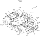
- FIG. 6 is a perspective view of the self-propelled toy 1 showing the inside of the vehicle body 2.
- FIG. 6 shows the self-propelled toy 1 of FIG. 5 when the support arm 5 is detached from the self-propelled toy 1.
- the vehicle body 2 includes a drive part cover 23 covering a later explained drive member and a steering part cover 24 covering a later explained steering member.
- the drive part cover 23 is arranged between the support arm 5 and the main chassis 22 in the vertical direction and is attached to the top part of the main chassis 22 at the rear from the board 9. Specifically, the drive part cover 23 is fixed between the right rear wheel 4a and the left rear wheel 4b by screws 203 to the top part of the main chassis 22.
- the steering part cover 24 is attached to the top part of the main chassis 22 at the front from the board 9. Specifically, the steering part cover 24 is fixed between the right front wheel 3a and the left front wheel 3b by screws 204 to the top part of the main chassis 22.
- FIG. 7 is a left side cross-sectional view of the self-propelled toy 1 along the centerline CL of vehicle width.
- the self-propelled toy 1 includes a drive member 10, a steering member 11, and a battery 12.
- the drive member 10, the steering member 11, and the battery 12 are provided at the vehicle body 2.
- the drive member 10 uses electric power stored in the battery 12 to drive the rear wheels 4.
- the steering member 11 uses the electric power stored in the battery 12 to steer the front wheels 3.
- the battery 12 is a secondary battery able to be charged by an outside power source and, for example, is a lithium ion battery, nickel-hydrogen battery, etc.
- FIG. 8 is a disassembled perspective view of the drive part cover 23 and the rear wheels 4 of the self-propelled toy 1
- FIG. 9 is a view showing the drive member 10 in the drive part cover 23 of FIG. 8 .
- the drive member 10 includes a drive motor 101, pinion gear 102, counter gear 103, spur gear 104, and wheel shaft 105.
- the drive motor 101 uses electric power stored in the battery 12 to output drive power for running use (driving power).
- the drive motor 101 is a DC motor, for example, a brushed motor or a brushless motor.
- the pinion gear 102 is connected to the drive motor 101
- the spur gear 104 is connected to the wheel shaft 105
- the counter gear 103 is arranged between the pinion gear 102 and the spur gear 104.
- the pinion gear 102, the counter gear 103, and the spur gear 104 convert rotation of the drive motor 101 to rotation of the wheel shaft 105.
- the rear wheels 4 are connected to the both ends of the wheel shaft 105 and rotate together with the wheel shaft 105. Therefore, the drive member 10 can drive the rear wheels 4.
- the drive motor 101, the pinion gear 102, the counter gear 103, and the spur gear 104 are housed in the drive part cover 23, while the wheel shaft 105 is connected to the drive part cover 23. Therefore, the drive member 10 is held by the drive part cover 23 and is positioned by the drive part cover 23. That is, since, in the present embodiment, the drive member 10 is positioned by a single component (the drive part cover 23), it is possible to raise the positioning precision among components of the drive member 10.
- the drive member 10 and the rear wheels 4 are connected through the drive part cover 23 to the main chassis 22.
- the main chassis 22 holds the drive member 10 and the rear wheels 4 through the drive part cover 23.
- the drive motor 101 is arranged in a region near the center in the vehicle width direction. Due to this, it is possible to keep the balance of weights of the left and right of the self-propelled toy 1 from deteriorating and in turn possible to keep the running performance of the self-propelled toy 1 from falling.
- FIG. 10 is a partial perspective view of the self-propelled toy 1 showing the inside of the vehicle body 2.
- FIG. 10 shows the front part of the self-propelled toy 1 when the main cover 21 and the steering part cover 24 are detached.
- the steering member 11 includes a steering-use motor 111, a pinion gear 112, a crown gear 113, a sector gear 114, a potentiometer 115, a tie rod 116, and knuckle arms 117.
- the steering-use motor 111, the pinion gear 112, the crown gear 113, the sector gear 114, and the potentiometer 115 are housed in the main chassis 22 and held by the main chassis 22. Further, the tie rod 116, the knuckle arms 117, and the front wheels 3 are connected to the main chassis 22 so that the front wheels 3 can be turned to the left and right. Therefore, the main chassis 22 holds the steering member 11 and the front wheels 3.
- the steering-use motor 111 uses electric power stored in the battery 12 to output drive power for steering use.
- the steering-use motor 111 is a DC motor, for example, a brushed motor or a brushless motor.
- the steering-use motor 111 is arranged in a region near the center in the vehicle width direction.
- the steering-use motor 111 is arranged so that its axis matches the centerline CL of vehicle width. Due to this, it is possible to keep the balance of weights of the left and right of the self-propelled toy 1 from deteriorating and in turn possible to keep the running performance of the self-propelled toy 1 from falling.
- the pinion gear 112 is connected to the steering-use motor 111, the sector gear 114 is connected to the tie rod 116, and the crown gear 113 is arranged between the pinion gear 112 and the sector gear 114.
- the pinion gear 112, the crown gear 113, and the sector gear 114 convert rotation of the steering-use motor 111 to linear motion of the tie rod 116. Due to linear motion of the tie rod 116, the knuckle arms 117 swing back and forth and the orientation of the front wheels 3 connected to the knuckle arms 117 changes to the left and right. Therefore, the steering member 11 can steer the front wheels 3.
- the potentiometer 115 is arranged below the sector gear 114 and detects a rotational angle of the sector gear 114.
- the steering-use motor 111 is controlled based on the output of the potentiometer 115 so that the steering angle of the front wheels 3 becomes the target value. Note that, instead of the steering-use motor 111, the potentiometer 115, etc., a servo motor may be used.
- the drive motor 101 is arranged at the rear from the board 9 and the battery 12, specifically is arranged between the right rear wheel 4a and the left rear wheel 4b.
- the steering-use motor 111 is arranged at the front from the board 9 and the battery 12, specifically is arranged in the front of the front wheels 3.
- the length of the drive motor 101 in the vertical direction is the maximum, and the length of the steering-use motor 111 in the vertical direction is the second most longest. For this reason, it is possible to arrange the drive motor 101 and the steering-use motor 111 in front of and behind the board 9 and the battery 12, and thereby keep the height of the vehicle body 2 from becoming greater.
- FIG. 11 is a bottom view of the wheels 3, 4 and board 9 of the self-propelled toy 1.
- FIG. 11 shows the wheels 3, 4 and board 9 when viewing the self-propelled toy 1 from the bottom.
- the battery 12 positioned below the board 9 is shown by broken lines.
- the board 9 and the battery 12 are arranged so as to at least partially overlap in a horizontal plane (plane shown in FIG. 11 ).
- the board 9 and the battery 12 are arranged so as to at least partially overlap in a top view and a bottom view of the self-propelled toy 1.
- the board 9 and the battery 12 can be reduced in areas occupied compared to when arranging the board 9 and battery 12 side by side on the same plane.
- the length of the board 9 in the longer direction becomes longer than the length of the battery 12 in the shorter direction, while the length of the battery 12 in the longer direction is longer than the length of the board 9 in the shorter direction.
- the area of the board 9 is larger than the area of the battery 12 in a horizontal plane.
- the board 9 and the battery 12 are arranged so as to perpendicularly intersect in the horizontal plane. In this case, compared to when arranging the board 9 and the battery 12 so that the battery 12 fits inside the board 9 in the horizontal plane, the areas occupied by the board 9 and the battery 12 become slightly larger, but the area of the board 9 at the outside of the battery 12 can be made larger.
- the perpendicularly arranged board 9 and battery 12 are arranged so that the longer direction of the board 9 matches the vehicle width direction.
- the length of the board 9 in the longer direction is longer than the length of the battery 12 in the longer direction. For this reason, compared to when arranging the board 9 and the battery 12 so that the longer direction of the board 9 matches the front-rear direction, it is possible to reduce the length of the board 9 and the battery 12 in the front-rear direction.
- the battery 12 is arranged in a region near the center in the vehicle width direction.
- the battery 12 is arranged so that the centerline matches the centerline CL of vehicle width. Due to this, it is possible to keep the balance of weights of the left and right of the self-propelled toy 1 from deteriorating and in turn possible to keep the running performance of the self-propelled toy 1 from falling.
- FIG. 5 and FIG. 6 the electronic components on the top surface of the board 9 will be explained.
- a switch 91 turned on and off by the operating part 7, a first antenna 92 and a second antenna 93 for wireless communication, a wireless communication IC 94 covered by a shield, and a camera-use connector 95 are mounted.
- the board 9 has two side regions (a right side region 90a and a left side region 90b) extending to the outside from the innermost parts of the front wheels 3 and rear wheels 4 in the vehicle width direction.
- the switch 91 and the first antenna 92 are mounted on the top surface of one side region of the board 9 (in the present embodiment, the right side region 90a), while the second antenna 93 and the wireless communication IC 94 are mounted on the top surface of the other side region of the board 9 (in the present embodiment, the left side region 90b).
- the switch 91 is arranged right below the above-mentioned operating part 7 and is turned on and off by the operating part 7. In the present embodiment, the switch 91 is turned on and off when the operating part 7 moves downward to push down the switch 91. When the switch 91 is turned on by the operating part 7, as explained above, the imaging device 6 is directly or indirectly operated.
- the operating part 7 and the switch 91 are separate members, but the operating part 7 and the switch 91 may be integral.
- the operating part 7 and the switch 91 are, for example, configured as a pushbutton switch, a slide switch, a toggle switch, a rocker switch, etc.
- the first antenna 92 and the second antenna 93 for wireless communication are configured in the same way and respectively send and receive electric waves.
- the first antenna 92, the second antenna 93, and the wireless communication IC 94 are configured so as to send data to an outside apparatus and receive data from the outside apparatus.
- the first antenna 92, the second antenna 93, and the wireless communication IC 94 receive control signals for controlling the self-propelled toy 1 from the outside apparatus and send images captured by the imaging device 6 to the outside apparatus. That is, in the present embodiment, the self-propelled toy 1 is a so-called radio-controlled toy vehicle.
- the self-propelled toy 1 sends data toward the outside apparatus above the self-propelled toy 1 and receives data from the outside apparatus above the self-propelled toy 1. For this reason, as explained above, it is possible to raise the communication strength by mounting the first antenna 92 and the second antenna 93 on the top surface of the board 9.
- the first antenna 92 and the second antenna 93 are arranged at the both end parts of the board 9 in the vehicle width direction and are mounted so that axes of the longer directions of the first antenna 92 and the second antenna 93 perpendicularly intersect, whereby it is possible to keep the communication strength from falling along with change of the relative position of the self-propelled toy 1 and outside apparatus.
- the first antenna 92 and the second antenna 93 are mounted at the front end part of the board 9. Therefore, the first antenna 92 is mounted on the top surface of the right side region 90a of the board 9 at the front from the switch 91, while the second antenna 93 is mounted on the top surface of the left side region 90b of the board 9 at the front from the wireless communication IC 94.
- the noise generated from the drive motor 101 can be kept from interfering with wireless communication by the first antenna 92 and the second antenna 93. This advantage is particularly remarkable when the drive motor 101 is a brushed motor with large noise.
- a camera-use FPC 61 is connected to the camera-use connector 95.
- the camera-use FPC 61 is connected to the camera-use connector 95 along the top of the fastening part 51 from the inside of the support arm 5.
- the camera-use connector 95 is mounted on the rear end part of the board 9 in the region near the center in the vehicle width direction and is positioned on the centerline CL of vehicle width.
- the imaging device 6, the first LED 62, and the second LED 63 are electrically connected through the camera-use FPC 61 to the board 9 and are supplied with electric power from the battery 12.
- wiring 301 (two lead wires) of the drive motor 101 is connected to the rear end part of the top surface of the board 9, while wiring 302 (two lead wires) of the steering-use motor 111 and wiring 303 (three lead wires) of the potentiometer 115 are respectively connected to the front end part of the top surface of the board 9.
- the drive motor 101, the steering-use motor 111, and the potentiometer 115 are electrically connected through the wiring to the board 9 and are supplied with electric power from the battery 12.
- the charging port 8 As shown in FIG. 11 , the charging port 8, a control device 96 covered by a shield, an inertial measurement unit (IMU) 97, and a battery-use connector 98 are mounted on the bottom surface of the board 9.
- IMU inertial measurement unit
- the board 9 overlaps the battery 12 in the front-rear direction and has extension parts (a right extension part 100a and a left extension part 100b) extending to the outside from the battery 12 in the vehicle width direction.
- the charging port 8 and the battery-use connector 98 are mounted on the bottom surface of one of the extension parts (in the present embodiment, the right extension part 100a). Due to this, the space at the outside of the battery can be effectively utilized.
- the extension parts 100a, 100b respectively include side regions 90a, 90b extending to the outsides from the innermost parts of the front wheels 3 and rear wheels 4 in the vehicle width direction, and the charging port 8 is mounted on the side region 90a.
- the switch 91, the first antenna 92, the second antenna 93, and the wireless communication IC 94 arranged at the top surface of the board 9 shown in FIG. 5 and FIG. 6 are also mounted on the side regions 90a, 90b.
- the charging port 8 as explained above, is used for charging the battery 12 and supplies electric power from an outside power source to the battery 12. As shown in FIG. 11 , the charging port 8 is arranged at the inside from the outermost parts of the wheels in the vehicle width direction (in the present embodiment, the outermost parts of the rear wheels 4). Due to this, the wheels can protect the charging port 8 from impact from the sides. Further, in the present embodiment, as will be understood from FIG. 2 , the outermost part of the side part of the vehicle body 2 at which the charging port 8 is provided (in the present embodiment, the opening lid 20 and the main cover 21) is positioned at the outside from the outermost part of the wheel in the vehicle width direction. For this reason, the vehicle body 2 can also protect the charging port 8 from impact from the side.
- the outermost parts of the front wheels 3 may be arranged at the outsides from the outermost parts of the rear wheels 4 and the charging port 8 may be arranged at the inside from the outermost parts of the front wheels 3 in the vehicle width direction. Further, the charging port 8 may be arranged at the inside from the outermost parts of the front wheels 3 and the outermost parts of the rear wheels 4 in the vehicle width direction.
- the control device 96 has a CPU etc., and performs various control operations of the self-propelled toy 1.
- the control device 96 is, for example, configured as an SOC (System on Chip) and is electrically connected to other components on the board 9.
- SOC System on Chip
- the control device 96 is arranged at a region near the center of the vehicle width direction. Specifically, it is arranged on the centerline CL of vehicle width. By doing this, it is possible to dissipate heat generated at the control device 96 to the surrounding parts of the board 9 and improve the heat radiating performance of the self-propelled toy 1.
- the IMU 97 includes a three-axis acceleration sensor and a three-axis gyro sensor (angular velocity sensor) and functions as a six-axis sensor detecting the acceleration in three axial directions and angular velocity in three axial directions.
- the control device 96 controls the posture of the self-propelled toy 1 based on the output of the IMU 97.
- the IMU 97 is arranged in a region near the center in the vehicle width direction, specifically, is arranged on the centerline CL of vehicle width. Due to this, it is possible to reduce the effect due to the left-right difference in operation of the self-propelled toy 1. Further, in the present embodiment, the IMU 97 is arranged at the front from the charging port 8, the control device 96, and the battery-use connector 98.
- Wiring of the battery 12 (for example lead wires) is connected to the battery-use connector 98.
- the electric power stored in the battery 12 is connected through the battery-use connector 98 to the board 9.
- the battery-use connector 98 is arranged at the front from the charging port 8 and the control device 96 and is arranged at the inside from the charging port 8 in the vehicle width direction.
- the battery-use connector 98 has the greatest height (thickness) among the electronic components mounted on the bottom surface of the board 9. Therefore, in the present embodiment, the electronic components mounted on the extension parts 100a, 100b of the board 9 are positioned the lowest among the electronic components mounted on the bottom surface of the board 9. For this reason, if, like in the present embodiment, the board 9 is arranged above the battery 12, it is possible to reduce the length in the vertical direction of the board 9 on which the electronic components are mounted and the battery 12. Note that, other electronic components arranged at the extension parts 100a, 100b (for example, the charging port 8) may have the greatest height.
- FIG. 12 is a bottom view of the self-propelled toy 1.
- the vehicle body 2 includes a bottom cover 25.
- the vehicle body 2 is comprised of the opening lid 20, the main cover 21, the main chassis 22, the drive part cover 23, the steering part cover 24, and the bottom cover 25.
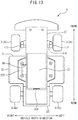
- FIG. 13 is a bottom view of the self-propelled toy 1 showing the battery 12.
- FIG. 13 shows the self-propelled toy 1 when the bottom cover 25 is detached.
- the bottom cover 25 extends in the front-rear direction from the front from the front wheels 3 to the rear wheels 4 and covers the battery 12 so that the battery 12 cannot be seen from the outside.
- the bottom cover 25 is attached to the main chassis 22, and the bottom cover 25 and the main chassis 22 form the bottom part (bottom surface) of the vehicle body 2. Further, the flat bottom surface of the bottom cover 25 forms the bottom surface of the vehicle body 2.
- the board 9 is attached to the top part of the main chassis 22, while as will be understood from FIG. 7 and FIG. 13 , the battery 12 is attached to the bottom part of the main chassis 22.
- the battery 12 which is the heaviest component, near the bottom part of the vehicle body 2, it is possible to lower the center of gravity of the self-propelled toy 1 and in turn possible to improve the running performance of the self-propelled toy 1.
- the user can detach the bottom cover 25 and easily access the battery 12, and therefore replacement and disposal of the battery 12 become easy.
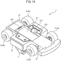
- FIG. 14 is a perspective view of the self-propelled toy 1 showing the bottom part of the main chassis 22.
- FIG. 14 shows the self-propelled toy 1 when the bottom cover 25 and the battery 12 are detached.
- a first recessed part 221 is formed at the bottom part of the main chassis 22 .
- the battery 12 is housed in the first recessed part 221.
- the battery 12 is fixed to the bottom part of the main chassis 22 by adhesive tape provided at the first recessed part 221.
- a through hole 222 is formed at the side wall of the first recessed part 221.
- a second recessed part 223 communicating with the through hole 222 is formed.
- the through hole 222 and the second recessed part 223 are formed so as to adjoin the battery-use connector 98 on the bottom surface of the board 9.
- the second recessed part 223 houses the wiring of the battery 12.
- the wiring of the battery 12 passes through the through hole 222 and is connected to the battery-use connector 98. Due to this, it is possible to use the box shaped first recessed part 221 to surround the major part of the battery 12 without increasing the outside shape of the main chassis 22 and possible to secure the strength of main chassis 22 around the battery 12.
- an insertion hole 224 is formed at the bottom part of the main chassis 22 between the right rear wheel 4a and the left rear wheel 4b.
- the rear end part of the bottom cover 25 is inserted into the insertion hole 224 and engages with the main chassis 22.
- the front end part of the bottom cover 25 is fixed by screws 205 to the bottom part of the main chassis 22.
- the self-propelled toy 1 includes a limiting member limiting movement of the bottom cover 25 in the vertical direction so that a clearance is formed above the bottom cover 25.
- the bottom cover 25 is fixed to the main chassis 22 through a spacer member placed between the main chassis 22 and the bottom cover 25, and stepped screws 13 shown in FIG. 12 are used as limiting members.
- the main cover 21 functions as the spacer member.
- the bottom cover 25 and the main cover 21 are fixed to the main chassis 22 by four stepped screws 13 arranged between the front wheels 3 and rear wheels 4.
- FIG. 15 is an enlarged side cross-sectional view of the self-propelled toy 1 showing the surroundings of the stepped screw 13.
- the stepped screw 13 has a head part 131, a step part 132, and a thread part 133.
- the diameter of the step part 132 is larger than the diameter of the thread part 133 and the diameter of the head part 131 is larger than the diameter of the step part 132.
- a first housing hole 251 housing the head part 131 and a first through hole 252 allowing passage of the step part 132 are formed at the bottom cover 25.
- the circular first housing hole 251 has a diameter larger than the head part 131 and has an axial direction length longer than the head part 131.
- the circular first through hole 252 has a diameter larger than the step part 132 and smaller than the head part 131 and has an axial direction length shorter than the step part 132.
- the first through hole 252 is communicated with the first housing hole 251.
- a second housing hole 211 housing the step part 132 and a second through hole 212 allowing passage of the thread part 133 are formed at the main cover 21.
- the circular second housing hole 211 has a diameter larger than the step part 132 and has an axial direction length shorter than the step part 132.
- the surroundings of the second housing hole 211 are chamfered, and a clearance is provided between the bottom cover 25 housed in the second housing hole 211 and the peripheral wall of the second housing hole 211.
- the circular second through hole 212 has a diameter larger than the thread part 133 and smaller than the step part 132 and has an axial direction length shorter than the thread part 133.
- the second housing hole 211 is communicated with the first through hole 252, while the second through hole 212 is communicated with the second housing hole 211.
- a screw hole 225 into which the thread part 133 is inserted is formed at the main chassis 22.
- the screw hole 225 is threaded in advance or is threaded at the time of insertion of the thread part 133.
- the screw hole 225 communicates with the second through hole 212.
- the step part 132 abuts against the main cover 21 (specifically, bottom surface of the second housing hole 211) and the head part 131 is spaced apart from the bottom cover 25 (specifically, bottom surface of the first housing hole 251).
- the main cover 21 abuts against the main chassis 22 and the bottom cover 25 is spaced apart from the main cover 21.
- the stepped screw 13 fixes the main cover 21 to the main chassis 22 so that the main cover 21 abuts against the main chassis 22 and limits movement of the bottom cover 25 in the vertical direction so that a clearance is formed between the bottom cover 25 and the main cover 21. Therefore, in the present embodiment, it is possible to limit movement of the bottom cover 25 in the vertical direction while using a single component (the stepped screw 13) to strongly fix the main cover 21 to the main chassis 22.
- the second housing hole 211 of the main cover 21 may be omitted and the step part 132 of the stepped screw 13 may abut against the bottom surface of the main cover 21.
- a general screw not having a step part may be used to fix the main cover 21 to the main chassis 22 and an engagement member such as a hook may be used as the limiting member.
- the engagement member extends from the main chassis 22 or the main cover 21 and engages with the bottom cover 25 so that a clearance is formed between the bottom cover 25 and the main cover 21.
- the spacer member such as the main cover 21 may be omitted and a limiting member such as a general screw, a stepped screw or an engagement member may be used to limit movement of the bottom cover 25 in the vertical direction so that a clearance is formed between the bottom cover 25 and the main chassis 22.
- FIG. 16 is a right side view of the self-propelled toy 1 placed horizontally on the running surface RS.
- FIG. 16 shows a part of the operating part 7 by broken lines in order to show the position of the operating part 7.
- the user operates the operating part 7 in order to directly or indirectly make the imaging device 6 operate.
- the self-propelled toy 1 is placed on the running surface RS, if the operating part 7 is operated by a strong force, the self-propelled toy 1 is liable to be subjected to an excessive downward force. This is particularly remarkable in the case where the operating part 7 is a button which is pressed downward. Further, the self-propelled toy 1 placed on the running surface RS is liable to be struck by a falling object etc., causing an excessive downward force to be applied to the self-propelled toy 1.
- the vehicle body 2 and wheels 3, 4 are configured so that when a downward force causes the tires 31, 41 to be flattened, the bottom surface of the vehicle body 2 touches the running surface RS.
- the downward force can be received by the vehicle body 2 with hither strength than the wheel shaft 105.
- the bottom surface of the vehicle body 2 planarly contacts the running surface RS, and therefore the force per unit area which the vehicle body 2 receives can be made smaller. Therefore, due to the above configuration, it is possible to improve the durability of the self-propelled toy 1 when a downward force is applied.
- the vehicle body 2 is configured so that when a downward force is applied in its normal state (static state), its bottom surface touches the running surface RS and when the downward force is released, it returns to the normal state.
- the specific configurations of the vehicle body 2 and wheels 3, 4 in the present embodiments are as follows:
- the tires 31, 41 of the wheels 3, 4 are respectively configured to be flattened by a load smaller than the load where permanent distortion occurs at the wheel shaft 105 connecting the tire wheels 42.
- each of the tires 31, 41 is configured to be flattened when the load applied to one tire is 40N to 60N, preferably 50N.
- the tires 31, 41 are configured as follow tires.
- the vehicle body 2 and the wheels 3, 4 are configured so that the lowest points of the tire wheels 32, 42 are positioned above the bottom surface of the vehicle body 2 and the distance in the vertical direction between the bottommost points of the tire wheels 32, 42 and bottom surface of the vehicle body 2 becomes greater than the thickness of the tires 31, 41.
- the bottom surface of the vehicle body 2 touches the running surface RS before the tires 31, 41 are completely flattened and the downward force can be received by the bottom surface of the vehicle body 2.
- the lowest height from the ground is set to 5 mm to 10 mm, preferably is set to 6 mm.
- the ratio of the outside diameters of the tires 31, 41 to the inside diameters of the tires 31, 41 is set to 1:1.5 to 1:3, preferably is set to 1:2.
- the tires 31, 41 may be pneumatic tires or solid tires.
- the configuration and control of the self-propelled toy according to the second embodiment are basically the same as the configuration and control of the self-propelled toy according to the first embodiment except for the points explained below. Therefore, below, the second embodiment of the present invention will be explained centered on parts different from the first embodiment.
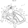
- FIG. 17 is a perspective view of a self-propelled toy 1' according to the second embodiment of the present invention
- FIG. 18 is a top view of the self-propelled toy 1' according to the second embodiment of the present invention.
- the self-propelled toy 1' has a substantially symmetrical shape about the centerline CL of vehicle width.
- the self-propelled toy 1' includes a vehicle body 2', wheels (front wheels 3 and rear wheels 4) connected to the vehicle body 2', a support arm 5 extending upward from the vehicle body 2', an imaging device 6 supported by the support arm 5, and an operating part 7 and charging port 8 provided at the vehicle body 2'.
- the vehicle body 2' includes, instead of the main cover 21, a front cover 21a forming the top part and the side parts of the self-propelled toy 1', two side covers forming the top part and the side parts of the self-propelled toy 1' (a right side cover 21b and a left side cover 21c), and a rear cover 21d forming the top part and the rear part of the self-propelled toy 1'.
- the outer shapes of these covers 21a, 21b, 21c, and 21d in the top view of the self-propelled toy 1' ( FIG. 18 ) are substantially the same as the outer shape of the main cover 21 shown in FIG. 2 .
- the vehicle body 2' includes a driving seat 26 at which a figurine 261 is provided.
- the driving seat 26 has a seat surface and a backrest.
- the front, rear, left, and right of the driving seat 26 are surrounded by the covers 21a, 21b, 21c and 21d, and the driving seat 26 is open above it.
- the figurine 261 has arms, legs, a body and a head, and is seated at the driving seat 26.
- the driving seat 26 is arranged between the front wheels 3 and rear wheels 4 in the front-rear direction. Further, in the vehicle width direction, the driving seat 26 is arranged at the insides of the front wheels 3 and rear wheels 4 and arranged in the region near the center. In particular, in the present embodiment, the driving seat 26 is arranged so that the centerline and the median plane of the figurine 261 match the centerline CL of vehicle width. Due to this, it is possible to keep the balance of weights of the left and right of the self-propelled toy 1 from deteriorating and in turn possible to keep the running performance of the self-propelled toy 1 from falling.
- the support arm 5 extends from the rear of the driving seat 26 to above the figurine 261 upward at a slant so that the imaging device 6 is arranged right above the head part of the figurine 261.
- the operating part 7 is provided at the top part of the right side cover 21b
- the charging port 8 is provided at the side part of the right side cover 21b
- the opening lid 20 forms the right side part of the vehicle body 2' together with the right side cover 21b.
- the positions of the support arm 5, the imaging device 6, the operating part 7, and the charging port 8 with respect to the vehicle body 2' and wheels 3, 4 are similar to the first embodiment.
- FIG. 19 is a perspective view of the self-propelled toy 1' showing the inside of the vehicle body 2'.
- FIG. 19 shows the self-propelled toy 1' when the front cover 21a, the side covers 21b, 21c, the rear cover 21d, and the driving seat 26 are detached.
- the vehicle body 2' includes a middle housing 27.
- the vehicle body 2' is comprised of the opening lid 20, the front cover 21a, the side covers 21b, 21c, the rear cover 21d, the main chassis 22, the drive part cover 23, the steering part cover 24, the bottom cover 25, the driving seat 26, and the middle housing 27.
- the middle housing 27 is arranged above the main chassis 22 and holds the driving seat 26.
- the driving seat 26 is attached to the top part of the middle housing 27.
- the driving seat 26 is fixed to the top part of the middle housing 27 by bolts 206.
- the self-propelled toy 1' in which the middle housing 27 is detached is similar to the self-propelled toy 1 in the first embodiment and is shown in FIG. 5 .
- the middle housing 27 is attached to the top part of the main chassis 22 so as to cover the steering part cover 24, the board 9, and the camera-use FPC 61 shown in FIG. 5 .
- the middle housing 27 is fixed by screws 207 to the top part of the main chassis 22.
- a grip part 270 comprised of the steering shaft 271 and the steering wheel 272 is attached to the middle housing 27.
- the steering shaft 271 extends from the middle housing 27.
- the steering wheel 272 is attached to the front end of the steering shaft 27 and is gripped by the figurine 261.
- the middle housing 27 may be omitted and the driving seat 26 may be attached to the top part of the main chassis 22.
- the grip part 270 is attached to the main chassis 22 or the driving seat 26.
- FIG. 20 is a left side cross-sectional view of the self-propelled toy 1' along the centerline CL of vehicle width.
- the driving seat 26 is arranged above the battery 12 and board 9 in the vertical direction and is arranged at the front from the drive member 10 and at the rear from the steering member 11 in the front-rear direction. Due to this, it is possible to efficiently utilize spaces in front of, behind and below the driving seat 26.
- the drive motor 101 is greatest in length in the vertical direction and the steering-use motor 111 is second longest in length in the vertical direction. For this reason, by arranging the drive motor 101 and the steering-use motor 111 in front of and behind the driving seat 26, the vehicle body 2 can be kept from becoming longer in length in the vertical direction. Further, the support arm 5 is connected to the vehicle body 2 right above the drive motor 101. By doing this, it is possible to effectively utilize the space behind the driving seat 26 and decrease the total length of the self-propelled toy 1'.
- the switch 91, the first antenna 92, the second antenna 93 and the wireless communication IC 94 overlap the driving seat 26 in the front-rear direction and are mounted on the top surface of the board 9 at the outside from the driving seat 26 in the vehicle width direction. Due to this, it is possible to effectively utilize the space at the outside of the driving seat 26.
- the camera-use FPC 61 is arranged right below the backrest of the driving seat 26. By utilizing the dead space below the backrest in this way, it is possible to lower the position of the seat surface of the driving seat 26 without increasing the total length of the self-propelled toy 1.
- the bottom cover 25 is fixed to the main chassis 22 through a spacer member arranged between the main chassis 22 and the bottom cover 25, and the stepped screws 13 shown in FIG. 12 are used as limiting members.
- the right side cover 21b functions as the spacer member, and the stepped screws 13 fasten the right side cover 21b to the main chassis 22 so that the right side cover 21b abuts against the main chassis 22, and limit movement of the bottom cover 25 in the vertical direction so that a clearance is formed between the bottom cover 25 and the right side cover 21b.
- the configuration and control of the self-propelled toy used in the third embodiment are basically the same as the configuration and control of the self-propelled toy according to the first embodiment except for the points explained below. Therefore, below, the third embodiment of the present invention will be explained centered on parts different from the first embodiment.
- FIG. 21 is a schematic view of the configuration of a game system 300 according to the third embodiment of the present invention.
- the game system 300 includes a self-propelled toy 1 and a remote control device 400.
- the remote control device 400 is separate from the self-propelled toy 1, and includes, for example, a control part such as a CPU, a storage part such as a memory, an operating part such as a steering wheel or stick, a display part such as a display, etc.
- the self-propelled toy 1 and the remote control device 400 can communicate with each other by Wi-Fi®, Bluetooth®, or other short distance wireless communication.
- the self-propelled toy 1 for example, sends state quantities of the self-propelled toy 1 detected by a sensor (IMU 97 etc.,) provided at the self-propelled toy 1 and images captured by the imaging device 6 to the remote control device 400.
- the remote control device 400 for example, sends control signals for controlling the self-propelled toy 1 to the self-propelled toy 1 to thereby remotely control the self-propelled toy 1.
- the self-propelled toys 1, 1' may be two-wheeled motorcycles, three-wheeled motorcycles or automobiles, six-wheeled or more automobiles, etc. That is, the number of wheels of the self-propelled toys 1, 1' may be other than four. Further, the self-propelled toys 1, 1' may be endless track types, so-called caterpillar® types, with belts wound around the wheels. Further, the wheels may be omitted and the self-propelled toys 1, 1' may be motorboats etc., able to run on the water.
- the steering member 11 may be omitted and the self-propelled toys 1, 1' may be configured to proceed straight or may be configured to run along a running course. Further, either of the first antenna 92 and the second antenna 93 may be omitted. Further, the first antenna 92, the second antenna 93, and the wireless communication IC 94 may be omitted. That is, the self-propelled toys 1, 1' need not have wireless communication function. In this case, for example, the image captured by the imaging device 6 is stored in a memory provided in the self-propelled toys 1, 1' and is taken out to the outside through the memory. Further, instead of the battery 12, a primary battery may be used and the charging port 8 may be omitted.
- the support arm 5 may be omitted and the imaging device 6 may be directly connected to the vehicle bodies 2, 2' (for example, the main cover 21, the front cover 21a, etc.). Further, the support arm 5 may be integral with the vehicle bodies 2, 2' (for example, the main cover 21, the rear cover 21d, etc.)
- the above-mentioned embodiments can be implemented in any combination.
- the self-propelled toy 1 of the first embodiment instead of the self-propelled toy 1 of the first embodiment, the self-propelled toy 1' of the second embodiment may be used.
- the self-propelled toy 1' of the second embodiment instead of the front cover 21a, the side covers 21b, 21c, and the rear cover 21d, the main cover 21 may be used, and the main cover 21 may be configured to cover the driving seat 26 and the figurine 261.
- the main cover 21 may be at least partially transparent or semitransparent so that the figurine 261 is visible from the outside.
Landscapes
- Engineering & Computer Science (AREA)
- Computer Networks & Wireless Communication (AREA)
- Multimedia (AREA)
- Signal Processing (AREA)
- Toys (AREA)
Abstract
Description
- The present invention relates to a self-propelled toy.
- Known in the past has been a self-propelled toy including an imaging device capturing an image of a front area (for example, Japanese Unexamined Patent Publication No.
2004-298538 - In view of the above, an object of the present invention is to improve the convenience, improve the durability, improve the running performance, etc., so as to improve the user friendliness of the self-propelled toy.
- The summary of the present disclosure is as follows.
- (1) A self-propelled toy including: a vehicle body, wheels connected to the vehicle body, a battery provided at the vehicle body, a motor using electric power stored in the battery to output drive power for running use, an imaging device connected to the vehicle body so as to capture an image of an area in front of the self-propelled toy, an operating part operated by a user so as to make the imaging device operate, and a charging port supplying electric power from an outside power source to the battery, wherein the operating part is provided at a top part of the vehicle body at one side from a centerline of vehicle width of the self-propelled toy, and the charging port is provided at a side part of the vehicle body at the same side as the operating part from the centerline of vehicle width.
- (2) The self-propelled toy described in above (1), wherein the wheels include at least one front wheel and at least one rear wheel, and the operating part and the charging port are arranged between the at least one front wheel and the at least one rear wheel.
- (3) The self-propelled toy described in above (1) or (2), wherein the charging port is arranged at an inside from the outermost part of the wheels in a vehicle width direction.
- (4) The self-propelled toy described in above (3), wherein the outermost part of the side part of the vehicle body at which the charging port is provided is positioned at an outside from the outermost part of the wheels in a vehicle width direction.
- (5) The self-propelled toy described in any one of above (1) to (4), wherein the wheels are respectively comprised of a tire and a tire wheel, the operating part is a button which is pressed downward, and the vehicle body and the wheels are configured so that a bottom surface of the vehicle body touches a running surface when a downward force causes the tire to be flattened.
- (6) The self-propelled toy described in any one of above (1) to (5), wherein the wheels are respectively comprised of a hollow tire and a tire wheel, the operating part is a button which is pressed downward, and the bottommost point of the tire wheel is positioned above a bottom surface of the vehicle body, and a distance in a vertical direction between the bottommost part of the tire wheel and the bottom surface of the vehicle body is equal to or greater than a thickness of the hollow tire.
- (7) The self-propelled toy described in any one of above (1) to (6), further including: a board on which a plurality of electronic components are mounted, wherein the vehicle body includes a main chassis, and the board is attached to a top part of the main chassis and the battery is attached to a bottom part of the main chassis.
- (8) The self-propelled toy described in above (7), wherein the board has extension parts overlapping the battery in a front-rear direction and extending to an outside from the battery in a vehicle width direction, and at least one electronic component among the plurality of electronic components is mounted on at least one bottom surface of the extension parts.
- (9) The self-propelled toy described in above (8), wherein a switch turned on and off by the operating part is mounted on one top surface of the extension parts.
- (10) The self-propelled toy described in above (8) or (9), wherein a recessed part for housing the battery is formed at a bottom part of the main chassis and a through hole is formed at a side wall of the recessed part, and a connector is mounted on one bottom surface of the extension parts, and wiring of the battery is connected to the connector through the through hole.
- (11) The self-propelled toy described in above 9, wherein the motor is a brushed motor, and the extension parts are positioned at a front from the motor, and at least one wireless communication antenna is mounted on at least one top surface of the extension parts at a front from the switch.
- (12) The self-propelled toy described in any one of above (1) to (6), further including: a board on which a plurality of electronic components are mounted, wherein the vehicle wheels include front wheels and rear wheels, the vehicle body includes a main chassis, the board is attached to a top part of the main chassis and has side regions extending to an outside from innermost parts of the front wheels and the rear wheels in a vehicle width direction between the front wheels and the rear wheels, and a switch turned on and off by the operating part is mounted on one top surface of the side regions.
- (13) The self-propelled toy described in above (12), wherein the motor is a brushed motor, and the side regions are positioned at a front from the motor, and at least one wireless communication antenna is mounted on at least one top surface of the side regions at a front from the switch.
- (14) The self-propelled toy described in any one of above (1) to (13), wherein the vehicle body includes a main chassis and a bottom cover attached to the main chassis and forming a bottom part of the vehicle body, and the self-propelled toy further includes a limiting member limiting movement of the bottom cover in a vertical direction so that a clearance is formed above the bottom cover.
- (15) The self-propelled toy described in above (14), wherein the vehicle body further includes a spacer member arranged between the main chassis and the bottom cover, and the limiting member is a stepped screw, fixes the spacer member to the main chassis so that the spacer member abuts against the main chassis, and limits movement of the bottom cover in a vertical direction so that a clearance is formed between the bottom cover and the spacer member.
- (16) The self-propelled toy described in any one of above (1) to (15), further including: a support arm extending upward from the vehicle body and connecting the imaging device to the vehicle body, and at least one light emitting diode provided at the support arm so as to be visible from an outside.
- (17) The self-propelled toy described in any one of above (1) to (16), further including: a board on which a plurality of electronic components are mounted, wherein the vehicle body includes a driving seat at which a figurine is provided, and the board is arranged below the driving seat, and a switch turned on and off by the operating part overlaps the driving seat in a front-rear direction and is mounted on the board at an outside from the driving seat in a vehicle width direction.
- (18) The self-propelled toy described in any one of above (1) to (17), further including: a support arm extending upward from the vehicle body and connecting the imaging device to the vehicle body, wherein the vehicle body includes a driving seat at which a figurine is provided, and the motor is arranged at a rear from the driving seat and the support arm is connected to the vehicle body right above the motor.
- (19) A game system including: the self-propelled toy described in any one of above (1) to (18), and a remote control device able to remotely control the self-propelled toy.
- According to the present invention, it is possible to improve the convenience, improve the durability, improve the running performance, etc., so as to improve the user friendliness of the self-propelled toy.
-
-
FIG. 1 is a perspective view of a self-propelled toy according to a first embodiment of the present invention. -
FIG. 2 is a top view of the self-propelled toy according to the first embodiment of the present invention. -
FIG. 3 is a disassembled perspective view of the imaging device of the self-propelled toy. -
FIG. 4 is a disassembled perspective view of the imaging device of the self-propelled toy. -
FIG. 5 is a perspective view of the self-propelled toy showing the inside of a vehicle body. -
FIG. 6 is a perspective view of the self-propelled toy showing the inside of the vehicle body. -
FIG. 7 is a left side cross-sectional view of the self-propelled toy along a centerline of the vehicle width. -
FIG. 8 is a disassembled perspective view of a drive part cover and rear wheels of the self-propelled toy. -
FIG. 9 is a view showing a drive member inside the drive part cover ofFIG. 8 . -
FIG. 10 is a partial perspective view of the self-propelled toy showing the inside of the vehicle body. -
FIG. 11 is a bottom view of the wheels and board of the self-propelled toy. -
FIG. 12 is a bottom view of the self-propelled toy. -
FIG. 13 is a bottom view of the self-propelled toy showing a battery. -
FIG. 14 is a perspective view of the self-propelled toy showing a bottom part of a main chassis. -
FIG. 15 is an enlarged side cross-sectional view of the self-propelled toy showing an area around a stepped screw. -
FIG. 16 is a right side view of the self-propelled toy set horizontally on a running surface. -
FIG. 17 is a perspective view of a self-propelled toy according to a second embodiment of the present invention. -
FIG. 18 is a top view of the self-propelled toy according to the second embodiment of the present invention. -
FIG. 19 is a perspective view of the self-propelled toy showing the inside of the vehicle body. -
FIG. 20 is a left side cross-sectional view of the self-propelled toy along the centerline of the vehicle width. -
FIG. 21 is a schematic view of the configuration of a game system according to a third embodiment of the present invention. - Below, referring to the drawings, embodiments of the present invention will be explained in detail. Note that, in the following explanation, similar component elements are assigned the same reference numerals.
- Below, referring to
FIG. 1 to FIG. 16 , a first embodiment of the present invention will be explained. -
FIG. 1 is a perspective view of a self-propelled toy 1 according to the first embodiment of the present invention, andFIG. 2 is a top view of the self-propelledtoy 1 according to the first embodiment of the present invention. The self-propelledtoy 1 has a substantially symmetrical shape about a centerline CL of vehicle width. As shown inFIG. 1 , the self-propelledtoy 1 includes avehicle body 2, wheels (front wheels 3 and rear wheels 4) connected to thevehicle body 2, asupport arm 5 extending upward from thevehicle body 2, animaging device 6 supported by thesupport arm 5, and anoperating part 7 andcharging port 8 provided at thevehicle body 2. - The self-
propelled toy 1 has an appearance resembling that of an actual vehicle while has a size smaller than an actual vehicle. The self-propelledtoy 1 is also called a toy vehicle. In the present embodiment, the self-propelledtoy 1 has an appearance resembling an automobile and can run on the ground. For this reason, the self-propelledtoy 1 includes, as wheels, two front wheels 3 (rightfront wheel 3a and leftfront wheel 3b) and two rear wheels 4 (rightrear wheel 4a and leftrear wheel 4b). Thefront wheels 3 are respectively comprised of afront tire 31 and afront tire wheel 32, while therear wheels 4 are respectively comprised of arear tire 41 and arear tire wheel 42. The diameters of thefront tire 31 and thefront tire wheel 32 are respectively equal to therear tire 41 and therear tire wheel 42, and the diameter of thefront wheel 3 is equal to the diameter of therear wheel 4. - Further, the widths of the
front tire 31 and thefront tire wheel 32 are respectively smaller than the widths of therear tire 41 andrear tire wheel 42, and the width of thefront wheel 3 is shorter than the width of therear wheel 4. In the present embodiment, the innermost parts of therear wheels 4 in the vehicle width direction are positioned at the insides from the innermost parts of thefront wheels 3, and the outermost parts of therear wheels 4 are positioned at the outsides from the outermost parts of thefront wheels 3. - The
vehicle body 2 houses components for driving the self-propelledtoy 1 and components for controlling the self-propelledtoy 1 and protects these components from impact from the outside. - As shown in
FIG. 2 , thevehicle body 2 extends in the front-rear direction from the front from thefront wheels 3 to the rear from therear wheels 4 and extends in the vehicle width direction to the outsides from thefront wheels 3 andrear wheels 4. For this reason, thevehicle body 2 can protect thefront wheels 3 andrear wheels 4 from impact from the front, rear, left, and right. Further, the front end part of thevehicle body 2 positioned at the front from thefront wheels 3 extends to the outside from the innermost parts of thefront wheels 3 in the vehicle width direction. Due to this, the front end part of thevehicle body 2 functions as a bumper and can effectively protect the self-propelledtoy 1 from impact from the front. - As shown in
FIG. 1 andFIG. 2 , thevehicle body 2 includes amain cover 21 forming the top part, front part, side parts, and rear part of thevehicle body 2. Themain cover 21 covers the components housed in thevehicle body 2 so that these components cannot be seen from the outside. Themain cover 21 functions as the exterior of the self-propelledtoy 1 and defines the outer shape of the self-propelledtoy 1. - Further, the
vehicle body 2 includes anopening lid 20 covering a chargingport 8. The openinglid 20 is attached to themain cover 21 to be able to open and close. The openinglid 20 together with themain cover 21 forms one side part of the vehicle body 2 (in the present embodiment, the right side part of the vehicle body 2).FIG. 1 shows the self-propelledtoy 1 when the openinglid 20 is opened. When opened, the openinglid 20 exposes the chargingport 8 to the outside, while when closed, it conceals the chargingport 8 from the outside. In the present embodiment, the openinglid 20 is configured to open and close in the vertical direction in a sliding manner. Note that, the openinglid 20 may be configured to open and close in another opening and closing manner (for example, open and close in a hinge manner or open and close to left and right in a sliding manner). - The charging
port 8 is used for charging a battery provided at thevehicle body 2 and, for example, is configured as a USB connector. When the battery is not being charged, the chargingport 8 is covered by the openinglid 20 so that foreign matter can be kept from entering the chargingport 8. Further, the openinglid 20 can protect the chargingport 8 from impact from the outside. Note that details of the battery will be explained later. - In the present embodiment, as will be understood from
FIG. 1 , the chargingport 8 is provided at the side part of thevehicle body 2 at one side from the centerline CL of vehicle width of the self-propelledtoy 1, and theopening lid 20 forms the side part of thevehicle body 2 at the same side as the chargingport 8 from the centerline CL of vehicle width. Due to this, a user can easily access the chargingport 8 from the side of the self-propelledtoy 1 through the openinglid 20. Further, when connecting the chargingport 8 of the self-propelledtoy 1 set horizontally to an outside power source, a connection cord connecting the chargingport 8 to the outside power source can be kept from entangling with thewheels port 8 is provided at the right side part of thevehicle body 2, but the chargingport 8 may be provided at the left side part of thevehicle body 2. - Below, the configuration for using the self-propelled
toy 1 to capture an image will be explained. Theimaging device 6 shown inFIG. 1 , for example, is a CMOS (complementary metal oxide semiconductor) camera or a CCD (charge coupled device) camera and is connected to thevehicle body 2 so as to capture an image of the area in front of the self-propelledtoy 1. - In the present embodiment, the
imaging device 6 is connected to thevehicle body 2 through thesupport arm 5. Thesupport arm 5 is connected to thevehicle body 2 between the rightrear wheel 4a and the leftrear wheel 4b and extends toward the front upward at a slant. Theimaging device 6 is housed in thesupport arm 5 and is arranged at a front end part of thesupport arm 5. As a result, theimaging device 6 is positioned at the topmost part of the self-propelledtoy 1 and is positioned in front of therear wheels 4. The front end of thesupport arm 5 is closed, and theimaging device 6 captures an image of the front area through a transparent or semitransparent part of thesupport arm 5. - Further, as shown in
FIG. 2 , thesupport arm 5 andimaging device 6 are arranged at a region near the center in the vehicle width direction (a center region among regions when self-propelledtoy 1 is divided into three equal parts in vehicle width direction). Due to this, it is possible to keep the balance of weights of the left and right of the self-propelledtoy 1 from deteriorating and in turn possible to keep the running performance of the self-propelledtoy 1 from falling. - In the present embodiment, the
support arm 5 andimaging device 6 are arranged on the centerline CL of vehicle width. Specifically, thesupport arm 5 andimaging device 6 are arranged so that the center of theimaging device 6 is positioned on the centerline CL of vehicle width. Further, thesupport arm 5 andimaging device 6 are arranged so that when the self-propelledtoy 1 is set horizontal, the optical axis of theimaging device 6 slants downward with respect to the horizontal direction (for example, by 5° to 15°). Due to such placement, in the present embodiment, the front part of thevehicle body 2, the rightfront wheels 3a, the leftfront wheels 3b, and the front area of the self-propelledtoy 1 are contained in the angle of view of theimaging device 6, and theimaging device 6 captures these. -
FIG. 3 and FIG. 4 are disassembled perspective views of theimaging device 6 of the self-propelledtoy 1.FIG. 3 shows the front part of theimaging device 6 and the range of capture of theimaging device 6, whileFIG. 4 shows the rear part of theimaging device 6. As shown inFIG. 3 and FIG. 4 , a camera-use FPC 61 is connected to theimaging device 6. The camera-use FPC 61 extends inside thesupport arm 5 and is connected to a later explained board. - Further, as shown in
FIG. 4 , the self-propelledtoy 1 includes a first light emitting diode (LED) 62 emitting blue light and a second light emitting diode (LED) 63 emitting red light. Thefirst LED 62 and thesecond LED 63 are provided at thesupport arm 5 so as to be visible from the outside. For example, thefirst LED 62 is turned on when theimaging device 6 is being operated, while thesecond LED 63 is turned on when the battery is being charged. Due to this, a user can easily grasp the state of the self-propelledtoy 1 from a separate location. - In the present embodiment, the
first LED 62 and thesecond LED 63 are mounted on the camera-use FPC 61. Therefore, as shown inFIG. 2 , thefirst LED 62 and thesecond LED 63 are arranged inside thesupport arm 5 and are visible from above and behind the self-propelledtoy 1 through a transparent or semitransparent part of thesupport arm 5. As explained above, theimaging device 6, thefirst LED 62, and thesecond LED 63 are arranged inside thesupport arm 5. Due to this, it is possible to keep the user from mistakenly touching these and in turn possible to improve their durabilities. - Note that, the configuration and functions of the LEDs provided at the
support arm 5 are not limited to the above. For example, thefirst LED 62 and thesecond LED 63 may emit different color light. Further, one of thefirst LED 62 and thesecond LED 63 may be omitted or thefirst LED 62 and thesecond LED 63 may be made integral. Further, thefirst LED 62 and thesecond LED 63 may be connected to the board by wiring (FPC or lead wires) different from the camera-use FPC 61. Further, there may be three or more LEDs. - The user switches the operating state of the
imaging device 6 using theoperating part 7 shown inFIG. 1 andFIG. 2 . That is, the operatingpart 7 is operated by the user for making theimaging device 6 operate. For example, when theimaging device 6 is capturing a still image, the user operates the operatingpart 7 to determine the shutter timing. Further, when theimaging device 6 captures a moving image, the user operates the operatingpart 7 to make theimaging device 6 start up. In this case, the operatingpart 7 is operated to turn on the power of the self-propelledtoy 1, and when the operatingpart 7 is operated or after a predetermined time (for example, several seconds to tens of seconds) after theoperating part 7 is operated, image capture by theimaging device 6 is started. Further, the operatingpart 7 is operated to turn on the power of the self-propelledtoy 1, and then image capture by theimaging device 6 may be started based on instruction from an outside apparatus. That is, operation of the operatingpart 7 may be one of the conditions for start of image capture. In this way, the operatingpart 7 is operated by the user to directly or indirectly make theimaging device 6 operate. Further, the operatingpart 7 may also be operated by the user when the user turnes off the power of the self-propelledtoy 1. - At the time of use, the self-propelled
toy 1 is basically set on the floor or other running surface. Therefore, the user usually sees the top part of the self-propelledtoy 1. Accordingly, in the present embodiment, the operatingpart 7 is provided on the top part of thevehicle body 2. By doing this, the user frequently sees the operatingpart 7 and in turn can easily grasp the position of the operatingpart 7. Further, the user can easily access theoperating part 7 from above thevehicle body 2. - Further, as shown in
FIG. 1 andFIG. 2 , the operatingpart 7 is provided at the top part of thevehicle body 2 at one side from the centerline CL of vehicle width. Due to this, when the user is holding the self-propelledtoy 1 substantially horizontally by his or her two hands to capture an image of the area in front of the self-propelledtoy 1, operation of the operatingpart 7 by one hand becomes easy. In the present embodiment, the operatingpart 7 is provided at the top right part of thevehicle body 2, specifically at the top right part of themain cover 21. In this case, when using the self-propelledtoy 1 to capture an image of an object in front of it, the user can operate theoperating part 7 by his or her right hand, while when using the self-propelledtoy 1 to capture an image of the user himself or herself, he or she can operate theoperating part 7 by his or her left hand. Note that, the operatingpart 7 may be provided at the top left part of thevehicle body 2. - The operating
part 7 is, for example, configured as an operating button pressed downward. The operatingpart 7 extends downward from the top surface of thevehicle body 2 and moves in the vertical direction by operation by the user. Further, the operatingpart 7 is housed in thevehicle body 2 so that the top surface of the operatingpart 7 becomes flush with the top surface of the vehicle body 2 (in the present embodiment, the top surface of the main cover 21). Due to this, it is possible to reduce the incidence of the operatingpart 7 being mistakenly operated when the self-propelledtoy 1 flips over or is struck without causing a drop in the ease of operation of the operatingpart 7. - Further, as shown in
FIG. 1 , the chargingport 8 is provided at the side part of thevehicle body 2 at the same side as the operatingpart 7 from the centerline CL of vehicle width. By doing this, even if the chargingport 8 is provided at the side part of thevehicle body 2, the user can easily grasp the position of the chargingport 8 using theoperating part 7 as a locator. This advantage becomes particularly remarkable if, like in the present embodiment, the chargingport 8 is covered by the openinglid 20. Further, if the user finds by operation of the operatingpart 7 that the battery does not have sufficient electric power, for example, if when operating the operatingpart 7 the self-propelled toy 1 (specifically theimaging device 6 etc.) does not react, it is possible to quickly access the chargingport 8 at the same side as the operatingpart 7 to start charging the battery. Therefore, due to the arrangement of the above-mentionedoperating part 7 and chargingport 8, the user friendliness of the self-propelledtoy 1 can be improved. - Further, the operating
part 7 and chargingport 8 are arranged between thefront wheels 3 and therear wheels 4. For this reason, thefront wheels 3 can protect theoperating part 7 and chargingport 8 from impact from the front, while therear wheels 4 can protect theoperating part 7 and chargingport 8 from impact from the rear. -
FIG. 5 is a perspective view of the self-propelledtoy 1 showing the inside of thevehicle body 2.FIG. 5 shows the self-propelledtoy 1 when themain cover 21 is detached. As shown inFIG. 5 , thevehicle body 2 includes amain chassis 22. Themain chassis 22 extends in the front-rear direction from the front of thefront wheels 3 to the rear of therear wheels 4 and holds the later explained main components of the self-propelledtoy 1. - As shown in
FIG. 5 , the self-propelledtoy 1 includes aboard 9 on which a plurality of electronic components are mounted. Theboard 9 is attached to the top part of themain chassis 22, and themain chassis 22 holds theboard 9. In the present embodiment, theboard 9 is fixed byscrews 201 to the top part of themain chassis 22. Further, as shown inFIG. 5 , theboard 9 extends between thefront wheels 3 and therear wheels 4 and extends in the vehicle width direction from the rightfront wheel 3a and the rightrear wheel 4a to the leftfront wheel 3b and the leftrear wheel 4b. - The above-mentioned
support arm 5 is connected to themain chassis 22 at the rear from theboard 9. Specifically, thesupport arm 5 is connected to themain chassis 22 between the rightrear wheel 4a and the leftrear wheel 4b. In the present embodiment, thesupport arm 5 has afastening part 51 arranged inside themain cover 21 and is fixed through thefastening part 51 byscrews 202 to the top part of themain chassis 22. -
FIG. 6 is a perspective view of the self-propelledtoy 1 showing the inside of thevehicle body 2.FIG. 6 shows the self-propelledtoy 1 ofFIG. 5 when thesupport arm 5 is detached from the self-propelledtoy 1. Thevehicle body 2 includes adrive part cover 23 covering a later explained drive member and asteering part cover 24 covering a later explained steering member. - The
drive part cover 23 is arranged between thesupport arm 5 and themain chassis 22 in the vertical direction and is attached to the top part of themain chassis 22 at the rear from theboard 9. Specifically, thedrive part cover 23 is fixed between the rightrear wheel 4a and the leftrear wheel 4b byscrews 203 to the top part of themain chassis 22. Thesteering part cover 24 is attached to the top part of themain chassis 22 at the front from theboard 9. Specifically, thesteering part cover 24 is fixed between the rightfront wheel 3a and the leftfront wheel 3b byscrews 204 to the top part of themain chassis 22. -
FIG. 7 is a left side cross-sectional view of the self-propelledtoy 1 along the centerline CL of vehicle width. As shown inFIG. 7 , the self-propelledtoy 1 includes adrive member 10, a steeringmember 11, and abattery 12. Thedrive member 10, the steeringmember 11, and thebattery 12 are provided at thevehicle body 2. - The
drive member 10 uses electric power stored in thebattery 12 to drive therear wheels 4. The steeringmember 11 uses the electric power stored in thebattery 12 to steer thefront wheels 3. Thebattery 12 is a secondary battery able to be charged by an outside power source and, for example, is a lithium ion battery, nickel-hydrogen battery, etc. -
FIG. 8 is a disassembled perspective view of thedrive part cover 23 and therear wheels 4 of the self-propelledtoy 1, whileFIG. 9 is a view showing thedrive member 10 in thedrive part cover 23 ofFIG. 8 . As shown inFIG. 9 , thedrive member 10 includes adrive motor 101,pinion gear 102,counter gear 103,spur gear 104, andwheel shaft 105. - The
drive motor 101 uses electric power stored in thebattery 12 to output drive power for running use (driving power). Thedrive motor 101 is a DC motor, for example, a brushed motor or a brushless motor. Thepinion gear 102 is connected to thedrive motor 101, thespur gear 104 is connected to thewheel shaft 105, and thecounter gear 103 is arranged between thepinion gear 102 and thespur gear 104. Thepinion gear 102, thecounter gear 103, and thespur gear 104 convert rotation of thedrive motor 101 to rotation of thewheel shaft 105. Therear wheels 4 are connected to the both ends of thewheel shaft 105 and rotate together with thewheel shaft 105. Therefore, thedrive member 10 can drive therear wheels 4. - As will be understood from
FIG. 8 andFIG. 9 , thedrive motor 101, thepinion gear 102, thecounter gear 103, and thespur gear 104 are housed in thedrive part cover 23, while thewheel shaft 105 is connected to thedrive part cover 23. Therefore, thedrive member 10 is held by thedrive part cover 23 and is positioned by thedrive part cover 23. That is, since, in the present embodiment, thedrive member 10 is positioned by a single component (the drive part cover 23), it is possible to raise the positioning precision among components of thedrive member 10. - The
drive member 10 and therear wheels 4 are connected through thedrive part cover 23 to themain chassis 22. As a result, themain chassis 22 holds thedrive member 10 and therear wheels 4 through thedrive part cover 23. At this time, thedrive motor 101 is arranged in a region near the center in the vehicle width direction. Due to this, it is possible to keep the balance of weights of the left and right of the self-propelledtoy 1 from deteriorating and in turn possible to keep the running performance of the self-propelledtoy 1 from falling. -
FIG. 10 is a partial perspective view of the self-propelledtoy 1 showing the inside of thevehicle body 2.FIG. 10 shows the front part of the self-propelledtoy 1 when themain cover 21 and thesteering part cover 24 are detached. As shown inFIG. 7 andFIG. 10 , the steeringmember 11 includes a steering-use motor 111, apinion gear 112, acrown gear 113, asector gear 114, apotentiometer 115, atie rod 116, and knucklearms 117. - The steering-
use motor 111, thepinion gear 112, thecrown gear 113, thesector gear 114, and thepotentiometer 115 are housed in themain chassis 22 and held by themain chassis 22. Further, thetie rod 116, theknuckle arms 117, and thefront wheels 3 are connected to themain chassis 22 so that thefront wheels 3 can be turned to the left and right. Therefore, themain chassis 22 holds the steeringmember 11 and thefront wheels 3. - The steering-
use motor 111 uses electric power stored in thebattery 12 to output drive power for steering use. The steering-use motor 111 is a DC motor, for example, a brushed motor or a brushless motor. As shown inFIG. 10 , the steering-use motor 111 is arranged in a region near the center in the vehicle width direction. In particular, in the present embodiment, the steering-use motor 111 is arranged so that its axis matches the centerline CL of vehicle width. Due to this, it is possible to keep the balance of weights of the left and right of the self-propelledtoy 1 from deteriorating and in turn possible to keep the running performance of the self-propelledtoy 1 from falling. - The
pinion gear 112 is connected to the steering-use motor 111, thesector gear 114 is connected to thetie rod 116, and thecrown gear 113 is arranged between thepinion gear 112 and thesector gear 114. Thepinion gear 112, thecrown gear 113, and thesector gear 114 convert rotation of the steering-use motor 111 to linear motion of thetie rod 116. Due to linear motion of thetie rod 116, theknuckle arms 117 swing back and forth and the orientation of thefront wheels 3 connected to theknuckle arms 117 changes to the left and right. Therefore, the steeringmember 11 can steer thefront wheels 3. - As shown in
FIG. 7 , thepotentiometer 115 is arranged below thesector gear 114 and detects a rotational angle of thesector gear 114. The steering-use motor 111 is controlled based on the output of thepotentiometer 115 so that the steering angle of thefront wheels 3 becomes the target value. Note that, instead of the steering-use motor 111, thepotentiometer 115, etc., a servo motor may be used. - Further, as shown in
FIG. 7 , thedrive motor 101 is arranged at the rear from theboard 9 and thebattery 12, specifically is arranged between the rightrear wheel 4a and the leftrear wheel 4b. On the other hand, the steering-use motor 111 is arranged at the front from theboard 9 and thebattery 12, specifically is arranged in the front of thefront wheels 3. Among the components held by the main chassis 22 (theboard 9, the components on theboard 9, thebattery 12, the components of thedrive member 10, and the components of the steering member 11), the length of thedrive motor 101 in the vertical direction is the maximum, and the length of the steering-use motor 111 in the vertical direction is the second most longest. For this reason, it is possible to arrange thedrive motor 101 and the steering-use motor 111 in front of and behind theboard 9 and thebattery 12, and thereby keep the height of thevehicle body 2 from becoming greater. - Next, the positional relationship between the
board 9 and thebattery 12 will be explained in detail.FIG. 11 is a bottom view of thewheels board 9 of the self-propelledtoy 1.FIG. 11 shows thewheels board 9 when viewing the self-propelledtoy 1 from the bottom. In order to show the positional relationship with theboard 9, thebattery 12 positioned below theboard 9 is shown by broken lines. - In the present embodiment, the
board 9 and thebattery 12 are arranged so as to at least partially overlap in a horizontal plane (plane shown inFIG. 11 ). In other words, theboard 9 and thebattery 12 are arranged so as to at least partially overlap in a top view and a bottom view of the self-propelledtoy 1. By doing this, theboard 9 and thebattery 12 can be reduced in areas occupied compared to when arranging theboard 9 andbattery 12 side by side on the same plane. - As shown in
FIG. 11 , the length of theboard 9 in the longer direction becomes longer than the length of thebattery 12 in the shorter direction, while the length of thebattery 12 in the longer direction is longer than the length of theboard 9 in the shorter direction. Further, as will be understood fromFIG. 11 , the area of theboard 9 is larger than the area of thebattery 12 in a horizontal plane. Under these conditions, in the present embodiment, theboard 9 and thebattery 12 are arranged so as to perpendicularly intersect in the horizontal plane. In this case, compared to when arranging theboard 9 and thebattery 12 so that thebattery 12 fits inside theboard 9 in the horizontal plane, the areas occupied by theboard 9 and thebattery 12 become slightly larger, but the area of theboard 9 at the outside of thebattery 12 can be made larger. - Furthermore, in the present embodiment, the perpendicularly arranged
board 9 andbattery 12 are arranged so that the longer direction of theboard 9 matches the vehicle width direction. As will be understood fromFIG. 11 , the length of theboard 9 in the longer direction is longer than the length of thebattery 12 in the longer direction. For this reason, compared to when arranging theboard 9 and thebattery 12 so that the longer direction of theboard 9 matches the front-rear direction, it is possible to reduce the length of theboard 9 and thebattery 12 in the front-rear direction. Therefore, if arranging thedrive member 10 and the steeringmember 11 in front of and behind theboard 9 and thebattery 12, it is possible to reduce the length of the self-propelledtoy 1 in the front-rear direction and in turn improve the turning performance of the self-propelledtoy 1. - Further, as shown in
FIG. 11 , thebattery 12 is arranged in a region near the center in the vehicle width direction. In particular, in the present embodiment, thebattery 12 is arranged so that the centerline matches the centerline CL of vehicle width. Due to this, it is possible to keep the balance of weights of the left and right of the self-propelledtoy 1 from deteriorating and in turn possible to keep the running performance of the self-propelledtoy 1 from falling. - Below, the main electronic components mounted on the
board 9 will be explained. First, referring toFIG. 5 andFIG. 6 , the electronic components on the top surface of theboard 9 will be explained. As shown inFIG. 5 andFIG. 6 , on the top surface of theboard 9, aswitch 91 turned on and off by the operatingpart 7, afirst antenna 92 and asecond antenna 93 for wireless communication, awireless communication IC 94 covered by a shield, and a camera-use connector 95 are mounted. - As shown in
FIG. 5 andFIG. 6 , theboard 9 has two side regions (aright side region 90a and aleft side region 90b) extending to the outside from the innermost parts of thefront wheels 3 andrear wheels 4 in the vehicle width direction. Theswitch 91 and thefirst antenna 92 are mounted on the top surface of one side region of the board 9 (in the present embodiment, theright side region 90a), while thesecond antenna 93 and thewireless communication IC 94 are mounted on the top surface of the other side region of the board 9 (in the present embodiment, theleft side region 90b). By mounting these electronic components on the side regions of theboard 9, it is possible to effectively utilize the space between thefront wheels 3 and therear wheels 4. - The
switch 91 is arranged right below the above-mentionedoperating part 7 and is turned on and off by the operatingpart 7. In the present embodiment, theswitch 91 is turned on and off when the operatingpart 7 moves downward to push down theswitch 91. When theswitch 91 is turned on by the operatingpart 7, as explained above, theimaging device 6 is directly or indirectly operated. - Note that, in the present embodiment, the operating
part 7 and theswitch 91 are separate members, but theoperating part 7 and theswitch 91 may be integral. In this case, the operatingpart 7 and theswitch 91 are, for example, configured as a pushbutton switch, a slide switch, a toggle switch, a rocker switch, etc. - The
first antenna 92 and thesecond antenna 93 for wireless communication are configured in the same way and respectively send and receive electric waves. Thefirst antenna 92, thesecond antenna 93, and thewireless communication IC 94 are configured so as to send data to an outside apparatus and receive data from the outside apparatus. For example, thefirst antenna 92, thesecond antenna 93, and thewireless communication IC 94 receive control signals for controlling the self-propelledtoy 1 from the outside apparatus and send images captured by theimaging device 6 to the outside apparatus. That is, in the present embodiment, the self-propelledtoy 1 is a so-called radio-controlled toy vehicle. - Usually, while running, the self-propelled
toy 1 sends data toward the outside apparatus above the self-propelledtoy 1 and receives data from the outside apparatus above the self-propelledtoy 1. For this reason, as explained above, it is possible to raise the communication strength by mounting thefirst antenna 92 and thesecond antenna 93 on the top surface of theboard 9. - Further, in the present embodiment, as shown in
FIG. 6 , thefirst antenna 92 and thesecond antenna 93 are arranged at the both end parts of theboard 9 in the vehicle width direction and are mounted so that axes of the longer directions of thefirst antenna 92 and thesecond antenna 93 perpendicularly intersect, whereby it is possible to keep the communication strength from falling along with change of the relative position of the self-propelledtoy 1 and outside apparatus. - Further, the
first antenna 92 and thesecond antenna 93 are mounted at the front end part of theboard 9. Therefore, thefirst antenna 92 is mounted on the top surface of theright side region 90a of theboard 9 at the front from theswitch 91, while thesecond antenna 93 is mounted on the top surface of theleft side region 90b of theboard 9 at the front from thewireless communication IC 94. By doing this, it is possible to increase the distance between thefirst antenna 92 and thesecond antenna 93 and thedrive motor 101 arranged at the rear from theboard 9 while arranging a plurality of electronic components at the same side region. As a result, the noise generated from thedrive motor 101 can be kept from interfering with wireless communication by thefirst antenna 92 and thesecond antenna 93. This advantage is particularly remarkable when thedrive motor 101 is a brushed motor with large noise. - As shown in
FIG. 5 , a camera-use FPC 61 is connected to the camera-use connector 95. The camera-use FPC 61 is connected to the camera-use connector 95 along the top of thefastening part 51 from the inside of thesupport arm 5. In the present embodiment, the camera-use connector 95 is mounted on the rear end part of theboard 9 in the region near the center in the vehicle width direction and is positioned on the centerline CL of vehicle width. Theimaging device 6, thefirst LED 62, and thesecond LED 63 are electrically connected through the camera-use FPC 61 to theboard 9 and are supplied with electric power from thebattery 12. - Further, as shown in
FIG. 6 , wiring 301 (two lead wires) of thedrive motor 101 is connected to the rear end part of the top surface of theboard 9, while wiring 302 (two lead wires) of the steering-use motor 111 and wiring 303 (three lead wires) of thepotentiometer 115 are respectively connected to the front end part of the top surface of theboard 9. Thedrive motor 101, the steering-use motor 111, and thepotentiometer 115 are electrically connected through the wiring to theboard 9 and are supplied with electric power from thebattery 12. - Next, referring to
FIG. 11 , the electronic components on the bottom surface of theboard 9 will be explained. As shown inFIG. 11 , the chargingport 8, acontrol device 96 covered by a shield, an inertial measurement unit (IMU) 97, and a battery-use connector 98 are mounted on the bottom surface of theboard 9. - The
board 9 overlaps thebattery 12 in the front-rear direction and has extension parts (aright extension part 100a and aleft extension part 100b) extending to the outside from thebattery 12 in the vehicle width direction. The chargingport 8 and the battery-use connector 98 are mounted on the bottom surface of one of the extension parts (in the present embodiment, theright extension part 100a). Due to this, the space at the outside of the battery can be effectively utilized. - As will be understood from
FIG. 11 , theextension parts side regions front wheels 3 andrear wheels 4 in the vehicle width direction, and the chargingport 8 is mounted on theside region 90a. Similarly, theswitch 91, thefirst antenna 92, thesecond antenna 93, and thewireless communication IC 94 arranged at the top surface of theboard 9 shown inFIG. 5 andFIG. 6 are also mounted on theside regions front wheels 3 andrear wheels 4. - The charging
port 8, as explained above, is used for charging thebattery 12 and supplies electric power from an outside power source to thebattery 12. As shown inFIG. 11 , the chargingport 8 is arranged at the inside from the outermost parts of the wheels in the vehicle width direction (in the present embodiment, the outermost parts of the rear wheels 4). Due to this, the wheels can protect the chargingport 8 from impact from the sides. Further, in the present embodiment, as will be understood fromFIG. 2 , the outermost part of the side part of thevehicle body 2 at which the chargingport 8 is provided (in the present embodiment, the openinglid 20 and the main cover 21) is positioned at the outside from the outermost part of the wheel in the vehicle width direction. For this reason, thevehicle body 2 can also protect the chargingport 8 from impact from the side. Note that, the outermost parts of thefront wheels 3 may be arranged at the outsides from the outermost parts of therear wheels 4 and the chargingport 8 may be arranged at the inside from the outermost parts of thefront wheels 3 in the vehicle width direction. Further, the chargingport 8 may be arranged at the inside from the outermost parts of thefront wheels 3 and the outermost parts of therear wheels 4 in the vehicle width direction. - The
control device 96 has a CPU etc., and performs various control operations of the self-propelledtoy 1. Thecontrol device 96 is, for example, configured as an SOC (System on Chip) and is electrically connected to other components on theboard 9. As shown inFIG. 11 , thecontrol device 96 is arranged at a region near the center of the vehicle width direction. Specifically, it is arranged on the centerline CL of vehicle width. By doing this, it is possible to dissipate heat generated at thecontrol device 96 to the surrounding parts of theboard 9 and improve the heat radiating performance of the self-propelledtoy 1. - The
IMU 97 includes a three-axis acceleration sensor and a three-axis gyro sensor (angular velocity sensor) and functions as a six-axis sensor detecting the acceleration in three axial directions and angular velocity in three axial directions. For example, thecontrol device 96 controls the posture of the self-propelledtoy 1 based on the output of theIMU 97. As shown inFIG. 11 , theIMU 97 is arranged in a region near the center in the vehicle width direction, specifically, is arranged on the centerline CL of vehicle width. Due to this, it is possible to reduce the effect due to the left-right difference in operation of the self-propelledtoy 1. Further, in the present embodiment, theIMU 97 is arranged at the front from the chargingport 8, thecontrol device 96, and the battery-use connector 98. - Wiring of the battery 12 (for example lead wires) is connected to the battery-
use connector 98. The electric power stored in thebattery 12 is connected through the battery-use connector 98 to theboard 9. As shown inFIG. 11 , the battery-use connector 98 is arranged at the front from the chargingport 8 and thecontrol device 96 and is arranged at the inside from the chargingport 8 in the vehicle width direction. - Further, the battery-
use connector 98 has the greatest height (thickness) among the electronic components mounted on the bottom surface of theboard 9. Therefore, in the present embodiment, the electronic components mounted on theextension parts board 9 are positioned the lowest among the electronic components mounted on the bottom surface of theboard 9. For this reason, if, like in the present embodiment, theboard 9 is arranged above thebattery 12, it is possible to reduce the length in the vertical direction of theboard 9 on which the electronic components are mounted and thebattery 12. Note that, other electronic components arranged at theextension parts -
FIG. 12 is a bottom view of the self-propelledtoy 1. As shown inFIG. 12 , thevehicle body 2 includes abottom cover 25. In the present embodiment, thevehicle body 2 is comprised of the openinglid 20, themain cover 21, themain chassis 22, thedrive part cover 23, thesteering part cover 24, and thebottom cover 25. -
FIG. 13 is a bottom view of the self-propelledtoy 1 showing thebattery 12.FIG. 13 shows the self-propelledtoy 1 when thebottom cover 25 is detached. Thebottom cover 25 extends in the front-rear direction from the front from thefront wheels 3 to therear wheels 4 and covers thebattery 12 so that thebattery 12 cannot be seen from the outside. Thebottom cover 25 is attached to themain chassis 22, and thebottom cover 25 and themain chassis 22 form the bottom part (bottom surface) of thevehicle body 2. Further, the flat bottom surface of thebottom cover 25 forms the bottom surface of thevehicle body 2. - As explained above, the
board 9 is attached to the top part of themain chassis 22, while as will be understood fromFIG. 7 andFIG. 13 , thebattery 12 is attached to the bottom part of themain chassis 22. By doing this, it is possible to effectively utilize the spaces above and below themain chassis 22. Further, by arranging thebattery 12, which is the heaviest component, near the bottom part of thevehicle body 2, it is possible to lower the center of gravity of the self-propelledtoy 1 and in turn possible to improve the running performance of the self-propelledtoy 1. Further, the user can detach thebottom cover 25 and easily access thebattery 12, and therefore replacement and disposal of thebattery 12 become easy. -
FIG. 14 is a perspective view of the self-propelledtoy 1 showing the bottom part of themain chassis 22.FIG. 14 shows the self-propelledtoy 1 when thebottom cover 25 and thebattery 12 are detached. At the bottom part of themain chassis 22, a first recessedpart 221 is formed. Thebattery 12 is housed in the first recessedpart 221. For example, thebattery 12 is fixed to the bottom part of themain chassis 22 by adhesive tape provided at the first recessedpart 221. - Further, at the side wall of the first recessed
part 221, a throughhole 222 is formed. At the bottom of the first recessedpart 221, a second recessedpart 223 communicating with the throughhole 222 is formed. The throughhole 222 and the second recessedpart 223 are formed so as to adjoin the battery-use connector 98 on the bottom surface of theboard 9. The second recessedpart 223 houses the wiring of thebattery 12. The wiring of thebattery 12 passes through the throughhole 222 and is connected to the battery-use connector 98. Due to this, it is possible to use the box shaped first recessedpart 221 to surround the major part of thebattery 12 without increasing the outside shape of themain chassis 22 and possible to secure the strength ofmain chassis 22 around thebattery 12. Further, it is possible to shorten the length of the wiring of thebattery 12 connecting thebattery 12 arranged below themain chassis 22 to the battery-use connector 98 arranged above themain chassis 22. Further, it is possible to shorten the length of the wiring of thebattery 12 in the vertical direction. - Further, as shown in
FIG. 13 andFIG. 14 , aninsertion hole 224 is formed at the bottom part of themain chassis 22 between the rightrear wheel 4a and the leftrear wheel 4b. The rear end part of thebottom cover 25 is inserted into theinsertion hole 224 and engages with themain chassis 22. On the other hand, as shown inFIG. 12 , the front end part of thebottom cover 25 is fixed byscrews 205 to the bottom part of themain chassis 22. - However, in order to reduce the vibration of the
bottom cover 25 in the vertical direction while running, it is necessary to limit movement of thebottom cover 25 in the vertical direction between the front end part and rear end part of thebottom cover 25. For example, it may be considered to fix thebottom cover 25 to themain chassis 22 by screws etc., between thefront wheels 3 and therear wheels 4. However, if a force twisting thevehicle body 2 is applied to the self-propelledtoy 1, thebottom cover 25 and themain chassis 22 are twisted. At this time, if thebottom cover 25 and themain chassis 22 are strongly fixed in the vertical direction, the frictional force of these fastening parts etc., causes the twisting to be remained. As a result, the balance of ground contact of the fourwheels toy 1 to turn to the left and the right. - Therefore, in the present embodiment, movement of the
bottom cover 25 in the vertical direction is limited so that thebottom cover 25 is not strongly fixed to themain chassis 22. Specifically, the self-propelledtoy 1 includes a limiting member limiting movement of thebottom cover 25 in the vertical direction so that a clearance is formed above thebottom cover 25. By doing this, it is possible to keep the running performance of the self-propelledtoy 1 from falling while reducing vibration of thebottom cover 25 in the vertical direction. - For example, the
bottom cover 25 is fixed to themain chassis 22 through a spacer member placed between themain chassis 22 and thebottom cover 25, and steppedscrews 13 shown inFIG. 12 are used as limiting members. In the present embodiment, themain cover 21 functions as the spacer member. Thebottom cover 25 and themain cover 21 are fixed to themain chassis 22 by four steppedscrews 13 arranged between thefront wheels 3 andrear wheels 4. -
FIG. 15 is an enlarged side cross-sectional view of the self-propelledtoy 1 showing the surroundings of the steppedscrew 13. The steppedscrew 13 has ahead part 131, astep part 132, and athread part 133. The diameter of thestep part 132 is larger than the diameter of thethread part 133 and the diameter of thehead part 131 is larger than the diameter of thestep part 132. - A
first housing hole 251 housing thehead part 131 and a first throughhole 252 allowing passage of thestep part 132 are formed at thebottom cover 25. The circularfirst housing hole 251 has a diameter larger than thehead part 131 and has an axial direction length longer than thehead part 131. The circular first throughhole 252 has a diameter larger than thestep part 132 and smaller than thehead part 131 and has an axial direction length shorter than thestep part 132. The first throughhole 252 is communicated with thefirst housing hole 251. - A
second housing hole 211 housing thestep part 132 and a second throughhole 212 allowing passage of thethread part 133 are formed at themain cover 21. The circularsecond housing hole 211 has a diameter larger than thestep part 132 and has an axial direction length shorter than thestep part 132. The surroundings of thesecond housing hole 211 are chamfered, and a clearance is provided between thebottom cover 25 housed in thesecond housing hole 211 and the peripheral wall of thesecond housing hole 211. The circular second throughhole 212 has a diameter larger than thethread part 133 and smaller than thestep part 132 and has an axial direction length shorter than thethread part 133. Thesecond housing hole 211 is communicated with the first throughhole 252, while the second throughhole 212 is communicated with thesecond housing hole 211. - A
screw hole 225 into which thethread part 133 is inserted is formed at themain chassis 22. Thescrew hole 225 is threaded in advance or is threaded at the time of insertion of thethread part 133. Thescrew hole 225 communicates with the second throughhole 212. - When the stepped
screw 13 is inserted into themain chassis 22, in the axial direction, thestep part 132 abuts against the main cover 21 (specifically, bottom surface of the second housing hole 211) and thehead part 131 is spaced apart from the bottom cover 25 (specifically, bottom surface of the first housing hole 251). As a result, themain cover 21 abuts against themain chassis 22 and thebottom cover 25 is spaced apart from themain cover 21. - That is, the stepped
screw 13 fixes themain cover 21 to themain chassis 22 so that themain cover 21 abuts against themain chassis 22 and limits movement of thebottom cover 25 in the vertical direction so that a clearance is formed between thebottom cover 25 and themain cover 21. Therefore, in the present embodiment, it is possible to limit movement of thebottom cover 25 in the vertical direction while using a single component (the stepped screw 13) to strongly fix themain cover 21 to themain chassis 22. - Note that, the
second housing hole 211 of themain cover 21 may be omitted and thestep part 132 of the steppedscrew 13 may abut against the bottom surface of themain cover 21. Further, a general screw not having a step part may be used to fix themain cover 21 to themain chassis 22 and an engagement member such as a hook may be used as the limiting member. In this case, for example, the engagement member extends from themain chassis 22 or themain cover 21 and engages with thebottom cover 25 so that a clearance is formed between thebottom cover 25 and themain cover 21. Further, the spacer member such as themain cover 21 may be omitted and a limiting member such as a general screw, a stepped screw or an engagement member may be used to limit movement of thebottom cover 25 in the vertical direction so that a clearance is formed between thebottom cover 25 and themain chassis 22. -
FIG. 16 is a right side view of the self-propelledtoy 1 placed horizontally on the running surface RS.FIG. 16 shows a part of the operatingpart 7 by broken lines in order to show the position of the operatingpart 7. As explained above, the user operates the operatingpart 7 in order to directly or indirectly make theimaging device 6 operate. As shown inFIG. 16 , when the self-propelledtoy 1 is placed on the running surface RS, if the operatingpart 7 is operated by a strong force, the self-propelledtoy 1 is liable to be subjected to an excessive downward force. This is particularly remarkable in the case where the operatingpart 7 is a button which is pressed downward. Further, the self-propelledtoy 1 placed on the running surface RS is liable to be struck by a falling object etc., causing an excessive downward force to be applied to the self-propelledtoy 1. - As opposed to this, in the present embodiment, the
vehicle body 2 andwheels tires vehicle body 2 touches the running surface RS. By doing this, before excessive force is applied to thewheel shaft 105 through thetire wheels 42 of thewheels 4, the downward force can be received by thevehicle body 2 with hither strength than thewheel shaft 105. Further, at this time, the bottom surface of thevehicle body 2 planarly contacts the running surface RS, and therefore the force per unit area which thevehicle body 2 receives can be made smaller. Therefore, due to the above configuration, it is possible to improve the durability of the self-propelledtoy 1 when a downward force is applied. - Note that, when the downward force is released, the flattened
tires vehicle body 2 again separates from the running surface RS. Therefore, thevehicle body 2 is configured so that when a downward force is applied in its normal state (static state), its bottom surface touches the running surface RS and when the downward force is released, it returns to the normal state. - The specific configurations of the
vehicle body 2 andwheels tires wheels wheel shaft 105 connecting thetire wheels 42. Specifically, each of thetires tires - Further, the
vehicle body 2 and thewheels tire wheels vehicle body 2 and the distance in the vertical direction between the bottommost points of thetire wheels vehicle body 2 becomes greater than the thickness of thetires vehicle body 2 touches the running surface RS before thetires vehicle body 2. - Further, in order to receive the downward force by the bottom surface of the
vehicle body 2 while securing the desired lowest height from the ground, it is necessary to raise the lowest points of thetire wheels tire wheels tires wheels tire wheels tires tires - For example, the lowest height from the ground, that is, the distance between the running surface RS and the bottom surface of the
vehicle body 2, is set to 5 mm to 10 mm, preferably is set to 6 mm. The ratio of the outside diameters of thetires tires toy 1, it becomes possible to enable the self-propelledtoy 1 to ride over small level differences (carpet etc.,) on the running surface RS while realizing smaller size of the self-propelledtoy 1. - Note that, as long as the
vehicle body 2 andwheels vehicle body 2 touches the running surface RS when a downward force causes thetires tires - The configuration and control of the self-propelled toy according to the second embodiment are basically the same as the configuration and control of the self-propelled toy according to the first embodiment except for the points explained below. Therefore, below, the second embodiment of the present invention will be explained centered on parts different from the first embodiment.
-
FIG. 17 is a perspective view of a self-propelled toy 1' according to the second embodiment of the present invention, andFIG. 18 is a top view of the self-propelled toy 1' according to the second embodiment of the present invention. The self-propelled toy 1' has a substantially symmetrical shape about the centerline CL of vehicle width. - As shown in
FIG. 17 , in the same way as the first embodiment, the self-propelled toy 1' includes a vehicle body 2', wheels (front wheels 3 and rear wheels 4) connected to the vehicle body 2', asupport arm 5 extending upward from the vehicle body 2', animaging device 6 supported by thesupport arm 5, and anoperating part 7 and chargingport 8 provided at the vehicle body 2'. - In the second embodiment, the vehicle body 2' includes, instead of the
main cover 21, afront cover 21a forming the top part and the side parts of the self-propelled toy 1', two side covers forming the top part and the side parts of the self-propelled toy 1' (aright side cover 21b and aleft side cover 21c), and arear cover 21d forming the top part and the rear part of the self-propelled toy 1'. The outer shapes of thesecovers FIG. 18 ) are substantially the same as the outer shape of themain cover 21 shown inFIG. 2 . - Further, the vehicle body 2' includes a driving
seat 26 at which afigurine 261 is provided. The drivingseat 26 has a seat surface and a backrest. The front, rear, left, and right of the drivingseat 26 are surrounded by thecovers seat 26 is open above it. Thefigurine 261 has arms, legs, a body and a head, and is seated at the drivingseat 26. - As shown in
FIG. 18 , the drivingseat 26 is arranged between thefront wheels 3 andrear wheels 4 in the front-rear direction. Further, in the vehicle width direction, the drivingseat 26 is arranged at the insides of thefront wheels 3 andrear wheels 4 and arranged in the region near the center. In particular, in the present embodiment, the drivingseat 26 is arranged so that the centerline and the median plane of thefigurine 261 match the centerline CL of vehicle width. Due to this, it is possible to keep the balance of weights of the left and right of the self-propelledtoy 1 from deteriorating and in turn possible to keep the running performance of the self-propelledtoy 1 from falling. - As shown in
FIG. 17 andFIG. 18 , thesupport arm 5 extends from the rear of the drivingseat 26 to above thefigurine 261 upward at a slant so that theimaging device 6 is arranged right above the head part of thefigurine 261. By doing this, it is possible to utilize the space at the rear of the drivingseat 26 to clearly capture the front area of the self-propelled toy 1' without thesupport arm 5 blocking the front of thefigurine 261. - As shown in
FIG. 17 , in the second embodiment, the operatingpart 7 is provided at the top part of theright side cover 21b, the chargingport 8 is provided at the side part of theright side cover 21b, and theopening lid 20 forms the right side part of the vehicle body 2' together with theright side cover 21b. The positions of thesupport arm 5, theimaging device 6, the operatingpart 7, and the chargingport 8 with respect to the vehicle body 2' andwheels -
FIG. 19 is a perspective view of the self-propelled toy 1' showing the inside of the vehicle body 2'.FIG. 19 shows the self-propelled toy 1' when thefront cover 21a, the side covers 21b, 21c, therear cover 21d, and the drivingseat 26 are detached. As shown inFIG. 19 , the vehicle body 2' includes amiddle housing 27. In the second embodiment, the vehicle body 2' is comprised of the openinglid 20, thefront cover 21a, the side covers 21b, 21c, therear cover 21d, themain chassis 22, thedrive part cover 23, thesteering part cover 24, thebottom cover 25, the drivingseat 26, and themiddle housing 27. - The
middle housing 27 is arranged above themain chassis 22 and holds the drivingseat 26. The drivingseat 26 is attached to the top part of themiddle housing 27. In the present embodiment, the drivingseat 26 is fixed to the top part of themiddle housing 27 bybolts 206. - The self-propelled toy 1' in which the
middle housing 27 is detached is similar to the self-propelledtoy 1 in the first embodiment and is shown inFIG. 5 . Themiddle housing 27 is attached to the top part of themain chassis 22 so as to cover thesteering part cover 24, theboard 9, and the camera-use FPC 61 shown inFIG. 5 . In the present embodiment, themiddle housing 27 is fixed byscrews 207 to the top part of themain chassis 22. - Further, as shown in
FIG. 17 andFIG. 18 , agrip part 270 comprised of thesteering shaft 271 and thesteering wheel 272 is attached to themiddle housing 27. The steeringshaft 271 extends from themiddle housing 27. Thesteering wheel 272 is attached to the front end of the steeringshaft 27 and is gripped by thefigurine 261. Note that, themiddle housing 27 may be omitted and the drivingseat 26 may be attached to the top part of themain chassis 22. In this case, thegrip part 270 is attached to themain chassis 22 or the drivingseat 26. -
FIG. 20 is a left side cross-sectional view of the self-propelled toy 1' along the centerline CL of vehicle width. As shown inFIG. 20 , the drivingseat 26 is arranged above thebattery 12 andboard 9 in the vertical direction and is arranged at the front from thedrive member 10 and at the rear from the steeringmember 11 in the front-rear direction. Due to this, it is possible to efficiently utilize spaces in front of, behind and below the drivingseat 26. - Further, as explained above, among the components held at the
main chassis 22, thedrive motor 101 is greatest in length in the vertical direction and the steering-use motor 111 is second longest in length in the vertical direction. For this reason, by arranging thedrive motor 101 and the steering-use motor 111 in front of and behind the drivingseat 26, thevehicle body 2 can be kept from becoming longer in length in the vertical direction. Further, thesupport arm 5 is connected to thevehicle body 2 right above thedrive motor 101. By doing this, it is possible to effectively utilize the space behind the drivingseat 26 and decrease the total length of the self-propelled toy 1'. - Further, as will be understood from
FIG. 5 andFIG. 19 , theswitch 91, thefirst antenna 92, thesecond antenna 93 and thewireless communication IC 94 overlap the drivingseat 26 in the front-rear direction and are mounted on the top surface of theboard 9 at the outside from the drivingseat 26 in the vehicle width direction. Due to this, it is possible to effectively utilize the space at the outside of the drivingseat 26. Further, as will be understood fromFIG. 5 andFIG. 20 , the camera-use FPC 61 is arranged right below the backrest of the drivingseat 26. By utilizing the dead space below the backrest in this way, it is possible to lower the position of the seat surface of the drivingseat 26 without increasing the total length of the self-propelledtoy 1. - Further, in the same way as the first embodiment, the
bottom cover 25 is fixed to themain chassis 22 through a spacer member arranged between themain chassis 22 and thebottom cover 25, and the stepped screws 13 shown inFIG. 12 are used as limiting members. In the second embodiment, theright side cover 21b functions as the spacer member, and the stepped screws 13 fasten theright side cover 21b to themain chassis 22 so that theright side cover 21b abuts against themain chassis 22, and limit movement of thebottom cover 25 in the vertical direction so that a clearance is formed between thebottom cover 25 and theright side cover 21b. - The configuration and control of the self-propelled toy used in the third embodiment are basically the same as the configuration and control of the self-propelled toy according to the first embodiment except for the points explained below. Therefore, below, the third embodiment of the present invention will be explained centered on parts different from the first embodiment.
-
FIG. 21 is a schematic view of the configuration of agame system 300 according to the third embodiment of the present invention. Thegame system 300 includes a self-propelledtoy 1 and aremote control device 400. Theremote control device 400 is separate from the self-propelledtoy 1, and includes, for example, a control part such as a CPU, a storage part such as a memory, an operating part such as a steering wheel or stick, a display part such as a display, etc. - The self-propelled
toy 1 and theremote control device 400 can communicate with each other by Wi-Fi®, Bluetooth®, or other short distance wireless communication. The self-propelledtoy 1, for example, sends state quantities of the self-propelledtoy 1 detected by a sensor (IMU 97 etc.,) provided at the self-propelledtoy 1 and images captured by theimaging device 6 to theremote control device 400. On the other hand, theremote control device 400, for example, sends control signals for controlling the self-propelledtoy 1 to the self-propelledtoy 1 to thereby remotely control the self-propelledtoy 1. - Above, preferred embodiments according to the present invention were explained, but the present invention is not limited to these embodiments and can be corrected and changed in various ways. For example, the specific configurations and arrangements of the respective components of the self-propelled
toys 1, 1' may differ from the above. - Further, the self-propelled
toys 1, 1' may be two-wheeled motorcycles, three-wheeled motorcycles or automobiles, six-wheeled or more automobiles, etc. That is, the number of wheels of the self-propelledtoys 1, 1' may be other than four. Further, the self-propelledtoys 1, 1' may be endless track types, so-called caterpillar® types, with belts wound around the wheels. Further, the wheels may be omitted and the self-propelledtoys 1, 1' may be motorboats etc., able to run on the water. - Further, the steering
member 11 may be omitted and the self-propelledtoys 1, 1' may be configured to proceed straight or may be configured to run along a running course. Further, either of thefirst antenna 92 and thesecond antenna 93 may be omitted. Further, thefirst antenna 92, thesecond antenna 93, and thewireless communication IC 94 may be omitted. That is, the self-propelledtoys 1, 1' need not have wireless communication function. In this case, for example, the image captured by theimaging device 6 is stored in a memory provided in the self-propelledtoys 1, 1' and is taken out to the outside through the memory. Further, instead of thebattery 12, a primary battery may be used and the chargingport 8 may be omitted. Further, thesupport arm 5 may be omitted and theimaging device 6 may be directly connected to thevehicle bodies 2, 2' (for example, themain cover 21, thefront cover 21a, etc.). Further, thesupport arm 5 may be integral with thevehicle bodies 2, 2' (for example, themain cover 21, therear cover 21d, etc.) - Further, the above-mentioned embodiments can be implemented in any combination. For example, in the third embodiment, instead of the self-propelled
toy 1 of the first embodiment, the self-propelled toy 1' of the second embodiment may be used. Further, in the self-propelled toy 1' of the second embodiment, instead of thefront cover 21a, the side covers 21b, 21c, and therear cover 21d, themain cover 21 may be used, and themain cover 21 may be configured to cover the drivingseat 26 and thefigurine 261. In this case, themain cover 21 may be at least partially transparent or semitransparent so that thefigurine 261 is visible from the outside.
Claims (17)
- A self-propelled toy (1, 1') including:a vehicle body (2, 2'),wheels (3, 4) connected to the vehicle body (2, 2'),a battery (12) provided at the vehicle body (2, 2'),a motor (101) using electric power stored in the battery (12) to output drive power for running use,an imaging device (6) connected to the vehicle body (2, 2') so as to capture an image of an area in front of the self-propelled toy (1, 1'),an operating part (7) operated by a user so as to make the imaging device (6) operate, anda charging port (8) supplying electric power from an outside power source to the battery (12), characterized in thatthe operating part (7) is provided at a top part of the vehicle body (2, 2') at one side from a centerline (CL) of vehicle width of the self-propelled toy (1, 1'), and the charging port (8) is provided at a side part of the vehicle body (2, 2') at the same side as the operating part (7) from the centerline (CL) of vehicle width.
- The self-propelled toy (1, 1') according to claim 1, wherein
the wheels (3, 4) include at least one front wheel (3) and at least one rear wheel (4), and
the operating part (7) and the charging port (8) are arranged between the at least one front wheel (3) and the at least one rear wheel (4). - The self-propelled toy (1, 1') according to claim 1 or 2, wherein
the charging port (8) is arranged at an inside from the outermost part of the wheels (3, 4) in a vehicle width direction. - The self-propelled toy (1, 1') according to claim 3, wherein
the outermost part of the side part of the vehicle body (2, 2') at which the charging port (8) is provided is positioned at an outside from the outermost part of the wheels (3, 4) in a vehicle width direction. - The self-propelled toy (1, 1') according to any one of claims 1 to 4, wherein
the wheels (3, 4) are respectively comprised of a tire (31, 41) and a tire wheel (32, 42),
the operating part (7) is a button which is pressed downward, and
the vehicle body (2, 2') and the wheels (3, 4) are configured so that a bottom surface of the vehicle body (2, 2') touches a running surface (RS) when a downward force causes the tire (31, 41) to be flattened. - The self-propelled toy (1, 1') according to any one of claims 1 to 5, wherein
the wheels (3, 4) are respectively comprised of a hollow tire (31, 41) and a tire wheel (32, 42),
the operating part (7) is a button which is pressed downward, and
the bottommost point of the tire wheel (32, 42) is positioned above a bottom surface of the vehicle body (2, 2'), and a distance in a vertical direction between the bottommost part of the tire wheel (32, 42) and the bottom surface of the vehicle body (2, 2') is equal to or greater than a thickness of the hollow tire (31, 41). - The self-propelled toy (1, 1') according to any one of claims 1 to 6, further including:a board (9) on which a plurality of electronic components (8, 91, 92, 93, 94, 95, 96, 97, 98) are mounted, whereinthe vehicle body (2, 2') includes a main chassis (22), andthe board (9) is attached to a top part of the main chassis (22) and the battery (12) is attached to a bottom part of the main chassis (22).
- The self-propelled toy (1, 1') according to claim 7, wherein
the board (9) has extension parts (100a, 100b) overlapping the battery (12) in a front-rear direction and extending to an outside from the battery (12) in a vehicle width direction, and
at least one electronic component (8, 98) among the plurality of electronic components (8, 91, 92, 93, 94, 95, 96, 97, 98) is mounted on at least one bottom surface of the extension parts (100a, 100b). - The self-propelled toy (1, 1') according to claim 8, wherein
a switch (91) turned on and off by the operating part (7) is mounted on one top surface of the extension parts (100a, 100b). - The self-propelled toy (1, 1') according to claim 8 or 9, wherein
a recessed part (221) for housing the battery (12) is formed at a bottom part of the main chassis (22) and a through hole (222) is formed at a side wall of the recessed part (221), and
a connector (98) is mounted on one bottom surface of the extension parts (100a, 100b), and wiring of the battery (12) is connected to the connector (98) through the through hole (222). - The self-propelled toy (1, 1') according to claim 9, wherein
the motor (101) is a brushed motor, and
the extension parts (100a, 100b) are positioned at a front from the motor (101), and at least one wireless communication antenna (92, 93) is mounted on at least one top surface of the extension parts (100a, 100b) at a front from the switch (91). - The self-propelled toy (1, 1') according to any one of claims 1 to 6, further including:a board (9) on which a plurality of electronic components (8, 91, 92, 93, 94, 95, 96, 97, 98) are mounted,wherein the vehicle wheels (3, 4) include front wheels (3) and rear wheels (4),the vehicle body (2, 2') includes a main chassis (22),the board (9) is attached to a top part of the main chassis (22) and has side regions (90a, 90b) extending to an outside from innermost parts of the front wheels (3) and the rear wheels (4) in a vehicle width direction between the front wheels (3) and the rear wheels (4), anda switch (91) turned on and off by the operating part (7) is mounted on one top surface of the side regions (90a, 90b).
- The self-propelled toy (1, 1') according to claim 12, wherein
the motor (101) is a brushed motor, and
the side regions (90a, 90b) are positioned at a front from the motor (101), and at least one wireless communication antenna (92, 93) is mounted on at least one top surface of the side regions (90a, 90b) at a front from the switch (91). - The self-propelled toy (1, 1') according to any one of claims 1 to 13, wherein
the vehicle body (2, 2') includes a main chassis (22) and a bottom cover (25) attached to the main chassis (22) and forming a bottom part of the vehicle body (2, 2'), and
the self-propelled toy (1, 1') further includes a limiting member limiting movement of the bottom cover (25) in a vertical direction so that a clearance is formed above the bottom cover (25). - The self-propelled toy (1, 1') according to claim 14, wherein
the vehicle body (2, 2') further includes a spacer member (21, 21b) arranged between the main chassis (22) and the bottom cover (25), and
the limiting member is a stepped screw (13), fixes the spacer member (21, 21b) to the main chassis (22) so that the spacer member (21, 21b) abuts against the main chassis (22), and limits movement of the bottom cover (25) in a vertical direction so that a clearance is formed between the bottom cover (25) and the spacer member (21, 21b). - The self-propelled toy (1') according to any one of claims 1 to 15, further including:a board (9) on which a plurality of electronic components (8, 91, 92, 93, 94, 95, 96, 97, 98) are mounted,wherein the vehicle body (2') includes a driving seat (26) at which a figurine (261) is provided, andthe board (9) is arranged below the driving seat (26), and a switch (91) turned on and off by the operating part (7) overlaps the driving seat (26) in a front-rear direction and is mounted on the board (9) at an outside from the driving seat (26) in a vehicle width direction.
- The self-propelled toy (1') according to any one of claims 1 to 16, further including:a support arm (5) extending upward from the vehicle body (2') and connecting the imaging device (6) to the vehicle body (2'),wherein the vehicle body (2') includes a driving seat (26) at which a figurine (261) is provided, andthe motor (101) is arranged at a rear from the driving seat (26) and the support arm (5) is connected to the vehicle body (2') right above the motor (101).
Applications Claiming Priority (1)
| Application Number | Priority Date | Filing Date | Title |
|---|---|---|---|
| JP2020050150A JP7016901B2 (en) | 2020-03-19 | 2020-03-19 | Running toys and game systems |
Publications (2)
| Publication Number | Publication Date |
|---|---|
| EP3881916A1 true EP3881916A1 (en) | 2021-09-22 |
| EP3881916B1 EP3881916B1 (en) | 2022-07-20 |
Family
ID=72292339
Family Applications (1)
| Application Number | Title | Priority Date | Filing Date |
|---|---|---|---|
| EP20193579.8A Active EP3881916B1 (en) | 2020-03-19 | 2020-08-31 | Self-propelled toy |
Country Status (4)
| Country | Link |
|---|---|
| US (1) | US11291923B2 (en) |
| EP (1) | EP3881916B1 (en) |
| JP (1) | JP7016901B2 (en) |
| CN (1) | CN214344425U (en) |
Families Citing this family (4)
| Publication number | Priority date | Publication date | Assignee | Title |
|---|---|---|---|---|
| JP1693203S (en) * | 2020-08-24 | 2021-08-23 | ||
| KR102689955B1 (en) * | 2021-11-29 | 2024-07-29 | 선우윤 | Car racing system |
| GB2634498A (en) * | 2023-10-04 | 2025-04-16 | Golden Bear Products Ltd | A toy |
| US12591169B2 (en) * | 2024-02-20 | 2026-03-31 | Matthew Pittman | Remotely controllable mobile video studio with integrated teleprompter, camera, lighting and microphone |
Citations (5)
| Publication number | Priority date | Publication date | Assignee | Title |
|---|---|---|---|---|
| WO2001080212A1 (en) * | 2000-04-12 | 2001-10-25 | T3D, Inc. | Interactive video device and method of use |
| JP2004298538A (en) | 2003-04-01 | 2004-10-28 | Shomei Ryu | Remote-controlled toy car |
| US20120052767A1 (en) * | 2010-08-26 | 2012-03-01 | Mattel, Inc. | Image capturing toy |
| CN204030689U (en) * | 2014-09-01 | 2014-12-17 | 金荣乐 | A kind of multifunctional digital code is precious |
| US20170266577A1 (en) * | 2016-03-21 | 2017-09-21 | Sphero, Inc. | Multi-body self propelled device with magnetic yaw control |
Family Cites Families (21)
| Publication number | Priority date | Publication date | Assignee | Title |
|---|---|---|---|---|
| CH335114A (en) * | 1954-12-16 | 1958-12-31 | Mueller Heinrich | Driving play system with toys and charging point |
| US3169345A (en) * | 1961-10-04 | 1965-02-16 | Michael L Marmo | Electrically propelled toy vehicles with removable magnetic elements bridging contacts |
| US3629680A (en) * | 1970-04-17 | 1971-12-21 | Mattel Inc | Toy battery charger |
| US4636178A (en) * | 1983-02-09 | 1987-01-13 | Takara Co., Ltd. | Rechargeable toy electric vehicle set |
| JPS6076995U (en) * | 1983-11-02 | 1985-05-29 | 株式会社ニツコー | rechargeable radio controlled toy |
| US5352147A (en) * | 1992-12-31 | 1994-10-04 | Dietmar Nagel | Toy vehicle and method of manufacture |
| US5334076A (en) * | 1993-07-22 | 1994-08-02 | Sawara Co., Ltd. | Radio control car |
| US6011932A (en) * | 1997-12-29 | 2000-01-04 | Creative Camera Concepts, Inc. | Specialty camera |
| US5908345A (en) * | 1998-01-16 | 1999-06-01 | Silverlit Toys (U.S.A.), Inc. | Programmable toy |
| TW487593B (en) * | 2001-02-09 | 2002-05-21 | Sampo Technology Corp | Remote-controlled toy car set with camera and rear view mirror |
| US20020132556A1 (en) * | 2001-03-16 | 2002-09-19 | May Cheong Toy Products Factory Limited. | Toy vehicle remote controller |
| US20030040255A1 (en) * | 2001-08-23 | 2003-02-27 | The Step2 Company | Charging system for easily recharging batteries for toys |
| US6746304B1 (en) * | 2003-04-14 | 2004-06-08 | Shu-Ming Liu | Remote-control toy car set |
| US20060223637A1 (en) * | 2005-03-31 | 2006-10-05 | Outland Research, Llc | Video game system combining gaming simulation with remote robot control and remote robot feedback |
| US20060293102A1 (en) * | 2005-06-23 | 2006-12-28 | Kelsey Jeremy J | Wireless controller for a remote control toy with a hand-held game player function |
| US8506343B2 (en) * | 2010-04-30 | 2013-08-13 | Mattel, Inc. | Interactive toy doll for image capture and display |
| US20120171924A1 (en) * | 2010-10-26 | 2012-07-05 | Kids Ii, Inc. | Children's toy |
| US8764511B2 (en) * | 2011-04-29 | 2014-07-01 | Mattel, Inc. | Toy vehicle |
| US20150174501A1 (en) * | 2013-12-19 | 2015-06-25 | Joshua Young | Personal camera for a remote vehicle |
| JP7244222B2 (en) | 2018-06-14 | 2023-03-22 | 株式会社タカラトミー | car toy |
| US10913149B2 (en) * | 2018-09-29 | 2021-02-09 | Dogness Group LLC | Anti-sticking rotating device and a smart pet robot |
-
2020
- 2020-03-19 JP JP2020050150A patent/JP7016901B2/en active Active
- 2020-08-26 US US17/003,098 patent/US11291923B2/en active Active
- 2020-08-31 EP EP20193579.8A patent/EP3881916B1/en active Active
-
2021
- 2021-02-07 CN CN202120362425.2U patent/CN214344425U/en active Active
Patent Citations (5)
| Publication number | Priority date | Publication date | Assignee | Title |
|---|---|---|---|---|
| WO2001080212A1 (en) * | 2000-04-12 | 2001-10-25 | T3D, Inc. | Interactive video device and method of use |
| JP2004298538A (en) | 2003-04-01 | 2004-10-28 | Shomei Ryu | Remote-controlled toy car |
| US20120052767A1 (en) * | 2010-08-26 | 2012-03-01 | Mattel, Inc. | Image capturing toy |
| CN204030689U (en) * | 2014-09-01 | 2014-12-17 | 金荣乐 | A kind of multifunctional digital code is precious |
| US20170266577A1 (en) * | 2016-03-21 | 2017-09-21 | Sphero, Inc. | Multi-body self propelled device with magnetic yaw control |
Also Published As
| Publication number | Publication date |
|---|---|
| CN214344425U (en) | 2021-10-08 |
| JP7016901B2 (en) | 2022-02-07 |
| JP2021145982A (en) | 2021-09-27 |
| US20210291067A1 (en) | 2021-09-23 |
| US11291923B2 (en) | 2022-04-05 |
| EP3881916B1 (en) | 2022-07-20 |
Similar Documents
| Publication | Publication Date | Title |
|---|---|---|
| EP3881916B1 (en) | Self-propelled toy | |
| US8322478B2 (en) | Hands-free electric scooter | |
| JP5294442B2 (en) | GAME DEVICE AND GAME PROGRAM | |
| US8506346B2 (en) | Automobile toy | |
| JP2007083024A (en) | Game operating device and game system | |
| JP2022187761A (en) | Electric tool | |
| CN107097182A (en) | corner tool | |
| JP5840844B2 (en) | Controller support device and controller charging system | |
| KR102604027B1 (en) | Electric kickboard | |
| US20020132556A1 (en) | Toy vehicle remote controller | |
| US20070132880A1 (en) | Stand for digital camera | |
| CN110809688B (en) | PTZ and PTZ system | |
| JP6664763B1 (en) | Top toy | |
| US20040198167A1 (en) | Structure of a toy car | |
| JP5813318B2 (en) | Toy car with infrared communication function | |
| JP7244222B2 (en) | car toy | |
| US20030062986A1 (en) | Vehicle ready for card key and radio communication system which utilizes card key | |
| EP2546129B1 (en) | Two-wheeled motor vehicle | |
| KR101856931B1 (en) | Overslam bumper and vehicle having the same | |
| JP2000168440A (en) | Peripheral confirmation device for vehicles | |
| JP5813319B2 (en) | Toy car with infrared communication function | |
| US20050066757A1 (en) | Auxiliary actuator for the engine of remote control car | |
| JP4475492B2 (en) | Steering device | |
| JP4109519B2 (en) | Gear fixing mechanism | |
| JP2008285773A (en) | Helmet |
Legal Events
| Date | Code | Title | Description |
|---|---|---|---|
| PUAI | Public reference made under article 153(3) epc to a published international application that has entered the european phase |
Free format text: ORIGINAL CODE: 0009012 |
|
| STAA | Information on the status of an ep patent application or granted ep patent |
Free format text: STATUS: REQUEST FOR EXAMINATION WAS MADE |
|
| 17P | Request for examination filed |
Effective date: 20210315 |
|
| AK | Designated contracting states |
Kind code of ref document: A1 Designated state(s): AL AT BE BG CH CY CZ DE DK EE ES FI FR GB GR HR HU IE IS IT LI LT LU LV MC MK MT NL NO PL PT RO RS SE SI SK SM TR |
|
| GRAP | Despatch of communication of intention to grant a patent |
Free format text: ORIGINAL CODE: EPIDOSNIGR1 |
|
| STAA | Information on the status of an ep patent application or granted ep patent |
Free format text: STATUS: GRANT OF PATENT IS INTENDED |
|
| RIC1 | Information provided on ipc code assigned before grant |
Ipc: A63F 9/24 20060101ALN20220207BHEP Ipc: A63H 30/02 20060101ALI20220207BHEP Ipc: A63H 29/22 20060101ALI20220207BHEP Ipc: A63H 17/26 20060101ALI20220207BHEP Ipc: A63H 17/00 20060101AFI20220207BHEP |
|
| INTG | Intention to grant announced |
Effective date: 20220302 |
|
| GRAS | Grant fee paid |
Free format text: ORIGINAL CODE: EPIDOSNIGR3 |
|
| GRAA | (expected) grant |
Free format text: ORIGINAL CODE: 0009210 |
|
| STAA | Information on the status of an ep patent application or granted ep patent |
Free format text: STATUS: THE PATENT HAS BEEN GRANTED |
|
| AK | Designated contracting states |
Kind code of ref document: B1 Designated state(s): AL AT BE BG CH CY CZ DE DK EE ES FI FR GB GR HR HU IE IS IT LI LT LU LV MC MK MT NL NO PL PT RO RS SE SI SK SM TR |
|
| REG | Reference to a national code |
Ref country code: CH Ref legal event code: EP |
|
| REG | Reference to a national code |
Ref country code: DE Ref legal event code: R096 Ref document number: 602020004069 Country of ref document: DE |
|
| REG | Reference to a national code |
Ref country code: AT Ref legal event code: REF Ref document number: 1505165 Country of ref document: AT Kind code of ref document: T Effective date: 20220815 |
|
| REG | Reference to a national code |
Ref country code: IE Ref legal event code: FG4D |
|
| REG | Reference to a national code |
Ref country code: LT Ref legal event code: MG9D |
|
| REG | Reference to a national code |
Ref country code: NL Ref legal event code: MP Effective date: 20220720 |
|
| PG25 | Lapsed in a contracting state [announced via postgrant information from national office to epo] |
Ref country code: SE Free format text: LAPSE BECAUSE OF FAILURE TO SUBMIT A TRANSLATION OF THE DESCRIPTION OR TO PAY THE FEE WITHIN THE PRESCRIBED TIME-LIMIT Effective date: 20220720 Ref country code: RS Free format text: LAPSE BECAUSE OF FAILURE TO SUBMIT A TRANSLATION OF THE DESCRIPTION OR TO PAY THE FEE WITHIN THE PRESCRIBED TIME-LIMIT Effective date: 20220720 Ref country code: PT Free format text: LAPSE BECAUSE OF FAILURE TO SUBMIT A TRANSLATION OF THE DESCRIPTION OR TO PAY THE FEE WITHIN THE PRESCRIBED TIME-LIMIT Effective date: 20221121 Ref country code: NO Free format text: LAPSE BECAUSE OF FAILURE TO SUBMIT A TRANSLATION OF THE DESCRIPTION OR TO PAY THE FEE WITHIN THE PRESCRIBED TIME-LIMIT Effective date: 20221020 Ref country code: NL Free format text: LAPSE BECAUSE OF FAILURE TO SUBMIT A TRANSLATION OF THE DESCRIPTION OR TO PAY THE FEE WITHIN THE PRESCRIBED TIME-LIMIT Effective date: 20220720 Ref country code: LV Free format text: LAPSE BECAUSE OF FAILURE TO SUBMIT A TRANSLATION OF THE DESCRIPTION OR TO PAY THE FEE WITHIN THE PRESCRIBED TIME-LIMIT Effective date: 20220720 Ref country code: LT Free format text: LAPSE BECAUSE OF FAILURE TO SUBMIT A TRANSLATION OF THE DESCRIPTION OR TO PAY THE FEE WITHIN THE PRESCRIBED TIME-LIMIT Effective date: 20220720 Ref country code: FI Free format text: LAPSE BECAUSE OF FAILURE TO SUBMIT A TRANSLATION OF THE DESCRIPTION OR TO PAY THE FEE WITHIN THE PRESCRIBED TIME-LIMIT Effective date: 20220720 Ref country code: ES Free format text: LAPSE BECAUSE OF FAILURE TO SUBMIT A TRANSLATION OF THE DESCRIPTION OR TO PAY THE FEE WITHIN THE PRESCRIBED TIME-LIMIT Effective date: 20220720 |
|
| REG | Reference to a national code |
Ref country code: AT Ref legal event code: MK05 Ref document number: 1505165 Country of ref document: AT Kind code of ref document: T Effective date: 20220720 |
|
| PG25 | Lapsed in a contracting state [announced via postgrant information from national office to epo] |
Ref country code: PL Free format text: LAPSE BECAUSE OF FAILURE TO SUBMIT A TRANSLATION OF THE DESCRIPTION OR TO PAY THE FEE WITHIN THE PRESCRIBED TIME-LIMIT Effective date: 20220720 Ref country code: IS Free format text: LAPSE BECAUSE OF FAILURE TO SUBMIT A TRANSLATION OF THE DESCRIPTION OR TO PAY THE FEE WITHIN THE PRESCRIBED TIME-LIMIT Effective date: 20221120 Ref country code: HR Free format text: LAPSE BECAUSE OF FAILURE TO SUBMIT A TRANSLATION OF THE DESCRIPTION OR TO PAY THE FEE WITHIN THE PRESCRIBED TIME-LIMIT Effective date: 20220720 Ref country code: GR Free format text: LAPSE BECAUSE OF FAILURE TO SUBMIT A TRANSLATION OF THE DESCRIPTION OR TO PAY THE FEE WITHIN THE PRESCRIBED TIME-LIMIT Effective date: 20221021 |
|
| REG | Reference to a national code |
Ref country code: DE Ref legal event code: R097 Ref document number: 602020004069 Country of ref document: DE |
|
| PG25 | Lapsed in a contracting state [announced via postgrant information from national office to epo] |
Ref country code: SM Free format text: LAPSE BECAUSE OF FAILURE TO SUBMIT A TRANSLATION OF THE DESCRIPTION OR TO PAY THE FEE WITHIN THE PRESCRIBED TIME-LIMIT Effective date: 20220720 Ref country code: RO Free format text: LAPSE BECAUSE OF FAILURE TO SUBMIT A TRANSLATION OF THE DESCRIPTION OR TO PAY THE FEE WITHIN THE PRESCRIBED TIME-LIMIT Effective date: 20220720 Ref country code: MC Free format text: LAPSE BECAUSE OF FAILURE TO SUBMIT A TRANSLATION OF THE DESCRIPTION OR TO PAY THE FEE WITHIN THE PRESCRIBED TIME-LIMIT Effective date: 20220720 Ref country code: LU Free format text: LAPSE BECAUSE OF NON-PAYMENT OF DUE FEES Effective date: 20220831 Ref country code: DK Free format text: LAPSE BECAUSE OF FAILURE TO SUBMIT A TRANSLATION OF THE DESCRIPTION OR TO PAY THE FEE WITHIN THE PRESCRIBED TIME-LIMIT Effective date: 20220720 Ref country code: CZ Free format text: LAPSE BECAUSE OF FAILURE TO SUBMIT A TRANSLATION OF THE DESCRIPTION OR TO PAY THE FEE WITHIN THE PRESCRIBED TIME-LIMIT Effective date: 20220720 Ref country code: AT Free format text: LAPSE BECAUSE OF FAILURE TO SUBMIT A TRANSLATION OF THE DESCRIPTION OR TO PAY THE FEE WITHIN THE PRESCRIBED TIME-LIMIT Effective date: 20220720 |
|
| REG | Reference to a national code |
Ref country code: BE Ref legal event code: MM Effective date: 20220831 |
|
| PLBE | No opposition filed within time limit |
Free format text: ORIGINAL CODE: 0009261 |
|
| STAA | Information on the status of an ep patent application or granted ep patent |
Free format text: STATUS: NO OPPOSITION FILED WITHIN TIME LIMIT |
|
| PG25 | Lapsed in a contracting state [announced via postgrant information from national office to epo] |
Ref country code: SK Free format text: LAPSE BECAUSE OF FAILURE TO SUBMIT A TRANSLATION OF THE DESCRIPTION OR TO PAY THE FEE WITHIN THE PRESCRIBED TIME-LIMIT Effective date: 20220720 Ref country code: EE Free format text: LAPSE BECAUSE OF FAILURE TO SUBMIT A TRANSLATION OF THE DESCRIPTION OR TO PAY THE FEE WITHIN THE PRESCRIBED TIME-LIMIT Effective date: 20220720 |
|
| P01 | Opt-out of the competence of the unified patent court (upc) registered |
Effective date: 20230517 |
|
| 26N | No opposition filed |
Effective date: 20230421 |
|
| PG25 | Lapsed in a contracting state [announced via postgrant information from national office to epo] |
Ref country code: AL Free format text: LAPSE BECAUSE OF FAILURE TO SUBMIT A TRANSLATION OF THE DESCRIPTION OR TO PAY THE FEE WITHIN THE PRESCRIBED TIME-LIMIT Effective date: 20220720 |
|
| PG25 | Lapsed in a contracting state [announced via postgrant information from national office to epo] |
Ref country code: IE Free format text: LAPSE BECAUSE OF NON-PAYMENT OF DUE FEES Effective date: 20220831 |
|
| PG25 | Lapsed in a contracting state [announced via postgrant information from national office to epo] |
Ref country code: SI Free format text: LAPSE BECAUSE OF FAILURE TO SUBMIT A TRANSLATION OF THE DESCRIPTION OR TO PAY THE FEE WITHIN THE PRESCRIBED TIME-LIMIT Effective date: 20220720 |
|
| PG25 | Lapsed in a contracting state [announced via postgrant information from national office to epo] |
Ref country code: BE Free format text: LAPSE BECAUSE OF NON-PAYMENT OF DUE FEES Effective date: 20220831 |
|
| REG | Reference to a national code |
Ref country code: CH Ref legal event code: PL |
|
| PG25 | Lapsed in a contracting state [announced via postgrant information from national office to epo] |
Ref country code: CY Free format text: LAPSE BECAUSE OF FAILURE TO SUBMIT A TRANSLATION OF THE DESCRIPTION OR TO PAY THE FEE WITHIN THE PRESCRIBED TIME-LIMIT Effective date: 20220720 Ref country code: CH Free format text: LAPSE BECAUSE OF NON-PAYMENT OF DUE FEES Effective date: 20230831 |
|
| PG25 | Lapsed in a contracting state [announced via postgrant information from national office to epo] |
Ref country code: MK Free format text: LAPSE BECAUSE OF FAILURE TO SUBMIT A TRANSLATION OF THE DESCRIPTION OR TO PAY THE FEE WITHIN THE PRESCRIBED TIME-LIMIT Effective date: 20220720 Ref country code: IT Free format text: LAPSE BECAUSE OF FAILURE TO SUBMIT A TRANSLATION OF THE DESCRIPTION OR TO PAY THE FEE WITHIN THE PRESCRIBED TIME-LIMIT Effective date: 20220720 Ref country code: HU Free format text: LAPSE BECAUSE OF FAILURE TO SUBMIT A TRANSLATION OF THE DESCRIPTION OR TO PAY THE FEE WITHIN THE PRESCRIBED TIME-LIMIT; INVALID AB INITIO Effective date: 20200831 |
|
| PG25 | Lapsed in a contracting state [announced via postgrant information from national office to epo] |
Ref country code: TR Free format text: LAPSE BECAUSE OF FAILURE TO SUBMIT A TRANSLATION OF THE DESCRIPTION OR TO PAY THE FEE WITHIN THE PRESCRIBED TIME-LIMIT Effective date: 20220720 |
|
| PG25 | Lapsed in a contracting state [announced via postgrant information from national office to epo] |
Ref country code: BG Free format text: LAPSE BECAUSE OF FAILURE TO SUBMIT A TRANSLATION OF THE DESCRIPTION OR TO PAY THE FEE WITHIN THE PRESCRIBED TIME-LIMIT Effective date: 20220720 |
|
| PG25 | Lapsed in a contracting state [announced via postgrant information from national office to epo] |
Ref country code: MT Free format text: LAPSE BECAUSE OF FAILURE TO SUBMIT A TRANSLATION OF THE DESCRIPTION OR TO PAY THE FEE WITHIN THE PRESCRIBED TIME-LIMIT Effective date: 20220720 |
|
| PGFP | Annual fee paid to national office [announced via postgrant information from national office to epo] |
Ref country code: DE Payment date: 20250702 Year of fee payment: 6 |
|
| PGFP | Annual fee paid to national office [announced via postgrant information from national office to epo] |
Ref country code: GB Payment date: 20250703 Year of fee payment: 6 |
|
| PGFP | Annual fee paid to national office [announced via postgrant information from national office to epo] |
Ref country code: FR Payment date: 20250703 Year of fee payment: 6 |
|
| PG25 | Lapsed in a contracting state [announced via postgrant information from national office to epo] |
Ref country code: CH Free format text: THE PATENT HAS BEEN ANNULLED BY A DECISION OF A NATIONAL AUTHORITY Effective date: 20230831 |