EP3881806B1 - Implantatextraktor - Google Patents
Implantatextraktor Download PDFInfo
- Publication number
- EP3881806B1 EP3881806B1 EP21382229.9A EP21382229A EP3881806B1 EP 3881806 B1 EP3881806 B1 EP 3881806B1 EP 21382229 A EP21382229 A EP 21382229A EP 3881806 B1 EP3881806 B1 EP 3881806B1
- Authority
- EP
- European Patent Office
- Prior art keywords
- arm
- implant
- implant extractor
- link
- extractor
- Prior art date
- Legal status (The legal status is an assumption and is not a legal conclusion. Google has not performed a legal analysis and makes no representation as to the accuracy of the status listed.)
- Active
Links
Images


Classifications
-
- A—HUMAN NECESSITIES
- A61—MEDICAL OR VETERINARY SCIENCE; HYGIENE
- A61F—FILTERS IMPLANTABLE INTO BLOOD VESSELS; PROSTHESES; DEVICES PROVIDING PATENCY TO, OR PREVENTING COLLAPSING OF, TUBULAR STRUCTURES OF THE BODY, e.g. STENTS; ORTHOPAEDIC, NURSING OR CONTRACEPTIVE DEVICES; FOMENTATION; TREATMENT OR PROTECTION OF EYES OR EARS; BANDAGES, DRESSINGS OR ABSORBENT PADS; FIRST-AID KITS
- A61F2/00—Filters implantable into blood vessels; Prostheses, i.e. artificial substitutes or replacements for parts of the body; Appliances for connecting them with the body; Devices providing patency to, or preventing collapsing of, tubular structures of the body, e.g. stents
- A61F2/02—Prostheses implantable into the body
- A61F2/30—Joints
- A61F2/46—Special tools for implanting artificial joints
- A61F2/4603—Special tools for implanting artificial joints for insertion or extraction of endoprosthetic joints or of accessories thereof
- A61F2/4612—Special tools for implanting artificial joints for insertion or extraction of endoprosthetic joints or of accessories thereof of shoulders
-
- A—HUMAN NECESSITIES
- A61—MEDICAL OR VETERINARY SCIENCE; HYGIENE
- A61F—FILTERS IMPLANTABLE INTO BLOOD VESSELS; PROSTHESES; DEVICES PROVIDING PATENCY TO, OR PREVENTING COLLAPSING OF, TUBULAR STRUCTURES OF THE BODY, e.g. STENTS; ORTHOPAEDIC, NURSING OR CONTRACEPTIVE DEVICES; FOMENTATION; TREATMENT OR PROTECTION OF EYES OR EARS; BANDAGES, DRESSINGS OR ABSORBENT PADS; FIRST-AID KITS
- A61F2/00—Filters implantable into blood vessels; Prostheses, i.e. artificial substitutes or replacements for parts of the body; Appliances for connecting them with the body; Devices providing patency to, or preventing collapsing of, tubular structures of the body, e.g. stents
- A61F2/02—Prostheses implantable into the body
- A61F2/30—Joints
- A61F2/46—Special tools for implanting artificial joints
- A61F2/4603—Special tools for implanting artificial joints for insertion or extraction of endoprosthetic joints or of accessories thereof
-
- A—HUMAN NECESSITIES
- A61—MEDICAL OR VETERINARY SCIENCE; HYGIENE
- A61B—DIAGNOSIS; SURGERY; IDENTIFICATION
- A61B17/00—Surgical instruments, devices or methods
- A61B17/56—Surgical instruments or methods for treatment of bones or joints; Devices specially adapted therefor
- A61B17/58—Surgical instruments or methods for treatment of bones or joints; Devices specially adapted therefor for osteosynthesis, e.g. bone plates, screws or setting implements
- A61B17/88—Osteosynthesis instruments; Methods or means for implanting or extracting internal or external fixation devices
- A61B17/92—Impactors or extractors, e.g. for removing intramedullary devices
-
- A—HUMAN NECESSITIES
- A61—MEDICAL OR VETERINARY SCIENCE; HYGIENE
- A61F—FILTERS IMPLANTABLE INTO BLOOD VESSELS; PROSTHESES; DEVICES PROVIDING PATENCY TO, OR PREVENTING COLLAPSING OF, TUBULAR STRUCTURES OF THE BODY, e.g. STENTS; ORTHOPAEDIC, NURSING OR CONTRACEPTIVE DEVICES; FOMENTATION; TREATMENT OR PROTECTION OF EYES OR EARS; BANDAGES, DRESSINGS OR ABSORBENT PADS; FIRST-AID KITS
- A61F2/00—Filters implantable into blood vessels; Prostheses, i.e. artificial substitutes or replacements for parts of the body; Appliances for connecting them with the body; Devices providing patency to, or preventing collapsing of, tubular structures of the body, e.g. stents
- A61F2/02—Prostheses implantable into the body
- A61F2/30—Joints
- A61F2002/30001—Additional features of subject-matter classified in A61F2/28, A61F2/30 and subgroups thereof
- A61F2002/30316—The prosthesis having different structural features at different locations within the same prosthesis; Connections between prosthetic parts; Special structural features of bone or joint prostheses not otherwise provided for
- A61F2002/30329—Connections or couplings between prosthetic parts, e.g. between modular parts; Connecting elements
- A61F2002/30476—Connections or couplings between prosthetic parts, e.g. between modular parts; Connecting elements locked by an additional locking mechanism
-
- A—HUMAN NECESSITIES
- A61—MEDICAL OR VETERINARY SCIENCE; HYGIENE
- A61F—FILTERS IMPLANTABLE INTO BLOOD VESSELS; PROSTHESES; DEVICES PROVIDING PATENCY TO, OR PREVENTING COLLAPSING OF, TUBULAR STRUCTURES OF THE BODY, e.g. STENTS; ORTHOPAEDIC, NURSING OR CONTRACEPTIVE DEVICES; FOMENTATION; TREATMENT OR PROTECTION OF EYES OR EARS; BANDAGES, DRESSINGS OR ABSORBENT PADS; FIRST-AID KITS
- A61F2/00—Filters implantable into blood vessels; Prostheses, i.e. artificial substitutes or replacements for parts of the body; Appliances for connecting them with the body; Devices providing patency to, or preventing collapsing of, tubular structures of the body, e.g. stents
- A61F2/02—Prostheses implantable into the body
- A61F2/30—Joints
- A61F2002/30001—Additional features of subject-matter classified in A61F2/28, A61F2/30 and subgroups thereof
- A61F2002/30316—The prosthesis having different structural features at different locations within the same prosthesis; Connections between prosthetic parts; Special structural features of bone or joint prostheses not otherwise provided for
- A61F2002/30535—Special structural features of bone or joint prostheses not otherwise provided for
- A61F2002/30537—Special structural features of bone or joint prostheses not otherwise provided for adjustable
-
- A—HUMAN NECESSITIES
- A61—MEDICAL OR VETERINARY SCIENCE; HYGIENE
- A61F—FILTERS IMPLANTABLE INTO BLOOD VESSELS; PROSTHESES; DEVICES PROVIDING PATENCY TO, OR PREVENTING COLLAPSING OF, TUBULAR STRUCTURES OF THE BODY, e.g. STENTS; ORTHOPAEDIC, NURSING OR CONTRACEPTIVE DEVICES; FOMENTATION; TREATMENT OR PROTECTION OF EYES OR EARS; BANDAGES, DRESSINGS OR ABSORBENT PADS; FIRST-AID KITS
- A61F2/00—Filters implantable into blood vessels; Prostheses, i.e. artificial substitutes or replacements for parts of the body; Appliances for connecting them with the body; Devices providing patency to, or preventing collapsing of, tubular structures of the body, e.g. stents
- A61F2/02—Prostheses implantable into the body
- A61F2/30—Joints
- A61F2/46—Special tools for implanting artificial joints
- A61F2/4603—Special tools for implanting artificial joints for insertion or extraction of endoprosthetic joints or of accessories thereof
- A61F2002/4619—Special tools for implanting artificial joints for insertion or extraction of endoprosthetic joints or of accessories thereof for extraction
-
- A—HUMAN NECESSITIES
- A61—MEDICAL OR VETERINARY SCIENCE; HYGIENE
- A61F—FILTERS IMPLANTABLE INTO BLOOD VESSELS; PROSTHESES; DEVICES PROVIDING PATENCY TO, OR PREVENTING COLLAPSING OF, TUBULAR STRUCTURES OF THE BODY, e.g. STENTS; ORTHOPAEDIC, NURSING OR CONTRACEPTIVE DEVICES; FOMENTATION; TREATMENT OR PROTECTION OF EYES OR EARS; BANDAGES, DRESSINGS OR ABSORBENT PADS; FIRST-AID KITS
- A61F2/00—Filters implantable into blood vessels; Prostheses, i.e. artificial substitutes or replacements for parts of the body; Appliances for connecting them with the body; Devices providing patency to, or preventing collapsing of, tubular structures of the body, e.g. stents
- A61F2/02—Prostheses implantable into the body
- A61F2/30—Joints
- A61F2/46—Special tools for implanting artificial joints
- A61F2/4603—Special tools for implanting artificial joints for insertion or extraction of endoprosthetic joints or of accessories thereof
- A61F2002/4622—Special tools for implanting artificial joints for insertion or extraction of endoprosthetic joints or of accessories thereof having the shape of a forceps or a clamp
-
- A—HUMAN NECESSITIES
- A61—MEDICAL OR VETERINARY SCIENCE; HYGIENE
- A61F—FILTERS IMPLANTABLE INTO BLOOD VESSELS; PROSTHESES; DEVICES PROVIDING PATENCY TO, OR PREVENTING COLLAPSING OF, TUBULAR STRUCTURES OF THE BODY, e.g. STENTS; ORTHOPAEDIC, NURSING OR CONTRACEPTIVE DEVICES; FOMENTATION; TREATMENT OR PROTECTION OF EYES OR EARS; BANDAGES, DRESSINGS OR ABSORBENT PADS; FIRST-AID KITS
- A61F2/00—Filters implantable into blood vessels; Prostheses, i.e. artificial substitutes or replacements for parts of the body; Appliances for connecting them with the body; Devices providing patency to, or preventing collapsing of, tubular structures of the body, e.g. stents
- A61F2/02—Prostheses implantable into the body
- A61F2/30—Joints
- A61F2/46—Special tools for implanting artificial joints
- A61F2/4603—Special tools for implanting artificial joints for insertion or extraction of endoprosthetic joints or of accessories thereof
- A61F2002/4625—Special tools for implanting artificial joints for insertion or extraction of endoprosthetic joints or of accessories thereof with relative movement between parts of the instrument during use
- A61F2002/4628—Special tools for implanting artificial joints for insertion or extraction of endoprosthetic joints or of accessories thereof with relative movement between parts of the instrument during use with linear motion along or rotating motion about an axis transverse to the instrument axis or to the implantation direction, e.g. clamping
-
- A—HUMAN NECESSITIES
- A61—MEDICAL OR VETERINARY SCIENCE; HYGIENE
- A61F—FILTERS IMPLANTABLE INTO BLOOD VESSELS; PROSTHESES; DEVICES PROVIDING PATENCY TO, OR PREVENTING COLLAPSING OF, TUBULAR STRUCTURES OF THE BODY, e.g. STENTS; ORTHOPAEDIC, NURSING OR CONTRACEPTIVE DEVICES; FOMENTATION; TREATMENT OR PROTECTION OF EYES OR EARS; BANDAGES, DRESSINGS OR ABSORBENT PADS; FIRST-AID KITS
- A61F2/00—Filters implantable into blood vessels; Prostheses, i.e. artificial substitutes or replacements for parts of the body; Appliances for connecting them with the body; Devices providing patency to, or preventing collapsing of, tubular structures of the body, e.g. stents
- A61F2/02—Prostheses implantable into the body
- A61F2/30—Joints
- A61F2/46—Special tools for implanting artificial joints
- A61F2002/4681—Special tools for implanting artificial joints by applying mechanical shocks, e.g. by hammering
Definitions
- the exemplary embodiments of present invention relate generally to a surgical extraction tool and, more specifically, to a tool for extracting an implant from bone including, without limitation, a glenosphere implant.
- a surgical extraction tool and, more specifically, to a tool for extracting an implant from bone including, without limitation, a glenosphere implant.
- US 2016/270929 A1 which defines the preamble of claim 1.
- Implant extractor tools including those used to extract a glenosphere from bone, are typically either simple mechanical devices that do not effectively grip the implant or complex mechanical devices that may effectively grip the implant but are expensive to manufacture and difficult to operate.
- the invention is defined in claim 1 and concerns an implant extractor comprising a second arm having a proximal end and a distal end, and a first arm having a proximal end for attachment to an extraction device.
- the first arm additionally has a distal end for attachment to a first jaw, and an adjustment mechanism including an adjuster and a lever.
- the lever has a proximal end engaged with the adjuster and a distal end pivotably connected to the second arm.
- the implant extractor additionally comprises a link pivotably connected to the first and second arms, the link having a distal end for attachment to a second jaw.
- the implant extractor further comprises a first jaw releasably attachable to the distal end of the first arm and a second jaw releasably attachable to the distal end of the link.
- the first and second jaws each include a slidable lock to slidingly engage a corresponding slidable lock on the first arm and link, respectively.
- the corresponding slidable lock on the first arm and link each includes a stop.
- the stop on the first arm is a laterally extending stop and the stop of the link is a laterally extending stop.
- the slidable lock is a dovetail.
- the slidable lock on each of the first and second jaws is a male dovetail and the corresponding slidable lock on each of the first arm and the link is a female dovetail.
- the implant extractor further comprises a detent carried by one of the first jaw and the first arm, or a detent carried by one of the second jaw and the link.
- the implant extractor further comprises a locking mechanism on the link movable between a locked position and an unlocked position, wherein in the locked position the locking mechanism maintains clamping engagement of the first and second jaws, and in the unlocked position the locking mechanism permits release of the first and second jaws from clamping engagement with an implant to be extracted.
- the implant extractor further comprises a release lever on the second arm to release of the first and second jaws from clamping engagement with an implant to be extracted.
- range format is merely for convenience and brevity and should not be construed as an inflexible limitation on the scope of the subject disclosure. Accordingly, the description of a range should be considered to have specifically disclosed all the possible subranges as well as individual numerical values within that range. For example, description of a range such as from 1 to 6 should be considered to have specifically disclosed subranges such as from 1 to 3, from 1 to 4, from 1 to 5, from 2 to 4, from 2 to 6, from 3 to 6 etc., as well as individual numbers within that range, for example, 1, 2, 2.7, 3, 4, 5, 5.3, and 6. This applies regardless of the breadth of the range.
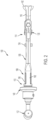
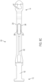
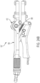
- FIGS. 1-3 , 5 and 6 illustrate an implant extractor 100 in accordance with an exemplary embodiment of the present disclosure.
- the implant extractor 100 includes a second arm 102 having a proximal end 104 and a distal end 106, and a first arm 108 having a proximal end 110 for attachment to an extraction device 112.
- the extraction device 112 can be any suitable extraction device including, without limitation, a T-handle.
- the first arm additionally has a distal end 114 for attachment to a first jaw 116, and an adjustment mechanism 118 including an adjuster 120 and a lever 122.
- the lever has a proximal end 124 engaged with the adjuster and a distal end 126 pivotably connected to the second arm 102 via pivot pin 128.
- the implant extractor 100 additionally comprises a link 130 pivotably connected to the first and second arms via pivot pins 132, 134, the link having a distal end 136 for attachment to a second jaw 138.
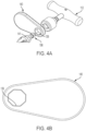
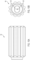
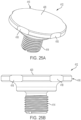
- FIGS. 4A and 4B illustrate that the implant extractor can optionally include a planar laterally projecting strike plate 140 located adjacent the proximal end of the first arm.
- the strike plate includes a proximal face 140a and a distal face 140b and can include an opening e.g., a polygonal opening 139 for receiving a correspondingly shaped base e.g., polygonal base 141 of a quick connect 198, discussed below. So constructed, the strike plate may be rotatably positioned at different angles, and more specifically at different rotated angles about a longitudinal axis of the implant extractor or the implant extractor itself and set at an angle that is most appropriate and comfortable to the user for extraction.
- the polygonal opening in the strike plate and the polygonal base 141 of the quick connect can be octagonal, whereby the strike plate may be placed in any one of eight positions about the implant extractor, or alternatively a polygonal base with a square, pentagon, hexagon, heptagon, nonagon, decagon, dodecagon shape or any number of sides corresponding in number to a plurality of sides of the polygonal opening.
- the extraction device 112 holds the strike plate 140 in place and both are easily removable from the quick connect 198.
- the second arm 102 is configured as best shown in FIGS. 1 , 7A and 7B , and is constructed as an elongated arm having a channel formed by upstanding sidewalls 150, 152. About its midportion the second arm is provided with a pair of notches 146, 148 in the upstanding side walls 150, 152 which are adapted to cooperate with a locking mechanism 154 (described below in connection with FIGS. 16 and 17 ) carried by the lever 122.
- the side walls 150, 152 further include a first pair of aligned openings 156, 158 that receive the pivot pin 128 for pivotably connecting the distal end 126 of the lever 122 to the second arm.
- a through bore 160 that aligns with aligned openings 162, 164 provided in the lower branches 166, 168 of the link 130 ( FIGS. 12A-12C ) to receive the pivot pin 134 to pivotably connect the distal end of the second arm 102 to the lower branches of the link.
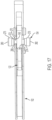
- the side walls 150, 152 include a second pair of aligned openings 170, 172 that receive a pivot pin 174 ( FIGS. 1 , 3 , and 5 ) that likewise passes through a through bore 176 provided at a distal end 178 of a release lever 180 ( FIG. 19 ) for pivotably connecting the distal end of the release lever to the second arm.
- the function of the release lever 180 is described in greater detail in connection with FIG. 19 .
- FIGS. 8A-8E show a first arm body 109 of the first arm. Adjacent the distal end 114 of the first arm body there is provided a through bore 182 that aligns with aligned openings 184, 186 provided in the upper branches 188, 190 of the link 130 ( FIGS. 12A-12C ) to receive the pivot pin 132 to pivotably connect the distal end of the first arm 108 to the upper branches of the link. Also adjacent the distal end of the first arm body is a transverse opening 300 which includes fastener structure 302 configured to releasably retain various forms of extraction devices which are described in greater detail hereinafter.
- the first arm includes a slidable lock 214 for attachment to the first jaw 116, which is discussed in further detail below.
- the first arm also includes the quick connect 198 ( FIG. 3 ) about its proximal end structured to releasably engage with, e.g., a corresponding female quick connection carried by the extraction device 112.
- the corresponding female quick connection includes a biased locking member 199.
- FIGS. 3 and 5 best illustrate the adjustment mechanism 118 of the first arm 108.
- the adjustment mechanism includes the adjuster 120 and the lever 122.
- the adjuster comprises the rotatable knob 196 and the rod 216.
- the rod 216 extends from the rotatable knob and is movable relative to the rotatable knob.
- the rod 216 is a threaded rod ( FIGS. 8E , 9A and 9B ) threadedly engaged with the first arm at the internally threaded through bore 200 as shown in FIG. 8E .
- the rod 216 includes at least one planar side 218, and preferably a pair of opposing planar sides 218A, 218B.
- the rod also includes a non-threaded distal nose 219.
- the rod is sized in length sufficiently such that the distal nose 219 of the rod 216 abuts the proximal end 124 of the lever 122.
- Rotation of the rotatable knob 196 causes rotation of the threaded rod 216 within the internally threaded through bore 200, thereby causing the rod 216 to extend from or retract into the rotatable knob depending on the direction of rotation of the rotatable knob, or in other words move along a direction of a longitudinal axis of the rod. More particularly, rotation of the rotatable knob 196 in a first direction causes the rod 216 to extend from the rotatable knob. In so doing, the distal nose 219 of the rod pushes further against the proximal end 124 of the lever 122. Conversely, rotation of the rotatable knob 196 in a second direction causes the rod 216 to retract into the rotatable knob. In so doing, the proximal end 124 of the lever 122 remains in contact with the distal nose 219 of the rod 216 since it is under the influence of the biasing member 144, discussed below.
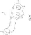
- the lever 122 is structured as best shown in FIGS. 1 , 5 and 11 .
- the lever 122 between its proximal and distal ends 124, 126, the lever 122 includes a first through bore 226 that receives the pivot pin 128 for pivotably connecting the distal end 126 of the lever 122 to the second arm ( FIGS. 3 , 5 and 6 ).
- the lever 122 further includes a second through bore 228 through which the locking mechanism 154 passes (see FIGS. 1-3 , 6 and 16 ).
- FIGS. 12A-12C best show the construction of the link 130.
- the link includes upper and lower branches. Between the upper branches 188, 190 and lower branches 166, 186, the link includes a pair of aligned through bores 230, 232. The through bores 230, 232 receive a pin 234 which holds a second end of the biasing member 144 ( FIGS. 1 , 3 , and 5 ).
- the distal end 136 of the link 130 is provided with a fastener 256 for attaching the second jaw 138 to the link.
- the distal end 114 of the first arm 108 is provided with a fastener 254 for attaching the first jaw 116 to the first arm. As shown in FIG.
- the first and second jaws respectively are structured as best shown in FIGS. 14 and 15 .
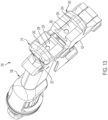
- the first and second jaws respectively include a corresponding recess 260 and 264 to releasably engage respective corresponding detents 258, 262 ( FIG. 13 ) on the distal ends of the first arm and the link.
- the first and second jaws respectively include slidable locks 236 and 238 to slidingly engage a corresponding slidable lock 214, 240 on the first arm 108 and link 130, respectively, as shown in FIG. 13 .
- the corresponding slidable locks on the first arm and link each includes a stop 242, 244.
- the stops 242, 244 are distally extending ledges.
- the stops 242, 244 are engageable by flats 246, 248 respectively provided on the first and second jaws ( FIGS. 14 and 15 ) to limit insertion of the first and second jaws into the first arm and the link.
- the implant extractor further comprises a detent 258 ( FIG 13 ) carried by one of the first jaw and the first arm, or a detent 262 carried by the one of the second jaw and the link.
- the detent 258 is carried by the first arm for engaging a corresponding recess 260 in the first jaw
- the detent 262 is carried by the link for engaging corresponding recess 264 in the second jaw ( FIGS. 13-15 ).
- An exemplary detent can be e.g., a ball detent.
- the detents 258, 262 are urged outwardly toward engagement with recesses 260, 264 by biasing members 266 and 268, such as springs or the like.
- the notch 148 includes an overhang 284 which overlies the first cylindrical portion 272. The overhang prevents dislodgement of the cylindrical portion 272 from the notch 148 and secures the second arm 102 and the lever 122 connected thereto into a locked position.
- a user presses the outer surface 282 of the button 278 until the first cylindrical portion 272 is no longer received in the notch 148 and retained by the overhang 284. With the locking mechanism 154 in such position, the user can separate the second arm from the first arm whereby the first and second jaws are released from clamping engagement with implant 142.
- the implant extractor 100 further comprises a release lever 180 ( FIG. 19 ) on the second arm 102 to release the first and second jaws from clamping engagement with an implant to be extracted.
- the release lever has a knuckle 286 provided adjacent the distal end 178 thereof, and a proximal end 288 projecting from the proximal end 104 of the second arm.
- the proximal end 288 of the release lever is lifted upwardly (as shown in FIG. 19 ) until the knuckle 286 contacts the underside of the lever 122. Further lifting of the release lever operates to withdraw the locking mechanism from the notches 146, 148 and push the second arm 102 away from the first arm 108, thereby allowing the first and second jaws to spread apart.
- the first and second jaws 116, 138 heretofore discussed can be referred to as straight jaws in that the proximal ends of the jaws extend straight from the distal ends of the first arm and the link.
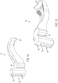
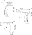
- FIGS. 20A-20C and 21A-21C illustrate an alternative exemplary configuration of the first and second jaws.
- the first and second jaws 116A, 138A illustrated can be referred to as laterally offset jaws.
- intermediate regions of the first and second jaws 116A, 138A include laterally directed bend 290 and 290', respectively, whereby the distal ends of the jaws are laterally offset from the distal ends of the first arm and the link.
- the first and second jaws 116, 138 are operable to releasably clamp a medical implant including, without limitation, e.g., a glenosphere implant 142.
- a user in order to clamp the first and second jaws onto an implant to be extracted, a user first rotates the rotatable knob 196 in a first direction which causes the first and second jaws to separate until opposed lips 292, 294 at respective distal ends of the first and second jaws ( FIGS. 14 and 15 ) are spaced slightly wider than the circumference of the implant to be extracted. More particularly, rotation of the rotatable knob in the first direction causes the distal end 126 of the lever and the second arm 102 to move rearwardly, whereby the link 130 pivots rearwardly and the second jaw 138 moves away from the first jaw 116.
- the user squeezes the first and second arms together whereupon the second arm pivots posteriorly until the locking mechanism 154 becomes seated in the notches 146, 148 of the second arm.
- the first and second jaws are urged into tight clamping engagement with the implant 142.
- the user presses the outer surface 280 of the button 276 until the first cylindrical portion 272 is received in the notch 148, thereby locking the position of the second arm relative to the first arm.
- the user may use the implant extractor to pull the implant from the bone to which it is attached.
- the user may strike the distal face 140b of the strike plate 140 with a hammer, mallet or similar striking tool to dislodge the implant. Once the implant is freed, the user unlocks the locking mechanism 154 and lifts the proximal end 284 of the release lever to open the first and second jaws and release the implant from the implant extractor.
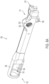
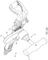
- FIGS. 22A-22C show another exemplary embodiment of an implant extractor 100' according to the subject disclosure.
- the implant extractor 100' is similar in construction to the implant extractor 100. Accordingly, for brevity only those aspects of the implant extractor 100' which materially depart in structure and/or function from the implant extractor 100 will be described in detail.
- the implant extractor 100' comprises a connector member 310 ( FIG. 23 ) constructed and arranged to releasably join an extraction device 312 to the fastener structure of the transverse opening 300 in the first arm 108.
- the extraction device extends from the first arm in a lateral direction opposite the distal ends of the jaws, e.g., laterally extending jaws.
- the extraction device 312 comprises a T-handle 112' and a strike plate 140' (including an upper face 140a'and a lower face 140b') which are releasably connectable to the connector member 310 similar to the manner in which the T-handle and the strike plate are joined to the proximal end of the implant extractor 100, as described above.
- the connector member 310 includes a fastener 314 in the form of external threading at a first end thereof for engaging the corresponding fastener in the form of internal threading 302 of the transverse opening 300. While illustrated as being cooperating threading, the fastener of the connector member and the transverse opening may assume other forms including, without limitation, a J-slot connection, press-fit, Luer lock, slip-fit with ball detent, and the like.
- Adjacent threading 314, the connector member further includes a radially projecting turning knob 316, the exterior of which is desirably provided with grip-enhancing structure such as knurling or, as illustrated, ribs to facilitate threading of the connector member into the transverse opening in the first arm.
- the connector member further includes a quick connect 198' that is structured to releasably engage with a corresponding quick connector, e.g., a biased locking member 199' ( FIG. 22B ) carried by the extraction device 312.
- the T-handle 112' holds the strike plate 140' in place and both are easily removable from the quick connect 198' upon depression of the biased locking member 199'.
- a user may strike the lower face 140b' of the strike plate 140' with a hammer, mallet or the like, in order to dislodge the implant from bone.
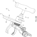
- the implant extractor 100" includes an extraction device 412.
- the extraction device extends from the first arm in a lateral direction on the same side as the distal ends of the jaws, e.g., laterally extending jaws. As shown in FIGS.
- the extraction device includes a fastener 414 in the form of external threading for engaging the corresponding fastener in the form of internal threading 302 of the transverse opening 300 in the first arm 108. While illustrated as being cooperating threading, the fastener structures of the extraction device and the transverse opening may assume other forms including, without limitation, a J-slot connection, press-fit, Luer lock, slip-fit with ball detent, and the like.
- the extraction device further includes a radially projecting turning knob 416, the periphery of which is desirably provided with grip-enhancing structure such as a plurality of notches 418 for receiving a user's fingers to facilitate threading of the extraction device 412 into the transverse opening in the first arm.
- the exposed upper surface 420 defines a striking surface adapted for striking by a hammer, mallet or the like.
- the extraction device 412 When the extraction device 412 is secured to the implant extractor 100" and the implant extractor is clamped on an implant in the manner described above, a user may strike the upper surface 420 of the extraction device with a hammer, mallet or the like, in order to dislodge the implant from bone.
Landscapes
- Health & Medical Sciences (AREA)
- Transplantation (AREA)
- Orthopedic Medicine & Surgery (AREA)
- Heart & Thoracic Surgery (AREA)
- Cardiology (AREA)
- Oral & Maxillofacial Surgery (AREA)
- Engineering & Computer Science (AREA)
- Biomedical Technology (AREA)
- Physical Education & Sports Medicine (AREA)
- Vascular Medicine (AREA)
- Life Sciences & Earth Sciences (AREA)
- Animal Behavior & Ethology (AREA)
- General Health & Medical Sciences (AREA)
- Public Health (AREA)
- Veterinary Medicine (AREA)
- Prostheses (AREA)
Claims (15)
- Implantatextraktor (100), der Folgendes aufweist:einen ersten Arm (108) miteinem proximalen Ende (110),einem distalen Ende (114) zur Befestigung an einer ersten Klemmbacke (116), undeinen zweiten Arm (102) mit einem proximalen Ende (104) und einem distalen Ende (106),wobei der erste Arm weiter aufweist:
einen Einstellmechanismus (118), der Folgendes umfasst:eine Einstellvorrichtung (120) undeinen Hebel (122) mit einem proximalen Ende (124), das mit der Einstellvorrichtung in Eingriff steht, und einem distalen Ende (126), das schwenkbar mit dem zweiten Arm verbunden ist; undwobei der Implantatextraktor weiter ein Verbindungsstück (130) aufweist, das schwenkbar mit dem ersten und zweiten Arm verbunden ist, wobei das Verbindungsstück ein distales Ende (136) zur Befestigung an einer zweiten Klemmbacke (138) aufweist, dadurch gekennzeichnet, dass das proximale Ende (110) des ersten Arms (108) zur Befestigung an einer Extraktionsvorrichtung (112) konfiguriert ist. - Implantatextraktor nach Anspruch 1, der weiter ein Vorspannelement (144) aufweist, das das Verbindungsstück und den ersten Arm vorspannt.
- Implantatextraktor nach einem der Ansprüche 1 oder 2, wobei die Einstellvorrichtung Folgendes aufweist:einen drehbaren Knauf (196); undeine Stange (216), die sich von dem drehbaren Knauf erstreckt und relativ zu dem drehbaren Knauf beweglich ist.
- Implantatextraktor nach Anspruch 3, wobei die Stange eine Gewindestange ist, die mit dem ersten Arm in Gewindeeingriff steht, oder wobei die Stange am proximalen Ende des Hebels anliegt.
- Implantatextraktor nach einem der Ansprüche 3 oder 4, wobei die Stange mindestens eine ebene Seite (218) aufweist.
- Implantatextraktor nach Anspruch 5, wobei der drehbare Knauf eine Öffnung (220) mit einer ebenen Seite (222) aufweist, die mit der ebenen Seite der Stange zusammenwirkt.
- Implantatextraktor nach einem der Ansprüche 3 - 5, wobei der erste Arm einen Käfig (192) mit einer Öffnung (194) zur Aufnahme des drehbaren Knaufs aufweist, oder wobei der erste Arm einen Schlitz (202) zur Aufnahme der Stange aufweist.
- Implantatextraktor nach einem der Ansprüche 1-7, wobei der erste Arm eine Schnellverbindung (198) um sein proximales Ende herum aufweist, oder wobei der erste Arm eine transversale Öffnung (300) mit einer Befestigungsstruktur (302) aufweist, die so konfiguriert ist, dass sie eine Extraktionsvorrichtung (112) lösbar festhält.
- Implantatextraktor nach einem der Ansprüche 1 - 8, der weiter eine erste Klemmbacke (116), die lösbar am distalen Ende des ersten Arms befestigt werden kann, und eine zweite Klemmbacke (138) aufweist, die lösbar am distalen Ende der Verbindung befestigt werden kann.
- Implantatextraktor nach Anspruch 9, wobei die erste und die zweite Klemmbacke jeweils eine verschiebbare Verriegelung (236, 238) aufweisen, die gleitend in eine entsprechende verschiebbare Verriegelung (214, 240) am ersten Arm bzw. am Verbindungsstück eingreift.
- Implantatextraktor nach Anspruch 10, wobei die entsprechende verschiebbare Verriegelung an dem ersten Arm und dem Verbindungsstück jeweils einen Anschlag (242, 244) aufweist.
- Implantatextraktor nach einem der Ansprüche 10 oder 11, wobei die verschiebbare Verriegelung eine Schwalbenschwanzverbindung (250, 252, 254, 256) ist, oder wobei die verschiebbare Verriegelung an jeder der ersten und zweiten Klemmbacken eine männliche Schwalbenschwanzverbindung (250, 252) ist und die entsprechende verschiebbare Verriegelung an jedem des ersten Arms und der Verbindung eine weibliche Schwalbenschwanzverbindung (254, 256) ist.
- Implantatextraktor nach einem der Ansprüche 10 - 12, der ferner eine von der ersten Klemmbacke oder dem ersten Arm getragene Arretierung (258) oder eine von der zweiten Klemmbacke oder dem Verbindungsstück getragene Arretierung (262) aufweist.
- Implantatextraktor nach einem der Ansprüche 10-13, der weiter einen Lösehebel (180) am zweiten Arm aufweist, um die erste und zweite Klemmbacke aus dem Klemmeingriff mit einem zu extrahierenden Implantat (142) zu lösen.
- Implantatextraktor nach einem der Ansprüche 1-14, der weiterhin einen Verriegelungsmechanismus (154) an dem Hebel aufweist, der zwischen einer verriegelten Position und einer entriegelten Position beweglich ist, wobei der Verriegelungsmechanismus in der verriegelten Position den Klemmeingriff der ersten und zweiten Klemmbacken aufrechterhält und in der entriegelten Position die Freigabe der ersten und zweiten Klemmbacken aus dem Klemmeingriff mit einem zu extrahierenden Implantat (142) ermöglicht.
Applications Claiming Priority (1)
| Application Number | Priority Date | Filing Date | Title |
|---|---|---|---|
| US202062991940P | 2020-03-19 | 2020-03-19 |
Publications (3)
| Publication Number | Publication Date |
|---|---|
| EP3881806A1 EP3881806A1 (de) | 2021-09-22 |
| EP3881806B1 true EP3881806B1 (de) | 2024-06-12 |
| EP3881806C0 EP3881806C0 (de) | 2024-06-12 |
Family
ID=75223292
Family Applications (1)
| Application Number | Title | Priority Date | Filing Date |
|---|---|---|---|
| EP21382229.9A Active EP3881806B1 (de) | 2020-03-19 | 2021-03-22 | Implantatextraktor |
Country Status (2)
| Country | Link |
|---|---|
| US (3) | US12383413B2 (de) |
| EP (1) | EP3881806B1 (de) |
Families Citing this family (12)
| Publication number | Priority date | Publication date | Assignee | Title |
|---|---|---|---|---|
| US12023253B2 (en) | 2014-01-24 | 2024-07-02 | Howmedica Osteonics Corp. | Humeral implant anchor system |
| US10456264B2 (en) | 2014-01-24 | 2019-10-29 | Tornier, Inc. | Humeral implant anchor system |
| US10463499B2 (en) | 2016-03-25 | 2019-11-05 | Tornier, Inc. | Stemless shoulder implant with fixation components |
| WO2018022227A1 (en) | 2016-07-28 | 2018-02-01 | Tornier, Inc. | Stemless prosthesis anchor component |
| CA3076502A1 (en) | 2017-09-25 | 2019-03-28 | Tornier, Inc. | Patient specific stemless prosthesis anchor components |
| US11399948B2 (en) | 2017-12-11 | 2022-08-02 | Howmedica Osteonics Corp. | Stemless prosthesis anchor components and kits |
| AU2019355854B2 (en) | 2018-10-02 | 2022-10-20 | Howmedica Osteonics Corp. | Shoulder prosthesis components and assemblies |
| AU2020360410B2 (en) | 2019-10-01 | 2023-03-02 | Howmedica Osteonics Corp. | Shoulder prosthesis components and assemblies |
| US11779468B2 (en) * | 2020-04-14 | 2023-10-10 | Shukla Medical | Implant extractor |
| USD1067031S1 (en) | 2022-05-06 | 2025-03-18 | Shukla Medical | Tool attachment device |
| AU2024200100B2 (en) * | 2023-01-31 | 2026-02-12 | Shukla Medical | Surgical extractor with a ratcheting handle device |
| WO2025224761A1 (en) * | 2024-04-26 | 2025-10-30 | Meril Corporation (I) Private Limited | Femoral impactor extractor |
Family Cites Families (12)
| Publication number | Priority date | Publication date | Assignee | Title |
|---|---|---|---|---|
| US244269A (en) * | 1881-07-12 | Pipe-tongs | ||
| US1348832A (en) * | 1919-08-11 | 1920-08-03 | Magnan August | Wrench |
| US2942508A (en) * | 1957-09-17 | 1960-06-28 | John J Bannister | Locking pliers |
| US6041680A (en) * | 1998-11-24 | 2000-03-28 | Wang; Yen-Yu | Pincers |
| US20060200162A1 (en) | 2005-02-21 | 2006-09-07 | Zimmer Technology, Inc. | Total knee arthroplasty instruments |
| US7587791B2 (en) * | 2006-01-18 | 2009-09-15 | Mou-Tang Liou | Tool |
| US20150246432A1 (en) | 2014-02-28 | 2015-09-03 | Irwin Industrial Tool Company | Locking pliers with customizable jaws |
| US9682462B2 (en) * | 2015-01-29 | 2017-06-20 | Harry Wong | Push-pull pliers with hammers |
| US10085852B2 (en) * | 2015-03-20 | 2018-10-02 | Shukla Medical | Locking grip orthopedic implant extraction tool |
| US11439380B2 (en) | 2015-09-04 | 2022-09-13 | Medos International Sarl | Surgical instrument connectors and related methods |
| US10786368B2 (en) * | 2015-12-30 | 2020-09-29 | Nuvasive, Inc. | Interfixated vertebral body replacement and insertion methods |
| WO2019051491A1 (en) * | 2017-09-11 | 2019-03-14 | Milwaukee Electric Tool Corporation | LOCKING SECTIONS WITH MOBILE JAW SECTION INCREASING TORQUE |
-
2021
- 2021-03-17 US US17/204,385 patent/US12383413B2/en active Active
- 2021-03-22 EP EP21382229.9A patent/EP3881806B1/de active Active
-
2025
- 2025-07-18 US US19/273,259 patent/US20250339291A1/en active Pending
- 2025-07-18 US US19/273,359 patent/US20250339292A1/en active Pending
Also Published As
| Publication number | Publication date |
|---|---|
| EP3881806C0 (de) | 2024-06-12 |
| US20250339291A1 (en) | 2025-11-06 |
| US20250339292A1 (en) | 2025-11-06 |
| US20210290411A1 (en) | 2021-09-23 |
| US12383413B2 (en) | 2025-08-12 |
| EP3881806A1 (de) | 2021-09-22 |
Similar Documents
| Publication | Publication Date | Title |
|---|---|---|
| EP3881806B1 (de) | Implantatextraktor | |
| AU2020206707B2 (en) | Implant extractor | |
| US11779468B2 (en) | Implant extractor | |
| US20200222205A1 (en) | Implant extractor tool | |
| US12109130B2 (en) | Surgical extractor | |
| US7588537B2 (en) | Connector with safety latch for a surgical retractor | |
| EP4021352B1 (de) | Implantatextraktionsvorrichtung | |
| US20220023071A1 (en) | Handle assembly for a medical device instrument | |
| US20030074807A1 (en) | Connector for attaching and detaching attachment to/from shoe sole | |
| US20060149284A1 (en) | Insertion device and method for inserting a member within the body | |
| CA2117106A1 (en) | Handle apparatus | |
| US11937862B2 (en) | Striking assembly and surgical tool assembly | |
| US20230000644A1 (en) | Implant extractor | |
| US20230120086A1 (en) | Surgical extractor | |
| US12491089B2 (en) | Implant extractor | |
| AU2024200100B2 (en) | Surgical extractor with a ratcheting handle device | |
| US12594109B2 (en) | Surgical extractor with a ratcheting handle device | |
| GB2273209A (en) | Retaining sliding lid of plug |
Legal Events
| Date | Code | Title | Description |
|---|---|---|---|
| PUAI | Public reference made under article 153(3) epc to a published international application that has entered the european phase |
Free format text: ORIGINAL CODE: 0009012 |
|
| STAA | Information on the status of an ep patent application or granted ep patent |
Free format text: STATUS: THE APPLICATION HAS BEEN PUBLISHED |
|
| AK | Designated contracting states |
Kind code of ref document: A1 Designated state(s): AL AT BE BG CH CY CZ DE DK EE ES FI FR GB GR HR HU IE IS IT LI LT LU LV MC MK MT NL NO PL PT RO RS SE SI SK SM TR |
|
| STAA | Information on the status of an ep patent application or granted ep patent |
Free format text: STATUS: REQUEST FOR EXAMINATION WAS MADE |
|
| 17P | Request for examination filed |
Effective date: 20220103 |
|
| RBV | Designated contracting states (corrected) |
Designated state(s): AL AT BE BG CH CY CZ DE DK EE ES FI FR GB GR HR HU IE IS IT LI LT LU LV MC MK MT NL NO PL PT RO RS SE SI SK SM TR |
|
| P01 | Opt-out of the competence of the unified patent court (upc) registered |
Effective date: 20230420 |
|
| GRAP | Despatch of communication of intention to grant a patent |
Free format text: ORIGINAL CODE: EPIDOSNIGR1 |
|
| STAA | Information on the status of an ep patent application or granted ep patent |
Free format text: STATUS: GRANT OF PATENT IS INTENDED |
|
| RIC1 | Information provided on ipc code assigned before grant |
Ipc: A61F 2/46 20060101AFI20240221BHEP |
|
| INTG | Intention to grant announced |
Effective date: 20240311 |
|
| GRAS | Grant fee paid |
Free format text: ORIGINAL CODE: EPIDOSNIGR3 |
|
| GRAA | (expected) grant |
Free format text: ORIGINAL CODE: 0009210 |
|
| STAA | Information on the status of an ep patent application or granted ep patent |
Free format text: STATUS: THE PATENT HAS BEEN GRANTED |
|
| AK | Designated contracting states |
Kind code of ref document: B1 Designated state(s): AL AT BE BG CH CY CZ DE DK EE ES FI FR GB GR HR HU IE IS IT LI LT LU LV MC MK MT NL NO PL PT RO RS SE SI SK SM TR |
|
| REG | Reference to a national code |
Ref country code: GB Ref legal event code: FG4D |
|
| REG | Reference to a national code |
Ref country code: CH Ref legal event code: EP |
|
| REG | Reference to a national code |
Ref country code: DE Ref legal event code: R096 Ref document number: 602021014321 Country of ref document: DE |
|
| REG | Reference to a national code |
Ref country code: IE Ref legal event code: FG4D |
|
| U01 | Request for unitary effect filed |
Effective date: 20240613 |
|
| U07 | Unitary effect registered |
Designated state(s): AT BE BG DE DK EE FI FR IT LT LU LV MT NL PT SE SI Effective date: 20240625 |
|
| P04 | Withdrawal of opt-out of the competence of the unified patent court (upc) registered |
Free format text: CASE NUMBER: APP_37137/2024 Effective date: 20240620 |
|
| PG25 | Lapsed in a contracting state [announced via postgrant information from national office to epo] |
Ref country code: HR Free format text: LAPSE BECAUSE OF FAILURE TO SUBMIT A TRANSLATION OF THE DESCRIPTION OR TO PAY THE FEE WITHIN THE PRESCRIBED TIME-LIMIT Effective date: 20240612 |
|
| PG25 | Lapsed in a contracting state [announced via postgrant information from national office to epo] |
Ref country code: GR Free format text: LAPSE BECAUSE OF FAILURE TO SUBMIT A TRANSLATION OF THE DESCRIPTION OR TO PAY THE FEE WITHIN THE PRESCRIBED TIME-LIMIT Effective date: 20240913 |
|
| PG25 | Lapsed in a contracting state [announced via postgrant information from national office to epo] |
Ref country code: ES Free format text: LAPSE BECAUSE OF FAILURE TO SUBMIT A TRANSLATION OF THE DESCRIPTION OR TO PAY THE FEE WITHIN THE PRESCRIBED TIME-LIMIT Effective date: 20240612 |
|
| PG25 | Lapsed in a contracting state [announced via postgrant information from national office to epo] |
Ref country code: NO Free format text: LAPSE BECAUSE OF FAILURE TO SUBMIT A TRANSLATION OF THE DESCRIPTION OR TO PAY THE FEE WITHIN THE PRESCRIBED TIME-LIMIT Effective date: 20240912 Ref country code: HR Free format text: LAPSE BECAUSE OF FAILURE TO SUBMIT A TRANSLATION OF THE DESCRIPTION OR TO PAY THE FEE WITHIN THE PRESCRIBED TIME-LIMIT Effective date: 20240612 Ref country code: GR Free format text: LAPSE BECAUSE OF FAILURE TO SUBMIT A TRANSLATION OF THE DESCRIPTION OR TO PAY THE FEE WITHIN THE PRESCRIBED TIME-LIMIT Effective date: 20240913 Ref country code: ES Free format text: LAPSE BECAUSE OF FAILURE TO SUBMIT A TRANSLATION OF THE DESCRIPTION OR TO PAY THE FEE WITHIN THE PRESCRIBED TIME-LIMIT Effective date: 20240612 Ref country code: RS Free format text: LAPSE BECAUSE OF FAILURE TO SUBMIT A TRANSLATION OF THE DESCRIPTION OR TO PAY THE FEE WITHIN THE PRESCRIBED TIME-LIMIT Effective date: 20240912 |
|
| P05 | Withdrawal of opt-out of the competence of the unified patent court (upc) changed |
Free format text: CASE NUMBER: APP_37137/2024 Effective date: 20240625 |
|
| PG25 | Lapsed in a contracting state [announced via postgrant information from national office to epo] |
Ref country code: PL Free format text: LAPSE BECAUSE OF FAILURE TO SUBMIT A TRANSLATION OF THE DESCRIPTION OR TO PAY THE FEE WITHIN THE PRESCRIBED TIME-LIMIT Effective date: 20240612 |
|
| PG25 | Lapsed in a contracting state [announced via postgrant information from national office to epo] |
Ref country code: IS Free format text: LAPSE BECAUSE OF FAILURE TO SUBMIT A TRANSLATION OF THE DESCRIPTION OR TO PAY THE FEE WITHIN THE PRESCRIBED TIME-LIMIT Effective date: 20241012 |
|
| PG25 | Lapsed in a contracting state [announced via postgrant information from national office to epo] |
Ref country code: CZ Free format text: LAPSE BECAUSE OF FAILURE TO SUBMIT A TRANSLATION OF THE DESCRIPTION OR TO PAY THE FEE WITHIN THE PRESCRIBED TIME-LIMIT Effective date: 20240612 |
|
| PG25 | Lapsed in a contracting state [announced via postgrant information from national office to epo] |
Ref country code: RO Free format text: LAPSE BECAUSE OF FAILURE TO SUBMIT A TRANSLATION OF THE DESCRIPTION OR TO PAY THE FEE WITHIN THE PRESCRIBED TIME-LIMIT Effective date: 20240612 Ref country code: SK Free format text: LAPSE BECAUSE OF FAILURE TO SUBMIT A TRANSLATION OF THE DESCRIPTION OR TO PAY THE FEE WITHIN THE PRESCRIBED TIME-LIMIT Effective date: 20240612 |
|
| PG25 | Lapsed in a contracting state [announced via postgrant information from national office to epo] |
Ref country code: SM Free format text: LAPSE BECAUSE OF FAILURE TO SUBMIT A TRANSLATION OF THE DESCRIPTION OR TO PAY THE FEE WITHIN THE PRESCRIBED TIME-LIMIT Effective date: 20240612 |
|
| PG25 | Lapsed in a contracting state [announced via postgrant information from national office to epo] |
Ref country code: SM Free format text: LAPSE BECAUSE OF FAILURE TO SUBMIT A TRANSLATION OF THE DESCRIPTION OR TO PAY THE FEE WITHIN THE PRESCRIBED TIME-LIMIT Effective date: 20240612 Ref country code: SK Free format text: LAPSE BECAUSE OF FAILURE TO SUBMIT A TRANSLATION OF THE DESCRIPTION OR TO PAY THE FEE WITHIN THE PRESCRIBED TIME-LIMIT Effective date: 20240612 Ref country code: RO Free format text: LAPSE BECAUSE OF FAILURE TO SUBMIT A TRANSLATION OF THE DESCRIPTION OR TO PAY THE FEE WITHIN THE PRESCRIBED TIME-LIMIT Effective date: 20240612 Ref country code: PL Free format text: LAPSE BECAUSE OF FAILURE TO SUBMIT A TRANSLATION OF THE DESCRIPTION OR TO PAY THE FEE WITHIN THE PRESCRIBED TIME-LIMIT Effective date: 20240612 Ref country code: IS Free format text: LAPSE BECAUSE OF FAILURE TO SUBMIT A TRANSLATION OF THE DESCRIPTION OR TO PAY THE FEE WITHIN THE PRESCRIBED TIME-LIMIT Effective date: 20241012 Ref country code: CZ Free format text: LAPSE BECAUSE OF FAILURE TO SUBMIT A TRANSLATION OF THE DESCRIPTION OR TO PAY THE FEE WITHIN THE PRESCRIBED TIME-LIMIT Effective date: 20240612 |
|
| PLBE | No opposition filed within time limit |
Free format text: ORIGINAL CODE: 0009261 |
|
| STAA | Information on the status of an ep patent application or granted ep patent |
Free format text: STATUS: NO OPPOSITION FILED WITHIN TIME LIMIT |
|
| PGFP | Annual fee paid to national office [announced via postgrant information from national office to epo] |
Ref country code: GB Payment date: 20250327 Year of fee payment: 5 |
|
| U20 | Renewal fee for the european patent with unitary effect paid |
Year of fee payment: 5 Effective date: 20250327 |
|
| 26N | No opposition filed |
Effective date: 20250313 |
|
| PG25 | Lapsed in a contracting state [announced via postgrant information from national office to epo] |
Ref country code: MC Free format text: LAPSE BECAUSE OF FAILURE TO SUBMIT A TRANSLATION OF THE DESCRIPTION OR TO PAY THE FEE WITHIN THE PRESCRIBED TIME-LIMIT Effective date: 20240612 |
|
| REG | Reference to a national code |
Ref country code: CH Ref legal event code: H13 Free format text: ST27 STATUS EVENT CODE: U-0-0-H10-H13 (AS PROVIDED BY THE NATIONAL OFFICE) Effective date: 20251023 |
|
| PG25 | Lapsed in a contracting state [announced via postgrant information from national office to epo] |
Ref country code: CH Free format text: LAPSE BECAUSE OF NON-PAYMENT OF DUE FEES Effective date: 20250331 |
|
| PG25 | Lapsed in a contracting state [announced via postgrant information from national office to epo] |
Ref country code: IE Free format text: LAPSE BECAUSE OF NON-PAYMENT OF DUE FEES Effective date: 20250322 |