EP3881758B1 - Method, apparatus and system for acquiring vascular assessment parameter on basis of angiographic image - Google Patents
Method, apparatus and system for acquiring vascular assessment parameter on basis of angiographic image Download PDFInfo
- Publication number
- EP3881758B1 EP3881758B1 EP19885173.5A EP19885173A EP3881758B1 EP 3881758 B1 EP3881758 B1 EP 3881758B1 EP 19885173 A EP19885173 A EP 19885173A EP 3881758 B1 EP3881758 B1 EP 3881758B1
- Authority
- EP
- European Patent Office
- Prior art keywords
- coronary artery
- pressure
- blood vessel
- acquiring
- waveform
- Prior art date
- Legal status (The legal status is an assumption and is not a legal conclusion. Google has not performed a legal analysis and makes no representation as to the accuracy of the status listed.)
- Active
Links
Images



Classifications
-
- A—HUMAN NECESSITIES
- A61—MEDICAL OR VETERINARY SCIENCE; HYGIENE
- A61B—DIAGNOSIS; SURGERY; IDENTIFICATION
- A61B5/00—Measuring for diagnostic purposes; Identification of persons
- A61B5/0033—Features or image-related aspects of imaging apparatus, e.g. for MRI, optical tomography or impedance tomography apparatus; Arrangements of imaging apparatus in a room
- A61B5/004—Features or image-related aspects of imaging apparatus, e.g. for MRI, optical tomography or impedance tomography apparatus; Arrangements of imaging apparatus in a room adapted for image acquisition of a particular organ or body part
- A61B5/0044—Features or image-related aspects of imaging apparatus, e.g. for MRI, optical tomography or impedance tomography apparatus; Arrangements of imaging apparatus in a room adapted for image acquisition of a particular organ or body part for the heart
-
- A—HUMAN NECESSITIES
- A61—MEDICAL OR VETERINARY SCIENCE; HYGIENE
- A61B—DIAGNOSIS; SURGERY; IDENTIFICATION
- A61B5/00—Measuring for diagnostic purposes; Identification of persons
- A61B5/02—Detecting, measuring or recording for evaluating the cardiovascular system, e.g. pulse, heart rate, blood pressure or blood flow
- A61B5/02007—Evaluating blood vessel condition, e.g. elasticity, compliance
-
- A—HUMAN NECESSITIES
- A61—MEDICAL OR VETERINARY SCIENCE; HYGIENE
- A61B—DIAGNOSIS; SURGERY; IDENTIFICATION
- A61B5/00—Measuring for diagnostic purposes; Identification of persons
- A61B5/02—Detecting, measuring or recording for evaluating the cardiovascular system, e.g. pulse, heart rate, blood pressure or blood flow
- A61B5/021—Measuring pressure in heart or blood vessels
- A61B5/0215—Measuring pressure in heart or blood vessels by means inserted into the body
-
- A—HUMAN NECESSITIES
- A61—MEDICAL OR VETERINARY SCIENCE; HYGIENE
- A61B—DIAGNOSIS; SURGERY; IDENTIFICATION
- A61B5/00—Measuring for diagnostic purposes; Identification of persons
- A61B5/02—Detecting, measuring or recording for evaluating the cardiovascular system, e.g. pulse, heart rate, blood pressure or blood flow
- A61B5/026—Measuring blood flow
-
- A—HUMAN NECESSITIES
- A61—MEDICAL OR VETERINARY SCIENCE; HYGIENE
- A61B—DIAGNOSIS; SURGERY; IDENTIFICATION
- A61B5/00—Measuring for diagnostic purposes; Identification of persons
- A61B5/02—Detecting, measuring or recording for evaluating the cardiovascular system, e.g. pulse, heart rate, blood pressure or blood flow
- A61B5/026—Measuring blood flow
- A61B5/0275—Measuring blood flow using tracers, e.g. dye dilution
-
- A—HUMAN NECESSITIES
- A61—MEDICAL OR VETERINARY SCIENCE; HYGIENE
- A61B—DIAGNOSIS; SURGERY; IDENTIFICATION
- A61B5/00—Measuring for diagnostic purposes; Identification of persons
- A61B5/72—Signal processing specially adapted for physiological signals or for diagnostic purposes
- A61B5/7235—Details of waveform analysis
- A61B5/7253—Details of waveform analysis characterised by using transforms
- A61B5/7257—Details of waveform analysis characterised by using transforms using Fourier transforms
-
- A—HUMAN NECESSITIES
- A61—MEDICAL OR VETERINARY SCIENCE; HYGIENE
- A61B—DIAGNOSIS; SURGERY; IDENTIFICATION
- A61B6/00—Apparatus or devices for radiation diagnosis; Apparatus or devices for radiation diagnosis combined with radiation therapy equipment
- A61B6/50—Apparatus or devices for radiation diagnosis; Apparatus or devices for radiation diagnosis combined with radiation therapy equipment specially adapted for specific body parts; specially adapted for specific clinical applications
- A61B6/504—Apparatus or devices for radiation diagnosis; Apparatus or devices for radiation diagnosis combined with radiation therapy equipment specially adapted for specific body parts; specially adapted for specific clinical applications for diagnosis of blood vessels, e.g. by angiography
-
- A—HUMAN NECESSITIES
- A61—MEDICAL OR VETERINARY SCIENCE; HYGIENE
- A61B—DIAGNOSIS; SURGERY; IDENTIFICATION
- A61B6/00—Apparatus or devices for radiation diagnosis; Apparatus or devices for radiation diagnosis combined with radiation therapy equipment
- A61B6/52—Devices using data or image processing specially adapted for radiation diagnosis
- A61B6/5211—Devices using data or image processing specially adapted for radiation diagnosis involving processing of medical diagnostic data
- A61B6/5217—Devices using data or image processing specially adapted for radiation diagnosis involving processing of medical diagnostic data extracting a diagnostic or physiological parameter from medical diagnostic data
-
- G—PHYSICS
- G06—COMPUTING OR CALCULATING; COUNTING
- G06T—IMAGE DATA PROCESSING OR GENERATION, IN GENERAL
- G06T17/00—Three-dimensional [3D] modelling for computer graphics
- G06T17/20—Finite element generation, e.g. wire-frame surface description, tesselation
-
- G—PHYSICS
- G06—COMPUTING OR CALCULATING; COUNTING
- G06T—IMAGE DATA PROCESSING OR GENERATION, IN GENERAL
- G06T7/00—Image analysis
- G06T7/0002—Inspection of images, e.g. flaw detection
- G06T7/0012—Biomedical image inspection
-
- G—PHYSICS
- G16—INFORMATION AND COMMUNICATION TECHNOLOGY [ICT] SPECIALLY ADAPTED FOR SPECIFIC APPLICATION FIELDS
- G16H—HEALTHCARE INFORMATICS, i.e. INFORMATION AND COMMUNICATION TECHNOLOGY [ICT] SPECIALLY ADAPTED FOR THE HANDLING OR PROCESSING OF MEDICAL OR HEALTHCARE DATA
- G16H20/00—ICT specially adapted for therapies or health-improving plans, e.g. for handling prescriptions, for steering therapy or for monitoring patient compliance
- G16H20/10—ICT specially adapted for therapies or health-improving plans, e.g. for handling prescriptions, for steering therapy or for monitoring patient compliance relating to drugs or medications, e.g. for ensuring correct administration to patients
- G16H20/17—ICT specially adapted for therapies or health-improving plans, e.g. for handling prescriptions, for steering therapy or for monitoring patient compliance relating to drugs or medications, e.g. for ensuring correct administration to patients delivered via infusion or injection
-
- G—PHYSICS
- G16—INFORMATION AND COMMUNICATION TECHNOLOGY [ICT] SPECIALLY ADAPTED FOR SPECIFIC APPLICATION FIELDS
- G16H—HEALTHCARE INFORMATICS, i.e. INFORMATION AND COMMUNICATION TECHNOLOGY [ICT] SPECIALLY ADAPTED FOR THE HANDLING OR PROCESSING OF MEDICAL OR HEALTHCARE DATA
- G16H30/00—ICT specially adapted for the handling or processing of medical images
- G16H30/40—ICT specially adapted for the handling or processing of medical images for processing medical images, e.g. editing
-
- G—PHYSICS
- G16—INFORMATION AND COMMUNICATION TECHNOLOGY [ICT] SPECIALLY ADAPTED FOR SPECIFIC APPLICATION FIELDS
- G16H—HEALTHCARE INFORMATICS, i.e. INFORMATION AND COMMUNICATION TECHNOLOGY [ICT] SPECIALLY ADAPTED FOR THE HANDLING OR PROCESSING OF MEDICAL OR HEALTHCARE DATA
- G16H40/00—ICT specially adapted for the management or administration of healthcare resources or facilities; ICT specially adapted for the management or operation of medical equipment or devices
- G16H40/60—ICT specially adapted for the management or administration of healthcare resources or facilities; ICT specially adapted for the management or operation of medical equipment or devices for the operation of medical equipment or devices
- G16H40/63—ICT specially adapted for the management or administration of healthcare resources or facilities; ICT specially adapted for the management or operation of medical equipment or devices for the operation of medical equipment or devices for local operation
-
- G—PHYSICS
- G16—INFORMATION AND COMMUNICATION TECHNOLOGY [ICT] SPECIALLY ADAPTED FOR SPECIFIC APPLICATION FIELDS
- G16H—HEALTHCARE INFORMATICS, i.e. INFORMATION AND COMMUNICATION TECHNOLOGY [ICT] SPECIALLY ADAPTED FOR THE HANDLING OR PROCESSING OF MEDICAL OR HEALTHCARE DATA
- G16H50/00—ICT specially adapted for medical diagnosis, medical simulation or medical data mining; ICT specially adapted for detecting, monitoring or modelling epidemics or pandemics
- G16H50/30—ICT specially adapted for medical diagnosis, medical simulation or medical data mining; ICT specially adapted for detecting, monitoring or modelling epidemics or pandemics for calculating health indices; for individual health risk assessment
-
- G—PHYSICS
- G16—INFORMATION AND COMMUNICATION TECHNOLOGY [ICT] SPECIALLY ADAPTED FOR SPECIFIC APPLICATION FIELDS
- G16H—HEALTHCARE INFORMATICS, i.e. INFORMATION AND COMMUNICATION TECHNOLOGY [ICT] SPECIALLY ADAPTED FOR THE HANDLING OR PROCESSING OF MEDICAL OR HEALTHCARE DATA
- G16H50/00—ICT specially adapted for medical diagnosis, medical simulation or medical data mining; ICT specially adapted for detecting, monitoring or modelling epidemics or pandemics
- G16H50/50—ICT specially adapted for medical diagnosis, medical simulation or medical data mining; ICT specially adapted for detecting, monitoring or modelling epidemics or pandemics for simulation or modelling of medical disorders
-
- A—HUMAN NECESSITIES
- A61—MEDICAL OR VETERINARY SCIENCE; HYGIENE
- A61B—DIAGNOSIS; SURGERY; IDENTIFICATION
- A61B2505/00—Evaluating, monitoring or diagnosing in the context of a particular type of medical care
- A61B2505/05—Surgical care
-
- A—HUMAN NECESSITIES
- A61—MEDICAL OR VETERINARY SCIENCE; HYGIENE
- A61B—DIAGNOSIS; SURGERY; IDENTIFICATION
- A61B2576/00—Medical imaging apparatus involving image processing or analysis
- A61B2576/02—Medical imaging apparatus involving image processing or analysis specially adapted for a particular organ or body part
- A61B2576/023—Medical imaging apparatus involving image processing or analysis specially adapted for a particular organ or body part for the heart
-
- A—HUMAN NECESSITIES
- A61—MEDICAL OR VETERINARY SCIENCE; HYGIENE
- A61B—DIAGNOSIS; SURGERY; IDENTIFICATION
- A61B5/00—Measuring for diagnostic purposes; Identification of persons
- A61B5/02—Detecting, measuring or recording for evaluating the cardiovascular system, e.g. pulse, heart rate, blood pressure or blood flow
- A61B5/026—Measuring blood flow
- A61B5/0261—Measuring blood flow using optical means, e.g. infrared light
-
- A—HUMAN NECESSITIES
- A61—MEDICAL OR VETERINARY SCIENCE; HYGIENE
- A61B—DIAGNOSIS; SURGERY; IDENTIFICATION
- A61B6/00—Apparatus or devices for radiation diagnosis; Apparatus or devices for radiation diagnosis combined with radiation therapy equipment
- A61B6/52—Devices using data or image processing specially adapted for radiation diagnosis
- A61B6/5205—Devices using data or image processing specially adapted for radiation diagnosis involving processing of raw data to produce diagnostic data
-
- G—PHYSICS
- G06—COMPUTING OR CALCULATING; COUNTING
- G06T—IMAGE DATA PROCESSING OR GENERATION, IN GENERAL
- G06T2207/00—Indexing scheme for image analysis or image enhancement
- G06T2207/10—Image acquisition modality
- G06T2207/10016—Video; Image sequence
-
- G—PHYSICS
- G06—COMPUTING OR CALCULATING; COUNTING
- G06T—IMAGE DATA PROCESSING OR GENERATION, IN GENERAL
- G06T2207/00—Indexing scheme for image analysis or image enhancement
- G06T2207/10—Image acquisition modality
- G06T2207/10116—X-ray image
- G06T2207/10121—Fluoroscopy
-
- G—PHYSICS
- G06—COMPUTING OR CALCULATING; COUNTING
- G06T—IMAGE DATA PROCESSING OR GENERATION, IN GENERAL
- G06T2207/00—Indexing scheme for image analysis or image enhancement
- G06T2207/20—Special algorithmic details
- G06T2207/20048—Transform domain processing
- G06T2207/20056—Discrete and fast Fourier transform, [DFT, FFT]
-
- G—PHYSICS
- G06—COMPUTING OR CALCULATING; COUNTING
- G06T—IMAGE DATA PROCESSING OR GENERATION, IN GENERAL
- G06T2207/00—Indexing scheme for image analysis or image enhancement
- G06T2207/30—Subject of image; Context of image processing
- G06T2207/30004—Biomedical image processing
- G06T2207/30101—Blood vessel; Artery; Vein; Vascular
-
- G—PHYSICS
- G06—COMPUTING OR CALCULATING; COUNTING
- G06T—IMAGE DATA PROCESSING OR GENERATION, IN GENERAL
- G06T2207/00—Indexing scheme for image analysis or image enhancement
- G06T2207/30—Subject of image; Context of image processing
- G06T2207/30004—Biomedical image processing
- G06T2207/30101—Blood vessel; Artery; Vein; Vascular
- G06T2207/30104—Vascular flow; Blood flow; Perfusion
Definitions
- the disclosure relates to the technical field of coronary artery, and in particular to, a method, a device, a coronary artery analysis system and a computer storage medium for acquiring coronary artery blood vessel evaluation parameters based on an angiographic image.
- cardioblood vessel diseases According to statistics from the World Health Organization, cardioblood vessel diseases have become the "top killer" of human health. In recent years, analysis of the physiology and pathological behaviors of the cardioblood vessel diseases using hemodynamics has also become a very important method for the diagnosis of the cardioblood vessel diseases.
- Fractional flow reserve may indicate an influence of coronary artery stenosis lesion on distal blood flow and diagnosis of myocardial ischemia, and thus has become a recognized indicator of the functional evaluation of the coronary artery stenosis.
- FFR is defined as a ratio of the maximum blood flow to the myocardium in the innervated region provided by the coronary artery stenosis to the maximum blood flow to the myocardium provided by the same normal coronary artery.
- intracoronary injection or intravenous injection of adenosine or ATP is required for maximum hyperemia of the myocardium, and the injection of adenosine or ATP will decrease the aortic pressure and will cause a certain side effects, such as atrioventricular block, sinus bradycardia, and sinus arrest, and contraindications include second degree atrioventricular block, third degree atrioventricular block, sinoatrial node diseases, tracheal or bronchial asthma, and adenosine allergy.
- Instantaneous wave-free ratio can provide a method for measuring intracoronary pressure similar to Fractional Flow Reserve (FFR).
- FFR Fractional Flow Reserve
- the existing measurement methods for coronary artery blood vessel evaluation parameters are mainly: (1) measurement by pressure guide wire, which is expensive, difficult and risky; (2) measurement through two-dimensional coronary artery angiographic images by obtaining a real-time aortic pressure P a and the measured full-cycle blood flow velocity v, resulting in obtaining only full-cycle coronary artery blood vessel evaluation parameters instead of blood vessel evaluation parameters in a diastolic phase in an angiographic state; and there is no screening of the aortic pressure P a and the blood flow velocity v , resulting in inaccurate blood vessel evaluation parameters.
- US-A-2014/114185 discloses an apparatus and method for use with a set of angiographic images of a lumen of a subject's body. Temporal changes in a density of a contrast agent at a given location within the lumen are analyzed via image processing. In response to the analysis, a characteristic of the lumen at the location is determined, and, in response thereto, an output is generated.
- US-A-2012/296616 discloses a three-dimensional fluid simulation method wherein: a first mesh of a flow domain non-uniformly split with respect to each of three degrees of freedom is defined; a second mesh uniformly sprit with respect to only one of the three degrees of freedom but non-uniformly with respect to other two degrees is defined; an object model is set in the first mesh and a motion equation is formed and calculated to obtain fluid velocity; based on the fluid velocity, flow imbalance is computed for each cell; based on the flow imbalance, fluid pressure correction equation is formed; the flow imbalance is mapped onto the second mesh and the fluid pressure correction is computed; the fluid pressure correction is mapped onto the first mesh; and until the flow imbalance and motion equations are converged the computation is repeated.
- the disclosure provides a method, device and system for acquiring blood vessel evaluation parameters based on an angiographic image in accordance with the appended claims.
- the method, device and system solve the problems of being unable to obtain blood vessel evaluation parameters during diastolic phase and inaccurate measured blood vessel evaluation parameters by obtaining P a -t pressure wave and v-t velocity waveform in time domain.
- the disclosure provides a method for acquiring coronary artery blood vessel evaluation parameters based on an angiographic image, by acquiring P a -t pressure waveform in an angiographic state in the time domain, and then subjecting the coronary artery two-dimensional angiographic image in the angiographic state to three-dimensional modeling to obtain v-t velocity waveform in the time domain, thereby realizing the measurement of the coronary artery vessel evaluation parameters in a diastolic phase; further, filtering interference data through the Fourier transform improves the accuracy of the coronary artery vessel evaluation parameter measurement.
- blood pressure acquisition device 100 main body 110, first power drive device 120, blood pressure acquisition unit 130, first control device 140, fixed block 150, second control device 160, infusion device 170, infusion tube 171, three-dimensional modeling unit 200, blood flow velocity unit 300, pressure drop unit 400, coronary artery blood vessel evaluation parameter unit 500, Fourier transform module 410, pressure drop calculation module 420, Fourier transform inverse module 430, caiFR module 510, cadPR module 520, caDFR module 530, and caFFR module 540.
- the existing methods for measuring the evaluation parameters of coronary artery blood vessel are mainly: (1) measurement by pressure guide wire, which is expensive, difficult and risky; (2) measurement through two-dimensional coronary artery angiographic images by obtaining a real-time aortic pressure P a and the measured full-cycle blood flow velocity v, resulting in obtaining only full-cycle coronary artery blood vessel evaluation parameters instead of blood vessel evaluation parameters in a diastolic phase in an angiographic state; and there is no screening of the aortic pressure P a and the blood flow velocity v , resulting in inaccurate blood vessel evaluation parameters.
- a method, device, system and storage medium for acquiring the blood flow of the cardiac superficial aorta In order to solve the above problems, a method, device, system and storage medium for acquiring the blood flow of the cardiac superficial aorta.
- the present disclosure provides a method for acquiring coronary artery blood vessel evaluation parameters based on an angiographic image, comprising:
- the wave-free is defined as a certain period of time in the diastolic phase, which is called the wave-free period.
- the calculation time for the instantaneous wave-free period is calculated from 25% of the time after the start of the wave-free period to 5ms before the start of a systolic phase.
- caFFR P d 4 ⁇ / P a 4 ⁇ .
- the present disclosure provides an device for acquiring coronary artery blood vessel evaluation parameters based on an angiographic image and the device is used in the method for acquiring coronary artery blood vessel evaluation parameters based on the angiographic image, and the device comprises: a blood pressure acquisition device 100, and a three-dimensional modeling unit 200, a blood flow velocity unit 300, a pressure drop unit 400, and a coronary artery blood vessel evaluation parameter unit 500 connected in sequence, and the blood pressure acquisition device 100 is connected to the pressure drop unit 400; the blood pressure acquisition device 100 is connected to an external catheter for angiography and for acquiring a real-time pressure P a at a coronary artery inlet in an angiographic state to obtain a P a -t pressure waveform in time domain; the three-dimensional modeling unit 200 is configured for reading the coronary artery angiographic image in the angiographic state, and subjecting a segment of blood vessel of interest in the image to three-dimensional modeling to obtain a three-dimensional grid model for
- the pressure drop unit 400 also comprises: a Fourier transform module 410, a pressure drop calculation module 420, and a Fourier transform inverse module 430 sequentially connected, and a Fourier transform module 410 is configured to receive the v-t velocity waveform and the P a - t pressure waveform in the time domain sent by the blood flow velocity unit 300 and the blood pressure acquisition device 100, respectively, and the blood flow velocity v and pressure P a is subjected to Fourier transform to obtain v '-t velocity waveform and P a '-t pressure waveform in frequency domain; the pressure drop calculation module 420 is then configured to acquire a ⁇ P'-t pressure drop waveform in the frequency domain from the coronary artery inlet to the distal end of the coronary artery stenosis based on the v'-t velocity waveform and P a '-t pressure waveform in the frequency domain sent by the Fourier transform module 410; the Fourier transform inverse module 430 is configured to acquire the ⁇ P-t pressure drop
- the coronary artery blood vessel evaluation parameter unit 500 further comprises: a caiFR module 510, a cadPR module 520, a caDFR module 530, and a caFFR module 540, which are all connected to the Fourier transform inverse module 430.
- the cadPR module 520 is configured to select the waveform in the full diastolic phase from the P a -t pressure waveform and the ⁇ P-t pressure drop waveform in the time domain sent by the pressure drop unit 400, and obtain the first diastolic phase pressure ratio cadPR through the first mean pressure of aorta P a 1 in the full diastolic phase and the first mean pressure of a distal end of artery stenosis P d 1 ;
- the blood pressure acquisition device 100 comprises: a main body 110, and a first power drive device 120, a blood pressure acquisition unit 130, and a first control device 140 that are all connected to the main body 110; the main body 110 is configured to control whether the first power drive device 120, the blood pressure acquisition unit 130, and the first control device 140 start working; the blood pressure acquisition unit 130 is connected to the second control device 160, and the second control device 160 is connected to an external interventional device; the second control device 160 is configured for zeroing the blood pressure acquisition unit 130 and for controlling whether the blood pressure acquisition unit 130 is in communication with the external interventional device; the first power drive device 120 is arranged on the main body 110, and the first power drive device 120 is connected to the external infusion device 170, and the first power drive device 120 is configured to drive the liquid flow of the external infusion device 170; the blood pressure acquisition unit 130 is arranged on the main body 110, and the blood pressure acquisition unit 130 is connected to the first control device 140 and the external interventional device,
- the present disclosure provides a blood pressure acquisition device, and by setting the first power drive device 120, the blood pressure acquisition unit 130, and the first control device 140 on the main body 110 and by opening the first control device 140, the blood pressure acquisition unit 130 is in communication with the external infusion device 170 and atmosphere at the same time, so that the first power drive device 120 drives the liquid flow inside the infusion tube 7100 on the external infusion device 170, thereby realizing automatic discharge without manual discharge, which is simple and convenient to operate; the automatic zero calibration of the blood pressure acquisition unit 130 can be realized by setting the second control device 160; because the height change of the operating bed will affect the measurement of the invasive arterial pressure, the height of the blood pressure acquisition device needs to be changed during an operation, and there is no need to repeat the zero calibration many times, and the operation is simple and the measurement is accurate.
- the present disclosure provides a coronary artery analysis system, comprising: the above device for acquiring coronary artery blood vessel evaluation parameters based on an angiographic image.
- the present disclosure provides a computer storage medium, and when the computer program is executed by a processor, the above method for acquiring coronary artery blood vessel evaluation parameters based on an angiographic image is realized.
- each aspect of the present invention can be specifically implemented in the following forms, namely: complete hardware implementation, complete software implementation (comprising firmware, resident software, microcode, etc.), or a combination of hardware and software implementations, Here can be collectively referred to as "circuit", "module” or "system”.
- various aspects of the present invention may also be implemented in the form of a computer program product in one or more computer-readable media, and the computer-readable medium contains computer-readable program code. Implementation of methods and/or systems of embodiments of the present invention may involve performing or completing selected tasks manually, automatically, or a combination thereof.
- a data processor performs one or more tasks according to an exemplary embodiment of a method and/or system as herein, such as a computing platform for executing a plurality of instructions.
- the data processor includes a volatile memory for storing instructions and/or data and/or a non-volatile memory for storing instructions and/or data, for example, a magnetic hard disk and/or a removable medium.
- a network connection is also provided.
- a display and/or user input device such as a keyboard or mouse, is also provided.
- the computer-readable medium may be a computer-readable signal medium or a computer-readable storage medium.
- the computer-readable storage medium may be, for example, but not limited to, an electrical, magnetic, optical, electromagnetic, infrared, or semiconductor system, apparatus, or device, or any combination of the above. More specific examples (non-exhaustive list) of computer-readable storage media would include the following:
- the computer-readable storage medium can be any tangible medium that contains or stores a program, and the program can be used by or in combination with an instruction execution system, apparatus, or device.
- the computer-readable signal medium may include a data signal propagated in baseband or as a part of a carrier wave, and computer-readable program code is carried therein. This propagated data signal can take many forms, comprising but not limited to electromagnetic signals, optical signals, or any suitable combination of the above.
- the computer-readable signal medium may also be any computer-readable medium other than the computer-readable storage medium.
- the computer-readable medium may send, propagate, or transmit the program use by or in combination with the instruction execution system, apparatus, or device.
- the program code contained on the computer-readable medium can be transmitted by any suitable medium, comprising (but not limited to) wireless, wired, optical cable, RF, etc., or any suitable combination of the foregoing.
- any combination of one or more programming languages can be configured to write computer program codes for performing operations for various aspects of the present invention, comprising object-oriented programming languages such as Java, Smalltalk, C++, and conventional process programming languages, such as "C" programming language or similar programming language.
- the program code may be executed entirely on the user's computer, partly on the user's computer, executed as an independent software package, partly on the user's computer and partly executed on a remote computer, or entirely executed on the remote computer or server.
- the remote computer can be connected to the user's computer through any kind of network comprising a local area network (LAN) or a wide area network (WAN), or it can be connected to an external computer (for example, using an Internet service provider to pass Internet connection).
- LAN local area network
- WAN wide area network
- each block of the flowchart and/or block diagram and the combination of each block in the flowchart and/or block diagram may be implemented by computer program instructions.
- These computer program instructions can be provided to the processors of general-purpose computers, special-purpose computers, or other programmable data processing devices, thereby producing a machine that makes these computer program instructions when executed by the processors of the computer or other programmable data processing devices, a device that implements the functions/actions specified in one or more blocks in the flowchart and/or block diagram is produced.
- Computer program instructions can also be loaded onto a computer (for example, a coronary artery analysis system) or other programmable data processing equipment to cause a series of operation steps to be performed on the computer, other programmable data processing equipment or other equipment to produce a computer-implemented process , causing instructions executed on a computer, other programmable device or other equipment to provide a process for implementing the functions/actions specified in the flowchart and/or one or more block diagrams.
- a computer for example, a coronary artery analysis system
- other programmable data processing equipment or other equipment to produce a computer-implemented process
- causing instructions executed on a computer, other programmable device or other equipment to provide a process for implementing the functions/actions specified in the flowchart and/or one or more block diagrams.
Landscapes
- Health & Medical Sciences (AREA)
- Engineering & Computer Science (AREA)
- Life Sciences & Earth Sciences (AREA)
- Medical Informatics (AREA)
- Public Health (AREA)
- General Health & Medical Sciences (AREA)
- Physics & Mathematics (AREA)
- Biomedical Technology (AREA)
- Pathology (AREA)
- Molecular Biology (AREA)
- Surgery (AREA)
- Veterinary Medicine (AREA)
- Animal Behavior & Ethology (AREA)
- Biophysics (AREA)
- Heart & Thoracic Surgery (AREA)
- Cardiology (AREA)
- Physiology (AREA)
- Primary Health Care (AREA)
- Epidemiology (AREA)
- Radiology & Medical Imaging (AREA)
- Nuclear Medicine, Radiotherapy & Molecular Imaging (AREA)
- Computer Vision & Pattern Recognition (AREA)
- Vascular Medicine (AREA)
- Data Mining & Analysis (AREA)
- Databases & Information Systems (AREA)
- Theoretical Computer Science (AREA)
- General Physics & Mathematics (AREA)
- Signal Processing (AREA)
- Quality & Reliability (AREA)
- Psychiatry (AREA)
- Artificial Intelligence (AREA)
- Mathematical Physics (AREA)
- Hematology (AREA)
- Optics & Photonics (AREA)
- High Energy & Nuclear Physics (AREA)
- Computer Graphics (AREA)
- Software Systems (AREA)
- Geometry (AREA)
- Medicinal Chemistry (AREA)
- Oral & Maxillofacial Surgery (AREA)
Description
- The disclosure relates to the technical field of coronary artery, and in particular to, a method, a device, a coronary artery analysis system and a computer storage medium for acquiring coronary artery blood vessel evaluation parameters based on an angiographic image.
- According to statistics from the World Health Organization, cardioblood vessel diseases have become the "top killer" of human health. In recent years, analysis of the physiology and pathological behaviors of the cardioblood vessel diseases using hemodynamics has also become a very important method for the diagnosis of the cardioblood vessel diseases.
- Fractional flow reserve (FFR) may indicate an influence of coronary artery stenosis lesion on distal blood flow and diagnosis of myocardial ischemia, and thus has become a recognized indicator of the functional evaluation of the coronary artery stenosis. FFR is defined as a ratio of the maximum blood flow to the myocardium in the innervated region provided by the coronary artery stenosis to the maximum blood flow to the myocardium provided by the same normal coronary artery. The FFR may be simplified as a ratio of a mean intracoronary pressure (Pd) at a distal end of the stenosis in a myocardium's maximum hyperemia state to a mean aortic pressure (Pa) at a coronary artery inlet, that is, FFR = Pd/Pa.
- When determining FFR, it is necessary to calculate FFR based on a blood flow velocity and the mean aortic pressure (Pa) at the coronary artery inlet in the myocardium's maximum hyperemia state, and the mean intracoronary pressure at the distal end of the stenosis obtained by different technical means. However, intracoronary injection or intravenous injection of adenosine or ATP is required for maximum hyperemia of the myocardium, and the injection of adenosine or ATP will decrease the aortic pressure and will cause a certain side effects, such as atrioventricular block, sinus bradycardia, and sinus arrest, and contraindications include second degree atrioventricular block, third degree atrioventricular block, sinoatrial node diseases, tracheal or bronchial asthma, and adenosine allergy.
- Instantaneous wave-free ratio (iFR) can provide a method for measuring intracoronary pressure similar to Fractional Flow Reserve (FFR). iFR does not require a vasodilator, is easy to operate, and will be more frequently used in coronary artery interventional therapy.
- At present, the existing measurement methods for coronary artery blood vessel evaluation parameters are mainly: (1) measurement by pressure guide wire, which is expensive, difficult and risky; (2) measurement through two-dimensional coronary artery angiographic images by obtaining a real-time aortic pressure Pa and the measured full-cycle blood flow velocity v, resulting in obtaining only full-cycle coronary artery blood vessel evaluation parameters instead of blood vessel evaluation parameters in a diastolic phase in an angiographic state; and there is no screening of the aortic pressure Pa and the blood flow velocity v, resulting in inaccurate blood vessel evaluation parameters.
-
US-A-2014/114185 discloses an apparatus and method for use with a set of angiographic images of a lumen of a subject's body. Temporal changes in a density of a contrast agent at a given location within the lumen are analyzed via image processing. In response to the analysis, a characteristic of the lumen at the location is determined, and, in response thereto, an output is generated. -
US-A-2012/296616 discloses a three-dimensional fluid simulation method wherein: a first mesh of a flow domain non-uniformly split with respect to each of three degrees of freedom is defined; a second mesh uniformly sprit with respect to only one of the three degrees of freedom but non-uniformly with respect to other two degrees is defined; an object model is set in the first mesh and a motion equation is formed and calculated to obtain fluid velocity; based on the fluid velocity, flow imbalance is computed for each cell; based on the flow imbalance, fluid pressure correction equation is formed; the flow imbalance is mapped onto the second mesh and the fluid pressure correction is computed; the fluid pressure correction is mapped onto the first mesh; and until the flow imbalance and motion equations are converged the computation is repeated. - The disclosure provides a method, device and system for acquiring blood vessel evaluation parameters based on an angiographic image in accordance with the appended claims. The method, device and system solve the problems of being unable to obtain blood vessel evaluation parameters during diastolic phase and inaccurate measured blood vessel evaluation parameters by obtaining Pa-t pressure wave and v-t velocity waveform in time domain.
- The beneficial effects brought by the solutions provided by the embodiments of the disclosure at least comprise:
- the disclosure provides a method for acquiring coronary artery blood vessel evaluation parameters based on an angiographic image, by acquiring Pa-t pressure waveform in an angiographic state in the time domain, and then subjecting the coronary artery two-dimensional angiographic image in the angiographic state to three-dimensional modeling to obtain v-t velocity waveform in the time domain, thereby realizing the measurement of the coronary artery vessel evaluation parameters in a diastolic phase; further, filtering interference data through the Fourier transform improves the accuracy of the coronary artery vessel evaluation parameter measurement.
- The drawings described here are configured to provide a further understanding of the disclosure and constitute a part of the disclosure. The exemplary embodiments and descriptions of the disclosure are configured to explain the disclosure, and do not constitute an improper limitation of the disclosure. In the attached drawings:
-
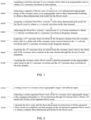
FIG. 1 is a flow chart of a method for acquiring coronary artery blood vessel evaluation parameters based on an angiographic image of the disclosure; -
FIG. 2 is a flowchart of S200 of the disclosure; -
FIG. 3 is a flowchart of S300 of the disclosure; -
FIG. 4 is a flowchart of S500 of the disclosure; -
FIG. 5 is a pressure waveform diagram of a first diastolic phase pressure ratio cadPR of the disclosure; -
FIG. 6 is a pressure waveform diagram of a ratio of diastolic phase less than the average pressure caDFR of the disclosure; -
FIG. 7 is a pressure waveform diagram of an instantaneous wave-free ratio caiFR of the disclosure; -
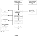
FIG. 8 is a structural block diagram of an embodiment of the device for acquiring coronary artery blood vessel evaluation parameters based on the angiographic image of the disclosure; -
FIG. 9 is a structural block diagram of another embodiment of the device for acquiring coronary artery blood vessel evaluation parameters based on the angiographic image of the disclosure; -
FIG. 10 is a schematic structural diagram of the blood pressure acquisition device of the disclosure; - The reference signs are described below:
bloodpressure acquisition device 100,main body 110, firstpower drive device 120, bloodpressure acquisition unit 130,first control device 140,fixed block 150,second control device 160,infusion device 170,infusion tube 171, three-dimensional modeling unit 200, bloodflow velocity unit 300,pressure drop unit 400, coronary artery blood vesselevaluation parameter unit 500, Fouriertransform module 410, pressuredrop calculation module 420, Fourier transform inverse module 430, caiFRmodule 510,cadPR module 520,caDFR module 530, andcaFFR module 540. - In order to make the objectives, technical solutions and advantages of the present invention clearer, the technical solutions of the present invention will be described clearly and completely in conjunction with specific embodiments of the present invention and the corresponding drawings. Obviously, the described embodiments are only a part of the embodiments of the present invention, rather than all the embodiments. Based on the embodiments of the present invention, all other embodiments obtained by those of ordinary skill in the art without creative work shall fall within the protection scope of the present invention.
- Hereinafter, a number of embodiments of the present invention will be disclosed in drawings. For clear description, many practical details will be described in the following description. However, it should be understood that these practical details should not be configured to limit the present invention. In other words, in some embodiments of the present invention, these practical details are unnecessary. In addition, in order to simplify the drawings, some conventionally used structures and components will be shown in simple schematic ways in the drawings.
- The existing methods for measuring the evaluation parameters of coronary artery blood vessel are mainly: (1) measurement by pressure guide wire, which is expensive, difficult and risky; (2) measurement through two-dimensional coronary artery angiographic images by obtaining a real-time aortic pressure Pa and the measured full-cycle blood flow velocity v, resulting in obtaining only full-cycle coronary artery blood vessel evaluation parameters instead of blood vessel evaluation parameters in a diastolic phase in an angiographic state; and there is no screening of the aortic pressure Pa and the blood flow velocity v, resulting in inaccurate blood vessel evaluation parameters.
- In order to solve the above problems, a method, device, system and storage medium for acquiring the blood flow of the cardiac superficial aorta.
- As shown in
Figure 1 , the present disclosure provides a method for acquiring coronary artery blood vessel evaluation parameters based on an angiographic image, comprising: - S100, acquiring a real-time pressure Pa at a coronary artery inlet in an angiographic state to obtain a Pa-t pressure waveform in time domain;
- S200, subjecting a segment of blood vessel of interest in a two-dimensional angiographic image of the coronary artery in an angiographic state to three-dimensional modeling to obtain a three-dimensional grid model for the blood vessel;
- S300, acquiring a real-time blood flow velocity v of the three-dimensional grid model for the blood vessel to obtain a v-t velocity waveform in the time domain;
- S400, subjecting the blood flow velocity v and pressure Pa to Fourier transform to obtain v'-t velocity waveform and Pa'-t pressure waveform in frequency domain;
- S500, acquiring a ΔP'-t pressure drop waveform in the frequency domain from the coronary artery inlet to a distal end of the coronary artery stenosis based on the v'-t velocity waveform and Pa'-t pressure waveform in the frequency domain;
- S600, acquiring the ΔP-t pressure drop waveform from the coronary artery inlet to the distal end of the coronary artery stenosis in the time domain through the inverse Fourier transform;
- S700, acquiring the coronary artery blood vessel evaluation parameters in the angiographic state based on the Pa-t pressure waveform and the ΔP-t pressure drop waveform in the time domain.
- the disclosure provides a method for acquiring coronary artery blood vessel evaluation parameters based on an angiographic image, by acquiring Pa-t pressure waveform in an angiographic state in the time domain, and then subjecting the coronary artery two-dimensional angiographic image in the angiographic state to three-dimensional modeling to obtain v-t velocity waveform in the time domain, thereby realizing the measurement of the coronary artery vessel evaluation parameters in a diastolic phase; further, filtering interference data through the Fourier transform improves the accuracy of the coronary artery vessel evaluation parameter measurement.
-
- S100: acquiring a real-time pressure Pa at a coronary artery inlet in an angiographic state to obtain a Pa-t pressure waveform in time domain, comprising:
real-time measuring of the pressure Pa at the coronary artery inlet through a blood pressure acquisition device connected with a catheter for angiography, and drawing a curve with time to obtain the Pa-t pressure waveform in the time domain; - S200: subjecting a segment of blood vessel of interest in a two-dimensional angiographic image of the coronary artery in an angiographic state to three-dimensional modeling to obtain a three-dimensional grid model for the blood vessel, as shown in
Figure 2 , comprising: - S210, reading at least two coronary artery angiographic images with different angles; further comprising: denoising the coronary artery angiographic images; the position shooting angle of the two coronary artery angiographic images being greater than or equal to 30°;
comprising: static noise and dynamic noise; static noise is noise that is static in time, such as ribs in the chest cavity; dynamic noise is noise that changes in time, such as part of lung tissue and part of heart tissue; and comprising: through gray-level histogram analysis, using threshold to further denoise. - S220, subjecting a certain segmented blood vessel on the two coronary artery angiographic images with a mapping relationship to a 3D reconstruction through 2D structure data to obtain a 3D model and 3D data of the segmented blood vessel;
- S230: repeating the above steps until the three-dimensional reconstructions of all the segmented blood vessels are completed, and then merging all the reconstructed segmented blood vessels to obtain a complete three-dimensional grid model for the blood vessel;
- S300: acquiring a real-time blood flow velocity v of the three-dimensional grid model for the blood vessel to obtain a v-t velocity waveform in the time domain, as shown in
Fig. 3 , comprising: - S310: acquiring a start point of the diastolic phase from an image corresponding to a two-dimensional starting frame and an end point of the diastolic phase from an image corresponding to a two-dimensional end frame, respectively; and taking a length L of the blood vessel during the diastolic phase from three-dimensional grid model for the blood vessel by using the start point and the end point, comprising: removing interfering blood vessels, extracting the coronary centerline and diameter of the blood vessel of interest along the extension direction of the coronary artery;
- S320, acquiring a length difference for a flow of a contrast agent in the blood vessel between two adjacent frames of images according to a patient's heart rate and the number of frames used for the coronary artery angiographic images in a certain diastolic phase, and acquiring the contrast agent speed of each frame of the coronary artery angiographic image, namely the real-time blood flow velocity v of the three-dimensional grid model for the blood vessel, the specific formula being as follows:
- (1) If the real-time blood flow velocity v is the blood flow velocity in the diastolic phase, then


wherein, ΔL represents the length difference for the flow of the contrast agent in the blood vessel between two adjacent frames of images, H represents the patient's heart rate with a unit of beats/min; y represents the number of frames of the coronary artery angiographic images in the diastolic phase, wherein t represents the time for the diastolic phase in the Pa-t pressure waveform, T represents the time for the whole cardiac cycle in the Pa-t pressure waveform; - (2) If the real-time blood flow velocity v is the blood flow velocity of the whole cardiac cycle, then

wherein, ΔL represents the length difference for the flow of the contrast agent in the blood vessel between two adjacent frames of images, H represents the patient's heart rate with a unit of beats/min, and x represents the number of the frames of the coronary artery angiographic images within the cardiac cycle;
- (1) If the real-time blood flow velocity v is the blood flow velocity in the diastolic phase, then
- S330: plotting the blood flow velocity v against time to obtain the v-t velocity waveform in the time domain;
- S400: subjecting Fourier transform to the blood flow velocity v and pressure Pa to obtain v'-t velocity waveform and Pa'-t pressure waveform in frequency domain;
- S500, acquiring a ΔP'-t pressure drop waveform in the frequency domain from the coronary artery inlet to the distal end of the coronary artery stenosis based on the v'-t velocity waveform and Pa'-t pressure waveform in the frequency domain, as shown in
Figure 4 , comprising: - S510, using numerical methods to solve the continuity and using Navier-Stokes equation to calculate the pressure drop ΔP' from the inlet to various points in the downstream along the center line of blood vessels, an inlet boundary condition being the blood flow velocity v' in the frequency domain, and an outlet boundary condition being the out-flow boundary condition;
- wherein, the continuity and Navier-Stokes equation are:


-
V, P, ρ, µ represent a coronary artery blood flow velocity, a pressure, a blood flow density, and a blood flow viscosity, respectively; - S520, plotting the pressure drop ΔP' against time to obtain the ΔP'-t pressure drop waveform in the frequency domain;
- S600: acquiring the ΔP-t pressure drop waveform from the coronary artery inlet to the distal end of the coronary artery stenosis in the time domain through the inverse Fourier transform;
- S700, acquiring the coronary artery blood vessel evaluation parameters in the angiographic state based on the Pa-t pressure waveform and the ΔP-t pressure drop waveform in the time domain, comprising: instantaneous wave-free ratio caiFR in the angiographic state, a first diastolic phase pressure ratio in the angiographic state cadPR, a ratio of diastolic phase less than the average pressure in the angiographic state caDFR, and fractional flow reserve caFFR, then:
- (1) as shown in
Figure 5 , the first diastolic phase pressure ratio cadPR is obtained through the first mean pressure of aortaP a1 in the full diastolic phase (namely Diastole strip area inFigure 5 ) and the first mean pressure of a distal end of artery stenosisP d1 , namely: cadPR=P d1 /P a1 ; - (2) as shown in
Figure 6 , the ratio of diastolic phase less than the average pressure caDFR is obtained through the second mean pressure of aortaP a2 and the second mean pressure of a distal end of coronary artery stenosisP d2 within an interval from Pm <P a1 to the aortic pressure Pn =Pmin, wherein Pm and Pn indicate mth and nth aortic pressures during the diastolic phase, respectively, namely: caDFR=P d2 /P a2 , Pmin indicates the minimum aortic pressure; - (3) as shown in
Figure 7 , the instantaneous wave-free ratio caiFR is obtained through the third mean pressure of aortaP a3 and the third mean pressure of a distal end of coronary artery stenosis within the period of wave-free, namely: caiFR=P d3 /P a3 ;
- (1) as shown in
- The wave-free is defined as a certain period of time in the diastolic phase, which is called the wave-free period.
- The calculation time for the instantaneous wave-free period is calculated from 25% of the time after the start of the wave-free period to 5ms before the start of a systolic phase.
- (4) The fractional flow reserve caFFR is obtained through the fourth mean pressure of aorta
P a4 and the fourth mean pressure of a distal end of coronary artery stenosisP d4 in the whole cardiac cycle, namely:
- In another embodiment of the present disclosure, the blood flow velocity v in S300 is calculated by v = ΔL/fps , where ΔL represents the length difference between the blood vessels in which the contrast agents of two adjacent frames of image are flowing, and fps represents the number of frames transmitted per second.
- As shown in
FIG. 8 , the present disclosure provides an device for acquiring coronary artery blood vessel evaluation parameters based on an angiographic image and the device is used in the method for acquiring coronary artery blood vessel evaluation parameters based on the angiographic image, and the device comprises: a blood pressure acquisition device 100, and a three-dimensional modeling unit 200, a blood flow velocity unit 300, a pressure drop unit 400, and a coronary artery blood vessel evaluation parameter unit 500 connected in sequence, and the blood pressure acquisition device 100 is connected to the pressure drop unit 400; the blood pressure acquisition device 100 is connected to an external catheter for angiography and for acquiring a real-time pressure Pa at a coronary artery inlet in an angiographic state to obtain a Pa-t pressure waveform in time domain; the three-dimensional modeling unit 200 is configured for reading the coronary artery angiographic image in the angiographic state, and subjecting a segment of blood vessel of interest in the image to three-dimensional modeling to obtain a three-dimensional grid model for the blood vessel; the blood flow velocity unit 300 is configured for receiving the three-dimensional grid model for the blood vessel sent by the three-dimensional modeling unit 200 and acquiring a real-time blood flow velocity v of the segment of blood vessel of interest to obtain v-t velocity waveform in the time domain; as shown inFIG. 6 , the pressure drop unit 400 also comprises: a Fourier transform module 410, a pressure drop calculation module 420, and a Fourier transform inverse module 430 sequentially connected, and a Fourier transform module 410 is configured to receive the v-t velocity waveform and the Pa-t pressure waveform in the time domain sent by the blood flow velocity unit 300 and the blood pressure acquisition device 100, respectively, and the blood flow velocity v and pressure Pa is subjected to Fourier transform to obtain v'-t velocity waveform and Pa'-t pressure waveform in frequency domain; the pressure drop calculation module 420 is then configured to acquire a ΔP'-t pressure drop waveform in the frequency domain from the coronary artery inlet to the distal end of the coronary artery stenosis based on the v'-t velocity waveform and Pa'-t pressure waveform in the frequency domain sent by the Fourier transform module 410; the Fourier transform inverse module 430 is configured to acquire the ΔP-t pressure drop waveform from the coronary artery inlet to the distal end of the coronary artery stenosis in the time domain through the inverse Fourier transform according to the ΔP'-t pressure drop waveform sent by the pressure drop calculation module 420; the coronary artery blood vessel evaluation parameter unit 500 is configured for receiving the Pa-t pressure waveform and the ΔP-t pressure drop waveform in the time domain sent by the blood pressure acquisition device 100 and the pressure drop unit 400 to acquire the coronary artery blood vessel evaluation parameters. - In an embodiment of the present disclosure, as shown in
FIG. 9 , the coronary artery blood vesselevaluation parameter unit 500 further comprises: acaiFR module 510, acadPR module 520, acaDFR module 530, and acaFFR module 540, which are all connected to the Fourier transform inverse module 430. The cadPR module 520 is configured to select the waveform in the full diastolic phase from the Pa-t pressure waveform and the ΔP-t pressure drop waveform in the time domain sent by the pressure drop unit 400, and obtain the first diastolic phase pressure ratio cadPR through the first mean pressure of aortaP a1 in the full diastolic phase and the first mean pressure of a distal end of artery stenosis P d1; the caDFR module 530 is configured to select an interval waveform from Pm <P a1 to the aortic pressure Pn =Pmin from the Pa-t pressure waveform and the ΔP-t pressure drop waveform in the time domain sent by the pressure drop unit 400, and obtain the ratio of a diastolic phase less than the average pressure caDFR through the second mean pressure of aortaP a2 and the second mean pressure of a distal end of coronary artery stenosisP d2 , wherein Pm and Pn indicate mth and nth aortic pressures during the diastolic phase, respectively; the caiFR module 510 is configured to select the waveform in the wave-free period from the Pa-t pressure waveform and the ΔP-t pressure drop waveform in the time domain sent by the pressure drop unit 400, and obtain the instantaneous wave-free ratio caiFR through the third mean pressure of aortaP Q3 and the third mean pressure of a distal end of coronary artery stenosisP d3 within the period of wave-free; the fractional flow reserve caFFR is configured to select all data from the Pa-t pressure waveform and the ΔP-t pressure drop waveform in the time domain sent by the pressure drop unit 400 as the whole cardiac cycle data, and obtain fractional flow reserve caFFR through the fourth mean pressure of aortaP a4 and the fourth mean pressure of a distal end of coronary artery stenosisP d4 in the whole cardiac cycle. - In an embodiment of the present disclosure, as shown in
FIG. 10 , the blood pressure acquisition device 100 comprises: a main body 110, and a first power drive device 120, a blood pressure acquisition unit 130, and a first control device 140 that are all connected to the main body 110; the main body 110 is configured to control whether the first power drive device 120, the blood pressure acquisition unit 130, and the first control device 140 start working; the blood pressure acquisition unit 130 is connected to the second control device 160, and the second control device 160 is connected to an external interventional device; the second control device 160 is configured for zeroing the blood pressure acquisition unit 130 and for controlling whether the blood pressure acquisition unit 130 is in communication with the external interventional device; the first power drive device 120 is arranged on the main body 110, and the first power drive device 120 is connected to the external infusion device 170, and the first power drive device 120 is configured to drive the liquid flow of the external infusion device 170; the blood pressure acquisition unit 130 is arranged on the main body 110, and the blood pressure acquisition unit 130 is connected to the first control device 140 and the external interventional device, and the blood pressure acquisition unit 130 is configured to collect the invasive arterial pressure; the first control device 140 is fixed on the main body 110 through the fixing block 150, etc.; the first control device 140 is connected to the external infusion device 170 for controlling the liquid flow direction of the infusion device 170, which causes the liquid to flow from the infusion device 170 to the first control device 140. The present disclosure provides a blood pressure acquisition device, and by setting the firstpower drive device 120, the bloodpressure acquisition unit 130, and thefirst control device 140 on themain body 110 and by opening thefirst control device 140, the bloodpressure acquisition unit 130 is in communication with theexternal infusion device 170 and atmosphere at the same time, so that the firstpower drive device 120 drives the liquid flow inside the infusion tube 7100 on theexternal infusion device 170, thereby realizing automatic discharge without manual discharge, which is simple and convenient to operate; the automatic zero calibration of the bloodpressure acquisition unit 130 can be realized by setting thesecond control device 160; because the height change of the operating bed will affect the measurement of the invasive arterial pressure, the height of the blood pressure acquisition device needs to be changed during an operation, and there is no need to repeat the zero calibration many times, and the operation is simple and the measurement is accurate. - In a third aspect, the present disclosure provides a coronary artery analysis system, comprising: the above device for acquiring coronary artery blood vessel evaluation parameters based on an angiographic image.
- In a fourth aspect, the present disclosure provides a computer storage medium, and when the computer program is executed by a processor, the above method for acquiring coronary artery blood vessel evaluation parameters based on an angiographic image is realized.
- Those skilled in the art know that various aspects of the present invention can be implemented as a system, a method, or a computer program product. Therefore, each aspect of the present invention can be specifically implemented in the following forms, namely: complete hardware implementation, complete software implementation (comprising firmware, resident software, microcode, etc.), or a combination of hardware and software implementations, Here can be collectively referred to as "circuit", "module" or "system". In addition, in some embodiments, various aspects of the present invention may also be implemented in the form of a computer program product in one or more computer-readable media, and the computer-readable medium contains computer-readable program code. Implementation of methods and/or systems of embodiments of the present invention may involve performing or completing selected tasks manually, automatically, or a combination thereof.
- For example, hardware for performing selected tasks according to an embodiment of the present invention may be implemented as a chip or a circuit. As software, selected tasks according to an embodiment of the present invention can be implemented as a plurality of software instructions executed by a computer using any suitable operating system. In an exemplary embodiment of the present invention, a data processor performs one or more tasks according to an exemplary embodiment of a method and/or system as herein, such as a computing platform for executing a plurality of instructions. Optionally, the data processor includes a volatile memory for storing instructions and/or data and/or a non-volatile memory for storing instructions and/or data, for example, a magnetic hard disk and/or a removable medium. Optionally, a network connection is also provided. Optionally, a display and/or user input device, such as a keyboard or mouse, is also provided.
- Any combination of one or more computer readable can be utilized. The computer-readable medium may be a computer-readable signal medium or a computer-readable storage medium. The computer-readable storage medium may be, for example, but not limited to, an electrical, magnetic, optical, electromagnetic, infrared, or semiconductor system, apparatus, or device, or any combination of the above. More specific examples (non-exhaustive list) of computer-readable storage media would include the following:
- Electrical connection with one or more wires, portable computer disk, hard disk, random access memory (RAM), read only memory (ROM), erasable programmable read only memory (EPROM or flash memory), optical fiber, portable compact disk read only memory (CD-ROM), optical storage device, magnetic storage device, or any suitable combination of the above. In this document, the computer-readable storage medium can be any tangible medium that contains or stores a program, and the program can be used by or in combination with an instruction execution system, apparatus, or device.
- The computer-readable signal medium may include a data signal propagated in baseband or as a part of a carrier wave, and computer-readable program code is carried therein. This propagated data signal can take many forms, comprising but not limited to electromagnetic signals, optical signals, or any suitable combination of the above. The computer-readable signal medium may also be any computer-readable medium other than the computer-readable storage medium. The computer-readable medium may send, propagate, or transmit the program use by or in combination with the instruction execution system, apparatus, or device.
- The program code contained on the computer-readable medium can be transmitted by any suitable medium, comprising (but not limited to) wireless, wired, optical cable, RF, etc., or any suitable combination of the foregoing.
- For example, any combination of one or more programming languages can be configured to write computer program codes for performing operations for various aspects of the present invention, comprising object-oriented programming languages such as Java, Smalltalk, C++, and conventional process programming languages, such as "C" programming language or similar programming language. The program code may be executed entirely on the user's computer, partly on the user's computer, executed as an independent software package, partly on the user's computer and partly executed on a remote computer, or entirely executed on the remote computer or server. In the case of a remote computer, the remote computer can be connected to the user's computer through any kind of network comprising a local area network (LAN) or a wide area network (WAN), or it can be connected to an external computer (for example, using an Internet service provider to pass Internet connection).
- It should be understood that each block of the flowchart and/or block diagram and the combination of each block in the flowchart and/or block diagram may be implemented by computer program instructions. These computer program instructions can be provided to the processors of general-purpose computers, special-purpose computers, or other programmable data processing devices, thereby producing a machine that makes these computer program instructions when executed by the processors of the computer or other programmable data processing devices, a device that implements the functions/actions specified in one or more blocks in the flowchart and/or block diagram is produced.
- It is also possible to store these computer program instructions in a computer-readable medium. These instructions make computers, other programmable data processing devices, or other devices work in a specific manner, so that the instructions stored in the computer-readable medium generate an article of manufacture that implements instructions for functions/actions specified in one or more blocks in the flowchart and/or block diagram.
- Computer program instructions can also be loaded onto a computer (for example, a coronary artery analysis system) or other programmable data processing equipment to cause a series of operation steps to be performed on the computer, other programmable data processing equipment or other equipment to produce a computer-implemented process , causing instructions executed on a computer, other programmable device or other equipment to provide a process for implementing the functions/actions specified in the flowchart and/or one or more block diagrams.
- The above specific examples of the present invention further describe the objectives, technical solutions and beneficial effects of the present invention in detail. It should be understood that the above are only specific embodiments of the present invention and are not intended to limit the present invention.
Claims (14)
- A method for acquiring coronary artery blood vessel evaluation parameters based on an angiographic image, characterized in that, comprising the following steps:acquiring (S100) a real-time pressure Pa at a coronary artery inlet in an angiographic state to obtain a Pa-t pressure waveform in time domain;subjecting (S200) a segment of blood vessel of interest in a two-dimensional angiographic image of the coronary artery in an angiographic state to three-dimensional modeling to obtain a three-dimensional grid model for the blood vessel;acquiring (S300) a real-time blood flow velocity v of the three-dimensional grid model for the blood vessel to obtain a v-t velocity waveform in the time domain;subjecting (S400) the blood flow velocity v and pressure Pa to Fourier transform to obtain v'-t velocity waveform and Pa'-t pressure waveform in frequency domain;acquiring (S500) a ΔP'-t pressure drop waveform in the frequency domain from the coronary artery inlet to a distal end of the coronary artery stenosis based on the v'-t velocity waveform and Pa'-t pressure waveform in the frequency domain;acquiring (S600) the ΔP-t pressure drop waveform from the coronary artery inlet to the distal end of the coronary artery stenosis in the time domain through the inverse Fourier transform;acquiring (S700) the coronary artery blood vessel evaluation parameters in the angiographic state based on the Pa-t pressure waveform and the ΔP-t pressure drop waveform in the time domain.
- The method for acquiring the coronary artery blood vessel evaluation parameters based on the angiographic image according to claim 1, wherein the blood vessel evaluation parameters comprise: instantaneous wave-free ratio caiFR in the angiographic state, a first diastolic phase pressure ratio in the angiographic state cadPR and a ratio of diastolic phase less than the average pressure in the angiographic state caDFR; wherein,the first diastolic phase pressure ratio cadPR is obtained through the first mean pressure of aorta
P a1 in the full diastolic phase and the first mean pressure of a distal end of artery stenosisP d1 ;the ratio of diastolic phase less than the average pressure caDFR is obtained through the second mean pressure of aortaP a2 and the second mean pressure of a distal end of coronary artery stenosisP d2 within an interval from Pm <P a1 to the aortic pressure Pn =Pmin, wherein Pm and Pn indicate mth and nth aortic pressures during the diastolic phase, respectively, and Pmin indicates the minimum aortic pressure;the instantaneous wave-free ratio caiFR is obtained through the third mean pressure of aortaP a3 and the third mean pressure of a distal end of coronary artery stenosisP d3 within the period of wave-free. - The method for acquiring the coronary artery blood vessel evaluation parameters based on the angiographic image according to claim 2, wherein calculation formulas of the instantaneous wave-free ratio caiFR, the first diastolic pressure ratio cadPR and the ratio of diastolic phase less than the average pressure caDFR each are:

- The method for acquiring the coronary artery blood vessel evaluation parameters based on an angiographic image according to claim 1, wherein the blood vessel evaluation parameters further comprise: fractional flow reserve caFFR; wherein,
fractional flow reserve caFFR is obtained through the fourth mean pressure of aortaP a4 and the fourth mean pressure of a distal end of coronary artery stenosisP d4 in the whole cardiac cycle, namely: caFFR=Pd4 /Pa4 . - The method for acquiring the coronary artery blood vessel evaluation parameters based on the angiographic image according to claim 1, wherein the step for acquiring the real-time pressure Pa at the coronary artery inlet in the angiographic state to obtain the Pa-t pressure waveform in the time domain comprises: real-time measuring the pressure Pa at the coronary artery inlet through a blood pressure acquisition device connected with a catheter for angiography, and drawing a curve with time to obtain the Pa-t pressure waveform in the time domain.
- The method for acquiring the coronary artery blood vessel evaluation parameters based on the angiographic image according to claim 5, wherein the step for subjecting the segment of the blood vessel of interest in the two-dimensional angiographic image of the coronary artery in the angiographic state to three-dimensional modeling to obtain the three-dimensional grid model for the blood vessel comprises:reading (S210) at least two coronary artery angiographic images with different angles;subjecting (S220) a certain segmented blood vessel on the two coronary angiographic images with a mapping relationship to a 3D reconstruction through 2D structure data to obtain a 3D model and 3D data of the segmented blood vessel;repeating (S230) the above steps until the three-dimensional reconstructions of all the segmented vessels are completed, and then merging all the reconstructed segmented vessels to obtain a complete three-dimensional vessel grid model.
- The method for acquiring coronary artery blood vessel evaluation parameters based on the angiographic image according to claim 6, wherein the step for acquiring the real-time blood flow velocity v of the three-dimensional grid model for the blood vessel to obtain the v-t velocity waveform in the time domain comprises:acquiring (S310) a start point of the diastolic phase from an image corresponding to a two-dimensional starting frame and an end point of the diastolic phase from an image corresponding to a two-dimensional end frame, respectively; and taking a length L of the blood vessel in the diastolic phase from three-dimensional grid model for the blood vessel by using the start point and the end point;acquiring (S320) the length difference between the blood vessels in which the contrast agents of two adjacent frames of images are flowing according to a patient's heart rate and the number of frames the coronary artery angiographic images passing through in a certain diastolic phase, and acquiring the contrast agent speed of each frame of the coronary artery angiographic image, namely the real-time blood flow velocity v in the diastolic phase of the three-dimensional grid model for the blood vessel, the specific formula being as follows:

 wherein, ΔL represents the length difference for the flow of the contrast agent in the blood vessel between two adjacent frames of images, H represents the patient's heart rate with a unit of beats/min; y represents the number of frames of the coronary artery angiographic images in the diastolic phase, wherein t represents the time for the diastolic phase in the Pa-t pressure waveform, T represents the time for the whole cardiac cycle in the Pa-t pressure waveform;plotting (S330) the blood flow velocity v against time to obtain the v-t velocity waveform in the time domain in the diastolic phase.
 - The method for acquiring coronary artery blood vessel evaluation parameters based on an angiographic image according to claim 1, wherein the step for acquiring the real-time blood flow velocity v of the three-dimensional grid model for blood vessel to obtain the v-t velocity waveform in the time domain comprises:acquiring a start point of the cardiac cycle from an image corresponding to a two-dimensional starting frame and an end point of the cardiac cycle from an image corresponding to a two-dimensional end frame, respectively; and taking a length L of the blood vessel within one cardiac cycle from three-dimensional grid model for the blood vessel by using the start point and the end point;acquiring a length difference for a flow of a contrast agent in the blood vessel between two adjacent frames of images according to a patient's heart rate and the number of frames used for the coronary artery angiographic images in a certain cardiac cycle, and acquiring the contrast agent speed of each frame of the coronary artery angiographic image, namely the real-time blood flow velocity v in the whole cardiac cycle of the three-dimensional grid model for the blood vessel, the specific formula being as follows:
 wherein, ΔL represents the length difference for the flow of the contrast agent in the blood vessel between two adjacent frames of images, H represents the patient's heart rate with a unit of beats/min, and x represents the number of the frames of the coronary artery angiographic images within the cardiac cycle;plotting the blood flow velocity v against time to obtain the v-t velocity waveform in the time domain in the cardiac cycle.
 - The method for acquiring coronary artery blood vessel evaluation parameters based on an angiographic image according to claim 1, wherein the step for acquiring a real-time blood flow velocity v of the three-dimensional grid model for blood vessel comprises:

- The method for acquiring coronary artery blood vessel evaluation parameters based on an angiographic image according to claim 1, wherein the step for acquiring the ΔP'-t pressure drop waveform in the frequency domain from the coronary artery inlet to the distal end of the coronary artery stenosis based on the v'-t velocity waveform and Pa'-t pressure waveform in the frequency domain comprises:using (S510) numerical methods to solve the continuity and using Navier-Stokes equation to solve the pressure drop ΔP' from the coronary artery inlet to the distal end of the coronary artery stenosis, the specific formula being as follows:
 wherein, V, P, ρ, µ represent a coronary artery blood flow velocity, a pressure, a blood flow density, and a blood flow viscosity, respectively;an inlet boundary condition being the blood flow velocity v' in the frequency domain, and the outlet boundary condition being the out-flow boundary condition;calculating the pressure drop ΔP' from the inlet to various points in the downstream along the centerline of the blood vessel;plotting (S520) the pressure drop ΔP' against time to obtain the ΔP'-t pressure drop waveform in the frequency domain.
 - A device for acquiring coronary artery blood vessel evaluation parameters based on an angiographic image, which is used in the method for acquiring coronary artery blood vessel evaluation parameters based on an angiographic image according to any one of claims 1-10, characterized in that, comprising: a blood pressure acquisition device (100); and a three-dimensional modeling unit (200), a blood flow velocity unit (300), a pressure drop unit (400), and a coronary artery blood vessel evaluation parameter unit (500) connected in sequence, and the blood pressure acquisition device (100) being connected to the pressure drop unit (400);the blood pressure acquisition device (100) is connected with an external catheter for angiography and configured to acquire a real-time pressure Pa at a coronary artery inlet in an angiographic state to obtain a Pa-t pressure waveform in time domain;the three-dimensional modeling unit (200) is configured to read the coronary artery angiographic image in the angiographic state and subjected a segment of blood vessel of interest in the image to three-dimensional modeling to obtain a three-dimensional grid model for the blood vessel;the blood flow velocity unit (300) is configured to receive the three-dimensional grid model for the blood vessel sent by the three-dimensional modeling unit (200) and acquired a real-time blood flow velocity v of the segment of blood vessel of interest to obtain v-t velocity waveform in the time domain;the pressure drop unit (400) is configured to receive the v-t velocity waveform and the Pa'-t pressure waveform in the time domain sent by the blood flow velocity unit (300) and the blood pressure acquisition device (100), respectively, and subject the blood flow velocity v and pressure Pa to Fourier transform to obtain v'-t velocity waveform and Pa'-t pressure waveform in frequency domain; acquiring a ΔP'-t pressure drop waveform in the frequency domain from the coronary artery inlet to a distal end of the coronary artery stenosis based on the v'-t velocity waveform and Pa'-t pressure waveform in the frequency domain; acquiring the ΔP-t pressure drop waveform from the coronary artery inlet to the distal end of the coronary artery stenosis in the time domain through the inverse Fourier transform;the coronary artery blood vessel evaluation parameter unit (500) is configured to receive the Pa-t pressure waveform and the ΔP-t pressure drop waveform in the time domain sent by the blood pressure acquisition device (100) and the pressure drop unit (400), and acquire the coronary artery blood vessel evaluation parameters.
- The device for acquiring coronary artery blood vessel evaluation parameters based on an angiographic image according to claim 11, wherein the coronary artery vessel evaluation parameter unit (500) further comprises: a caiFR module (510), a cadPR module (520), a caDFR module (530), and a caFFR module (540);the cadPR module (520) is configured to obtain the first diastolic phase pressure ratio cadPR through the first mean pressure of aorta
P a1 in the full diastolic phase and the first mean pressure of a distal end of coronary artery stenosisP d1 ;the caDFR module (530) is configured to obtain the ratio of a diastolic phase less than the average pressure caDFR through the second mean pressure of aortaP a2 and the second mean pressure of a distal end of coronary artery stenosisP d2 within an interval from Pm <P a1 to the aortic pressure Pn =Pmin, wherein Pm and Pn indicate mth and nth aortic pressures during the diastolic phase, respectively, and Pmin indicates the minimum aortic pressure;the caiFR module (510) is configured to obtain the instantaneous wave-free ratio caiFR through the third mean pressure of aortaP a3 and the third mean pressure of a distal end of coronary artery stenosisP d3 within the period of wave-free;the fractional flow reserve caFFR module (540) is configured to obtain fractional flow reserve caFFR through the fourth mean pressure of aortaP a4 and the fourth mean pressure of a distal end of coronary artery stenosisP d4 in the whole cardiac cycle. - A coronary artery analysis system, comprising the device for acquiring coronary artery blood vessel evaluation parameters based on an angiographic image according to claim 11 or 12.
- A computer storage medium, comprising a computer program, which when executed on the device according to claims 11 or 12, performs the method for acquiring coronary artery blood vessel evaluation parameters based on an angiographic image according to any one of claims 1 to 10.
Applications Claiming Priority (4)
| Application Number | Priority Date | Filing Date | Title |
|---|---|---|---|
| CN201811344281.7A CN111166317B (en) | 2018-11-13 | 2018-11-13 | Method for calculating contrast fractional flow reserve and resting state pressure ratio based on contrast image |
| CN201811344060.XA CN111166315B (en) | 2018-11-13 | 2018-11-13 | Method for calculating instantaneous mode-free ratio and resting state diastolic pressure ratio based on contrast image |
| CN201811344074.1A CN111166316B (en) | 2018-11-13 | 2018-11-13 | Method for calculating instantaneous contrast wave-free ratio and contrast diastolic pressure ratio based on contrast images |
| PCT/CN2019/118053 WO2020098704A1 (en) | 2018-11-13 | 2019-11-13 | Method, apparatus and system for acquiring vascular assessment parameter on basis of angiographic image |
Publications (4)
| Publication Number | Publication Date |
|---|---|
| EP3881758A1 EP3881758A1 (en) | 2021-09-22 |
| EP3881758A4 EP3881758A4 (en) | 2022-07-27 |
| EP3881758C0 EP3881758C0 (en) | 2024-09-18 |
| EP3881758B1 true EP3881758B1 (en) | 2024-09-18 |
Family
ID=70730650
Family Applications (1)
| Application Number | Title | Priority Date | Filing Date |
|---|---|---|---|
| EP19885173.5A Active EP3881758B1 (en) | 2018-11-13 | 2019-11-13 | Method, apparatus and system for acquiring vascular assessment parameter on basis of angiographic image |
Country Status (5)
| Country | Link |
|---|---|
| US (1) | US20210236000A1 (en) |
| EP (1) | EP3881758B1 (en) |
| JP (1) | JP7162934B2 (en) |
| CN (2) | CN112384137B (en) |
| WO (2) | WO2020098705A1 (en) |
Cited By (6)
| Publication number | Priority date | Publication date | Assignee | Title |
|---|---|---|---|---|
| US12315076B1 (en) | 2021-09-22 | 2025-05-27 | Cathworks Ltd. | Four-dimensional motion analysis of a patient's coronary arteries and myocardial wall |
| US12354755B2 (en) | 2012-10-24 | 2025-07-08 | Cathworks Ltd | Creating a vascular tree model |
| US12387325B2 (en) | 2022-02-10 | 2025-08-12 | Cath Works Ltd. | System and method for machine-learning based sensor analysis and vascular tree segmentation |
| US12446965B2 (en) | 2023-08-09 | 2025-10-21 | Cathworks Ltd. | Enhanced user interface and crosstalk analysis for vascular index measurement |
| US12499646B1 (en) | 2024-06-12 | 2025-12-16 | Cathworks Ltd. | Three-dimensional sizing tool for cardiac assessment |
| US12531159B2 (en) | 2023-08-09 | 2026-01-20 | Cathworks Ltd. | Post-PCI coronary analysis |
Families Citing this family (18)
| Publication number | Priority date | Publication date | Assignee | Title |
|---|---|---|---|---|
| EP4300419A3 (en) | 2016-05-16 | 2024-04-03 | Cathworks Ltd. | System for vascular assessment |
| CN111227821B (en) * | 2018-11-28 | 2022-02-11 | 苏州润迈德医疗科技有限公司 | Microcirculation resistance index calculation method based on myocardial blood flow and CT (computed tomography) images |
| IL286814B2 (en) | 2019-04-01 | 2026-03-01 | Cathworks Ltd | Methods and apparatus for angiographic image selection |
| EP4555935A3 (en) | 2019-09-23 | 2025-07-30 | Cathworks Ltd. | Methods, apparatus, and system for synchronization between a three-dimensional vascular model and an imaging device |
| US11950893B2 (en) * | 2020-01-17 | 2024-04-09 | The Research Foundation For The State University Of New York | Apparatus and method of determining dynamic vascular parameters of blood flow |
| EP3977934A1 (en) * | 2020-10-02 | 2022-04-06 | Koninklijke Philips N.V. | Systems and methods for performing blood flow velocity measurements |
| US20220392059A1 (en) * | 2021-06-08 | 2022-12-08 | Shenzhen Keya Medical Technology Corporation | Method and system for representation learning with sparse convolution |
| CN113838572B (en) * | 2021-09-10 | 2024-03-01 | 深圳睿心智能医疗科技有限公司 | Vascular physiological parameter acquisition method, vascular physiological parameter acquisition device, electronic equipment and storage medium |
| EP4197429A1 (en) * | 2021-12-14 | 2023-06-21 | Koninklijke Philips N.V. | System and method for determining partial mass of an organ |
| CN116172598A (en) * | 2023-02-22 | 2023-05-30 | 北京医准智能科技有限公司 | Fractional flow reserve determination method, fractional flow reserve determination device, electronic equipment and storage medium |
| CN117036332A (en) * | 2023-08-25 | 2023-11-10 | 上海联影医疗科技股份有限公司 | Blood flow parameter calculation method and system for reticulate blood vessel |
| CN116807514B (en) * | 2023-08-29 | 2024-01-12 | 深圳开立生物医疗科技股份有限公司 | Vascular imaging systems, methods, equipment, electronic devices and storage media |
| CN117576006B (en) * | 2023-11-07 | 2025-04-04 | 北京科莱博特医疗科技有限公司 | Method, device, equipment and medium for determining coronary artery blood flow reserve fraction |
| CN117530718B (en) * | 2023-11-07 | 2025-06-03 | 中日友好医院(中日友好临床医学研究所) | Method, device, computer equipment and medium for determining pulmonary artery blood flow fraction |
| CN119423827B (en) * | 2024-03-04 | 2026-02-13 | 北京大学 | Ultrasonic coronary artery fractional flow reserve measurement method |
| CN118098607B (en) * | 2024-04-29 | 2024-06-28 | 四川大学 | A method, system, device and medium for evaluating coronary artery blood supply function |
| CN118537780B (en) * | 2024-07-25 | 2024-10-01 | 江西核工业兴中新材料有限公司 | A method and system for analyzing acid flow data for producing cobalt acetate |
| CN121714232A (en) * | 2026-02-24 | 2026-03-24 | 深圳市业聚实业有限公司 | Coronary function evaluation device |
Family Cites Families (15)
| Publication number | Priority date | Publication date | Assignee | Title |
|---|---|---|---|---|
| JP4599301B2 (en) * | 2006-01-16 | 2010-12-15 | 三菱重工業株式会社 | Design support apparatus and computer program |
| US8315812B2 (en) * | 2010-08-12 | 2012-11-20 | Heartflow, Inc. | Method and system for patient-specific modeling of blood flow |
| US9119540B2 (en) * | 2010-09-16 | 2015-09-01 | Siemens Aktiengesellschaft | Method and system for non-invasive assessment of coronary artery disease |
| JP5255714B2 (en) * | 2011-05-16 | 2013-08-07 | 住友ゴム工業株式会社 | Three-dimensional fluid simulation method |
| US10162932B2 (en) * | 2011-11-10 | 2018-12-25 | Siemens Healthcare Gmbh | Method and system for multi-scale anatomical and functional modeling of coronary circulation |
| US9135699B2 (en) * | 2012-03-15 | 2015-09-15 | Siemens Aktiengesellschaft | Method and system for hemodynamic assessment of aortic coarctation from medical image data |
| CA2875346A1 (en) * | 2012-06-26 | 2014-01-03 | Sync-Rx, Ltd. | Flow-related image processing in luminal organs |
| CN103995989B (en) * | 2013-02-15 | 2018-11-13 | 西门子公司 | The adjust automatically of the particular patient of boundary condition for tip vascular tree |
| EP3188059B1 (en) * | 2014-08-29 | 2020-05-13 | KNU-Industry Cooperation Foundation | Method for determining patient-specific blood vessel information |
| US10194812B2 (en) * | 2014-12-12 | 2019-02-05 | Medtronic Vascular, Inc. | System and method of integrating a fractional flow reserve device with a conventional hemodynamic monitoring system |
| US10636146B2 (en) * | 2015-05-12 | 2020-04-28 | Singapore Health Services Pte Ltd | Medical image processing methods and systems |
| KR20180110080A (en) * | 2016-02-08 | 2018-10-08 | 스페로 디바이시즈 인코포레이티드 | Analog co-processor |
| JP6653673B2 (en) * | 2017-02-28 | 2020-02-26 | 富士フイルム株式会社 | Blood flow analyzer, method, and program |
| CN108245178A (en) * | 2018-01-11 | 2018-07-06 | 苏州润迈德医疗科技有限公司 | A kind of blood flowing speed computational methods based on X ray coronary angiography image |
| CN108186038B (en) * | 2018-02-11 | 2020-11-17 | 杭州脉流科技有限公司 | System for calculating coronary blood flow reserve fraction based on arteriography image |
-
2019
- 2019-11-13 CN CN201980040566.8A patent/CN112384137B/en active Active
- 2019-11-13 CN CN201980040404.4A patent/CN112384136A/en active Pending
- 2019-11-13 JP JP2021523637A patent/JP7162934B2/en active Active
- 2019-11-13 WO PCT/CN2019/118058 patent/WO2020098705A1/en not_active Ceased
- 2019-11-13 WO PCT/CN2019/118053 patent/WO2020098704A1/en not_active Ceased
- 2019-11-13 EP EP19885173.5A patent/EP3881758B1/en active Active
-
2021
- 2021-04-22 US US17/237,662 patent/US20210236000A1/en not_active Abandoned
Cited By (8)
| Publication number | Priority date | Publication date | Assignee | Title |
|---|---|---|---|---|
| US12354755B2 (en) | 2012-10-24 | 2025-07-08 | Cathworks Ltd | Creating a vascular tree model |
| US12315076B1 (en) | 2021-09-22 | 2025-05-27 | Cathworks Ltd. | Four-dimensional motion analysis of a patient's coronary arteries and myocardial wall |
| US12387325B2 (en) | 2022-02-10 | 2025-08-12 | Cath Works Ltd. | System and method for machine-learning based sensor analysis and vascular tree segmentation |
| US12446965B2 (en) | 2023-08-09 | 2025-10-21 | Cathworks Ltd. | Enhanced user interface and crosstalk analysis for vascular index measurement |
| US12531159B2 (en) | 2023-08-09 | 2026-01-20 | Cathworks Ltd. | Post-PCI coronary analysis |
| US12499646B1 (en) | 2024-06-12 | 2025-12-16 | Cathworks Ltd. | Three-dimensional sizing tool for cardiac assessment |
| US12512196B2 (en) | 2024-06-12 | 2025-12-30 | Cathworks Ltd. | Systems and methods for secure sharing of cardiac assessments using QR codes |
| US12567489B2 (en) | 2024-06-12 | 2026-03-03 | Cathworks Ltd. | Systems and methods for displaying distal fractional flow reserve values in vascular analysis |
Also Published As
| Publication number | Publication date |
|---|---|
| EP3881758C0 (en) | 2024-09-18 |
| CN112384136A (en) | 2021-02-19 |
| CN112384137B (en) | 2023-11-14 |
| WO2020098705A1 (en) | 2020-05-22 |
| WO2020098704A1 (en) | 2020-05-22 |
| US20210236000A1 (en) | 2021-08-05 |
| JP2022506325A (en) | 2022-01-17 |
| EP3881758A4 (en) | 2022-07-27 |
| EP3881758A1 (en) | 2021-09-22 |
| CN112384137A (en) | 2021-02-19 |
| JP7162934B2 (en) | 2022-10-31 |
Similar Documents
| Publication | Publication Date | Title |
|---|---|---|
| EP3881758A1 (en) | Method, apparatus and system for acquiring vascular assessment parameter on basis of angiographic image | |
| JP7196273B2 (en) | Systems and methods for assessing the cardiac system by determining the minimum distal pressure/arterial pressure (PD/PA) ratio | |
| CN111134651B (en) | Method, device and system for calculating fractional flow reserve based on intracavity images and computer storage medium | |
| US10580526B2 (en) | System and method for calculating vessel flow parameters based on angiography | |
| US20220261997A1 (en) | Method and apparatus for acquiring blood vessel evaluation parameter based on physiological parameter, and storage medium | |
| JP6745875B2 (en) | Estimation of flow, resistance or pressure from pressure or flow measurement and angiography | |
| US11779294B2 (en) | Method, device and system for calculating microcirculation indicator based on image and pressure sensor | |
| JP2022554298A (en) | Method and Apparatus for Adjusting Maximum Hyperemic Flow Velocity Based on Microvascular Resistance Index | |
| JP2022544052A (en) | Method and apparatus for correcting blood flow velocity based on contrast-enhanced image interval time | |
| WO2020057324A1 (en) | System for measuring index of microcirculatory resistance and coronary artery analysis system | |
| CN110786842B (en) | Method, device, system and storage medium for measuring diastolic blood flow velocity | |
| CN112384138B (en) | Method, device, system and storage medium for obtaining blood flow of superficial cardiac artery | |
| CN110929604B (en) | Method, device, system and storage medium for screening flow velocity based on contrast image | |
| CN119423827B (en) | Ultrasonic coronary artery fractional flow reserve measurement method |
Legal Events
| Date | Code | Title | Description |
|---|---|---|---|
| STAA | Information on the status of an ep patent application or granted ep patent |
Free format text: STATUS: THE INTERNATIONAL PUBLICATION HAS BEEN MADE |
|
| PUAI | Public reference made under article 153(3) epc to a published international application that has entered the european phase |
Free format text: ORIGINAL CODE: 0009012 |
|
| STAA | Information on the status of an ep patent application or granted ep patent |
Free format text: STATUS: REQUEST FOR EXAMINATION WAS MADE |
|
| 17P | Request for examination filed |
Effective date: 20210423 |
|
| AK | Designated contracting states |
Kind code of ref document: A1 Designated state(s): AL AT BE BG CH CY CZ DE DK EE ES FI FR GB GR HR HU IE IS IT LI LT LU LV MC MK MT NL NO PL PT RO RS SE SI SK SM TR |
|
| DAV | Request for validation of the european patent (deleted) | ||
| DAX | Request for extension of the european patent (deleted) | ||
| A4 | Supplementary search report drawn up and despatched |
Effective date: 20220628 |
|
| RIC1 | Information provided on ipc code assigned before grant |
Ipc: G16H 50/50 20180101ALI20220622BHEP Ipc: G16H 40/63 20180101ALI20220622BHEP Ipc: G16H 50/30 20180101ALI20220622BHEP Ipc: G16H 30/40 20180101ALI20220622BHEP Ipc: G16H 20/17 20180101ALI20220622BHEP Ipc: G06T 7/00 20170101ALI20220622BHEP Ipc: A61B 5/0215 20060101ALI20220622BHEP Ipc: A61B 5/02 20060101ALI20220622BHEP Ipc: A61B 5/00 20060101ALI20220622BHEP Ipc: A61B 6/00 20060101ALI20220622BHEP Ipc: A61B 5/026 20060101AFI20220622BHEP |
|
| REG | Reference to a national code |
Ref country code: DE Ref legal event code: R079 Free format text: PREVIOUS MAIN CLASS: A61B0005026000 Ipc: A61B0006500000 Ref document number: 602019059259 Country of ref document: DE |
|
| GRAP | Despatch of communication of intention to grant a patent |
Free format text: ORIGINAL CODE: EPIDOSNIGR1 |
|
| STAA | Information on the status of an ep patent application or granted ep patent |
Free format text: STATUS: GRANT OF PATENT IS INTENDED |
|
| RIC1 | Information provided on ipc code assigned before grant |
Ipc: G16H 50/30 20180101ALI20240412BHEP Ipc: A61B 6/00 20060101ALI20240412BHEP Ipc: G16H 50/50 20180101ALI20240412BHEP Ipc: G16H 40/63 20180101ALI20240412BHEP Ipc: G16H 30/40 20180101ALI20240412BHEP Ipc: A61B 5/0215 20060101ALI20240412BHEP Ipc: A61B 5/026 20060101ALI20240412BHEP Ipc: G16H 20/17 20180101ALI20240412BHEP Ipc: G06T 7/00 20170101ALI20240412BHEP Ipc: A61B 5/02 20060101ALI20240412BHEP Ipc: A61B 5/00 20060101ALI20240412BHEP Ipc: A61B 6/50 20240101AFI20240412BHEP |
|
| INTG | Intention to grant announced |
Effective date: 20240430 |
|
| GRAS | Grant fee paid |
Free format text: ORIGINAL CODE: EPIDOSNIGR3 |
|
| GRAA | (expected) grant |
Free format text: ORIGINAL CODE: 0009210 |
|
| STAA | Information on the status of an ep patent application or granted ep patent |
Free format text: STATUS: THE PATENT HAS BEEN GRANTED |
|
| AK | Designated contracting states |
Kind code of ref document: B1 Designated state(s): AL AT BE BG CH CY CZ DE DK EE ES FI FR GB GR HR HU IE IS IT LI LT LU LV MC MK MT NL NO PL PT RO RS SE SI SK SM TR |
|
| REG | Reference to a national code |
Ref country code: GB Ref legal event code: FG4D |
|
| REG | Reference to a national code |
Ref country code: CH Ref legal event code: EP |
|
| REG | Reference to a national code |
Ref country code: DE Ref legal event code: R096 Ref document number: 602019059259 Country of ref document: DE |
|
| REG | Reference to a national code |
Ref country code: IE Ref legal event code: FG4D |
|
| U01 | Request for unitary effect filed |
Effective date: 20240919 |
|
| U07 | Unitary effect registered |
Designated state(s): AT BE BG DE DK EE FI FR IT LT LU LV MT NL PT RO SE SI Effective date: 20241011 |
|
| U20 | Renewal fee for the european patent with unitary effect paid |
Year of fee payment: 6 Effective date: 20241122 |
|
| PG25 | Lapsed in a contracting state [announced via postgrant information from national office to epo] |
Ref country code: NO Free format text: LAPSE BECAUSE OF FAILURE TO SUBMIT A TRANSLATION OF THE DESCRIPTION OR TO PAY THE FEE WITHIN THE PRESCRIBED TIME-LIMIT Effective date: 20241218 |
|
| PG25 | Lapsed in a contracting state [announced via postgrant information from national office to epo] |
Ref country code: GR Free format text: LAPSE BECAUSE OF FAILURE TO SUBMIT A TRANSLATION OF THE DESCRIPTION OR TO PAY THE FEE WITHIN THE PRESCRIBED TIME-LIMIT Effective date: 20241219 |
|
| PG25 | Lapsed in a contracting state [announced via postgrant information from national office to epo] |
Ref country code: HR Free format text: LAPSE BECAUSE OF FAILURE TO SUBMIT A TRANSLATION OF THE DESCRIPTION OR TO PAY THE FEE WITHIN THE PRESCRIBED TIME-LIMIT Effective date: 20240918 |
|
| PG25 | Lapsed in a contracting state [announced via postgrant information from national office to epo] |
Ref country code: RS Free format text: LAPSE BECAUSE OF FAILURE TO SUBMIT A TRANSLATION OF THE DESCRIPTION OR TO PAY THE FEE WITHIN THE PRESCRIBED TIME-LIMIT Effective date: 20241218 |
|
| PG25 | Lapsed in a contracting state [announced via postgrant information from national office to epo] |
Ref country code: RS Free format text: LAPSE BECAUSE OF FAILURE TO SUBMIT A TRANSLATION OF THE DESCRIPTION OR TO PAY THE FEE WITHIN THE PRESCRIBED TIME-LIMIT Effective date: 20241218 Ref country code: NO Free format text: LAPSE BECAUSE OF FAILURE TO SUBMIT A TRANSLATION OF THE DESCRIPTION OR TO PAY THE FEE WITHIN THE PRESCRIBED TIME-LIMIT Effective date: 20241218 Ref country code: HR Free format text: LAPSE BECAUSE OF FAILURE TO SUBMIT A TRANSLATION OF THE DESCRIPTION OR TO PAY THE FEE WITHIN THE PRESCRIBED TIME-LIMIT Effective date: 20240918 Ref country code: GR Free format text: LAPSE BECAUSE OF FAILURE TO SUBMIT A TRANSLATION OF THE DESCRIPTION OR TO PAY THE FEE WITHIN THE PRESCRIBED TIME-LIMIT Effective date: 20241219 |
|
| PG25 | Lapsed in a contracting state [announced via postgrant information from national office to epo] |
Ref country code: IS Free format text: LAPSE BECAUSE OF FAILURE TO SUBMIT A TRANSLATION OF THE DESCRIPTION OR TO PAY THE FEE WITHIN THE PRESCRIBED TIME-LIMIT Effective date: 20250118 |
|
| PG25 | Lapsed in a contracting state [announced via postgrant information from national office to epo] |
Ref country code: SM Free format text: LAPSE BECAUSE OF FAILURE TO SUBMIT A TRANSLATION OF THE DESCRIPTION OR TO PAY THE FEE WITHIN THE PRESCRIBED TIME-LIMIT Effective date: 20240918 |
|
| PG25 | Lapsed in a contracting state [announced via postgrant information from national office to epo] |
Ref country code: ES Free format text: LAPSE BECAUSE OF FAILURE TO SUBMIT A TRANSLATION OF THE DESCRIPTION OR TO PAY THE FEE WITHIN THE PRESCRIBED TIME-LIMIT Effective date: 20240918 |
|
| PG25 | Lapsed in a contracting state [announced via postgrant information from national office to epo] |
Ref country code: CZ Free format text: LAPSE BECAUSE OF FAILURE TO SUBMIT A TRANSLATION OF THE DESCRIPTION OR TO PAY THE FEE WITHIN THE PRESCRIBED TIME-LIMIT Effective date: 20240918 Ref country code: PL Free format text: LAPSE BECAUSE OF FAILURE TO SUBMIT A TRANSLATION OF THE DESCRIPTION OR TO PAY THE FEE WITHIN THE PRESCRIBED TIME-LIMIT Effective date: 20240918 |
|
| PG25 | Lapsed in a contracting state [announced via postgrant information from national office to epo] |
Ref country code: SK Free format text: LAPSE BECAUSE OF FAILURE TO SUBMIT A TRANSLATION OF THE DESCRIPTION OR TO PAY THE FEE WITHIN THE PRESCRIBED TIME-LIMIT Effective date: 20240918 |
|
| REG | Reference to a national code |
Ref country code: CH Ref legal event code: PL |
|
| PG25 | Lapsed in a contracting state [announced via postgrant information from national office to epo] |
Ref country code: MC Free format text: LAPSE BECAUSE OF FAILURE TO SUBMIT A TRANSLATION OF THE DESCRIPTION OR TO PAY THE FEE WITHIN THE PRESCRIBED TIME-LIMIT Effective date: 20240918 |
|
| REG | Reference to a national code |
Ref country code: CH Ref legal event code: PL |
|
| PG25 | Lapsed in a contracting state [announced via postgrant information from national office to epo] |
Ref country code: CH Free format text: LAPSE BECAUSE OF NON-PAYMENT OF DUE FEES Effective date: 20241130 |
|
| PLBE | No opposition filed within time limit |
Free format text: ORIGINAL CODE: 0009261 |
|
| STAA | Information on the status of an ep patent application or granted ep patent |
Free format text: STATUS: NO OPPOSITION FILED WITHIN TIME LIMIT |
|
| 26N | No opposition filed |
Effective date: 20250619 |
|
| GBPC | Gb: european patent ceased through non-payment of renewal fee |
Effective date: 20241218 |
|
| PG25 | Lapsed in a contracting state [announced via postgrant information from national office to epo] |
Ref country code: GB Free format text: LAPSE BECAUSE OF NON-PAYMENT OF DUE FEES Effective date: 20241218 |
|
| PG25 | Lapsed in a contracting state [announced via postgrant information from national office to epo] |
Ref country code: IE Free format text: LAPSE BECAUSE OF NON-PAYMENT OF DUE FEES Effective date: 20241113 |
|
| U20 | Renewal fee for the european patent with unitary effect paid |
Year of fee payment: 7 Effective date: 20251127 |
|
| PG25 | Lapsed in a contracting state [announced via postgrant information from national office to epo] |
Ref country code: HU Free format text: LAPSE BECAUSE OF FAILURE TO SUBMIT A TRANSLATION OF THE DESCRIPTION OR TO PAY THE FEE WITHIN THE PRESCRIBED TIME-LIMIT; INVALID AB INITIO Effective date: 20191113 |
|
| PG25 | Lapsed in a contracting state [announced via postgrant information from national office to epo] |
Ref country code: CY Free format text: LAPSE BECAUSE OF FAILURE TO SUBMIT A TRANSLATION OF THE DESCRIPTION OR TO PAY THE FEE WITHIN THE PRESCRIBED TIME-LIMIT; INVALID AB INITIO Effective date: 20191113 |